EP3433596B1 - Probenahmevorrichtung zur entnahme einer probe eines gasstroms mit teilchenförmigem material und verfahren zur verwendung davon - Google Patents
Probenahmevorrichtung zur entnahme einer probe eines gasstroms mit teilchenförmigem material und verfahren zur verwendung davon Download PDFInfo
- Publication number
- EP3433596B1 EP3433596B1 EP17726424.9A EP17726424A EP3433596B1 EP 3433596 B1 EP3433596 B1 EP 3433596B1 EP 17726424 A EP17726424 A EP 17726424A EP 3433596 B1 EP3433596 B1 EP 3433596B1
- Authority
- EP
- European Patent Office
- Prior art keywords
- gas stream
- sample
- particulate matter
- concentration
- duct
- Prior art date
- Legal status (The legal status is an assumption and is not a legal conclusion. Google has not performed a legal analysis and makes no representation as to the accuracy of the status listed.)
- Active
Links
Images


Classifications
-
- G—PHYSICS
- G01—MEASURING; TESTING
- G01N—INVESTIGATING OR ANALYSING MATERIALS BY DETERMINING THEIR CHEMICAL OR PHYSICAL PROPERTIES
- G01N1/00—Sampling; Preparing specimens for investigation
- G01N1/02—Devices for withdrawing samples
- G01N1/22—Devices for withdrawing samples in the gaseous state
- G01N1/2247—Sampling from a flowing stream of gas
-
- B—PERFORMING OPERATIONS; TRANSPORTING
- B07—SEPARATING SOLIDS FROM SOLIDS; SORTING
- B07B—SEPARATING SOLIDS FROM SOLIDS BY SIEVING, SCREENING, SIFTING OR BY USING GAS CURRENTS; SEPARATING BY OTHER DRY METHODS APPLICABLE TO BULK MATERIAL, e.g. LOOSE ARTICLES FIT TO BE HANDLED LIKE BULK MATERIAL
- B07B7/00—Selective separation of solid materials carried by, or dispersed in, gas currents
- B07B7/01—Selective separation of solid materials carried by, or dispersed in, gas currents using gravity
-
- G—PHYSICS
- G01—MEASURING; TESTING
- G01N—INVESTIGATING OR ANALYSING MATERIALS BY DETERMINING THEIR CHEMICAL OR PHYSICAL PROPERTIES
- G01N1/00—Sampling; Preparing specimens for investigation
- G01N1/02—Devices for withdrawing samples
- G01N1/22—Devices for withdrawing samples in the gaseous state
- G01N1/2247—Sampling from a flowing stream of gas
- G01N1/2258—Sampling from a flowing stream of gas in a stack or chimney
-
- G—PHYSICS
- G01—MEASURING; TESTING
- G01N—INVESTIGATING OR ANALYSING MATERIALS BY DETERMINING THEIR CHEMICAL OR PHYSICAL PROPERTIES
- G01N1/00—Sampling; Preparing specimens for investigation
- G01N1/28—Preparing specimens for investigation including physical details of (bio-)chemical methods covered elsewhere, e.g. G01N33/50, C12Q
- G01N1/44—Sample treatment involving radiation, e.g. heat
-
- G—PHYSICS
- G01—MEASURING; TESTING
- G01N—INVESTIGATING OR ANALYSING MATERIALS BY DETERMINING THEIR CHEMICAL OR PHYSICAL PROPERTIES
- G01N15/00—Investigating characteristics of particles; Investigating permeability, pore-volume or surface-area of porous materials
- G01N15/10—Investigating individual particles
- G01N15/14—Optical investigation techniques, e.g. flow cytometry
- G01N15/1404—Handling flow, e.g. hydrodynamic focusing
-
- G—PHYSICS
- G01—MEASURING; TESTING
- G01N—INVESTIGATING OR ANALYSING MATERIALS BY DETERMINING THEIR CHEMICAL OR PHYSICAL PROPERTIES
- G01N1/00—Sampling; Preparing specimens for investigation
- G01N1/02—Devices for withdrawing samples
- G01N1/22—Devices for withdrawing samples in the gaseous state
- G01N1/2202—Devices for withdrawing samples in the gaseous state involving separation of sample components during sampling
- G01N2001/222—Other features
- G01N2001/2223—Other features aerosol sampling devices
-
- G—PHYSICS
- G01—MEASURING; TESTING
- G01N—INVESTIGATING OR ANALYSING MATERIALS BY DETERMINING THEIR CHEMICAL OR PHYSICAL PROPERTIES
- G01N1/00—Sampling; Preparing specimens for investigation
- G01N1/02—Devices for withdrawing samples
- G01N1/22—Devices for withdrawing samples in the gaseous state
- G01N1/2247—Sampling from a flowing stream of gas
- G01N2001/2264—Sampling from a flowing stream of gas with dilution
-
- G—PHYSICS
- G01—MEASURING; TESTING
- G01N—INVESTIGATING OR ANALYSING MATERIALS BY DETERMINING THEIR CHEMICAL OR PHYSICAL PROPERTIES
- G01N1/00—Sampling; Preparing specimens for investigation
- G01N1/02—Devices for withdrawing samples
- G01N1/22—Devices for withdrawing samples in the gaseous state
- G01N2001/2285—Details of probe structures
Definitions
- the present disclosure relates generally to particulate discharge and, more particularly, to methods, systems, and apparatus that can be used to monitor particulate discharge for both manual and continuous applications.
- FIG. 1 is a diagram that illustrates a conventional sampling probe used to divert a sample of a gas stream containing particulate matter (PM) for evaluating the concentration of the particulate matter in the gas stream.
- PM particulate matter
- a probe 115 is configured to extend into the gas stream and divert a sample of the gas stream to a particulate matter analysis component 125 to evaluate the concentration of the PM in the stream.
- an angle ⁇ formed by a ray corresponding to the direction of the gas flow through the probe 115 and a ray corresponding to the direction of the earth's gravitational force is greater than 90 degrees.
- PM that is deposited in the probe 115 may not be detected by the particulate matter analysis component 125, which may bias the results of the PM concentration determination.
- Conventional particulate monitoring systems, devices, or instruments may use cyclonic heating to remove moisture from PM before evaluating the concentration of the particulate matter with a detector.
- Processing the sampled gas flow with a cyclonic heater may result in further loss of PM as it is common for a portion of the PM to become trapped in the cyclonic heater. While configuring the probe 115 as shown in FIG. 1 to take advantage of the effects of gravity pulling water droplets back towards the main gas flow in the stack or duct 105 may allow the probe 115 to self-clean, particulate matter from a sample may nonetheless be lost affecting the accuracy of a PM concentration determination.
- US 2,461,584 describes an air separation method for slurry separation.
- US 5,975,309 describes a fluidized-bed classifier.
- JP H09 15118 A describes a sampler employed in a chip drier or the like.
- JP H09 318501 A describes sampling equipment for powder.
- DD 277 378 A3 describes a method and an apparatus for the expansion of steam-gas mixtures for analysis purposes.
- US 4,657,667 A describes a particle classifier.
- Some embodiments of the inventive concept provide an apparatus, comprising: a sampling probe having a first portion and a second portion.
- the first portion is configured to penetrate inside a wall of a duct having an inner chamber that is configured to carry a gas stream containing particulate matter therethrough.
- the first portion is further configured to divert a sample of the gas stream from the inner chamber of the duct to the second portion that extends from the wall of the duct opposite the inner chamber.
- the second portion of the sampling probe is configured to direct the sample of the gas stream in a first direction with a second direction corresponding to a direction of the gravitational force of the earth.
- a first ray corresponding to the first direction forms an angle ⁇ with a second ray corresponding to the second direction.
- the angle ⁇ is less than 90 degrees.
- the angle ⁇ is less than 80 degrees.
- the angle ⁇ is less than 45 degrees.
- the angle ⁇ is approximately 0 degrees.
- the inner chamber of the duct is configured to carry the gas stream in a third direction that is substantially opposite that of the second direction.
- the inner chamber of the duct is configured to carry the gas stream in a third direction that is substantially perpendicular to that of the second direction.
- the apparatus further comprises a particulate matter analysis component that is configured to receive the sample of the gas stream from the second portion of the sampling probe and comprises a detector module that is configured to determine a concentration of the particulate matter in the sample of the gas stream.
- the detector is configured to perform at least one of a scattered light measurement analysis on the sample of the gas stream and a transmissiometry analysis on the sample of the gas stream.
- the particulate matter analysis component further comprises at least one of a heater/vaporizer module, a dilution module, a water spray module, and an air pulse module.
- the heater/vaporizer module is configured to remove moisture from the sample of the gas stream before the sample of the gas stream is provided to the detector module.
- the dilution module is configured to dilute the concentration of the particulate matter in the sample of the gas stream before the sample of the gas stream is provided to the detector module.
- the water spray module is configured to add moisture to the sample of the gas stream before the sample of the gas stream is provided to the detector module.
- the air pulse module is configured to push the sample of the gas stream with pulses of air to adjust a velocity of the sample of the gas stream before the sample of the gas stream is provided to the detector module.
- the apparatus further comprises an outlet probe that is configured to return the sample of the gas stream output from the particulate matter analysis component to the duct.
- Some embodiments of the inventive concept provide a method, comprising: diverting a sample of a gas stream from an inner chamber of a duct using a sampling probe.
- the inner chamber of the duct is configured to carry the gas stream containing particulate matter therethrough.
- the sampling probe has a first portion configured to penetrate inside a wall of the duct to the inner chamber and a second portion that extends from the wall of the duct opposite the inner chamber.
- the method further comprises determining a concentration of the particulate matter in the sample of the gas stream.
- the second portion of the sampling probe is configured to direct the sample of the gas stream in a first direction with a second direction corresponding to a direction of the gravitational force of the earth.
- a first ray corresponding to the first direction forms an angle ⁇ with a second ray corresponding to the second direction.
- the angle ⁇ is less than 90 degrees.
- the angle ⁇ is less than 80 degrees.
- the angle ⁇ is less than 45 degrees.
- the angle ⁇ is approximately 0 degrees.
- the inner chamber of the duct is configured to carry the gas stream in a third direction that is substantially opposite that of the second direction.
- the inner chamber of the duct is configured to carry the gas stream in a third direction that is substantially perpendicular to that of the second direction.
- the method further comprises: performing at least one of a scattered light measurement analysis on the sample of the gas stream and a transmissiometry analysis on the sample of the gas stream.
- the method further comprises: removing moisture from the sample of the gas stream before determining the concentration of the particulate matter in the sample of the gas stream.
- the method further comprises: diluting the concentration of the particulate matter in the sample of the gas stream before determining the concentration of the particulate matter in the sample of the gas stream.
- the method further comprises: adding moisture to the sample of the gas stream before determining the concentration of the particulate matter in the sample of the gas stream.
- the method further comprises: pushing the sample of the gas stream with pulses of air to adjust a velocity of the sample of the gas stream before determining the concentration of the particulate matter in the sample of the gas stream.
- Embodiments are described herein with respect to a gas stream that contains a particulate material. It will be understood that the particulate material is not limited to any type of material and may include, but is not limited to, solid materials, particles, dust, ash, fly ash, and the like.
- a particulate matter (PM) sampling probe may be engineered for improved PM transport to ensure that a more representative sample of the PM entering the nozzle of the probe is ultimately transported to the detector or detection device.
- a probe may be configured with a structural geometry to improve transport of the PM in a sample of a gas stream through the probe and into a particulate matter analysis component that includes a detector or detection device, which is configured to determine the PM concentration in the gas stream.
- a sampling probe may include a transport line portion that is sloped downward to facilitate the suspension of the PM in the sample of the gas stream so as to reduce the amount of PM that is trapped in the sampling probe or other components of a particular matter analysis component before the sampled gas stream reaches the detector or detection device.
- Large density PM transported within conventional PM monitoring systems using horizontal or upward sloping probes may be negatively affected by the force of gravity such that PM is "pulled" to the lower part of the transport line where gas velocities may be lower. As a result, large particles may not get detected by the particulate monitoring system. These large particles may be more representative of the PM mass in the sampled gas stream.
- the sample of the gas stream may be diluted with air, have moisture added thereto, heated to remove moisture, and/or pushed with air pulses to maintain a particular flow velocity.
- These manipulations of the sample of the gas stream may be designed in concert with the slope angle of the sampling probe to reduce the amount of PM that is lost in the sampling probe and/or other elements of the particulate matter analysis component.
- the particular points in the processing of the sample of the gas stream at which these various manipulations e.g., dilution, moisture, heat, air pulse
- these various manipulations e.g., dilution, moisture, heat, air pulse
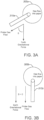
- FIG. 2 is a diagram that illustrates a sampling probe used to divert a sample of a gas stream containing particulate matter for evaluating the concentration of the particulate matter in the gas stream according to some embodiments of the inventive concept.
- a stack or duct 205 has a gas that flows therethrough and contains PM 210.
- a sampling probe 215 comprises a first portion that extends inside the wall of the duct 205 where the gas flow is carried in the inner chamber of the duct.
- the end of the first portion of the sampling probe 215 includes a nozzle that is designed to divert a sample of the gas flow including the PM into the sampling probe 215.
- the sampling probe 215 further comprises a second portion that extends from the wall of the duct 205 opposite the inner chamber.
- the first portion and second portion of the sampling probe 215 cooperate to transport the sample of the gas flow to the particulate matter analysis component 225, which is configured to evaluate the concentration of the PM in the sample of the gas stream.
- an angle ⁇ formed by a ray corresponding to the direction of the gas flow through the second portion of the sampling probe 215 and a ray corresponding to the direction of the earth's gravitational force is less than 90 degrees. That is, the sampling probe 215 is configured to take advantage of the earth's gravitational pull to ensure that PM flows down the slope of the sampling probe 215 towards the particulate matter analysis component 225.
- the particulate matter analysis component 225 including the PM detector or detection device, is positioned lower relative to the sampling probe 215 with respect to the earth's sea level.
- the angle ⁇ may be adjusted to reduce the amount of PM that is trapped in the sampling probe 215.
- larger size PM has a higher saltation velocity, which may benefit from the sampling probe 215 having a steeper slope.
- the angle ⁇ is less than 80 degrees and in other embodiments, the angle ⁇ is less than 45 degrees.
- At least a portion of the first portion of the sampling probe 215, which is disposed in the inner chamber of the duct 205, may direct the sample of the gas stream in the same direction as the second portion of the sampling probe 215 thereby having the same angular relationship with the earth's gravitational force.
- FIG. 2 illustrates a duct or stack 205 that is configured to with a vertical gas flow, i.e., opposite the direction of the earth's gravitational force.
- a vertical gas flow i.e., opposite the direction of the earth's gravitational force.
- the duct or stack transports the gas stream containing the PM in other directions.
- the duct or stack 305a transports the gas stream containing the PM in a direction into the paper that is substantially perpendicular to the direction of the earth's gravitational force.
- the sampling probe 315a may be configured similarly to that of the sampling probe 215 of FIG.
- the duct or stack 305b also transports the gas stream containing the PM in a direction into the paper that is substantially perpendicular to the direction of the earth's gravitational force.
- the sampling probe 315b is configured so as to transport that sampled gas stream in a direction that is substantially parallel to a direction of the earth's gravitational force.
- the angle ⁇ formed by a ray corresponding to the direction of the gas flow through the second portion of the sampling probe 315b and a ray corresponding to the direction of the earth's gravitational force is approximately 0 degrees.
- FIG. 4 is a block diagram of the sampling probe and the particulate matter analysis component according to some embodiments of the inventive concept.
- the PM sampling probe 415 is coupled to a particulate matter analysis component 425, which is coupled to an outlet probe 455.
- the PM sampling probe 415 may be embodied as the sampling probe 215 described above.
- the PM sampling probe 415 is configured to extend into a gas stream carried through the inner chamber of a duct or stack and divert a sample of the gas stream to the particulate matter analysis component 425 to evaluate the concentration of the PM in the stream.
- the particulate matter analysis component 425 may include various modules that can manipulate the sampled gas stream to prepare the gas stream for the detector 450. As shown in FIG.
- the particulate matter analysis component 425 comprises a heater/vaporizer module 430, a dilution module 435, a water spray module 440, and an air pulse module 445.
- the heater/vaporizer module 430 may be configured to remove moisture from the sample of the gas stream before the sample of the gas stream is provided to the detector module 450.
- the dilution module 435 may be configured to dilute the concentration of the PM in the sample of the gas stream before the sample of the gas stream is provided to the detector module 450.
- the water spray module 440 is configured to add moisture to the sample of the gas stream before the sample of the gas stream is provided to the detector module 450.
- the air pulse module 445 is configured to push the sample of the gas stream with pulses of air to adjust a velocity of the sample of the gas stream before the sample of the gas stream is provided to the detector module 450.
- These various modules may apply their functionality at various points in the path between the collection of the sampled gas stream from the duct or stack until the sampled gas stream reaches the detector module 450. The point of addition may depend, for example, on the specific application. Moreover, these modules may be used in concert with the slope angle of the PM sampling probe 415 to reduce the amount of PM that is lost in the sampling probe 415 or other elements of the particulate matter analysis component 425 before the sampled gas is provided to the detector 450.
- the heater/vaporizer module 430 may be used to ensure that any water droplets are removed before the sampled gas reaches the detector 450 for a determination of the PM concentration. But the heat and cyclonic action of the heater/vaporizer module 430 may cause some PM to impact the sidewalls of the cyclonic heater/vaporizer unit, which may cause these particles to be lost. As a result, the system may be designed to reduce the amount of additional PM that is lost from the stream in other elements of the system. For example, the slope of the sampling probe may be increased to take advantage of the earth's gravitational pull in transporting PM to the particulate matter analysis module 435. The air pulse module 445 may be used to ensure the velocity of the PM in the sampled gas stream does not fall below the saltation velocity.
- any of the techniques may be applied to the sampled gas stream with a goal to ensure that the gas stream provided to the detector module 450 is substantially devoid of water particles.
- the detector module 450 determines the concentration of the PM in the sampled stream without filters, then some of the techniques may be used depending on the application. For example, certain techniques, such as air dilution via the dilution module 435, may result in the sampled gas stream having a PM concentration that is below a detectable level depending on the technology used in the detector module 450.
- the detector module 450 may determine the concentration of the PM in the sampled gas stream in various ways in accordance with different embodiments of the inventive concept.
- the detector module 450 may perform at least one of a scattered light measurement analysis on the sampled gas stream and a transmissiometry analysis on the sampled gas stream.
- Scattered light measurement analysis is a technique in which a light sender transmits light, which is scattered in the gas stream by the particles and recorded by a sensitive receiver.
- Transmissiometry analysis is a technique in which light shines through a mixture of gas and particles whose intensity is weakened by the particles. The more particles are located in the light beam, the more the light is weakened.
- the particulate matter analysis component 425 provides the sampled gas stream to the outlet probe 455, which is configured to return the sampled gas stream to the duct or stack.
- Embodiments of the inventive concept may provide a PM sampling probe that can ensure that the sampled gas stream that is presented to a detector for analysis of the PM concentration is more representative of the stream flowing through inner chamber of the duct or stack from which the sample was obtained. This may be achieved through use of particular angles, system velocities, and techniques that reduce the loss of PM in both the sampling probe and the particulate matter analysis component.
Landscapes
- Health & Medical Sciences (AREA)
- Life Sciences & Earth Sciences (AREA)
- Chemical & Material Sciences (AREA)
- Biochemistry (AREA)
- Physics & Mathematics (AREA)
- Analytical Chemistry (AREA)
- General Health & Medical Sciences (AREA)
- General Physics & Mathematics (AREA)
- Immunology (AREA)
- Pathology (AREA)
- Engineering & Computer Science (AREA)
- Biomedical Technology (AREA)
- Molecular Biology (AREA)
- Dispersion Chemistry (AREA)
- Sampling And Sample Adjustment (AREA)
Claims (13)
- Eine Vorrichtung, die Folgendes umfasst:eine Probenahmesonde (215), die einen ersten Abschnitt und einen zweiten Abschnitt aufweist, wobei der erste Abschnitt dazu konfiguriert ist, in eine Wand einer Röhre (205), die eine Innenkammer aufweist, einzudringen, die dazu konfiguriert ist, einen Gasstrom, der Schwebstoff (210) enthält, dort hindurch zu führen, wobei der Gasstrom eine Schwebstoffkonzentration aufweist, wobei der erste Abschnitt ferner dazu konfiguriert ist, eine Probe des Gasstroms, der die genannte Schwebstoffkonzentration aufweist, von der Innenkammer der Röhre (205) an den zweiten Abschnitt umzuleiten, der sich von der Wand der Röhre (205) entgegengesetzt zur Innenkammer erstreckt;wobei der zweite Abschnitt der Probenahmesonde (215) dazu konfiguriert ist, die Probe des Gasstroms in eine erste Richtung zu leiten, wobei eine zweite Richtung einer Richtung der Anziehungskraft der Erde entspricht;wobei der Gasstrom, bei Verwendung, in der Röhre (205) in einer der Richtung der Anziehungskraft der Erde entgegengesetzten dritten Richtung in der Innenkammer wandert, und die dritte Richtung daher der zweiten Richtung entgegengesetzt ist;wobei ein erster Strahl, der der ersten Richtung entspricht, einen Winkel β mit einem zweiten Strahl, der der zweiten Richtung entspricht, bildet; undwobei der Winkel β kleiner als 90 Grad ist.
- Die Vorrichtung nach Anspruch 1, die ferner Folgendes umfasst:
eine Schwebstoffanalysekomponente (225), die dazu konfiguriert ist, die Probe des Gasstroms von dem zweiten Abschnitt der Probenahmesonde (215) zu empfangen, und ein Detektormodul umfasst, das dazu konfiguriert ist, die Konzentration des Schwebstoffs in der Probe des Gasstroms zu bestimmen. - Die Vorrichtung nach Anspruch 2, wobei der Detektor dazu konfiguriert ist, mindestens eine von einer Streulichtmessungsanalyse an der Probe des Gasstroms und einer Transmissiometrieanalyse an der Probe des Gasstroms durchzuführen.
- Die Vorrichtung nach Anspruch 2, wobei die Schwebstoffanalysekomponente ferner mindestens eines von einem Heizungs-/Verdampfermodul (430), einem Verdünnungsmodul (435), einem Wassersprühmodul (440) und einem Luftimpulsmodul (445) umfasst.
- Die Vorrichtung nach Anspruch 4, wobei das Heizungs-/Verdampfermodul (430) dazu konfiguriert ist, Feuchtigkeit von der Probe des Gasstroms zu entfernen, bevor die Probe des Gasstroms dem Detektormodul bereitgestellt wird;und/oder das Verdünnungsmodul (435) dazu konfiguriert ist, die Konzentration des Schwebstoffs in der Probe des Gasstroms zu verdünnen, bevor die Probe des Gasstroms dem Detektormodul bereitgestellt wird;und/oder das Wassersprühmodul (440) dazu konfiguriert ist, der Probe des Gasstroms Feuchtigkeit hinzuzufügen, bevor die Probe des Gasstroms dem Detektormodul bereitgestellt wird;und/oder das Luftimpulsmodul (445) dazu konfiguriert ist, die Probe des Gasstroms mit Impulsen von Luft zu treiben, um eine Geschwindigkeit der Probe des Gasstroms anzupassen, bevor die Probe des Gasstroms dem Detektormodul bereitgestellt wird.
- Die Vorrichtung nach Anspruch 2, die ferner eine Austrittssonde (455) umfasst, die dazu konfiguriert ist, die Probe der Gasstromausgabe von der Schwebstoffanalysekomponente an die Röhre zurückzuführen.
- Die Vorrichtung nach einem vorhergehenden Anspruch, wobei die Probenahmesonde (215) eine Düse einschließt, die dazu konstruiert ist, eine Probe des Gasstroms, der den Schwebstoff einschließt, in die Probenahmesonde (215) umzuleiten.
- Ein Verfahren, das Folgendes umfasst:Umleiten einer Probe eines Gasstroms, der eine Schwebstoffkonzentration aufweist, von einer Innenkammer einer Röhre (205) unter Verwendung einer Probenahmesonde (215), wobei die Innenkammer der Röhre dazu konfiguriert ist, den Gasstrom, der den Schwebstoff (210) enthält, dort hindurch zu führen, und die Schwebstoffkonzentration aufweist aufweist, wobei die Probenahmesonde (215) einen ersten Abschnitt, der dazu konfiguriert ist, in eine Wand der Röhre (205) zu der Innenkammer einzudringen, und einen zweiten Abschnitt, der sich von der Wand der Röhre (205) Gesetz zu der Innenkammer erstreckt, aufweist; undBestimmen der Konzentration des Schwebstoffs in der Probe des Gasstroms;wobei der zweite Abschnitt der Probenahmesonde (215) dazu konfiguriert ist, die Probe des Gasstroms in eine erste Richtung zu leiten, wobei eine zweite Richtung einer Richtung der Anziehungskraft der Erde entspricht;wobei der Gasstrom in der Röhre (205) in einer der Richtung der Anziehungskraft der Erde entgegengesetzten dritten Richtung in der Innenkammer wandert, und die dritte Richtung daher der zweiten Richtung entgegengesetzt ist;wobei ein erster Strahl, der der ersten Richtung entspricht, einen Winkel β mit einem zweiten Strahl, der der zweiten Richtung entspricht, bildet; undwobei der Winkel β kleiner als 90 Grad ist.
- Das Verfahren nach Anspruch 8, das ferner Folgendes umfasst:
Durchführen mindestens einer von einer Streulichtmessungsanalyse an der Probe des Gasstroms und einer Transmissiometrieanalyse an der Probe des Gasstroms. - Das Verfahren nach Anspruch 8, das ferner Folgendes umfasst:
Entfernen von Feuchtigkeit von der Probe des Gasstroms vor dem Bestimmen der Konzentration des Schwebstoffs in der Probe des Gasstroms. - Das Verfahren nach Anspruch 8, das ferner Folgendes umfasst:
Verdünnen der Konzentration des Schwebstoffs in der Probe des Gasstroms vor dem Bestimmen der Konzentration des Schwebstoffs in der Probe des Gasstroms. - Das Verfahren nach Anspruch 8, das ferner Folgendes umfasst:
Hinzufügen von Feuchtigkeit zu der Probe des Gasstroms vor dem Bestimmen der Konzentration des Schwebstoffs in der Probe des Gasstroms. - Das Verfahren nach Anspruch 8, das ferner Folgendes umfasst: Treiben der Probe des Gasstroms mit Impulsen von Luft, um eine Geschwindigkeit der Probe des Gasstroms anzupassen, vor dem Bestimmen der Konzentration des Schwebstoffs in der Probe des Gasstroms.
Applications Claiming Priority (2)
| Application Number | Priority Date | Filing Date | Title |
|---|---|---|---|
| US201662337653P | 2016-05-17 | 2016-05-17 | |
| PCT/US2017/033050 WO2017201136A1 (en) | 2016-05-17 | 2017-05-17 | Sampling probe apparatus for collecting a sample of a gas stream containing particulate matter and method of using the same |
Publications (2)
| Publication Number | Publication Date |
|---|---|
| EP3433596A1 EP3433596A1 (de) | 2019-01-30 |
| EP3433596B1 true EP3433596B1 (de) | 2024-08-21 |
Family
ID=58794171
Family Applications (1)
| Application Number | Title | Priority Date | Filing Date |
|---|---|---|---|
| EP17726424.9A Active EP3433596B1 (de) | 2016-05-17 | 2017-05-17 | Probenahmevorrichtung zur entnahme einer probe eines gasstroms mit teilchenförmigem material und verfahren zur verwendung davon |
Country Status (4)
| Country | Link |
|---|---|
| US (1) | US10551284B2 (de) |
| EP (1) | EP3433596B1 (de) |
| PL (1) | PL3433596T3 (de) |
| WO (1) | WO2017201136A1 (de) |
Families Citing this family (1)
| Publication number | Priority date | Publication date | Assignee | Title |
|---|---|---|---|---|
| CN110631970B (zh) * | 2019-09-16 | 2022-07-26 | 合肥福瞳光电科技有限公司 | 动态加热系统及大气超细颗粒物检测仪 |
Citations (11)
| Publication number | Priority date | Publication date | Assignee | Title |
|---|---|---|---|---|
| US2461584A (en) * | 1944-06-14 | 1949-02-15 | Smidth & Co As F L | Air separation method for slurry separation |
| US2753246A (en) * | 1951-06-30 | 1956-07-03 | Standard Oil Co | Continuous carbon-on-catalyst analyzer |
| US4657667A (en) * | 1984-04-05 | 1987-04-14 | The University Of Toronto Innovations Foundation | Particle classifier |
| DD277378A3 (de) * | 1987-07-01 | 1990-04-04 | Freiberg Brennstoffinst | Verfahren und Vorrichtung zur Entspannung von Dampf-Gas-Gemischen für Analysenzwecke |
| JPH0915118A (ja) * | 1995-06-30 | 1997-01-17 | Kanebo Ltd | チップ乾燥機等に用いるサンプリング装置 |
| JPH09318501A (ja) * | 1996-06-03 | 1997-12-12 | Sony Corp | 粉体のサンプリング装置 |
| US5975309A (en) * | 1996-04-18 | 1999-11-02 | Kawasaki Jukogyo Kabushiki Kaisha | Fluidized-bed classifier |
| US6151953A (en) * | 1998-01-27 | 2000-11-28 | Rupprecht & Patashnick Company, Inc. | Gas stream conditioning apparatus, system and method for use in measuring particulate matter |
| EP1516660A2 (de) * | 2003-09-19 | 2005-03-23 | GE Jenbacher GmbH & Co. OHG | Adsorbereinrichtung |
| US20100315638A1 (en) * | 2009-05-12 | 2010-12-16 | Goohs Kevin J | Particulate detection and calibration of sensors |
| WO2015127208A1 (en) * | 2014-02-21 | 2015-08-27 | 1/1Duke University | Hyperpolarized noble gas production systems with nanocluster suppression, detection and/or filtering and related methods and devices |
Family Cites Families (3)
| Publication number | Priority date | Publication date | Assignee | Title |
|---|---|---|---|---|
| US3784902A (en) | 1971-12-08 | 1974-01-08 | Ikor Inc | Apparatus for sensing particulate matter |
| US4034611A (en) | 1976-12-03 | 1977-07-12 | The United States Of America As Represented By The Secretary Of The Navy | Particulate sampling probe |
| US6481299B2 (en) | 2001-03-23 | 2002-11-19 | Avl North America Inc. | Particulate sampling probe and dilution tunnel |
-
2017
- 2017-05-17 EP EP17726424.9A patent/EP3433596B1/de active Active
- 2017-05-17 PL PL17726424.9T patent/PL3433596T3/pl unknown
- 2017-05-17 WO PCT/US2017/033050 patent/WO2017201136A1/en not_active Ceased
- 2017-05-17 US US15/597,526 patent/US10551284B2/en active Active
Patent Citations (11)
| Publication number | Priority date | Publication date | Assignee | Title |
|---|---|---|---|---|
| US2461584A (en) * | 1944-06-14 | 1949-02-15 | Smidth & Co As F L | Air separation method for slurry separation |
| US2753246A (en) * | 1951-06-30 | 1956-07-03 | Standard Oil Co | Continuous carbon-on-catalyst analyzer |
| US4657667A (en) * | 1984-04-05 | 1987-04-14 | The University Of Toronto Innovations Foundation | Particle classifier |
| DD277378A3 (de) * | 1987-07-01 | 1990-04-04 | Freiberg Brennstoffinst | Verfahren und Vorrichtung zur Entspannung von Dampf-Gas-Gemischen für Analysenzwecke |
| JPH0915118A (ja) * | 1995-06-30 | 1997-01-17 | Kanebo Ltd | チップ乾燥機等に用いるサンプリング装置 |
| US5975309A (en) * | 1996-04-18 | 1999-11-02 | Kawasaki Jukogyo Kabushiki Kaisha | Fluidized-bed classifier |
| JPH09318501A (ja) * | 1996-06-03 | 1997-12-12 | Sony Corp | 粉体のサンプリング装置 |
| US6151953A (en) * | 1998-01-27 | 2000-11-28 | Rupprecht & Patashnick Company, Inc. | Gas stream conditioning apparatus, system and method for use in measuring particulate matter |
| EP1516660A2 (de) * | 2003-09-19 | 2005-03-23 | GE Jenbacher GmbH & Co. OHG | Adsorbereinrichtung |
| US20100315638A1 (en) * | 2009-05-12 | 2010-12-16 | Goohs Kevin J | Particulate detection and calibration of sensors |
| WO2015127208A1 (en) * | 2014-02-21 | 2015-08-27 | 1/1Duke University | Hyperpolarized noble gas production systems with nanocluster suppression, detection and/or filtering and related methods and devices |
Also Published As
| Publication number | Publication date |
|---|---|
| PL3433596T3 (pl) | 2025-01-20 |
| US10551284B2 (en) | 2020-02-04 |
| US20170336302A1 (en) | 2017-11-23 |
| EP3433596A1 (de) | 2019-01-30 |
| WO2017201136A1 (en) | 2017-11-23 |
Similar Documents
| Publication | Publication Date | Title |
|---|---|---|
| JP6475882B2 (ja) | フィルタバイパス | |
| EP1987498B1 (de) | Inline-rauch-dämpfungsglied | |
| CN103608853B (zh) | 颗粒探测的方法、系统以及降低误报发生率的方法 | |
| Bergmans et al. | Particulate matter indoors: a strategy to sample and monitor size-selective fractions | |
| JP2001502417A (ja) | 空気で運ばれる有害な繊維の検出 | |
| EP3433596B1 (de) | Probenahmevorrichtung zur entnahme einer probe eines gasstroms mit teilchenförmigem material und verfahren zur verwendung davon | |
| CA2568932C (en) | Cyclonic separator with secondary vortex break | |
| AU2012201531B2 (en) | In-line smoke attenuator | |
| US4179934A (en) | Method and apparatus for monitoring particle sizes | |
| CN106290085A (zh) | 一种基于粒径的栅格分级筛选空气中颗粒物的方法和装置 | |
| CN106092669A (zh) | 一种基于粒径的栅格分级分离空气中颗粒物的方法和装置 | |
| Wedding | Ambient aerosol sampling. History, present thinking, and a proposed inlet for inhalable particulate matter | |
| Kenny et al. | Aspiration and sampling efficiencies of the TSP and louvered particulate matter inlets | |
| Schroeder et al. | Design and testing of a recirculating dust removal loop for high-temperature particle receivers | |
| Haglund et al. | Evaluation of a high volume aerosol concentrator | |
| Sehmel | Evaluation of a high-volume cascade particle impactor system | |
| US11085861B1 (en) | Apparatus for real-time size-distributed measurement of aerosol mass concentration | |
| Villanueva García | Particulate matter indoors: A strategy to sample and monitor size-selective fractions | |
| Marple et al. | History of Virtual Impactors | |
| Marple et al. | A PM1. 0/2.5/10 trichotomous virtual impactor based sampler: design and applied to arid southwest aerosols part I: design | |
| Wiegleb | Dust Measurement Technology | |
| Lobo et al. | Particle size analysis of material removed during CO 2 laser scabbling of concrete for filtration design | |
| Morris et al. | Aerosol extraction and direct laser ablation ICP-MS analysis of the fine and ultrafine fractions of regolith | |
| Yule et al. | Experimental study of virtual impactors | |
| Papastefanou | Aerosol sampling and measurement techniques |
Legal Events
| Date | Code | Title | Description |
|---|---|---|---|
| STAA | Information on the status of an ep patent application or granted ep patent |
Free format text: STATUS: UNKNOWN |
|
| STAA | Information on the status of an ep patent application or granted ep patent |
Free format text: STATUS: THE INTERNATIONAL PUBLICATION HAS BEEN MADE |
|
| PUAI | Public reference made under article 153(3) epc to a published international application that has entered the european phase |
Free format text: ORIGINAL CODE: 0009012 |
|
| STAA | Information on the status of an ep patent application or granted ep patent |
Free format text: STATUS: REQUEST FOR EXAMINATION WAS MADE |
|
| 17P | Request for examination filed |
Effective date: 20181027 |
|
| AK | Designated contracting states |
Kind code of ref document: A1 Designated state(s): AL AT BE BG CH CY CZ DE DK EE ES FI FR GB GR HR HU IE IS IT LI LT LU LV MC MK MT NL NO PL PT RO RS SE SI SK SM TR |
|
| AX | Request for extension of the european patent |
Extension state: BA ME |
|
| DAV | Request for validation of the european patent (deleted) | ||
| DAX | Request for extension of the european patent (deleted) | ||
| STAA | Information on the status of an ep patent application or granted ep patent |
Free format text: STATUS: EXAMINATION IS IN PROGRESS |
|
| 17Q | First examination report despatched |
Effective date: 20211125 |
|
| GRAP | Despatch of communication of intention to grant a patent |
Free format text: ORIGINAL CODE: EPIDOSNIGR1 |
|
| STAA | Information on the status of an ep patent application or granted ep patent |
Free format text: STATUS: GRANT OF PATENT IS INTENDED |
|
| INTG | Intention to grant announced |
Effective date: 20231017 |
|
| GRAJ | Information related to disapproval of communication of intention to grant by the applicant or resumption of examination proceedings by the epo deleted |
Free format text: ORIGINAL CODE: EPIDOSDIGR1 |
|
| STAA | Information on the status of an ep patent application or granted ep patent |
Free format text: STATUS: EXAMINATION IS IN PROGRESS |
|
| GRAP | Despatch of communication of intention to grant a patent |
Free format text: ORIGINAL CODE: EPIDOSNIGR1 |
|
| STAA | Information on the status of an ep patent application or granted ep patent |
Free format text: STATUS: GRANT OF PATENT IS INTENDED |
|
| INTC | Intention to grant announced (deleted) | ||
| INTG | Intention to grant announced |
Effective date: 20240315 |
|
| GRAS | Grant fee paid |
Free format text: ORIGINAL CODE: EPIDOSNIGR3 |
|
| GRAA | (expected) grant |
Free format text: ORIGINAL CODE: 0009210 |
|
| STAA | Information on the status of an ep patent application or granted ep patent |
Free format text: STATUS: THE PATENT HAS BEEN GRANTED |
|
| AK | Designated contracting states |
Kind code of ref document: B1 Designated state(s): AL AT BE BG CH CY CZ DE DK EE ES FI FR GB GR HR HU IE IS IT LI LT LU LV MC MK MT NL NO PL PT RO RS SE SI SK SM TR |
|
| P01 | Opt-out of the competence of the unified patent court (upc) registered |
Free format text: CASE NUMBER: APP_41357/2024 Effective date: 20240712 |
|
| REG | Reference to a national code |
Ref country code: GB Ref legal event code: FG4D |
|
| REG | Reference to a national code |
Ref country code: CH Ref legal event code: EP |
|
| REG | Reference to a national code |
Ref country code: IE Ref legal event code: FG4D |
|
| REG | Reference to a national code |
Ref country code: DE Ref legal event code: R096 Ref document number: 602017084237 Country of ref document: DE |
|
| REG | Reference to a national code |
Ref country code: LT Ref legal event code: MG9D |
|
| REG | Reference to a national code |
Ref country code: NL Ref legal event code: MP Effective date: 20240821 |
|
| PG25 | Lapsed in a contracting state [announced via postgrant information from national office to epo] |
Ref country code: NO Free format text: LAPSE BECAUSE OF FAILURE TO SUBMIT A TRANSLATION OF THE DESCRIPTION OR TO PAY THE FEE WITHIN THE PRESCRIBED TIME-LIMIT Effective date: 20241121 |
|
| REG | Reference to a national code |
Ref country code: AT Ref legal event code: MK05 Ref document number: 1715924 Country of ref document: AT Kind code of ref document: T Effective date: 20240821 |
|
| PG25 | Lapsed in a contracting state [announced via postgrant information from national office to epo] |
Ref country code: NL Free format text: LAPSE BECAUSE OF FAILURE TO SUBMIT A TRANSLATION OF THE DESCRIPTION OR TO PAY THE FEE WITHIN THE PRESCRIBED TIME-LIMIT Effective date: 20240821 Ref country code: FI Free format text: LAPSE BECAUSE OF FAILURE TO SUBMIT A TRANSLATION OF THE DESCRIPTION OR TO PAY THE FEE WITHIN THE PRESCRIBED TIME-LIMIT Effective date: 20240821 Ref country code: PT Free format text: LAPSE BECAUSE OF FAILURE TO SUBMIT A TRANSLATION OF THE DESCRIPTION OR TO PAY THE FEE WITHIN THE PRESCRIBED TIME-LIMIT Effective date: 20241223 Ref country code: GR Free format text: LAPSE BECAUSE OF FAILURE TO SUBMIT A TRANSLATION OF THE DESCRIPTION OR TO PAY THE FEE WITHIN THE PRESCRIBED TIME-LIMIT Effective date: 20241122 |
|
| PG25 | Lapsed in a contracting state [announced via postgrant information from national office to epo] |
Ref country code: BG Free format text: LAPSE BECAUSE OF FAILURE TO SUBMIT A TRANSLATION OF THE DESCRIPTION OR TO PAY THE FEE WITHIN THE PRESCRIBED TIME-LIMIT Effective date: 20240821 |
|
| PG25 | Lapsed in a contracting state [announced via postgrant information from national office to epo] |
Ref country code: LV Free format text: LAPSE BECAUSE OF FAILURE TO SUBMIT A TRANSLATION OF THE DESCRIPTION OR TO PAY THE FEE WITHIN THE PRESCRIBED TIME-LIMIT Effective date: 20240821 |
|
| PG25 | Lapsed in a contracting state [announced via postgrant information from national office to epo] |
Ref country code: AT Free format text: LAPSE BECAUSE OF FAILURE TO SUBMIT A TRANSLATION OF THE DESCRIPTION OR TO PAY THE FEE WITHIN THE PRESCRIBED TIME-LIMIT Effective date: 20240821 Ref country code: IS Free format text: LAPSE BECAUSE OF FAILURE TO SUBMIT A TRANSLATION OF THE DESCRIPTION OR TO PAY THE FEE WITHIN THE PRESCRIBED TIME-LIMIT Effective date: 20241221 |
|
| PG25 | Lapsed in a contracting state [announced via postgrant information from national office to epo] |
Ref country code: HR Free format text: LAPSE BECAUSE OF FAILURE TO SUBMIT A TRANSLATION OF THE DESCRIPTION OR TO PAY THE FEE WITHIN THE PRESCRIBED TIME-LIMIT Effective date: 20240821 |
|
| PG25 | Lapsed in a contracting state [announced via postgrant information from national office to epo] |
Ref country code: RS Free format text: LAPSE BECAUSE OF FAILURE TO SUBMIT A TRANSLATION OF THE DESCRIPTION OR TO PAY THE FEE WITHIN THE PRESCRIBED TIME-LIMIT Effective date: 20241121 Ref country code: ES Free format text: LAPSE BECAUSE OF FAILURE TO SUBMIT A TRANSLATION OF THE DESCRIPTION OR TO PAY THE FEE WITHIN THE PRESCRIBED TIME-LIMIT Effective date: 20240821 |
|
| PG25 | Lapsed in a contracting state [announced via postgrant information from national office to epo] |
Ref country code: RS Free format text: LAPSE BECAUSE OF FAILURE TO SUBMIT A TRANSLATION OF THE DESCRIPTION OR TO PAY THE FEE WITHIN THE PRESCRIBED TIME-LIMIT Effective date: 20241121 Ref country code: PT Free format text: LAPSE BECAUSE OF FAILURE TO SUBMIT A TRANSLATION OF THE DESCRIPTION OR TO PAY THE FEE WITHIN THE PRESCRIBED TIME-LIMIT Effective date: 20241223 Ref country code: NO Free format text: LAPSE BECAUSE OF FAILURE TO SUBMIT A TRANSLATION OF THE DESCRIPTION OR TO PAY THE FEE WITHIN THE PRESCRIBED TIME-LIMIT Effective date: 20241121 Ref country code: NL Free format text: LAPSE BECAUSE OF FAILURE TO SUBMIT A TRANSLATION OF THE DESCRIPTION OR TO PAY THE FEE WITHIN THE PRESCRIBED TIME-LIMIT Effective date: 20240821 Ref country code: LV Free format text: LAPSE BECAUSE OF FAILURE TO SUBMIT A TRANSLATION OF THE DESCRIPTION OR TO PAY THE FEE WITHIN THE PRESCRIBED TIME-LIMIT Effective date: 20240821 Ref country code: IS Free format text: LAPSE BECAUSE OF FAILURE TO SUBMIT A TRANSLATION OF THE DESCRIPTION OR TO PAY THE FEE WITHIN THE PRESCRIBED TIME-LIMIT Effective date: 20241221 Ref country code: HR Free format text: LAPSE BECAUSE OF FAILURE TO SUBMIT A TRANSLATION OF THE DESCRIPTION OR TO PAY THE FEE WITHIN THE PRESCRIBED TIME-LIMIT Effective date: 20240821 Ref country code: GR Free format text: LAPSE BECAUSE OF FAILURE TO SUBMIT A TRANSLATION OF THE DESCRIPTION OR TO PAY THE FEE WITHIN THE PRESCRIBED TIME-LIMIT Effective date: 20241122 Ref country code: FI Free format text: LAPSE BECAUSE OF FAILURE TO SUBMIT A TRANSLATION OF THE DESCRIPTION OR TO PAY THE FEE WITHIN THE PRESCRIBED TIME-LIMIT Effective date: 20240821 Ref country code: ES Free format text: LAPSE BECAUSE OF FAILURE TO SUBMIT A TRANSLATION OF THE DESCRIPTION OR TO PAY THE FEE WITHIN THE PRESCRIBED TIME-LIMIT Effective date: 20240821 Ref country code: BG Free format text: LAPSE BECAUSE OF FAILURE TO SUBMIT A TRANSLATION OF THE DESCRIPTION OR TO PAY THE FEE WITHIN THE PRESCRIBED TIME-LIMIT Effective date: 20240821 Ref country code: AT Free format text: LAPSE BECAUSE OF FAILURE TO SUBMIT A TRANSLATION OF THE DESCRIPTION OR TO PAY THE FEE WITHIN THE PRESCRIBED TIME-LIMIT Effective date: 20240821 |
|
| PG25 | Lapsed in a contracting state [announced via postgrant information from national office to epo] |
Ref country code: DK Free format text: LAPSE BECAUSE OF FAILURE TO SUBMIT A TRANSLATION OF THE DESCRIPTION OR TO PAY THE FEE WITHIN THE PRESCRIBED TIME-LIMIT Effective date: 20240821 Ref country code: RO Free format text: LAPSE BECAUSE OF FAILURE TO SUBMIT A TRANSLATION OF THE DESCRIPTION OR TO PAY THE FEE WITHIN THE PRESCRIBED TIME-LIMIT Effective date: 20240821 Ref country code: SM Free format text: LAPSE BECAUSE OF FAILURE TO SUBMIT A TRANSLATION OF THE DESCRIPTION OR TO PAY THE FEE WITHIN THE PRESCRIBED TIME-LIMIT Effective date: 20240821 |
|
| PG25 | Lapsed in a contracting state [announced via postgrant information from national office to epo] |
Ref country code: EE Free format text: LAPSE BECAUSE OF FAILURE TO SUBMIT A TRANSLATION OF THE DESCRIPTION OR TO PAY THE FEE WITHIN THE PRESCRIBED TIME-LIMIT Effective date: 20240821 |
|
| PG25 | Lapsed in a contracting state [announced via postgrant information from national office to epo] |
Ref country code: CZ Free format text: LAPSE BECAUSE OF FAILURE TO SUBMIT A TRANSLATION OF THE DESCRIPTION OR TO PAY THE FEE WITHIN THE PRESCRIBED TIME-LIMIT Effective date: 20240821 |
|
| PG25 | Lapsed in a contracting state [announced via postgrant information from national office to epo] |
Ref country code: SK Free format text: LAPSE BECAUSE OF FAILURE TO SUBMIT A TRANSLATION OF THE DESCRIPTION OR TO PAY THE FEE WITHIN THE PRESCRIBED TIME-LIMIT Effective date: 20240821 |
|
| REG | Reference to a national code |
Ref country code: DE Ref legal event code: R097 Ref document number: 602017084237 Country of ref document: DE |
|
| PLBE | No opposition filed within time limit |
Free format text: ORIGINAL CODE: 0009261 |
|
| STAA | Information on the status of an ep patent application or granted ep patent |
Free format text: STATUS: NO OPPOSITION FILED WITHIN TIME LIMIT |
|
| PGFP | Annual fee paid to national office [announced via postgrant information from national office to epo] |
Ref country code: DE Payment date: 20250423 Year of fee payment: 9 |
|
| PGFP | Annual fee paid to national office [announced via postgrant information from national office to epo] |
Ref country code: IT Payment date: 20250428 Year of fee payment: 9 |
|
| 26N | No opposition filed |
Effective date: 20250522 |
|
| PG25 | Lapsed in a contracting state [announced via postgrant information from national office to epo] |
Ref country code: SE Free format text: LAPSE BECAUSE OF FAILURE TO SUBMIT A TRANSLATION OF THE DESCRIPTION OR TO PAY THE FEE WITHIN THE PRESCRIBED TIME-LIMIT Effective date: 20240821 |
|
| REG | Reference to a national code |
Ref country code: CH Ref legal event code: H13 Free format text: ST27 STATUS EVENT CODE: U-0-0-H10-H13 (AS PROVIDED BY THE NATIONAL OFFICE) Effective date: 20251223 |
|
| PG25 | Lapsed in a contracting state [announced via postgrant information from national office to epo] |
Ref country code: LU Free format text: LAPSE BECAUSE OF NON-PAYMENT OF DUE FEES Effective date: 20250517 |
|
| PG25 | Lapsed in a contracting state [announced via postgrant information from national office to epo] |
Ref country code: CH Free format text: LAPSE BECAUSE OF NON-PAYMENT OF DUE FEES Effective date: 20250531 |
|
| REG | Reference to a national code |
Ref country code: BE Ref legal event code: MM Effective date: 20250531 |
|
| PG25 | Lapsed in a contracting state [announced via postgrant information from national office to epo] |
Ref country code: MC Free format text: LAPSE BECAUSE OF FAILURE TO SUBMIT A TRANSLATION OF THE DESCRIPTION OR TO PAY THE FEE WITHIN THE PRESCRIBED TIME-LIMIT Effective date: 20240821 |
|
| PGFP | Annual fee paid to national office [announced via postgrant information from national office to epo] |
Ref country code: GB Payment date: 20260312 Year of fee payment: 10 |
|
| PG25 | Lapsed in a contracting state [announced via postgrant information from national office to epo] |
Ref country code: IE Free format text: LAPSE BECAUSE OF NON-PAYMENT OF DUE FEES Effective date: 20250517 |
|
| PG25 | Lapsed in a contracting state [announced via postgrant information from national office to epo] |
Ref country code: BE Free format text: LAPSE BECAUSE OF NON-PAYMENT OF DUE FEES Effective date: 20250531 |
|
| PG25 | Lapsed in a contracting state [announced via postgrant information from national office to epo] |
Ref country code: FR Free format text: LAPSE BECAUSE OF NON-PAYMENT OF DUE FEES Effective date: 20250531 |