EP3433128B1 - Siege de vehicule comportant un dispositif de guidage d'une sangle - Google Patents
Siege de vehicule comportant un dispositif de guidage d'une sangle Download PDFInfo
- Publication number
- EP3433128B1 EP3433128B1 EP17710777.8A EP17710777A EP3433128B1 EP 3433128 B1 EP3433128 B1 EP 3433128B1 EP 17710777 A EP17710777 A EP 17710777A EP 3433128 B1 EP3433128 B1 EP 3433128B1
- Authority
- EP
- European Patent Office
- Prior art keywords
- seat
- branches
- strap
- guiding device
- base
- Prior art date
- Legal status (The legal status is an assumption and is not a legal conclusion. Google has not performed a legal analysis and makes no representation as to the accuracy of the status listed.)
- Active
Links
Images

Classifications
-
- B—PERFORMING OPERATIONS; TRANSPORTING
- B60—VEHICLES IN GENERAL
- B60N—SEATS SPECIALLY ADAPTED FOR VEHICLES; VEHICLE PASSENGER ACCOMMODATION NOT OTHERWISE PROVIDED FOR
- B60N2/00—Seats specially adapted for vehicles; Arrangement or mounting of seats in vehicles
- B60N2/58—Seat coverings
- B60N2/60—Removable protective coverings
- B60N2/6009—Removable protective coverings covering more than only the seat
-
- B—PERFORMING OPERATIONS; TRANSPORTING
- B60—VEHICLES IN GENERAL
- B60N—SEATS SPECIALLY ADAPTED FOR VEHICLES; VEHICLE PASSENGER ACCOMMODATION NOT OTHERWISE PROVIDED FOR
- B60N2/00—Seats specially adapted for vehicles; Arrangement or mounting of seats in vehicles
- B60N2/58—Seat coverings
- B60N2/60—Removable protective coverings
-
- B—PERFORMING OPERATIONS; TRANSPORTING
- B60—VEHICLES IN GENERAL
- B60N—SEATS SPECIALLY ADAPTED FOR VEHICLES; VEHICLE PASSENGER ACCOMMODATION NOT OTHERWISE PROVIDED FOR
- B60N2/00—Seats specially adapted for vehicles; Arrangement or mounting of seats in vehicles
- B60N2/58—Seat coverings
- B60N2/60—Removable protective coverings
- B60N2/6018—Removable protective coverings attachments thereof
- B60N2/6081—Removable protective coverings attachments thereof by adhesion, e.g. glueing
-
- B—PERFORMING OPERATIONS; TRANSPORTING
- B60—VEHICLES IN GENERAL
- B60N—SEATS SPECIALLY ADAPTED FOR VEHICLES; VEHICLE PASSENGER ACCOMMODATION NOT OTHERWISE PROVIDED FOR
- B60N2205/00—General mechanical or structural details
- B60N2205/40—Dual or redundant actuating means, e.g. backrest tilting can be actuated alternatively by a lever at the backrest or a lever in the luggage compartment
Definitions
- the present invention relates to a device for guiding a control strap passing through a flexible wall whose actuation makes it possible to disengage a mechanism capable of unlocking a seat from its slides in order to ensure its sliding or its extraction from the vehicle.
- FR2911305 which describes a mechanism for locking and unlocking a seat on the floor of the passenger compartment of a vehicle.
- the mechanism comprising an unlocking lever and means for actuating the lever mechanically connected to said unlocking lever by a link so as, on the one hand, to actuate the unlocking of the seat and the closure fixing system and, on the other hand, to ensure gripping the seat.
- the mechanism is arranged under the seat structure, the lever being graspable from the rear of the seat at the level of a protective element. This mechanism constitutes a rigid assembly and does not pass through a flexible wall.
- the control strap passes through a slot to pass through a flexible wall whose actuation makes it possible to disengage a mechanism capable of unlocking a seat.
- a mechanism capable of unlocking a seat we understand that if the draw of the strap is performed obliquely, the friction of the strap of the strap in the slot of the flexible wall can progressively deteriorate it and the JPH075892U discloses a vehicle seat comprising a backrest and a seat secured to a base mounted on runners fixed to the floor and an unlocking control means passing through a flexible wall masking the rear of the base, the seat comprising a rigid guide device of the control means.
- the object of the invention is therefore to propose a device for guiding the strap of a pulling strap in an imperfect direction, passing through a flexible wall through a dedicated slot, guaranteeing to keep intact said flexible wall disposed behind the structure of the seat of a seat, to provide an integrity perceived quality.
- the subject of the present invention is a vehicle seat comprising a backrest and a seat secured to a base mounted on runners fixed to the floor and an unlocking control means passing through a flexible wall masking the rear of the base.
- the seat comprising a rigid guide device for the control means, placed behind the flexible wall, the guide device has a structure forming a pin comprising branches of equal length.
- the structure of the guide device is a rigid cylindrical wire.
- the cylindrical wire is metallic.
- the branches of the guide device are parallel to the level of the passage of the control means.
- the branches approach each other towards their ends.
- the end of the branches is introduced into a bore in the side wall of the base and opens onto the other face of the side wall.
- the ends of the branches are secured to the wall of the base by a weld bead.
- the branches are positioned horizontally and located in a vertical plane.
- the guide device is attached to the flexible wall.
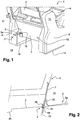
- the figure 1 is a rear perspective view of the passenger compartment 11 of a vehicle showing the backrest 3 and the seat 6 of the seats 1 comprising a control means 5.
- the control means 5 consists of a strap 5a extended by a strap 2.
- Seat 1 comprises a base 12 consisting of two side walls 8, 9 covered with linings 10 and connected together by tubular elements (not visible) to ensure the mechanical strength.
- This base 12 is surmounted by a horizontal seat 6 and the substantially vertical backrest 3.
- the rear of the base 12 disposed between the two side walls 8, 9 is hidden by the flexible wall 7 of protection ensuring good perceived quality.
- the base 12 includes a clean guide mechanism to slide in slides 14 formed in the floor 15 of the vehicle. To move the seat 1 on its slides 14 or to extract it from the vehicle, the guide mechanisms are unlocked.
- control means 5 consisting of the strap 5a extended by the strap 2 is provided at the rear of the seat 1, the strap 2 passing through a slot 18 in the flexible wall 7.
- Manual pulling of the strap 5a rear control disengages the mechanisms capable of performing the unlocking of the seat 1. It is understood that if the pulling of the strap 5a is carried out obliquely, the friction of the strap 2 of the strap 5a in the slot 18 of the flexible wall 7 should gradually deteriorate and tear it.
- the disengaging of the mechanisms makes it possible either to move the seat 1 longitudinally on its slide 14, or in order to extract it from the vehicle to increase storage space.
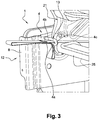
- the figure 2 is an enlarged schematic overview of profile showing the location of the guide device 4 of a strap 5a in a rear seat space 1, mounted in the passenger compartment 11 of a vehicle, according to the invention.
- the flexible wall 7 of the seat 1 is shown in section at the level of the strap 5a.
- the strap 2 extending the strap 5a passes through the slot 18 formed in the flexible wall 7 and the guide device 4 symbolized in the form of two cylindrical branches 4a, 4b for connecting to the other end 2c of the strap 2 to a mechanism of unlocking not shown.
- the guide device 4 is rigid.
- the two branches 4a, 4b of cylindrical sections are formed in the form of metallic cylindrical son 13 on which the strap 2 of the strap 5a can slide freely on the generatrix of the branches 4a, 4b.
- the guide device 4 is attached to the flexible wall 7 and the center of the cylindrical branches 4a, 4b is arranged on an axis 19 parallel to the flexible wall 7. It is understood that the slot 18 has a width slightly greater than the axis two son 13 so as not to touch the flexible wall 7, if the strap 2 is actuated obliquely. 5a automatic strap recall system is provided to return it to its initial position. To this end, an additional loop 20 of the strap 2 comes into positive abutment because of its thickness against the wire 13 of the branches 4a, 4b whose space between the generatrices is less than the thickness of said loop 20.
- the figure 3 is a partial perspective view showing the rear of the base 12 of the seat of a seat 1 deprived of its flexible wall 7 comprising a guide device 4 of a strap 5a according to the invention.
- the base 12 includes the side walls 8, 9 (visible figure 1 ) interconnected by tubular elements 25 to form a robust assembly.
- This base 12 is surmounted by the frame 21 of the seat 13 of the seat 1.
- the guide device 4 is constituted by a wire 13 in a pin comprising two branches 4a, 4b whose cylindrical sections are identical and connected together by a part of curved branch 4c of 180 degrees.
- the strap 2 of the strap 5a is introduced between the branches 4a, 4b of the guide device 4.
- the branches 4a, 4b are mutually parallel at the level of the passage of the strap 2 of the strap 5a.
- the end of the branches 4a, 4b is fixed in the side wall 8.
- the figure 4 is an enlarged partial perspective view of three quarter front showing the guide device 4 of a strap 5a according to the invention, comprising the two branches 4a, 4b and the curved branch part 4c forming a pin in order to prevent the strap 2 from moving laterally.
- the lower branch 4a is rectilinear while the upper branch 4b is parallel to the branch 4a at the passage of the strap 2 and beyond approaches the lower branch 4a to extend parallel so that their ends are introduced into openings cylindrical 22 made in the wall 8 for their fastenings.
- the loop 20 is obtained by the continuity of the end 5c of the strap 5a obtained using the strap 2 folded over on themselves, the end of which is folded over the strap 2 after formation of the said loop 20, in order to provide triple thickness.
- a reinforcement 23 of the width of the strap 2 is provided at the junction of these thicknesses which are sewn by resistant cords 25 between them to generate a point of blocking of the strap 5a in the passage between the branches 4a, 4b of the device guidance 4.
- the figure 5 is an enlarged partial perspective view of the rear of the guide device 4 of a strap 5a showing its attachment to the base 12 of the seat 1, according to the invention.
- the ends of the branches 4a, 4b are introduced into openings cylindrical 22 adjusted to the diameter of the metal wire 13, in the wall 8 of the base 12 of the seat 1.
- the ends of the branches 4a, 4b protrude on the opposite face of the wall 8.
- a weld bead 24 firmly secures the end of the branches 4a, 4b of the guide device 4 on the wall 8 of the base 12 of the seat 1.
Landscapes
- Engineering & Computer Science (AREA)
- Aviation & Aerospace Engineering (AREA)
- Transportation (AREA)
- Mechanical Engineering (AREA)
- Seats For Vehicles (AREA)
Description
- La présente invention concerne un dispositif de guidage d'une sangle de commande traversant une paroi souple dont l'actionnement permet de débrayer un mécanisme apte à effectuer le déverrouillage d'un siège de ses glissières en vue d'assurer son coulissement ou son extraction du véhicule.
- Dans l'état de la technique, nous connaissons le document
FR2911305 JPH075892U - Le but de l'invention est donc de proposer un dispositif de guidage de la lanière d'une sangle de tirage suivant une direction imparfaite, traversant une paroi souple à travers une fente dédiée, garantissant de conserver intact ladite paroi souple disposée derrière la structure de l'assise d'un siège, pour fournir une qualité perçue irréprochable.
- A cet effet, la présente invention a pour objet un siège de véhicule comportant un dossier et une assise solidaire d'un socle monté sur des glissières fixées sur le plancher et un moyen de commande de déverrouillage traversant une paroi souple masquant l'arrière du socle, le siège comprenant un dispositif de guidage rigide du moyen de commande, placé derrière la paroi souple, le dispositif de guidage possède une structure formant une épingle comportant des branches de longueur égales.
- Suivant une autre caractéristique avantageuse, la structure du dispositif de guidage est un fil cylindrique rigide.
- Avantageusement, le fil cylindrique est métallique.
- Selon une variante, les branches du dispositif de guidage sont parallèles au niveau du passage du moyen de commande.
- Selon une autre variante, les branches se rapprochent l'une de l'autre vers leurs extrémités.
- Selon une autre variante, l'extrémité des branches est introduite dans un perçage de la paroi latérale du socle et débouche sur l'autre face de la paroi latérale.
- Avantageusement, l'extrémité des branches sont solidarisées à la paroi du socle par un cordon de soudure.
- Selon une autre caractéristique, les branches sont positionnées horizontalement et situées dans un plan vertical.
- Avantageusement, le dispositif de guidage est accolé à la paroi souple.
- D'autres caractéristiques et avantages de l'invention apparaîtront clairement à la lecture de la description ci-après, donnée à titre indicatif en référence aux dessins annexés dans lesquels:
- La
figure 1 est une vue arrière en perspective dans l'habitacle d'un véhicule montrant le dossier des sièges comportant des sangles dont la lanière traverse une paroi souple ; - La
figure 2 est une vue d'ensemble schématique de profil montrant l'implantation du dispositif de guidage d'une sangle dans un espace de siège arrière, monté dans l'habitacle d'un véhicule, suivant l'invention ; - La
figure 3 est une vue en perspective montrant l'arrière de la structure de l'assise d'un siège démuni de sa paroi souple comportant un dispositif de guidage d'une sangle suivant l'invention ; - La
figure 4 est une vue en perspective partielle agrandie de trois quart avant montrant le dispositif de guidage d'une sangle suivant l'invention ; - La
figure 5 est une vue en perspective partielle agrandie de l'arrière du dispositif de guidage d'une sangle montrant sa fixation sur la structure du siège, suivant l'invention. - La
figure 1 est une vue arrière en perspective de l'habitacle 11 d'un véhicule montrant le dossier 3 et l'assise 6 des sièges 1 comportant un moyen de commande 5. Le moyen de commande 5 est constitué d'une sangle 5a prolongée par une lanière 2. Le siège 1 comprend un socle 12 constituée de deux parois latérales 8, 9 recouvertes de garnitures 10 et reliées entre elles par des éléments tubulaires (non visible) permettant d'assurer la tenue mécanique. Ce socle 12 est surmontée par une assise horizontale 6 et le dossier sensiblement vertical 3. L'arrière du socle 12 disposée entre les deux parois latérales 8, 9 est masquée par la paroi souple 7 de protection assurant une bonne qualité perçue. Le socle 12 comporte un mécanisme de guidage propre à coulisser dans des glissières 14 ménagées dans le plancher 15 du véhicule. Pour déplacer le siège 1 sur ses glissières 14 ou encore pour l'extraire du véhicule, les mécanismes de guidage sont déverrouillés. A cet effet, le moyen de commande 5 constitué de la sangle 5a prolongée par la lanière 2 est prévue à l'arrière du siège 1, la lanière 2 passant à travers une fente 18 de la paroi souple 7. Le tirage manuel de la sangle 5a de commande vers l'arrière permet de débrayer les mécanismes aptes à effectuer le déverrouillage du siège 1. On comprend que si le tirage de la sangle 5a est effectué obliquement, le frottement de la lanière 2 de la sangle 5a dans la fente 18 de la paroi souple 7 devrait progressivement la détériorer et la déchirer. Le débrayage des mécanismes permet soit de déplacer le siège 1 longitudinalement sur sa glissière 14, soit en vue de l'extraire du véhicule afin d'augmenter l'espace de stockage. - La
figure 2 est une vue d'ensemble schématique agrandie de profil montrant l'implantation du dispositif de guidage 4 d'une sangle 5a dans un espace de siège 1 arrière, monté dans l'habitacle 11 d'un véhicule, suivant l'invention. La paroi souple 7 du siège 1 est représentée en coupe au niveau de la sangle 5a. La lanière 2 prolongeant la sangle 5a traverse la fente 18 ménagée dans la paroi souple 7 et le dispositif de guidage 4 symbolisé sous forme de deux branches cylindriques 4a, 4b pour se raccorder à l'autre extrémité 2c de la lanière 2 à un mécanisme de déverrouillage non représenté. Le dispositif de guidage 4 est rigide. Les deux branches 4a, 4b de sections cylindriques sont constituées sous forme de fils cylindrique 13 métallique sur laquelle la lanière 2 de la sangle 5a peut glisser librement sur la génératrice des branches 4a, 4b. Le dispositif de guidage 4 est accolé à la paroi souple 7 et le centre des branches cylindriques 4a, 4b est disposé sur un axe 19 parallèle à la paroi souple 7. On comprend que la fente 18 possède une largeur légèrement supérieur à l'entre axe des deux fils 13 de manière à ne pas effleurer la paroi souple 7, si la lanière 2 est actionnée obliquement. Un système de rappel automatique de la sangle 5a est prévu pour la replacer dans sa position initiale. A cet effet, une boucle 20 additionnelle de la lanière 2 vient en butée positive du fait de son épaisseur contre le fil 13 des branches 4a, 4b dont l'espace entre les génératrices est inférieure à l'épaisseur de la dite boucle 20. - La
figure 3 est une vue partielle en perspective montrant l'arrière du socle 12 de l'assise d'un siège 1 démuni de sa paroi souple 7 comportant un dispositif de guidage 4 d'une sangle 5a suivant l'invention. Le socle 12 comprend les parois latérales 8, 9 (visiblefigure 1 ) reliées entre elles par des éléments tubulaires 25 pour constituer un ensemble robuste. Ce socle 12 est surmonté par l'armature 21 de l'assise 13 du siège 1. Le dispositif de guidage 4 est constitué par un fil 13 en épingle comportant deux branches 4a, 4b dont les sections cylindriques sont identiques et reliées entre elles par une partie de branche courbée 4c de 180 degrés. La lanière 2 de la sangle 5a est introduite entre les branches 4a, 4b du dispositif de guidage 4. En particulier, les branches 4a, 4b sont parallèles entre elles au niveau du passage de la lanière 2 de la sangle 5a. L'extrémité des branches 4a, 4b vient se fixer dans la paroi latérale 8. - La
figure 4 est une vue en perspective partielle agrandie de trois quart avant montrant le dispositif de guidage 4 d'une sangle 5a suivant l'invention, comprenant les deux branches 4a, 4b et la partie de branche courbe 4c formant une épingle afin d'éviter à la lanière 2 de se déplacer latéralement. La branche inférieure 4a est rectiligne tandis que la branche supérieure 4b est parallèle à la branche 4a au niveau du passage de la lanière 2 et au-delà se rapproche de la branche inférieure 4a pour se prolonger parallèlement afin que leurs extrémités soient introduites dans des ouvertures cylindriques 22 réalisées dans la paroi 8 pour leurs fixations. La boucle 20 est obtenue par la continuité de l'extrémité 5c de la sangle 5a obtenue à l'aide de la lanière 2 repliée sur elles même dont l'extrémité est repliée sur la lanière 2 après formation de la dite boucle 20, afin de fournir une triple épaisseur. Un renfort 23 de la largeur de la lanière 2 est prévu à la jonction de ces épaisseurs qui sont couseuses par des cordons résistants 25 entre elles pour générer un point de blocage de la sangle 5a dans le passage entre les branches 4a, 4b du dispositif de guidage 4. - La
figure 5 est une vue en perspective partielle agrandie de l'arrière du dispositif de guidage 4 d'une sangle 5a montrant sa fixation sur le socle 12 du siège 1, suivant l'invention. Les extrémités des branches 4a, 4b sont introduites dans des ouvertures cylindriques 22 ajustées au diamètre du fil métallique 13, dans la paroi 8 du socle 12 du siège 1. Les extrémités des branches 4a, 4b sont en saillie sur la face opposée de la paroi 8. Un cordon 24 de soudure vient solidariser fermement l'extrémité des branches 4a, 4b du dispositif de guidage 4 sur la paroi 8 du socle 12 du siège 1.
Claims (9)
- Siège (1) de véhicule comportant un dossier (3) et une assise (6) solidaire d'un socle (12) monté sur des glissières (14) fixées sur le plancher (15) et un moyen de commande de déverrouillage traversant une paroi souple (7) masquant l'arrière du socle (12), caractérisé en ce que le siège (1) comprend un dispositif de guidage (4) rigide du moyen de commande (5), placé derrière la paroi souple (7), et en ce que le dispositif de guidage (4) possède une structure formant une épingle comportant des branches (4a, 4b) de longueur égales.
- Siège (1) selon la revendication 1, caractérisé en ce que la structure du dispositif de guidage (4) est un fil cylindrique (13) rigide.
- Siège (1) selon la revendication 2, caractérisé en ce que le fil cylindrique (13) est métallique.
- Siège (1) selon la revendication 1, caractérisée en ce que les branches (4a, 4b) du dispositif de guidage (4) sont parallèles au niveau du passage du moyen de commande (5).
- Siège (1) selon l'une quelconque des revendications 1 ou 4, caractérisé en ce que les branches (4a, 4b) se rapprochent l'une de l'autre vers leurs extrémités.
- Siège (1) selon la revendication 5, caractérisé en ce que l'extrémité des branches (4a, 4b) est introduite dans un perçage (22) de la paroi latérale (8) du socle (12) et débouche sur l'autre face de la paroi latérale (8).
- Siège (1) selon l'une quelconque des revendications 5 ou 6, caractérisé en ce que l'extrémité des branches (4a, 4b) est solidarisée à la paroi du socle (12) par un cordon de soudure (24) .
- Siège (1) selon l'une quelconque des revendications 1 et 4 à 7, caractérisé en ce que les branches (4a, 4b) sont positionnées horizontalement et situées dans un plan vertical.
- Siège (1) selon l'une quelconque des revendications 1 ou 2, caractérisé en ce que le dispositif de guidage (4) est accolé à la paroi souple (7).
Applications Claiming Priority (2)
| Application Number | Priority Date | Filing Date | Title |
|---|---|---|---|
| FR1652628A FR3049240B1 (fr) | 2016-03-25 | 2016-03-25 | Siege de vehicule comportant un dispositif de guidage d’une sangle. |
| PCT/FR2017/050336 WO2017162938A1 (fr) | 2016-03-25 | 2017-02-14 | Siege de vehicule comportant un dispositif de guidage d'une sangle |
Publications (2)
| Publication Number | Publication Date |
|---|---|
| EP3433128A1 EP3433128A1 (fr) | 2019-01-30 |
| EP3433128B1 true EP3433128B1 (fr) | 2020-01-22 |
Family
ID=55953291
Family Applications (1)
| Application Number | Title | Priority Date | Filing Date |
|---|---|---|---|
| EP17710777.8A Active EP3433128B1 (fr) | 2016-03-25 | 2017-02-14 | Siege de vehicule comportant un dispositif de guidage d'une sangle |
Country Status (4)
| Country | Link |
|---|---|
| EP (1) | EP3433128B1 (fr) |
| FR (1) | FR3049240B1 (fr) |
| RU (1) | RU2745750C2 (fr) |
| WO (1) | WO2017162938A1 (fr) |
Family Cites Families (5)
| Publication number | Priority date | Publication date | Assignee | Title |
|---|---|---|---|---|
| JPH075892U (ja) * | 1993-06-28 | 1995-01-27 | 池田物産株式会社 | 車両用シート |
| RU2309858C1 (ru) * | 2006-06-06 | 2007-11-10 | Общество с ограниченной ответственностью "Слафт" | Салазка механизма продольного перемещения сиденья |
| JP4627519B2 (ja) * | 2006-07-11 | 2011-02-09 | 本田技研工業株式会社 | 引張り具の支持構造 |
| FR2911305B1 (fr) | 2007-01-16 | 2010-02-26 | Renault Sas | Siege avec moyens de reglage pour vehicule automobile |
| JP5778026B2 (ja) * | 2011-12-29 | 2015-09-16 | 株式会社タチエス | 自動車に用いる折りたたみシート |
-
2016
- 2016-03-25 FR FR1652628A patent/FR3049240B1/fr not_active Expired - Fee Related
-
2017
- 2017-02-14 RU RU2018137483A patent/RU2745750C2/ru active
- 2017-02-14 WO PCT/FR2017/050336 patent/WO2017162938A1/fr not_active Ceased
- 2017-02-14 EP EP17710777.8A patent/EP3433128B1/fr active Active
Non-Patent Citations (1)
| Title |
|---|
| None * |
Also Published As
| Publication number | Publication date |
|---|---|
| EP3433128A1 (fr) | 2019-01-30 |
| RU2018137483A3 (fr) | 2020-05-26 |
| RU2018137483A (ru) | 2020-04-27 |
| FR3049240A1 (fr) | 2017-09-29 |
| FR3049240B1 (fr) | 2018-03-23 |
| RU2745750C2 (ru) | 2021-03-31 |
| WO2017162938A1 (fr) | 2017-09-28 |
Similar Documents
| Publication | Publication Date | Title |
|---|---|---|
| FR2684934A1 (fr) | Siege mobile pour vehicule. | |
| FR2458462A1 (fr) | Dispositif de variation du pas des sieges dans les avions commerciaux | |
| FR2890378A1 (fr) | Capot de nacelle pour turboreacteur et nacelle comportant au moins un tel capot. | |
| FR2929185A1 (fr) | Dispositif a double effet pour la commande d'un support coulissant d'appuie-tete de siege de vehicule automobile | |
| FR3003889A1 (fr) | Porte souple | |
| FR2851967A1 (fr) | Ensemble comprenant une base et une console mobile par coulissement et extractible par rapport a la base et vehicule automobile correspondant | |
| WO2017162938A1 (fr) | Siege de vehicule comportant un dispositif de guidage d'une sangle | |
| FR3035625A1 (fr) | Systeme de montage d'appui-tete et siege de vehicule | |
| EP2137026B1 (fr) | Siege pour vehicule automobile convertible en siege enfant dos a la route et vehicule automobile associe | |
| EP0368735B1 (fr) | Profil de glissières permettant la réalisation de glissières à verrou flottant | |
| EP0995641B1 (fr) | Dispositif de protection tel que filet de protection pour vehicule automobile | |
| EP1852309A1 (fr) | Dispositif cache-bagages pour véhicule automobile, à ouverture partielle automatique, et véhicule automobile correspondant. | |
| FR2929186A1 (fr) | Dispositif de commande d'un support coulissant equipant un appuie-tete pour siege de vehicule automobile | |
| FR2879139A1 (fr) | Dispositif de reglage longitudinal de la position d'un element, partie d'assise ou de dossier constitutif d'un siege automobile pour enfant | |
| EP0749868A1 (fr) | Dispositif de liaison articulée entre le dossier et l'assise d'un siège de véhicule | |
| EP0965478A1 (fr) | Siège arrière réglable en position longitudinale dans un habitacle de véhicule automobile | |
| WO2023007475A1 (fr) | Dossier de siège de véhicule muni d' un dispositif de coussin gonflable de sécurité et siège de véhicule comprenant un tel dossier | |
| FR2463024A1 (fr) | Banquette arriere de vehicule | |
| FR2599319A1 (fr) | Dispositif de protection du conducteur d'un vehicule contre les agressions par des passagers. | |
| EP2690245A1 (fr) | Dispositif de tulipe et coulisse de guidage pour volet roulant | |
| FR2810591A1 (fr) | Toit ouvrant en toile pour vehicule automobile | |
| FR2967621A1 (fr) | Goulotte de guidage de cables pour le montage de vehicules automobiles | |
| FR2741849A1 (fr) | Agencement d'une ceinture de securite a enrouleur pour la place centrale d'une banquette arriere de vehicule automobile | |
| EP3661804B1 (fr) | Dispositif de protection d'un occupant d'un siege de vehicule vis a vis d'un systeme d'inclinaison du dossier d'un tel siege et procede de fixation d'un tel dispositif | |
| FR3083497A1 (fr) | Procede et dispositif de positionnement d’une boucle de ceinture de securite via un passage d’un siege de vehicule |
Legal Events
| Date | Code | Title | Description |
|---|---|---|---|
| STAA | Information on the status of an ep patent application or granted ep patent |
Free format text: STATUS: UNKNOWN |
|
| STAA | Information on the status of an ep patent application or granted ep patent |
Free format text: STATUS: THE INTERNATIONAL PUBLICATION HAS BEEN MADE |
|
| PUAI | Public reference made under article 153(3) epc to a published international application that has entered the european phase |
Free format text: ORIGINAL CODE: 0009012 |
|
| STAA | Information on the status of an ep patent application or granted ep patent |
Free format text: STATUS: REQUEST FOR EXAMINATION WAS MADE |
|
| 17P | Request for examination filed |
Effective date: 20180803 |
|
| AK | Designated contracting states |
Kind code of ref document: A1 Designated state(s): AL AT BE BG CH CY CZ DE DK EE ES FI FR GB GR HR HU IE IS IT LI LT LU LV MC MK MT NL NO PL PT RO RS SE SI SK SM TR |
|
| AX | Request for extension of the european patent |
Extension state: BA ME |
|
| DAV | Request for validation of the european patent (deleted) | ||
| DAX | Request for extension of the european patent (deleted) | ||
| GRAP | Despatch of communication of intention to grant a patent |
Free format text: ORIGINAL CODE: EPIDOSNIGR1 |
|
| STAA | Information on the status of an ep patent application or granted ep patent |
Free format text: STATUS: GRANT OF PATENT IS INTENDED |
|
| INTG | Intention to grant announced |
Effective date: 20190816 |
|
| GRAS | Grant fee paid |
Free format text: ORIGINAL CODE: EPIDOSNIGR3 |
|
| GRAA | (expected) grant |
Free format text: ORIGINAL CODE: 0009210 |
|
| STAA | Information on the status of an ep patent application or granted ep patent |
Free format text: STATUS: THE PATENT HAS BEEN GRANTED |
|
| AK | Designated contracting states |
Kind code of ref document: B1 Designated state(s): AL AT BE BG CH CY CZ DE DK EE ES FI FR GB GR HR HU IE IS IT LI LT LU LV MC MK MT NL NO PL PT RO RS SE SI SK SM TR |
|
| REG | Reference to a national code |
Ref country code: GB Ref legal event code: FG4D Free format text: NOT ENGLISH |
|
| REG | Reference to a national code |
Ref country code: CH Ref legal event code: EP |
|
| REG | Reference to a national code |
Ref country code: DE Ref legal event code: R096 Ref document number: 602017010935 Country of ref document: DE |
|
| REG | Reference to a national code |
Ref country code: DE Ref legal event code: R084 Ref document number: 602017010935 Country of ref document: DE |
|
| REG | Reference to a national code |
Ref country code: AT Ref legal event code: REF Ref document number: 1226718 Country of ref document: AT Kind code of ref document: T Effective date: 20200215 |
|
| REG | Reference to a national code |
Ref country code: IE Ref legal event code: FG4D Free format text: LANGUAGE OF EP DOCUMENT: FRENCH |
|
| REG | Reference to a national code |
Ref country code: GB Ref legal event code: 746 Effective date: 20200227 |
|
| REG | Reference to a national code |
Ref country code: NL Ref legal event code: MP Effective date: 20200122 |
|
| REG | Reference to a national code |
Ref country code: LT Ref legal event code: MG4D |
|
| PG25 | Lapsed in a contracting state [announced via postgrant information from national office to epo] |
Ref country code: RS Free format text: LAPSE BECAUSE OF FAILURE TO SUBMIT A TRANSLATION OF THE DESCRIPTION OR TO PAY THE FEE WITHIN THE PRESCRIBED TIME-LIMIT Effective date: 20200122 Ref country code: NL Free format text: LAPSE BECAUSE OF FAILURE TO SUBMIT A TRANSLATION OF THE DESCRIPTION OR TO PAY THE FEE WITHIN THE PRESCRIBED TIME-LIMIT Effective date: 20200122 Ref country code: PT Free format text: LAPSE BECAUSE OF FAILURE TO SUBMIT A TRANSLATION OF THE DESCRIPTION OR TO PAY THE FEE WITHIN THE PRESCRIBED TIME-LIMIT Effective date: 20200614 Ref country code: FI Free format text: LAPSE BECAUSE OF FAILURE TO SUBMIT A TRANSLATION OF THE DESCRIPTION OR TO PAY THE FEE WITHIN THE PRESCRIBED TIME-LIMIT Effective date: 20200122 Ref country code: NO Free format text: LAPSE BECAUSE OF FAILURE TO SUBMIT A TRANSLATION OF THE DESCRIPTION OR TO PAY THE FEE WITHIN THE PRESCRIBED TIME-LIMIT Effective date: 20200422 |
|
| PG25 | Lapsed in a contracting state [announced via postgrant information from national office to epo] |
Ref country code: LV Free format text: LAPSE BECAUSE OF FAILURE TO SUBMIT A TRANSLATION OF THE DESCRIPTION OR TO PAY THE FEE WITHIN THE PRESCRIBED TIME-LIMIT Effective date: 20200122 Ref country code: SE Free format text: LAPSE BECAUSE OF FAILURE TO SUBMIT A TRANSLATION OF THE DESCRIPTION OR TO PAY THE FEE WITHIN THE PRESCRIBED TIME-LIMIT Effective date: 20200122 Ref country code: GR Free format text: LAPSE BECAUSE OF FAILURE TO SUBMIT A TRANSLATION OF THE DESCRIPTION OR TO PAY THE FEE WITHIN THE PRESCRIBED TIME-LIMIT Effective date: 20200423 Ref country code: BG Free format text: LAPSE BECAUSE OF FAILURE TO SUBMIT A TRANSLATION OF THE DESCRIPTION OR TO PAY THE FEE WITHIN THE PRESCRIBED TIME-LIMIT Effective date: 20200422 Ref country code: IS Free format text: LAPSE BECAUSE OF FAILURE TO SUBMIT A TRANSLATION OF THE DESCRIPTION OR TO PAY THE FEE WITHIN THE PRESCRIBED TIME-LIMIT Effective date: 20200522 Ref country code: HR Free format text: LAPSE BECAUSE OF FAILURE TO SUBMIT A TRANSLATION OF THE DESCRIPTION OR TO PAY THE FEE WITHIN THE PRESCRIBED TIME-LIMIT Effective date: 20200122 |
|
| REG | Reference to a national code |
Ref country code: CH Ref legal event code: PL |
|
| REG | Reference to a national code |
Ref country code: DE Ref legal event code: R097 Ref document number: 602017010935 Country of ref document: DE |
|
| REG | Reference to a national code |
Ref country code: BE Ref legal event code: MM Effective date: 20200229 |
|
| PG25 | Lapsed in a contracting state [announced via postgrant information from national office to epo] |
Ref country code: SK Free format text: LAPSE BECAUSE OF FAILURE TO SUBMIT A TRANSLATION OF THE DESCRIPTION OR TO PAY THE FEE WITHIN THE PRESCRIBED TIME-LIMIT Effective date: 20200122 Ref country code: EE Free format text: LAPSE BECAUSE OF FAILURE TO SUBMIT A TRANSLATION OF THE DESCRIPTION OR TO PAY THE FEE WITHIN THE PRESCRIBED TIME-LIMIT Effective date: 20200122 Ref country code: SM Free format text: LAPSE BECAUSE OF FAILURE TO SUBMIT A TRANSLATION OF THE DESCRIPTION OR TO PAY THE FEE WITHIN THE PRESCRIBED TIME-LIMIT Effective date: 20200122 Ref country code: DK Free format text: LAPSE BECAUSE OF FAILURE TO SUBMIT A TRANSLATION OF THE DESCRIPTION OR TO PAY THE FEE WITHIN THE PRESCRIBED TIME-LIMIT Effective date: 20200122 Ref country code: LU Free format text: LAPSE BECAUSE OF NON-PAYMENT OF DUE FEES Effective date: 20200214 Ref country code: MC Free format text: LAPSE BECAUSE OF FAILURE TO SUBMIT A TRANSLATION OF THE DESCRIPTION OR TO PAY THE FEE WITHIN THE PRESCRIBED TIME-LIMIT Effective date: 20200122 Ref country code: ES Free format text: LAPSE BECAUSE OF FAILURE TO SUBMIT A TRANSLATION OF THE DESCRIPTION OR TO PAY THE FEE WITHIN THE PRESCRIBED TIME-LIMIT Effective date: 20200122 Ref country code: CZ Free format text: LAPSE BECAUSE OF FAILURE TO SUBMIT A TRANSLATION OF THE DESCRIPTION OR TO PAY THE FEE WITHIN THE PRESCRIBED TIME-LIMIT Effective date: 20200122 Ref country code: RO Free format text: LAPSE BECAUSE OF FAILURE TO SUBMIT A TRANSLATION OF THE DESCRIPTION OR TO PAY THE FEE WITHIN THE PRESCRIBED TIME-LIMIT Effective date: 20200122 Ref country code: LT Free format text: LAPSE BECAUSE OF FAILURE TO SUBMIT A TRANSLATION OF THE DESCRIPTION OR TO PAY THE FEE WITHIN THE PRESCRIBED TIME-LIMIT Effective date: 20200122 |
|
| RAP2 | Party data changed (patent owner data changed or rights of a patent transferred) |
Owner name: PSA AUTOMOBILES SA |
|
| REG | Reference to a national code |
Ref country code: AT Ref legal event code: MK05 Ref document number: 1226718 Country of ref document: AT Kind code of ref document: T Effective date: 20200122 |
|
| PLBE | No opposition filed within time limit |
Free format text: ORIGINAL CODE: 0009261 |
|
| STAA | Information on the status of an ep patent application or granted ep patent |
Free format text: STATUS: NO OPPOSITION FILED WITHIN TIME LIMIT |
|
| PG25 | Lapsed in a contracting state [announced via postgrant information from national office to epo] |
Ref country code: LI Free format text: LAPSE BECAUSE OF NON-PAYMENT OF DUE FEES Effective date: 20200229 Ref country code: CH Free format text: LAPSE BECAUSE OF NON-PAYMENT OF DUE FEES Effective date: 20200229 |
|
| 26N | No opposition filed |
Effective date: 20201023 |
|
| PG25 | Lapsed in a contracting state [announced via postgrant information from national office to epo] |
Ref country code: AT Free format text: LAPSE BECAUSE OF FAILURE TO SUBMIT A TRANSLATION OF THE DESCRIPTION OR TO PAY THE FEE WITHIN THE PRESCRIBED TIME-LIMIT Effective date: 20200122 Ref country code: IT Free format text: LAPSE BECAUSE OF FAILURE TO SUBMIT A TRANSLATION OF THE DESCRIPTION OR TO PAY THE FEE WITHIN THE PRESCRIBED TIME-LIMIT Effective date: 20200122 Ref country code: IE Free format text: LAPSE BECAUSE OF NON-PAYMENT OF DUE FEES Effective date: 20200214 |
|
| PG25 | Lapsed in a contracting state [announced via postgrant information from national office to epo] |
Ref country code: SI Free format text: LAPSE BECAUSE OF FAILURE TO SUBMIT A TRANSLATION OF THE DESCRIPTION OR TO PAY THE FEE WITHIN THE PRESCRIBED TIME-LIMIT Effective date: 20200122 Ref country code: BE Free format text: LAPSE BECAUSE OF NON-PAYMENT OF DUE FEES Effective date: 20200229 Ref country code: PL Free format text: LAPSE BECAUSE OF FAILURE TO SUBMIT A TRANSLATION OF THE DESCRIPTION OR TO PAY THE FEE WITHIN THE PRESCRIBED TIME-LIMIT Effective date: 20200122 |
|
| PG25 | Lapsed in a contracting state [announced via postgrant information from national office to epo] |
Ref country code: TR Free format text: LAPSE BECAUSE OF FAILURE TO SUBMIT A TRANSLATION OF THE DESCRIPTION OR TO PAY THE FEE WITHIN THE PRESCRIBED TIME-LIMIT Effective date: 20200122 Ref country code: MT Free format text: LAPSE BECAUSE OF FAILURE TO SUBMIT A TRANSLATION OF THE DESCRIPTION OR TO PAY THE FEE WITHIN THE PRESCRIBED TIME-LIMIT Effective date: 20200122 Ref country code: CY Free format text: LAPSE BECAUSE OF FAILURE TO SUBMIT A TRANSLATION OF THE DESCRIPTION OR TO PAY THE FEE WITHIN THE PRESCRIBED TIME-LIMIT Effective date: 20200122 |
|
| PG25 | Lapsed in a contracting state [announced via postgrant information from national office to epo] |
Ref country code: MK Free format text: LAPSE BECAUSE OF FAILURE TO SUBMIT A TRANSLATION OF THE DESCRIPTION OR TO PAY THE FEE WITHIN THE PRESCRIBED TIME-LIMIT Effective date: 20200122 Ref country code: AL Free format text: LAPSE BECAUSE OF FAILURE TO SUBMIT A TRANSLATION OF THE DESCRIPTION OR TO PAY THE FEE WITHIN THE PRESCRIBED TIME-LIMIT Effective date: 20200122 |
|
| REG | Reference to a national code |
Ref country code: DE Ref legal event code: R081 Ref document number: 602017010935 Country of ref document: DE Owner name: STELLANTIS AUTO SAS, FR Free format text: FORMER OWNER: PSA AUTOMOBILES SA, POISSY, FR |
|
| PGFP | Annual fee paid to national office [announced via postgrant information from national office to epo] |
Ref country code: GB Payment date: 20260121 Year of fee payment: 10 |
|
| PGFP | Annual fee paid to national office [announced via postgrant information from national office to epo] |
Ref country code: DE Payment date: 20260121 Year of fee payment: 10 |
|
| PGFP | Annual fee paid to national office [announced via postgrant information from national office to epo] |
Ref country code: FR Payment date: 20260121 Year of fee payment: 10 |