EP3433032B1 - High pressure cleaning lance drive safety apparatus - Google Patents
High pressure cleaning lance drive safety apparatus Download PDFInfo
- Publication number
- EP3433032B1 EP3433032B1 EP17770828.6A EP17770828A EP3433032B1 EP 3433032 B1 EP3433032 B1 EP 3433032B1 EP 17770828 A EP17770828 A EP 17770828A EP 3433032 B1 EP3433032 B1 EP 3433032B1
- Authority
- EP
- European Patent Office
- Prior art keywords
- lance
- safety apparatus
- high pressure
- valve
- flexible
- Prior art date
- Legal status (The legal status is an assumption and is not a legal conclusion. Google has not performed a legal analysis and makes no representation as to the accuracy of the status listed.)
- Active
Links
Images




Classifications
-
- B—PERFORMING OPERATIONS; TRANSPORTING
- B08—CLEANING
- B08B—CLEANING IN GENERAL; PREVENTION OF FOULING IN GENERAL
- B08B3/00—Cleaning by methods involving the use or presence of liquid or steam
- B08B3/02—Cleaning by the force of jets or sprays
-
- B—PERFORMING OPERATIONS; TRANSPORTING
- B08—CLEANING
- B08B—CLEANING IN GENERAL; PREVENTION OF FOULING IN GENERAL
- B08B9/00—Cleaning hollow articles by methods or apparatus specially adapted thereto
- B08B9/02—Cleaning pipes or tubes or systems of pipes or tubes
- B08B9/027—Cleaning the internal surfaces; Removal of blockages
- B08B9/032—Cleaning the internal surfaces; Removal of blockages by the mechanical action of a moving fluid, e.g. by flushing
- B08B9/0321—Cleaning the internal surfaces; Removal of blockages by the mechanical action of a moving fluid, e.g. by flushing using pressurised, pulsating or purging fluid
-
- F—MECHANICAL ENGINEERING; LIGHTING; HEATING; WEAPONS; BLASTING
- F16—ENGINEERING ELEMENTS AND UNITS; GENERAL MEASURES FOR PRODUCING AND MAINTAINING EFFECTIVE FUNCTIONING OF MACHINES OR INSTALLATIONS; THERMAL INSULATION IN GENERAL
- F16M—FRAMES, CASINGS OR BEDS OF ENGINES, MACHINES OR APPARATUS, NOT SPECIFIC TO ENGINES, MACHINES OR APPARATUS PROVIDED FOR ELSEWHERE; STANDS; SUPPORTS
- F16M7/00—Details of attaching or adjusting engine beds, frames, or supporting-legs on foundation or base; Attaching non-moving engine parts, e.g. cylinder blocks
-
- B—PERFORMING OPERATIONS; TRANSPORTING
- B05—SPRAYING OR ATOMISING IN GENERAL; APPLYING FLUENT MATERIALS TO SURFACES, IN GENERAL
- B05B—SPRAYING APPARATUS; ATOMISING APPARATUS; NOZZLES
- B05B13/00—Machines or plants for applying liquids or other fluent materials to surfaces of objects or other work by spraying, not covered by groups B05B1/00 - B05B11/00
- B05B13/02—Means for supporting work; Arrangement or mounting of spray heads; Adaptation or arrangement of means for feeding work
- B05B13/0278—Arrangement or mounting of spray heads
-
- B—PERFORMING OPERATIONS; TRANSPORTING
- B05—SPRAYING OR ATOMISING IN GENERAL; APPLYING FLUENT MATERIALS TO SURFACES, IN GENERAL
- B05B—SPRAYING APPARATUS; ATOMISING APPARATUS; NOZZLES
- B05B3/00—Spraying or sprinkling apparatus with moving outlet elements or moving deflecting elements
- B05B3/02—Spraying or sprinkling apparatus with moving outlet elements or moving deflecting elements with rotating elements
- B05B3/10—Spraying or sprinkling apparatus with moving outlet elements or moving deflecting elements with rotating elements discharging over substantially the whole periphery of the rotating member
-
- B—PERFORMING OPERATIONS; TRANSPORTING
- B08—CLEANING
- B08B—CLEANING IN GENERAL; PREVENTION OF FOULING IN GENERAL
- B08B9/00—Cleaning hollow articles by methods or apparatus specially adapted thereto
- B08B9/02—Cleaning pipes or tubes or systems of pipes or tubes
- B08B9/027—Cleaning the internal surfaces; Removal of blockages
- B08B9/04—Cleaning the internal surfaces; Removal of blockages using cleaning devices introduced into and moved along the pipes
- B08B9/043—Cleaning the internal surfaces; Removal of blockages using cleaning devices introduced into and moved along the pipes moved by externally powered mechanical linkage, e.g. pushed or drawn through the pipes
- B08B9/045—Cleaning the internal surfaces; Removal of blockages using cleaning devices introduced into and moved along the pipes moved by externally powered mechanical linkage, e.g. pushed or drawn through the pipes the cleaning devices being rotated while moved, e.g. flexible rotating shaft or "snake"
-
- B—PERFORMING OPERATIONS; TRANSPORTING
- B08—CLEANING
- B08B—CLEANING IN GENERAL; PREVENTION OF FOULING IN GENERAL
- B08B9/00—Cleaning hollow articles by methods or apparatus specially adapted thereto
- B08B9/08—Cleaning containers, e.g. tanks
- B08B9/093—Cleaning containers, e.g. tanks by the force of jets or sprays
- B08B9/0936—Cleaning containers, e.g. tanks by the force of jets or sprays using rotating jets
-
- F—MECHANICAL ENGINEERING; LIGHTING; HEATING; WEAPONS; BLASTING
- F16—ENGINEERING ELEMENTS AND UNITS; GENERAL MEASURES FOR PRODUCING AND MAINTAINING EFFECTIVE FUNCTIONING OF MACHINES OR INSTALLATIONS; THERMAL INSULATION IN GENERAL
- F16M—FRAMES, CASINGS OR BEDS OF ENGINES, MACHINES OR APPARATUS, NOT SPECIFIC TO ENGINES, MACHINES OR APPARATUS PROVIDED FOR ELSEWHERE; STANDS; SUPPORTS
- F16M11/00—Stands or trestles as supports for apparatus or articles placed thereon ; Stands for scientific apparatus such as gravitational force meters
- F16M11/20—Undercarriages with or without wheels
- F16M11/24—Undercarriages with or without wheels changeable in height or length of legs, also for transport only, e.g. by means of tubes screwed into each other
- F16M11/242—Undercarriages with or without wheels changeable in height or length of legs, also for transport only, e.g. by means of tubes screwed into each other by spreading of the legs
- F16M11/245—Members limiting spreading of legs, e.g. "umbrella legs"
Definitions
- the present disclosure is directed to high pressure fluid rotary nozzle handling systems.
- embodiments of the present disclosure are directed to a safety apparatus for detecting and minimizing danger to personnel from a high pressure cleaning lance inadvertently backing out of a floor or roof drain or otherwise in a situation where a back-out preventer either cannot be installed on the support structure or would be difficult to install.
- a safety apparatus that can be mounted above or about the drain or other opening that facilitates simplified handling of flexible lances together with a drive that permits an operator to stand clear of the region directly above or around the drain or other opening and which precludes uncontrolled motion of a high pressure flexible cleaning lance.
- WO 98/40175 A1 discloses a device and a method for the treatment of the inner surface of a container having an opening.
- the device comprises a treatment member which is mountable in such a position that it extends into the container (2) through said opening and which is arranged to enable said treatment by the supply of a fluid.
- the device comprises a cover arranged to close said opening and support the treatment member in said position and having a sealing surface abutting a sealing surface of the container.
- the cover comprises a drainage passage for fluid consumed.
- US 2,074,052 A discloses a flexible cleaning lance apparatus for cleaning the interior of tanks, especially tanks on shipboard designed for the transportation of oil, and is more specifically directed to the development of jetting means for cleaning solutions employed in such operations, and the use of such jetting means.
- This apparatus comprises a support structure adapted to be placed on a support surface above an opening into an object to be cleaned, and a flexible lance operable to carry a high pressure fluid to and into the object to be cleaned.
- US 2011/180111 A1 discloses a tank cleaning device, comprising a base member; a conduit attached to the base member having an inlet, an upper outlet, and a lower outlet; and a plurality of adjustable legs connected to and extending below the base member.
- the inlet of the conduit accepts a cleaning fluid
- a cleaning nozzle is attached to either the upper outlet or the lower outlet.
- the document also discloses a method of cleaning the tank, comprising placing the mounting device at a first location, spraying the tank with the cleaning fluid until a selected portion of the tank is cleaned, discontinuing the supply of cleaning fluid, and then repositioning the mounting device to a second location within the tank and resuming the supply of cleaning fluid. Multiple mounting devices may be employed and periodically repositioned within the tank.
- US 2011/062695 A1 discloses an automatic concrete pump, with stability monitoring system includes an undercarriage supportable on a subsurface by two front and two rear outriggers.
- a respective measuring element is disposed in the telescoping support legs of the outriggers for determining the supporting force.
- Each support leg has an upper telescoping element connected to the associated outrigger at an upper connection point, and a support base displaceable relative to the upper element and supported on the subsurface at the lower end thereof at a lower connection point.
- the measuring element is disposed either directly at the upper connection point between the outrigger and the upper telescoping element, or in the region of the lower connection point between the lower telescoping element and the support base.
- a flexible cleaning lance safety apparatus in accordance with claim 1 of the present disclosure directly addresses such needs.
- One exemplary flexible lance drive apparatus in accordance with the present disclosure includes a flexible lance drive device preferably mounted to the apex of a support frame such as a tripod positioned above the opening of the object to be cleaned.
- the tripod rests on a horizontal support surface such as a floor, roof or tube sheet.
- This embodiment of the apparatus has a sensor, preferably a pressure sensing air micro valve switch positioned at the foot or bottom of each tripod leg.
- Each micro valve switch operates to trigger automatic and immediate bleed-off of control air pressure in the event that the weight sensed by each support leg decreases to a predetermined value.
- the immediate bleed-off of control air pressure triggers dump, i.e. exhaust of the high pressure fluid pressure applied to a flexible cleaning lance.
- An embodiment in accordance with the present disclosure may be viewed as a flexible cleaning lance safety apparatus that includes a support structure located close to, e.g., adjacent or in registry with, an opening into an object to be cleaned, a high pressure fluid to the object to be cleaned, and one or more micro pressure valves on the support structure operative to sense a predetermined force applied between the support structure and the structure support surface. When the predetermined force is sensed, the high pressure fluid is diverted from the object to be cleaned to atmosphere.
- This support structure may be a tripod. At least one micro pressure valve is preferably mounted between the support surface supporting the tripod and each leg of the tripod.
- Each micro pressure valve is preferably connected in series with a pilot valve that is operable to quickly bleed off air pressure applied to an air pressure actuated high pressure fluid dump valve when the predetermined force is sensed.
- the tripod has a micro pressure valve mounted at a foot of each leg of the tripod.
- a snout tube is preferably mounted between the lance drive and the object to be cleaned to direct the lance and shield an operator from any fluid spray from the lance.
- the safety apparatus preferably further includes a plurality of micro pressure valves connected in series such that the force sensed at any one of the micro pressure valves reaching the predetermined force causes air pressure to one or more pilot valves to decrease.
- the one or more pilot valves operate an air actuated high pressure dump valve to divert high pressure fluid pressure applied to the flexible lance to atmosphere.
- a flexible cleaning lance safety apparatus in accordance with the present disclosure may alternatively be viewed as including a tripod support structure located close to an opening into an object to be cleaned, a flexible lance drive fastened to the support structure for driving a high pressure fluid through a lance to the object to be cleaned, and one or more micro pressure valves on each leg of the tripod support structure operative to sense a predetermined force applied between the support structure and a support surface supporting the tripod support structure. When the predetermined force is sensed, the apparatus causes the high pressure fluid to be diverted from the lance and the object to be cleaned to atmosphere.
- Each micro pressure valve is connected in series with a pilot valve operable to bleed off air pressure applied to a dump valve when the predetermined force is sensed.
- the tripod has a micro pressure valve mounted at a foot of each leg of the tripod and the micro pressure valves are preferably connected in series.
- a snout tube is preferably mounted to the tripod directing a cleaning lance from the drive to the object to be cleaned.
- a flexible cleaning lance safety apparatus in accordance with the present disclosure may be viewed as including a tripod support structure located close to an opening into an object to be cleaned, a flexible lance drive fastened to the support structure for driving a lance directing high pressure fluid to the object to be cleaned, a snout tube between the lance drive and an opening into the object to be cleaned, and one or more micro pressure valves on each leg of the tripod support structure operative to sense a predetermined force applied between the support structure and a support surface supporting the tripod support structure. When the predetermined force is sensed this causes the high pressure fluid to be diverted from the lance and the object to be cleaned to atmosphere.
- Each micro pressure valve is connected in series with a pilot valve. The pilot valve is operable to bleed off air pressure applied to an air actuated high pressure fluid dump valve when the predetermined force is sensed by the pilot valve.
- the apparatus 100 includes a flexible lance drive 110 for inserting and retracting the flexible lance vertically through a snout tube 130 that guides the lance into and out of the drain 102.
- This exemplary apparatus 100 includes a tripod support structure 120 and a guide sleeve or snout tube 130 positioned coaxially in registry with an opening into a floor drain 102.
- the support structure 120 rests on a support surface 104 such as a floor, grating, planar tube sheet or roof.
- the snout tube 130 is adjusted so as to fit within the floor drain 102 about 2 inches or more below the surface 104.
- the apparatus 100 may also include a collet block 137 between the drive 110 and the tube 130 for limiting passage of a flexible lance through the snout tube 130.
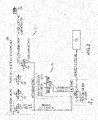
- each of the tripod feet 122 of the tripod support 120 is pressure sensor such as a push button micro pressure valve switch or simply "micro valve” 140. Air pressure circuit diagrams for these switches are shown in FIGS. 2 through 4 .
- each of these micro pressure valves 140 is connected in series to a piloted valve 150 mounted in a box 124 fastened to the apex of the tripod support structure 120. So long as each of the three micro pressure valves 140 remain pressurized, the piloted valve 150 remains open, providing a pressure signal or "on” signal to the high pressure water pressure actuator 160 on the operator's control panel (not shown in FIG. 1 ).
- Loss of this pressure in turn, via the piloted valve 150, will override an operator who may be providing an "on" signal to the high pressure water actuator 170 on the operator's control console, and automatically divert or dump high pressure water away from the flexible lance and its tool, thus providing an enhanced safety margin for the operator in the event of an unanticipated movement or tipping of the tripod support structure 120 of the safety apparatus 100 .
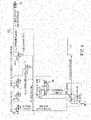
- FIG. 3 shows another embodiment of the air pressure control apparatus 100 in which an additional rapid exhaust valve 180 is present in series with the piloted valve 150.
- This fast acting valve 180 shortens the time required for the air pressure to completely exhaust thus shortening the time between sensing a tipping of the tripod support 120 and the complete shutdown of fluid flow to the lance.
- FIG 4 shows an alternative embodiment of the apparatus 100 in which two pilot valves 150 are arranged in parallel to reduce the bleed-down time of the air pressure in the event of one of the sensor micro valves 140 reaching its set point pressure.
- one or more micro valves 140 may also be mounted on the snout tube 130.
- a back-out preventer may be fastened to the snout tube 130 or to the opening into the drain 102 to prevent a flexible lance from backing out of the drain opening or other opening into a piping system or other object being cleaned.
- a back-out preventer is shown installed in FIGS. 6 and 7 .
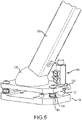
- FIG. 5 shows a close-up perspective view of the foot end of one of the tripod legs 126.
- This foot end of leg 126 may be fastened to a dome foot member or rotatably mounted to swivel joint foot which has a dome portion 128 and a flat plate portion 132.
- Plate portion 132 is spaced parallel to a flat base plate 134.
- the flat base plate 134 is the component that actually touches the support surface 104, whether it be a floor, a grate, tube sheet, or other structure.
- a plurality of screws 136 fastened to the base plate 134 each has a coil spring 138 around it that biases the plate portion 132 away from the base plate 134.
- the micro pressure valve 140 is fastened to the plate portion 132 and has a plunger 142 that presses against the upper surface of the base plate 134.
- the micro valve 140 is set such that when the baseplate 134 is fully spaced by the springs 138 from the plate portion 132, air pressure is removed from the dump actuator 160. Only when the baseplate 134 is compressed toward the plate portion 132 by the weight of the leg 126 and its portion of the apparatus 100 ultimately against the support surface 104 will micro pressure valve 140 be closed. Hence the apparatus 100 senses when it is properly resting on the support surface. Lifting of one or more of the legs 126 off of the support surface 104 opens the micro pressure valve 140 causing dump of high pressure fluid as above described. Utilizing this configuration of the apparatus 100 permits it to be utilized on floor grating, a horizontal tube sheet, a solid floor, or virtually any other surface having three points of contact for the legs 126 of the tripod stand 120.
- FIG. 6 and 7 illustrate an alternative embodiment of a safety drive apparatus 200 in accordance with the present disclosure.
- the apparatus 200 includes a flexible lance drive 210 for inserting and retracting the flexible lance vertically through a snout tube 230 that guides the lance into and out of the drain 102.
- This exemplary apparatus 200 includes a tripod support structure 220 and a guide or snout tube 230 positioned coaxially in registry with an opening into a floor drain 102.
- the support structure 220 is a collapsible tripod that has a central sleeve and three collapsible legs each attached to one of the tripod feet 222 that rests on a support surface 104.
- the snout tube 230 passes through the sleeve from the drive 210.
- the snout tube 230 is adjusted so as to fit within the floor drain 1-2 inches or more below the surface 104 as is most clearly shown in the side view of FIG. 7 .
- side to side vibration or movement of the support structure 200 on the surface 104 may be small enough not to actuate the micro valve switches 140.
- Installing the snout tube 230 into the opening helps maintain support structure alignment and may prevent this arrangement of the snout tube 230 from lateral movement or misalignment with the opening 102.
- each of the tripod feet 222 of the tripod support 220 is a push button micro pressure valve switch 140.
- Each of these micro pressure valves 140 is connected in series to a piloted valve 150 mounted in a box 224 fastened to the apex of the tripod support structure 220. So long as each of the three micro pressure valves 140 remain pressurized, the piloted valve 150 remains open, providing a pressure signal or "on" signal to the air operated high pressure water pressure dump actuator 160 on the operator's control panel (not shown). So long as the pressure signal is provided to the piloted valve 150, air pressure is supplied to the high pressure dump actuator 160 on the operator's control panel.
- An operator may turn on the drive 210 and feed or retract the flexible lance through the apparatus 200. However, the operator may supply high pressure water to the lance (not shown) being guided and driven via apparatus 200 only when air pressure is supplied to the air operated high pressure water dump actuator 160.
- Apparatus 200 is identical to apparatus 100 except for addition of a flexible hose guide tube 231, location of a collet block 237 below the tripod sleeve and the drive 210 on the snout tube 230 and addition of a back-out preventer plate 235 around the snout tube 230.
- the drive 210 is directly fastened to the upper end of the snout tube 230.
- the collet block 237 is relocated low on the snout tube 230 below the tripod sleeve and is again utilized to prevent the flexible lance from backing up through the drive 210.
- the back-out preventer plate 235 is removably fastened to the snout tube 230 close to the support surface 104.
- One end of the flexible hose guide tube 231 is fastened to the back-out preventer plate 235 via a fitting 233.
- the other end of the flexible hose guide tube 231 is routed up and around to feed the flexible lance down through the lance drive 210.
- This arrangement lowers the center of mass of the apparatus 200.
- the lance drive 210 is operated to pull and/or push the flexible lance hose through the guide snout tube 230 the pull on the hose supply (not shown) is placed closer to, and parallel to the support surface 104.
- This arrangement lessens the operational torque placed on the safety apparatus 200 during operation to reduce the potential to tip over the tripod support 220.
- the addition of the back-out preventer 235 also reduces any spray and splash back out of the drain 102.
- the splash plate of the backout preventer 235 prevents such a tool from escaping due to the small gap, which would also tend to tip the support structure 220 causing dump of the high pressure water.
- electronic sensors such as piezoelectric strain gauges, electrical or hydraulic actuators and motors may be used in place of the air micro valve sensors, pneumatic actuators and air drive motors shown and described.
- a support configuration other than three legs may be utilized.
- a wheeled structure might be provided with two, three or four wheels, one at each corner of the frame structure. In such a case, additional pressure valves would be needed, one for each leg, and the sensitivity would necessarily be somewhat modified.
- one or more micro valves or other sensors could be attached to the snout 130 in such a way as to detect undue force directly applied on the snout 130. Again, such micro valve(s) would be connected in series with the pilot valve 150.
- the flexible lance drive 110 , 210 mounted on the apex of the tripod support 120, 220 or other support frame may be other than as specifically shown. It is to be understood that the embodiments shown are but exemplary setups of the apparatus 100 and 200 in accordance with the present disclosure.
- the apparatus 100 and 200 need not be utilized with floor or roof drains. Each may also be adapted to and applied to any piping configuration to be cleaned, so that an operator may stand clear of the access to such piping configuration during the cleaning operation while at the same time the apparatus senses and diverts fluid flow away from the flexible cleaning lance in the event of sensed pressure on the supportive frame structure reaching, i.e. decreasing to a predetermined value. While the embodiments shown are directed to an apparatus 100 or 200 positioned directly above the opening, e.g., floor drain 102, other orientations are within the scope of the present disclosure. For example, where an inclined orientation is required, the micro pressure valves 140 on each tripod foot may be calibrated appropriately such that a change from a static, or rest, configuration, would trigger actuation of the pilot valve 150 with resulting release of pressure from dump actuator 160.
Landscapes
- Engineering & Computer Science (AREA)
- Mechanical Engineering (AREA)
- General Engineering & Computer Science (AREA)
- Cleaning In General (AREA)
- Cleaning By Liquid Or Steam (AREA)
- Coating Apparatus (AREA)
- Spray Control Apparatus (AREA)
Description
- The present disclosure is directed to high pressure fluid rotary nozzle handling systems. In particular, embodiments of the present disclosure are directed to a safety apparatus for detecting and minimizing danger to personnel from a high pressure cleaning lance inadvertently backing out of a floor or roof drain or otherwise in a situation where a back-out preventer either cannot be installed on the support structure or would be difficult to install.
- What is therefore needed is a safety apparatus that can be mounted above or about the drain or other opening that facilitates simplified handling of flexible lances together with a drive that permits an operator to stand clear of the region directly above or around the drain or other opening and which precludes uncontrolled motion of a high pressure flexible cleaning lance.
-
WO 98/40175 A1 -
US 2,074,052 A discloses a flexible cleaning lance apparatus for cleaning the interior of tanks, especially tanks on shipboard designed for the transportation of oil, and is more specifically directed to the development of jetting means for cleaning solutions employed in such operations, and the use of such jetting means. This apparatus comprises a support structure adapted to be placed on a support surface above an opening into an object to be cleaned, and a flexible lance operable to carry a high pressure fluid to and into the object to be cleaned. -
US 2011/180111 A1 discloses a tank cleaning device, comprising a base member; a conduit attached to the base member having an inlet, an upper outlet, and a lower outlet; and a plurality of adjustable legs connected to and extending below the base member. The inlet of the conduit accepts a cleaning fluid, and a cleaning nozzle is attached to either the upper outlet or the lower outlet. The document also discloses a method of cleaning the tank, comprising placing the mounting device at a first location, spraying the tank with the cleaning fluid until a selected portion of the tank is cleaned, discontinuing the supply of cleaning fluid, and then repositioning the mounting device to a second location within the tank and resuming the supply of cleaning fluid. Multiple mounting devices may be employed and periodically repositioned within the tank. -
US 2011/062695 A1 discloses an automatic concrete pump, with stability monitoring system includes an undercarriage supportable on a subsurface by two front and two rear outriggers. A respective measuring element is disposed in the telescoping support legs of the outriggers for determining the supporting force. Each support leg has an upper telescoping element connected to the associated outrigger at an upper connection point, and a support base displaceable relative to the upper element and supported on the subsurface at the lower end thereof at a lower connection point. The measuring element is disposed either directly at the upper connection point between the outrigger and the upper telescoping element, or in the region of the lower connection point between the lower telescoping element and the support base. - A flexible cleaning lance safety apparatus in accordance with
claim 1 of the present disclosure directly addresses such needs. - One exemplary flexible lance drive apparatus in accordance with the present disclosure includes a flexible lance drive device preferably mounted to the apex of a support frame such as a tripod positioned above the opening of the object to be cleaned. The tripod rests on a horizontal support surface such as a floor, roof or tube sheet. This embodiment of the apparatus has a sensor, preferably a pressure sensing air micro valve switch positioned at the foot or bottom of each tripod leg. Each micro valve switch operates to trigger automatic and immediate bleed-off of control air pressure in the event that the weight sensed by each support leg decreases to a predetermined value. In return, the immediate bleed-off of control air pressure triggers dump, i.e. exhaust of the high pressure fluid pressure applied to a flexible cleaning lance.
- An embodiment in accordance with the present disclosure may be viewed as a flexible cleaning lance safety apparatus that includes a support structure located close to, e.g., adjacent or in registry with, an opening into an object to be cleaned, a high pressure fluid to the object to be cleaned, and one or more micro pressure valves on the support structure operative to sense a predetermined force applied between the support structure and the structure support surface. When the predetermined force is sensed, the high pressure fluid is diverted from the object to be cleaned to atmosphere. This support structure may be a tripod. At least one micro pressure valve is preferably mounted between the support surface supporting the tripod and each leg of the tripod. Each micro pressure valve is preferably connected in series with a pilot valve that is operable to quickly bleed off air pressure applied to an air pressure actuated high pressure fluid dump valve when the predetermined force is sensed. Preferably the tripod has a micro pressure valve mounted at a foot of each leg of the tripod. A snout tube is preferably mounted between the lance drive and the object to be cleaned to direct the lance and shield an operator from any fluid spray from the lance. The safety apparatus preferably further includes a plurality of micro pressure valves connected in series such that the force sensed at any one of the micro pressure valves reaching the predetermined force causes air pressure to one or more pilot valves to decrease. The one or more pilot valves operate an air actuated high pressure dump valve to divert high pressure fluid pressure applied to the flexible lance to atmosphere.
- A flexible cleaning lance safety apparatus in accordance with the present disclosure may alternatively be viewed as including a tripod support structure located close to an opening into an object to be cleaned, a flexible lance drive fastened to the support structure for driving a high pressure fluid through a lance to the object to be cleaned, and one or more micro pressure valves on each leg of the tripod support structure operative to sense a predetermined force applied between the support structure and a support surface supporting the tripod support structure. When the predetermined force is sensed, the apparatus causes the high pressure fluid to be diverted from the lance and the object to be cleaned to atmosphere. Each micro pressure valve is connected in series with a pilot valve operable to bleed off air pressure applied to a dump valve when the predetermined force is sensed. The tripod has a micro pressure valve mounted at a foot of each leg of the tripod and the micro pressure valves are preferably connected in series. A snout tube is preferably mounted to the tripod directing a cleaning lance from the drive to the object to be cleaned.
- A flexible cleaning lance safety apparatus in accordance with the present disclosure may be viewed as including a tripod support structure located close to an opening into an object to be cleaned, a flexible lance drive fastened to the support structure for driving a lance directing high pressure fluid to the object to be cleaned, a snout tube between the lance drive and an opening into the object to be cleaned, and one or more micro pressure valves on each leg of the tripod support structure operative to sense a predetermined force applied between the support structure and a support surface supporting the tripod support structure. When the predetermined force is sensed this causes the high pressure fluid to be diverted from the lance and the object to be cleaned to atmosphere. Each micro pressure valve is connected in series with a pilot valve. The pilot valve is operable to bleed off air pressure applied to an air actuated high pressure fluid dump valve when the predetermined force is sensed by the pilot valve.
- Further features, advantages and characteristics of the embodiments of this disclosure will be apparent from reading the following detailed description when taken in conjunction with the drawing figures.
-
-
FIG. 1 is a perspective view of a first exemplary embodiment of a flexible lance drive mounted on a lance positioner tripod frame in accordance with the present disclosure oriented directly above a floor or roof drain. -
FIG. 2 is a first schematic diagram of air valves arranged in accordance with the present disclosure. -
FIG. 3 is a second schematic air diagram of an alternative configuration in accordance with the present disclosure. -
FIG. 4 is an alternate schematic air diagram of the safety apparatus shown inFIG. 1 . -
FIG. 5 is an enlarged perspective view of one of the legs of the tripod frame shown inFIG. 1 . -
FIG. 6 is a perspective view of a second exemplary embodiment in accordance with the present disclosure. -
FIG. 7 is a side view of the embodiment in accordance with the present disclosure shown inFIG. 6 . - An exemplary
drive safety apparatus 100 is shown inFIG. 1 . For simplicity of explanation, the flexible lance itself is omitted from the Figures. Theapparatus 100 includes aflexible lance drive 110 for inserting and retracting the flexible lance vertically through asnout tube 130 that guides the lance into and out of thedrain 102. Thisexemplary apparatus 100 includes atripod support structure 120 and a guide sleeve orsnout tube 130 positioned coaxially in registry with an opening into afloor drain 102. Thesupport structure 120 rests on asupport surface 104 such as a floor, grating, planar tube sheet or roof. Preferably thesnout tube 130 is adjusted so as to fit within thefloor drain 102 about 2 inches or more below thesurface 104. Theapparatus 100 may also include acollet block 137 between thedrive 110 and thetube 130 for limiting passage of a flexible lance through thesnout tube 130. - Attached to each of the
tripod feet 122 of thetripod support 120 is pressure sensor such as a push button micro pressure valve switch or simply "micro valve" 140. Air pressure circuit diagrams for these switches are shown inFIGS. 2 through 4 . Referring now toFIG. 2 , for example, each of thesemicro pressure valves 140 is connected in series to a pilotedvalve 150 mounted in abox 124 fastened to the apex of thetripod support structure 120. So long as each of the threemicro pressure valves 140 remain pressurized, the pilotedvalve 150 remains open, providing a pressure signal or "on" signal to the high pressurewater pressure actuator 160 on the operator's control panel (not shown inFIG. 1 ). So long as the pressure signal is provided to the pilotedvalve 150, air pressure is supplied to the highpressure dump actuator 160 on the operator's control panel. An operator may turn on and supply high pressure water to the lance (not shown) being guided and driven viaapparatus 100 only when air pressure is supplied to the highpressure dump actuator 160. The highpressure dump actuator 160 - In the event that one of the tripod legs becomes unbalanced causing loss of pressure in the series connected string of
micro pressure valves 140 to the pilotedvalve 150, the piloted valve shifts, dumping air pressure from the high pressurewater dump actuator 160. This action in turn diverts high pressure water flow to the flexible lance to atmosphere rather than sending it only to the lance, by opening a dump valve (not shown). Signal loss to the pilotedvalve 150 caused by any or all of the three feet losing contact with the ground will result in loss of pressure to themicro pressure valves 140. Loss of this pressure in turn, via the pilotedvalve 150, will override an operator who may be providing an "on" signal to the highpressure water actuator 170 on the operator's control console, and automatically divert or dump high pressure water away from the flexible lance and its tool, thus providing an enhanced safety margin for the operator in the event of an unanticipated movement or tipping of thetripod support structure 120 of thesafety apparatus 100. -
FIG. 3 shows another embodiment of the airpressure control apparatus 100 in which an additionalrapid exhaust valve 180 is present in series with the pilotedvalve 150. This fast actingvalve 180 shortens the time required for the air pressure to completely exhaust thus shortening the time between sensing a tipping of thetripod support 120 and the complete shutdown of fluid flow to the lance. -
FIG 4 shows an alternative embodiment of theapparatus 100 in which twopilot valves 150 are arranged in parallel to reduce the bleed-down time of the air pressure in the event of one of the sensormicro valves 140 reaching its set point pressure. Alternatively one or moremicro valves 140 may also be mounted on thesnout tube 130. - Furthermore, a back-out preventer may be fastened to the
snout tube 130 or to the opening into thedrain 102 to prevent a flexible lance from backing out of the drain opening or other opening into a piping system or other object being cleaned. One such back-out preventer is shown installed inFIGS. 6 and7 . -
FIG. 5 shows a close-up perspective view of the foot end of one of thetripod legs 126. This foot end ofleg 126 may be fastened to a dome foot member or rotatably mounted to swivel joint foot which has adome portion 128 and aflat plate portion 132.Plate portion 132 is spaced parallel to aflat base plate 134. Theflat base plate 134 is the component that actually touches thesupport surface 104, whether it be a floor, a grate, tube sheet, or other structure. A plurality ofscrews 136 fastened to thebase plate 134 each has acoil spring 138 around it that biases theplate portion 132 away from thebase plate 134. - The
micro pressure valve 140 is fastened to theplate portion 132 and has aplunger 142 that presses against the upper surface of thebase plate 134. Themicro valve 140 is set such that when thebaseplate 134 is fully spaced by thesprings 138 from theplate portion 132, air pressure is removed from thedump actuator 160. Only when thebaseplate 134 is compressed toward theplate portion 132 by the weight of theleg 126 and its portion of theapparatus 100 ultimately against thesupport surface 104 willmicro pressure valve 140 be closed. Hence theapparatus 100 senses when it is properly resting on the support surface. Lifting of one or more of thelegs 126 off of thesupport surface 104 opens themicro pressure valve 140 causing dump of high pressure fluid as above described. Utilizing this configuration of theapparatus 100 permits it to be utilized on floor grating, a horizontal tube sheet, a solid floor, or virtually any other surface having three points of contact for thelegs 126 of thetripod stand 120. -
FIG. 6 and7 illustrate an alternative embodiment of asafety drive apparatus 200 in accordance with the present disclosure. For simplicity of explanation, again, the flexible lance itself is omitted fromFIGS 6 and7 . Theapparatus 200 includes aflexible lance drive 210 for inserting and retracting the flexible lance vertically through asnout tube 230 that guides the lance into and out of thedrain 102. Thisexemplary apparatus 200 includes atripod support structure 220 and a guide orsnout tube 230 positioned coaxially in registry with an opening into afloor drain 102. Thesupport structure 220 is a collapsible tripod that has a central sleeve and three collapsible legs each attached to one of thetripod feet 222 that rests on asupport surface 104. Thesnout tube 230 passes through the sleeve from thedrive 210. Preferably thesnout tube 230 is adjusted so as to fit within the floor drain 1-2 inches or more below thesurface 104 as is most clearly shown in the side view ofFIG. 7 . During operation, side to side vibration or movement of thesupport structure 200 on thesurface 104 may be small enough not to actuate the micro valve switches 140. Installing thesnout tube 230 into the opening helps maintain support structure alignment and may prevent this arrangement of thesnout tube 230 from lateral movement or misalignment with theopening 102. - Attached to each of the
tripod feet 222 of thetripod support 220 is a push button micropressure valve switch 140. Each of thesemicro pressure valves 140 is connected in series to a pilotedvalve 150 mounted in abox 224 fastened to the apex of thetripod support structure 220. So long as each of the threemicro pressure valves 140 remain pressurized, the pilotedvalve 150 remains open, providing a pressure signal or "on" signal to the air operated high pressure waterpressure dump actuator 160 on the operator's control panel (not shown). So long as the pressure signal is provided to the pilotedvalve 150, air pressure is supplied to the highpressure dump actuator 160 on the operator's control panel. An operator may turn on thedrive 210 and feed or retract the flexible lance through theapparatus 200. However, the operator may supply high pressure water to the lance (not shown) being guided and driven viaapparatus 200 only when air pressure is supplied to the air operated high pressurewater dump actuator 160. -
Apparatus 200 is identical toapparatus 100 except for addition of a flexiblehose guide tube 231, location of acollet block 237 below the tripod sleeve and thedrive 210 on thesnout tube 230 and addition of a back-outpreventer plate 235 around thesnout tube 230. In thisembodiment 200, thedrive 210 is directly fastened to the upper end of thesnout tube 230. Thecollet block 237 is relocated low on thesnout tube 230 below the tripod sleeve and is again utilized to prevent the flexible lance from backing up through thedrive 210. The back-outpreventer plate 235 is removably fastened to thesnout tube 230 close to thesupport surface 104. One end of the flexiblehose guide tube 231 is fastened to the back-outpreventer plate 235 via afitting 233. The other end of the flexiblehose guide tube 231 is routed up and around to feed the flexible lance down through thelance drive 210. This arrangement lowers the center of mass of theapparatus 200. When thelance drive 210 is operated to pull and/or push the flexible lance hose through theguide snout tube 230 the pull on the hose supply (not shown) is placed closer to, and parallel to thesupport surface 104. This arrangement lessens the operational torque placed on thesafety apparatus 200 during operation to reduce the potential to tip over thetripod support 220. The addition of the back-out preventer 235 also reduces any spray and splash back out of thedrain 102. In addition, if a tool on the end of the flexible lance were to turn around in the pipe, the splash plate of thebackout preventer 235 prevents such a tool from escaping due to the small gap, which would also tend to tip thesupport structure 220 causing dump of the high pressure water. - In alternative embodiments, electronic sensors such as piezoelectric strain gauges, electrical or hydraulic actuators and motors may be used in place of the air micro valve sensors, pneumatic actuators and air drive motors shown and described. A support configuration other than three legs may be utilized. For example, a wheeled structure might be provided with two, three or four wheels, one at each corner of the frame structure. In such a case, additional pressure valves would be needed, one for each leg, and the sensitivity would necessarily be somewhat modified. Alternatively, or in addition, one or more micro valves or other sensors could be attached to the
snout 130 in such a way as to detect undue force directly applied on thesnout 130. Again, such micro valve(s) would be connected in series with thepilot valve 150. Theflexible lance drive tripod support apparatus - Furthermore, the
apparatus apparatus floor drain 102, other orientations are within the scope of the present disclosure. For example, where an inclined orientation is required, themicro pressure valves 140 on each tripod foot may be calibrated appropriately such that a change from a static, or rest, configuration, would trigger actuation of thepilot valve 150 with resulting release of pressure fromdump actuator 160. - All such changes, alternatives and equivalents in accordance with the features and benefits described herein, are within the scope of the present disclosure. Such changes and alternatives may be introduced insofar as these are not departing from the scope of the invention as defined by the claims.
Claims (9)
- A flexible cleaning lance safety apparatus (100, 200) comprising:a support structure (120, 220) adapted to be placed on a support surface (104) above an opening into an object to be cleaned;a flexible high pressure lance;a flexible lance drive (110, 210) fastened to the support structure for driving a flexible high pressure lance operable to carry a high pressure fluid to and into the object to be cleaned; andone or more sensors located between the support structure (120, 220) and the support surface (104) configured to sense a predetermined force applied between the support structure and the support surface (104) wherein the flexible cleaning lance safety apparatus is configured such that, when the predetermined force is sensed, the high pressure fluid in the high pressure lance is divertable from the object to be cleaned to atmosphere.
- The flexible cleaning lance safety apparatus according to claim 1, wherein the support structure (120, 220) is a tripod having three feet (122).
- The flexible cleaning lance safety apparatus according to claim 2, wherein the sensor is a micro valve and further comprising at least one micro pressure valve (140) mounted between the support surface (104) supporting the tripod and each leg (126) of the tripod, wherein each micro pressure valve (140) is mounted on one of the feet (122, 222) and is connected in series with a pilot valve (150) operable to bleed off air pressure applied to a high pressure water dump valve when the predetermined force is sensed.
- The flexible cleaning lance safety apparatus according to any of claims 1 to 3 further comprising a snout tube (130, 230) fastened to the lance drive (110, 210) directing a cleaning lance from the lance drive (110, 210) to the object to be cleaned.
- The flexible cleaning lance safety apparatus according to claim 4,wherein the snout tube (130) is configured to extend vertically within a floor drain (102) belowthe support surface (104).
- The flexible cleaning lance safety apparatus according to claim 5, wherein a distal end of the snout tube (130) is removably fastened to a back-out preventer plate (235) positioned adjacent the support surface (104).
- The flexible cleaning lance safety apparatus according to any of claims 3 to 6 further comprising a rapid exhaust valve (180) connected in series with the piloted valve (150).
- The flexible cleaning lance safety apparatus according to claim 1, wherein the support surface (104) is horizontal and the support structure (120, 220) is placeable vertically above the horizontal support surface (104).
- The flexible cleaning lance safety apparatus (100, 200) according to claim 8, wherein the predetermined force is less than the weight of the safety apparatus (100, 200) on the support surface (104).
Applications Claiming Priority (2)
| Application Number | Priority Date | Filing Date | Title |
|---|---|---|---|
| US201662313438P | 2016-03-25 | 2016-03-25 | |
| PCT/US2017/022294 WO2017165155A1 (en) | 2016-03-25 | 2017-03-14 | High pressure cleaning lance drive safety apparatus |
Publications (3)
| Publication Number | Publication Date |
|---|---|
| EP3433032A1 EP3433032A1 (en) | 2019-01-30 |
| EP3433032A4 EP3433032A4 (en) | 2019-11-20 |
| EP3433032B1 true EP3433032B1 (en) | 2022-04-20 |
Family
ID=59897175
Family Applications (1)
| Application Number | Title | Priority Date | Filing Date |
|---|---|---|---|
| EP17770828.6A Active EP3433032B1 (en) | 2016-03-25 | 2017-03-14 | High pressure cleaning lance drive safety apparatus |
Country Status (11)
| Country | Link |
|---|---|
| US (1) | US10710127B2 (en) |
| EP (1) | EP3433032B1 (en) |
| JP (1) | JP2019516539A (en) |
| KR (1) | KR20180120214A (en) |
| CN (1) | CN108883441A (en) |
| AU (1) | AU2017237900A1 (en) |
| BR (1) | BR112018067558A2 (en) |
| CA (1) | CA3016478C (en) |
| HK (1) | HK1257204A1 (en) |
| SG (1) | SG11201807125TA (en) |
| WO (1) | WO2017165155A1 (en) |
Families Citing this family (3)
| Publication number | Priority date | Publication date | Assignee | Title |
|---|---|---|---|---|
| WO2019083814A1 (en) * | 2017-10-23 | 2019-05-02 | Stoneage, Inc. | Data logger device and system for high pressure cleaning lance drive apparatus |
| ES1272319Y (en) * | 2021-06-02 | 2021-10-11 | Frances Rafael Ortega | LEVELER FOR TABLES |
| GB2639839A (en) * | 2024-03-22 | 2025-10-08 | Swan & Co Marine Surveyors Ltd | Support apparatus and related method |
Family Cites Families (19)
| Publication number | Priority date | Publication date | Assignee | Title |
|---|---|---|---|---|
| US2074052A (en) | 1933-06-29 | 1937-03-16 | Butterworth System Inc | Apparatus for cleaning the interior of tanks |
| US4603661A (en) * | 1985-01-02 | 1986-08-05 | Halliburton Company | Hydroblast cyclone cleaner apparatus and method |
| US4883102A (en) * | 1987-02-18 | 1989-11-28 | Mher Gabrielyan | Drain line apparatus |
| US5107873A (en) | 1989-08-08 | 1992-04-28 | Halliburton Company | Chamber cleaning apparatus and method |
| US5129455A (en) * | 1990-03-08 | 1992-07-14 | Ohmstede Mechanical Services, Inc. | Multi-lance tube cleaning system having flexible portions |
| US5311905A (en) * | 1993-01-26 | 1994-05-17 | Hytech Pumps International Inc. | Remote dump and safety valve |
| KR0133178Y1 (en) * | 1993-12-29 | 1999-03-30 | 김무 | Safe device of crane using slant sensor |
| SE511222C2 (en) | 1997-03-13 | 1999-08-30 | Hylen | Apparatus and method for treating the inner surface of a container |
| DE10110176A1 (en) * | 2001-03-02 | 2002-09-05 | Putzmeister Ag | Mobile work-tool, especially concrete pumping vehicle has force sensors in each support foot monitored by an evaluating electronics |
| DE10340790B3 (en) * | 2003-09-02 | 2005-04-28 | Georg Bruendermann | boiler cleaning |
| FR2867990A1 (en) * | 2004-03-29 | 2005-09-30 | Alain Rene Giraud | Automatic cleaning and asepticising procedure for rotary cutters used for removing spinal tissue from cattle carcases includes antiseptic fluid injection stage |
| US7610924B1 (en) * | 2006-04-13 | 2009-11-03 | Blasters Technologies, LLC | Apparatus for coating and deposit removal inside large diameter tubes |
| CN2923071Y (en) * | 2006-05-30 | 2007-07-18 | 天津钢管集团有限公司 | Automatic clearing device for internal surface of petroleum sieving pipe |
| DE102007017862A1 (en) * | 2007-04-13 | 2008-10-16 | Grädener, Alina, Dipl.-Ing. | Six axle sensor for determination of forces and momentum, particularly for robotics, has sensor that is designed in shape of hexapod like construction, which carries sensor elements to six carriers |
| DE102008058937A1 (en) | 2008-05-21 | 2009-11-26 | Putzmeister Concrete Pumps Gmbh | Mobile implement with stability monitoring |
| US8475604B2 (en) | 2010-01-28 | 2013-07-02 | Omni Energy Services Corp. | Tank cleaning device and method |
| KR20120094192A (en) * | 2011-02-16 | 2012-08-24 | 방병훈 | Environment friendly functional strainer well cleaning device |
| CN202860889U (en) * | 2012-10-23 | 2013-04-10 | 谭建忠 | Automatic start-stop device for high pressure water cleaning device |
| CN104438249B (en) * | 2014-12-12 | 2016-08-17 | 武汉钢铁(集团)公司 | Gas piping on-line cleaning device and method |
-
2017
- 2017-03-14 WO PCT/US2017/022294 patent/WO2017165155A1/en not_active Ceased
- 2017-03-14 HK HK18116207.5A patent/HK1257204A1/en unknown
- 2017-03-14 BR BR112018067558A patent/BR112018067558A2/en not_active Application Discontinuation
- 2017-03-14 CA CA3016478A patent/CA3016478C/en active Active
- 2017-03-14 US US15/458,580 patent/US10710127B2/en active Active
- 2017-03-14 SG SG11201807125TA patent/SG11201807125TA/en unknown
- 2017-03-14 JP JP2018547932A patent/JP2019516539A/en active Pending
- 2017-03-14 EP EP17770828.6A patent/EP3433032B1/en active Active
- 2017-03-14 CN CN201780018396.4A patent/CN108883441A/en active Pending
- 2017-03-14 KR KR1020187028173A patent/KR20180120214A/en not_active Withdrawn
- 2017-03-14 AU AU2017237900A patent/AU2017237900A1/en not_active Abandoned
Also Published As
| Publication number | Publication date |
|---|---|
| US20170274429A1 (en) | 2017-09-28 |
| CA3016478A1 (en) | 2017-09-28 |
| CN108883441A (en) | 2018-11-23 |
| EP3433032A4 (en) | 2019-11-20 |
| WO2017165155A1 (en) | 2017-09-28 |
| KR20180120214A (en) | 2018-11-05 |
| BR112018067558A2 (en) | 2019-01-08 |
| AU2017237900A1 (en) | 2018-09-13 |
| CA3016478C (en) | 2023-11-07 |
| EP3433032A1 (en) | 2019-01-30 |
| US10710127B2 (en) | 2020-07-14 |
| HK1257204A1 (en) | 2019-10-18 |
| JP2019516539A (en) | 2019-06-20 |
| SG11201807125TA (en) | 2018-09-27 |
Similar Documents
| Publication | Publication Date | Title |
|---|---|---|
| CA3016478C (en) | High pressure cleaning lance drive safety apparatus | |
| US20130153333A1 (en) | Safety device for an aerial lift, a method of operation thereof, an aerial lift having the safety device, a kit of parts and a method of installation thereof for providing the safety device in an aerial lift | |
| JP4038106B2 (en) | Electronically controlled fluid pressure system for lowering the boom in an emergency | |
| KR102363425B1 (en) | Tray Equipment Of Underground Transmission Line | |
| KR100996233B1 (en) | Non destructive testing equipment | |
| ES2271260T3 (en) | MOBILE WORK APPARATUS WITH STABILITY CONTROL. | |
| US8627529B1 (en) | Centralized air supply loading dock leveling system | |
| KR20190065804A (en) | Automatical jig for assembling ship | |
| KR20110021626A (en) | Formwork sag detection device for building construction | |
| ITMI982794A1 (en) | AIR DEHUMIDIFICATION APPARATUS | |
| EP2955279B1 (en) | Construction equipment | |
| BRPI0618991B1 (en) | METHOD AND DEVICE FOR POSITIONING A MECHANICAL KEY ON A TUBE JOINT | |
| KR20150022143A (en) | Method for measuring enclosed space and enclosed space apparatus for ship | |
| JP6583945B1 (en) | Reservoir drainage system | |
| JP4625686B2 (en) | Work vehicle safety control device | |
| SE515089C2 (en) | Hydraulic crane with means for registration of lifting and reduction of load, procedure for such registration and method for calculating the fatigue load of such crane | |
| JP2006523313A (en) | Mechanical lift measurement system | |
| JP2020070713A (en) | Water reservoir drainage system | |
| JP2009102157A (en) | Vehicle lifting device | |
| JP4703166B2 (en) | Inspection device for axial force detector | |
| US20090114482A1 (en) | Hydraulic Elevator Without Machine Room | |
| JPH0645402Y2 (en) | Buried vehicle maintenance lift | |
| CN213915294U (en) | Steam blowing device for maleic anhydride production | |
| KR20260022841A (en) | Gas station piping installation structure and gas system | |
| KR100619540B1 (en) | Switchgear detection device for fire hydrant valve |
Legal Events
| Date | Code | Title | Description |
|---|---|---|---|
| STAA | Information on the status of an ep patent application or granted ep patent |
Free format text: STATUS: THE INTERNATIONAL PUBLICATION HAS BEEN MADE |
|
| PUAI | Public reference made under article 153(3) epc to a published international application that has entered the european phase |
Free format text: ORIGINAL CODE: 0009012 |
|
| STAA | Information on the status of an ep patent application or granted ep patent |
Free format text: STATUS: REQUEST FOR EXAMINATION WAS MADE |
|
| 17P | Request for examination filed |
Effective date: 20180927 |
|
| AK | Designated contracting states |
Kind code of ref document: A1 Designated state(s): AL AT BE BG CH CY CZ DE DK EE ES FI FR GB GR HR HU IE IS IT LI LT LU LV MC MK MT NL NO PL PT RO RS SE SI SK SM TR |
|
| AX | Request for extension of the european patent |
Extension state: BA ME |
|
| RIC1 | Information provided on ipc code assigned before grant |
Ipc: B05B 3/10 20060101ALI20170929BHEP Ipc: B05B 13/02 20060101ALI20170929BHEP Ipc: B05B 15/06 20060101ALI20170929BHEP Ipc: B08B 3/02 20060101AFI20170929BHEP |
|
| DAV | Request for validation of the european patent (deleted) | ||
| DAX | Request for extension of the european patent (deleted) | ||
| REG | Reference to a national code |
Ref country code: DE Ref legal event code: R079 Ref document number: 602017056275 Country of ref document: DE Free format text: PREVIOUS MAIN CLASS: B08B0003020000 Ipc: B08B0009043000 |
|
| RIC1 | Information provided on ipc code assigned before grant |
Ipc: B08B 9/043 20060101AFI20191009BHEP Ipc: B08B 9/093 20060101ALI20191009BHEP Ipc: B08B 9/045 20060101ALI20191009BHEP |
|
| A4 | Supplementary search report drawn up and despatched |
Effective date: 20191018 |
|
| GRAP | Despatch of communication of intention to grant a patent |
Free format text: ORIGINAL CODE: EPIDOSNIGR1 |
|
| STAA | Information on the status of an ep patent application or granted ep patent |
Free format text: STATUS: GRANT OF PATENT IS INTENDED |
|
| INTG | Intention to grant announced |
Effective date: 20220202 |
|
| GRAS | Grant fee paid |
Free format text: ORIGINAL CODE: EPIDOSNIGR3 |
|
| GRAA | (expected) grant |
Free format text: ORIGINAL CODE: 0009210 |
|
| STAA | Information on the status of an ep patent application or granted ep patent |
Free format text: STATUS: THE PATENT HAS BEEN GRANTED |
|
| AK | Designated contracting states |
Kind code of ref document: B1 Designated state(s): AL AT BE BG CH CY CZ DE DK EE ES FI FR GB GR HR HU IE IS IT LI LT LU LV MC MK MT NL NO PL PT RO RS SE SI SK SM TR |
|
| REG | Reference to a national code |
Ref country code: GB Ref legal event code: FG4D |
|
| REG | Reference to a national code |
Ref country code: CH Ref legal event code: EP |
|
| REG | Reference to a national code |
Ref country code: DE Ref legal event code: R096 Ref document number: 602017056275 Country of ref document: DE |
|
| REG | Reference to a national code |
Ref country code: IE Ref legal event code: FG4D |
|
| REG | Reference to a national code |
Ref country code: AT Ref legal event code: REF Ref document number: 1484764 Country of ref document: AT Kind code of ref document: T Effective date: 20220515 |
|
| REG | Reference to a national code |
Ref country code: NL Ref legal event code: FP |
|
| REG | Reference to a national code |
Ref country code: LT Ref legal event code: MG9D |
|
| REG | Reference to a national code |
Ref country code: AT Ref legal event code: MK05 Ref document number: 1484764 Country of ref document: AT Kind code of ref document: T Effective date: 20220420 |
|
| PG25 | Lapsed in a contracting state [announced via postgrant information from national office to epo] |
Ref country code: SE Free format text: LAPSE BECAUSE OF FAILURE TO SUBMIT A TRANSLATION OF THE DESCRIPTION OR TO PAY THE FEE WITHIN THE PRESCRIBED TIME-LIMIT Effective date: 20220420 Ref country code: PT Free format text: LAPSE BECAUSE OF FAILURE TO SUBMIT A TRANSLATION OF THE DESCRIPTION OR TO PAY THE FEE WITHIN THE PRESCRIBED TIME-LIMIT Effective date: 20220822 Ref country code: NO Free format text: LAPSE BECAUSE OF FAILURE TO SUBMIT A TRANSLATION OF THE DESCRIPTION OR TO PAY THE FEE WITHIN THE PRESCRIBED TIME-LIMIT Effective date: 20220720 Ref country code: LT Free format text: LAPSE BECAUSE OF FAILURE TO SUBMIT A TRANSLATION OF THE DESCRIPTION OR TO PAY THE FEE WITHIN THE PRESCRIBED TIME-LIMIT Effective date: 20220420 Ref country code: HR Free format text: LAPSE BECAUSE OF FAILURE TO SUBMIT A TRANSLATION OF THE DESCRIPTION OR TO PAY THE FEE WITHIN THE PRESCRIBED TIME-LIMIT Effective date: 20220420 Ref country code: GR Free format text: LAPSE BECAUSE OF FAILURE TO SUBMIT A TRANSLATION OF THE DESCRIPTION OR TO PAY THE FEE WITHIN THE PRESCRIBED TIME-LIMIT Effective date: 20220721 Ref country code: FI Free format text: LAPSE BECAUSE OF FAILURE TO SUBMIT A TRANSLATION OF THE DESCRIPTION OR TO PAY THE FEE WITHIN THE PRESCRIBED TIME-LIMIT Effective date: 20220420 Ref country code: ES Free format text: LAPSE BECAUSE OF FAILURE TO SUBMIT A TRANSLATION OF THE DESCRIPTION OR TO PAY THE FEE WITHIN THE PRESCRIBED TIME-LIMIT Effective date: 20220420 Ref country code: BG Free format text: LAPSE BECAUSE OF FAILURE TO SUBMIT A TRANSLATION OF THE DESCRIPTION OR TO PAY THE FEE WITHIN THE PRESCRIBED TIME-LIMIT Effective date: 20220720 Ref country code: AT Free format text: LAPSE BECAUSE OF FAILURE TO SUBMIT A TRANSLATION OF THE DESCRIPTION OR TO PAY THE FEE WITHIN THE PRESCRIBED TIME-LIMIT Effective date: 20220420 |
|
| PG25 | Lapsed in a contracting state [announced via postgrant information from national office to epo] |
Ref country code: RS Free format text: LAPSE BECAUSE OF FAILURE TO SUBMIT A TRANSLATION OF THE DESCRIPTION OR TO PAY THE FEE WITHIN THE PRESCRIBED TIME-LIMIT Effective date: 20220420 Ref country code: PL Free format text: LAPSE BECAUSE OF FAILURE TO SUBMIT A TRANSLATION OF THE DESCRIPTION OR TO PAY THE FEE WITHIN THE PRESCRIBED TIME-LIMIT Effective date: 20220420 Ref country code: LV Free format text: LAPSE BECAUSE OF FAILURE TO SUBMIT A TRANSLATION OF THE DESCRIPTION OR TO PAY THE FEE WITHIN THE PRESCRIBED TIME-LIMIT Effective date: 20220420 Ref country code: IS Free format text: LAPSE BECAUSE OF FAILURE TO SUBMIT A TRANSLATION OF THE DESCRIPTION OR TO PAY THE FEE WITHIN THE PRESCRIBED TIME-LIMIT Effective date: 20220820 |
|
| REG | Reference to a national code |
Ref country code: DE Ref legal event code: R097 Ref document number: 602017056275 Country of ref document: DE |
|
| PG25 | Lapsed in a contracting state [announced via postgrant information from national office to epo] |
Ref country code: SM Free format text: LAPSE BECAUSE OF FAILURE TO SUBMIT A TRANSLATION OF THE DESCRIPTION OR TO PAY THE FEE WITHIN THE PRESCRIBED TIME-LIMIT Effective date: 20220420 Ref country code: SK Free format text: LAPSE BECAUSE OF FAILURE TO SUBMIT A TRANSLATION OF THE DESCRIPTION OR TO PAY THE FEE WITHIN THE PRESCRIBED TIME-LIMIT Effective date: 20220420 Ref country code: RO Free format text: LAPSE BECAUSE OF FAILURE TO SUBMIT A TRANSLATION OF THE DESCRIPTION OR TO PAY THE FEE WITHIN THE PRESCRIBED TIME-LIMIT Effective date: 20220420 Ref country code: EE Free format text: LAPSE BECAUSE OF FAILURE TO SUBMIT A TRANSLATION OF THE DESCRIPTION OR TO PAY THE FEE WITHIN THE PRESCRIBED TIME-LIMIT Effective date: 20220420 Ref country code: DK Free format text: LAPSE BECAUSE OF FAILURE TO SUBMIT A TRANSLATION OF THE DESCRIPTION OR TO PAY THE FEE WITHIN THE PRESCRIBED TIME-LIMIT Effective date: 20220420 Ref country code: CZ Free format text: LAPSE BECAUSE OF FAILURE TO SUBMIT A TRANSLATION OF THE DESCRIPTION OR TO PAY THE FEE WITHIN THE PRESCRIBED TIME-LIMIT Effective date: 20220420 |
|
| PLBE | No opposition filed within time limit |
Free format text: ORIGINAL CODE: 0009261 |
|
| STAA | Information on the status of an ep patent application or granted ep patent |
Free format text: STATUS: NO OPPOSITION FILED WITHIN TIME LIMIT |
|
| 26N | No opposition filed |
Effective date: 20230123 |
|
| PG25 | Lapsed in a contracting state [announced via postgrant information from national office to epo] |
Ref country code: AL Free format text: LAPSE BECAUSE OF FAILURE TO SUBMIT A TRANSLATION OF THE DESCRIPTION OR TO PAY THE FEE WITHIN THE PRESCRIBED TIME-LIMIT Effective date: 20220420 |
|
| PG25 | Lapsed in a contracting state [announced via postgrant information from national office to epo] |
Ref country code: SI Free format text: LAPSE BECAUSE OF FAILURE TO SUBMIT A TRANSLATION OF THE DESCRIPTION OR TO PAY THE FEE WITHIN THE PRESCRIBED TIME-LIMIT Effective date: 20220420 |
|
| P01 | Opt-out of the competence of the unified patent court (upc) registered |
Effective date: 20230602 |
|
| PG25 | Lapsed in a contracting state [announced via postgrant information from national office to epo] |
Ref country code: MC Free format text: LAPSE BECAUSE OF FAILURE TO SUBMIT A TRANSLATION OF THE DESCRIPTION OR TO PAY THE FEE WITHIN THE PRESCRIBED TIME-LIMIT Effective date: 20220420 |
|
| REG | Reference to a national code |
Ref country code: CH Ref legal event code: PL |
|
| PG25 | Lapsed in a contracting state [announced via postgrant information from national office to epo] |
Ref country code: LU Free format text: LAPSE BECAUSE OF NON-PAYMENT OF DUE FEES Effective date: 20230314 |
|
| REG | Reference to a national code |
Ref country code: IE Ref legal event code: MM4A |
|
| PG25 | Lapsed in a contracting state [announced via postgrant information from national office to epo] |
Ref country code: LI Free format text: LAPSE BECAUSE OF NON-PAYMENT OF DUE FEES Effective date: 20230331 Ref country code: IE Free format text: LAPSE BECAUSE OF NON-PAYMENT OF DUE FEES Effective date: 20230314 Ref country code: CH Free format text: LAPSE BECAUSE OF NON-PAYMENT OF DUE FEES Effective date: 20230331 |
|
| PG25 | Lapsed in a contracting state [announced via postgrant information from national office to epo] |
Ref country code: BG Free format text: LAPSE BECAUSE OF FAILURE TO SUBMIT A TRANSLATION OF THE DESCRIPTION OR TO PAY THE FEE WITHIN THE PRESCRIBED TIME-LIMIT Effective date: 20220420 |
|
| PG25 | Lapsed in a contracting state [announced via postgrant information from national office to epo] |
Ref country code: BG Free format text: LAPSE BECAUSE OF FAILURE TO SUBMIT A TRANSLATION OF THE DESCRIPTION OR TO PAY THE FEE WITHIN THE PRESCRIBED TIME-LIMIT Effective date: 20220420 |
|
| PGFP | Annual fee paid to national office [announced via postgrant information from national office to epo] |
Ref country code: IT Payment date: 20250211 Year of fee payment: 9 |
|
| PG25 | Lapsed in a contracting state [announced via postgrant information from national office to epo] |
Ref country code: CY Free format text: LAPSE BECAUSE OF FAILURE TO SUBMIT A TRANSLATION OF THE DESCRIPTION OR TO PAY THE FEE WITHIN THE PRESCRIBED TIME-LIMIT; INVALID AB INITIO Effective date: 20170314 |
|
| PG25 | Lapsed in a contracting state [announced via postgrant information from national office to epo] |
Ref country code: HU Free format text: LAPSE BECAUSE OF FAILURE TO SUBMIT A TRANSLATION OF THE DESCRIPTION OR TO PAY THE FEE WITHIN THE PRESCRIBED TIME-LIMIT; INVALID AB INITIO Effective date: 20170314 |
|
| PG25 | Lapsed in a contracting state [announced via postgrant information from national office to epo] |
Ref country code: TR Free format text: LAPSE BECAUSE OF FAILURE TO SUBMIT A TRANSLATION OF THE DESCRIPTION OR TO PAY THE FEE WITHIN THE PRESCRIBED TIME-LIMIT Effective date: 20220420 |
|
| PGFP | Annual fee paid to national office [announced via postgrant information from national office to epo] |
Ref country code: GB Payment date: 20260324 Year of fee payment: 10 |
|
| PGFP | Annual fee paid to national office [announced via postgrant information from national office to epo] |
Ref country code: DE Payment date: 20260327 Year of fee payment: 10 |
|
| PGFP | Annual fee paid to national office [announced via postgrant information from national office to epo] |
Ref country code: BE Payment date: 20260323 Year of fee payment: 10 |
|
| PGFP | Annual fee paid to national office [announced via postgrant information from national office to epo] |
Ref country code: NL Payment date: 20260323 Year of fee payment: 10 |
|
| PGFP | Annual fee paid to national office [announced via postgrant information from national office to epo] |
Ref country code: FR Payment date: 20260324 Year of fee payment: 10 |
|
| REG | Reference to a national code |
Ref country code: DE Ref legal event code: R082 Ref document number: 602017056275 Country of ref document: DE Representative=s name: RAFFAY & FLECK PATENTANWAELTE, DE |