EP3432696B1 - Heat transfer assembly for a heat emitting device - Google Patents
Heat transfer assembly for a heat emitting device Download PDFInfo
- Publication number
- EP3432696B1 EP3432696B1 EP18176970.4A EP18176970A EP3432696B1 EP 3432696 B1 EP3432696 B1 EP 3432696B1 EP 18176970 A EP18176970 A EP 18176970A EP 3432696 B1 EP3432696 B1 EP 3432696B1
- Authority
- EP
- European Patent Office
- Prior art keywords
- heat
- module
- heat transfer
- transfer assembly
- coolant
- Prior art date
- Legal status (The legal status is an assumption and is not a legal conclusion. Google has not performed a legal analysis and makes no representation as to the accuracy of the status listed.)
- Active
Links
- 239000002826 coolant Substances 0.000 claims description 46
- 238000007789 sealing Methods 0.000 claims description 19
- 230000006835 compression Effects 0.000 claims description 15
- 238000007906 compression Methods 0.000 claims description 15
- 239000002131 composite material Substances 0.000 claims description 5
- 239000007787 solid Substances 0.000 claims description 5
- 238000007599 discharging Methods 0.000 claims description 4
- 230000008859 change Effects 0.000 claims description 3
- 238000013001 point bending Methods 0.000 claims description 3
- 239000002861 polymer material Substances 0.000 claims description 3
- HBMJWWWQQXIZIP-UHFFFAOYSA-N silicon carbide Chemical compound [Si+]#[C-] HBMJWWWQQXIZIP-UHFFFAOYSA-N 0.000 claims description 2
- 229910010271 silicon carbide Inorganic materials 0.000 claims description 2
- 238000001816 cooling Methods 0.000 description 20
- 238000010586 diagram Methods 0.000 description 9
- 239000007788 liquid Substances 0.000 description 9
- 239000000463 material Substances 0.000 description 7
- 238000004519 manufacturing process Methods 0.000 description 6
- 230000008901 benefit Effects 0.000 description 5
- 208000032365 Electromagnetic interference Diseases 0.000 description 4
- 239000004065 semiconductor Substances 0.000 description 4
- 239000000243 solution Substances 0.000 description 4
- 239000000758 substrate Substances 0.000 description 4
- 238000005516 engineering process Methods 0.000 description 3
- XLYOFNOQVPJJNP-UHFFFAOYSA-N water Substances O XLYOFNOQVPJJNP-UHFFFAOYSA-N 0.000 description 3
- 239000000654 additive Substances 0.000 description 2
- 230000000996 additive effect Effects 0.000 description 2
- 238000006243 chemical reaction Methods 0.000 description 2
- 238000000034 method Methods 0.000 description 2
- 238000010146 3D printing Methods 0.000 description 1
- OKTJSMMVPCPJKN-UHFFFAOYSA-N Carbon Chemical compound [C] OKTJSMMVPCPJKN-UHFFFAOYSA-N 0.000 description 1
- 229910045601 alloy Inorganic materials 0.000 description 1
- 239000000956 alloy Substances 0.000 description 1
- 230000004075 alteration Effects 0.000 description 1
- 229910052782 aluminium Inorganic materials 0.000 description 1
- XAGFODPZIPBFFR-UHFFFAOYSA-N aluminium Chemical compound [Al] XAGFODPZIPBFFR-UHFFFAOYSA-N 0.000 description 1
- 230000000712 assembly Effects 0.000 description 1
- 238000000429 assembly Methods 0.000 description 1
- 230000009286 beneficial effect Effects 0.000 description 1
- 239000003990 capacitor Substances 0.000 description 1
- 229910052799 carbon Inorganic materials 0.000 description 1
- 239000000919 ceramic Substances 0.000 description 1
- 239000004020 conductor Substances 0.000 description 1
- 229920001577 copolymer Polymers 0.000 description 1
- 239000008367 deionised water Substances 0.000 description 1
- 230000000694 effects Effects 0.000 description 1
- 239000000835 fiber Substances 0.000 description 1
- 239000012530 fluid Substances 0.000 description 1
- IYRWEQXVUNLMAY-UHFFFAOYSA-N fluoroketone group Chemical group FC(=O)F IYRWEQXVUNLMAY-UHFFFAOYSA-N 0.000 description 1
- 230000004907 flux Effects 0.000 description 1
- 238000002347 injection Methods 0.000 description 1
- 239000007924 injection Substances 0.000 description 1
- 238000009413 insulation Methods 0.000 description 1
- 239000012212 insulator Substances 0.000 description 1
- 229910052751 metal Inorganic materials 0.000 description 1
- 239000002184 metal Substances 0.000 description 1
- 150000002739 metals Chemical class 0.000 description 1
- 229910052755 nonmetal Inorganic materials 0.000 description 1
- 150000002843 nonmetals Chemical class 0.000 description 1
- 229920000642 polymer Polymers 0.000 description 1
- 238000006467 substitution reaction Methods 0.000 description 1
Images


Classifications
-
- H—ELECTRICITY
- H01—ELECTRIC ELEMENTS
- H01L—SEMICONDUCTOR DEVICES NOT COVERED BY CLASS H10
- H01L23/00—Details of semiconductor or other solid state devices
- H01L23/34—Arrangements for cooling, heating, ventilating or temperature compensation ; Temperature sensing arrangements
- H01L23/36—Selection of materials, or shaping, to facilitate cooling or heating, e.g. heatsinks
- H01L23/367—Cooling facilitated by shape of device
- H01L23/3675—Cooling facilitated by shape of device characterised by the shape of the housing
-
- H—ELECTRICITY
- H01—ELECTRIC ELEMENTS
- H01L—SEMICONDUCTOR DEVICES NOT COVERED BY CLASS H10
- H01L23/00—Details of semiconductor or other solid state devices
- H01L23/34—Arrangements for cooling, heating, ventilating or temperature compensation ; Temperature sensing arrangements
- H01L23/46—Arrangements for cooling, heating, ventilating or temperature compensation ; Temperature sensing arrangements involving the transfer of heat by flowing fluids
- H01L23/473—Arrangements for cooling, heating, ventilating or temperature compensation ; Temperature sensing arrangements involving the transfer of heat by flowing fluids by flowing liquids
-
- H—ELECTRICITY
- H05—ELECTRIC TECHNIQUES NOT OTHERWISE PROVIDED FOR
- H05K—PRINTED CIRCUITS; CASINGS OR CONSTRUCTIONAL DETAILS OF ELECTRIC APPARATUS; MANUFACTURE OF ASSEMBLAGES OF ELECTRICAL COMPONENTS
- H05K7/00—Constructional details common to different types of electric apparatus
- H05K7/20—Modifications to facilitate cooling, ventilating, or heating
- H05K7/2089—Modifications to facilitate cooling, ventilating, or heating for power electronics, e.g. for inverters for controlling motor
- H05K7/20927—Liquid coolant without phase change
-
- G—PHYSICS
- G06—COMPUTING; CALCULATING OR COUNTING
- G06F—ELECTRIC DIGITAL DATA PROCESSING
- G06F1/00—Details not covered by groups G06F3/00 - G06F13/00 and G06F21/00
- G06F1/16—Constructional details or arrangements
- G06F1/20—Cooling means
-
- G—PHYSICS
- G06—COMPUTING; CALCULATING OR COUNTING
- G06F—ELECTRIC DIGITAL DATA PROCESSING
- G06F2200/00—Indexing scheme relating to G06F1/04 - G06F1/32
- G06F2200/20—Indexing scheme relating to G06F1/20
- G06F2200/201—Cooling arrangements using cooling fluid
Definitions
- Embodiments of the present disclosure relate to a heat transfer assembly required for cooling a heat emitting device, such as a power electronic devices or for cooling multiple heat emitting devices.
- the devices are mounted on a cooling plate, referred generally as a cold-plate which is subjected to an internal, single-phase fluid flow of a liquid coolant.
- Heat generated by the electronic device is conducted through three layers that include, an electronic device baseplate, a Thermal Interface Material (TIM), and the cold-plate body. Finally, the heat is convected into the liquid coolant and transported downstream, to be rejected to ambient.
- a cooling plate referred generally as a cold-plate which is subjected to an internal, single-phase fluid flow of a liquid coolant.
- Heat generated by the electronic device is conducted through three layers that include, an electronic device baseplate, a Thermal Interface Material (TIM), and the cold-plate body. Finally, the heat is convected into the liquid coolant and transported downstream, to be rejected to ambient.
- TIM Thermal Interface Material
- Some improvements to this cooling also include direct cooling solutions where the TIM layer and the cold-plate body conduction layers are removed and the coolant flow is applied to the baseplate of the power electronic device.
- the direct cooling designs often suffer from leak related issues that cause damage to the power electronic device and is a serious reliability concern in the manufacturing of these cooling solutions. Further, some of these designs also suffer from coolant flow distribution issues. Usually, a single pump is used to drive the coolant through multiple flow paths. In several designs, the flow is imbalanced, when one path has a different resistance to coolant flow than the others. Another concern is a water hammer effect in some designs which arises when a high velocity flow bypasses some paths, and creates a much higher flowrate through the final path.
- US 6 404 628 B1 discloses a heat transfer assembly coupled to a heat emitting device for dissipating heat from the heat emitting device, including a module comprising a body having a first, top part and a second part, the first part having a top surface for mounting heat emitting devices, such as a plurality of IGBT modules mounted to a pin-fin heat sink, thereto and a U-shaped coolant cavity formed adjacent the top of the body, and the second part having a solid portion.
- a seal component is disposed at the top surface of the first part of the body between the heat emitting devices and the at least one module.
- the first part and the second part are mechanically connected to each other by being integrally formed as a single unit.
- a module coolant inlet and a module coolant outlet are fluidly connected to the U-shaped coolant cavity to cause a coolant to flow into the inlet, through the U-shaped coolant cavity and out of the outlet absorbing heat from the heat emitting devices.
- Portions of the heat emitting devices like the pin-fin heat sink, may be directly mounted to the first, top part of the module using bolts.
- US 2015/0195951 A1 discloses a cooled electronic assembly having a substrate having a first coefficient of thermal expansion, at least one heat source, in the form of an electronic device or power electronics, operably coupled to the substrate, a carrier plate of a thermally conductive material, operably coupled to the substrate, and a liquid-cooled heat sink.
- the heat sink, carrier plate, and substrate are configured to direct heat away from the at least one heat source.
- a heat transfer assembly coupled to a heat emitting device for dissipating heat from the heat emitting device.
- the heat transfer assembly includes a module inlet for receiving a coolant; at least one module comprising a first part having a recess to receive a portion of the heat emitting device, and a second part having a shaped cutout portion and a solid portion, wherein the second part allows a uniform compression of a seal component disposed on the first part between the heat emitting device and the at least one module, and wherein the first part and the second part are mechanically connected to each other; and a module outlet for discharging a heat absorbed coolant after absorbing heat from the heat emitting device, where the at least one module is connected to the module inlet and the module outlet.
- a portion of the heat emitting device is bolted to the at least one module using bolts, where each bolt passes through the first part and the second part.
- the at least one module is flexible to achieve a convex curvature or a concave curvature for load balance to ensure uniform compression for leak-proof sealing.
- the heat transfer assembly includes multiple modules arranged in a symmetrical layout to allow a symmetrical flow of the coolant in the heat transfer assembly.
- the different aspects of a heat transfer assembly described herein relate to reliable cooling arrangement for any heat emitting devices that produce heat during their operation.
- One such device is a power converter device that uses semiconductor based circuitry.
- Power Converters typically comprise semiconductor switches optionally in combination with other circuitry such as diodes, capacitors, and/or inductors.
- the heat transfer assembly described herein is particularly beneficial for power converters including silicon carbide switches due to the high heat fluxes associated with such switches.
- the different aspects described herein focus on geometry of the heat transfer assembly that enables uniform compression of a sealing component that is used to seal the heat emitting device with the heat transfer device and consequently solves any leak related issues that otherwise occur as explained herein above.
- the different embodiments also address other aspects related to heat transfer assembly, such as providing a symmetrical flow path for the coolant, that further enhances the reliable operation of the heat transfer assembly.
- These embodiments provide simplicity for facile manufacturing without introducing new components, and the materials used for fabrication of the heat transfer assembly provide an electrically insulating structure where the electromagnetic interferences (EMI) in the heat emitting device are also reduced, thereby improving the operation of the heat emitting device as well.
- EMI electromagnetic interferences
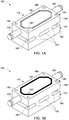
- FIG. 1A is a non-limiting implementation of an embodiment of a heat transfer assembly 100 for transferring heat from an heat emitting device (not shown in FIG.1A , however is shown in FIG 8).
- the heat transfer assembly 100 includes at least one module shown as 110, that has a first part 120 having a recess 130 to receive a portion of the heat emitting device, and a seal component disposed in the recess (shown in FIG. IB), and a second part 140 having a shaped cutout portion 150 and a solid portion 160.
- the second part 140 allows a uniform compression of the sealing component, thus provides a leak-proof sealing for the seal component disposed between the heat emitting device and the module and thus prevents an occurance of leak that can damage the heat emitting device.
- the module 110 is flexible (to the order of 1 mm) to achieve a convex curvature or a concave curvature for load balance to ensure uniform compression for the leak-proof sealing.
- the seal component referred herein in one example is an o-ring seal, and a gasket in another example, and is shown in FIG. 1B by reference numeral 132.
- the sealing component (o-ring, gasket, etc.) could be a separate component, or it could even be integrated into the module through additive manufacturing methods.
- Other components in FIG. 1B are same as shown and described in reference to FIG. 1A . Further details related to compression of the sealing component are described in more detail in reference to FIG. 2A-2F .
- the first part 110 and the second part 130 are mechanically connected to each other.
- the first part 120 and the second part 140 are fabricated as a single integrated unit.
- the heat transfer assembly 100 shown in FIG.1A further includes a module inlet 170 for receiving a coolant and a module outlet 180 for discharging the heat absorbed coolant.
- the coolant is typically a liquid coolant such as water, de-ionised water, water-glycol, and fluoroketones like Novec 649TM for the phase change applications.
- the module inlet 170 and module outlet 180 are coupled to the portion of recess 130 underlying the heat emitting device such that that the coolant touches the portion of the heat emitting device (also sometimes referred to as a baseplate) directly and therefore achieves efficient and effective cooling for the heat emitting device.
- the coolant in one example is a single phase coolant, which implies that the liquid coolant remains liquid even after absorbing heat from the heat transfer device.
- the coolant is a phase change coolant, which implies that the liquid coolant changes into vapor after absorbing heat from the heat transfer device.
- the heat transfer assembly also includes holes for example 190, 190', 190", 190"' that are seen in the drawing, for receiving respective bolts (not shown) for securing the heat emitting device mechanically with the heat transfer assembly 110. It would be understood by those skilled in the art that the desired portion of the heat emitting device is bolted to the respective module using these bolts, where each bolt passes through the first part 120 and the second part 140.
- FIG. 2A-2F further show free body diagrams to explain the non-uniform compression of the sealing component in some prior art designs, as well as the free body diagrams related to embodiments of this disclosure that provide uniform compression of the sealing components.
- a leak occurs at the center 210 of the module 220 (the point farthest from the bolts) due to a long distance which spans the clamping bolts, the clamping force of bolts is shown by the arrows 230 and 240, and the offset force is shown by 250 and 260.
- the center 210 becomes weak over time and that leads to a leak through the sealing component.
- FIG. 2B shows the modified free body diagram 270 for the different embodiments described herein where the reaction forces 230 and 240 applied by bolts and nuts are offset by introducing a four-point bending shown by offset forces 280 and 290, which provides uniform O-ring compression.
- the module 110 of the heat transfer assembly described in different embodiments is therefore able to flex due to the four-point bending and accommodate a concave curvature, as shown diagram 300 in FIG. 2C or a convex curvature, as shown in diagram 350 in FIG. 2D .
- the free body diagram 360 in FIG. 2E shows one embodiment where a single module that implements the features of FIG. 2B - FIG. 2D .
- FIGs 2C-2D also show is the portion of the heat emitting device indicated by reference numeral 310.
- FIG. 2E shows nuts 194 and bolts 192 that are used to attach the module 110 with a portion of the heat emitting device shown by reference numeral 310.
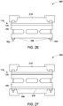
- FIG. 2F shows another embodiment 380 where a double-sided component implements the features of FIG. 2B - FIG. 2D .
- the module includes a third part 320 in addition to the first part 120 and the second part 140, described in reference to FIG. 1 .
- the second part 140 is disposed between the first part 120 and the third part 320, and the third part 320 is a mirror of the first part.
- the heat emitting devices 310 and 390 such as power converters can be positioned on both sides as the first part and the third part, both become accessible for receiving the power converters and the second part provides the required cooling to both the power converters that are positioned on top of the first part and the third part.
- the bolts will pass through the first part, the second part, and the third part and the power converter, or any other heat emitting device.
- first part and second part or first part, second part and third part can be all in one integrated unit as mentioned earlier or in some other embodiments, for example an embodiment 400 as shown in FIG. 3 , these parts, for example the first part and the second part may use a snap fit, using grooves for example to connect to each other, as indicated by reference numeral 410.
- the other components in FIG. 3 are same as in FIG. 1
- FIG. 4 a diagrammatic representation 500 of another embodiment is disclosed where the heat transfer assembly has multiple modules 510, 520, 530 arranged in a linear array, each module having a respective module inlet shown by reference numeral 540, 550, 560 and respective outlet shown by reference numeral 570, 580, and 590 and all the modules connected to a tubing with an assembly inlet 600 and an assembly outlet 610 for providing flow path for the coolant.
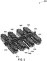
- FIG. 5 is a diagrammatic representation 800 of another embodiment with eight individual modules in one integrated unit, where modules 810, 830 are a mirror of modules 820 and 840 respectively, and modules 850 and 870 are mirror of modules 860 and 880 respectively. Also, the modules 810, 830, 850, 870 are all on one side, whereas the mirror modules 820, 840, 860, and 880 are on the other side separated by a separator 920 A distributed tubing 910 allows the assembly inlet 890 and the assembly outlet 900 to be connected to individual module inlet and module outlet as shown.
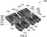
- FIG. 6 is another diagrammatic representation 1000 where the multiple modules 1010, 1030, 1050, 1070 and mirror modules 1020, 1040, 1060, 1080 are arranged such that there is a symmetrical layout to allow a symmetrical flow direction for the coolant in the heat transfer assembly 1000 from the inlet 1090 through the flow channels to enter the respective module inlets of each of the modules, and similarly provides a symmetrical flow path for exit of the coolant through each of the module outlet into the outlet 1300 of the heat transfer assembly 1000.
- a distributed tubing 1310 provides connection of the assembly inlet with each of the module inlet and of each of module outlet with the assembly outlet of the heat transfer assembly.
- the symmetrical flow of the coolant ensures that there is no build up of coolant in any one of the modules with respect to others, and retains a balanced flowpath throughout the heat transfer assembly. As shown, the flow splits in half three times, effectively disrupting the water hammer which is known to cause flow imbalances in prior art designs.
- the symmetrical layout makes the flow path from the inlet to each individual module similar. This makes the flow resistance in each individual module similar, and achieves balanced flow distribution as mentioned herein above.
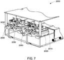
- FIG. 7 a diagrammatic representation 2000 shows a power converter drive with different power converters 2010, 2030, 2050 positioned on top of the respective modules 2020, 2040, and 2060 of the the respective heat transfer assemblies explained in reference to above embodiments, for example embodiments of FIG. 5 and FIG. 6 .
- the individual module or the multiple modules described herein are made from at least one of a polymer material, copolymer material or a composite material, such as polymer-ceramic composite, carbon fibre composite, other non-metals, metals and alloys.
- a polymer material such as polymer-ceramic composite, carbon fibre composite, other non-metals, metals and alloys.
- the entire heat transfer assembly is made from a same material. Further other materials that are compatible with faster manufacturing techniques such as three dimensional printing will also be suitable for the multiple modules described herein.
- the different embodiments of the modules of the heat transfer assembly described herein achieve effective cooling through direct contact of the coolant with the heat emitting device and in addition the modules ensure a leak proof sealing to overcome non-uniform compression of the sealing component, that is critical for heat emitting devices such as power converters and an enabler for direct liquid cooling of heat emitting devices.
- This sealing concept is an enabler for direct liquid cooling, which will reduce the thermal resistance from the power converter device (for example a semiconductor chip) to air by ⁇ 20degC/kW (degree Centigrade/kilo Watt).
- the power converter device will have a greater power rating for the same junction temperature, or alternately a more efficient power conversion (lower junction temperature) for the same power rating.
- a high thermal conductivity material is no longer required in the heat transfer assembly described herein, it can be manufactured from an economical polymer or composite material. Such materials are good insulators, and therefore serve the function of thermal insulation along with providing structural support.
- the insulating structure will also reduce EMI, since the large antenna-like active heatsinks are not required that cause EMI in prior art designs.
- several components in the prior art cooling arrangements such as heatsink, TIM, and accompanying isolating components are made redundant through the different embodiments described herein, enabling a simpler, more compact cooling design with lower labor cost for assembly.
- the embodiments of the heat transfer assembly described herein also achieve a symmetric flow path for the coolant to avoid any pressure build-up due to non-uniform flow build-up in the flow path for the coolant.
- the modular structure of the heat transfer assembly described herein makes it compatible for additive manufacturing.
- the heat transfer assembly is additively manufactured and is injection molded in another implementation, which allow complex, three dimensional geometries for internal flow paths (relative to prior art machined aluminum designs).
- heat transfer assembly has been described herein in relation to cooling of power converter devices as heat emitting devices, however, there the heat emitting devices could be any semiconductor based devices or circuits, these may be a part of computer processing equipment, or electrical motors and generators, or any devices that generate heat during their operation and require cooling for safe operation of their components.
Description
- Embodiments of the present disclosure relate to a heat transfer assembly required for cooling a heat emitting device, such as a power electronic devices or for cooling multiple heat emitting devices.
- Traditionally in liquid cooling of heat emitting devices such as the power electronic devices, the devices are mounted on a cooling plate, referred generally as a cold-plate which is subjected to an internal, single-phase fluid flow of a liquid coolant. Heat generated by the electronic device is conducted through three layers that include, an electronic device baseplate, a Thermal Interface Material (TIM), and the cold-plate body. Finally, the heat is convected into the liquid coolant and transported downstream, to be rejected to ambient.
- There exist different solutions that provide different structures to achieve the cooling described herein above. Some improvements to this cooling also include direct cooling solutions where the TIM layer and the cold-plate body conduction layers are removed and the coolant flow is applied to the baseplate of the power electronic device.
- However, the direct cooling designs often suffer from leak related issues that cause damage to the power electronic device and is a serious reliability concern in the manufacturing of these cooling solutions. Further, some of these designs also suffer from coolant flow distribution issues. Usually, a single pump is used to drive the coolant through multiple flow paths. In several designs, the flow is imbalanced, when one path has a different resistance to coolant flow than the others. Another concern is a water hammer effect in some designs which arises when a high velocity flow bypasses some paths, and creates a much higher flowrate through the final path.
-
US 6 404 628 B1 discloses a heat transfer assembly coupled to a heat emitting device for dissipating heat from the heat emitting device, including a module comprising a body having a first, top part and a second part, the first part having a top surface for mounting heat emitting devices, such as a plurality of IGBT modules mounted to a pin-fin heat sink, thereto and a U-shaped coolant cavity formed adjacent the top of the body, and the second part having a solid portion. A seal component is disposed at the top surface of the first part of the body between the heat emitting devices and the at least one module. The first part and the second part are mechanically connected to each other by being integrally formed as a single unit. A module coolant inlet and a module coolant outlet are fluidly connected to the U-shaped coolant cavity to cause a coolant to flow into the inlet, through the U-shaped coolant cavity and out of the outlet absorbing heat from the heat emitting devices. Portions of the heat emitting devices, like the pin-fin heat sink, may be directly mounted to the first, top part of the module using bolts. -
US 2015/0195951 A1 discloses a cooled electronic assembly having a substrate having a first coefficient of thermal expansion, at least one heat source, in the form of an electronic device or power electronics, operably coupled to the substrate, a carrier plate of a thermally conductive material, operably coupled to the substrate, and a liquid-cooled heat sink. The heat sink, carrier plate, and substrate are configured to direct heat away from the at least one heat source. - Thus, effective sealing and proper flow distribution of the coolant continue to be some challenges in the cooling solutions for heat emitting devices.
- In one aspect, a heat transfer assembly coupled to a heat emitting device for dissipating heat from the heat emitting device is disclosed. The heat transfer assembly includes a module inlet for receiving a coolant; at least one module comprising a first part having a recess to receive a portion of the heat emitting device, and a second part having a shaped cutout portion and a solid portion, wherein the second part allows a uniform compression of a seal component disposed on the first part between the heat emitting device and the at least one module, and wherein the first part and the second part are mechanically connected to each other; and a module outlet for discharging a heat absorbed coolant after absorbing heat from the heat emitting device, where the at least one module is connected to the module inlet and the module outlet. A portion of the heat emitting device is bolted to the at least one module using bolts, where each bolt passes through the first part and the second part. The at least one module is flexible to achieve a convex curvature or a concave curvature for load balance to ensure uniform compression for leak-proof sealing.
- In another embodiment, the heat transfer assembly includes multiple modules arranged in a symmetrical layout to allow a symmetrical flow of the coolant in the heat transfer assembly.
- These and other features, aspects, and advantages of the present invention will become better understood when the following detailed description is read with reference to the accompanying drawings in which like characters represent like parts throughout the drawings, wherein:
-
FIG. 1A is an example implementation of an embodiment of a heat transfer assembly for transferring heat from a heat emitting device; -
FIG. 1B is an example implementation of the embodiment ofFIG. 1A with a sealing component; -
FIG. 2A is a free body diagram to explain non- uniform compression of a sealing component used in prior art; -
FIG. 2B-2F are free body diagrams to show uniform compression in the different implementations of the heat transfer assembly described herein; -
FIG. 3 is a diagrammatic representation of a heat transfer assembly showing a snap fit arrangement between the first and second part of a module of the heat transfer assembly; -
FIG. 4 is a top view of an example implementation of another embodiment of the heat transfer assembly with linearly arranged modules; -
FIG. 5 is a diagrammatic representation of yet another embodiment of the heat transfer assembly with a symmetrical module layout; -
FIG. 6 is a diagrammatic representation of yet another embodiment of the heat transfer assembly showing a symmetrical flow path for a coolant; and -
FIG. 7 is a diagrammatic representation of an embodiment of heat transfer assembly with the heat emitting device. - The different aspects of a heat transfer assembly described herein relate to reliable cooling arrangement for any heat emitting devices that produce heat during their operation. One such device is a power converter device that uses semiconductor based circuitry. Power Converters typically comprise semiconductor switches optionally in combination with other circuitry such as diodes, capacitors, and/or inductors. The heat transfer assembly described herein is particularly beneficial for power converters including silicon carbide switches due to the high heat fluxes associated with such switches. The different aspects described herein focus on geometry of the heat transfer assembly that enables uniform compression of a sealing component that is used to seal the heat emitting device with the heat transfer device and consequently solves any leak related issues that otherwise occur as explained herein above.
- The different embodiments also address other aspects related to heat transfer assembly, such as providing a symmetrical flow path for the coolant, that further enhances the reliable operation of the heat transfer assembly. These embodiments provide simplicity for facile manufacturing without introducing new components, and the materials used for fabrication of the heat transfer assembly provide an electrically insulating structure where the electromagnetic interferences (EMI) in the heat emitting device are also reduced, thereby improving the operation of the heat emitting device as well.
-
FIG. 1A is a non-limiting implementation of an embodiment of aheat transfer assembly 100 for transferring heat from an heat emitting device (not shown inFIG.1A , however is shown in FIG 8). Theheat transfer assembly 100 includes at least one module shown as 110, that has afirst part 120 having arecess 130 to receive a portion of the heat emitting device, and a seal component disposed in the recess (shown in FIG. IB), and asecond part 140 having ashaped cutout portion 150 and asolid portion 160. It would be appreciated by those skilled in the art that thesecond part 140 allows a uniform compression of the sealing component, thus provides a leak-proof sealing for the seal component disposed between the heat emitting device and the module and thus prevents an occurance of leak that can damage the heat emitting device. It may be noted here, that themodule 110 is flexible (to the order of 1 mm) to achieve a convex curvature or a concave curvature for load balance to ensure uniform compression for the leak-proof sealing. The seal component referred herein in one example is an o-ring seal, and a gasket in another example, and is shown inFIG. 1B byreference numeral 132. It may be noted here that the sealing component (o-ring, gasket, etc.) could be a separate component, or it could even be integrated into the module through additive manufacturing methods. Other components inFIG. 1B are same as shown and described in reference toFIG. 1A . Further details related to compression of the sealing component are described in more detail in reference toFIG. 2A-2F . - In different embodiments described herein, the
first part 110 and thesecond part 130 are mechanically connected to each other. In some embodiments, for example the embodiment ofFIG. 1A , thefirst part 120 and thesecond part 140 are fabricated as a single integrated unit. Theheat transfer assembly 100 shown inFIG.1A further includes amodule inlet 170 for receiving a coolant and amodule outlet 180 for discharging the heat absorbed coolant. The coolant is typically a liquid coolant such as water, de-ionised water, water-glycol, and fluoroketones like Novec 649TM for the phase change applications. Themodule inlet 170 andmodule outlet 180 are coupled to the portion ofrecess 130 underlying the heat emitting device such that that the coolant touches the portion of the heat emitting device (also sometimes referred to as a baseplate) directly and therefore achieves efficient and effective cooling for the heat emitting device. - Further, the coolant in one example is a single phase coolant, which implies that the liquid coolant remains liquid even after absorbing heat from the heat transfer device. In another example, the coolant is a phase change coolant, which implies that the liquid coolant changes into vapor after absorbing heat from the heat transfer device.
- The heat transfer assembly also includes holes for example 190, 190', 190", 190"' that are seen in the drawing, for receiving respective bolts (not shown) for securing the heat emitting device mechanically with the
heat transfer assembly 110. It would be understood by those skilled in the art that the desired portion of the heat emitting device is bolted to the respective module using these bolts, where each bolt passes through thefirst part 120 and thesecond part 140. -
FIG. 2A-2F further show free body diagrams to explain the non-uniform compression of the sealing component in some prior art designs, as well as the free body diagrams related to embodiments of this disclosure that provide uniform compression of the sealing components. As is seen in the free body diagram 200 of prior art designs, shown inFIG. 2A , a leak occurs at thecenter 210 of the module 220 (the point farthest from the bolts) due to a long distance which spans the clamping bolts, the clamping force of bolts is shown by thearrows center 210 becomes weak over time and that leads to a leak through the sealing component. -
FIG. 2B shows the modified free body diagram 270 for the different embodiments described herein where the reaction forces 230 and 240 applied by bolts and nuts are offset by introducing a four-point bending shown by offsetforces module 110 of the heat transfer assembly described in different embodiments is therefore able to flex due to the four-point bending and accommodate a concave curvature, as shown diagram 300 inFIG. 2C or a convex curvature, as shown in diagram 350 inFIG. 2D . The free body diagram 360 inFIG. 2E shows one embodiment where a single module that implements the features ofFIG. 2B - FIG. 2D .FIGs 2C-2D also show is the portion of the heat emitting device indicated byreference numeral 310.FIG. 2E showsnuts 194 andbolts 192 that are used to attach themodule 110 with a portion of the heat emitting device shown byreference numeral 310. -
FIG. 2F shows anotherembodiment 380 where a double-sided component implements the features ofFIG. 2B - FIG. 2D . It would be appreciated by those skilled in the art, that in this embodiment the module includes athird part 320 in addition to thefirst part 120 and thesecond part 140, described in reference toFIG. 1 . Thesecond part 140 is disposed between thefirst part 120 and thethird part 320, and thethird part 320 is a mirror of the first part. 120 In this particular embodiment, theheat emitting devices - It would be appreciated by those skilled in the art that the first part and second part or first part, second part and third part can be all in one integrated unit as mentioned earlier or in some other embodiments, for example an
embodiment 400 as shown inFIG. 3 , these parts, for example the first part and the second part may use a snap fit, using grooves for example to connect to each other, as indicated byreference numeral 410. The other components inFIG. 3 are same as inFIG. 1 - Now turning to
FIG. 4 , adiagrammatic representation 500 of another embodiment is disclosed where the heat transfer assembly hasmultiple modules reference numeral reference numeral assembly inlet 600 and anassembly outlet 610 for providing flow path for the coolant. -
FIG. 5 is adiagrammatic representation 800 of another embodiment with eight individual modules in one integrated unit, wheremodules modules modules modules modules mirror modules tubing 910 allows theassembly inlet 890 and theassembly outlet 900 to be connected to individual module inlet and module outlet as shown. -
FIG. 6 is anotherdiagrammatic representation 1000 where themultiple modules mirror modules heat transfer assembly 1000 from theinlet 1090 through the flow channels to enter the respective module inlets of each of the modules, and similarly provides a symmetrical flow path for exit of the coolant through each of the module outlet into theoutlet 1300 of theheat transfer assembly 1000. A distributedtubing 1310 provides connection of the assembly inlet with each of the module inlet and of each of module outlet with the assembly outlet of the heat transfer assembly. - The symmetrical flow of the coolant ensures that there is no build up of coolant in any one of the modules with respect to others, and retains a balanced flowpath throughout the heat transfer assembly. As shown, the flow splits in half three times, effectively disrupting the water hammer which is known to cause flow imbalances in prior art designs. The first time the flow splits as indicated by
arrows arrows arrows arrows FIG. 6 , the symmetrical layout makes the flow path from the inlet to each individual module similar. This makes the flow resistance in each individual module similar, and achieves balanced flow distribution as mentioned herein above. - Turning now to
FIG. 7 , adiagrammatic representation 2000 shows a power converter drive withdifferent power converters respective modules FIG. 5 andFIG. 6 . - The individual module or the multiple modules described herein are made from at least one of a polymer material, copolymer material or a composite material, such as polymer-ceramic composite, carbon fibre composite, other non-metals, metals and alloys. In some embodiments the entire heat transfer assembly is made from a same material. Further other materials that are compatible with faster manufacturing techniques such as three dimensional printing will also be suitable for the multiple modules described herein.
- Thus, the different embodiments of the modules of the heat transfer assembly described herein achieve effective cooling through direct contact of the coolant with the heat emitting device and in addition the modules ensure a leak proof sealing to overcome non-uniform compression of the sealing component, that is critical for heat emitting devices such as power converters and an enabler for direct liquid cooling of heat emitting devices.
- This sealing concept is an enabler for direct liquid cooling, which will reduce the thermal resistance from the power converter device (for example a semiconductor chip) to air by ∼20degC/kW (degree Centigrade/kilo Watt). This implies, that the power converter device will have a greater power rating for the same junction temperature, or alternately a more efficient power conversion (lower junction temperature) for the same power rating. Further, since a high thermal conductivity material is no longer required in the heat transfer assembly described herein, it can be manufactured from an economical polymer or composite material. Such materials are good insulators, and therefore serve the function of thermal insulation along with providing structural support. The insulating structure will also reduce EMI, since the large antenna-like active heatsinks are not required that cause EMI in prior art designs. Thus, several components in the prior art cooling arrangements, such as heatsink, TIM, and accompanying isolating components are made redundant through the different embodiments described herein, enabling a simpler, more compact cooling design with lower labor cost for assembly.
- The embodiments of the heat transfer assembly described herein also achieve a symmetric flow path for the coolant to avoid any pressure build-up due to non-uniform flow build-up in the flow path for the coolant.
- It would be appreciated by those skilled in the art that the modular structure of the heat transfer assembly described herein makes it compatible for additive manufacturing. In one implementation, the heat transfer assembly is additively manufactured and is injection molded in another implementation, which allow complex, three dimensional geometries for internal flow paths (relative to prior art machined aluminum designs).
- It would be appreciated by those skilled in the art, that though the heat transfer assembly has been described herein in relation to cooling of power converter devices as heat emitting devices, however, there the heat emitting devices could be any semiconductor based devices or circuits, these may be a part of computer processing equipment, or electrical motors and generators, or any devices that generate heat during their operation and require cooling for safe operation of their components.
- It would be further understood that not necessarily all such objects or advantages described above may be achieved in accordance with any particular embodiment.
- Thus, for example, those skilled in the art will recognise that the systems and techniques described herein may be embodied or carried out in a manner that achieves or improves one advantage or group of advantages as taught herein without necessarily achieving other objects or advantages as may be taught or suggested herein.
- While the technology has been described in detail in connection with only a limited number of embodiments, it should be readily understood that the specification is not limited to such disclosed embodiments. Rather, the technology can be modified to incorporate any number of variations, alterations, substitutions or equivalent arrangements not heretofore described, but which are within the scope defined by the appended set of claims.
- Additionally, while various embodiments of the technology have been described, it is to be understood that aspects of the specification may include only some of the described embodiments. Accordingly, the specification is not to be seen as limited by the foregoing description, but is only limited by the scope of the appended claims.
Claims (12)
- A heat transfer assembly (100) coupled to a heat emitting device (310, 390) for dissipating heat from the heat emitting device (310,390) the heat transfer assembly (100) comprising:a module inlet (170,540,550,560) for receiving a coolant;at least one module (110) comprising a first part (120) having a recess (130) to receive a portion of the heat emitting device (310,390), and a second part (140) having a shaped cutout portion (150) and a solid portion (160);a sealing component (132) disposed between the heat emitting device (310,390) and the at least one module (110);a module outlet (180) for discharging a heat absorbed coolant after absorbing heat from the heat emitting device (310,390), wherein the at least one module (110) is connected to the module inlet (170,540,550,560) and the module outlet (180),wherein the second part (140) allows a uniform compression of the seal component (132), and wherein the first part (120) and the second part (140) are mechanically connected to each other,wherein a portion of the heat emitting device (310, 390) is bolted to the at least one module (110) using bolts (190, 190', 190", 190"'), where each bolt (190, 190', 190", 190"') passes through the first part (120) and the second part (140), andwherein the at least one module (110) is flexible to achieve a convex curvature or a concave curvature for load balance to ensure uniform compression for leak-proof sealing.
- The heat transfer assembly (100) of claim 1 wherein the coolant is at least one of a single phase coolant or a phase change coolant.
- The heat transfer assembly (100) of claim 1 or 2 wherein the shaped cutout portion (150) and the solid portion (160) in the second part (140) enable a four-point bending for uniform compression of the sealing component (132) .
- The heat transfer assembly (100) of any preceding claim comprising a plurality of modules (1010, 1030, 1050, 1070, 1020, 1040, 1060, 1080) arranged in a symmetrical layout to allow a symmetrical flow of the coolant in the heat transfer assembly (100).
- The heat transfer assembly (100) of claim 4 further comprising an assembly inlet (600,890) for receiving the coolant, wherein the symmetrical layout provides flow direction for the coolant to enter each of the plurality of modules; and an assembly outlet (610, 900) for discharging the heat absorbed coolant received from the plurality of modules (1010, 1030, 1050, 1070, 1020, 1040, 1060, 1080), wherein the assembly inlet (600,890) and the assembly outlet (610, 900) are connected to the module inlet (170,540,550,560) and the module outlet (180) of each module of the plurality of the modules (1010, 1030, 1050, 1070, 1020, 1040, 1060, 1080) through a distributed tubing (910).
- The heat transfer assembly (100) of any preceding claim wherein the first part (120) and the second part (140) are integrated as a single unit.
- The heat transfer assembly (100) of any preceding claim, wherein the first part (120) and the second part (140) use a snap fit configuration to mechanically connect with each other.
- The heat transfer assembly (100) of any preceding claim wherein the at least one module (110) is made from at least one of a polymer material or a composite material.
- The heat transfer assembly (100) of any preceding claim further comprising a third part (320), wherein the second part (140) is disposed between the first part (120) and the third part (320), and wherein the third part (320)is a mirror of the first part (120).
- The heat transfer assembly (100) of claim 9 wherein the portion of the heat emitting device (310,390) is bolted to the at least one module (110), wherein each bolt passes through the first part (120), the second part (140), and the third part (320).
- The heat transfer assembly (100) of any preceding claim wherein the heat emitting device (310,390) is a power converter (2010, 2030, 2050).
- The heat transfer assembly (100) of claim 11 wherein the power converter (2010, 2030, 2050) comprises silicon carbide switches.
Applications Claiming Priority (1)
| Application Number | Priority Date | Filing Date | Title |
|---|---|---|---|
| US15/627,477 US10249554B2 (en) | 2017-06-20 | 2017-06-20 | Heat transfer assembly for a heat emitting device |
Publications (2)
| Publication Number | Publication Date |
|---|---|
| EP3432696A1 EP3432696A1 (en) | 2019-01-23 |
| EP3432696B1 true EP3432696B1 (en) | 2021-04-14 |
Family
ID=62620685
Family Applications (1)
| Application Number | Title | Priority Date | Filing Date |
|---|---|---|---|
| EP18176970.4A Active EP3432696B1 (en) | 2017-06-20 | 2018-06-11 | Heat transfer assembly for a heat emitting device |
Country Status (3)
| Country | Link |
|---|---|
| US (1) | US10249554B2 (en) |
| EP (1) | EP3432696B1 (en) |
| CN (1) | CN109103155B (en) |
Families Citing this family (2)
| Publication number | Priority date | Publication date | Assignee | Title |
|---|---|---|---|---|
| GB2569306A (en) * | 2017-12-12 | 2019-06-19 | Rolls Royce Plc | Thermal management device |
| CN113163696A (en) * | 2021-05-13 | 2021-07-23 | 黑龙江祥辉通信工程有限公司 | Automatic heat dissipation communication device based on 5G |
Family Cites Families (22)
| Publication number | Priority date | Publication date | Assignee | Title |
|---|---|---|---|---|
| US6892796B1 (en) | 2000-02-23 | 2005-05-17 | General Motors Corporation | Apparatus and method for mounting a power module |
| US6404628B1 (en) | 2000-07-21 | 2002-06-11 | General Motors Corporation | Integrated power electronics cooling housing |
| DK174881B1 (en) | 2002-05-08 | 2004-01-19 | Danfoss Silicon Power Gmbh | Multiple cooling cell device for cooling semiconductors |
| US6778393B2 (en) * | 2002-12-02 | 2004-08-17 | International Business Machines Corporation | Cooling device with multiple compliant elements |
| DK176137B1 (en) | 2003-10-27 | 2006-09-25 | Danfoss Silicon Power Gmbh | Flow distribution unit and cooling unit with bypass flow |
| JP4046703B2 (en) * | 2004-03-04 | 2008-02-13 | 三菱電機株式会社 | heatsink |
| US7301770B2 (en) | 2004-12-10 | 2007-11-27 | International Business Machines Corporation | Cooling apparatus, cooled electronic module, and methods of fabrication thereof employing thermally conductive, wire-bonded pin fins |
| ATE513456T1 (en) | 2006-08-10 | 2011-07-15 | Continental Automotive Gmbh | ELECTRONIC UNIT WITH SEALED COOLANT PASSAGE |
| US7796388B2 (en) | 2008-03-17 | 2010-09-14 | Ut-Battelle, Llc | Direct cooled power electronics substrate |
| EP2272311B1 (en) | 2008-05-02 | 2016-10-26 | Danfoss Silicon Power GmbH | Cooling device for a plurality of power modules |
| US20100175857A1 (en) | 2009-01-15 | 2010-07-15 | General Electric Company | Millichannel heat sink, and stack and apparatus using the same |
| US8383260B2 (en) * | 2010-02-26 | 2013-02-26 | GM Global Technology Operations LLC | U-formed cooling plate with solid fins for lithium pouch cells |
| JP2014056982A (en) * | 2012-09-13 | 2014-03-27 | Mitsubishi Electric Corp | Power semiconductor device and manufacturing method of the same |
| GB201303643D0 (en) * | 2013-03-01 | 2013-04-17 | Iceotope Ltd | Cooling system with redundancy |
| US20140352937A1 (en) * | 2013-06-03 | 2014-12-04 | Nathanael Draht | Injection plate for microstructure water cooling units for an electrical or electronic component |
| US20150195951A1 (en) | 2014-01-06 | 2015-07-09 | Ge Aviation Systems Llc | Cooled electronic assembly and cooling device |
| WO2015198411A1 (en) * | 2014-06-25 | 2015-12-30 | 株式会社日立製作所 | Power-module device, power conversion device, and method for manufacturing power-module device |
| US9865522B2 (en) * | 2014-11-18 | 2018-01-09 | International Business Machines Corporation | Composite heat sink structures |
| US9345169B1 (en) * | 2014-11-18 | 2016-05-17 | International Business Machines Corporation | Liquid-cooled heat sink assemblies |
| US9559038B2 (en) * | 2015-04-30 | 2017-01-31 | Deere & Company | Package for a semiconductor device |
| CN108029219B (en) | 2015-05-15 | 2020-04-24 | 维兰德微酷有限责任公司 | Liquid cooled cold plate and method of making same |
| US9941234B2 (en) | 2015-05-28 | 2018-04-10 | Ut-Battelle, Llc | Integrated packaging of multiple double sided cooling planar bond power modules |
-
2017
- 2017-06-20 US US15/627,477 patent/US10249554B2/en active Active
-
2018
- 2018-06-11 EP EP18176970.4A patent/EP3432696B1/en active Active
- 2018-06-20 CN CN201810636246.6A patent/CN109103155B/en active Active
Non-Patent Citations (1)
| Title |
|---|
| None * |
Also Published As
| Publication number | Publication date |
|---|---|
| CN109103155B (en) | 2023-06-16 |
| US20180366391A1 (en) | 2018-12-20 |
| CN109103155A (en) | 2018-12-28 |
| EP3432696A1 (en) | 2019-01-23 |
| US10249554B2 (en) | 2019-04-02 |
Similar Documents
| Publication | Publication Date | Title |
|---|---|---|
| JP7300992B2 (en) | Semiconductor cooling placement device | |
| US8482919B2 (en) | Power electronics card assemblies, power electronics modules, and power electronics devices | |
| US7564129B2 (en) | Power semiconductor module, and power semiconductor device having the module mounted therein | |
| US8232637B2 (en) | Insulated metal substrates incorporating advanced cooling | |
| EP1781076B1 (en) | Electronic assembly having multiple side cooling and method | |
| CN112930078B (en) | Cold plate assembly for electronic components | |
| JP2018512742A (en) | Power electronics module | |
| RU2580374C2 (en) | Heat sinks with c-shaped collectors and milli-channel cooling | |
| CN109390300B (en) | Semiconductor device with a plurality of semiconductor chips | |
| US20100302734A1 (en) | Heatsink and method of fabricating same | |
| EP3236725B1 (en) | Power electronics module | |
| WO2015198411A1 (en) | Power-module device, power conversion device, and method for manufacturing power-module device | |
| WO2015086184A1 (en) | Semiconductor stack arrangement and semiconductor module | |
| EP3432696B1 (en) | Heat transfer assembly for a heat emitting device | |
| US10822096B2 (en) | Avionics cooling module | |
| CN116544198A (en) | Power device assembly and manufacturing method thereof | |
| US20170084515A1 (en) | Power-Module Device and Power Conversion Device | |
| CN111373850B (en) | Power module | |
| CN215528883U (en) | Heat sink, power module package, and inverter | |
| GB2565071A (en) | Semiconductor module | |
| US11856689B2 (en) | Power electronics assemblies and methods of fabricating the same | |
| EP3833171B1 (en) | Cooling system for power modules | |
| US20240057303A1 (en) | Semiconductor cooling arrangement with improved heatsink | |
| EP3245671A1 (en) | A semiconductor module | |
| Earley et al. | Lightweight, Cost-Effective Power Modules Using Polymer Baseplates With Integrated Microconvective Cooling |
Legal Events
| Date | Code | Title | Description |
|---|---|---|---|
| PUAI | Public reference made under article 153(3) epc to a published international application that has entered the european phase |
Free format text: ORIGINAL CODE: 0009012 |
|
| STAA | Information on the status of an ep patent application or granted ep patent |
Free format text: STATUS: THE APPLICATION HAS BEEN PUBLISHED |
|
| AK | Designated contracting states |
Kind code of ref document: A1 Designated state(s): AL AT BE BG CH CY CZ DE DK EE ES FI FR GB GR HR HU IE IS IT LI LT LU LV MC MK MT NL NO PL PT RO RS SE SI SK SM TR |
|
| AX | Request for extension of the european patent |
Extension state: BA ME |
|
| STAA | Information on the status of an ep patent application or granted ep patent |
Free format text: STATUS: REQUEST FOR EXAMINATION WAS MADE |
|
| 17P | Request for examination filed |
Effective date: 20190718 |
|
| RBV | Designated contracting states (corrected) |
Designated state(s): AL AT BE BG CH CY CZ DE DK EE ES FI FR GB GR HR HU IE IS IT LI LT LU LV MC MK MT NL NO PL PT RO RS SE SI SK SM TR |
|
| GRAP | Despatch of communication of intention to grant a patent |
Free format text: ORIGINAL CODE: EPIDOSNIGR1 |
|
| STAA | Information on the status of an ep patent application or granted ep patent |
Free format text: STATUS: GRANT OF PATENT IS INTENDED |
|
| INTG | Intention to grant announced |
Effective date: 20201214 |
|
| GRAS | Grant fee paid |
Free format text: ORIGINAL CODE: EPIDOSNIGR3 |
|
| GRAA | (expected) grant |
Free format text: ORIGINAL CODE: 0009210 |
|
| STAA | Information on the status of an ep patent application or granted ep patent |
Free format text: STATUS: THE PATENT HAS BEEN GRANTED |
|
| AK | Designated contracting states |
Kind code of ref document: B1 Designated state(s): AL AT BE BG CH CY CZ DE DK EE ES FI FR GB GR HR HU IE IS IT LI LT LU LV MC MK MT NL NO PL PT RO RS SE SI SK SM TR |
|
| REG | Reference to a national code |
Ref country code: GB Ref legal event code: FG4D |
|
| REG | Reference to a national code |
Ref country code: CH Ref legal event code: EP |
|
| REG | Reference to a national code |
Ref country code: DE Ref legal event code: R096 Ref document number: 602018015415 Country of ref document: DE |
|
| REG | Reference to a national code |
Ref country code: IE Ref legal event code: FG4D |
|
| REG | Reference to a national code |
Ref country code: AT Ref legal event code: REF Ref document number: 1383638 Country of ref document: AT Kind code of ref document: T Effective date: 20210515 |
|
| REG | Reference to a national code |
Ref country code: LT Ref legal event code: MG9D |
|
| REG | Reference to a national code |
Ref country code: AT Ref legal event code: MK05 Ref document number: 1383638 Country of ref document: AT Kind code of ref document: T Effective date: 20210414 |
|
| REG | Reference to a national code |
Ref country code: NL Ref legal event code: MP Effective date: 20210414 |
|
| PG25 | Lapsed in a contracting state [announced via postgrant information from national office to epo] |
Ref country code: NL Free format text: LAPSE BECAUSE OF FAILURE TO SUBMIT A TRANSLATION OF THE DESCRIPTION OR TO PAY THE FEE WITHIN THE PRESCRIBED TIME-LIMIT Effective date: 20210414 Ref country code: BG Free format text: LAPSE BECAUSE OF FAILURE TO SUBMIT A TRANSLATION OF THE DESCRIPTION OR TO PAY THE FEE WITHIN THE PRESCRIBED TIME-LIMIT Effective date: 20210714 Ref country code: AT Free format text: LAPSE BECAUSE OF FAILURE TO SUBMIT A TRANSLATION OF THE DESCRIPTION OR TO PAY THE FEE WITHIN THE PRESCRIBED TIME-LIMIT Effective date: 20210414 Ref country code: HR Free format text: LAPSE BECAUSE OF FAILURE TO SUBMIT A TRANSLATION OF THE DESCRIPTION OR TO PAY THE FEE WITHIN THE PRESCRIBED TIME-LIMIT Effective date: 20210414 Ref country code: LT Free format text: LAPSE BECAUSE OF FAILURE TO SUBMIT A TRANSLATION OF THE DESCRIPTION OR TO PAY THE FEE WITHIN THE PRESCRIBED TIME-LIMIT Effective date: 20210414 Ref country code: FI Free format text: LAPSE BECAUSE OF FAILURE TO SUBMIT A TRANSLATION OF THE DESCRIPTION OR TO PAY THE FEE WITHIN THE PRESCRIBED TIME-LIMIT Effective date: 20210414 |
|
| PG25 | Lapsed in a contracting state [announced via postgrant information from national office to epo] |
Ref country code: GR Free format text: LAPSE BECAUSE OF FAILURE TO SUBMIT A TRANSLATION OF THE DESCRIPTION OR TO PAY THE FEE WITHIN THE PRESCRIBED TIME-LIMIT Effective date: 20210715 Ref country code: IS Free format text: LAPSE BECAUSE OF FAILURE TO SUBMIT A TRANSLATION OF THE DESCRIPTION OR TO PAY THE FEE WITHIN THE PRESCRIBED TIME-LIMIT Effective date: 20210814 Ref country code: LV Free format text: LAPSE BECAUSE OF FAILURE TO SUBMIT A TRANSLATION OF THE DESCRIPTION OR TO PAY THE FEE WITHIN THE PRESCRIBED TIME-LIMIT Effective date: 20210414 Ref country code: PL Free format text: LAPSE BECAUSE OF FAILURE TO SUBMIT A TRANSLATION OF THE DESCRIPTION OR TO PAY THE FEE WITHIN THE PRESCRIBED TIME-LIMIT Effective date: 20210414 Ref country code: NO Free format text: LAPSE BECAUSE OF FAILURE TO SUBMIT A TRANSLATION OF THE DESCRIPTION OR TO PAY THE FEE WITHIN THE PRESCRIBED TIME-LIMIT Effective date: 20210714 Ref country code: PT Free format text: LAPSE BECAUSE OF FAILURE TO SUBMIT A TRANSLATION OF THE DESCRIPTION OR TO PAY THE FEE WITHIN THE PRESCRIBED TIME-LIMIT Effective date: 20210816 Ref country code: SE Free format text: LAPSE BECAUSE OF FAILURE TO SUBMIT A TRANSLATION OF THE DESCRIPTION OR TO PAY THE FEE WITHIN THE PRESCRIBED TIME-LIMIT Effective date: 20210414 Ref country code: RS Free format text: LAPSE BECAUSE OF FAILURE TO SUBMIT A TRANSLATION OF THE DESCRIPTION OR TO PAY THE FEE WITHIN THE PRESCRIBED TIME-LIMIT Effective date: 20210414 |
|
| REG | Reference to a national code |
Ref country code: DE Ref legal event code: R097 Ref document number: 602018015415 Country of ref document: DE |
|
| PG25 | Lapsed in a contracting state [announced via postgrant information from national office to epo] |
Ref country code: SM Free format text: LAPSE BECAUSE OF FAILURE TO SUBMIT A TRANSLATION OF THE DESCRIPTION OR TO PAY THE FEE WITHIN THE PRESCRIBED TIME-LIMIT Effective date: 20210414 Ref country code: SK Free format text: LAPSE BECAUSE OF FAILURE TO SUBMIT A TRANSLATION OF THE DESCRIPTION OR TO PAY THE FEE WITHIN THE PRESCRIBED TIME-LIMIT Effective date: 20210414 Ref country code: ES Free format text: LAPSE BECAUSE OF FAILURE TO SUBMIT A TRANSLATION OF THE DESCRIPTION OR TO PAY THE FEE WITHIN THE PRESCRIBED TIME-LIMIT Effective date: 20210414 Ref country code: EE Free format text: LAPSE BECAUSE OF FAILURE TO SUBMIT A TRANSLATION OF THE DESCRIPTION OR TO PAY THE FEE WITHIN THE PRESCRIBED TIME-LIMIT Effective date: 20210414 Ref country code: RO Free format text: LAPSE BECAUSE OF FAILURE TO SUBMIT A TRANSLATION OF THE DESCRIPTION OR TO PAY THE FEE WITHIN THE PRESCRIBED TIME-LIMIT Effective date: 20210414 Ref country code: CZ Free format text: LAPSE BECAUSE OF FAILURE TO SUBMIT A TRANSLATION OF THE DESCRIPTION OR TO PAY THE FEE WITHIN THE PRESCRIBED TIME-LIMIT Effective date: 20210414 Ref country code: DK Free format text: LAPSE BECAUSE OF FAILURE TO SUBMIT A TRANSLATION OF THE DESCRIPTION OR TO PAY THE FEE WITHIN THE PRESCRIBED TIME-LIMIT Effective date: 20210414 Ref country code: MC Free format text: LAPSE BECAUSE OF FAILURE TO SUBMIT A TRANSLATION OF THE DESCRIPTION OR TO PAY THE FEE WITHIN THE PRESCRIBED TIME-LIMIT Effective date: 20210414 |
|
| REG | Reference to a national code |
Ref country code: CH Ref legal event code: PL |
|
| PLBE | No opposition filed within time limit |
Free format text: ORIGINAL CODE: 0009261 |
|
| STAA | Information on the status of an ep patent application or granted ep patent |
Free format text: STATUS: NO OPPOSITION FILED WITHIN TIME LIMIT |
|
| REG | Reference to a national code |
Ref country code: BE Ref legal event code: MM Effective date: 20210630 |
|
| 26N | No opposition filed |
Effective date: 20220117 |
|
| PG25 | Lapsed in a contracting state [announced via postgrant information from national office to epo] |
Ref country code: LU Free format text: LAPSE BECAUSE OF NON-PAYMENT OF DUE FEES Effective date: 20210611 |
|
| PG25 | Lapsed in a contracting state [announced via postgrant information from national office to epo] |
Ref country code: LI Free format text: LAPSE BECAUSE OF NON-PAYMENT OF DUE FEES Effective date: 20210630 Ref country code: IE Free format text: LAPSE BECAUSE OF NON-PAYMENT OF DUE FEES Effective date: 20210611 Ref country code: CH Free format text: LAPSE BECAUSE OF NON-PAYMENT OF DUE FEES Effective date: 20210630 |
|
| PG25 | Lapsed in a contracting state [announced via postgrant information from national office to epo] |
Ref country code: IS Free format text: LAPSE BECAUSE OF FAILURE TO SUBMIT A TRANSLATION OF THE DESCRIPTION OR TO PAY THE FEE WITHIN THE PRESCRIBED TIME-LIMIT Effective date: 20210814 Ref country code: AL Free format text: LAPSE BECAUSE OF FAILURE TO SUBMIT A TRANSLATION OF THE DESCRIPTION OR TO PAY THE FEE WITHIN THE PRESCRIBED TIME-LIMIT Effective date: 20210414 |
|
| PG25 | Lapsed in a contracting state [announced via postgrant information from national office to epo] |
Ref country code: IT Free format text: LAPSE BECAUSE OF FAILURE TO SUBMIT A TRANSLATION OF THE DESCRIPTION OR TO PAY THE FEE WITHIN THE PRESCRIBED TIME-LIMIT Effective date: 20210414 Ref country code: BE Free format text: LAPSE BECAUSE OF NON-PAYMENT OF DUE FEES Effective date: 20210630 |
|
| PG25 | Lapsed in a contracting state [announced via postgrant information from national office to epo] |
Ref country code: CY Free format text: LAPSE BECAUSE OF FAILURE TO SUBMIT A TRANSLATION OF THE DESCRIPTION OR TO PAY THE FEE WITHIN THE PRESCRIBED TIME-LIMIT Effective date: 20210414 |
|
| PG25 | Lapsed in a contracting state [announced via postgrant information from national office to epo] |
Ref country code: HU Free format text: LAPSE BECAUSE OF FAILURE TO SUBMIT A TRANSLATION OF THE DESCRIPTION OR TO PAY THE FEE WITHIN THE PRESCRIBED TIME-LIMIT; INVALID AB INITIO Effective date: 20180611 |
|
| PGFP | Annual fee paid to national office [announced via postgrant information from national office to epo] |
Ref country code: FR Payment date: 20230523 Year of fee payment: 6 Ref country code: DE Payment date: 20230523 Year of fee payment: 6 |
|
| PGFP | Annual fee paid to national office [announced via postgrant information from national office to epo] |
Ref country code: GB Payment date: 20230523 Year of fee payment: 6 |
|
| REG | Reference to a national code |
Ref country code: GB Ref legal event code: 732E Free format text: REGISTERED BETWEEN 20231207 AND 20231213 |
|
| PG25 | Lapsed in a contracting state [announced via postgrant information from national office to epo] |
Ref country code: MK Free format text: LAPSE BECAUSE OF FAILURE TO SUBMIT A TRANSLATION OF THE DESCRIPTION OR TO PAY THE FEE WITHIN THE PRESCRIBED TIME-LIMIT Effective date: 20210414 |