EP3432632B1 - Système de communication, procédé de commande de système de communication, dispositif station de base, et dispositif terminal sans fil - Google Patents
Système de communication, procédé de commande de système de communication, dispositif station de base, et dispositif terminal sans fil Download PDFInfo
- Publication number
- EP3432632B1 EP3432632B1 EP17766264.0A EP17766264A EP3432632B1 EP 3432632 B1 EP3432632 B1 EP 3432632B1 EP 17766264 A EP17766264 A EP 17766264A EP 3432632 B1 EP3432632 B1 EP 3432632B1
- Authority
- EP
- European Patent Office
- Prior art keywords
- frame
- training
- wireless terminal
- reception quality
- transmission
- Prior art date
- Legal status (The legal status is an assumption and is not a legal conclusion. Google has not performed a legal analysis and makes no representation as to the accuracy of the status listed.)
- Active
Links
- 238000004891 communication Methods 0.000 title claims description 206
- 238000000034 method Methods 0.000 title claims description 56
- 238000012549 training Methods 0.000 claims description 216
- 230000005540 biological transmission Effects 0.000 claims description 194
- 238000005259 measurement Methods 0.000 claims description 52
- 238000010586 diagram Methods 0.000 description 28
- 230000008569 process Effects 0.000 description 22
- 238000000691 measurement method Methods 0.000 description 11
- 230000004044 response Effects 0.000 description 9
- 230000008901 benefit Effects 0.000 description 6
- 239000003999 initiator Substances 0.000 description 6
- NRNCYVBFPDDJNE-UHFFFAOYSA-N pemoline Chemical compound O1C(N)=NC(=O)C1C1=CC=CC=C1 NRNCYVBFPDDJNE-UHFFFAOYSA-N 0.000 description 4
- 101100148262 Schizosaccharomyces pombe (strain 972 / ATCC 24843) rtx2 gene Proteins 0.000 description 3
- 230000008859 change Effects 0.000 description 3
- 230000009467 reduction Effects 0.000 description 3
- 238000005516 engineering process Methods 0.000 description 2
- 230000010354 integration Effects 0.000 description 2
- 238000012986 modification Methods 0.000 description 2
- 230000004048 modification Effects 0.000 description 2
- 101100172132 Mus musculus Eif3a gene Proteins 0.000 description 1
- 238000004458 analytical method Methods 0.000 description 1
- 239000000470 constituent Substances 0.000 description 1
- 230000006870 function Effects 0.000 description 1
- 238000004519 manufacturing process Methods 0.000 description 1
- 238000012545 processing Methods 0.000 description 1
- 238000013442 quality metrics Methods 0.000 description 1
- 239000000523 sample Substances 0.000 description 1
- 239000004065 semiconductor Substances 0.000 description 1
- 238000010408 sweeping Methods 0.000 description 1
- 230000001360 synchronised effect Effects 0.000 description 1
- 238000012360 testing method Methods 0.000 description 1
- 238000013519 translation Methods 0.000 description 1
Images


Classifications
-
- H—ELECTRICITY
- H04—ELECTRIC COMMUNICATION TECHNIQUE
- H04B—TRANSMISSION
- H04B7/00—Radio transmission systems, i.e. using radiation field
- H04B7/02—Diversity systems; Multi-antenna system, i.e. transmission or reception using multiple antennas
- H04B7/04—Diversity systems; Multi-antenna system, i.e. transmission or reception using multiple antennas using two or more spaced independent antennas
- H04B7/06—Diversity systems; Multi-antenna system, i.e. transmission or reception using multiple antennas using two or more spaced independent antennas at the transmitting station
- H04B7/0613—Diversity systems; Multi-antenna system, i.e. transmission or reception using multiple antennas using two or more spaced independent antennas at the transmitting station using simultaneous transmission
- H04B7/0615—Diversity systems; Multi-antenna system, i.e. transmission or reception using multiple antennas using two or more spaced independent antennas at the transmitting station using simultaneous transmission of weighted versions of same signal
- H04B7/0617—Diversity systems; Multi-antenna system, i.e. transmission or reception using multiple antennas using two or more spaced independent antennas at the transmitting station using simultaneous transmission of weighted versions of same signal for beam forming
-
- H—ELECTRICITY
- H04—ELECTRIC COMMUNICATION TECHNIQUE
- H04B—TRANSMISSION
- H04B7/00—Radio transmission systems, i.e. using radiation field
- H04B7/02—Diversity systems; Multi-antenna system, i.e. transmission or reception using multiple antennas
- H04B7/04—Diversity systems; Multi-antenna system, i.e. transmission or reception using multiple antennas using two or more spaced independent antennas
- H04B7/06—Diversity systems; Multi-antenna system, i.e. transmission or reception using multiple antennas using two or more spaced independent antennas at the transmitting station
- H04B7/0613—Diversity systems; Multi-antenna system, i.e. transmission or reception using multiple antennas using two or more spaced independent antennas at the transmitting station using simultaneous transmission
- H04B7/0615—Diversity systems; Multi-antenna system, i.e. transmission or reception using multiple antennas using two or more spaced independent antennas at the transmitting station using simultaneous transmission of weighted versions of same signal
- H04B7/0619—Diversity systems; Multi-antenna system, i.e. transmission or reception using multiple antennas using two or more spaced independent antennas at the transmitting station using simultaneous transmission of weighted versions of same signal using feedback from receiving side
- H04B7/0621—Feedback content
- H04B7/0632—Channel quality parameters, e.g. channel quality indicator [CQI]
-
- H—ELECTRICITY
- H04—ELECTRIC COMMUNICATION TECHNIQUE
- H04B—TRANSMISSION
- H04B7/00—Radio transmission systems, i.e. using radiation field
- H04B7/02—Diversity systems; Multi-antenna system, i.e. transmission or reception using multiple antennas
- H04B7/04—Diversity systems; Multi-antenna system, i.e. transmission or reception using multiple antennas using two or more spaced independent antennas
- H04B7/06—Diversity systems; Multi-antenna system, i.e. transmission or reception using multiple antennas using two or more spaced independent antennas at the transmitting station
- H04B7/0686—Hybrid systems, i.e. switching and simultaneous transmission
- H04B7/0695—Hybrid systems, i.e. switching and simultaneous transmission using beam selection
-
- H—ELECTRICITY
- H04—ELECTRIC COMMUNICATION TECHNIQUE
- H04L—TRANSMISSION OF DIGITAL INFORMATION, e.g. TELEGRAPHIC COMMUNICATION
- H04L1/00—Arrangements for detecting or preventing errors in the information received
- H04L1/12—Arrangements for detecting or preventing errors in the information received by using return channel
- H04L1/16—Arrangements for detecting or preventing errors in the information received by using return channel in which the return channel carries supervisory signals, e.g. repetition request signals
- H04L1/1607—Details of the supervisory signal
- H04L1/1664—Details of the supervisory signal the supervisory signal being transmitted together with payload signals; piggybacking
-
- H—ELECTRICITY
- H04—ELECTRIC COMMUNICATION TECHNIQUE
- H04L—TRANSMISSION OF DIGITAL INFORMATION, e.g. TELEGRAPHIC COMMUNICATION
- H04L1/00—Arrangements for detecting or preventing errors in the information received
- H04L1/24—Testing correct operation
- H04L1/248—Distortion measuring systems
-
- H—ELECTRICITY
- H04—ELECTRIC COMMUNICATION TECHNIQUE
- H04L—TRANSMISSION OF DIGITAL INFORMATION, e.g. TELEGRAPHIC COMMUNICATION
- H04L5/00—Arrangements affording multiple use of the transmission path
- H04L5/003—Arrangements for allocating sub-channels of the transmission path
- H04L5/0053—Allocation of signaling, i.e. of overhead other than pilot signals
-
- H—ELECTRICITY
- H04—ELECTRIC COMMUNICATION TECHNIQUE
- H04W—WIRELESS COMMUNICATION NETWORKS
- H04W16/00—Network planning, e.g. coverage or traffic planning tools; Network deployment, e.g. resource partitioning or cells structures
- H04W16/24—Cell structures
- H04W16/28—Cell structures using beam steering
-
- H—ELECTRICITY
- H04—ELECTRIC COMMUNICATION TECHNIQUE
- H04W—WIRELESS COMMUNICATION NETWORKS
- H04W24/00—Supervisory, monitoring or testing arrangements
- H04W24/10—Scheduling measurement reports ; Arrangements for measurement reports
Definitions
- the present disclosure relates to a communication system that determines a beam pattern used in communication by performing beamforming training, a method of controlling a communication system, a base station apparatus, and a wireless terminal apparatus.
- millimeter wave communication using radio signals in a millimeter wave band has become popular because of its high transmission rate and no requirement for license.
- a millimeter wave band such as a 60 GHz band, or the like
- standards for wireless communication using a millimeter wave band for example, the following are available: WiGig (Wireless Gigabit), Wireless HD (High Definition), ECMA-387, IEEE802.15.3c, and IEEE802.11ad.
- Radio signals in a millimeter wave band have radio wave characteristics that radio waves propagate in a straightforward manner and a large space propagation loss occurs.
- beamforming is performed to control the directivity of the radio signal using a plurality of antennas.
- the beamforming is a technique of controlling a direction and a width of a beam in a directional communication area while following the location of a wireless communication apparatus with which communication is being performed.
- the beamforming technique in a case where a plurality of communication partners (wireless communication apparatuses) exist in a range within which a terminal forms a beam, connections with the plurality of wireless communication apparatuses are established by performing time-division switching of the beam direction.
- NPL 1 IEEE802.11ad standard
- a technique (beamforming protocol) of selecting a beam pattern for use in communication from a plurality of beam patterns is described in NPL 1.
- wireless communication apparatuses communicating with each other change a beam pattern and transmit, using the changed beam pattern, a training frame including information for selecting an optimum beam pattern thereby selecting the beam pattern optimum for communication.
- US 2015/249929 A1 relates to beamforming training in a situation where interference and reduced Signal To Noise (SNR) can obstruct the transmission quality between a plurality of nearby wireless apparatuses.
- the wireless devices can perform beam training in parallel and in a synchronized way to probe various combinations of directivities used by the plurality of wireless apparatuses.
- a beamforming training between two devices is described, in which a first device sends a plurality of beams while the second (receiving) device measures the quality of each beam.
- the second device transmits a plurality of training beams to the first device, each beam carries a frame that contains all transmission quality results that the second device had measured before.
- NPL 1 IEEE 802.11ad-2012 IEEE Standard for Information Technology-Telecommunications and Information Exchange between systems-Local and Metropolitan networks-Specific requirement-Part 11: Wireless LAN Medium Access Control (MAC) and Physical Layer (PHY) Specifications Amendment Enhancements for Very High Throughput in the 60 GHz Band
- the beam selection is performed not by the first wireless communication apparatus but by the second wireless communication apparatus.
- the second wireless communication apparatus selects a beam pattern having highest reception quality from a plurality of received training frames, and notifies the first wireless communication apparatus of an ID of the selected beam pattern. For example, in a communication system in which a plurality of wireless communication apparatuses exist close to the first wireless communication apparatus and thus much interference is likely to occur, it is desirable that an optimum beam pattern is selected and determined by the first wireless communication apparatus taking into account influence of interference. However, there is no way of feeding back reception results, at the second wireless communication apparatus, of all training frames to the first wireless communication apparatus, it is difficult to make the selection and the decision by the first wireless communication apparatus.
- bi-directional sector sweep in both transmission and reception is performed.
- data is transmitted as feedback information from a second wireless communication apparatus to a first wireless communication apparatus, wherein the feedback data includes identifiers of three best data units of data units received from the first wireless communication apparatus, and best and worst quality identifiers, or all identifiers and corresponding quality metrics.
- a training frame includes information for feeding back a reception result, and thus an increase occurs in the total amount of data of a plurality of training frames, which results in a reduction in communication efficiency.
- One non-limiting and exemplary embodiment of the present disclosure provides a communication system, a method of controlling a communication system, a base station apparatus, and a wireless terminal apparatus, allowing it to maintain a communication efficiency without increasing the total amount of data of training frames even in an environment where a plurality of wireless communication networks exist close to each other.
- the present disclosure provides a communication system including one or more wireless terminal apparatuses and a base station apparatus that performs a wireless communication with the one or more wireless terminal apparatuses, wherein in a transmission beamforming training interval in which beamforming training of a transmission beam is performed, the base station apparatus transmits to the wireless terminal apparatus a plurality of first training frames while sequentially switching a plurality of first transmission beam patterns, the one or more wireless terminal apparatuses perform an operation including, receiving the plurality of first training frames using a particular beam pattern, measuring first reception quality of the received plurality of first training frames, and generating a second feedback frame including the measured first reception quality and transmitting the generated second feedback frame to the base station apparatus, the base station apparatus performs an operation including, receiving the second feedback frame, and selecting one beam pattern from the plurality of first transmission beam patterns based on the first reception quality included in the second feedback frame.
- the present disclosure provides a method of controlling a communication system including one or more wireless terminal apparatuses and a base station apparatus that performs a wireless communication with the one or more wireless terminal apparatuses, the method including, in a transmission beamforming training interval in which beamforming training of a transmission beam is performed, the base station apparatus transmitting to the wireless terminal apparatus a plurality of first training frames while sequentially switching a plurality of first transmission beam patterns, the one or more wireless terminal apparatuses performing an operation including, receiving the plurality of first training frames using a particular beam pattern, measuring first reception quality of the received plurality of first training frames, and generating a second feedback frame including the measured first reception quality and transmitting the generated second feedback frame to the base station apparatus, and the base station apparatus performing an operation including, receiving the second feedback frame, and selecting one beam pattern from the plurality of first transmission beam patterns based on the first reception quality included in the second feedback frame.
- the present disclosure provides a base station apparatus that performs a wireless communication with one or more wireless terminal apparatus, including a transmitter, a receiver, and a controller, wherein in a transmission beamforming training interval in which beamforming training of a transmission beam is performed, the transmitter transmits, to the one or more wireless terminal apparatuses, a plurality of first training frames while sequentially switching a plurality of first transmission beam patterns, the receiver receives a second feedback frame including first reception quality of the plurality of first training frames transmitted from the one or more wireless terminal apparatuses, and the controller selects one beam pattern from the plurality of first transmission beam patterns based on the first reception quality included in the second feedback frame.
- the present disclosure provides a wireless terminal apparatus that performs a wireless communication with a base station apparatus, the wireless terminal apparatus including a receiver, a measurement unit, a control frame generator, and transmitter, wherein in a transmission beamforming training interval in which beamforming training of a transmission beam is performed, the receiver receives, using a particular beam pattern, the plurality of first training frames transmitted by the base station apparatus while sequentially switching the plurality of first transmission beam patterns, the measurement unit measures first reception quality of the received plurality of first training frames, the control frame generator generates a second feedback frame including the measured first reception quality, and the transmitter transmits to the base station apparatus the generated second feedback frame.
- the disclosed embodiments make it possible to maintain a high communication efficiency without increasing the total amount of data of training frames even in an environment in which a plurality of wireless communication networks are located close to each other. Additional benefits and advantages of the disclosed embodiments will become apparent from the specification and drawings. The benefits and/or advantages may be individually obtained by the various embodiments and features of the specification and drawings, which need not all be provided in order to obtain one or more of such benefits and/or advantages.
- one base station manages wireless communication with a plurality of wireless terminal apparatuses (STA (Station)).
- STA wireless terminal apparatuses
- the AP in this one wireless communication network performs beamforming training individually for each STA to select an optimum beam pattern from a plurality of beam patterns.
- the AP it becomes possible for the AP to select a beam pattern that provides highest communication quality, and thus it is possible to achieve best communication quality (system throughput) in the wireless communication network.
- the beam indicates a range (communication area) within which a radio signal can be transmitted and received.
- Fig. 1 is a diagram illustrating a specific example in which overlapping of communication service area occurs between a plurality of wireless communication networks.
- a communication system 300 shown in Fig. 1 two wireless communication networks 80A and 80B are located close to each other.
- the communication system 300 is a communication system according to IEEE802.11ad which is a standard for millimeter wave communication.
- the two wireless communication networks 80A and 80B operate according to the same access control method (for example, CSMA/CA (Carrier Sense Multiple Access with Collision Avoidance) method).
- CSMA/CA Carrier Sense Multiple Access with Collision Avoidance
- the wireless communication network 80A shown in Fig. 1 is a network managed by the AP 81A, and the STA 82A is connected to the AP 81A.
- the wireless communication network 80B is a network managed by the AP 81B, and the STA 82B is connected to the AP 81B.
- the AP 81A and the STA 82A perform beamforming training and select a beam pattern that provides highest communication quality.
- the AP 81B and the STA 82B perform beamforming training and select a beam pattern that provides highest communication quality.
- a communication area 83A is an area in which communication is allowed using a beam pattern selected as a result of beamforming training performed between the AP 81A and the STA 82A.
- a communication area 83B is an area in which communication is allowed using a beam pattern selected as a result of beamforming training performed between the AP 81B and the STA 82B.
- the communication area 83A and the communication area 83B partially overlap each other as shown in Fig. 1 .
- interference such as co-channel interference, adjacent channel interference, or the like can occur, which results in a reduction in communication quality (system throughput).
- DFS Dynamic channel change
- the number of available channels is not large, and thus it is difficult to reduce interference by using DFS.
- an STA when beamforming training is performed, an STA notifies an AP of a beam pattern that provides highest communication quality among training frames received as training signals from the AP.
- the AP since it is easy for the AP to get to know which one of a plurality of transmission beam patterns provides highest communication quality, it is difficult to get to know how good the transmission beam pattern is compared with other transmission beam patterns. No way is provided to feed back reception quality of all training frames evaluated by an STA to an AP, and thus it is difficult for the AP to select a beam pattern taking into account an influence (interference) from other wireless communication networks.
- an STA feeds back information in response to transmission sector sweep performed by an AP, and thus the item in the situation described above can be solved.
- information for notifying of the reception quality is incorporated in each training frame transmitted from an STA to an AP, and thus this information causes an increase in the total amount of data associated with the training frame, which results in a reduction in communication efficiency.
- One non-limiting embodiment of the present disclosure provides a communication system, a method of controlling a communication system, a base station apparatus, and a wireless terminal apparatus, that are capable of maintaining a high communication efficiency without increasing the total amount of data associated with the training frame even in an environment in which a plurality of wireless communication networks are located close to each other.
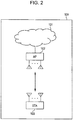
- Fig. 2 is a diagram illustrating an example of a communication system according to an embodiment of the disclosure.
- the communication system 100 shown in Fig. 2 includes a communication network 101 such as the internet, a wireless communication apparatus 102 connected to the communication network 101, and a wireless communication apparatus 103 connected to the communication network 101 via wireless communication performed with the wireless communication apparatus 102.
- the wireless communication apparatus 102 and the wireless communication apparatus 103 have a similar configuration, but they execute different processes depending on whether they operate as an AP (Access Point: base station apparatus) or an STA (Station: wireless terminal apparatus).
- the wireless communication apparatus 102 operates as an access point for the wireless communication apparatus 103 and manages accessing of the wireless communication apparatus 103 to the communication network 101 by performing transferring of data between the wireless communication apparatus 103 and the communication network 101.
- the wireless communication apparatus 102 and the wireless communication apparatus 103 each are a communication apparatus according to the millimeter wave communication standard of IEEE802.11ad.
- Fig. 3 is a diagram illustrating an example of a configuration of the wireless communication apparatus 102 (103).
- the wireless communication apparatus 102 (103) includes a MAC controller 11, a protocol controller 12, a control frame generator 13, a frame generator 14, a transmitter 15, a transmission antenna unit 16, a reception antenna unit 17, a receiver 18, a filter 19, a quality measurer 20, a management table 21, and a beam determiner 22.
- the wireless communication apparatus 102 includes, for example, a CPU (Central Processing Unit) a storage medium such as a ROM (Read Only Memory) or the like in which a control program is stored, and a work memory such as a RAM (Random Access Memory) or the like, and functions of the respective blocks shown in Fig. 3 are realized by the CPU by executing the control program.
- a CPU Central Processing Unit
- ROM Read Only Memory
- RAM Random Access Memory
- the MAC controller 11 controls accessing when data is transmitted or received. More specifically, when a data frame to be transmitted occurs, the MAC controller 11 outputs, to the transmitter 15, a MAC frame including MCS and a beam ID which is index information of a beam pattern to be used in transmission.
- MCS Modulation and Coding Scheme
- a MAC (Media Access Control) frame is a frame including information indicating a transmission destination address and the like.
- the MAC controller 11 When the MAC controller 11 receives a data frame or a training protocol control frame from the filter 19, in a case where the received data is a data frame, the MAC controller 11 outputs data to a higher-level application, but in a case where the received data is a training protocol control frame, the MAC controller 11 outputs a control signal to the protocol controller 12. In a case where the MAC controller 11 acquires a protocol control frame other than the training protocol control frame, the MAC controller 11 performs a protocol control (for example, a connection process, a bandwidth management process, or the like) depending on the acquired protocol control frame.
- the training protocol control frame is a frame including information used in beamforming training described below.
- the protocol controller 12 controls a process associated with the beamforming training. More specifically, based on a training protocol start request acquired from the MAC controller 11, the protocol controller 12 outputs a protocol control frame generation request to the control frame generator 13, and the protocol controller 12 outputs a training frame generation request to the frame generator 14.
- the protocol controller 12 outputs a specification request specifying a reception quality measurement method to the quality measurer 20.
- the reception quality measurement method output here by the protocol controller 12 is specified in specification information included in a first protocol control frame acquired from the MAC controller 11. Details of the specification information will be described later.
- the protocol controller 12 then outputs, to the receiver 18, a reception beam ID for switching a reception beam pattern used in a reception process performed with a wireless communication apparatus with which communication is performed.
- the protocol controller 12 In a case where a training protocol control frame acquired from the wireless communication apparatus with which the communication is performed is received from the MAC controller 11, the protocol controller 12 outputs reception quality information acquired from the quality measurer 20 to the management table 21.
- the control frame generator 13 Based on the protocol control frame generation request acquired from the protocol controller 12, the control frame generator 13 generates a control frame for controlling the training protocol and outputs, to the transmitter 15, the training protocol control frame together with a beam ID specifying a beam pattern for transmitting the training protocol control frame.
- the frame generator 14 generates the training frame based on the training frame generation request acquired from the protocol controller 12, and the frame generator 14 outputs, to the transmitter 15, the generated training frame together with the beam ID specifying the beam pattern for transmitting the training frame.
- the transmitter 15 performs a modulation process, based on the MCS, on the MAC frame, the training protocol control frame, or the training frame respectively acquired from the MAC controller 11, the control frame generator 13, and the frame generator 14, and the transmitter 15 outputs the modulated transmission signal and the beam ID to the transmission antenna unit 16.
- the transmission antenna unit 16 has an array antenna including a plurality of antenna elements and transmits the transmission signal input from the transmitter 15 into space.
- the transmission antenna unit 16 forms a plurality of beam patterns by controlling a phase and/or an amplitude of each antenna element based on information including the beam ID and the line input from the transmitter 15, and the transmission antenna unit 16 transmits the transmission signal using the formed beam patterns.
- the reception antenna unit 17 has an array antenna including a plurality of antenna elements and receives a transmission signal transmitted from another wireless communication apparatus and outputs the received transmission signal as a reception signal to the receiver 18.
- the reception antenna unit 17 forms a plurality of beam patterns by controlling a phase and/or an amplitude of the array antenna and performs reception using the formed beam patterns.
- the receiver 18 demodulates the reception signal acquired from the reception antenna unit 17 and outputs the demodulated data (a reception frame) to the filter 19.
- the receiver 18 controls the array antenna of the reception antenna unit 17 based on the reception beam ID acquired from the protocol controller 12 such that a beam pattern corresponding to the input reception beam ID is formed.
- the filter 19 analyzes a header of the reception frame input from the receiver 18 thereby detecting a frame type of the reception frame. In a case where the filter 19 determines, from a result of the analysis, that the received frame is a training frame, the filter 19 outputs the received frame to the protocol controller 12. In a case where the received frame is a frame other than the training frame, the filter 19 outputs the received frame to the MAC controller 11.
- the quality measurer 20 measures the reception quality of the reception signal based on the measurement method specification request acquired from the protocol controller 12 and the result of the demodulation performed by the receiver 18, and the quality measurer 20 generates reception quality information.
- the quality measurer 20 may employ, as the measurement method, for example, any one of or any combination of RSSI (Received Signal Strength Indicator), SNR (Signal to Noise ratio), SINR (Signal-to-Interference plus Noise power Ratio), an error rate (BER (bit error rate)), PER (packet error rate), FER (frame error rate), and the number of retransmissions.
- the quality measurer 20 outputs the measured reception quality information to the protocol controller 12.
- the management table 21 manages a transmission beam ID corresponding to a beam pattern used in transmitting data to a wireless communication apparatus with which communication is performed and a reception beam ID corresponding to a beam pattern used in receiving data such that the transmission beam ID and the corresponding reception beam ID are associated.
- the management table 21 also manages the beam ID and the corresponding reception quality information received from the quality measurer 20 in an associated manner.
- the beam determiner 22 acquires information regarding a training result from the protocol controller 12, selects a beam pattern to be used in transmission or reception, and notifies the protocol controller 12 of an ID corresponding to the selected beam pattern.
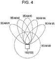
- Fig. 4 is a diagram illustrating an example of a set of beam patterns formed by the wireless communication apparatus 102 (103).
- the wireless communication apparatus 102 forms one of the six types of beam patterns using the array antenna of the transmission antenna unit 16, and perform communication using the formed beam pattern.
- the six types of beam patterns available by the wireless communication apparatus 102 (103) are different in beam direction and include high directivity beam patterns and omnidirectional beam patterns.
- the protocol control is performed mainly using an omnidirectional beam pattern, and the data communication is performed mainly using a high directivity beam pattern.
- the protocol control may be performed using a high directivity beam pattern, and the data communication may be performed using an omnidirectional beam pattern.
- beams #1 to #5 are examples of high directivity beam patterns and beam #0 is an example of an omnidirectional beam pattern.
- beam patterns formed by the transmission antenna unit 16 are described above, beam patterns are formed by the reception antenna unit 17 in a similar manner.
- Fig. 5 is a diagram illustrating a correspondence between a beam pattern and a transmission beam ID and a reception beam ID in each of AP and STA.
- the wireless communication apparatus 102 (103) operates as an AP, it is referred to simply as an AP, while when the wireless communication apparatus 102 (103) operates as an STA, it is referred to simply as an STA.
- a transmission beam ID corresponding to each beam pattern is described in a field of "transmission beam ID" of "AP (Initiator)".
- Each transmission beam ID is represented by #itxN (N is an integer corresponding to the number of beam patterns, and in Fig. 5 , N is one of integers from 1 to 5).
- a reception beam ID #irxN corresponding to each beam pattern is described.
- a transmission beam ID #rtxN corresponding to each beam pattern is described in a field of "transmission beam ID” of "STA (Responder)". Furthermore, in a field of "reception beam ID” of "STA (Responder)", a reception beam ID #rrxN corresponding to each beam pattern is described.
- each beam pattern assigned different beam IDs depending on whether the wireless communication apparatus operates as an AP or an STA and whether the beam pattern is used in transmission or reception.
- the beam IDs it is possible to distinguish, by the beam IDs, between AP and STA and between transmission and reception.
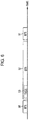
- Fig. 6 is a sequence diagram illustrating an example of a protocol control in the beamforming training in the communication system 100.
- the sequence (scheduling) shown in Fig. 6 is controlled by an AP that manages communication (connections) in the communication system 100.
- the AP is an initiator that transmits a start notification of a beamforming training process
- the STA is a responder that receives the start notification of the beamforming training process.
- the AP periodically provides a BTI (Beacon Transmission Interval) 50 which is an interval in which a beacon is transmitted. More specifically, when a particular time has elapsed since the end of the BTI 50, the AP starts a next BTI 51. Although two BTIs, that is, the BTI 50 and the BTI 51 are shown in Fig. 6 , the BTI is provided repeatedly at particular time intervals until the AP stops the operation.
- BTI Beacon Transmission Interval
- a DTI (Data Transmission Interval) 52 which is an interval in which a data frame is transmitted, is provided between the BTI 50 and the BTI 51.
- DTI 52 data is transmitted and received between the AP and the STA.
- BTI and DTI are defined in IEEE802.11ad.
- the AP provides a TXSS (transmission beamforming training interval) 53 in the DTI 52.
- the TXSS 53 is an interval in which transmission beam training is performed by sweeping beams (that is, by performing transmit sector sweep) for testing communication quality of transmission sectors.
- the operation of the communication system 100 in the TXSS 53 is described in further detail below.
- Fig. 7 is a sequence diagram illustrating an example of an operation of the AP and the STA in the TXSS 53.
- the AP transmits a Grant frame 60, which is a protocol control frame, to the STA.
- Fig. 8 is a diagram illustrating an example of a frame format of the Grant frame 60 which is a protocol control frame.
- the Grant frame 60 includes a frame type 601, a transmission source address 602, a destination address 603, a beam forming protocol ID 604 and specification information 605 indicating a reception quality measurement method.
- the frame type 601 is an identifier or the like indicating that a frame is a protocol control frame.
- the transmission source address 602 is an address (for example, a MAC address or a device ID) of the AP that transmits the Grant frame 60.
- the destination address 603 is an identifier (for example, a MAC address or a device ID) of the STA that receives the Grant frame 60.
- the beam forming protocol ID 604 is an identifier for notifying the STA that the transmission beamforming training according to the present disclosure is to be started.
- the specification information 605 is a field including information specifying that the STA that receives Grant frame 60 to employ a method of measuring reception quality of first to fifth SSW frames 61A to 61E (first training frames) transmitted following the Grant frame 60.
- the measurement method of the reception quality may be, for example, any one of or any combination of RSSI, SNR, SINR, BER, PER, FER, and the number of retransmissions.
- Fig. 7 after the AP transmits the Grant frame 60, the AP transmits the first to fifth SSW frames 61A to 61E.
- Fig. 9 is a diagram illustrating an example of a beam pattern used by each of AP and STA when the first to tenth SSW frames shown in Fig. 7 are transmitted and received.
- Fig. 9 is a diagram illustrating an example of a beam pattern used by each of AP and STA when the first to tenth SSW frames shown in Fig. 7 are transmitted and received.
- SSW frames are sequentially transmitted using transmission beams such that a first SSW frame 61A including a transmission beam ID #itx1 is transmitted using a transmission beam ID #itx1 corresponding to a beam pattern #1, a second SSW frame 61B including a transmission beam ID #itx2 is transmitted using a transmission beam ID #itx2 corresponding to a beam pattern #2, a third SSW frame 61C including a transmission beam ID #itx3 is transmitted using a transmission beam ID #itx3 corresponding to a beam pattern #3, a fourth SSW frame 61D including a transmission beam ID #itx4 is transmitted using a transmission beam ID #itx4 corresponding to a beam pattern #4, and a fifth SSW frame 61E including a transmission beam ID #itx5 is transmitted using a transmission beam ID #itx5 corresponding to a beam pattern #5.
- the first to fifth SSW frames 61A to 61E correspond to the first training frames.
- Fig. 10 is a diagram illustrating an example of a frame format of the SSW frame 61 used as the first training frame.
- the SSW frame 61 includes a frame type 611, a transmission source address 612, a destination address 613, and a transmission beam ID 614.
- the frame type 611 is an identifier indicating that the frame is the first training frame (one of the first to fifth SSW frames 61A to 61 E).
- the transmission source address 612 is an address (for example, a MAC address or a device ID) of an AP that transmits an SSW frame 61.
- the destination address 613 is an identifier (for example, a MAC address or a device ID) of an STA that receives an SSW frame 61.
- the transmission beam ID 614 is a beam ID corresponding to a transmission beam pattern used by an AP that transmits an SSW frame 61. That is, the SSW frame 61 includes a transmission beam ID of a beam pattern used in transmission by an AP (wireless communication apparatus) that transmits the SSW frame 61.
- the STA receives the Grant frame 60 using a reception beam ID #rrx0 corresponding to an omnidirectional beam pattern.
- the STA then receives the first to fifth SSW frames 61A to 61E without changing the beam pattern.
- the STA measures reception quality of each SSW frame using the reception quality measurement method specified by the specification information 605 in the Grant frame 60, and generates a reception quality measurement result Result_STA.
- Fig. 11 is a diagram illustrating examples of reception quality measured by the STA for the first to fifth SSW frames 61A to 61E.
- SNR is used as the reception quality measurement method.
- the SNR is represented in index values converted from dB values.
- the beam ID acquired from the transmission beam ID 614 included in the received first SSW frame 61A is #itx1 and the reception quality measurement result is "80" for the received first SSW frame 61A
- the beam ID acquired from the transmission beam ID 614 included in the received second SSW frame 61B is #itx2 and the reception quality measurement result is "90" for the received second SSW frame 61B
- the beam ID acquired from the transmission beam ID 614 included in the received fourth SSW frame 61D is #itx4 and the reception quality measurement result is "100" for the received fourth SSW frame 61D
- the beam ID acquired from the transmission beam ID 614 included in the received fifth SSW frame 61E is #itx5 and the reception quality measurement result is "70” for the received fifth SSW frame 61E.
- Fig. 11 does not include the beam ID and the reception quality for the third SSW frame 61C. This means that the STA did not receive the third SSW frame 61C. Note that when the AP transmits the first to fifth SSW frames 61A to 61E, the AP changes the beam pattern each time one SSW frame 61 is transmitted. Therefore, there can occur a possibility that the STA does not receive an SSW frame 61, as with the case shown in Fig. 11 in which the third SSW frame 61C is not received.
- the AP After the AP transmits the fifth SSW frame 61E, the AP sets the beam pattern to the reception beam ID #irx0 corresponding to the omnidirectional beam pattern #0 to measure the reception quality of the training frame transmitted by the STA.
- the STA After the STA receives the fifth SSW frame 61E, the STA sequentially transmits a sixth SSW frame 62A including a transmission beam ID #rtx1 using a transmission beam ID #rtx1 corresponding to the beam pattern #1, a seventh SSW frame 62B including a transmission beam ID #rtx2 using a transmission beam ID #rtx2 corresponding to the beam pattern #2, an eighth SSW frame 62C including a transmission beam ID #rtx3 using a transmission beam ID #rtx3 corresponding to the beam pattern #3, a ninth SSW frame 62D including a transmission beam ID #rtx4 using a transmission beam ID #rtxr corresponding to the beam pattern #4, and a tenth SSW frame 62E including a transmission beam ID #rtx5 using a transmission beam ID #rtx5 corresponding to the beam pattern #5, as shown in Fig. 9 .
- the sixth to tenth SSW frames 62A to 62E correspond to the second training frames.
- the frame format of the SSW frame 62 used as the second training frame is similar to the frame format of the SSW frame 61 used as the first training frame shown in Fig. 10 , and thus a further description thereof is omitted.
- one of, or generically all of, the sixth to tenth SSW frames 62A to 62E is also referred to as an SSW frame 62.
- Each SSW frame may include a beam ID selected by a wireless terminal that received the SSW frame and reception quality thereof. More specifically, the STA may transmit information indicating the beam ID that provides the highest reception quality among the received first to fifth SSW frames 61A to 61E and the measured reception quality thereof such that the beam ID and the reception quality are included in the sixth to tenth SSW frames 62A to 62E.
- the AP After the AP transmits the fifth SSW frame 61E, the AP receives the sixth to tenth SSW frames 62A to 62E transmitted from the STA, and measures the reception quality of each SSW frame using the same reception quality measurement method as the reception quality measurement method notified, using the specification information 605 in the Grant frame 60, to the STA, and generates a reception quality measurement result Result_AP.
- Fig. 12 is a diagram illustrating, by way of example, beam IDs and measurement results of reception quality acquired from transmission beam 10s 614 included in the SSW frames when the AP receives the sixth to tenth SSW frames 62A to 62E.
- SNR is used as the reception quality measurement method.
- Fig. 12 shows the beam ID acquired from the transmission beam ID 614 included in the received sixth SSW frame 62A is #rtx1 and the reception quality measurement result is "30" for the received sixth SSW frame 62A
- the beam ID acquired from the transmission beam ID 614 included in the received seventh SSW frame 62B is #rtx2 and the reception quality measurement result is "90" for the received seventh SSW frame 62B
- the beam ID acquired from the transmission beam ID 614 included in the received eighth SSW frame 62C is #rtx3 and the reception quality measurement result is "80" for the received eighth SSW frame 62C
- the beam ID acquired from the transmission beam ID 614 included in the received ninth SSW frame 62D is #rtx4 and the reception quality measurement result is "95” for the received ninth SSW frame 62D
- the beam ID acquired from the transmission beam ID 614 included in the received tenth SSW frame 62E is #rtx5 and the reception quality measurement result is "60" for the received tenth SSW frame
- the AP After the AP receives the tenth SSW frame 62E, the AP generates an SSW-Feedback frame 63 as a first feedback frame including the measurement result Result_AP of the reception quality of the received sixth to tenth SSW frames 62A to 62E, and the AP transmits the generated SSW-Feedback frame 63 using the omnidirectional beam pattern, that is, the beam pattern corresponding to the transmission beam ID #itx0.
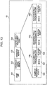
- Fig. 13 is a diagram illustrating an example of a frame format of the SSW-Feedback frame 63 which is the first feedback frame.
- the SSW-Feedback frame 63 includes a frame type 631, a transmission source address 632, a destination address 633, and a measurement result 634.
- the frame type 631 is an identifier or the like indicating that a frame is the SSW-Feedback frame 63.
- the transmission source address 632 is an address (for example, a MAC address or a device ID) of the AP that transmits the SSW-Feedback frame 63.
- the destination address 633 is an identifier (for example, a MAC address or a device ID) of the STA that receives the SSW-Feedback frame 63.
- the measurement result 634 corresponds to the reception quality measurement result Result_AP described above.
- the number of measurement results 635 is a field including information regarding the number of measurement results included in the measurement result 634. More specifically, "5" is stored in the number of measurement results 635 in the SSW-Feedback frame 63 which is the first feedback frame, and "4" is stored in the number of measurement results 635 in the SSW-ACK frame 64 which is the second feedback frame.
- the measurement result #n 636 n includes a beam ID 637 and reception quality 638, that is, the measurement result #n 636 n is a field including information indicating a beam ID and measured reception quality acquired from an SSW frame when the AP receives the sixth to tenth SSW frames 62A to 62E.
- the STA After the STA receives the SSW-Feedback frame 63 transmitted by the AP, the STA acquires the measurement result 634 corresponding to Result_AP from the SSW-Feedback frame 63. The STA selects, based on the acquired Result_AP, a transmission beam pattern satisfying a particular selection criterion, and the STA associates the selected beam pattern with a transmission beam ID #rtx_select used in communication with the AP.
- the STA selects, as a transmission beam pattern for use by the STA, a beam pattern having lowest reception quality of beam patterns satisfying the reception quality that allows it to achieve communication quality (throughput, delay time, and the like) required by an application.
- the STA may select a beam #itx3 with quality of "80" which is the lowest among beams with SNR higher than "70".
- the STA may select a beam #itx5 with quality of "60" which is the lowest among beams with SNR higher than "50”.
- the STA may select, as the transmission beam pattern for use by the STA, a beam ID that provides the highest reception quality. More specifically, the STA selects, as #rtx_select, #rtx4 having reception quality of "95".
- the STA After the STA selects the transmission beam pattern from the acquired Result_AP, the STA generates an SSW-ACK frame 64, as a second feedback frame, including measurement result Result_STA indicating a result of measurement of reception quality of the first to fifth SSW frames 61A to 61E, and the STA transmits, to the AP, the generated SSW-ACK frame 64 using a beam pattern corresponding to a transmission beam ID #rtx0 which is an omnidirectional beam pattern. Note that instead of using the omnidirectional beam pattern in the transmission, the STA may transmit the generated SSW-ACK frame 64 using a beam pattern corresponding to the selected beam ID #rtx_select.
- the frame format of the SSW-ACK frame which is the second feedback frame, is similar to the frame format of the second SSW-Feedback frame described above with reference to Fig. 13 , and thus a further description thereof is omitted.
- the AP receives the SSW-ACK frame 64 transmitted by the STA and acquires the reception quality measurement result Result_STA included in the SSW-ACK frame 64.
- the STA selects, based on the acquired Result_STA, a transmission beam pattern satisfying a particular selection criterion, and the AP associates the selected beam pattern with a transmission beam ID #itx_select used in communication with the STA.
- the particular selection criterion is similar to that for the selection by the STA based on the Result_AP described above, and thus a further description thereof is omitted.
- the protocol control of the beamforming training in the wireless communication apparatus 102 (103) has been described above.
- TXSS 53 which is an interval in which the transmission beam pattern is determined
- the STA measures the reception quality of the SSW frame 61 and transmits, to the AP, the SSW-ACK frame 64 (second feedback frame) including the measurement result Result_STA.
- the AP selects a beam pattern satisfying the particular selection criterion based on Result_STA and employs the selected beam pattern as the transmission beam pattern for use in transmission to the STA.
- the AP receives the sixth to tenth SSW frames 62A to 62E (second training frames) transmitted from the STA, the AP measures the reception quality of the SSW frames 62 and transmits the measurement result by incorporating it in an SSW-Feedback frame 63 (first feedback frame) to the STA.
- the STA selects a beam pattern satisfying the particular selection criterion based on Result_STA and employs the selected beam pattern as a transmission beam pattern for use in transmission to the AP.
- the technique described above makes it possible for the AP to acquire the information regarding the reception quality of the beam received by the STA without resulting in an increase in data size of the training frames.
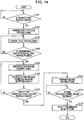
- Fig. 14 is a flow chart illustrating an example of an operation of the AP when the AP operates as an initiator.
- step S101 the protocol controller 12 of the AP determines whether a beamforming training start request is input from the MAC controller 11. In a case where the training start request is input from the MAC controller 11 (YES in S101), the process proceeds to step S102. In a case where the training start request is not input from the MAC controller 11 (NO in S101), step S101 is repeated.
- step S102 the protocol controller 12 outputs, to the control frame generator 13, a protocol control frame generation request for starting the protocol control of the beamforming training, and the transmitter 15 transmits a protocol control frame generated by the control frame generator 13 to the STA.
- the protocol control frame corresponds to the Grant frame 60 shown in Fig. 7
- the protocol control frame includes an identifier (beam forming protocol ID) indicating that the beamforming training according to the present embodiment of the disclosure is to be started and specification information 605 specifying the method of measuring the reception quality of the SSW frame received by the STA.
- step S103 the protocol controller 12 outputs a first training frame generation request to the frame generator 14.
- the frame generator 14 generates a plurality of first training frames
- the transmitter 15 transmits the generated plurality of first training frames to the STA while switching the directional beam pattern each time one frame is transmitted.
- the first training frames correspond to the first to fifth SSW frames 61A to 61E shown in Fig. 7 .
- step S104 the protocol controller 12 determines whether the transmission is completed for all first training frames. In a case where it is determined that the transmission is completed for all first training frames, (YES in S104), the process proceeds to step S105, but otherwise (NO in S104) the process returns to step S103.
- step S105 the protocol controller 12 outputs a reception beam switch instruction to the receiver 18 to switch the beam pattern to an omnidirectional beam pattern (beam ID #irx0) for use in receiving the second training frame transmitted, in response to receiving the first training frame, by the STA.
- the second training frames correspond to the sixth to tenth SSW frames 62A to 62E shown in Fig. 7 .
- step S106 the protocol controller 12 instructs that the plurality of second training frames transmitted from the STA are received by the reception antenna unit 17 using the omnidirectional beam pattern, and instructs that the quality measurer 20 measures the reception quality of each of the received second training frames.
- the protocol controller 12 of the AP can know the timing of the end of the transmission of the second training frames.
- each second training frame includes information indicating the number of frames that have already been transmitted and information indicating the total number of frames to be transmitted
- the protocol controller 12 of the AP can calculate the end of the second training frames from the number of remaining frames to be transmitted because each second training frame has a fixed length and the modulation rate is fixed.
- step S107 the protocol controller 12 of the AP determines whether the transmission of the second training frames from the STA is completed and at least one of the plurality of the second training frames is received. In a case where it is determined that the transmission of the second training frames from the STA is completed, and at least one second training frame is received (YES in S107), the process proceeds to step S108, but otherwise (in a case where any one of the second training frames is not received) (NO in S107), the process returns to step S105.
- step S108 the protocol controller 12 outputs, to the control frame generator 13, a request for generation of a first feedback frame including the reception quality measurement result generated in step S106, and performs control such that the generated first feedback frame is transmitted to the STA.
- the first feedback frame corresponds to the SSW-Feedback frame 63 shown in Fig. 7 .
- step S109 the protocol controller 12 determines whether a second feedback frame is received from the STA.
- the second feedback frame corresponds to the SSW-ACK frame 64 shown in Fig. 7 , and includes the result of the measurement of the reception quality of the first training frames received by the STA.
- the process proceeds to step S110, but otherwise (NO in S109), the process repeats step S109.
- step S110 the protocol controller 12 selects a transmission beam pattern satisfying the particular selection criterion based on the measurement result, included in the second feedback frame received in step S109, as to reception quality of the first training frames received by the STA.
- the transmission beam pattern selected in this step S110 will be used later by the AP in transmission to the STA.
- the protocol controller 12 then stores a beam ID corresponding to the selected transmission beam pattern and the STA which is the destination of the transmission in the management table 21 in an associated manner. Thereafter, the beamforming training process is ended.
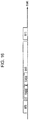
- Fig. 15 is a flow chart illustrating an example of an operation of the STA when the STA operates as a responder.
- step S201 the filter 19 determines whether a protocol control frame transmitted from the AP is received. In a case where a protocol control frame transmitted from the AP is received (YES in S201), the filter 19 outputs the protocol control frame to the MAC controller 11, but otherwise (NO in S201), the filter 19 repeats step S201.
- the protocol control frame corresponds to the Grant frame 60 shown in Fig. 7 , and includes an identifier (beam forming protocol ID) indicating that the beamforming training according to the present embodiment of the disclosure is to be started.
- step S202 the protocol controller 12 outputs a reception beam switch instruction to the receiver 18 to switch the beam pattern to an omnidirectional beam pattern for use in receiving a plurality of first training frames transmitted from the AP following the protocol control frame.
- step S203 the protocol controller 12 instructs that the reception antenna unit 17 receives the plurality of first training frames transmitted from the AP by using the omnidirectional beam pattern and that the quality measurer 20 measures the reception quality of each of the received first training frames.
- the protocol controller 12 of the STA can know the timing of the end of the transmission of the first training frames.
- the protocol controller 12 of the STA can calculate the end of the first training frames from the number of remaining frames to be transmitted because each first training frame has a fixed length and the modulation rate is fixed.
- step S204 the protocol controller 12 of the STA determines whether the transmission of the first training frames from the AP is completed and at least one of the plurality of the first training frames is received. In a case where it is determined that the transmission of the first training frames from the AP is completed, and at least one first training frame is received (YES in S204), the process proceeds to step S206, but otherwise (in a case where any one of the first training frames is not received) (NO in S204), the process returns to step S203.
- step S205 the protocol controller 12 outputs a second training frame generation request to the frame generator 14.
- the frame generator 14 generates a plurality of second training frames
- the transmitter 15 transmits the generated plurality of second training frames to the AP while switching the beam pattern used in the transmission each time one frame is transmitted.
- the second training frames correspond to the sixth to tenth SSW frames 62A to 62E shown in Fig. 7 .
- step S206 the protocol controller 12 determines whether the transmission is completed for all second training frames. In a case where it is determined that the transmission is completed for all second training frames, (YES in S206), the process proceeds to step S207, but otherwise (NO in S206), the process returns to step S205.
- step S207 the protocol controller 12 determines whether a first feedback frame is received from the AP. As described above, the first feedback frame corresponds to the SSW-Feedback frame 63 shown in Fig. 7 . In a case where it is determined that the first feedback frame is received (YES in S207), the process proceeds to step S208, but otherwise (NO in S207), the process repeats step S207.
- step S208 the protocol controller 12 of the STA selects a transmission beam pattern satisfying a particular selection criterion based on the measurement result 634 included in the first feedback frame received in step S207.
- the transmission beam pattern selected in this step S208 will be used later by the STA in transmission to the AP.
- the protocol controller 12 then stores a beam ID corresponding to the selected transmission beam pattern and the AP which is the destination of the transmission in the management table 21 in an associated manner.
- step S209 the protocol controller 12 instructs that a second feedback frame generation request is to be output to the control frame generator 13, and the generated second feedback frame is to be transmitted to the transmitter 15 and is to be further transmitted to the AP from the transmission antenna unit 16.
- the second feedback frame corresponds to the SSW-ACK frame 64, and includes a measurement result 634 of the reception quality of the first training frames received by the STA. After the transmission of the second feedback frame is completed, the protocol controller 12 ends the beamforming training.
- the STA when the STA receives first training frames (the first to fifth SSW frames 61A to 61E) transmitted from the AP, the STA measures the reception quality of the SSW frame 61 and transmits the measurement result Result_STA to the AP by transmitting the second feedback frame (the SSW-ACK frame 64) including the measurement result Result_STA.
- the AP selects a beam pattern satisfying the particular selection criterion based on Result_STA and employs the selected beam pattern as the transmission beam pattern for use in transmission to the STA.
- the AP receives the second training frames (the sixth to tenth SSW frames 62A to 62E) transmitted from the STA, the AP measures the reception quality of the SSW frames 62 and transmits the measurement result to the STA by incorporating the measurement result in the first feedback frame (the SSW-Feedback frame 63).
- the STA selects a beam pattern satisfying the particular selection criterion based on Result_STA and employs the selected beam pattern as a transmission beam pattern for use in transmission to the AP.
- the technique described above makes it possible for the AP to acquire the information regarding the reception quality of the beam received by the STA without resulting in an increase in data size of the training frames.
- the beamforming training is performed using the first training frame and the second training frame.
- the beamforming training may be performed using the Grant frame 60 and the second training frames (the sixth to tenth SSW frames 62A to 62E) transmitted from the STA, and the first feedback frame (SSW-Feedback frame 63) shown in Fig. 7 .
- the beamforming training may be performed using the Grant frame 60, the first training frames (the first to fifth SSW frames 61A to 61E) transmitted from the AP, and the second feedback frame (the SSW-ACK frame 64).
- the communication system 100 includes one AP and one STA.
- the present disclosure is not limited to those embodiments.
- the communication system according to the present disclosure may include a plurality of APs and a plurality of STAs.
- a plurality of TXSSs for the STAs may be sequentially provided depending on the number of STAs.
- Fig. 16 is a sequence diagram illustrating an example of a protocol control in the beamforming training for two STAs.
- Each functional block according to the embodiments described above may be typically realized by an integrated circuit such as an LSI having input and output terminals.
- Each of the functional blocks may be formed individually on one chip, or part or all of the functional blocks may be formed on one chip.
- the LSI may also be referred to as an IC (Integrated Circuit), a system LSO, a super LSI, or an ultra LSI depending on the degree of integration.
- the technique of implementing the integrated circuit is not limited to the LSI, but the integrated circuit may be realized in the form of a dedicated circuit or a general-purpose processor.
- the integrated circuit may also be realized using an FPGA (Field Programmable Gate Array) that can be programmed after the manufacture of the LSI or a reconfigurable processor that is allowed to be reconfigured in terms of the connection or the setting of circuit cells in the inside of the LSI.
- FPGA Field Programmable Gate Array
- the functional blocks may be realized using such a new technique.
- a possible example of a new technique is biotechnology.
- the present disclosure provides a communication system including one or more wireless terminal apparatuses and a base station apparatus that performs a wireless communication with the one or more wireless terminal apparatuses, wherein in a transmission beamforming training interval in which beamforming training of a transmission beam is performed, the base station apparatus transmits to the wireless terminal apparatus a plurality of first training frames while sequentially switching a plurality of first transmission beam patterns, the one or more wireless terminal apparatuses perform an operation including, receiving the plurality of first training frames using a particular beam pattern, measuring first reception quality of the received plurality of first training frames, and generating a second feedback frame including the measured first reception quality and transmitting the generated second feedback frame to the base station apparatus, and the base station apparatus performs an operation including, receiving the second feedback frame, and selecting one beam pattern from the plurality of first transmission beam patterns based on the first reception quality included in the second feedback frame.
- the one or more wireless terminal apparatuses perform an operation including, after receiving the plurality of first training frames using a particular beam pattern, transmitting, to the base station apparatus, a plurality of second training frames while sequentially switching a plurality of second transmission beam patterns
- the base station apparatus performs an operation including, receiving the plurality of second training frames using a particular beam pattern, measuring second reception quality of the received plurality of second training frames, and transmitting, to the one or more wireless terminal apparatuses, a first feedback frame including the measured second reception quality
- the one or more wireless terminal apparatuses perform an operation including, receiving the first feedback frame, and selecting a transmission beam pattern based on the second reception quality included in the received first feedback frame.
- the base station apparatus and the wireless terminal apparatus perform a wireless communication according to IEEE802.11ad.
- the base station apparatus when the transmission beamforming training interval is started, transmits, to the wireless terminal apparatus, a frame including an identifier notifying the wireless terminal apparatus of the start of specific beamforming training.
- each of the first and the second reception quality is any one of or any combination of at least RSSI (Received Signal Strength Indicator), SNR (Signal-to-Noise Ratio), SINR (Signal-to-Interference plus Noise power Ratio), BER (Bit Error Rate), PER (Packet Error Rate), FER (Frame Error Rate), and the number of retransmissions.
- RSSI Receiveived Signal Strength Indicator
- SNR Signal-to-Noise Ratio
- SINR Signal-to-Interference plus Noise power Ratio
- BER Bit Error Rate
- PER Packet Error Rate
- FER Frerame Error Rate
- the base station apparatus after the transmission beamforming training with a first wireless terminal apparatus of the one or more wireless terminal apparatuses is completed, the base station apparatus subsequently performs the transmission beamforming training with a second wireless terminal apparatus of the one or more wireless terminal apparatuses.
- the present disclosure provides a method of controlling a communication system including one or more wireless terminal apparatuses and a base station apparatus that performs a wireless communication with the one or more wireless terminal apparatuses, the method including, in a transmission beamforming training interval in which beamforming training of a transmission beam is performed, the base station apparatus transmitting to the wireless terminal apparatus a plurality of first training frames while sequentially switching a plurality of first transmission beam patterns, the one or more wireless terminal apparatuses performing an operation including, receiving the plurality of first training frames using a particular beam pattern, measuring first reception quality of the received plurality of first training frames, and generating a second feedback frame including the measured first reception quality and transmitting the generated second feedback frame to the base station apparatus, and the base station apparatus performing an operation including, receiving the second feedback frame, and selecting one beam pattern from the plurality of first transmission beam patterns based on the first reception quality included in the second feedback frame.
- the present disclosure provides a base station apparatus that performs a wireless communication with one or more wireless terminal apparatus, including a transmitter, a receiver, and a controller, wherein in a transmission beamforming training interval in which beamforming training of a transmission beam is performed, the transmitter transmits, to the one or more wireless terminal apparatuses, a plurality of first training frames while sequentially switching a plurality of first transmission beam patterns; the receiver receives a second feedback frame including first reception quality of the plurality of first training frames transmitted from the one or more wireless terminal apparatuses, and the controller selects one beam pattern from the plurality of first transmission beam patterns based on the first reception quality included in the second feedback frame.
- a wireless terminal apparatus that performs a wireless communication with a base station apparatus, including a receiver, a measurement unit, a control frame generator, a transmitter, wherein in a transmission beamforming training interval in which beamforming training of a transmission beam is performed, the receiver receives, using a particular beam pattern, the plurality of first training frames transmitted by the base station apparatus while sequentially switching the plurality of first transmission beam patterns, the measurement unit measures first reception quality of the received plurality of first training frames, the control frame generator generates a second feedback frame including the measured first reception quality, and the transmitter transmits to the base station apparatus the generated second feedback frame.
- the present disclosure can be preferably applied to a communication system in which beamforming training is performed.
Landscapes
- Engineering & Computer Science (AREA)
- Signal Processing (AREA)
- Computer Networks & Wireless Communication (AREA)
- Physics & Mathematics (AREA)
- Nonlinear Science (AREA)
- Mobile Radio Communication Systems (AREA)
- Radio Transmission System (AREA)
Claims (8)
- Système de communication (100) comprenant un ou plusieurs dispositifs terminaux sans fil (103) et un dispositif station de base (102) qui est configuré pour exécuter une communication sans fil avec l'un ou plusieurs dispositifs terminaux sans fil (103), dans lequel
dans un intervalle d'entraînement de formation de faisceau de transmission dans lequel un entraînement de formation de faisceau d'un faisceau de transmission est effectué,
le dispositif station de base (102) est configuré pour transmettre au dispositif terminal dans fil (103) une pluralité de premières trames d'entraînement (61A à 61E) tout en commutant séquentiellement une pluralité de premiers schémas de faisceau de transmission,
l'un ou plusieurs dispositifs terminaux sans fil (103) sont configurés pour exécuter un fonctionnement incluant :réception de la pluralité de premières trames d'entraînement (61A à 61E) en utilisant un schéma de faisceau particulier,mesure d'une première qualité de réception de la pluralité reçue de premières trames d'entraînement (61A à 61E), etgénération d'une deuxième trame de retour d'information incluant la première qualité de réception mesurée, et après réception de la pluralité de premières trames d'entraînement (61A à 61E) en utilisant un schéma de faisceau particulier, transmission, au dispositif station de base, d'une pluralité de deuxièmes trames d'entraînement (62A à 62E) tout en commutant séquentiellement une pluralité de deuxièmes schémas de faisceau de transmission,caractérisé en ce quele dispositif station de base (102) est configuré pour exécuter un fonctionnement incluant :réception de la pluralité de deuxièmes trames d'entraînement (62A à 62E) en utilisant un schéma de faisceau particulier,mesure d'une deuxième qualité de réception de la pluralité reçue de deuxièmes trames d'entraînement (62A à 62E), ettransmission, à l'un ou plusieurs dispositifs terminaux sans fil (103), d'une première trame de retour d'information (63) incluant la deuxième qualité de réception mesurée, etl'un ou plusieurs dispositifs terminaux sans fil (103) sont configurés pour exécuter un fonctionnement incluant :réception de la première trame de retour d'information (63),sélection d'un schéma de faisceau de transmission selon la deuxième qualité de réception incluse dans la première trame de retour d'information reçue, etaprès sélection du schéma de faisceau de transmission, transmission de la deuxième trame de retour d'information générée (64) au dispositif station de base, etle dispositif station de base (102) est configuré pour exécuter un fonctionnement incluant :réception de la deuxième trame de retour d'information (64), etsélection d'un schéma de faisceau issu de la pluralité de premiers schémas de faisceau de transmission selon la première qualité de réception incluse dans la deuxième trame de retour d'information (64). - Le système de communication (100) selon la revendication 1, dans lequel le dispositif station de base (102) et le dispositif terminal sans fil (103) sont configurés pour exécuter une communication sans fil selon la norme IEEE802.11ad.
- Le système de communication (100) selon l'une des revendications 1 à 2, dans lequel lorsque l'intervalle d'entraînement de formation de faisceau de transmission a démarré, le dispositif station de base (102) est configuré pour transmettre, au dispositif terminal sans fil (103), une trame incluant un identificateur notifiant le dispositif terminal sans fil du démarrage d'un entraînement de formation de faisceau spécifique.
- Le système de communication (100) selon l'une des revendications 1 à 3, dans lequel chacune de la première et la deuxième qualités de réception est une quelconque de ou une combinaison quelconque de au moins RSSI (Received Signal Strength Indicator), SNR (Signal-to-Noise Ratio), SINR (Signal-to-Interference plus Noise power Ratio), BER (Bit Error Rate), PER (Packet Error Rate), FER (Frame Error Rate), et du nombre de retransmissions.
- Le système de communication (100) selon l'une des revendications 1 à 4, dans lequel après l'entraînement de formation de faisceau de transmission avec un premier dispositif terminal sans fil (103) de l'un ou plusieurs dispositifs terminaux sans fil est terminé, le dispositif station de base (102) est configuré pour effectuer subséquemment l'entraînement de formation de faisceau de transmission avec un deuxième dispositif terminal sans fil de l'un ou plusieurs dispositifs terminaux sans fil.
- Procédé de contrôle d'un système de communication (100) incluant un ou plusieurs dispositifs terminaux sans fil (103) et un dispositif station de base (102) qui exécute une communication sans fil avec l'un ou plusieurs dispositifs terminaux sans fil (103), le procédé comprenant :dans un intervalle d'entraînement de formation de faisceau de transmission dans lequel un entraînement de formation de faisceau d'un faisceau de transmission est effectué,le dispositif station de base (102) transmettant au dispositif terminal dans fil (103) une pluralité de premières trames d'entraînement (61A à 61E) tout en commutant séquentiellement une pluralité de premiers schémas de faisceau de transmission,l'un ou plusieurs dispositifs terminaux sans fil (103) exécutant un fonctionnement incluant :réception de la pluralité de premières trames d'entraînement en utilisant un schéma de faisceau particulier,mesure d'une première qualité de réception de la pluralité reçue de premières trames d'entraînement (61A à 61E), etgénération d'une deuxième trame de retour d'information incluant la première qualité de réception mesurée et après réception de la pluralité de premières trames d'entraînement (61A à 61E) en utilisant un schéma de faisceau particulier, transmission, au dispositif station de base, d'une pluralité de deuxièmes trames d'entraînement (62A à 62E) tout en commutant séquentiellement une pluralité de deuxièmes schémas de faisceau de transmission,caractérisé parle dispositif station de base (102) exécutant un fonctionnement incluant :réception de la pluralité de deuxièmes trames d'entraînement (62A à 62E) en utilisant un schéma de faisceau particulier,mesure d'une deuxième qualité de réception de la pluralité reçue de deuxièmes trames d'entraînement (62A à 62E), ettransmission, à l'un ou plusieurs dispositifs terminaux sans fil (103), d'une première trame de retour d'information incluant la deuxième qualité de réception mesurée, etl'un ou plusieurs dispositifs terminaux sans fil (103) exécutant un fonctionnement incluant :réception de la première trame de retour d'information (63),sélection d'un schéma de faisceau de transmission selon la deuxième qualité de réception incluse dans la première trame de retour d'information reçue (63), etaprès sélection du schéma de faisceau de transmission, transmission de la deuxième trame de retour d'information générée (64) au dispositif station de base (102), etle dispositif station de base (102) exécutant un fonctionnement incluant :réception de la deuxième trame de retour d'information (64), etsélection d'un schéma de faisceau issu de la pluralité de premiers schémas de faisceau de transmission selon la première qualité de réception incluse dans la deuxième trame de retour d'information (64).
- Dispositif station de base (102) qui est configuré pour exécuter une communication sans fil avec un ou plusieurs dispositifs terminaux sans fil (103), comprenant :un émetteur (15) ;un récepteur (18) ;un mesureur de qualité (20) ; etun contrôleur,dans lequeldans un intervalle d'entraînement de formation de faisceau de transmission dans lequel un entraînement de formation de faisceau d'un faisceau de transmission est effectué,l'émetteur (15) est configuré pour transmettre, à l'un ou plusieurs dispositifs terminaux sans fil, une pluralité de premières trames d'entraînement tout en commutant séquentiellement une pluralité de premiers schémas de faisceau de transmission, dans lequel le dispositif station de base estcaractérisé en ce quele récepteur (18) est configuré pour recevoir une pluralité de deuxièmes trames d'entraînement transmises depuis l'un ou plusieurs dispositifs terminaux sans fil tout en commutant séquentiellement une pluralité de deuxièmes schémas de faisceau de transmission ;le mesureur de qualité (20) est configuré pour mesurer une deuxième qualité de réception de la pluralité reçue de deuxièmes trames d'entraînement, etl'émetteur (15) est configuré pour transmettre, à l'un ou plusieurs dispositifs terminaux sans fil, une première trame de retour d'information incluant la deuxième qualité de réception mesurée, et le récepteur (18) est configuré pour recevoir, après que la première trame de retour d'information a été transmisse, une deuxième trame de retour d'information incluant une première qualité de réception de la pluralité de premières trames d'entraînement transmises depuis l'un ou plusieurs dispositifs terminaux sans fil, etle contrôleur est configuré pour sélectionner un schéma de faisceau issu de la pluralité de premiers schémas de faisceau de transmission selon la première qualité de réception incluse dans la deuxième trame de retour d'information.
- Dispositif terminal sans fil (103) qui est configuré pour exécuter une communication sans fil avec un dispositif station de base (102), comprenant :un récepteur (18) ;une unité de mesure (20) ;un générateur de trame de contrôle (13) ;un contrôleur ; etun émetteur (15), dans lequeldans un intervalle d'entraînement de formation de faisceau de transmission dans lequel un entraînement de formation de faisceau d'un faisceau de transmission est effectué,le récepteur (18) est configuré pour recevoir, en utilisant un schéma de faisceau particulier, la pluralité de premières trames d'entraînement transmises par le dispositif station de base tout en commutant séquentiellement la pluralité de premiers schémas de faisceau de transmission, dans lequel le dispositif terminal sans fil (103) estcaractérisé en ce quel'émetteur (15) est configuré pour, après réception de la pluralité de premières trames d'entraînement en utilisant un schéma de faisceau particulier, transmettre au dispositif station de base, une pluralité de deuxièmes trames d'entraînement tout en commutant séquentiellement une pluralité de deuxièmes schémas de faisceau de transmission,l'unité de mesure (20) est configurée pour mesurer une première qualité de réception de la pluralité reçue de premières trames d'entraînement,le générateur de trame de contrôle (13) est configuré pour générer une deuxième trame de retour d'information incluant la première qualité de réception mesurée, etle récepteur (18) est configuré pour recevoir la première trame de retour d'information,le contrôleur est configuré pour sélectionner un schéma de faisceau de transmission selon la deuxième qualité de réception incluse dans la première trame de retour d'information reçue, et l'émetteur (15) est configuré pour transmettre, après sélection du schéma de faisceau de transmission, au dispositif station de base la deuxième trame de retour d'information générée.
Applications Claiming Priority (2)
| Application Number | Priority Date | Filing Date | Title |
|---|---|---|---|
| JP2016054214A JP2017169127A (ja) | 2016-03-17 | 2016-03-17 | 通信システム、通信システムの制御方法、基地局装置、および無線端末装置 |
| PCT/JP2017/006697 WO2017159259A1 (fr) | 2016-03-17 | 2017-02-23 | Système de communication, procédé de commande de système de communication, dispositif station de base, et dispositif terminal sans fil |
Publications (3)
| Publication Number | Publication Date |
|---|---|
| EP3432632A1 EP3432632A1 (fr) | 2019-01-23 |
| EP3432632A4 EP3432632A4 (fr) | 2019-03-06 |
| EP3432632B1 true EP3432632B1 (fr) | 2020-06-10 |
Family
ID=59850388
Family Applications (1)
| Application Number | Title | Priority Date | Filing Date |
|---|---|---|---|
| EP17766264.0A Active EP3432632B1 (fr) | 2016-03-17 | 2017-02-23 | Système de communication, procédé de commande de système de communication, dispositif station de base, et dispositif terminal sans fil |
Country Status (5)
| Country | Link |
|---|---|
| US (1) | US10560165B2 (fr) |
| EP (1) | EP3432632B1 (fr) |
| JP (1) | JP2017169127A (fr) |
| CN (1) | CN108702636A (fr) |
| WO (1) | WO2017159259A1 (fr) |
Families Citing this family (7)
| Publication number | Priority date | Publication date | Assignee | Title |
|---|---|---|---|---|
| US10686511B2 (en) * | 2017-06-23 | 2020-06-16 | Facebook, Inc. | Simultaneous communication through multiple beams of a wireless node |
| US11956765B2 (en) * | 2017-07-04 | 2024-04-09 | Telefonaktiebolaget Lm Ericsson (Publ) | UE RX beam switching during UE beam training |
| CN114070544A (zh) * | 2018-02-08 | 2022-02-18 | 华为技术有限公司 | 信息发送/接收方法和装置 |
| WO2020026454A1 (fr) * | 2018-08-03 | 2020-02-06 | 株式会社Nttドコモ | Terminal d'utilisateur et procédé de communications sans fil |
| US11616536B2 (en) * | 2019-05-03 | 2023-03-28 | Qualcomm Incorporated | Time division multiplexed multiple default beams |
| US20220255695A1 (en) * | 2019-07-26 | 2022-08-11 | Panasonic Intellectual Property Corporation Of America | Radio communication system, radio communication device, and radio communication method |
| US11743881B1 (en) * | 2021-05-21 | 2023-08-29 | T-Mobile Innovations Llc | Dynamic cell shaping using load information on transmitted beam patterns |
Family Cites Families (11)
| Publication number | Priority date | Publication date | Assignee | Title |
|---|---|---|---|---|
| US8185044B2 (en) * | 2004-03-31 | 2012-05-22 | Rockstar Bidco Lp | Multi-hop load balancing |
| JP5410437B2 (ja) * | 2008-09-22 | 2014-02-05 | シャープ株式会社 | 基地局装置、端末装置、それらを備えた無線通信システムおよびその基地局に実行させるプログラム |
| CN102177742B (zh) | 2008-10-29 | 2015-04-22 | 马维尔国际贸易有限公司 | 在多天线通信设备中高效和灵活的传输波束成形扇区扫描 |
| JP5518649B2 (ja) * | 2010-09-13 | 2014-06-11 | 株式会社Nttドコモ | 無線通信制御方法、無線通信システム、無線基地局および移動端末 |
| WO2013039248A1 (fr) * | 2011-09-16 | 2013-03-21 | 日本電信電話株式会社 | Procédé de communication sans fil et dispositif de station de base |
| KR102109655B1 (ko) * | 2012-02-23 | 2020-05-12 | 한국전자통신연구원 | 대규모 안테나 시스템에서의 다중 입력 다중 출력 통신 방법 |
| WO2014074894A1 (fr) * | 2012-11-09 | 2014-05-15 | Interdigital Patent Holdings, Inc. | Procédés de formation de faisceaux et procédés d'utilisation des faisceaux |
| WO2015034527A1 (fr) * | 2013-09-08 | 2015-03-12 | Intel Corporation | Appareil, système et procédé de formation de faisceau de communication sans fil |
| JP6276065B2 (ja) * | 2014-02-26 | 2018-02-07 | パナソニック株式会社 | 無線通信方法及び無線通信装置 |
| JP6255281B2 (ja) * | 2014-02-27 | 2017-12-27 | パナソニック株式会社 | 無線通信装置及び指向性制御方法 |
| JP6381233B2 (ja) * | 2014-02-28 | 2018-08-29 | パナソニック株式会社 | 無線通信方法及び無線通信システム |
-
2016
- 2016-03-17 JP JP2016054214A patent/JP2017169127A/ja active Pending
-
2017
- 2017-02-23 CN CN201780011745.XA patent/CN108702636A/zh active Pending
- 2017-02-23 WO PCT/JP2017/006697 patent/WO2017159259A1/fr active Application Filing
- 2017-02-23 EP EP17766264.0A patent/EP3432632B1/fr active Active
-
2018
- 2018-08-09 US US16/059,879 patent/US10560165B2/en active Active
Non-Patent Citations (1)
| Title |
|---|
| None * |
Also Published As
| Publication number | Publication date |
|---|---|
| JP2017169127A (ja) | 2017-09-21 |
| EP3432632A1 (fr) | 2019-01-23 |
| CN108702636A (zh) | 2018-10-23 |
| US20180375558A1 (en) | 2018-12-27 |
| WO2017159259A1 (fr) | 2017-09-21 |
| EP3432632A4 (fr) | 2019-03-06 |
| US10560165B2 (en) | 2020-02-11 |
Similar Documents
| Publication | Publication Date | Title |
|---|---|---|
| EP3432632B1 (fr) | Système de communication, procédé de commande de système de communication, dispositif station de base, et dispositif terminal sans fil | |
| CN110476396A (zh) | 在空间准共址的高频多载波操作中用于波束管理的系统和方法 | |
| US9967019B2 (en) | Communication system, communication method, base station device, and terminal device | |
| US11616559B2 (en) | Non-personal basic service point / access point (PCP/AP) communication device, non-PCP/AP communication method, PCP/AP communication device and PCP/AP communication method | |
| US10367563B2 (en) | Base station device, wireless terminal device, and wireless communication method | |
| US11990975B2 (en) | Non-personal basic service point / access point (PCP/AP) communication device, non-PCP/AP communication method, PCP/AP communication device and PCP/AP communication method | |
| EP3821664B1 (fr) | Attribution et distribution d'informations directionnelles dans des réseaux wlan à ondes millimétriques | |
| CN107204796B (zh) | 无线通信系统、无线控制方法及虚拟基站装置 | |
| JP2021533686A (ja) | Tdd spチャネルアクセスwlanネットワークにおける未割り当てスロットの通知 | |
| JP2020129831A (ja) | 通信システム、通信システムの制御方法、基地局装置、および無線端末装置 |
Legal Events
| Date | Code | Title | Description |
|---|---|---|---|
| STAA | Information on the status of an ep patent application or granted ep patent |
Free format text: STATUS: THE INTERNATIONAL PUBLICATION HAS BEEN MADE |
|
| PUAI | Public reference made under article 153(3) epc to a published international application that has entered the european phase |
Free format text: ORIGINAL CODE: 0009012 |
|
| STAA | Information on the status of an ep patent application or granted ep patent |
Free format text: STATUS: REQUEST FOR EXAMINATION WAS MADE |
|
| 17P | Request for examination filed |
Effective date: 20180809 |
|
| AK | Designated contracting states |
Kind code of ref document: A1 Designated state(s): AL AT BE BG CH CY CZ DE DK EE ES FI FR GB GR HR HU IE IS IT LI LT LU LV MC MK MT NL NO PL PT RO RS SE SI SK SM TR |
|
| AX | Request for extension of the european patent |
Extension state: BA ME |
|
| A4 | Supplementary search report drawn up and despatched |
Effective date: 20190131 |
|
| RIC1 | Information provided on ipc code assigned before grant |
Ipc: H04W 24/10 20090101ALI20190125BHEP Ipc: H04W 16/28 20090101AFI20190125BHEP |
|
| DAV | Request for validation of the european patent (deleted) | ||
| DAX | Request for extension of the european patent (deleted) | ||
| GRAP | Despatch of communication of intention to grant a patent |
Free format text: ORIGINAL CODE: EPIDOSNIGR1 |
|
| STAA | Information on the status of an ep patent application or granted ep patent |
Free format text: STATUS: GRANT OF PATENT IS INTENDED |
|
| INTG | Intention to grant announced |
Effective date: 20200221 |
|
| GRAS | Grant fee paid |
Free format text: ORIGINAL CODE: EPIDOSNIGR3 |
|
| GRAA | (expected) grant |
Free format text: ORIGINAL CODE: 0009210 |
|
| STAA | Information on the status of an ep patent application or granted ep patent |
Free format text: STATUS: THE PATENT HAS BEEN GRANTED |
|
| AK | Designated contracting states |
Kind code of ref document: B1 Designated state(s): AL AT BE BG CH CY CZ DE DK EE ES FI FR GB GR HR HU IE IS IT LI LT LU LV MC MK MT NL NO PL PT RO RS SE SI SK SM TR |
|
| REG | Reference to a national code |
Ref country code: GB Ref legal event code: FG4D |
|
| REG | Reference to a national code |
Ref country code: AT Ref legal event code: REF Ref document number: 1280146 Country of ref document: AT Kind code of ref document: T Effective date: 20200615 Ref country code: CH Ref legal event code: EP |
|
| REG | Reference to a national code |
Ref country code: DE Ref legal event code: R096 Ref document number: 602017018071 Country of ref document: DE |
|
| REG | Reference to a national code |
Ref country code: IE Ref legal event code: FG4D |
|
| REG | Reference to a national code |
Ref country code: LT Ref legal event code: MG4D |
|
| PG25 | Lapsed in a contracting state [announced via postgrant information from national office to epo] |
Ref country code: GR Free format text: LAPSE BECAUSE OF FAILURE TO SUBMIT A TRANSLATION OF THE DESCRIPTION OR TO PAY THE FEE WITHIN THE PRESCRIBED TIME-LIMIT Effective date: 20200911 Ref country code: SE Free format text: LAPSE BECAUSE OF FAILURE TO SUBMIT A TRANSLATION OF THE DESCRIPTION OR TO PAY THE FEE WITHIN THE PRESCRIBED TIME-LIMIT Effective date: 20200610 Ref country code: NO Free format text: LAPSE BECAUSE OF FAILURE TO SUBMIT A TRANSLATION OF THE DESCRIPTION OR TO PAY THE FEE WITHIN THE PRESCRIBED TIME-LIMIT Effective date: 20200910 Ref country code: LT Free format text: LAPSE BECAUSE OF FAILURE TO SUBMIT A TRANSLATION OF THE DESCRIPTION OR TO PAY THE FEE WITHIN THE PRESCRIBED TIME-LIMIT Effective date: 20200610 Ref country code: FI Free format text: LAPSE BECAUSE OF FAILURE TO SUBMIT A TRANSLATION OF THE DESCRIPTION OR TO PAY THE FEE WITHIN THE PRESCRIBED TIME-LIMIT Effective date: 20200610 |
|
| REG | Reference to a national code |
Ref country code: NL Ref legal event code: MP Effective date: 20200610 |
|
| PG25 | Lapsed in a contracting state [announced via postgrant information from national office to epo] |
Ref country code: LV Free format text: LAPSE BECAUSE OF FAILURE TO SUBMIT A TRANSLATION OF THE DESCRIPTION OR TO PAY THE FEE WITHIN THE PRESCRIBED TIME-LIMIT Effective date: 20200610 Ref country code: HR Free format text: LAPSE BECAUSE OF FAILURE TO SUBMIT A TRANSLATION OF THE DESCRIPTION OR TO PAY THE FEE WITHIN THE PRESCRIBED TIME-LIMIT Effective date: 20200610 Ref country code: RS Free format text: LAPSE BECAUSE OF FAILURE TO SUBMIT A TRANSLATION OF THE DESCRIPTION OR TO PAY THE FEE WITHIN THE PRESCRIBED TIME-LIMIT Effective date: 20200610 Ref country code: BG Free format text: LAPSE BECAUSE OF FAILURE TO SUBMIT A TRANSLATION OF THE DESCRIPTION OR TO PAY THE FEE WITHIN THE PRESCRIBED TIME-LIMIT Effective date: 20200910 |
|
| REG | Reference to a national code |
Ref country code: AT Ref legal event code: MK05 Ref document number: 1280146 Country of ref document: AT Kind code of ref document: T Effective date: 20200610 |
|
| PG25 | Lapsed in a contracting state [announced via postgrant information from national office to epo] |
Ref country code: NL Free format text: LAPSE BECAUSE OF FAILURE TO SUBMIT A TRANSLATION OF THE DESCRIPTION OR TO PAY THE FEE WITHIN THE PRESCRIBED TIME-LIMIT Effective date: 20200610 Ref country code: AL Free format text: LAPSE BECAUSE OF FAILURE TO SUBMIT A TRANSLATION OF THE DESCRIPTION OR TO PAY THE FEE WITHIN THE PRESCRIBED TIME-LIMIT Effective date: 20200610 |
|
| PG25 | Lapsed in a contracting state [announced via postgrant information from national office to epo] |
Ref country code: PT Free format text: LAPSE BECAUSE OF FAILURE TO SUBMIT A TRANSLATION OF THE DESCRIPTION OR TO PAY THE FEE WITHIN THE PRESCRIBED TIME-LIMIT Effective date: 20201012 Ref country code: ES Free format text: LAPSE BECAUSE OF FAILURE TO SUBMIT A TRANSLATION OF THE DESCRIPTION OR TO PAY THE FEE WITHIN THE PRESCRIBED TIME-LIMIT Effective date: 20200610 Ref country code: CZ Free format text: LAPSE BECAUSE OF FAILURE TO SUBMIT A TRANSLATION OF THE DESCRIPTION OR TO PAY THE FEE WITHIN THE PRESCRIBED TIME-LIMIT Effective date: 20200610 Ref country code: RO Free format text: LAPSE BECAUSE OF FAILURE TO SUBMIT A TRANSLATION OF THE DESCRIPTION OR TO PAY THE FEE WITHIN THE PRESCRIBED TIME-LIMIT Effective date: 20200610 Ref country code: SM Free format text: LAPSE BECAUSE OF FAILURE TO SUBMIT A TRANSLATION OF THE DESCRIPTION OR TO PAY THE FEE WITHIN THE PRESCRIBED TIME-LIMIT Effective date: 20200610 Ref country code: IT Free format text: LAPSE BECAUSE OF FAILURE TO SUBMIT A TRANSLATION OF THE DESCRIPTION OR TO PAY THE FEE WITHIN THE PRESCRIBED TIME-LIMIT Effective date: 20200610 Ref country code: EE Free format text: LAPSE BECAUSE OF FAILURE TO SUBMIT A TRANSLATION OF THE DESCRIPTION OR TO PAY THE FEE WITHIN THE PRESCRIBED TIME-LIMIT Effective date: 20200610 Ref country code: AT Free format text: LAPSE BECAUSE OF FAILURE TO SUBMIT A TRANSLATION OF THE DESCRIPTION OR TO PAY THE FEE WITHIN THE PRESCRIBED TIME-LIMIT Effective date: 20200610 |
|
| PG25 | Lapsed in a contracting state [announced via postgrant information from national office to epo] |
Ref country code: IS Free format text: LAPSE BECAUSE OF FAILURE TO SUBMIT A TRANSLATION OF THE DESCRIPTION OR TO PAY THE FEE WITHIN THE PRESCRIBED TIME-LIMIT Effective date: 20201010 Ref country code: SK Free format text: LAPSE BECAUSE OF FAILURE TO SUBMIT A TRANSLATION OF THE DESCRIPTION OR TO PAY THE FEE WITHIN THE PRESCRIBED TIME-LIMIT Effective date: 20200610 Ref country code: PL Free format text: LAPSE BECAUSE OF FAILURE TO SUBMIT A TRANSLATION OF THE DESCRIPTION OR TO PAY THE FEE WITHIN THE PRESCRIBED TIME-LIMIT Effective date: 20200610 |
|
| REG | Reference to a national code |
Ref country code: DE Ref legal event code: R097 Ref document number: 602017018071 Country of ref document: DE |
|
| PLBE | No opposition filed within time limit |
Free format text: ORIGINAL CODE: 0009261 |
|
| STAA | Information on the status of an ep patent application or granted ep patent |
Free format text: STATUS: NO OPPOSITION FILED WITHIN TIME LIMIT |
|
| PG25 | Lapsed in a contracting state [announced via postgrant information from national office to epo] |
Ref country code: DK Free format text: LAPSE BECAUSE OF FAILURE TO SUBMIT A TRANSLATION OF THE DESCRIPTION OR TO PAY THE FEE WITHIN THE PRESCRIBED TIME-LIMIT Effective date: 20200610 |
|
| 26N | No opposition filed |
Effective date: 20210311 |
|
| PG25 | Lapsed in a contracting state [announced via postgrant information from national office to epo] |
Ref country code: SI Free format text: LAPSE BECAUSE OF FAILURE TO SUBMIT A TRANSLATION OF THE DESCRIPTION OR TO PAY THE FEE WITHIN THE PRESCRIBED TIME-LIMIT Effective date: 20200610 |
|
| PG25 | Lapsed in a contracting state [announced via postgrant information from national office to epo] |
Ref country code: MC Free format text: LAPSE BECAUSE OF FAILURE TO SUBMIT A TRANSLATION OF THE DESCRIPTION OR TO PAY THE FEE WITHIN THE PRESCRIBED TIME-LIMIT Effective date: 20200610 |
|
| GBPC | Gb: european patent ceased through non-payment of renewal fee |
Effective date: 20210223 |
|
| REG | Reference to a national code |
Ref country code: BE Ref legal event code: MM Effective date: 20210228 |
|
| PG25 | Lapsed in a contracting state [announced via postgrant information from national office to epo] |
Ref country code: CH Free format text: LAPSE BECAUSE OF NON-PAYMENT OF DUE FEES Effective date: 20210228 Ref country code: LU Free format text: LAPSE BECAUSE OF NON-PAYMENT OF DUE FEES Effective date: 20210223 Ref country code: LI Free format text: LAPSE BECAUSE OF NON-PAYMENT OF DUE FEES Effective date: 20210228 |
|
| PG25 | Lapsed in a contracting state [announced via postgrant information from national office to epo] |
Ref country code: FR Free format text: LAPSE BECAUSE OF NON-PAYMENT OF DUE FEES Effective date: 20210228 Ref country code: GB Free format text: LAPSE BECAUSE OF NON-PAYMENT OF DUE FEES Effective date: 20210223 Ref country code: IE Free format text: LAPSE BECAUSE OF NON-PAYMENT OF DUE FEES Effective date: 20210223 |
|
| PG25 | Lapsed in a contracting state [announced via postgrant information from national office to epo] |
Ref country code: BE Free format text: LAPSE BECAUSE OF NON-PAYMENT OF DUE FEES Effective date: 20210228 |
|
| P01 | Opt-out of the competence of the unified patent court (upc) registered |
Effective date: 20230509 |
|
| PG25 | Lapsed in a contracting state [announced via postgrant information from national office to epo] |
Ref country code: CY Free format text: LAPSE BECAUSE OF FAILURE TO SUBMIT A TRANSLATION OF THE DESCRIPTION OR TO PAY THE FEE WITHIN THE PRESCRIBED TIME-LIMIT Effective date: 20200610 |
|
| PG25 | Lapsed in a contracting state [announced via postgrant information from national office to epo] |
Ref country code: HU Free format text: LAPSE BECAUSE OF FAILURE TO SUBMIT A TRANSLATION OF THE DESCRIPTION OR TO PAY THE FEE WITHIN THE PRESCRIBED TIME-LIMIT; INVALID AB INITIO Effective date: 20170223 |
|
| PG25 | Lapsed in a contracting state [announced via postgrant information from national office to epo] |
Ref country code: MK Free format text: LAPSE BECAUSE OF FAILURE TO SUBMIT A TRANSLATION OF THE DESCRIPTION OR TO PAY THE FEE WITHIN THE PRESCRIBED TIME-LIMIT Effective date: 20200610 |
|
| PGFP | Annual fee paid to national office [announced via postgrant information from national office to epo] |
Ref country code: DE Payment date: 20240219 Year of fee payment: 8 |
|
| PG25 | Lapsed in a contracting state [announced via postgrant information from national office to epo] |
Ref country code: TR Free format text: LAPSE BECAUSE OF FAILURE TO SUBMIT A TRANSLATION OF THE DESCRIPTION OR TO PAY THE FEE WITHIN THE PRESCRIBED TIME-LIMIT Effective date: 20200610 |