EP3432302A1 - Information processing apparatus, method and program - Google Patents
Information processing apparatus, method and program Download PDFInfo
- Publication number
- EP3432302A1 EP3432302A1 EP18183373.2A EP18183373A EP3432302A1 EP 3432302 A1 EP3432302 A1 EP 3432302A1 EP 18183373 A EP18183373 A EP 18183373A EP 3432302 A1 EP3432302 A1 EP 3432302A1
- Authority
- EP
- European Patent Office
- Prior art keywords
- signal level
- voice signal
- unit
- evaluation
- signal
- Prior art date
- Legal status (The legal status is an assumption and is not a legal conclusion. Google has not performed a legal analysis and makes no representation as to the accuracy of the status listed.)
- Granted
Links
- 230000010365 information processing Effects 0.000 title claims abstract description 24
- 238000000034 method Methods 0.000 title claims description 21
- 238000011156 evaluation Methods 0.000 claims abstract description 167
- 238000004364 calculation method Methods 0.000 description 75
- 238000012545 processing Methods 0.000 description 60
- 239000000872 buffer Substances 0.000 description 33
- 238000010586 diagram Methods 0.000 description 24
- 238000005516 engineering process Methods 0.000 description 6
- 230000006870 function Effects 0.000 description 6
- 238000001514 detection method Methods 0.000 description 5
- 230000000694 effects Effects 0.000 description 5
- 230000005540 biological transmission Effects 0.000 description 4
- 239000004973 liquid crystal related substance Substances 0.000 description 3
- 230000007774 longterm Effects 0.000 description 3
- 239000004065 semiconductor Substances 0.000 description 3
- 101100366000 Caenorhabditis elegans snr-1 gene Proteins 0.000 description 2
- 101100419874 Caenorhabditis elegans snr-2 gene Proteins 0.000 description 2
- IYRWEQXVUNLMAY-UHFFFAOYSA-N carbonyl fluoride Chemical compound FC(F)=O IYRWEQXVUNLMAY-UHFFFAOYSA-N 0.000 description 2
- 238000012854 evaluation process Methods 0.000 description 2
- 238000009499 grossing Methods 0.000 description 2
- 101000582320 Homo sapiens Neurogenic differentiation factor 6 Proteins 0.000 description 1
- 102100030589 Neurogenic differentiation factor 6 Human genes 0.000 description 1
- 238000004891 communication Methods 0.000 description 1
- 238000004590 computer program Methods 0.000 description 1
- 230000002596 correlated effect Effects 0.000 description 1
- 230000000875 corresponding effect Effects 0.000 description 1
- 238000012549 training Methods 0.000 description 1
Images


Classifications
-
- G—PHYSICS
- G10—MUSICAL INSTRUMENTS; ACOUSTICS
- G10L—SPEECH ANALYSIS OR SYNTHESIS; SPEECH RECOGNITION; SPEECH OR VOICE PROCESSING; SPEECH OR AUDIO CODING OR DECODING
- G10L25/00—Speech or voice analysis techniques not restricted to a single one of groups G10L15/00 - G10L21/00
- G10L25/78—Detection of presence or absence of voice signals
- G10L25/87—Detection of discrete points within a voice signal
-
- G—PHYSICS
- G10—MUSICAL INSTRUMENTS; ACOUSTICS
- G10L—SPEECH ANALYSIS OR SYNTHESIS; SPEECH RECOGNITION; SPEECH OR VOICE PROCESSING; SPEECH OR AUDIO CODING OR DECODING
- G10L25/00—Speech or voice analysis techniques not restricted to a single one of groups G10L15/00 - G10L21/00
- G10L25/03—Speech or voice analysis techniques not restricted to a single one of groups G10L15/00 - G10L21/00 characterised by the type of extracted parameters
- G10L25/06—Speech or voice analysis techniques not restricted to a single one of groups G10L15/00 - G10L21/00 characterised by the type of extracted parameters the extracted parameters being correlation coefficients
-
- G—PHYSICS
- G10—MUSICAL INSTRUMENTS; ACOUSTICS
- G10L—SPEECH ANALYSIS OR SYNTHESIS; SPEECH RECOGNITION; SPEECH OR VOICE PROCESSING; SPEECH OR AUDIO CODING OR DECODING
- G10L15/00—Speech recognition
- G10L15/22—Procedures used during a speech recognition process, e.g. man-machine dialogue
- G10L15/222—Barge in, i.e. overridable guidance for interrupting prompts
-
- G—PHYSICS
- G10—MUSICAL INSTRUMENTS; ACOUSTICS
- G10L—SPEECH ANALYSIS OR SYNTHESIS; SPEECH RECOGNITION; SPEECH OR VOICE PROCESSING; SPEECH OR AUDIO CODING OR DECODING
- G10L17/00—Speaker identification or verification
- G10L17/02—Preprocessing operations, e.g. segment selection; Pattern representation or modelling, e.g. based on linear discriminant analysis [LDA] or principal components; Feature selection or extraction
-
- G—PHYSICS
- G10—MUSICAL INSTRUMENTS; ACOUSTICS
- G10L—SPEECH ANALYSIS OR SYNTHESIS; SPEECH RECOGNITION; SPEECH OR VOICE PROCESSING; SPEECH OR AUDIO CODING OR DECODING
- G10L21/00—Processing of the speech or voice signal to produce another audible or non-audible signal, e.g. visual or tactile, in order to modify its quality or its intelligibility
- G10L21/02—Speech enhancement, e.g. noise reduction or echo cancellation
-
- G—PHYSICS
- G10—MUSICAL INSTRUMENTS; ACOUSTICS
- G10L—SPEECH ANALYSIS OR SYNTHESIS; SPEECH RECOGNITION; SPEECH OR VOICE PROCESSING; SPEECH OR AUDIO CODING OR DECODING
- G10L25/00—Speech or voice analysis techniques not restricted to a single one of groups G10L15/00 - G10L21/00
- G10L25/48—Speech or voice analysis techniques not restricted to a single one of groups G10L15/00 - G10L21/00 specially adapted for particular use
- G10L25/51—Speech or voice analysis techniques not restricted to a single one of groups G10L15/00 - G10L21/00 specially adapted for particular use for comparison or discrimination
- G10L25/60—Speech or voice analysis techniques not restricted to a single one of groups G10L15/00 - G10L21/00 specially adapted for particular use for comparison or discrimination for measuring the quality of voice signals
-
- G—PHYSICS
- G10—MUSICAL INSTRUMENTS; ACOUSTICS
- G10L—SPEECH ANALYSIS OR SYNTHESIS; SPEECH RECOGNITION; SPEECH OR VOICE PROCESSING; SPEECH OR AUDIO CODING OR DECODING
- G10L25/00—Speech or voice analysis techniques not restricted to a single one of groups G10L15/00 - G10L21/00
- G10L25/78—Detection of presence or absence of voice signals
- G10L25/84—Detection of presence or absence of voice signals for discriminating voice from noise
-
- G—PHYSICS
- G10—MUSICAL INSTRUMENTS; ACOUSTICS
- G10L—SPEECH ANALYSIS OR SYNTHESIS; SPEECH RECOGNITION; SPEECH OR VOICE PROCESSING; SPEECH OR AUDIO CODING OR DECODING
- G10L25/00—Speech or voice analysis techniques not restricted to a single one of groups G10L15/00 - G10L21/00
- G10L25/78—Detection of presence or absence of voice signals
- G10L2025/783—Detection of presence or absence of voice signals based on threshold decision
- G10L2025/786—Adaptive threshold
Definitions
- the embodiments discussed herein are related to an information processing apparatus, a method and a program.
- FIG. 14 is a diagram for description of an exemplary conventional technology. The following describes an example in which the impression of conversation speaker A and speaker B is evaluated.
- a device 10 according to the conventional technology includes speech interval detection units 11a and 11b, an overlapping time calculation unit 12, and a determination unit 13.
- the speech interval detection unit 11a is a processing unit configured to detect the interval of speech of speaker A from voice of speaker A.
- the speech interval detection unit 11a outputs information on the speech interval of speaker A to the overlapping time calculation unit 12.
- the speech interval detection unit 11b is a processing unit configured to detect the interval of speech of speaker B from voice of speaker B.
- the speech interval detection unit 11b outputs information on the speech interval of speaker B to the overlapping time calculation unit 12.
- the overlapping time calculation unit 12 is a processing unit configured to calculate an overlapping time between the speech interval of speaker A and the speech interval of speaker B.
- FIG. 15 is a diagram for description of processing at the overlapping time calculation unit. As illustrated in FIG. 15 , when the speech interval of speaker A extends from T a1 to T a2 and the speech interval of speaker B extends from T b1 to T b2 , the overlapping time is T b2 - T b1 .
- the overlapping time calculation unit 12 outputs information on the overlapping time to the determination unit 13.
- the determination unit 13 is a processing unit configured to evaluate conversation between speakers A and B based on the overlapping time. For example, when the overlapping time is equal to or longer than a predetermined time, the determination unit 13 evaluates that the speech of speaker A is interrupted by speaker B or the speech of speaker B is interrupted by speaker A.
- a citation list includes Japanese Laid-open Patent Publication Nos. 2016-133774 , 2006-209332 , 2011-254342 , and 2002-278547 , U.S. Patent Application Publication No. 2016/0217791 and 2002/0172372 .
- speaker B tends to have impression that speech of speaker B is interrupted, as the voice of speaker A is larger.
- an information processing apparatus includes a specifying unit configured to specify a first signal level of a first voice signal, a specifying unit configured to specify the second signal level of a second voice signal, and an evaluating unit configured to execute evaluation of at least one of the first voice signal and a second voice signal based on at least one of a sum of the first signal level and the second signal level and an average of the first signal level and the second signal level.
- the embodiments is able to evaluate conversational impression related to interruption.
- FIG. 1 is a diagram illustrating an exemplary system according to Embodiment 1. As illustrated in FIG. 1 , this system includes a terminal device 50a, a terminal device 50b, and an evaluation device 100. The terminal device 50a, the terminal device 50b, and the evaluation device 100 are mutually coupled.
- the terminal device 50a is a terminal device used by speaker A when performing conversation with speaker B.
- the terminal device 50a is coupled with a speaker 20a and a microphone 25a.
- the terminal device 50a includes a reception unit 51a and a transmission unit 52a.
- the reception unit 51a is a processing unit configured to receive a voice signal of speaker B from the terminal device 50b.
- the reception unit 51a outputs voice of speaker B by outputting the voice signal of speaker B to the speaker 20a.
- the transmission unit 52a is a processing unit configured to acquire a voice signal of speaker A collected by the microphone 25a and output the acquired voice signal of speaker A to the terminal device 50b.
- the terminal device 50b is a terminal device used by speaker B when performing conversation with speaker A.
- the terminal device 50b is coupled with a speaker 20b and a microphone 25b.
- the terminal device 50b includes a reception unit 51b and a transmission unit 52b.
- the reception unit 51b is a processing unit configured to receive a voice signal of speaker A from the terminal device 50a.
- the reception unit 51b outputs voice of speaker A by outputting the voice signal of speaker A to the speaker 20b.
- the transmission unit 52b is a processing unit configured to acquire a voice signal of speaker B collected by the microphone 25b and output the acquired voice signal of speaker B to the terminal device 50a.
- a voice signal of speaker A is referred to as a "first voice signal”
- a voice signal of speaker B is referred to as a "second voice signal”.
- the evaluation device 100 is a device configured to acquire the first voice signal and the second voice signal and evaluate impression of conversation between speakers A and B based on the first and second voice signals.
- FIG. 2 is a functional block diagram illustrating the configuration of the evaluation device according to Embodiment 1. As illustrated in FIG. 2 , this evaluation device 100 includes acceptance units 110a and 110b, a storage unit 120, acquisition units 130a and 130b, and signal level calculation units 140a and 140b. The evaluation device 100 includes an addition unit 150, an evaluation unit 160, and a display unit 170.
- the acceptance unit 110a is a processing unit configured to accept the first voice signal from the terminal device 50a.
- the acceptance unit 110a registers the first voice signal to a voice buffer 120a of the storage unit 120.
- the acceptance unit 110b is a processing unit configured to accept the second voice signal from the terminal device 50b.
- the acceptance unit 110b registers the second voice signal to a voice buffer 120b of the storage unit 120.
- the storage unit 120 includes the voice buffer 120a and the voice buffer 120b.
- the storage unit 120 corresponds to a semiconductor memory element such as a random access memory (RAM), a read only memory (ROM), or a flash memory, or a storage device such as a hard disk drive (HDD).
- RAM random access memory
- ROM read only memory
- HDD hard disk drive
- the voice buffer 120a is a buffer configured to store the first voice signal.
- the voice buffer 120b is a buffer configured to store the second voice signal.
- the acquisition unit 130a is a processing unit configured to acquire the first voice signal stored in the voice buffer 120a and output the acquired first voice signal to the signal level calculation unit 140a.
- the acquisition unit 130b is a processing unit configured to acquire the second voice signal stored in the voice buffer 120b and output the acquired second voice signal to the signal level calculation unit 140b.
- the signal level calculation unit 140a is a processing unit configured to calculate the power of the first voice signal.
- the signal level calculation unit 140a is a processing unit configured to divide the first voice signal into a plurality of frames each having a predetermined length and calculate a power S 1 (n) for each frame.
- the signal level calculation unit 140a outputs the power S 1 (n) to the addition unit 150.
- the signal level calculation unit 140a calculates the power S 1 (n) based on Expression (1).
- C 1 (t) represents the value of the first voice signal at time t
- n represents the frame number
- M represents the time length of one frame.
- the time length of one frame is 20 ms.
- the signal level calculation unit 140a may temporally smooth the power S 1 (n) by using a predetermined smoothing coefficient, and output the temporally smoothed power S 1 (n) to the addition unit 150.
- the signal level calculation unit 140b is a processing unit configured to calculate the power of the second voice signal.
- the signal level calculation unit 140b is a processing unit configured to divide the second voice signal into a plurality of frames each having a predetermined length and calculate a power S 2 (n) for each frame.
- the signal level calculation unit 140b outputs the power S 2 (n) to the addition unit 150.
- the signal level calculation unit 140b calculates the power S 2 (n) based on Expression (2).
- C 2 (t) represents the value of the second voice signal at time t
- n represents the frame number
- M represents the time length of one frame.
- the time length of one frame is 20 ms.
- the signal level calculation unit 140b may temporally smooth the power S 2 (n) by using a predetermined smoothing coefficient, and output the temporally smoothed power S 2 (n) to the addition unit 150.
- the addition unit 150 is a processing unit configured to add the power of the first voice signal S 1 (n) and the power of the second voice signal S 2 (n). For example, the addition unit 150 calculates a sum S(n) of each frame based on Expression (3). The addition unit 150 outputs the sum S(n) to the evaluation unit 160.
- S n S 1 n + S 2 n
- the evaluation unit 160 is a processing unit configured to specify a continuation time in which the sum S(n) exceeds a threshold TH1, and evaluate impression of the first voice signal or the second voice signal based on the specified continuation time.
- the evaluation unit 160 outputs a result of the evaluation to the display unit 170.
- the following describes exemplary processing at the evaluation unit 160.
- the evaluation unit 160 calculates a start frame Ts at which the sum S(n) exceeds the threshold TH1. For example, the evaluation unit 160 specifies the frame number n of a frame satisfying Condition 1 below and sets the specified frame number n to the start frame Ts.
- the threshold TH1 is 20 dB. S n ⁇ 1 ⁇ TH 1 ⁇ S n > TH 1
- the evaluation unit 160 calculates an end frame Te at which the sum S(n) becomes equal to or smaller than the threshold TH1. For example, the evaluation unit 160 specifies the frame number n of a frame satisfying Condition 2, and sets the frame number n-1 to the end frame Te. S n ⁇ 1 > TH 1 ⁇ S n ⁇ TH 1
- the evaluation unit 160 evaluates the impression of speech of speaker A by comparing the continuation time CL with a predetermined threshold. For example, the evaluation unit 160 evaluates the impression of speech of speaker A by using an evaluation table. Alternatively, the evaluation unit 160 may calculate a ratio of the powers of the first and second voice signals and specify a speaker as an evaluation target based on the ratio. For example, when the ratio is higher for the power of the first voice signal corresponding to speaker A, the impression of speech may be evaluated for speaker A.
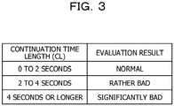
- FIG. 3 is a diagram illustrating an exemplary evaluation table according to Embodiment 1.
- the evaluation unit 160 evaluates the impression of speech of speaker A to be "normal” when the length (CL) of the continuation time is "equal to or longer than zero second and less than two seconds".
- the evaluation unit 160 evaluates the impression of speech of speaker A to be "rather bad” when the length (CL) of the continuation time is "equal to or longer than two seconds and less than four seconds”.
- the evaluation unit 160 evaluates the impression of speech of speaker A to be "significantly bad” when the length (CL) of the continuation time is "equal to or longer than four seconds”.
- Lengths of the continuation time in the evaluation table illustrated in FIG. 3 are exemplary and may be updated by an administrator as appropriate.
- the evaluation unit 160 may evaluate the impression of speech of speaker B in the same manner that for speaker A.
- the display unit 170 is a display device configured to display a result of evaluation by the evaluation unit 160.
- the display unit 170 corresponds to a liquid crystal display or a touch panel.
- the acceptance units 110a and 110b, the acquisition units 130a and 130b, the signal level calculation units 140a and 140b, and the addition unit 150, the evaluation unit 160 correspond to a control unit.
- the control unit may be achieved by, for example, a central processing unit (CPU) or a micro processing unit (MPU).
- the control unit may be achieved by a hard wired logic such as an application specific integrated circuit (ASIC) or a field programmable gate array (FPGA).
- ASIC application specific integrated circuit
- FPGA field programmable gate array
- FIG. 4 is a flowchart illustrating the procedure of processing at the evaluation device according to Embodiment 1.
- the acceptance units 110a and 110b of the evaluation device 100 record the first and second voice signals in the voice buffers 120a and 120b of the storage unit 120 (step S101).
- the signal level calculation unit 140a of the evaluation device 100 calculates the power S 1 (n) (step S102).
- the signal level calculation unit 140b of the evaluation device 100 calculates the power S 2 (n) (step S103).
- the addition unit 150 of the evaluation device 100 calculates the sum S(n) of the power S 1 (n) and the power S 2 (n) (step S104).
- the evaluation unit 160 of the evaluation device 100 calculates the continuation time CL in which the sum S(n) exceeds the threshold TH1 (step S105).
- the evaluation unit 160 evaluates the impression of conversation by speaker A (or speaker B) by comparing the continuation time CL with the evaluation table (step S106).
- the display unit 170 of the evaluation device 100 displays a result of the evaluation (step S107).
- the evaluation device 100 specifies the continuation time CL in which the sum S(n) of the power of the first voice signal S 1 (n) and the power of the second voice signal S 2 (n) exceeds the threshold TH1, and evaluates the impression of the conversation based on the continuation time CL. Accordingly, the impression of the conversation is accurately evaluated. Impression provided by interruption is correlated with the sum of the magnitudes of voice of speakers A and speaker B. It is possible to evaluate that the impression of the conversation is bad, for example, when the voice of one of the speakers is large and the voice of the other speaker is small but a time in which the sum of the magnitudes exceeds the threshold TH1 is long.
- the evaluation device 100 is capable of detecting such evaluation.
- the addition unit 150 may calculate an average S'(n) by dividing the sum S(n) by two.
- the evaluation unit 160 specifies a continuation time in which the average S'(n) exceeds a threshold TH1', and evaluates the impression of the first voice signal or the second voice signal based on the specified continuation time.
- the evaluation device 100 may further execute processing described below. For example, when speakers A and B simultaneously speak, speaker B tends to have impression that speech of speaker B is interrupted, as the voice of speaker A is larger. Thus, when comparison between the continuation time CL and the evaluation table determines impression to be "rather bad or significantly bad", the evaluation unit 160 may distinguish which of speakers A and speaker B provides bad impression based on the magnitude relation between the first and second voice signals. For example, when the first voice signal is larger than the second voice signal, the evaluation unit 160 evaluates that speaker A provides bad impression. When the second voice signal is larger than the first voice signal, the evaluation unit 160 evaluates that speaker B provides bad impression.
- FIG. 5 is a diagram illustrating an exemplary system according to Embodiment 2. As illustrated in FIG. 5 , this system includes the terminal device 50a, the terminal device 50b, and an evaluation device 200. The terminal device 50a, the terminal device 50b, and the evaluation device 200 are mutually coupled.
- the evaluation device 200 is a device configured to acquire the first and second voice signals and evaluate the impression of conversation between speakers A and B based on the first and second voice signals.
- FIG. 6 is a functional block diagram illustrating the configuration of the evaluation device according to Embodiment 2. As illustrated in FIG. 6 , this evaluation device 200 includes acceptance units 210a and 210b, a storage unit 220, acquisition units 230a and 230b, and signal level calculation units 240a and 240b. The evaluation device 200 includes an addition unit 250, an evaluation unit 260, and a display unit 270.
- the acceptance unit 210a is a processing unit configured to accept the first voice signal from the terminal device 50a.
- the acceptance unit 210a registers the first voice signal to a voice buffer 220a of the storage unit 220.
- the acceptance unit 210b is a processing unit configured to accept the second voice signal from the terminal device 50b.
- the acceptance unit 210b registers the second voice signal to a voice buffer 220b of the storage unit 220.
- the storage unit 220 includes the voice buffer 220a and the voice buffer 220b.
- the storage unit 220 corresponds to a semiconductor memory element such as a RAM, a ROM, or a flash memory, or a storage device such as a HDD.
- the voice buffer 220a is a buffer configured to store the first voice signal.
- the voice buffer 220b is a buffer configured to store the second voice signal.
- the acquisition unit 230a is a processing unit configured to acquire the first voice signal stored in the voice buffer 220a and output the acquired first voice signal to the signal level calculation unit 240a.
- the acquisition unit 230b is a processing unit configured to acquire the second voice signal stored in the voice buffer 220b and output the acquired second voice signal to the signal level calculation unit 240b.
- the signal level calculation unit 240a is a processing unit configured to calculate the signal to noise ratio (SNR) of the first voice signal. The following describes exemplary processing at the signal level calculation unit 240a.
- the signal level calculation unit 240a divides the first voice signal into a plurality of frames each having a predetermined length, and calculates the power S 1 (n) for each frame. Similarly to the signal level calculation unit 140a, the signal level calculation unit 240a calculates the power S 1 (n) based on Expression (1).
- the signal level calculation unit 240a determines the existence of a speech interval based on the power S 1 (n). For example, when Condition 3 is satisfied, the signal level calculation unit 240a determines that speech exists in the n-th frame. When Condition 3 is not satisfied, the signal level calculation unit 240a determines that no speech exists in the n-th frame. S 1 n > TH 1
- the signal level calculation unit 240a updates a noise level N 1 (n) based on the existence of speech. Specifically, when speech exists, the signal level calculation unit 240a updates the noise level N 1 (n) based on Expression (5). When no speech exists, the signal level calculation unit 240a updates the noise level N 1 (n) based on Expression (6).
- COF 1 represents a forgetting coefficient for calculating a long-term power average. For example, COF 1 is "0.9". The use of the forgetting coefficient allows the long-term power average of a frame with no speech to be calculated as a noise level.
- N 1 n N 1 n ⁇ 1 ⁇ COF 1 + S 1 n ⁇ 1 ⁇ COF 1
- N 1 n N 1 n ⁇ 1
- the signal level calculation unit 240a calculates SNR 1 (n) from the difference between the power S 1 (n) and the noise level N 1 (n). Specifically, the signal level calculation unit 240a calculates SNR 1 (n) based on Expression (7). The signal level calculation unit 240a outputs SNR 1 (n) to the addition unit 250.
- SNR 1 n S 1 n ⁇ N 1 n
- the signal level calculation unit 240b is a processing unit configured to calculate the SNR of the second voice signal. The following describes exemplary processing at the signal level calculation unit 240b.
- the signal level calculation unit 240b divides the second voice signal into a plurality of frames each having a predetermined length, and calculates the power S 2 (n) for each frame. Similarly to the signal level calculation unit 140b, the signal level calculation unit 240b calculates the power S 2 (n) based on Expression (2).
- the signal level calculation unit 240b determines the existence of a speech interval based on the power S 2 (n). For example, the signal level calculation unit 240b determines that speech exists in the n-th frame when Condition 4 is satisfied. When Condition 4 is not satisfied, the signal level calculation unit 240b determines that no speech exists in the n-th frame. S 2 n > TH 1
- the signal level calculation unit 240b updates a noise level N 2 (n) based on the existence of speech. Specifically, when speech exists, the signal level calculation unit 240b updates the noise level N 2 (n) based on Expression (8). When no speech exists, the signal level calculation unit 240b updates the noise level N 2 (n) based on Expression (9).
- Expression (8) COF 2 represents a forgetting coefficient for calculating a long-term power average. For example, COF 2 is "0.9".
- the signal level calculation unit 240b calculates SNR 2 (n) from the difference between the power S 2 (n) and the noise level N 2 (n). Specifically, the signal level calculation unit 240b calculates SNR 2 (n) based on Expression (10). The signal level calculation unit 240b outputs SNR 2 (n) to the addition unit 250.
- SNR 2 n S 2 n ⁇ N 2 n
- the addition unit 250 is a processing unit configured to add SNR 1 (n) and SNR 2 (n). For example, the addition unit 250 calculates the sum SNR(n) of SNR 1 (n) and SNR 2 (n) based on Expression (11). The addition unit 250 outputs the sum SNR(n) to the evaluation unit 260.
- SNR n SNR 1 n + SNR 2 n
- the evaluation unit 260 is a processing unit configured to calculate a frequency that the sum SNR(n) exceeds a threshold TH2, and evaluate the impression of the first voice signal or the second voice signal based on the frequency.
- the evaluation unit 260 outputs a result of the evaluation to the display unit 270.
- the following describes exemplary processing at the evaluation unit 260.
- the evaluation unit 260 calculates a frequency R(i) based on Expression (12).
- i represents the serial number of a unit time
- L represents the frame length of a unit time.
- the frame length of a unit time is 10 seconds.
- the evaluation unit 260 may calculate the frequency R(i) by using Expression (13) in place of Expression (12). For example, the total number of frames in the i-th unit time L is 500.
- R(i) "the number of frames in which the sum SNR(n) exceeds the threshold TH2" / "the total number of frames in the i-th unit time L" in the i-th unit time L ... (13)
- the evaluation unit 260 evaluates the impression of speech of speaker A by comparing the frequency R(i) with a predetermined threshold. For example, the evaluation unit 260 evaluates the impression of speech of speaker A by using an evaluation table.
- FIG. 7 is a diagram illustrating an exemplary evaluation table according to Embodiment 2.
- the evaluation unit 260 evaluates the impression of speech of speaker A to be "normal” when the frequency R(i) is "equal to or higher than X1 and lower than X2".
- the evaluation unit 260 evaluates the impression of speech of speaker A to be "rather bad” when the frequency R(i) is “equal to or higher than X2 and lower than X3".
- the evaluation unit 260 evaluates the impression of speech of speaker A to be "significantly bad” when the frequency R(i) is "equal to or higher than X3".
- XI, X2, and X3 have a magnitude relation of X1 ⁇ X2 ⁇ X3.
- the evaluation unit 260 may evaluate the impression of speech of speaker B in a manner same as that for speaker A.
- the evaluation unit 260 may exclude any certain interval in advance.
- a continuation time in which the sum SNR(n) exceeds the threshold TH2 is shorter than a predetermined threshold (for example, one seconds).
- a predetermined threshold for example, one seconds.
- the display unit 270 is a display device configured to display a result of the evaluation by the evaluation unit 260.
- the display unit 270 corresponds to a liquid crystal display or a touch panel.
- the acceptance units 210a and 210b, the acquisition units 230a and 230b, the signal level calculation units 240a and 240b, the addition unit 250, and the evaluation unit 260 correspond to a control unit.
- the control unit may be achieved by, for example, a CPU or an MPU.
- the control unit may be achieved by a hard wired logic such as an ASIC or an FPGA.
- FIG. 8 is a flowchart illustrating the procedure of processing at the evaluation device according to Embodiment 2.
- the acceptance units 210a and 210b of the evaluation device 200 record the first and second voice signals in the voice buffers 220a and 220b of the storage unit 220 (step S201).
- the signal level calculation unit 240a of the evaluation device 200 calculates SNR 1 (n) (step S202).
- the signal level calculation unit 240b of the evaluation device 200 calculates SNR 2 (n) (step S203).
- the addition unit 250 of the evaluation device 200 calculates the sum SNR(n) of SNR 1 (n) and SNR 2 (n) (step S204).
- the evaluation unit 260 of the evaluation device 200 calculates the frequency R(i) that the sum SNR(n) exceeds the threshold TH2 (step S205).
- the evaluation unit 260 evaluates the impression of conversation by speaker A (or speaker B) by comparing the frequency R(i) with an evaluation table (step S206).
- the display unit 270 of the evaluation device 200 displays a result of the evaluation (step S207).
- the evaluation device 200 specifies the frequency R(i) that the sum SNR(n) of SNR 1 (n) of the first voice signal and SNR 2 (n) of the second voice signal exceeds the threshold TH2, and evaluates the impression of the conversation based on the frequency R(i). Accordingly, the impression of the conversation is accurately evaluated. For example, it is possible to evaluate that the impression of the conversation is bad when the voice of one of the speakers is large and the voice of the other speaker is small but the frequency that the sum SNR(n) exceeds the threshold TH2 is high.
- the evaluation device 200 is capable of detecting such evaluation.
- the addition unit 250 may calculate an average SNR'(n) by dividing the sum SNR(n) by two.
- the evaluation unit 260 specifies a frequency that the average SNR'(n) exceeds a threshold TH2', and evaluates the impression of the first voice signal or the second voice signal based on the specified frequency.
- the evaluation unit 260 may exclude predetermined durations at start and end of a speech interval. For example, the evaluation unit 260 specifies a frequency that the sum SNR(n) or the average SNR'(n) exceeds a predetermined threshold in a time slot between a first time a predetermined time after the time of start of a speech interval and a second time a predetermined time before the time of end of the speech interval.
- FIG. 9 is a diagram illustrating an exemplary system according to Embodiment 3. As illustrated in FIG. 9 , this system includes the terminal device 50a, the terminal device 50b, and an evaluation device 300. The terminal device 50a, the terminal device 50b, and the evaluation device 300 are mutually coupled.
- Embodiment 3 describes an example in which speaker A is an operator, and speaker B is a customer.
- the evaluation device 300 is a device configured to acquire the first and second voice signals and evaluate the impression of conversation between speakers A and B based on the first and second voice signals.
- FIG. 10 is a functional block diagram illustrating the configuration of the evaluation device according to Embodiment 3.
- the evaluation device 300 includes acceptance units 310a and 310b, a storage unit 320, acquisition units 330a and 330b, and signal level calculation units 340a and 340b.
- the evaluation device 300 includes an addition unit 350, an evaluation unit 360, and a display unit 370.
- the acceptance unit 310a is a processing unit configured to accept the first voice signal from the terminal device 50a.
- the acceptance unit 310a registers the first voice signal to a voice buffer 320a of the storage unit 320.
- the acceptance unit 310b is a processing unit configured to accept the second voice signal from the terminal device 50b.
- the acceptance unit 310b registers the second voice signal to a voice buffer 320b of the storage unit 320.
- the storage unit 320 includes the voice buffer 320a and the voice buffer 320b.
- the storage unit 320 corresponds to a semiconductor memory element such as a RAM, a ROM, or a flash memory, or a storage device such as a HDD.
- the voice buffer 320a is a buffer configured to store the first voice signal.
- the voice buffer 320b is a buffer configured to store the second voice signal.
- the acquisition unit 330a is a processing unit configured to acquire the first voice signal stored in the voice buffer 320a and output the acquired first voice signal to the signal level calculation unit 340a.
- the acquisition unit 330b is a processing unit configured to acquire the second voice signal stored in the voice buffer 320b and output the acquired second voice signal to the signal level calculation unit 340b.
- FIG. 11 is a diagram illustrating the relation between the autocorrelation and the shift amount.
- the vertical axis represents the value of the autocorrelation
- the horizontal axis represents the shift amount.
- the autocorrelation takes the maximum value (autocorrelation value AC 1 (n)) when the shift amount is j ⁇ .
- the signal level calculation unit 340a outputs the autocorrelation value AC 1 (n) to the addition unit 350.
- the signal level calculation unit 340b outputs the autocorrelation value AC 2 (n) to the addition unit 350.
- the addition unit 350 is a processing unit configured to perform weighting on the autocorrelation value AC 1 (n) and the autocorrelation value AC 2 (n) and then add the autocorrelation value AC 1 (n) and the autocorrelation value AC 2 (n). For example, the addition unit 350 calculates a sum AC(n) based on Expression (16). The addition unit 350 outputs the sum AC(n) to the evaluation unit 360.
- AC n k 1 ⁇ AC 1 n + k 2 ⁇ AC 2 n
- k 1 and k 2 represent weighting coefficients. For example, k 1 is 1.5 and k 2 is 0.5.
- the evaluation unit 360 is a processing unit configured to calculate a frequency that the sum AC(n) exceeds a threshold TH3 and evaluate the impression of the first voice signal or the second voice signal based on the frequency.
- the evaluation unit 360 outputs a result of the evaluation to the display unit 370.
- the following describes exemplary processing at the evaluation unit 360.
- the evaluation unit 360 calculates the frequency R(i) based on Expression (17).
- i represents the serial number of a unit time
- L represents the frame length of a unit time.
- the frame length of a unit time is 10 seconds.
- the evaluation unit 360 may calculate the frequency R(i) by using Expression (18) in place of Expression (17).
- the total number of frames in the i-th unit time L is 500.
- R i " the number of frames in which the sum AC n eceeds the threshold TH 3 " / " the total number of frames in the i ⁇ th unit time L " in the i ⁇ th unit time L
- the evaluation unit 360 evaluates the impression of speech of speaker A by comparing the frequency R(i) with a predetermined threshold. For example, the evaluation unit 360 evaluates the impression of speech of speaker A by using an evaluation table.
- the evaluation table corresponds to the evaluation table described with reference to FIG. 7 .
- the evaluation unit 260 may evaluate the impression of speech of speaker B in a manner same as that of speaker A.
- the evaluation unit 360 may exclude any certain interval in advance.
- a continuation time in which the sum AC(n) exceeds the threshold TH3 is shorter than a predetermined threshold (for example, one second).
- a predetermined threshold for example, one second.
- the display unit 370 is a display device configured to display a result of the evaluation by the evaluation unit 360.
- the display unit 370 corresponds to a liquid crystal display or a touch panel.
- the acceptance units 310a and 310b, the acquisition units 330a and 330b, the signal level calculation units 340a and 340b, the addition unit 350, and the evaluation unit 360 correspond to a control unit.
- the control unit may be achieved by, for example, a CPU or a MPU.
- the control unit may be achieved by a hard wired logic such as an ASIC or an FPGA.
- FIG. 12 is a flowchart illustrating the procedure of processing at the evaluation device according to Embodiment 3.
- the acceptance units 310a and 310b of the evaluation device 300 record the first and second voice signals in the voice buffers 320a and 320b of the storage unit 320 (step S301).
- the signal level calculation unit 340a of the evaluation device 300 calculates AC 1 (n) (step S302).
- the signal level calculation unit 340b of the evaluation device 300 calculates AC 2 (n) (step S303).
- the addition unit 350 of the evaluation device 300 multiplies AC 1 (n) by the weight k 1 (step S304).
- the addition unit 350 multiplies AC 2 (n) by the weight k 2 (step S305).
- the addition unit 350 calculates the sum AC(n) (step S306).
- the evaluation unit 360 of the evaluation device 300 calculates the frequency R(i) that the sum AC(n) exceeds the threshold TH3 (step S307).
- the evaluation unit 360 evaluates the impression of conversation by speaker A (or speaker B) by comparing the frequency R(i) with an evaluation table (step S308).
- the display unit 370 of the evaluation device 300 displays a result of the evaluation (step S309).
- the evaluation device 300 specifies the frequency R(i) that the sum AC(n) of AC 1 (n) of the first voice signal and AC 2 (n) of the second voice signal exceeds the threshold TH3, and evaluates the impression of the conversation based on the frequency R(i). Accordingly, the impression of the conversation is accurately evaluated. For example, it is possible to evaluate that the impression of the conversation is bad when the voice of one of the speakers is large and the voice of the other speaker is small but the frequency that the sum AC(n) exceeds the threshold TH3 is high.
- the evaluation device 300 is capable of detecting such evaluation.
- the addition unit 350 may calculate an average AC'(n) by dividing the sum AC(n) by two.
- the evaluation unit 360 specifies a frequency that the average AC'(n) exceeds a threshold TH3', and evaluates the impression of the first voice signal or the second voice signal based on the specified frequency.
- FIG. 13 is a diagram illustrating an exemplary hardware configuration of the computer configured to achieve the functions same as those of the evaluation device.
- a computer 400 includes a CPU 401 configured to execute various kinds of arithmetic processing, an input device 402 configured to accept inputting of data from a user, and a display 403.
- the computer 400 also includes a reading device 404 configured to read a computer program or the like from a storage medium, and an interface device 405 configured to communicate data with an external device.
- the computer 400 also includes a RAM 406 configured to temporarily store various kinds of information, and a hard disk device 407.
- the devices 401 to 407 are coupled with a bus 408.
- the hard disk device 407 includes a signal level calculation program 407a, an addition program 407b, and an evaluation program 407c.
- the CPU 401 reads and loads the signal level calculation program 407a, the addition program 407b, and the evaluation program 407c onto the RAM 406.
- the signal level calculation program 407a functions as a signal level calculation process 406a.
- the addition program 407b functions as an addition process 406b.
- the evaluation program 407c functions as an evaluation process 406c.
- Processing at the signal level calculation process 406a corresponds to the processing at the signal level calculation units 140a and 140b (240a and 240b; 340a and 340b). Processing at the addition process 406b corresponds to the processing at the addition unit 150 (250, 350). Processing at the evaluation process 406c corresponds to the processing at the evaluation unit 160 (260, 360).
- the programs 407a to 407c do not necessarily have to be stored in the hard disk device 407 from the start.
- each program is stored in a "portable physical medium" to be inserted into the computer 400, such as a flexible disk (FD), a CD-ROM, a DVD disk, a magneto-optical disc, or an IC card. Then, the programs 407a to 407c may be each read and executed by the computer 400.
- a "portable physical medium” such as a flexible disk (FD), a CD-ROM, a DVD disk, a magneto-optical disc, or an IC card.
Abstract
Description
- The embodiments discussed herein are related to an information processing apparatus, a method and a program.
- In the recent conventional technology, the impression of conversation is evaluated from voice of speakers to support execution of smooth communication.
-
FIG. 14 is a diagram for description of an exemplary conventional technology. The following describes an example in which the impression of conversation speaker A and speaker B is evaluated. As illustrated inFIG. 14 , adevice 10 according to the conventional technology includes speechinterval detection units time calculation unit 12, and adetermination unit 13. - The speech
interval detection unit 11a is a processing unit configured to detect the interval of speech of speaker A from voice of speaker A. The speechinterval detection unit 11a outputs information on the speech interval of speaker A to the overlappingtime calculation unit 12. - The speech
interval detection unit 11b is a processing unit configured to detect the interval of speech of speaker B from voice of speaker B. The speechinterval detection unit 11b outputs information on the speech interval of speaker B to the overlappingtime calculation unit 12. - The overlapping
time calculation unit 12 is a processing unit configured to calculate an overlapping time between the speech interval of speaker A and the speech interval of speaker B.FIG. 15 is a diagram for description of processing at the overlapping time calculation unit. As illustrated inFIG. 15 , when the speech interval of speaker A extends from Ta1 to Ta2 and the speech interval of speaker B extends from Tb1 to Tb2, the overlapping time is Tb2 - Tb1. The overlappingtime calculation unit 12 outputs information on the overlapping time to thedetermination unit 13. - The
determination unit 13 is a processing unit configured to evaluate conversation between speakers A and B based on the overlapping time. For example, when the overlapping time is equal to or longer than a predetermined time, thedetermination unit 13 evaluates that the speech of speaker A is interrupted by speaker B or the speech of speaker B is interrupted by speaker A. A citation list includes Japanese Laid-open Patent Publication Nos.2016-133774 2006-209332 2011-254342 2002-278547 U.S. Patent Application Publication No. 2016/0217791 and2002/0172372 . - However, the conventional technology described above is unable to evaluate conversational impression related to interruption.
- For example, when speakers A and B simultaneously speak, speaker B tends to have impression that speech of speaker B is interrupted, as the voice of speaker A is larger.
- When feeling that their conversation is interrupted while making long speech, people are likely to speak an important interval as part of the speech, such as a word or a phrase, with particularly large voice. For example, in an interval in which the voice of speaker A is large while speakers A and B simultaneously speak, speaker A tends to have impression that speech of speaker A is interrupted.
- It is difficult to detect the above-described conversational impression related to interruption by comparing an overlapping time with a threshold as in the conventional technology.
- According to an aspect of the invention, an information processing apparatus includes a specifying unit configured to specify a first signal level of a first voice signal, a specifying unit configured to specify the second signal level of a second voice signal, and an evaluating unit configured to execute evaluation of at least one of the first voice signal and a second voice signal based on at least one of a sum of the first signal level and the second signal level and an average of the first signal level and the second signal level.
- The embodiments is able to evaluate conversational impression related to interruption.
-
-
FIG. 1 is a diagram illustrating an exemplary system according to Embodiment 1; -
FIG. 2 is a functional block diagram illustrating the configuration of an evaluation device according to Embodiment 1; -
FIG. 3 is a diagram illustrating an exemplary evaluation table according to Embodiment 1; -
FIG. 4 is a flowchart illustrating the procedure of processing at the evaluation device according to Embodiment 1; -
FIG. 5 is a diagram illustrating an exemplary system according toEmbodiment 2; -
FIG. 6 is a functional block diagram illustrating the configuration of an evaluation device according toEmbodiment 2; -
FIG. 7 is a diagram illustrating an exemplary evaluation table according toEmbodiment 2; -
FIG. 8 is a flowchart illustrating the procedure of processing at the evaluation device according toEmbodiment 2; -
FIG. 9 is a diagram illustrating an exemplary system according to Embodiment 3; -
FIG. 10 is a functional block diagram illustrating the configuration of an evaluation device according to Embodiment 3; -
FIG. 11 is a diagram illustrating the relation between autocorrelation and a shift amount; -
FIG. 12 is a flowchart illustrating the procedure of processing at the evaluation device according to Embodiment 3; -
FIG. 13 is a diagram illustrating an exemplary hardware configuration of a computer configured to achieve functions same as those of an evaluation device; -
FIG. 14 is a diagram for description of an exemplary conventional technology; and -
FIG. 15 is a diagram for description of processing at an overlapping time calculation unit. -
FIG. 1 is a diagram illustrating an exemplary system according to Embodiment 1. As illustrated inFIG. 1 , this system includes aterminal device 50a, aterminal device 50b, and anevaluation device 100. Theterminal device 50a, theterminal device 50b, and theevaluation device 100 are mutually coupled. - The
terminal device 50a is a terminal device used by speaker A when performing conversation with speaker B. Theterminal device 50a is coupled with aspeaker 20a and amicrophone 25a. Theterminal device 50a includes areception unit 51a and atransmission unit 52a. - The
reception unit 51a is a processing unit configured to receive a voice signal of speaker B from theterminal device 50b. Thereception unit 51a outputs voice of speaker B by outputting the voice signal of speaker B to thespeaker 20a. - The
transmission unit 52a is a processing unit configured to acquire a voice signal of speaker A collected by themicrophone 25a and output the acquired voice signal of speaker A to theterminal device 50b. - The
terminal device 50b is a terminal device used by speaker B when performing conversation with speaker A. Theterminal device 50b is coupled with aspeaker 20b and amicrophone 25b. Theterminal device 50b includes areception unit 51b and atransmission unit 52b. - The
reception unit 51b is a processing unit configured to receive a voice signal of speaker A from theterminal device 50a. Thereception unit 51b outputs voice of speaker A by outputting the voice signal of speaker A to thespeaker 20b. - The
transmission unit 52b is a processing unit configured to acquire a voice signal of speaker B collected by themicrophone 25b and output the acquired voice signal of speaker B to theterminal device 50a. - In the following description, a voice signal of speaker A is referred to as a "first voice signal", and a voice signal of speaker B is referred to as a "second voice signal".
- The
evaluation device 100 is a device configured to acquire the first voice signal and the second voice signal and evaluate impression of conversation between speakers A and B based on the first and second voice signals. -
FIG. 2 is a functional block diagram illustrating the configuration of the evaluation device according to Embodiment 1. As illustrated inFIG. 2 , thisevaluation device 100 includesacceptance units storage unit 120,acquisition units level calculation units evaluation device 100 includes anaddition unit 150, anevaluation unit 160, and adisplay unit 170. - The
acceptance unit 110a is a processing unit configured to accept the first voice signal from theterminal device 50a. Theacceptance unit 110a registers the first voice signal to avoice buffer 120a of thestorage unit 120. - The
acceptance unit 110b is a processing unit configured to accept the second voice signal from theterminal device 50b. Theacceptance unit 110b registers the second voice signal to avoice buffer 120b of thestorage unit 120. - The
storage unit 120 includes thevoice buffer 120a and thevoice buffer 120b. Thestorage unit 120 corresponds to a semiconductor memory element such as a random access memory (RAM), a read only memory (ROM), or a flash memory, or a storage device such as a hard disk drive (HDD). - The
voice buffer 120a is a buffer configured to store the first voice signal. Thevoice buffer 120b is a buffer configured to store the second voice signal. - The
acquisition unit 130a is a processing unit configured to acquire the first voice signal stored in thevoice buffer 120a and output the acquired first voice signal to the signallevel calculation unit 140a. - The
acquisition unit 130b is a processing unit configured to acquire the second voice signal stored in thevoice buffer 120b and output the acquired second voice signal to the signallevel calculation unit 140b. - The signal
level calculation unit 140a is a processing unit configured to calculate the power of the first voice signal. For example, the signallevel calculation unit 140a is a processing unit configured to divide the first voice signal into a plurality of frames each having a predetermined length and calculate a power S1(n) for each frame. The signallevel calculation unit 140a outputs the power S1(n) to theaddition unit 150. - For example, the signal
level calculation unit 140a calculates the power S1(n) based on Expression (1). In Expression (1), C1(t) represents the value of the first voice signal at time t, n represents the frame number, and M represents the time length of one frame. For example, the time length of one frame is 20 ms.
[Math 1]
- The signal
level calculation unit 140a may temporally smooth the power S1(n) by using a predetermined smoothing coefficient, and output the temporally smoothed power S1(n) to theaddition unit 150. - The signal
level calculation unit 140b is a processing unit configured to calculate the power of the second voice signal. For example, the signallevel calculation unit 140b is a processing unit configured to divide the second voice signal into a plurality of frames each having a predetermined length and calculate a power S2(n) for each frame. The signallevel calculation unit 140b outputs the power S2(n) to theaddition unit 150. - For example, the signal
level calculation unit 140b calculates the power S2(n) based on Expression (2). In Expression (2), C2(t) represents the value of the second voice signal at time t, n represents the frame number, and M represents the time length of one frame. For example, the time length of one frame is 20 ms.
[Math 2]
- The signal
level calculation unit 140b may temporally smooth the power S2(n) by using a predetermined smoothing coefficient, and output the temporally smoothed power S2(n) to theaddition unit 150. - The
addition unit 150 is a processing unit configured to add the power of the first voice signal S1(n) and the power of the second voice signal S2(n). For example, theaddition unit 150 calculates a sum S(n) of each frame based on Expression (3). Theaddition unit 150 outputs the sum S(n) to theevaluation unit 160.
- The
evaluation unit 160 is a processing unit configured to specify a continuation time in which the sum S(n) exceeds a threshold TH1, and evaluate impression of the first voice signal or the second voice signal based on the specified continuation time. Theevaluation unit 160 outputs a result of the evaluation to thedisplay unit 170. The following describes exemplary processing at theevaluation unit 160. - The
evaluation unit 160 calculates a start frame Ts at which the sum S(n) exceeds the threshold TH1. For example, theevaluation unit 160 specifies the frame number n of a frame satisfying Condition 1 below and sets the specified frame number n to the start frame Ts. The threshold TH1 is 20 dB.
- After having specified the start frame Ts, the
evaluation unit 160 calculates an end frame Te at which the sum S(n) becomes equal to or smaller than the threshold TH1. For example, theevaluation unit 160 specifies the frame number n of aframe satisfying Condition 2, and sets the frame number n-1 to the end frame Te.
- The
evaluation unit 160 calculates a continuation time CL based on the difference between the start frame Ts and the end frame Te. For example, theevaluation unit 160 calculates the continuation time CL based on Expression (4).
- The
evaluation unit 160 evaluates the impression of speech of speaker A by comparing the continuation time CL with a predetermined threshold. For example, theevaluation unit 160 evaluates the impression of speech of speaker A by using an evaluation table. Alternatively, theevaluation unit 160 may calculate a ratio of the powers of the first and second voice signals and specify a speaker as an evaluation target based on the ratio. For example, when the ratio is higher for the power of the first voice signal corresponding to speaker A, the impression of speech may be evaluated for speaker A. -
FIG. 3 is a diagram illustrating an exemplary evaluation table according to Embodiment 1. As illustrated inFIG. 3 , theevaluation unit 160 evaluates the impression of speech of speaker A to be "normal" when the length (CL) of the continuation time is "equal to or longer than zero second and less than two seconds". Theevaluation unit 160 evaluates the impression of speech of speaker A to be "rather bad" when the length (CL) of the continuation time is "equal to or longer than two seconds and less than four seconds". Theevaluation unit 160 evaluates the impression of speech of speaker A to be "significantly bad" when the length (CL) of the continuation time is "equal to or longer than four seconds". - Lengths of the continuation time in the evaluation table illustrated in
FIG. 3 are exemplary and may be updated by an administrator as appropriate. Theevaluation unit 160 may evaluate the impression of speech of speaker B in the same manner that for speaker A. - The
display unit 170 is a display device configured to display a result of evaluation by theevaluation unit 160. For example, thedisplay unit 170 corresponds to a liquid crystal display or a touch panel. - For example, the
acceptance units acquisition units level calculation units addition unit 150, theevaluation unit 160 correspond to a control unit. The control unit may be achieved by, for example, a central processing unit (CPU) or a micro processing unit (MPU). Alternatively, the control unit may be achieved by a hard wired logic such as an application specific integrated circuit (ASIC) or a field programmable gate array (FPGA). - The following describes an exemplary procedure of processing at the
evaluation device 100 according to Embodiment 1.FIG. 4 is a flowchart illustrating the procedure of processing at the evaluation device according to Embodiment 1. As illustrated inFIG. 4 , theacceptance units evaluation device 100 record the first and second voice signals in the voice buffers 120a and 120b of the storage unit 120 (step S101). - The signal
level calculation unit 140a of theevaluation device 100 calculates the power S1(n) (step S102). The signallevel calculation unit 140b of theevaluation device 100 calculates the power S2(n) (step S103). - The
addition unit 150 of theevaluation device 100 calculates the sum S(n) of the power S1(n) and the power S2(n) (step S104). Theevaluation unit 160 of theevaluation device 100 calculates the continuation time CL in which the sum S(n) exceeds the threshold TH1 (step S105). - The
evaluation unit 160 evaluates the impression of conversation by speaker A (or speaker B) by comparing the continuation time CL with the evaluation table (step S106). Thedisplay unit 170 of theevaluation device 100 displays a result of the evaluation (step S107). - The following describes effects achieved by the
evaluation device 100 according to Embodiment 1. Theevaluation device 100 specifies the continuation time CL in which the sum S(n) of the power of the first voice signal S1(n) and the power of the second voice signal S2(n) exceeds the threshold TH1, and evaluates the impression of the conversation based on the continuation time CL. Accordingly, the impression of the conversation is accurately evaluated. Impression provided by interruption is correlated with the sum of the magnitudes of voice of speakers A and speaker B. It is possible to evaluate that the impression of the conversation is bad, for example, when the voice of one of the speakers is large and the voice of the other speaker is small but a time in which the sum of the magnitudes exceeds the threshold TH1 is long. Theevaluation device 100 is capable of detecting such evaluation. - The
addition unit 150 may calculate an average S'(n) by dividing the sum S(n) by two. In such a case, theevaluation unit 160 specifies a continuation time in which the average S'(n) exceeds a threshold TH1', and evaluates the impression of the first voice signal or the second voice signal based on the specified continuation time. - The
evaluation device 100 may further execute processing described below. For example, when speakers A and B simultaneously speak, speaker B tends to have impression that speech of speaker B is interrupted, as the voice of speaker A is larger. Thus, when comparison between the continuation time CL and the evaluation table determines impression to be "rather bad or significantly bad", theevaluation unit 160 may distinguish which of speakers A and speaker B provides bad impression based on the magnitude relation between the first and second voice signals. For example, when the first voice signal is larger than the second voice signal, theevaluation unit 160 evaluates that speaker A provides bad impression. When the second voice signal is larger than the first voice signal, theevaluation unit 160 evaluates that speaker B provides bad impression. -
FIG. 5 is a diagram illustrating an exemplary system according toEmbodiment 2. As illustrated inFIG. 5 , this system includes theterminal device 50a, theterminal device 50b, and anevaluation device 200. Theterminal device 50a, theterminal device 50b, and theevaluation device 200 are mutually coupled. - Description of the
terminal devices terminal devices - The
evaluation device 200 is a device configured to acquire the first and second voice signals and evaluate the impression of conversation between speakers A and B based on the first and second voice signals. -
FIG. 6 is a functional block diagram illustrating the configuration of the evaluation device according toEmbodiment 2. As illustrated inFIG. 6 , thisevaluation device 200 includesacceptance units storage unit 220,acquisition units level calculation units evaluation device 200 includes anaddition unit 250, anevaluation unit 260, and adisplay unit 270. - The
acceptance unit 210a is a processing unit configured to accept the first voice signal from theterminal device 50a. Theacceptance unit 210a registers the first voice signal to avoice buffer 220a of thestorage unit 220. - The
acceptance unit 210b is a processing unit configured to accept the second voice signal from theterminal device 50b. Theacceptance unit 210b registers the second voice signal to avoice buffer 220b of thestorage unit 220. - The
storage unit 220 includes thevoice buffer 220a and thevoice buffer 220b. Thestorage unit 220 corresponds to a semiconductor memory element such as a RAM, a ROM, or a flash memory, or a storage device such as a HDD. - The
voice buffer 220a is a buffer configured to store the first voice signal. Thevoice buffer 220b is a buffer configured to store the second voice signal. - The
acquisition unit 230a is a processing unit configured to acquire the first voice signal stored in thevoice buffer 220a and output the acquired first voice signal to the signallevel calculation unit 240a. - The
acquisition unit 230b is a processing unit configured to acquire the second voice signal stored in thevoice buffer 220b and output the acquired second voice signal to the signallevel calculation unit 240b. - The signal
level calculation unit 240a is a processing unit configured to calculate the signal to noise ratio (SNR) of the first voice signal. The following describes exemplary processing at the signallevel calculation unit 240a. - The signal
level calculation unit 240a divides the first voice signal into a plurality of frames each having a predetermined length, and calculates the power S1(n) for each frame. Similarly to the signallevel calculation unit 140a, the signallevel calculation unit 240a calculates the power S1(n) based on Expression (1). - The signal
level calculation unit 240a determines the existence of a speech interval based on the power S1(n). For example, when Condition 3 is satisfied, the signallevel calculation unit 240a determines that speech exists in the n-th frame. When Condition 3 is not satisfied, the signallevel calculation unit 240a determines that no speech exists in the n-th frame.
- The signal
level calculation unit 240a updates a noise level N1(n) based on the existence of speech. Specifically, when speech exists, the signallevel calculation unit 240a updates the noise level N1(n) based on Expression (5). When no speech exists, the signallevel calculation unit 240a updates the noise level N1(n) based on Expression (6). In Expression (5), COF1 represents a forgetting coefficient for calculating a long-term power average. For example, COF1 is "0.9". The use of the forgetting coefficient allows the long-term power average of a frame with no speech to be calculated as a noise level.

- The signal
level calculation unit 240a calculates SNR1(n) from the difference between the power S1(n) and the noise level N1(n). Specifically, the signallevel calculation unit 240a calculates SNR1(n) based on Expression (7). The signallevel calculation unit 240a outputs SNR1(n) to theaddition unit 250.
- The signal
level calculation unit 240b is a processing unit configured to calculate the SNR of the second voice signal. The following describes exemplary processing at the signallevel calculation unit 240b. - The signal
level calculation unit 240b divides the second voice signal into a plurality of frames each having a predetermined length, and calculates the power S2(n) for each frame. Similarly to the signallevel calculation unit 140b, the signallevel calculation unit 240b calculates the power S2(n) based on Expression (2). - The signal
level calculation unit 240b determines the existence of a speech interval based on the power S2(n). For example, the signallevel calculation unit 240b determines that speech exists in the n-th frame whenCondition 4 is satisfied. WhenCondition 4 is not satisfied, the signallevel calculation unit 240b determines that no speech exists in the n-th frame.
- The signal
level calculation unit 240b updates a noise level N2(n) based on the existence of speech. Specifically, when speech exists, the signallevel calculation unit 240b updates the noise level N2(n) based on Expression (8). When no speech exists, the signallevel calculation unit 240b updates the noise level N2(n) based on Expression (9). In Expression (8), COF2 represents a forgetting coefficient for calculating a long-term power average. For example, COF2 is "0.9".

- The signal
level calculation unit 240b calculates SNR2(n) from the difference between the power S2(n) and the noise level N2(n). Specifically, the signallevel calculation unit 240b calculates SNR2(n) based on Expression (10). The signallevel calculation unit 240b outputs SNR2(n) to theaddition unit 250.
- The
addition unit 250 is a processing unit configured to add SNR1(n) and SNR2(n). For example, theaddition unit 250 calculates the sum SNR(n) of SNR1(n) and SNR2(n) based on Expression (11). Theaddition unit 250 outputs the sum SNR(n) to theevaluation unit 260.
- The
evaluation unit 260 is a processing unit configured to calculate a frequency that the sum SNR(n) exceeds a threshold TH2, and evaluate the impression of the first voice signal or the second voice signal based on the frequency. Theevaluation unit 260 outputs a result of the evaluation to thedisplay unit 270. The following describes exemplary processing at theevaluation unit 260. - The
evaluation unit 260 calculates a frequency R(i) based on Expression (12). In Expression (12), i represents the serial number of a unit time, and L represents the frame length of a unit time. For example, the frame length of a unit time is 10 seconds.
[Math 3]
- The
evaluation unit 260 may calculate the frequency R(i) by using Expression (13) in place of Expression (12). For example, the total number of frames in the i-th unit time L is 500. - R(i) = "the number of frames in which the sum SNR(n) exceeds the threshold TH2" / "the total number of frames in the i-th unit time L" in the i-th unit time L ... (13)
- The
evaluation unit 260 evaluates the impression of speech of speaker A by comparing the frequency R(i) with a predetermined threshold. For example, theevaluation unit 260 evaluates the impression of speech of speaker A by using an evaluation table. -
FIG. 7 is a diagram illustrating an exemplary evaluation table according toEmbodiment 2. As illustrated inFIG. 7 , theevaluation unit 260 evaluates the impression of speech of speaker A to be "normal" when the frequency R(i) is "equal to or higher than X1 and lower than X2". Theevaluation unit 260 evaluates the impression of speech of speaker A to be "rather bad" when the frequency R(i) is "equal to or higher than X2 and lower than X3". Theevaluation unit 260 evaluates the impression of speech of speaker A to be "significantly bad" when the frequency R(i) is "equal to or higher than X3". For example, inFIG. 7 , XI, X2, and X3 have a magnitude relation of X1 < X2 < X3. - The
evaluation unit 260 may evaluate the impression of speech of speaker B in a manner same as that for speaker A. - When calculating the frequency R(i), the
evaluation unit 260 may exclude any certain interval in advance. In this internal, a continuation time in which the sum SNR(n) exceeds the threshold TH2 is shorter than a predetermined threshold (for example, one seconds). Such an interval includes short speech such as backchannels of "yes", "right", and the like, and thus it is possible to improve the accuracy of impression evaluation by excluding speech in the interval. - The
display unit 270 is a display device configured to display a result of the evaluation by theevaluation unit 260. For example, thedisplay unit 270 corresponds to a liquid crystal display or a touch panel. - For example, the
acceptance units acquisition units level calculation units addition unit 250, and theevaluation unit 260 correspond to a control unit. The control unit may be achieved by, for example, a CPU or an MPU. Alternatively, the control unit may be achieved by a hard wired logic such as an ASIC or an FPGA. - The following describes an exemplary procedure of processing at the
evaluation device 200 according toEmbodiment 2.FIG. 8 is a flowchart illustrating the procedure of processing at the evaluation device according toEmbodiment 2. As illustrated inFIG. 8 , theacceptance units evaluation device 200 record the first and second voice signals in the voice buffers 220a and 220b of the storage unit 220 (step S201). - The signal
level calculation unit 240a of theevaluation device 200 calculates SNR1(n) (step S202). The signallevel calculation unit 240b of theevaluation device 200 calculates SNR2(n) (step S203). - The
addition unit 250 of theevaluation device 200 calculates the sum SNR(n) of SNR1(n) and SNR2(n) (step S204). Theevaluation unit 260 of theevaluation device 200 calculates the frequency R(i) that the sum SNR(n) exceeds the threshold TH2 (step S205). - The
evaluation unit 260 evaluates the impression of conversation by speaker A (or speaker B) by comparing the frequency R(i) with an evaluation table (step S206). Thedisplay unit 270 of theevaluation device 200 displays a result of the evaluation (step S207). - The following describes effects achieved by the
evaluation device 200 according toEmbodiment 2. Theevaluation device 200 specifies the frequency R(i) that the sum SNR(n) of SNR1(n) of the first voice signal and SNR2(n) of the second voice signal exceeds the threshold TH2, and evaluates the impression of the conversation based on the frequency R(i). Accordingly, the impression of the conversation is accurately evaluated. For example, it is possible to evaluate that the impression of the conversation is bad when the voice of one of the speakers is large and the voice of the other speaker is small but the frequency that the sum SNR(n) exceeds the threshold TH2 is high. Theevaluation device 200 is capable of detecting such evaluation. - The
addition unit 250 may calculate an average SNR'(n) by dividing the sum SNR(n) by two. In such a case, theevaluation unit 260 specifies a frequency that the average SNR'(n) exceeds a threshold TH2', and evaluates the impression of the first voice signal or the second voice signal based on the specified frequency. - When performing the frequency calculation, the
evaluation unit 260 may exclude predetermined durations at start and end of a speech interval. For example, theevaluation unit 260 specifies a frequency that the sum SNR(n) or the average SNR'(n) exceeds a predetermined threshold in a time slot between a first time a predetermined time after the time of start of a speech interval and a second time a predetermined time before the time of end of the speech interval. -
FIG. 9 is a diagram illustrating an exemplary system according to Embodiment 3. As illustrated inFIG. 9 , this system includes theterminal device 50a, theterminal device 50b, and anevaluation device 300. Theterminal device 50a, theterminal device 50b, and theevaluation device 300 are mutually coupled. Embodiment 3 describes an example in which speaker A is an operator, and speaker B is a customer. - Description of the
terminal devices terminal devices - The
evaluation device 300 is a device configured to acquire the first and second voice signals and evaluate the impression of conversation between speakers A and B based on the first and second voice signals. -
FIG. 10 is a functional block diagram illustrating the configuration of the evaluation device according to Embodiment 3. As illustrated inFIG. 10 , theevaluation device 300 includesacceptance units storage unit 320,acquisition units level calculation units evaluation device 300 includes anaddition unit 350, anevaluation unit 360, and adisplay unit 370. - The
acceptance unit 310a is a processing unit configured to accept the first voice signal from theterminal device 50a. Theacceptance unit 310a registers the first voice signal to avoice buffer 320a of thestorage unit 320. - The
acceptance unit 310b is a processing unit configured to accept the second voice signal from theterminal device 50b. Theacceptance unit 310b registers the second voice signal to avoice buffer 320b of thestorage unit 320. - The
storage unit 320 includes thevoice buffer 320a and thevoice buffer 320b. Thestorage unit 320 corresponds to a semiconductor memory element such as a RAM, a ROM, or a flash memory, or a storage device such as a HDD. - The
voice buffer 320a is a buffer configured to store the first voice signal. Thevoice buffer 320b is a buffer configured to store the second voice signal. - The
acquisition unit 330a is a processing unit configured to acquire the first voice signal stored in thevoice buffer 320a and output the acquired first voice signal to the signallevel calculation unit 340a. - The
acquisition unit 330b is a processing unit configured to acquire the second voice signal stored in thevoice buffer 320b and output the acquired second voice signal to the signallevel calculation unit 340b. - The signal
level calculation unit 340a is a processing unit configured to calculate the value of autocorrelation of the first voice signal. For example, the signallevel calculation unit 340a calculates the autocorrelation of the first voice signal, and calculates a maximum autocorrelation value AC1(n) at a shift amount in a predetermined range. The signallevel calculation unit 340a calculates the autocorrelation value AC1(n) based on Expression (14). In Expression (14), C1(t) represents the value of the first voice signal at time t, and j represents the shift amount.
[Math 4]
-
FIG. 11 is a diagram illustrating the relation between the autocorrelation and the shift amount. InFIG. 11 , the vertical axis represents the value of the autocorrelation, and the horizontal axis represents the shift amount. In the example illustrated inFIG. 11 , the autocorrelation takes the maximum value (autocorrelation value AC1(n)) when the shift amount is jα. The signallevel calculation unit 340a outputs the autocorrelation value AC1(n) to theaddition unit 350. - The signal
level calculation unit 340b is a processing unit configured to calculate the value of autocorrelation of the second voice signal. For example, the signallevel calculation unit 340b calculates the autocorrelation of the second voice signal, and calculates a maximum autocorrelation value AC2(n) at a shift amount in a predetermined range. The signallevel calculation unit 340b calculates the autocorrelation value AC2(n) based on Expression (15). In Expression (15), C2(t) represents the value of the second voice signal at time t, and j represents the shift amount.
[Math 5]
- The signal
level calculation unit 340b outputs the autocorrelation value AC2(n) to theaddition unit 350. - The
addition unit 350 is a processing unit configured to perform weighting on the autocorrelation value AC1(n) and the autocorrelation value AC2(n) and then add the autocorrelation value AC1(n) and the autocorrelation value AC2(n). For example, theaddition unit 350 calculates a sum AC(n) based on Expression (16). Theaddition unit 350 outputs the sum AC(n) to theevaluation unit 360.
- In Expression (16), k1 and k2 represent weighting coefficients. For example, k1 is 1.5 and k2 is 0.5.
- The
evaluation unit 360 is a processing unit configured to calculate a frequency that the sum AC(n) exceeds a threshold TH3 and evaluate the impression of the first voice signal or the second voice signal based on the frequency. Theevaluation unit 360 outputs a result of the evaluation to thedisplay unit 370. The following describes exemplary processing at theevaluation unit 360. - The
evaluation unit 360 calculates the frequency R(i) based on Expression (17). In Expression (17), i represents the serial number of a unit time, and L represents the frame length of a unit time. For example, the frame length of a unit time is 10 seconds.
[Math 6]
- The
evaluation unit 360 may calculate the frequency R(i) by using Expression (18) in place of Expression (17). For example, the total number of frames in the i-th unit time L is 500.
- The
evaluation unit 360 evaluates the impression of speech of speaker A by comparing the frequency R(i) with a predetermined threshold. For example, theevaluation unit 360 evaluates the impression of speech of speaker A by using an evaluation table. For example, the evaluation table corresponds to the evaluation table described with reference toFIG. 7 . - The
evaluation unit 260 may evaluate the impression of speech of speaker B in a manner same as that of speaker A. - When calculating the frequency R(i), the
evaluation unit 360 may exclude any certain interval in advance. In this interval, a continuation time in which the sum AC(n) exceeds the threshold TH3 is shorter than a predetermined threshold (for example, one second). Such an interval includes short speech such as backchannels of "yes", "right", and the like, and thus it is possible to improve the accuracy of impression evaluation by excluding speech in the interval. - The
display unit 370 is a display device configured to display a result of the evaluation by theevaluation unit 360. For example, thedisplay unit 370 corresponds to a liquid crystal display or a touch panel. - For example, the
acceptance units acquisition units level calculation units addition unit 350, and theevaluation unit 360 correspond to a control unit. The control unit may be achieved by, for example, a CPU or a MPU. Alternatively, the control unit may be achieved by a hard wired logic such as an ASIC or an FPGA. - The following describes an exemplary procedure of processing at the
evaluation device 300 according to Embodiment 3.FIG. 12 is a flowchart illustrating the procedure of processing at the evaluation device according to Embodiment 3. As illustrated inFIG. 12 , theacceptance units evaluation device 300 record the first and second voice signals in the voice buffers 320a and 320b of the storage unit 320 (step S301). - The signal
level calculation unit 340a of theevaluation device 300 calculates AC1(n) (step S302). The signallevel calculation unit 340b of theevaluation device 300 calculates AC2(n) (step S303). - The
addition unit 350 of theevaluation device 300 multiplies AC1(n) by the weight k1 (step S304). Theaddition unit 350 multiplies AC2(n) by the weight k2 (step S305). Theaddition unit 350 calculates the sum AC(n) (step S306). - The
evaluation unit 360 of theevaluation device 300 calculates the frequency R(i) that the sum AC(n) exceeds the threshold TH3 (step S307). - The
evaluation unit 360 evaluates the impression of conversation by speaker A (or speaker B) by comparing the frequency R(i) with an evaluation table (step S308). Thedisplay unit 370 of theevaluation device 300 displays a result of the evaluation (step S309). - The following describes effects achieved by the
evaluation device 300 according to Embodiment 3. Theevaluation device 300 specifies the frequency R(i) that the sum AC(n) of AC1(n) of the first voice signal and AC2(n) of the second voice signal exceeds the threshold TH3, and evaluates the impression of the conversation based on the frequency R(i). Accordingly, the impression of the conversation is accurately evaluated. For example, it is possible to evaluate that the impression of the conversation is bad when the voice of one of the speakers is large and the voice of the other speaker is small but the frequency that the sum AC(n) exceeds the threshold TH3 is high. Theevaluation device 300 is capable of detecting such evaluation. - When the weight k1 of the autocorrelation value AC1(n) for the first voice signal of speaker A (operator) is larger than the weight k2 of the autocorrelation value AC2(n) for the second voice signal of speaker B (customer), effects as follows are obtained. Specifically, it is possible to perform impression evaluation more focused on the influence of interruption of the voice of the customer by the operator than on the influence of interruption of the voice of the operator by the customer. Accordingly, it is expected to effectively utilize the evaluation in handling training of the operator.
- The
addition unit 350 may calculate an average AC'(n) by dividing the sum AC(n) by two. In such a case, theevaluation unit 360 specifies a frequency that the average AC'(n) exceeds a threshold TH3', and evaluates the impression of the first voice signal or the second voice signal based on the specified frequency. - The following describes an exemplary hardware configuration of a computer configured to achieve functions same as those of the evaluation device 100 (200, 300) described above in the embodiments.
FIG. 13 is a diagram illustrating an exemplary hardware configuration of the computer configured to achieve the functions same as those of the evaluation device. - As illustrated in
FIG. 13 , acomputer 400 includes a CPU 401 configured to execute various kinds of arithmetic processing, an input device 402 configured to accept inputting of data from a user, and adisplay 403. Thecomputer 400 also includes a reading device 404 configured to read a computer program or the like from a storage medium, and aninterface device 405 configured to communicate data with an external device. Thecomputer 400 also includes aRAM 406 configured to temporarily store various kinds of information, and ahard disk device 407. The devices 401 to 407 are coupled with abus 408. - The
hard disk device 407 includes a signallevel calculation program 407a, anaddition program 407b, and an evaluation program 407c. The CPU 401 reads and loads the signallevel calculation program 407a, theaddition program 407b, and the evaluation program 407c onto theRAM 406. - The signal
level calculation program 407a functions as a signallevel calculation process 406a. Theaddition program 407b functions as anaddition process 406b. The evaluation program 407c functions as anevaluation process 406c. - Processing at the signal
level calculation process 406a corresponds to the processing at the signallevel calculation units addition process 406b corresponds to the processing at the addition unit 150 (250, 350). Processing at theevaluation process 406c corresponds to the processing at the evaluation unit 160 (260, 360). - The
programs 407a to 407c do not necessarily have to be stored in thehard disk device 407 from the start. For example, each program is stored in a "portable physical medium" to be inserted into thecomputer 400, such as a flexible disk (FD), a CD-ROM, a DVD disk, a magneto-optical disc, or an IC card. Then, theprograms 407a to 407c may be each read and executed by thecomputer 400. -
- 50a, 50bterminal device
- 100, 200, 300evaluation device
Claims (15)
- An information processing apparatus comprising:a specifying unit configured to specify a first signal level of a first voice signal;a specifying unit configured to specify a second signal level of a second voice signal; andan evaluating unit configured to execute evaluation of at least one of the first voice signal and the second voice signal based on at least one of a sum of the first signal level and the second signal level and an average of the first signal level and the second signal level.
- The information processing apparatus according to claim 1, wherein the information processing apparatus is configured to:specify a ratio of the first signal level and the second signal level; andexecute the evaluation on impressions of at least one of the first voice signal and the second voice signal based on the specified ratio.
- The information processing apparatus according to claim 1, wherein the information processing apparatus is configured to:specify a time period for which at least one of the sum and the average continuously exceeds a threshold; andexecute the evaluation on impressions of at least one of the first voice signal and the second voice signal based on the specified time period.
- The information processing apparatus according to claim 1, wherein the information processing apparatus is configured to:specify a frequency that at least one of the sum and the average exceeds a threshold; andexecute the evaluation on impressions of at least one of the first voice signal and the second voice signal based on the specified frequency.
- The information processing apparatus according to claim 4, wherein the information processing apparatus is configured to specify the frequency that at least one of the sum and the average exceeds the threshold in a duration excluding a time slot, the time period being shorter than a certain time length in the time slot.
- The information processing apparatus according to claim 4, wherein the processor is configured to specify the frequency that at least one of the sum and the average exceeds the threshold in a time slot between a first time a certain time after a time of start of a speech interval and a second time a certain time before a time of end of the speech interval.
- The information processing apparatus according to claim 4, wherein the information processing apparatus is configured to:specify the power of the first voice signal as the first signal level; andspecify the power of the second voice signal as the second signal level.
- The information processing apparatus according to claim 4, wherein the information processing apparatus is configured to:specify a signal to noise ratio of the first voice signal as the first signal level; andspecify a signal to noise ratio of the second voice signal as the second signal level.
- The information processing apparatus according to claim 4, wherein the information processing apparatus is configured to:specify a value of autocorrelation of the first voice signal as the first signal level; andspecify a value of autocorrelation of the second voice signal as the second signal level.
- The information processing apparatus according to claim 4, wherein the information processing apparatus is configured to:multiply the first signal level by a first coefficient;multiply the second signal level by a second coefficient different from the first coefficient; andspecify at least one of the sum and the average based on the multiplied first signal level and the multiplied second signal level.
- The information processing apparatus according to claim 4, wherein the evaluation evaluates whether a first speaker of the first voice signal interrupts speech of a second speaker of the second voice signal.
- A method executed by a computer, the method comprising:specifying a first signal level of a first voice signal;specifying a second signal level of a second voice signal; andexecuting evaluation of at least one of the first voice signal and a second voice signal based on at least one of a sum of the first signal level and the second signal level and an average of the first signal level and the second signal level.
- The method according to claim 12, further comprising:specifying a ratio of the first signal level and the second signal level; andexecuting the evaluation on impressions of at least one of the first voice signal and the second voice signal based on the specified ratio.
- The method according to claim 12, further comprising:specifying a time period for which at least one of the sum and the average continuously exceeds a threshold; andexecuting the evaluation on impressions of at least one of the first voice signal and the second voice signal based on the specified time period.
- A program that causes an information processing apparatus to execute a process, the process comprising:specifying a first signal level of a first voice signal;specifying a second signal level of a second voice signal; andexecuting evaluation of at least one of the first voice signal and the second voice signal based on at least one of a sum of the first signal level and the second signal level and an average of the first signal level and the second signal level.
Applications Claiming Priority (1)
| Application Number | Priority Date | Filing Date | Title |
|---|---|---|---|
| JP2017139228A JP7143574B2 (en) | 2017-07-18 | 2017-07-18 | Evaluation program, evaluation method and evaluation device |
Publications (2)
| Publication Number | Publication Date |
|---|---|
| EP3432302A1 true EP3432302A1 (en) | 2019-01-23 |
| EP3432302B1 EP3432302B1 (en) | 2021-10-20 |
Family
ID=63103750
Family Applications (1)
| Application Number | Title | Priority Date | Filing Date |
|---|---|---|---|
| EP18183373.2A Active EP3432302B1 (en) | 2017-07-18 | 2018-07-13 | Information processing apparatus, method and program |
Country Status (3)
| Country | Link |
|---|---|
| US (1) | US10741198B2 (en) |
| EP (1) | EP3432302B1 (en) |
| JP (1) | JP7143574B2 (en) |
Citations (8)
| Publication number | Priority date | Publication date | Assignee | Title |
|---|---|---|---|---|
| JP2002278547A (en) | 2001-03-22 | 2002-09-27 | Matsushita Electric Ind Co Ltd | Music piece retrieval method, music piece retrieval data registration method, music piece retrieval device and music piece retrieval data registration device |
| US20020172372A1 (en) | 2001-03-22 | 2002-11-21 | Junichi Tagawa | Sound features extracting apparatus, sound data registering apparatus, sound data retrieving apparatus, and methods and programs for implementing the same |
| JP2006209332A (en) | 2005-01-26 | 2006-08-10 | Nippon Telegr & Teleph Corp <Ntt> | Sense of value estimation method and device and its program |
| US20070067159A1 (en) * | 2005-09-02 | 2007-03-22 | Microsoft Corporation | Monitoring, mining, and classifying electronically recordable conversations |
| JP2011254342A (en) | 2010-06-03 | 2011-12-15 | Nippon Telegr & Teleph Corp <Ntt> | Method for editing video, device for editing video, and program for editing video |
| US8897437B1 (en) * | 2013-01-08 | 2014-11-25 | Prosodica, LLC | Method and system for improving call-participant behavior through game mechanics |
| JP2016133774A (en) | 2015-01-22 | 2016-07-25 | 富士通株式会社 | Speech processor, speech processing method and speech processing program |
| US20170061989A1 (en) * | 2015-09-02 | 2017-03-02 | International Business Machines Corporation | Conversational analytics |
Family Cites Families (9)
| Publication number | Priority date | Publication date | Assignee | Title |
|---|---|---|---|---|
| US5317567A (en) * | 1991-09-12 | 1994-05-31 | The United States Of America As Represented By The Secretary Of The Air Force | Multi-speaker conferencing over narrowband channels |
| US5737405A (en) * | 1995-07-25 | 1998-04-07 | Rockwell International Corporation | Apparatus and method for detecting conversation interruptions in a telephonic switch |
| CN1320782C (en) * | 2001-05-22 | 2007-06-06 | 三菱电机株式会社 | Echo processing appts. |
| AU2003203650A1 (en) * | 2002-01-18 | 2003-08-07 | Raytheon Company | Combining signals exhibiting multiple types of diversity |
| US7881234B2 (en) * | 2006-10-19 | 2011-02-01 | International Business Machines Corporation | Detecting interruptions in audio conversations and conferences, and using a conversation marker indicative of the interrupted conversation |
| JP2009124634A (en) * | 2007-11-19 | 2009-06-04 | Nippon Telegr & Teleph Corp <Ntt> | Objective quality evaluation apparatus and method |
| JP2010259691A (en) * | 2009-05-11 | 2010-11-18 | Panasonic Corp | Stress measuring device |
| WO2015047308A1 (en) * | 2013-09-27 | 2015-04-02 | Nuance Communications, Inc. | Methods and apparatus for robust speaker activity detection |
| JP6641832B2 (en) * | 2015-09-24 | 2020-02-05 | 富士通株式会社 | Audio processing device, audio processing method, and audio processing program |
-
2017
- 2017-07-18 JP JP2017139228A patent/JP7143574B2/en active Active
-
2018
- 2018-07-13 US US16/035,153 patent/US10741198B2/en active Active
- 2018-07-13 EP EP18183373.2A patent/EP3432302B1/en active Active
Patent Citations (9)
| Publication number | Priority date | Publication date | Assignee | Title |
|---|---|---|---|---|
| JP2002278547A (en) | 2001-03-22 | 2002-09-27 | Matsushita Electric Ind Co Ltd | Music piece retrieval method, music piece retrieval data registration method, music piece retrieval device and music piece retrieval data registration device |
| US20020172372A1 (en) | 2001-03-22 | 2002-11-21 | Junichi Tagawa | Sound features extracting apparatus, sound data registering apparatus, sound data retrieving apparatus, and methods and programs for implementing the same |
| JP2006209332A (en) | 2005-01-26 | 2006-08-10 | Nippon Telegr & Teleph Corp <Ntt> | Sense of value estimation method and device and its program |
| US20070067159A1 (en) * | 2005-09-02 | 2007-03-22 | Microsoft Corporation | Monitoring, mining, and classifying electronically recordable conversations |
| JP2011254342A (en) | 2010-06-03 | 2011-12-15 | Nippon Telegr & Teleph Corp <Ntt> | Method for editing video, device for editing video, and program for editing video |
| US8897437B1 (en) * | 2013-01-08 | 2014-11-25 | Prosodica, LLC | Method and system for improving call-participant behavior through game mechanics |
| JP2016133774A (en) | 2015-01-22 | 2016-07-25 | 富士通株式会社 | Speech processor, speech processing method and speech processing program |
| US20160217791A1 (en) | 2015-01-22 | 2016-07-28 | Fujitsu Limited | Voice processing device and voice processing method |
| US20170061989A1 (en) * | 2015-09-02 | 2017-03-02 | International Business Machines Corporation | Conversational analytics |
Non-Patent Citations (1)
| Title |
|---|
| KOFI BOAKYE ET AL: "Overlapped speech detection for improved speaker diarization in multiparty meetings", ACOUSTICS, SPEECH AND SIGNAL PROCESSING, 2008. ICASSP 2008. IEEE INTERNATIONAL CONFERENCE ON, IEEE, PISCATAWAY, NJ, USA, 31 March 2008 (2008-03-31), pages 4353 - 4356, XP031251561, ISBN: 978-1-4244-1483-3 * |
Also Published As
| Publication number | Publication date |
|---|---|
| JP2019020600A (en) | 2019-02-07 |
| US10741198B2 (en) | 2020-08-11 |
| US20190027165A1 (en) | 2019-01-24 |
| EP3432302B1 (en) | 2021-10-20 |
| JP7143574B2 (en) | 2022-09-29 |
Similar Documents
| Publication | Publication Date | Title |
|---|---|---|
| JP6999012B2 (en) | Audio signal detection method and equipment | |
| US9396739B2 (en) | Method and apparatus for detecting voice signal | |
| US20150199959A1 (en) | Objective speech quality metric | |
| US9916843B2 (en) | Voice processing apparatus, voice processing method, and non-transitory computer-readable storage medium to determine whether voice signals are in a conversation state | |
| US7050978B2 (en) | System and method of providing evaluation feedback to a speaker while giving a real-time oral presentation | |
| CN110047519B (en) | Voice endpoint detection method, device and equipment | |
| US20150058002A1 (en) | Detecting Wind Noise In An Audio Signal | |
| EP2806415B1 (en) | Voice processing device and voice processing method | |
| EP2947659A1 (en) | Voice processing device and voice processing method | |
| EP2845190B1 (en) | Processing apparatus, processing method, program, computer readable information recording medium and processing system | |
| US10403289B2 (en) | Voice processing device and voice processing method for impression evaluation | |
| US20150255087A1 (en) | Voice processing device, voice processing method, and computer-readable recording medium storing voice processing program | |
| EP3136388B1 (en) | Utterance condition determination apparatus and method | |
| EP3432302A1 (en) | Information processing apparatus, method and program | |
| US10832687B2 (en) | Audio processing device and audio processing method | |
| CN110415722B (en) | Speech signal processing method, storage medium, computer program, and electronic device | |
| US8150062B2 (en) | Determination of the adequate measurement window for sound source localization in echoic environments | |
| WO2017085815A1 (en) | Perplexed state determination system, perplexed state determination method, and program | |
| US10346125B2 (en) | Detection of clipping event in audio signals | |
| US11282518B2 (en) | Information processing apparatus that determines whether utterance of person is simple response or statement | |
| JP7293826B2 (en) | PROBLEM DETECTION DEVICE, PROBLEM DETECTION METHOD AND PROBLEM DETECTION PROGRAM | |
| CN112565881A (en) | Self-adaptive video playing method | |
| JP6257537B2 (en) | Saliency estimation method, saliency estimation device, and program | |
| EP3852100A1 (en) | Continuous speech estimation device, continuous speech estimation method, and program | |
| TWI752551B (en) | Method, device and computer program product for detecting cluttering |
Legal Events
| Date | Code | Title | Description |
|---|---|---|---|
| PUAI | Public reference made under article 153(3) epc to a published international application that has entered the european phase |
Free format text: ORIGINAL CODE: 0009012 |
|
| STAA | Information on the status of an ep patent application or granted ep patent |
Free format text: STATUS: THE APPLICATION HAS BEEN PUBLISHED |
|
| AK | Designated contracting states |
Kind code of ref document: A1 Designated state(s): AL AT BE BG CH CY CZ DE DK EE ES FI FR GB GR HR HU IE IS IT LI LT LU LV MC MK MT NL NO PL PT RO RS SE SI SK SM TR |
|
| AX | Request for extension of the european patent |
Extension state: BA ME |
|
| STAA | Information on the status of an ep patent application or granted ep patent |
Free format text: STATUS: REQUEST FOR EXAMINATION WAS MADE |
|
| 17P | Request for examination filed |
Effective date: 20190531 |
|
| RBV | Designated contracting states (corrected) |
Designated state(s): AL AT BE BG CH CY CZ DE DK EE ES FI FR GB GR HR HU IE IS IT LI LT LU LV MC MK MT NL NO PL PT RO RS SE SI SK SM TR |
|
| STAA | Information on the status of an ep patent application or granted ep patent |
Free format text: STATUS: EXAMINATION IS IN PROGRESS |
|
| 17Q | First examination report despatched |
Effective date: 20201014 |
|
| STAA | Information on the status of an ep patent application or granted ep patent |
Free format text: STATUS: EXAMINATION IS IN PROGRESS |
|
| REG | Reference to a national code |
Ref country code: DE Ref legal event code: R079 Ref document number: 602018025211 Country of ref document: DE Free format text: PREVIOUS MAIN CLASS: G10L0015220000 Ipc: G10L0025780000 |
|
| GRAP | Despatch of communication of intention to grant a patent |
Free format text: ORIGINAL CODE: EPIDOSNIGR1 |
|
| RIC1 | Information provided on ipc code assigned before grant |
Ipc: G10L 15/22 20060101ALI20210607BHEP Ipc: G10L 25/51 20130101ALI20210607BHEP Ipc: G10L 25/06 20130101ALI20210607BHEP Ipc: G10L 25/78 20130101AFI20210607BHEP |
|
| STAA | Information on the status of an ep patent application or granted ep patent |
Free format text: STATUS: GRANT OF PATENT IS INTENDED |
|
| INTG | Intention to grant announced |
Effective date: 20210715 |
|
| GRAS | Grant fee paid |
Free format text: ORIGINAL CODE: EPIDOSNIGR3 |
|
| GRAA | (expected) grant |
Free format text: ORIGINAL CODE: 0009210 |
|
| STAA | Information on the status of an ep patent application or granted ep patent |
Free format text: STATUS: THE PATENT HAS BEEN GRANTED |
|
| REG | Reference to a national code |
Ref country code: DE Ref legal event code: R082 Ref document number: 602018025211 Country of ref document: DE Representative=s name: HOFFMANN - EITLE PATENT- UND RECHTSANWAELTE PA, DE |
|
| AK | Designated contracting states |
Kind code of ref document: B1 Designated state(s): AL AT BE BG CH CY CZ DE DK EE ES FI FR GB GR HR HU IE IS IT LI LT LU LV MC MK MT NL NO PL PT RO RS SE SI SK SM TR |
|
| REG | Reference to a national code |
Ref country code: GB Ref legal event code: FG4D |
|
| REG | Reference to a national code |
Ref country code: CH Ref legal event code: EP |
|
| REG | Reference to a national code |
Ref country code: DE Ref legal event code: R096 Ref document number: 602018025211 Country of ref document: DE |
|
| REG | Reference to a national code |
Ref country code: IE Ref legal event code: FG4D |
|
| REG | Reference to a national code |
Ref country code: AT Ref legal event code: REF Ref document number: 1440592 Country of ref document: AT Kind code of ref document: T Effective date: 20211115 |
|
| REG | Reference to a national code |
Ref country code: LT Ref legal event code: MG9D |
|
| REG | Reference to a national code |
Ref country code: NL Ref legal event code: MP Effective date: 20211020 |
|
| REG | Reference to a national code |
Ref country code: AT Ref legal event code: MK05 Ref document number: 1440592 Country of ref document: AT Kind code of ref document: T Effective date: 20211020 |
|
| PG25 | Lapsed in a contracting state [announced via postgrant information from national office to epo] |
Ref country code: RS Free format text: LAPSE BECAUSE OF FAILURE TO SUBMIT A TRANSLATION OF THE DESCRIPTION OR TO PAY THE FEE WITHIN THE PRESCRIBED TIME-LIMIT Effective date: 20211020 Ref country code: LT Free format text: LAPSE BECAUSE OF FAILURE TO SUBMIT A TRANSLATION OF THE DESCRIPTION OR TO PAY THE FEE WITHIN THE PRESCRIBED TIME-LIMIT Effective date: 20211020 Ref country code: FI Free format text: LAPSE BECAUSE OF FAILURE TO SUBMIT A TRANSLATION OF THE DESCRIPTION OR TO PAY THE FEE WITHIN THE PRESCRIBED TIME-LIMIT Effective date: 20211020 Ref country code: BG Free format text: LAPSE BECAUSE OF FAILURE TO SUBMIT A TRANSLATION OF THE DESCRIPTION OR TO PAY THE FEE WITHIN THE PRESCRIBED TIME-LIMIT Effective date: 20220120 Ref country code: AT Free format text: LAPSE BECAUSE OF FAILURE TO SUBMIT A TRANSLATION OF THE DESCRIPTION OR TO PAY THE FEE WITHIN THE PRESCRIBED TIME-LIMIT Effective date: 20211020 |
|
| PG25 | Lapsed in a contracting state [announced via postgrant information from national office to epo] |
Ref country code: IS Free format text: LAPSE BECAUSE OF FAILURE TO SUBMIT A TRANSLATION OF THE DESCRIPTION OR TO PAY THE FEE WITHIN THE PRESCRIBED TIME-LIMIT Effective date: 20220220 Ref country code: SE Free format text: LAPSE BECAUSE OF FAILURE TO SUBMIT A TRANSLATION OF THE DESCRIPTION OR TO PAY THE FEE WITHIN THE PRESCRIBED TIME-LIMIT Effective date: 20211020 Ref country code: PT Free format text: LAPSE BECAUSE OF FAILURE TO SUBMIT A TRANSLATION OF THE DESCRIPTION OR TO PAY THE FEE WITHIN THE PRESCRIBED TIME-LIMIT Effective date: 20220221 Ref country code: PL Free format text: LAPSE BECAUSE OF FAILURE TO SUBMIT A TRANSLATION OF THE DESCRIPTION OR TO PAY THE FEE WITHIN THE PRESCRIBED TIME-LIMIT Effective date: 20211020 Ref country code: NO Free format text: LAPSE BECAUSE OF FAILURE TO SUBMIT A TRANSLATION OF THE DESCRIPTION OR TO PAY THE FEE WITHIN THE PRESCRIBED TIME-LIMIT Effective date: 20220120 Ref country code: NL Free format text: LAPSE BECAUSE OF FAILURE TO SUBMIT A TRANSLATION OF THE DESCRIPTION OR TO PAY THE FEE WITHIN THE PRESCRIBED TIME-LIMIT Effective date: 20211020 Ref country code: LV Free format text: LAPSE BECAUSE OF FAILURE TO SUBMIT A TRANSLATION OF THE DESCRIPTION OR TO PAY THE FEE WITHIN THE PRESCRIBED TIME-LIMIT Effective date: 20211020 Ref country code: HR Free format text: LAPSE BECAUSE OF FAILURE TO SUBMIT A TRANSLATION OF THE DESCRIPTION OR TO PAY THE FEE WITHIN THE PRESCRIBED TIME-LIMIT Effective date: 20211020 Ref country code: GR Free format text: LAPSE BECAUSE OF FAILURE TO SUBMIT A TRANSLATION OF THE DESCRIPTION OR TO PAY THE FEE WITHIN THE PRESCRIBED TIME-LIMIT Effective date: 20220121 Ref country code: ES Free format text: LAPSE BECAUSE OF FAILURE TO SUBMIT A TRANSLATION OF THE DESCRIPTION OR TO PAY THE FEE WITHIN THE PRESCRIBED TIME-LIMIT Effective date: 20211020 |
|
| REG | Reference to a national code |
Ref country code: DE Ref legal event code: R097 Ref document number: 602018025211 Country of ref document: DE |
|
| PG25 | Lapsed in a contracting state [announced via postgrant information from national office to epo] |
Ref country code: SM Free format text: LAPSE BECAUSE OF FAILURE TO SUBMIT A TRANSLATION OF THE DESCRIPTION OR TO PAY THE FEE WITHIN THE PRESCRIBED TIME-LIMIT Effective date: 20211020 Ref country code: SK Free format text: LAPSE BECAUSE OF FAILURE TO SUBMIT A TRANSLATION OF THE DESCRIPTION OR TO PAY THE FEE WITHIN THE PRESCRIBED TIME-LIMIT Effective date: 20211020 Ref country code: RO Free format text: LAPSE BECAUSE OF FAILURE TO SUBMIT A TRANSLATION OF THE DESCRIPTION OR TO PAY THE FEE WITHIN THE PRESCRIBED TIME-LIMIT Effective date: 20211020 Ref country code: EE Free format text: LAPSE BECAUSE OF FAILURE TO SUBMIT A TRANSLATION OF THE DESCRIPTION OR TO PAY THE FEE WITHIN THE PRESCRIBED TIME-LIMIT Effective date: 20211020 Ref country code: DK Free format text: LAPSE BECAUSE OF FAILURE TO SUBMIT A TRANSLATION OF THE DESCRIPTION OR TO PAY THE FEE WITHIN THE PRESCRIBED TIME-LIMIT Effective date: 20211020 Ref country code: CZ Free format text: LAPSE BECAUSE OF FAILURE TO SUBMIT A TRANSLATION OF THE DESCRIPTION OR TO PAY THE FEE WITHIN THE PRESCRIBED TIME-LIMIT Effective date: 20211020 |
|
| PLBE | No opposition filed within time limit |
Free format text: ORIGINAL CODE: 0009261 |
|
| STAA | Information on the status of an ep patent application or granted ep patent |
Free format text: STATUS: NO OPPOSITION FILED WITHIN TIME LIMIT |
|
| 26N | No opposition filed |
Effective date: 20220721 |
|
| PG25 | Lapsed in a contracting state [announced via postgrant information from national office to epo] |
Ref country code: AL Free format text: LAPSE BECAUSE OF FAILURE TO SUBMIT A TRANSLATION OF THE DESCRIPTION OR TO PAY THE FEE WITHIN THE PRESCRIBED TIME-LIMIT Effective date: 20211020 |
|
| PG25 | Lapsed in a contracting state [announced via postgrant information from national office to epo] |
Ref country code: SI Free format text: LAPSE BECAUSE OF FAILURE TO SUBMIT A TRANSLATION OF THE DESCRIPTION OR TO PAY THE FEE WITHIN THE PRESCRIBED TIME-LIMIT Effective date: 20211020 |
|
| PG25 | Lapsed in a contracting state [announced via postgrant information from national office to epo] |
Ref country code: MC Free format text: LAPSE BECAUSE OF FAILURE TO SUBMIT A TRANSLATION OF THE DESCRIPTION OR TO PAY THE FEE WITHIN THE PRESCRIBED TIME-LIMIT Effective date: 20211020 |
|
| REG | Reference to a national code |
Ref country code: CH Ref legal event code: PL |
|
| REG | Reference to a national code |
Ref country code: BE Ref legal event code: MM Effective date: 20220731 |
|
| PG25 | Lapsed in a contracting state [announced via postgrant information from national office to epo] |
Ref country code: LU Free format text: LAPSE BECAUSE OF NON-PAYMENT OF DUE FEES Effective date: 20220713 Ref country code: LI Free format text: LAPSE BECAUSE OF NON-PAYMENT OF DUE FEES Effective date: 20220731 Ref country code: CH Free format text: LAPSE BECAUSE OF NON-PAYMENT OF DUE FEES Effective date: 20220731 |
|
| PG25 | Lapsed in a contracting state [announced via postgrant information from national office to epo] |
Ref country code: IT Free format text: LAPSE BECAUSE OF FAILURE TO SUBMIT A TRANSLATION OF THE DESCRIPTION OR TO PAY THE FEE WITHIN THE PRESCRIBED TIME-LIMIT Effective date: 20211020 Ref country code: BE Free format text: LAPSE BECAUSE OF NON-PAYMENT OF DUE FEES Effective date: 20220731 |
|
| PG25 | Lapsed in a contracting state [announced via postgrant information from national office to epo] |
Ref country code: IE Free format text: LAPSE BECAUSE OF NON-PAYMENT OF DUE FEES Effective date: 20220713 |
|
| PGFP | Annual fee paid to national office [announced via postgrant information from national office to epo] |
Ref country code: FR Payment date: 20230620 Year of fee payment: 6 |
|
| PGFP | Annual fee paid to national office [announced via postgrant information from national office to epo] |
Ref country code: GB Payment date: 20230601 Year of fee payment: 6 |
|
| PGFP | Annual fee paid to national office [announced via postgrant information from national office to epo] |
Ref country code: DE Payment date: 20230531 Year of fee payment: 6 |
|
| PG25 | Lapsed in a contracting state [announced via postgrant information from national office to epo] |
Ref country code: HU Free format text: LAPSE BECAUSE OF FAILURE TO SUBMIT A TRANSLATION OF THE DESCRIPTION OR TO PAY THE FEE WITHIN THE PRESCRIBED TIME-LIMIT; INVALID AB INITIO Effective date: 20180713 |