JP6641832B2 - Audio processing device, audio processing method, and audio processing program - Google Patents
Audio processing device, audio processing method, and audio processing program Download PDFInfo
- Publication number
- JP6641832B2 JP6641832B2 JP2015186617A JP2015186617A JP6641832B2 JP 6641832 B2 JP6641832 B2 JP 6641832B2 JP 2015186617 A JP2015186617 A JP 2015186617A JP 2015186617 A JP2015186617 A JP 2015186617A JP 6641832 B2 JP6641832 B2 JP 6641832B2
- Authority
- JP
- Japan
- Prior art keywords
- signal strength
- correlation coefficient
- signal
- voice
- input signal
- Prior art date
- Legal status (The legal status is an assumption and is not a legal conclusion. Google has not performed a legal analysis and makes no representation as to the accuracy of the status listed.)
- Active
Links
Images


Classifications
-
- G—PHYSICS
- G10—MUSICAL INSTRUMENTS; ACOUSTICS
- G10L—SPEECH ANALYSIS OR SYNTHESIS; SPEECH RECOGNITION; SPEECH OR VOICE PROCESSING; SPEECH OR AUDIO CODING OR DECODING
- G10L25/00—Speech or voice analysis techniques not restricted to a single one of groups G10L15/00 - G10L21/00
- G10L25/03—Speech or voice analysis techniques not restricted to a single one of groups G10L15/00 - G10L21/00 characterised by the type of extracted parameters
- G10L25/06—Speech or voice analysis techniques not restricted to a single one of groups G10L15/00 - G10L21/00 characterised by the type of extracted parameters the extracted parameters being correlation coefficients
-
- G—PHYSICS
- G10—MUSICAL INSTRUMENTS; ACOUSTICS
- G10L—SPEECH ANALYSIS OR SYNTHESIS; SPEECH RECOGNITION; SPEECH OR VOICE PROCESSING; SPEECH OR AUDIO CODING OR DECODING
- G10L25/00—Speech or voice analysis techniques not restricted to a single one of groups G10L15/00 - G10L21/00
- G10L25/48—Speech or voice analysis techniques not restricted to a single one of groups G10L15/00 - G10L21/00 specially adapted for particular use
- G10L25/51—Speech or voice analysis techniques not restricted to a single one of groups G10L15/00 - G10L21/00 specially adapted for particular use for comparison or discrimination
-
- G—PHYSICS
- G10—MUSICAL INSTRUMENTS; ACOUSTICS
- G10L—SPEECH ANALYSIS OR SYNTHESIS; SPEECH RECOGNITION; SPEECH OR VOICE PROCESSING; SPEECH OR AUDIO CODING OR DECODING
- G10L25/00—Speech or voice analysis techniques not restricted to a single one of groups G10L15/00 - G10L21/00
- G10L25/78—Detection of presence or absence of voice signals
-
- G—PHYSICS
- G10—MUSICAL INSTRUMENTS; ACOUSTICS
- G10L—SPEECH ANALYSIS OR SYNTHESIS; SPEECH RECOGNITION; SPEECH OR VOICE PROCESSING; SPEECH OR AUDIO CODING OR DECODING
- G10L17/00—Speaker identification or verification
-
- G—PHYSICS
- G10—MUSICAL INSTRUMENTS; ACOUSTICS
- G10L—SPEECH ANALYSIS OR SYNTHESIS; SPEECH RECOGNITION; SPEECH OR VOICE PROCESSING; SPEECH OR AUDIO CODING OR DECODING
- G10L25/00—Speech or voice analysis techniques not restricted to a single one of groups G10L15/00 - G10L21/00
- G10L25/78—Detection of presence or absence of voice signals
- G10L2025/783—Detection of presence or absence of voice signals based on threshold decision
Description
本発明は、例えば、音声処理装置、音声処理方法および音声処理プログラムに関する。 The present invention relates to, for example, an audio processing device, an audio processing method, and an audio processing program.
近年、例えば、企業内の従業員同士が円滑なコミュニケーションを実現できているか否かを把握する為に、録音機器(例えばマイクロフォン)を従業員毎に装着して、各従業員の音声を常時録音することが行われている。従業員の音声の常時録音によって、会議や雑談などの対面での会話音声(音声データと称しても良い)や、電話などの通信を介した会話音声など、様々なコミュニケーションにおける会話音声を取得することが出来る。常時録音された音声データから誰と誰がどれ位の時間に渡って会話したのかを分析することで、企業内の従業員同士が円滑なコミュニケーションを実現できているか否かを把握することが可能となる。 In recent years, for example, a recording device (for example, a microphone) is attached to each employee so that the employees in the company can realize smooth communication with each other, and the voice of each employee is constantly recorded. That is being done. Conversation voices in various communications, such as face-to-face conversation voices (may be referred to as voice data) such as meetings and chats, and conversation voices via communications such as telephones, are acquired by constantly recording employee voices. I can do it. By analyzing who and who and how long they had a conversation from the audio data that was constantly recorded, it was possible to understand whether or not employees in the company were able to communicate smoothly. Become.
常時録音された会話音声から誰と誰がどれ位の時間会話したのかを分析する場合、複数の話者の音声が個別に録音された音声データから、実際に会話が行われている話者に対応した音声データの組み合せを判定する必要がある。この場合、評価者による主観評価により手作業で音声データの組み合せの判定作業を実施する必要がある。また、組み合せの判定作業を行う音声データが多い場合、音声データに対応する話者を特定することが評価者にとって困難な場合も想定され得る。一方、複数の話者の音声が個別に録音された音声データから、会話が行われている話者に対応した音声データの組み合せを判定することが可能となる音声処理装置は、実現されていない状況である。本発明においては、複数の話者の音声が個別に録音された音声データから、会話が行われている話者に対応した音声データの組み合せを判定することが可能となる音声処理装置を提供することを目的とする。 When analyzing who talked and for how long from the constantly recorded conversation voice, the voices of multiple speakers correspond to the speaker who is actually talking from the voice data recorded individually It is necessary to determine the combination of the audio data. In this case, it is necessary to manually determine the combination of the voice data based on the subjective evaluation by the evaluator. In addition, when there is a large amount of audio data for which the combination is determined, it may be difficult for the evaluator to identify the speaker corresponding to the audio data. On the other hand, an audio processing device capable of determining a combination of audio data corresponding to speakers having a conversation from audio data in which voices of a plurality of speakers are individually recorded has not been realized. The situation. According to the present invention, there is provided an audio processing device capable of determining a combination of audio data corresponding to speakers having a conversation from audio data in which voices of a plurality of speakers are individually recorded. The purpose is to:
本発明が開示する音声処理装置は、第1音声が含まれる第1入力信号と、第2音声が含まれる第2入力信号を取得する取得部と、第1入力信号の第1信号強度と、第2入力信号声の第2信号強度を検出する検出部を備える。更に、当該音声処理装置は、第1信号強度の時系列と第2信号強度の時系列との相関係数を算出する算出部と、相関係数に基づいて、第1音声と第2音声が会話している状態か否かを判定する判定部を備える。 An audio processing device according to an embodiment of the present disclosure includes an acquisition unit configured to acquire a first input signal including a first audio, a second input signal including a second audio, a first signal strength of the first input signal, A detection unit for detecting a second signal strength of the second input signal voice is provided. Further, the voice processing device includes a calculating unit that calculates a correlation coefficient between the time series of the first signal strength and the time series of the second signal strength, and the first voice and the second voice are generated based on the correlation coefficient. A determination unit is provided for determining whether or not the user is talking.
なお、本発明の目的及び利点は、例えば、請求項におけるエレメント及び組み合せにより実現され、かつ達成されるものである。また、上記の一般的な記述及び下記の詳細な記述の何れも、例示的かつ説明的なものであり、請求項のように、本発明を制限するものではないことを理解されたい。 The objects and advantages of the invention will be realized and attained by, for example, the elements and combinations described in the appended claims. It is also to be understood that both the foregoing general description and the following detailed description are exemplary and explanatory and are not restrictive of the invention, as claimed.
本明細書に開示される音声処理装置では、複数の話者の音声が個別に録音された音声データから、会話が行われている話者に対応した音声データの組み合せを判定することが可能となる。 In the voice processing device disclosed in the present specification, it is possible to determine a combination of voice data corresponding to speakers having a conversation from voice data in which voices of a plurality of speakers are individually recorded. Become.
以下に、一つの実施形態による音声処理装置、音声処理方法及び音声処理プログラムの実施例を図面に基づいて詳細に説明する。なお、当該実施例は、開示の技術を限定するものではない。 Hereinafter, examples of a sound processing device, a sound processing method, and a sound processing program according to an embodiment will be described in detail with reference to the drawings. Note that the embodiment does not limit the disclosed technology.
(実施例1)
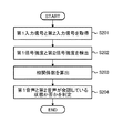
図1は、第1の実施形態による音声処理装置1の機能ブロック図である。音声処理装置1は、取得部2、検出部3、算出部4、判定部5を有する。図2は、音声処理装置1の音声処理のフローチャートである。実施例1においては、図2に示す音声処理装置1による音声処理のフローを、図1に示す音声処理装置1の機能ブロック図の各機能の説明に対応付けて説明する。
(Example 1)
FIG. 1 is a functional block diagram of an
図1の取得部2は、例えば、ワイヤードロジックによるハードウェア回路である。また、取得部2は、音声処理装置1で実行されるコンピュータプログラムにより実現される機能モジュールであっても良い。取得部2は、入力音声の一例となる第1ユーザの第1音声と第2ユーザの第2音声を、例えば、外部装置を介して取得する。なお、当該処理は、図2に示すフローチャートのステップS201に対応する。取得部2は、第1音声が含まれる第1入力信号と第2音声が含まれる第2入力信号の取得方法として、例えば、特開2008−134557号公報に記載の方法を用いることが出来る。ここで、第1ユーザと第2ユーザは、図示しないマイクロフォン(上述の外部装置に相当)をそれぞれ装着しているものとする。第1音声は、例えば、第1ユーザの会話の相手となるユーザ(第2ユーザまたは第2ユーザ以外のユーザ)に対して発話する音声を示す第1ユーザの音声である。また、第2音声は、例えば、第2ユーザの会話の相手となるユーザ(第1ユーザまたは第1ユーザ以外のユーザ)に対して発話する音声を示す第2ユーザの音声である。また、第1音声と第2音声は、例えば、日本語であるが、英語等の他の言語であっても良い。換言すると、実施例1における音声処理においては、言語依存は存在しない。なお、実施例1においては、説明の便宜上、取得部2は第1ユーザの第1音声が含まれる第1入力信号と第2ユーザの第2音声が含まれる第2入力信号を取得するものとして説明するが、取得部2は第1ユーザまたは第2ユーザ以外の第xユーザ(xは、例えば、音声処理装置1を使用するユーザ数)の第x音声が含まれる第x入力信号を取得しても良い。取得部2は取得した第1音声と第2音声を検出部3に出力する。
The
検出部3は、例えば、ワイヤードロジックによるハードウェア回路である。また、検出部3は、音声処理装置1で実行されるコンピュータプログラムにより実現される機能モジュールであっても良い。検出部3は、第1入力信号と第2入力信号を取得部2から受け取る。検出部3は、例えば、第1入力信号または第2入力信号に含まれる複数のフレームから、第1信号強度または第2信号強度を検出する。当該処理は、図2に示すフローチャートのステップS202に対応する。具体的には、検出部3は、第1入力信号に含まれる複数のフレーム毎の信号強度を示す第1信号強度を検出する。また、検出部3は、第2音声に含まれる複数のフレーム毎の信号強度を示す第2信号強度を検出する。なお、第1信号強度または第2信号強度は、例えば、第1音声または第2音声のパワーまたは信号対雑音比であれば良いが、当該パワーと信号対雑音比に限定されるものではない。
The
ここで、検出部3による第1入力信号または第2入力信号のパワーまたは信号対雑音比の検出処理の詳細について説明する。なお、説明の便宜上、第1音声のパワーを第1パワー、第1音声の信号対雑音比を第1信号対雑音比と称し、第2音声のパワーを第2パワー、第2音声の信号対雑音比を第2信号対雑音比と称するものとする。なお、第2パワーの検出方法は、第1パワーの検出方法と同様の手法を用いることができ、第2信号対雑音比の検出方法は、第1信号対雑音比の検出方法と同様の手法を用いることができる。この為、実施例1においては、検出部3による第1パワーと第1信号対雑音比の検出処理の詳細について説明する。
Here, details of the detection processing of the power of the first input signal or the second input signal or the signal-to-noise ratio by the
図3は、一つの実施形態による検出部3の機能ブロック図である。検出部3は、パワー算出部10、雑音推定部11、信号対雑音比算出部12を有する。なお、検出部3は、パワー算出部10、雑音推定部11、信号対雑音比算出部12を必ずしも有する必要はなく、各部が有する機能を、一つのまたは複数のワイヤードロジックによるハードウェア回路で実現させても良い。また、検出部3に含まれる各部が有する機能をワイヤードロジックによるハードウェア回路に代えて、音声処理装置1で実行されるコンピュータプログラムにより実現される機能モジュールで実現させても良い。
FIG. 3 is a functional block diagram of the
(検出部3によるパワー算出方法)
図3において、第1入力信号がパワー算出部10に入力される。なお、パワー算出部10は、図示しないバッファまたはキャッシュを有しても良い。パワー算出部10は、第1入力信号に含まれる各フレームの音量を算出し、当該音量を雑音推定部11と信号対雑音比算出部12へ出力する。なお、第1入力信号に含まれる各フレーム長は、160サンプル(8kHzサンプリングで20msecに相当)である。第1音声信号の信号強度の一例となる第1パワーP1(t)は、次式の通り、第1信号s1(t)のフレーム内の振幅二乗和に対して対数変換することで、算出することが出来る。
(数1)

上述の(数1)において、tはフレーム番号を示し、Lはフレーム長を示す。フレーム長Lは、上述の通り、例えば160サンプル(8kHzサンプリングで20msecに相当)である。
(Method of calculating power by detection unit 3)
In FIG. 3, a first input signal is input to a
(Equation 1)
In the above (Equation 1), t indicates a frame number, and L indicates a frame length. As described above, the frame length L is, for example, 160 samples (corresponding to 20 msec with 8 kHz sampling).
(検出部3による信号対雑音比算出方法)
雑音推定部11は、各フレームの第1パワーP1(t)をパワー算出部10から受け取る。雑音推定部11は、各フレームにおける雑音を推定して、雑音推定結果を信号対雑音比算出部12へ出力する。ここで、雑音推定部11による各フレームの雑音推定は、例えば、以下の雑音推定方法を用いることが出来る。
(Method of calculating signal-to-noise ratio by detection unit 3)
The noise estimation unit 11 receives the first power P1 (t) of each frame from the
(雑音推定方法)
雑音推定部11は、第1入力信号のパワーP1(t)と、1フレーム過去の第1雑音電力N1(t−1)の差に応じて第1雑音電力を次式に基づいて更新する。雑音推定部11は、第1音声信号のパワーP1(t)と、1フレーム過去の第1雑音電力N1(t−1)の差が所定閾値(例えば、5dB)を下回る場合は雑音パワーを音声信号が雑音であると推定し、第1雑音電力N1(t)を更新する。一方で、雑音推定部11は、第1入力信号のパワーP1(t)と、1フレーム過去の第1雑音電力N1(t−1)の差が所定閾値以上の場合は第1雑音電力を次式に基づいて更新しない。
(数2)
![]()
上述の(数2)において、TH_Pは雑音区間と判定するための判定閾値であり、例えば5dBであれば良い。また、COFは忘却係数であり、例えば0.05であれば良い。雑音推定部11は雑音推定結果となる各フレームの第1雑音電力(t)を受け取る。
(Noise estimation method)
The noise estimating unit 11 updates the first noise power based on the difference between the power P1 (t) of the first input signal and the first noise power N1 (t-1) one frame earlier based on the following equation. If the difference between the power P1 (t) of the first audio signal and the first noise power N1 (t-1) of one frame past is less than a predetermined threshold (for example, 5 dB), the noise estimating unit 11 outputs the noise power. It is estimated that the signal is noise, and the first noise power N1 (t) is updated. On the other hand, when the difference between the power P1 (t) of the first input signal and the first noise power N1 (t−1) of one frame past is equal to or greater than a predetermined threshold, the noise estimation unit 11 sets the first noise power to the next. Do not update based on formula.
(Equation 2)
![]()
In the above (Equation 2), TH_P is a determination threshold for determining a noise section, and may be, for example, 5 dB. COF is a forgetting factor, and may be, for example, 0.05. The noise estimating unit 11 receives the first noise power (t) of each frame as a noise estimation result.
図3において、信号対雑音比算出部12は、パワー算出部10から各フレームの第1パワーP1(t)を受け取り、雑音推定部11から雑音推定結果となる各フレームの第1雑音電力N1(t)を受け取る。なお、信号対雑音比算出部12は、図示しないキャッシュまたはメモリを有しており、過去Lフレーム分の第1パワーP1(t)、第1雑音電力N1(t)を保持することができる。信号対雑音比算出部12は、次式を用いて、第1信号対雑音比SNR1(t)を算出する。
(数3)
![]()
(Equation 3)
![]()
図4は、実施例1に係る検出部3の検出処理のフローチャートである。検出部3は、第1入力信号と第2入力信号を取得部2から受け取る(ステップS401)。次に、検出部3は、第1入力信号の第1パワーと第2入力信号の第2パワーを上述の(数1)に基づいて検出する(ステップS402)。次に、第1音声の第1雑音電力と第2音声の第2雑音電力を上述の(数2)に基づいて検出する(ステップS403)。そして、検出部3は、第1パワーと第2パワーを第1信号強度と第2信号強度として選択するか否かを決定する(ステップS404)。例えば、第1雑音電力と第2雑音電力がそれぞれ所定の閾値を下回る場合に、第1パワーと第2パワーを第1信号強度と第2信号強度として選択する。検出部3は、第1パワーと第2パワーを第1信号強度と第2信号強度として選択することを決定した場合(ステップS404−Yes)は、第1パワーと第2パワーを第1信号強度と第2信号強度として算出部4に出力する(ステップS407)ことで、図4のフローチャートに示す検出処理を終了する。一方、検出部3は、第1パワーと第2パワーを第1信号強度と第2信号強度として選択することを決定しない場合(ステップS404−No)は、検出部3は、第1音声の第1信号対雑音比と第2音声の第2信号対雑音比を上述の(数3)に基づいて検出する(ステップS405)。次に、検出部3は、第1信号対雑音比と第2信号対雑音比を、第1信号強度または第2信号強度として算出部4に出力する(ステップS406)ことで、図4のフローチャートに示す検出処理を終了する。
FIG. 4 is a flowchart of the detection process of the
図5(a)は、検出部3による第1信号強度の第1検出結果を示す図である。図5(a)の横軸は時間を示し、縦軸は第1信号強度の一例となる第1パワーを示している。図5(b)は、検出部3による第2信号強度と第2信号強度の第2検出結果を示す図である。図5(b)の横軸は時間を示し、縦軸は第2信号強度の一例となる第2パワーを示している。なお、図5(a)と図5(b)の縦軸のパワーと横軸の時間は同一スケールである。検出部3は検出した第1信号強度と第2信号強度を算出部4に出力する。
FIG. 5A is a diagram illustrating a first detection result of the first signal strength by the
図1において、算出部4は、例えば、ワイヤードロジックによるハードウェア回路である。また、算出部4は、音声処理装置1で実行されるコンピュータプログラムにより実現される機能モジュールであっても良い。算出部4は、第1信号強度と第2信号強度を検出部3から受け取る。算出部4は、第1信号強度と第2信号強度の時系列に対する相関係数を算出する。なお、当該処理は、図2に示すフローチャートのステップS203に対応する。具体的には、算出部4は、次式に基づいて、第1信号強度と第2信号強度の時系列に対する相関係数corr.を算出する。
(数4)
(Equation 4)
ここで、算出部4が、第1信号強度と第2信号強度の時系列に対する相関係数を算出する技術的意義について説明する。先ず、初めに本発明者らが検討した比較例について説明する。なお、当該比較例は公知技術ではなく、本発明者らにより新たに検証された事項であることを付言する。 Here, the technical significance of calculating the correlation coefficient of the first signal strength and the second signal strength with respect to the time series will be described. First, a comparative example studied first by the present inventors will be described. It is to be noted that the comparative example is not a known technique but is a matter newly verified by the present inventors.
(比較例)
複数の話者の音声が個別に録音された音声データに対し、会話が行われている話者に対応した音声データの組み合せを、2つの音声データの「発話時間の比率」に基づいて判定する方法を比較例として考える。図6(a)は、検出部3による第1信号強度の参考検出結果を示す図である。図6(a)の横軸は時間を示し、縦軸は第1信号強度の一例となる第1パワーを示している。図6(b)は、検出部3による第2信号強度と第2信号強度の参考検出結果を示す図である。図6(b)の横軸は時間を示し、縦軸は第2信号強度の一例となる第2パワーを示している。なお、図6(a)と図6(b)の縦軸のパワーと横軸の時間は同一スケールである。ここで、任意の閾値(例えば、10dB)以上の信号強度を満たす時間を発話時間と定義し、図6(a)と図6(b)の場合における発話時間の比率(第1音声の発話時間/第2音声の発話時間)を算出すると、発話時間の比率は1.1となる。また、図5(a)と図5(b)の場合における発話時間の比率を、図6(a)と図6(b)の場合と同様に算出すると発話時間の比率は1.1となる。
(Comparative example)
With respect to voice data in which voices of a plurality of speakers are individually recorded, a combination of voice data corresponding to a speaker having a conversation is determined based on a “ratio of utterance time” of two voice data. The method is considered as a comparative example. FIG. 6A is a diagram illustrating a reference detection result of the first signal intensity by the
ここで、自然な会話においては、話者同士が交互に発話を行うことでコミュニケーションを図る為、一方の話者の発話量が多い時間帯は、他方の話者の発話量が少ない(相手の発話に耳を傾ける)ことが想定される。ここで、図5(a)、図5(b)と図6(a)、図6(b)の組み合せを客観的に比較した場合、一方の話者の発話量が多い時間帯に、他方の話者の発話量が少ないのは、図5(a)、図5(b)の組み合せであることが理解できる。図6(a)、図6(b)の組み合せは、一方の話者の発話量が多い時間帯に、他方の話者の発話量も多くなっている為、一般的には第1ユーザと第2ユーザは、それぞれお互いに別のユーザと会話していることが想定される。 Here, in a natural conversation, since speakers communicate with each other by uttering alternately, during a time period in which one speaker has a large amount of speech, the other speaker has a small amount of speech (the other party's speech amount is small). Listening to the utterance). Here, when the combinations of FIGS. 5A and 5B and FIGS. 6A and 6B are objectively compared, when one speaker has a large utterance amount, It can be understood that the reason that the speaker's utterance amount is small is the combination of FIGS. 5 (a) and 5 (b). In the combination of FIGS. 6A and 6B, the amount of utterance of one speaker is large during the time period when the amount of utterance of one speaker is large. It is assumed that the second users are each having a conversation with another user.
図7は、発話時間の比率の分布図である。図7においては、20話者の音声データの組み合せとなる190組において、実際に会話をしている状態の10組の音声データの組み合せと、会話を行っていない状態の180組の音声データの組み合せの発話時間の比率の分布図を示している。図7の発話時間の比率の分布図から理解できる通り、会話をしている音声データの組み合せの発話時間の比率と、会話を行っていない音声データの組み合せの発話時間の比率は同等程度であることが確認された。この為、複数の話者の音声が個別に録音された音声データから会話が行われている話者に対応した音声データの組み合せを、比較例に示した2つの音声データの「発話時間の比率」に基づいて判定することは難しいことが、本発明者らの検証により明らかになった。 FIG. 7 is a distribution diagram of the utterance time ratio. In FIG. 7, in 190 combinations that are combinations of audio data of 20 speakers, a combination of 10 sets of audio data in a state where a conversation is actually being performed and a combination of 180 sets of audio data in a state where a conversation is not being performed. 5 shows a distribution diagram of the ratio of the speech time of the combination. As can be understood from the distribution diagram of the speech time ratios in FIG. 7, the speech time ratio of the combination of speech data having a conversation and the speech time ratio of the combination of speech data not having a conversation are almost the same. It was confirmed that. For this reason, the combination of the voice data corresponding to the speaker having the conversation from the voice data in which the voices of a plurality of speakers are individually recorded is referred to as the “ratio of utterance time” of the two voice data shown in the comparative example. It has been clarified by the present inventors that it is difficult to make a determination based on "."
一方、自然な会話においては、話者同士が交互に発話を行うことでコミュニケーションを図る為、図5(a)、図5(b)に示される通り、一方の話者の発話量が多い時間帯は、他方の話者の発話量が少ないことが想定される。ここで、図5(a)、図5(b)における、第1信号強度と第2信号強度の時系列に対する相関関係に着目すると、一方の変数(例えば、第1信号強度)が増大するほど、他方の変数(例えば、第2信号強度)が減少する「負の相関」の関係を有していることが理解できる。 On the other hand, in a natural conversation, since speakers communicate alternately with each other to communicate with each other, as shown in FIG. 5A and FIG. In the band, it is assumed that the utterance amount of the other speaker is small. Here, focusing on the correlation of the first signal strength and the second signal strength with respect to the time series in FIGS. 5A and 5B, as one of the variables (for example, the first signal strength) increases. It can be understood that the other variable (eg, the second signal strength) has a “negative correlation” relationship that decreases.
この為、本実施例1の算出部4が、当該負の相関の強さを示す相関係数を算出することで、後述する判定部5が、当該相関係数に基づいて、第1音声と第2音声が会話している状態か否かを判定することができる。図8は、第1音声と第2音声が会話している状態における第1信号強度の時系列と第2信号強度の時系列との相関関係を示す図である。図8に示す通り、第1音声と第2音声が会話している状態においては、相関関係は負の相関(負の相関係数)を有することが理解できる。
For this reason, the
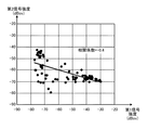
図9は、第1信号強度の時系列と第2信号強度の時系列との相関係数の分布図である。図9においては、第1ユーザと第2ユーザの音声データを11組(計31分)用い、会話している区間と、会話していない区間(別の話者と会話している区間)を評価者が主観評価によって判定した上で、第1信号強度と第2信号強度の時系列に対する相関係数をそれぞれ算出した。図9から理解できる通り、会話している区間と会話していない区間で相関係数の範囲が明確に異なっていることが確認された。図9の実験結果より、任意の閾値である第1閾値を例えば、−0.4(一般的に相関の強さが中程度の値)と規定し、当該第1閾値と第1信号強度と第2信号強度の時系列に対する相関係数を用いることで、第1音声と第2音声が会話している状態か否(会話していない状態)かを判定することができる。 FIG. 9 is a distribution diagram of the correlation coefficient between the time series of the first signal strength and the time series of the second signal strength. In FIG. 9, 11 sets of voice data of the first user and the second user (a total of 31 minutes) are used, and a section in which the user is talking and a section in which the user is not talking (a section where the user is talking with another speaker) are set. After the evaluator made the judgment by the subjective evaluation, the correlation coefficients of the first signal intensity and the second signal intensity with respect to the time series were calculated. As can be understood from FIG. 9, it was confirmed that the range of the correlation coefficient was clearly different between the talking section and the talking section. From the experimental results in FIG. 9, the first threshold value, which is an arbitrary threshold value, is defined as, for example, −0.4 (generally a value having a moderate correlation strength). By using the correlation coefficient with respect to the time series of the second signal strength, it is possible to determine whether or not the first voice and the second voice are in a state of talking (non-talking state).
図1において、判定部5は、例えば、ワイヤードロジックによるハードウェア回路である。また、判定部5は、音声処理装置1で実行されるコンピュータプログラムにより実現される機能モジュールであっても良い。判定部5は、算出部4が算出した第1信号強度の時系列と第2信号強度の時系列との相関係数を算出部4から受け取る。判定部5は、相関係数に基づいて第1音声と第2音声が会話している状態か否かを判定する。なお、当該処理は、図2に示すフローチャートのステップS204に対応する。判定部5は、相関係数が負であり、相関係数が上述の第1閾値未満(例えば、−0.4>相関係数>=−1.0)の場合に第1音声と第2音声が会話している状態であると判定する。換言すると、判定部5は、相関係数が第1閾値以上(例えば、−0.4<=相関係数<=+1.0)の場合に、第1音声と第2音声が会話していない状態であると判定しても良い。判定部5は、判定結果を任意の外部装置(例えば、図示しないコンピュータ)に出力する。
In FIG. 1, the
判定部5は、必要に応じて、第1音声と第2音声が会話している状態と判定した相関係数の算出に用いられた、上述の(数4)におけるTe−Tsの区間長を算出部4から受け取り、当該区間長を、第1ユーザと第2ユーザが会話した区間(時間)として外部装置に出力することもできる。または、判定部5は、必要に応じて、第1音声と第2音声が会話している状態と判定した相関係数の算出に用いられた、上述の(数4)における始点時刻のTsと、終点時刻のTeを算出部4から受け取り、当該Tsを第1ユーザと第2ユーザの会話の始点時刻、Teを第1ユーザと第2ユーザの会話の終点時刻として外部装置に出力することもできる。
The
図10は、実施例1に係る算出部4の算出処理と判定部5の判定処理のフローチャートである。算出部4は、第1信号強度と第2信号強度を検出部3から受け取る(ステップS1001)。次に、算出部4は、第1信号強度と第2信号強度の時系列に対する相関係数を(数4)に基づいて算出する(ステップS1002)。算出部4は、算出した相関係数を判定部5に出力する(ステップS1003)ことで、図10のフローチャートに示す算出部4の算出処理を終了する。
FIG. 10 is a flowchart of the calculation process of the
判定部5は、算出部4が算出した相関係数を算出部4から受け取る(ステップS1004)。判定部5は、相関係数が上述の第1閾値未満か否かを判定する(ステップS1005)。相関係数が上述の第1閾値未満の場合(ステップS1005−Yes)、判定部5は、第1音声と第2音声が会話している状態として判定し(ステップS1006)、その判定結果を任意の外部装置に出力する(ステップS1008)ことで、図10のフローチャートに示す判定部5の判定処理を終了する。一方、相関係数が上述の第1閾値以上の場合(ステップS1005−No)、判定部5は、第1音声と第2音声が会話していない状態として判定し(ステップS1007)、その判定結果を任意の外部装置に出力する(ステップS1008)ことで、図10のフローチャートに示す判定部5の判定処理を終了する。
The
図11は、実施例1と上述の比較例による複数の話者の音声が個別に録音された音声データから、会話をしている音声データの組み合せの判定性能を示す図である。図11は、20話者の音声データの組み合せ計190組(会話している音声データの組み合せ10組、会話していない音声データの組み合せ180組の合計)において、会話している音声データの検出率(会話している音声を検出した割合)と、当該検出した会話している音声データの正解率(検出した音声が会話している状態である割合)を示している。なお、比較例においては、検出率が100%となるように発話時間比が1.2以下の音声データの組み合せを会話しているデータとして判定した。図11から理解できる通り、実施例1によれば、比較例に対して正解率が大幅に向上していることが確認された。実施例1における音声処理装置1に依れば、会話において一方が発話している場合、他方は発話しない特徴を利用し、異なるユーザ同士の音声信号強度の時系列に対する相関係数が負であり、かつ相関係数が上述の第1閾値未満の場合にユーザ同士が会話していると判定することが可能となる。換言すれば、実施例1における音声処理装置1は、複数の話者の音声が個別に録音された音声データから、会話が行われている話者に対応した音声データの組み合せを、高い精度で判定することが可能となる。
FIG. 11 is a diagram illustrating a determination performance of a combination of voice data having a conversation from voice data in which voices of a plurality of speakers are individually recorded according to the first embodiment and the comparative example. FIG. 11 shows detection of speech data in conversation in a total of 190 combinations of speech data of 20 speakers (10 combinations of speech data in conversation and 180 combinations of speech data in non-conversation). A rate (a rate at which a conversational voice is detected) and a correct answer rate of the detected conversational speech data (a rate at which the detected speech is in a conversation state) are shown. In the comparative example, a combination of voice data having an utterance time ratio of 1.2 or less was determined as conversational data so that the detection rate was 100%. As can be understood from FIG. 11, according to Example 1, it was confirmed that the accuracy rate was significantly improved as compared with the comparative example. According to the
(実施例2)
図1の検出部3は、実施例1の検出処理に加えて、第1信号強度と第2信号強度の時系列に対する大小関係を検出し、当該大小関係が反転する反転回数が第4閾値以上(例えば、第4閾値=6回)となる相関係数算出区間を検出しても良い。また、図1の算出部4は、実施例1の算出処理に加えて、実施例2に係る検出部3が検出する相関係数算出区間における相関係数を算出しても良い。以下、実施例2に係る音声処理装置1の音声処理の詳細について説明する。
(Example 2)
In addition to the detection processing of the first embodiment, the
検出部3は、第1信号強度と第2信号強度の時系列に対する大小関係を検出する。具体的には、検出部3は、第1信号強度と第2信号強度(例えば、第1パワーと第2パワー)の差が所定の第5閾値(例えば、パワー差=+20dB)以上となる第1状態と、第1信号強度と第2信号強度(例えば、第1パワーと第2パワー)の差が所定の第6閾値(例えば、パワー差=−20dB)以下となる第2状態を検出する。検出部3は、第1状態から第2状態へ遷移した場合、または、第2状態から第1状態に遷移した場合を話者交代点(第1信号強度と第2信号強度の時系列に対する大小関係が反転する点と称しても良い)として検出する。検出部3が、話者交代点が所定の第4閾値(例えば、第4閾値=6回)となる相関係数算出区間を検出する。図12は、相関係数算出区間の概念図である。図12の横軸は第1音声または第2音声の時系列であり、縦軸は、第1信号強度と第2信号強度の差の一例となるパワー差である。なお、図12のパワー差は、図5(a)と図5(b)のパワー差を示している。検出部3は、話者交代点が第4閾値以上を満たす区間を相関係数算出区間として検出する。検出部3は、検出した相関係数算出区間を算出部4に出力する。
The detecting
算出部4は、検出部3が検出した相関係数算出区間を検出部3から受け取る。算出部4は、相関係数算出区間における第1信号強度と第2信号強度の時系列に対する相関係数を実施例1と同様の手法を用いて算出する。算出部4は、上述の(数4)のTsを相関係数算出区間の始点時刻とし、Teを相関係数算出区間の終点時刻とし、Te−Tsで表現される相関係数算出区間における第1信号強度と第2信号強度の時系列に対する相関係数を算出すれば良い。なお、算出部4は、検出部3から複数の相関係数算出区間を受け取っている場合は、複数の相関係数算出区間毎に相関係数を算出すれば良い。算出部4は、算出した相関係数を判定部5に出力し、判定部5は実施例1と同様の方法で判定処理を行えば良い。なお、判定部5は、複数の相関係数を算出部4から受け取っている場合は、実施例1と同様の方法で相関係数毎に判定処理を行えば良い。
The
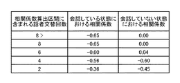
ここで、実施例2における技術的意義について説明する。図13は、相関係数算出区間に含まれる話者交替回数と、会話している状態または会話していない状態における当該相関係数算出区間に基づいて算出した相関係数の関係を示す図である。図13から理解できる通り、話者交代回数が多い区間(例えば、上述の第4閾値となる6回)の場合、会話している音声データの組み合せの相関係数と、会話していない音声データの組み合せの差(有意差)が現れる。この為、実施例2における音声処理装置1においては、話者交代回数が所定の第4閾値以上となる相関係数算出区間で相関係数を算出することで、高い精度で複数の話者の音声が個別に録音された音声データから、会話が行われている話者に対応した音声データの組み合せを、高い精度で判定することが可能となる。なお、実施例2における音声処理装置1は、実施例1に記載した音声処理を任意に組み合せることができる。
Here, the technical significance of the second embodiment will be described. FIG. 13 is a diagram showing the relationship between the number of speaker changes included in the correlation coefficient calculation section and the correlation coefficient calculated based on the correlation coefficient calculation section in a talking state or a non-talking state. is there. As can be understood from FIG. 13, in a section where the number of times of speaker change is large (for example, the above-described fourth threshold value of 6), the correlation coefficient of the combination of speech data in conversation and the speech data in non-conversation (Significant difference) appears. For this reason, in the
(実施例3)
図1の算出部4は、実施例1または実施例2の算出処理に加えて、第1信号強度の第1位相または、第2信号強度の第2位相を所定の範囲で変化させて複数の相関係数を算出しても良い。また、図1の判定部5は、算出部4が第1位相または第2位相を所定の範囲で変化させて算出した複数の相関係数の中で、最小値を満たす相関係数に基づいて、第1音声と第2音声が会話している状態か否かを判定しても良い。以下、実施例3に係る音声処理装置1の音声処理の詳細について説明する。
(Example 3)
The
算出部4は、第1信号強度の第1位相または、第2信号強度の第2位相を所定の範囲で変化させて複数の相関係数を算出する。実施例3においては、第1位相を所定の範囲で変化させた場合について説明するが、第2位相を所定の範囲で変化させる場合も第1位相の場合と同様に算出することが出来る為、第2位相に関する詳細な説明は省略する。算出部4は、次式に基づいて、第1信号強度(例えば、第1パワーP1)の位相を変化させた場合の第1信号強度P1(t)と第2信号強度P2(t)の複数の相関係数から、最小値の相関係数を満たす位相dminを次式に基づいて算出する。
(数5)
上述の(数5)においてdは位相の変更量(サンプル)を示し、Dmaxは位相変更の最大値を示す。Dmaxは、例えば80000サンプル(10秒に相当)とすれば良い。算出部4は、第1強度の位相を所定の範囲となるdmin変化(シフトと称しても良い)させた信号P1’tを次式に基づいて算出する。
(数6)
P1’(t) = P1(t+dmin)
判定部5は、複数の相関係数のうち最小値の満たす相関係数に基づいて、第1音声と第2音声が会話している状態か否かを実施例1と同様の判定方法を用いて判定する。
The
(Equation 5)
In the above (Equation 5), d indicates a phase change amount (sample), and Dmax indicates a maximum value of the phase change. Dmax may be, for example, 80000 samples (corresponding to 10 seconds). The
(Equation 6)
P1 ′ (t) = P1 (t + dmin)
The
実施例3における音声処理装置1によれば、例えば、取得部2が取得する第1入力信号と第2入力信号のそれぞれにおいて、録音のタイミングが同期していない場合(例えば、第1ユーザと第2ユーザがそれぞれ装着しているマイクロフォンの音声処理の内部処理の差異や、設定時刻のずれ等に起因して録音のタイミングが同期していない場合)においても、相関係数を算出する時点において、位相を調整することによって、会話している音声データの組み合せの判定精度を向上させることが可能となる。なお、実施例3における音声処理装置1は、実施例1または実施例2に記載した音声処理を任意に組み合せることができる。
According to the
(実施例4)
図1の検出部3は、実施例1ないし実施例3の検出処理に加え、第1入力信号に含まれる第1発話区間を第1信号強度に基づいて検出し、第2入力信号に含まれる第2発話区間を第2信号強度に基づいて検出し、第1発話区間と第2発話区間が重複する重複発話区間を検出しても良い。また、図1の算出部4は、実施例1ないし実施例3の算出処理に加え、当該重複発話区間が第2閾値未満の第1信号強度と第2信号強度を、相関係数の算出に用いない算出処理を行っても良い。また、検出部3は、第1入力信号に含まれる第1無音区間を第1信号強度に基づいて検出し、第2入力信号に含まれる第2無音区間を第2信号強度に基づいて検出し、第1無音区間と第2無音区間が重複する重複無音区間を検出しても良い。算出部4は、当該重複無音区間が第3閾値未満の第1信号強度と第2信号強度を、相関係数の算出に用いない算出処理を行っても良い。以下、実施例4に係る音声処理装置1の音声処理の詳細について説明する。
(Example 4)
The
検出部3は、例えば、第1信号のフレーム単位で、第1信号強度が所定の閾値(例えば、10dB(但し、第1信号強度として第1パワーを用いる場合))以上か否かを判定する。検出部3は、第1信号強度が当該閾値以上を満たすフレームを第1発話区間として判定する。また、検出部3は、第1信号強度が当該閾値未満を満たすフレームを第1無音区間として判定する。検出部3は、次式に基づいて、フレーム単位で当該フレームが第1発話区間か第1無音区間(非発話区間と称しても良い)を判定し、判定結果v1(t)を検出する。
(数7)
上述の(数7)において、tはフレーム番号を示す。なお、1フレームの長さは、例えば、20msである。また、上述の(数7)においては、tフレーム目の第1音声が発話区間と判定された場合はv1(t)=1が代入され、tフレーム目の第1音声が無音区間と判定された場合はv1(t)=0と代入されることを意味する。検出部3は、v1(t)=1を連続して満たすフレーム区間を第1発話区間として出力する。なお、検出部3は、第2音声に関する判定結果v2(t)をv1(t)と同様の手法を用いて算出し、第2発話区間または第2無音区間を検出する。
The
(Equation 7)
In the above (Equation 7), t indicates a frame number. The length of one frame is, for example, 20 ms. In the above (Equation 7), if the first voice of the t-th frame is determined to be a speech section, v1 (t) = 1 is substituted, and the first voice of the t-th frame is determined to be a silent section. Means that v1 (t) = 0 is substituted. The detecting
次に、検出部3は、第1発話区間と第2発話区間が重複する重複発話区間を検出する。当該重複発話区間は、例えば、ある任意の同一の時刻において、第1ユーザと第2ユーザが互いに発話している区間と定義することが出来る。なお、検出部3は、具体的には、次式に基づいて重複発話区間TO(t)を検出することが出来る。
(数8)
上述の(数8)は、第1ユーザの第1音声と第2ユーザの第2音声の何れかが無音区間と判定されるフレームに対しては重複時間を0(重複区間の発現無し)と規定し、第1ユーザの第1音声と第2ユーザの第2音声の双方が発話区間と判定されるフレームに対しては直前のフレームまでの重複時間に1フレーム加算することで、重複が連続するフレーム数(重複区間)を算出することを意味する。検出部4は、規定した重複発話区間を算出部5に出力する。なお、重複発話区間には、区間の長さの情報が含まれているものとする。重複発話区間の長さLOは、例えば、次式に基づいて算出することができる。
(数9)
LO=TO_e(i)−TO_s(i)
なお、上述の(数9)において、TO_s(i)は、重複発話区間の始点(開始フレーム)であり、TO_e(i)は、重複発話区間の終点(終了フレーム)である。
Next, the detecting
(Equation 8)
In the above (Equation 8), the overlapping time is set to 0 (no occurrence of the overlapping section) for a frame in which either the first voice of the first user or the second voice of the second user is determined to be a silent section. It is prescribed that, for a frame in which both the first voice of the first user and the second voice of the second user are determined to be speech sections, one frame is added to the overlapping time up to the immediately preceding frame so that the overlap is continuous. Means to calculate the number of frames to be performed (overlapping section). The detecting
(Equation 9)
LO = TO_e (i) −TO_s (i)
In the above (Equation 9), TO_s (i) is the start point (start frame) of the overlap utterance section, and TO_e (i) is the end point (end frame) of the overlap utterance section.
次に、検出部3は、第1無音区間と第2無音区間が重複する重複無音区間を検出する。当該重複無音区間は、例えば、ある任意の同一の時刻において、第1ユーザと第2ユーザが互いに発話していない区間と定義することが出来る。なお、検出部3は、具体的には、次式に基づいて重複無音区間TE(t)を検出することが出来る。
(数10)
![]()
上述の(数10)は、第1ユーザの第1音声と第2ユーザの第2音声の何れかまたは双方が発話区間と判定されるフレームに対しては重複時間を0(重複区間の発現無し)と規定し、第1ユーザの第1音声と第2ユーザの第2音声の双方が無音区間と判定されるフレームに対しては直前のフレームまでの重複時間に1フレーム加算することで、重複が連続するフレーム数(重複区間)を算出することを意味する。検出部4は、規定した重複無音区間を算出部4に出力する。なお、重複無音区間には、区間の長さの情報が含まれているものとする。重複無音区間の長さLSは、例えば、次式に基づいて算出することができる。
(数11)
LS=TS_e(i)−TS_s(i)
なお、上述の(数11)において、TS_s(i)は、重複無音区間の始点(開始フレーム)であり、TS_e(i)は、重複無音区間の終点(終了フレーム)である。
Next, the detecting
(Equation 10)
![]()
In the above (Equation 10), the overlap time is set to 0 (there is no occurrence of the overlap section) for a frame in which one or both of the first speech of the first user and the second speech of the second user is determined to be the speech section. ) Is defined, and for a frame in which both the first voice of the first user and the second voice of the second user are determined to be silent sections, one frame is added to the overlapping time up to the immediately preceding frame, whereby the overlap is obtained. Means calculating the number of consecutive frames (overlapping section). The
(Equation 11)
LS = TS_e (i) −TS_s (i)
In the above (Equation 11), TS_s (i) is the start point (start frame) of the overlapping silent section, and TS_e (i) is the end point (ending frame) of the overlapping silent section.
(重複発話区間に対する処理)
算出部4は、重複発話区間の長さが所定の第2閾値未満(例えば、第2閾値=1秒(50フレームに相当))となる第1信号強度と第2信号強度を相関係数の算出に用いない算出処理を行うことができる。換言すると、算出部4は、重複発話区間が第2閾値未満となる第1信号強度と第2信号強度以外の相関係数を用いて相関係数の算出処理を実施例1と同様の方法で行う。ここで、第2閾値未満の重複発話区間の長さは、例えば、「はい」、「いいえ」、「うんうん」、「本当?」、「そうです」等の一般的に相槌の長さに相当する。相槌は、実際に会話している状態において発生するものである。一方が発話している時間帯に他方も発話する(相槌を打つ)場合も存在する為、重複発話区間の長さが第2閾値未満となる第1信号強度と第2信号強度を相関係数の算出に用いないことで、相槌の影響を排除することが可能となる。なお、重複発話区間の長さが第2閾値未満となる第1信号強度と第2信号強度を相関係数の算出に用いた場合、互いに会話している状態であるにも係らず、第1信号強度と第2信号強度が、互いにある程度の強さの信号強度を有している為、相関係数は会話していない状態を示す正の値に近づくことになる。
(Process for duplicate utterance section)
The
(重複無音区間に対する処理)
算出部4は、重複無音区間の長さが所定の第3閾値未満(例えば、第3閾値=10秒(500フレームに相当))となる第1信号強度と第2信号強度を相関係数の算出に用いない算出処理を行うことができる。換言すると、算出部4は、重複発話区間が第3閾値未満となる第1信号強度と第2信号強度以外の相関係数を用いて相関係数の算出処理を実施例1と同様の方法で行う。ここで、第3閾値未満の重複無音区間の長さは、会話している状態で発生することが想定される無音区間である。実際に会話している場合においては、例えば、双方が発話する内容を考えることより、無音区間が重複する場合も想定される。この為、算出部4が、重複発話区間の長さが第3閾値未満となる第1信号強度と第2信号強度を相関係数の算出に用いないことで、上述の影響を排除することが可能となる。
(Processing for overlapping silent sections)
The
図15は、実施例4に係る検出部3の検出処理と算出部4の算出処理のフローチャートである。検出部3は、第1音声の第1発話区間と第1無音区間を、上述の(数7)に基づいて検出する(ステップS1501)。次に、検出部3は、第2音声の第2発話区間と第2無音区間を、上述の(数7)に基づいて検出する(ステップS1502)。次に、検出部3は、第1発話区間と第2発話区間から重複発話区間を上述の(数8)に基づいて検出する(ステップS1503)。次に、検出部3は、第1無音区間と第2無音区間から重複無音区間を上述の(数10)に基づいて検出する(ステップS1504)。検出部3は、検出した重複発話区間と重複無音区間を算出部4に出力することで、図15のフローチャートに示す検出処理を終了する。
FIG. 15 is a flowchart of the detection process of the
算出部4は、重複発話区間と重複無音区間を検出部3から受け取り、重複発話区間が上述の第2閾値未満、かつ重複無音区間が上述の第3閾値未満か否かを判定する(ステップS1505)。重複発話区間が上述の第2閾値未満、かつ重複無音区間が上述の第3閾値未満の場合(ステップS1505−Yes)、算出部4は、重複発話区間と重複無音区間を用いないで相関係数を上述の(数4)に基づいて算出し(ステップS1509)、算出した相関係数を判定部5に出力する(ステップS1512)ことで、図15のフローチャートに示す算出処理を終了する。
The calculating
重複発話区間が上述の第2閾値未満、かつ重複無音区間が上述の第3閾値未満ではない場合(ステップS1505−No)、算出部4は、重複発話区間が第2閾値未満、かつ重複無音区間が第3閾値以上か否かを判定する(ステップS1506)。重複発話区間が第2閾値未満、かつ重複無音区間が第3閾値以上の場合(ステップS1506−Yes)、算出部4は、重複発話区間を用いないで相関係数を上述の(数4)に基づいて算出し(ステップS1510)、算出した相関係数を判定部5に出力する(ステップS1512)ことで、図15のフローチャートに示す算出処理を終了する。
When the overlapping utterance section is less than the second threshold value and the overlapping silence section is not less than the third threshold value (step S1505-No), the calculating
重複発話区間が上述の第2閾値未満、かつ重複無音区間が上述の第3閾値以上ではない場合(ステップS1506−No)、算出部4は、重複発話区間が第2閾値以上、かつ重複無音区間が第3閾値未満か否かを判定する(ステップS1507)。重複発話区間が第2閾値以上、かつ重複無音区間が第3閾値未満の場合(ステップS1507−Yes)、算出部4は、重複無音区間を用いないで相関係数を上述の(数4)に基づいて算出し(ステップS1511)、算出した相関係数を判定部5に出力する(ステップS1512)ことで、図15のフローチャートに示す算出処理を終了する。
When the overlapping utterance section is less than the second threshold value and the overlapping silent section is not equal to or greater than the third threshold value (step S1506-No), the calculating
重複発話区間が第2閾値以上、かつ重複無音区間が第3閾値未満ではない場合(ステップS1507−No)、算出部4は、実施例1と同様の方法で、相関係数を上述の(数4)に基づいて算出し(ステップS1508)、算出した相関係数を判定部5に出力する(ステップS1512)ことで、図15のフローチャートに示す算出処理を終了する。
When the overlapping utterance section is not less than the second threshold value and the overlapping silence section is not less than the third threshold value (step S1507-No), the
実施例4においては、説明の便宜上、重複発話区間と重複無音区間に対する双方の処理について説明したが、重複発話区間または重複無音区間の何れか一方のみを処理対象としても良いし、双方を処理対象としても良い。実施例4に係る音声処理装置においては、複数の話者の音声が個別に録音された音声データから、会話が行われている話者に対応した音声データの組み合せを、重複発話区間または重複無音区間を考慮することで、高い精度で判定することが可能となる。なお、実施例4における音声処理装置1は、実施例1ないし実施例3に記載した音声処理を任意に組み合せることができる。
In the fourth embodiment, for the sake of convenience, both processes for the overlapping utterance section and the overlapping silence section have been described. However, only one of the overlapping utterance section and the overlapping silence section may be processed, or both may be processed. It is good. In the voice processing apparatus according to the fourth embodiment, a combination of voice data corresponding to speakers having a conversation is determined from voice data in which voices of a plurality of speakers are individually recorded, by using an overlapping speech section or an overlapping silence. Considering the section makes it possible to determine with high accuracy. The
(実施例5)
図1の取得部2は、第1ユーザの第1音声が含まれる第1入力信号または第2ユーザの第2音声が含まれる第1入力信号のみならず、複数のユーザ(第xユーザと称しても良い)の各音声が含まれる各入力信号(第x入力音声と称しても良い)を取得することが出来る。実施例5においては、複数のユーザの各音声の組み合せにおいて、実際に会話をしている2つの音声データの組み合せを判定する方法について説明する。なお、実施例5は、説明の便宜上、第1ユーザの第1音声ないし第4ユーザの第4音声を取得部2が外部装置を介して取得するものとして説明する。ここで、第1ユーザないし第4ユーザは、図示しないマイクロフォン(上述の外部装置に相当)をそれぞれ装着しているものとする。取得部2は取得した第1音声ないし第4音声を検出部3に出力する。
(Example 5)
The
図1の検出部3は、第1入力音声ないし第4入力音声を取得部3から受け取る。検出部3は、第1信号ないし第4音声の各信号強度(第1信号強度、第2信号強度、第3信号強度、第4信号強度)を、例えば、実施例1に記載した検出方法を用いて検出する。検出部3は、検出した第1信号強度ないし第4信号強度を算出部4に出力する。
The
図1の算出部4は、各信号強度、換言すると第1信号強度ないし第4信号強度を検出部3から受け取る。算出部4は、各信号強度から2つの信号強度を組み合せた場合の時系列に対する各相関係数を算出する。具体的には、算出部4は、第1信号強度ないし第4信号強度から2つ信号強度を組み合せる。図14は、信号強度の組み合せに対する相関係数のテーブルを示す図である。算出部4は、例えば、算出部4が有する図示しないバッファまたはメモリに図14に示す相関係数のテーブルを格納し、音声データの組み合せIDに対応付けて第1信号強度ないし第4信号強度から2つ信号強度を組み合せる。算出部4は、図14の組み合せIDに対応付けられている、2つの信号強度を組み合せた場合の、当該2つの信号強度の時系列に対する各相関係数を、例えば、実施例1で記載した算出方法を用いて算出する。算出部4は、例えば、図14の相関係数のテーブルに、各相関係数を格納しても良い。算出部4は、算出した各相関係数を判定部5に出力する。
The
図1の判定部5は、第1信号強度ないし第4信号強度から2つの信号強度を組み合せた場合の時系列に対する各相関係数を算出部4から受け取る。判定部5は、各相関係数のうち、相関係数が最小値を満たす2つの信号強度の組み合せに基づいて、複数のユーザの中から会話しているユーザの組み合せを判定する。例えば、図14の相関係数の組み合せテーブルを参照すると、組み合せID4における第2信号強度と第3信号強度が最小値を満たす相関係数である為、判定部5は、第2ユーザと第3ユーザが会話している状態のユーザの組み合せとして判定する。また、判定部5は、第2信号強度と第3信号強度が最小値となる場合において、第2信号強度と第3信号強度の時系列に対する相関係数が上述の第1閾値未満の場合に、組み合せた2つの音声データが会話している状態として判定しても良い。
The
図16は、実施例5に係る音声処理装置1の音声処理のフローチャートである。取得部2は、第1音声ないし第4音声(複数の音声と称しても良い)を取得する(ステップS1601)。次に、検出部3は、第1信号強度ないし第4信号強度を検出する(ステップS1602)。次に、検出部3は、第1信号強度ないし第4信号強度から2つの信号強度を組み合せる(ステップS1603)。次に、算出部4は、組み合せた2つの信号強度の時系列に対する相関係数を(数4に)基づいて算出する(ステップS1604)。次に、算出部4は、組み合せた全ての2つの信号強度の時系列に対する相関係数を算出したか否かを判定する(ステップS1605)、組み合せた全ての2つの信号強度の時系列に対する相関係数を算出していない場合(ステップS1605−No)、算出部4は、ステップS1604とS1605の処理を繰り返し実施する。組み合せた全ての2つの信号強度の時系列に対する相関係数を算出している場合(ステップS1605−Yes)、算出部4は、相関係数が最小値を満たす2つの信号強度を判定する(ステップS1606)。
FIG. 16 is a flowchart of the audio processing of the
次に、判定部5は、最小値を満たす相関係数が上述の第1閾値未満か否かを判定する(ステップS1607)。相関係数が上述の第1閾値未満の場合(ステップS1607−Yes)、判定部5は、相関係数が最小値を満たす2つの信号強度が会話している状態として判定し(ステップS1608)、その判定結果を任意の外部装置に出力する(ステップS1610)ことで、音声処理装置1は、図16のフローチャートに示す音声処理を終了する。相関係数が上述の第1閾値以上の場合(ステップS1607−No)、判定部5は、組み合せた2つの信号強度の何れも会話していない状態として判定し、(ステップS1609)、その判定結果を任意の外部装置に出力する(ステップS1610)ことで、音声処理装置1は、図16のフローチャートに示す音声処理を終了する。
Next, the
実施例5における音声処理装置1によれば、複数の話者の音声が個別に録音された音声データから、会話が行われている話者に対応した音声データの組み合せを、相関係数が最小値を満たす2つの信号強度の組み合せに基づいて判定することで、高い精度で判定することが可能となる。なお、実施例5における音声処理装置1は、実施例1ないし実施例4に記載した音声処理を任意に組み合せることができる。
According to the
(実施例6)
実施例6における音声処理装置1においては、3人以上で会話しているグループを特定することが可能である。例えば、職場等においては、会話している話者は2名とは限らず、3名以上のグループで会話をしている場合も存在する。以下、3人以上で会話しているグループを特定する音声処理装置1の音声処理の詳細について説明する。実施例6における取得部2、検出部3の処理、ならびに算出部4の一部の処理は、実施例5と同様の処理である為、重複する処理に関する詳細な説明は省略する。
(Example 6)
In the
図1の判定部5は、第1信号強度ないし第4信号強度から2つの信号強度を組み合せた場合の時系列に対する各相関係数を算出部4から受け取る。判定部5は、実施例5と同様に、各相関係数のうち、相関係数が最小値を満たす2つの信号強度の組み合せに基づいて、複数のユーザの中から会話している信号強度の組み合せを判定する。例えば、図14の相関係数の組み合せテーブルを参照すると、組み合せID4における第2信号強度と第3信号強度が最小値を満たす相関係数の組み合せになる。次に、算出部4は、最小値を満たす相関係数の算出に用いた2つの信号強度を加算した加算信号強度を算出する。具体的には、例えば、算出部4は第2信号強度P2(t)と第3信号強度P3(t)を加算した加算信号強度Padd(t)を次式((数12)または(数13)の何れか一方、または双方の平均値を用いても良い)に基づいて算出する。
(数12)
(数13)
上述の(数12)と(数13)において、nは第xユーザに対応する。また、上述の(数12)は、信号強度の合計値を示し、(数13)は信号強度の最大値を示す。また、Gnはグループを示す。例えば、第1信号と第2信号がグループに含まれる場合は、Gn={1、2}と表現され、第2信号と第3信号がグループに含まれる場合は、Gn={2、3}と表現される。
The
(Equation 12)
(Equation 13)
In the above (Equation 12) and (Equation 13), n corresponds to the x-th user. The above (Equation 12) indicates the total value of the signal strength, and (Equation 13) indicates the maximum value of the signal strength. Gn indicates a group. For example, when the first signal and the second signal are included in the group, Gn = {1, 2}, and when the second signal and the third signal are included in the group, Gn = {2, 3}. Is expressed as
次に、算出部4は、加算信号強度と、最小値を満たす相関係数の算出に用いた2つの信号強度以外(例えば、第2信号強度または第3信号強度以外)1つの信号強度(第1信号強度または第4信号強度)との時系列に対する参照相関係数を算出する。実施例6においては、説明の便宜上、加算信号強度と第4ユーザの第4信号強度の時系列に対する参照相関係数corr.nを次式に基づいて算出する。
(数14)
上述の(数14)において、実施例6においては、P1(i)は、第4信号強度であり、Padd(t)は、加算信号強度である。なお、算出部4は、最小値を満たす相関係数の算出に用いた2つの信号強度の重複無音区間が第5閾値以上(例えば、重複無音区間=10秒)の場合に、参照相関係数を算出しても良い。算出部4は、2つの信号強度の組み合せの中で最小値を満たす相関係数と、参照相関係数を判定部5に出力し、判定部5はそれらを受け取る。
Next, the
(Equation 14)
In the above (Equation 14), in the sixth embodiment, P1 (i) is the fourth signal strength, and Padd (t) is the added signal strength. The calculating
判定部5は、参照相関係数と2つの信号強度の組み合せの中で最小値を満たす相関係数を算出部4から受け取る。判定部5は、参照相関係数が最小値を満たす相関係数未満の場合、または、参照相関係数が上述の第1閾値未満の場合に、参照相関係数の算出に用いた3つの信号強度に基づいて、会話している3人以上のユーザの組み合せ(会話しているグループと称しても良い)を判定する。例えば、判定部5は、参照相関係数が最小値を満たす相関係数未満の場合、第2ユーザと第3ユーザと第4ユーザが3名のグループで会話しているものと判定する。また、判定部5は、参照相関係数が、最小値を満たす相関係数未満の場合、かつ、第1閾値未満の場合、第2ユーザと第3ユーザと第4ユーザが3名のグループで会話しているものと判定しても良い。更に、判定部5は、参照相関係数が、最小値を満たす相関係数以上の場合であっても、第1閾値未満の場合であれば、第2ユーザと第3ユーザと第4ユーザが3名のグループで会話しているものと判定しても良い。なお、例えば、上述の(数12)または(数13)において、グループGn={2、3}であり(第2信号と第3信号がグループに含まれる場合)、第4音声を加える場合は、新たなグループとして、Gn+1=GnU{3}={2、3、4}が定義されれば良い。
The
また、判定部5が、第2ユーザと第3ユーザと第4ユーザが3名のグループで会話しているか否かを判定した後、以下の処理を実施することで、第1ユーザを含めた4名のグループで会話しているか否かを判定することができる。先ず、算出部4は、第2信号強度、第3信号強度、第4信号強度に基づいて算出した参照相関係数を、最小値を満たす相関係数に置換する。次に、算出部4は、第1信号強度、第2信号強度、ならびに第3信号強度の上述の(数12)または、(数13)に基づいて、加算信号強度を算出する。次に、次に、算出部4は、第1信号強度と、加算信号強度の時系列に対する参照相関係数を算出する。判定部5の処理は、実施例6に開示している同様の判定方法を用いれば良い。判定部5は、全ての信号強度に対して上述の処理を行い、会話をしている複数のユーザ(グループ)を判定することもできる。
In addition, after the
ここで、実施例6の技術的意義について説明する。図17(a)は、検出部3による第2信号強度の第2検出結果を示す図である。図17(a)の横軸は時間を示し、縦軸は第2信号強度の一例となる第2パワーを示している。図17(b)は、検出部3による第3信号強度の第3検出結果を示す図である。図17(b)の横軸は時間を示し、縦軸は第3信号強度の一例となる第3パワーを示している。図17(c)は、検出部3による第4信号強度の第4検出結果を示す図である。図17(c)の横軸は時間を示し、縦軸は第4信号強度の一例となる第4パワーを示している。なお、図17(a)ないし図17(c)の縦軸のパワーと横軸の時間は同一スケールである。
Here, the technical significance of the sixth embodiment will be described. FIG. 17A is a diagram illustrating a second detection result of the second signal strength by the
2名の話者における自然な会話においては、話者同士が交互に発話を行うことでコミュニケーションを図る為、実施例1で説明した通り、一方の話者の発話量が多い時間帯は、他方の話者の発話量が少ないことが想定される。ここで、3名の話者が存在し、3名の話者同士が交互に発話を行う場合、1名が発話している場合、残りの2名の発話量が少ないことが想定される。この場合において、実質的に3名の音声の信号強度の相関係数を算出することで、より高い精度で会話しているユーザの組み合せを判定することが出来る。例えば、図17において、第2信号強度と第3信号強度が0の時間帯(重複無音区間に相当)が存在する。この時間帯に第1信号強度が0より大きければ、参照相関係数は、第2信号強度と第3信号強度の相関係数未満になる。また、第2信号強度と第3信号強度の重複無音区間が第5閾値以上(例えば、重複無音区間=10秒)の場合(換言すると、第1信号強度が0より大きいことが想定される場合)のみに、参照相関係数を算出する処理を実施しても良い。当該処理により算出部4の算出処理の負荷を軽減することができる。また、重複無音区間において、信号強度が大きいフレームを最も多く含む音声の信号強度を、優先的に参照相関係数を算出する信号強度として選択しても良い。
In a natural conversation between two speakers, the speakers speak alternately to communicate with each other. Therefore, as described in the first embodiment, the time period during which one speaker has a large amount of speech is the other time. It is assumed that the speaker's utterance amount is small. Here, when three speakers are present and the three speakers speak alternately, when one speaker is speaking, it is assumed that the remaining two speakers have a small amount of speech. In this case, by calculating the correlation coefficient of the signal strengths of the three voices, it is possible to determine the combination of users who are talking with higher accuracy. For example, in FIG. 17, there is a time zone in which the second signal strength and the third signal strength are 0 (corresponding to an overlapping silent section). If the first signal strength is greater than 0 during this time period, the reference correlation coefficient will be less than the correlation coefficient between the second signal strength and the third signal strength. Further, when the overlapping silent section of the second signal strength and the third signal strength is equal to or more than the fifth threshold (for example, overlapping silent section = 10 seconds) (in other words, when the first signal strength is assumed to be larger than 0) ), The process of calculating the reference correlation coefficient may be performed. With this processing, the load of the calculation processing of the
実施例6における音声処理装置1によれば、複数の話者の音声が個別に録音された音声データから、会話が行われている話者に対応した音声データの組み合せを、高い精度で判定することが可能となる。なお、実施例6における音声処理装置1は、実施例1ないし実施例5に記載した音声処理を任意に組み合せることができる。
According to the
(実施例7)
図1の検出部3は、実施例1ないし実施例6の検出処理に加え、第1入力信号に含まれる第2信号強度または、第2入力信号に含まれる第1信号強度を更に検出することができる。また、算出部4は、実施例1ないし実施例6の算出処理に加え、第1入力信号に含まれる第2信号強度と第2入力信号に含まれる第2信号強度、または、第2信号に含まれる1信号強度と第1信号に含まれる第1信号強度の時系列に対する第2相関係数を更に算出することができる。更に、判定部5は、実施例1ないし実施例6の判定処理に加え、第2相関係数に基づいて、第1音声と第2音声が会話している状態か否かを判定することができる。以下、実施例7に係る音声処置装置1の音声処理の詳細について説明する。
(Example 7)
The
例えば、第1ユーザと第2ユーザが会議や雑談などの対面での会話している場合、双方の距離間隔は比較的近接している為、第1ユーザが装着しているマイクロフォンには、第1ユーザの第1音声のみならず、第2ユーザの第2音声も入力される場合もある。同様に、第2ユーザが装着しているマイクロフォンには、第2ユーザの第2音声のみならず、第1ユーザの第1音声も入力される場合もある。この為、実施例7においては、検出部3が取得部2から受ける第1信号には第2信号も含まれているものとし、第2信号には第1信号も含まれているものとして説明する。なお、説明の便宜上、第1信号に含まれる第2信号の区間、または、第2信号に含まれる第1信号の区間を回り込み区間と称するものとする。
For example, when the first user and the second user are in a face-to-face conversation such as a conference or chat, the distance between the two is relatively close, so the microphone worn by the first user is In some cases, not only the first voice of one user but also the second voice of the second user is input. Similarly, not only the second voice of the second user but also the first voice of the first user may be input to the microphone worn by the second user. Therefore, in the seventh embodiment, it is assumed that the first signal received by the
検出部3は、第1信号に含まれる第2信号を、第1信号から分離する。検出部3は、具体的には、第1音声の第1信号強度の一例となる第1パワーP1(t)と、第2音声の第2信号強度の一例となる第2パワーP2(t)について、所定の時間間隔(例えば、1秒)の範囲毎に相関係数corrnを算出し、相関性が高いと判定される場合に、当該範囲を回り込み区間と判定することができる。
(数15)
![]()
ここで、上述の(数15)において、Tnは相関算出範囲のフレーム長(例えば、1フレーム=20msec)を示し、例えば、1secの場合はT_n=n*50とする。または、回り込み区間の判定閾値となるTH_SNEAKは、例えば0.95とすれば良い。また、検出部3は、同様に上述の(数15)を用いて、第2信号に含まれる第1信号を、次式に基づいて第2信号から分離することができる。検出部3は、第1信号に含まれており、当該第1信号から分離した第2信号、または、第2信号に含まれており、当該第2信号から分離した第1信号を算出部4に出力する。なお、説明の便宜上、第1信号に含まれており、当該第1信号から分離した第2信号を「第2分離信号」と称するものとする。また、第2信号に含まれており、当該第2信号から分離した第1信号を「第1分離信号」と称するものとする。検出部3は、第1分離信号と第2分離信号を算出部4に出力する。
The
(Equation 15)
![]()
Here, in the above (Equation 15), Tn indicates the frame length of the correlation calculation range (for example, 1 frame = 20 msec). For example, in the case of 1 sec, T_n = n * 50. Alternatively, TH_SNEAK serving as the determination threshold value of the wraparound section may be set to, for example, 0.95. Similarly, the
算出部4は、第1分離信号と第2分離信号を検出部3から受け取る。算出部4は、第1分離信号の信号強度と第1信号強度、または、第2分離信号の信号強度と第2信号強度の信号強度の時系列に対する第2相関係数を、上述の(数4)を用いて算出する。算出部4は、算出した第2相関係数を判定部5に出力する。ここで、算出部4が第2相関係数を算出する技術的意義について説明する。例えば、第1分離信号の信号強度と第1信号強度の時系列に対する第2相関係数を考えると、第1分離信号と第1信号は、入力されるマイクロフォンが異なる為、信号強度自体は異なるが、第1ユーザから発せられたものである。この為、第1信号がある程度の強度を有する場合、第1分離信号もある程度の強度を有することになる。この為、例えば、第1分離信号の信号強度と第1信号強度の時系列に対する第2相関係数は正の相関を有することになる。この為、算出部4が、正の相関の強さを示す第2相関係数を算出することで、後述する判定部5が、当該第2相関係数に基づいて、第1音声と第2音声が会話している状態か否かを判定することができる。
The calculating
判定部5は、第2相関係数を算出部4から受け取る。判定部5は、第2相関係数に基づいて、第1音声と第2音声が会話している状態か否かを判定することができる。例えば、判定部5は、第2相関係数が正であり、当該第2相関係数が所定の第6閾値(例えば第6閾値=+0.4)以上の場合に、第1音声と第2音声が会話している状態と判定することができる。また、判定部5は、第2相関係数が第6閾値以上の場合かつ、相関係数が第1未満の場合に第1音声と第2音声が会話している状態と判定することができる。
The
実施例7における音声処理装置1によれば、複数の話者の音声が個別に録音された音声データから、会話が行われている話者に対応した音声データの組み合せを、第2相関係数に基づいて判定することで、高い精度で判定することが可能となる。なお、実施例6における音声処理装置1は、実施例1ないし実施例6に記載した音声処理を任意に組み合せることができる。
According to the
(実施例8)
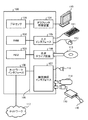
図18は、一つの実施形態による音声処理装置1として機能するコンピュータのハードウェア構成図である。図18に示す通り、音声処理装置1は、コンピュータ100、およびコンピュータ100に接続する入出力装置(周辺機器)を含んで構成される。
(Example 8)
FIG. 18 is a hardware configuration diagram of a computer that functions as the
コンピュータ100は、プロセッサ101によって装置全体が制御されている。プロセッサ101には、バス109を介してRAM(Random Access Memory)102と複数の周辺機器が接続されている。なお、プロセッサ101は、マルチプロセッサであってもよい。また、プロセッサ101は、例えば、CPU、MPU(Micro Processing Unit)、DSP(Digital Signal Processor)、ASIC(Application Specific Integrated Circuit)、またはPLD(Programmable Logic Device)である。更に、プロセッサ101は、CPU、MPU、DSP、ASIC、PLDのうちの2以上の要素の組み合せであってもよい。なお、例えば、プロセッサ101は、図1に記載の取得部2、検出部3、算出部4、判定部5等の機能ブロックの処理を実行することが出来る。例えば、プロセッサ101は、コンピュータプログラムにより実現される機能モジュールとして実現された図1の取得部2、検出部3、算出部4、判定部5の処理を実施することができる。
The
RAM102は、コンピュータ100の主記憶装置として使用される。RAM102には、プロセッサ101に実行させるOS(Operating System)のプログラムやアプリケーションプログラムの少なくとも一部が一時的に格納される。例えば、RAM102には、図1の取得部2、検出部3、算出部4、判定部5の処理を実現する機能モジュールのプログラムの一部が一時的に格納される。また、RAM102には、プロセッサ101による処理に必要な各種データ(例えば、上述の第1閾値ないし第6閾値や、算出部4が算出する相関係数など)が格納される。バス109に接続されている周辺機器としては、HDD(Hard Disk Drive)103、グラフィック処理装置104、入力インタフェース105、光学ドライブ装置106、機器接続インタフェース107およびネットワークインタフェース108がある。
The
HDD103は、内蔵したディスクに対して、磁気的にデータの書き込みおよび読み出しを行う。HDD103は、例えば、コンピュータ100の補助記憶装置として使用される。HDD103には、OSのプログラム、アプリケーションプログラム、および各種データが格納される。なお、補助記憶装置としては、フラッシュメモリなどの半導体記憶装置を使用することも出来る。なお、HDD103に、プロセッサ101による処理に必要な各種データ(例えば、上述の第1閾値ないし第6閾値や、図1の算出部4が算出する相関係数など)が格納されても良い。
The
グラフィック処理装置104には、モニタ110が接続されている。グラフィック処理装置104は、プロセッサ101からの命令にしたがって、各種画像をモニタ110の画面に表示させる。モニタ110としては、CRT(Cathode Ray Tube)を用いた表示装置や液晶表示装置などがある。なお、モニタ110は、例えば、図1の判定部5の判定結果を出力する外部装置に相当する。
A
入力インタフェース105には、キーボード111とマウス112とが接続されている。入力インタフェース105は、キーボード111やマウス112から送られてくる信号をプロセッサ101に送信する。なお、マウス112は、ポインティングデバイスの一例であり、他のポインティングデバイスを使用することもできる。他のポインティングデバイスとしては、タッチパネル、タブレット、タッチパッド、トラックボールなどがある。キーボード111やマウス112は、例えば、音声処理装置1を使用するユーザが、音声処理の開始や終了を指示する場合に使用されれば良い。
A
光学ドライブ装置106は、レーザ光などを利用して、光ディスク113に記録されたデータの読み取りを行う。光ディスク113は、光の反射によって読み取り可能なようにデータが記録された可搬型の記録媒体である。光ディスク113には、DVD(Digital Versatile Disc)、DVD−RAM、CD−ROM(Compact Disc Read Only Memory)、CD−R(Recordable)/RW(ReWritable)などがある。可搬型の記録媒体となる光ディスク113に格納されたプログラムは光学ドライブ装置106を介して音声処理装置1にインストールされる。インストールされた所定のプログラムは、音声処理装置1より実行可能となる。
The
機器接続インタフェース107は、コンピュータ100に周辺機器を接続するための通信インタフェースである。例えば、機器接続インタフェース107には、メモリ装置114やメモリリーダライタ115を接続することが出来る。メモリ装置114は、機器接続インタフェース107との通信機能を搭載した記録媒体である。メモリリーダライタ115は、メモリカード116へのデータの書き込み、またはメモリカード116からのデータの読み出しを行う装置である。メモリカード116は、カード型の記録媒体である。また、機器接続インタフェース107には、マイクロフォン118を(有線または無線通信状態で)接続することができる。なお、マイクロフォン118は、複数接続されており、例えば、第1ユーザの第1音声や第2ユーザの第2音声が入力される。なお、第1音声や第2音声は、例えば、機器接続インタフェース107を介して、プロセッサ101に出力されることで、プロセッサ101は、コンピュータプログラムにより実現される機能モジュールとして実現された図1の取得部2の処理を実行することができる。
The
ネットワークインタフェース108は、ネットワーク117に接続されている。ネットワークインタフェース108は、ネットワーク117を介して、他のコンピュータまたは通信機器との間でデータの送受信を行う。なお、ネットワークインタフェース108は、第1ユーザの第1音声や第2ユーザの第2音声を、ネットワーク117を介して他のコンピュータまたは通信機器から受け取っても良い。この場合、なお、第1音声や第2音声は、例えば、ネットワークインタフェース108を介して、プロセッサ101に出力されることで、プロセッサ101は、コンピュータプログラムにより実現される機能モジュールとして実現された図1の取得部2の処理を実行することができる。
The
コンピュータ100は、たとえば、コンピュータ読み取り可能な記録媒体に記録されたプログラムを実行することにより、上述した音声処理機能を実現する。コンピュータ100に実行させる処理内容を記述したプログラムは、様々な記録媒体に記録しておくことが出来る。上記プログラムは、1つのまたは複数の機能モジュールから構成することが出来る。例えば、図1に記載の取得部2、検出部3、算出部4、判定部5等の処理を実現させた機能モジュールからプログラムを構成することが出来る。なお、コンピュータ100に実行させるプログラムをHDD103に格納しておくことができる。プロセッサ101は、HDD103内のプログラムの少なくとも一部をRAM102にロードし、プログラムを実行する。また、コンピュータ100に実行させるプログラムを、光ディスク113、メモリ装置114、メモリカード116などの可搬型記録媒体に記録しておくことも出来る。可搬型記録媒体に格納されたプログラムは、例えば、プロセッサ101からの制御により、HDD103にインストールされた後、実行可能となる。またプロセッサ101が、可搬型記録媒体から直接プログラムを読み出して実行することも出来る。
The
以上に図示した各装置の各構成要素は、必ずしも物理的に図示の如く構成されていることを要しない。すなわち、各装置の分散・統合の具体的形態は図示のものに限られず、その全部または一部を、各種の負荷や使用状況などに応じて、任意の単位で機能的または物理的に分散・統合して構成することができる。また、上記の実施例で説明した各種の処理は、予め用意されたプログラムをパーソナルコンピュータやワークステーションなどのコンピュータで実行することによって実現することができる。 Each component of each device illustrated above does not necessarily need to be physically configured as illustrated. That is, the specific form of distribution / integration of each device is not limited to the one shown in the figure, and all or a part thereof may be functionally or physically distributed / arbitrarily divided into arbitrary units according to various loads and usage conditions. Can be integrated and configured. The various processes described in the above embodiments can be realized by executing a prepared program on a computer such as a personal computer or a workstation.
以上、説明した実施形態に関し、更に以下の付記を開示する。
(付記1)
第1音声が含まれる第1入力信号と、第2音声が含まれる第2入力信号を取得する取得部と、
前記第1入力信号の第1信号強度と、前記第2入力信号の第2信号強度を検出する検出部と、
前記第1信号強度の時系列と前記第2信号強度の時系列との相関係数を算出する算出部と、
前記相関係数に基づいて、前記第1音声と前記第2音声が会話している状態か否かを判定する判定部
を備えることを特徴とする音声処理装置。
(付記2)
前記判定部は、前記相関係数が負であり、前記相関係数が所定の第1閾値未満の場合に、前記第1音声と前記第2音声が会話している状態と判定することを特徴とする付記1記載の音声処理装置。
(付記3)
前記第1信号強度は前記第1音声のパワーまたは信号対雑音比であり、前記第2信号強度は前記第2音声のパワーまたは信号対雑音比であることを特徴とする付記1または付記2に記載の音声処理装置。
(付記4)
前記検出部は、
前記第1入力信号に含まれる第1発話区間を前記第1信号強度に基づいて検出し、
前記第2入力信号に含まれる第2発話区間を前記第2信号強度に基づいて検出し、
前記第1発話区間と前記第2発話区間が重複する重複発話区間を検出し、
前記算出部は、
前記重複発話区間が所定の第2閾値未満の前記第1信号強度と前記第2信号強度を、前記相関係数の算出に用いないことを特徴とする付記1ないし付記3の何れか一つに記載の音声処理装置。
(付記5)
前記検出部は、
前記第1入力信号に含まれる第1無音区間を前記第1信号強度に基づいて検出し、
前記第2入力信号に含まれる第2無音区間を前記第2信号強度に基づいて検出し、
前記第1無音区間と前記第2無音区間が重複する重複無音区間を検出し、
前記算出部は、
前記重複無音区間が所定の第3閾値未満の前記第1信号強度と前記第2信号強度を、前記相関係数の算出に用いないことを特徴とする付記1ないし付記4の何れか一つに記載の音声処理装置。
(付記6)
前記算出部は、前記第1信号強度の第1位相または、前記第2信号強度の第2位相を所定の範囲で変化させて複数の前記相関係数を算出し、
前記判定部は、複数の前記相関係数のうち最小値となる前記相関係数に基づいて、前記第1音声と前記第2音声が会話している状態か否かを判定することを特徴とする付記1ないし付記5の何れか一つに記載の音声処理装置。
(付記7)
前記検出部は、
前記第1信号強度の時系列と前記第2信号強度の時系列との大小関係を比較し、
前記大小関係が反転する反転回数が所定の第4閾値以上となる相関係数算出区間を検出し、
前記算出部は、
前記相関係数算出区間における前記第1信号強度の時系列と前記第2信号強度の時系列との前記相関係数を算出することを特徴とする付記1ないし付記6の何れか一つに記載の音声処理装置。
(付記8)
前記取得部は、第3音声が含まれる第3入力信号を更に取得し、
前記検出部は、前記第3入力信号の第3信号強度を更に検出し、
前記算出部は、前記第1信号強度の時系列、前記第2信号強度の時系列または前記第3信号強度の時系列のうち、2つの信号強度の組み合わせに対する複数の前記相関係数を算出する算出部と、
前記判定部は、複数の前記相関係数のうち、前記相関係数が最小値となる2つの前記信号強度の組み合せに基づいて、前記第1音声、前記第2音声または前記第3音声から、会話している音声の組み合わせを判定することを特徴とする付記1ないし付記7の何れか一つに記載の音声処理装置。
(付記9)
前記算出部は、前記最小値となる前記相関係数の算出に用いた2つの前記信号強度を加算した加算信号強度を算出し、
前記加算信号強度の時系列と、前記最小値となる前記相関係数の算出に用いた2つの前記信号強度以外の1つの信号強度の時系列との参照相関係数を算出し、
前記判定部は、前記最小値となる前記相関係数が前記参照相関係数を下回る場合、または、前記第1閾値未満の場合に、前記参照相関係数の算出に用いた3つの前記信号強度に基づいて、会話している音声の組み合わせを判定することを特徴とする付記8記載の音声処理装置。
(付記10)
前記算出部は、前記最小値である前記相関係数の算出に用いた2つの前記信号強度の前記重複無音区間が第5閾値以上の場合に、前記参照相関係数を算出することを特徴とする付記9記載の音声処理装置。
(付記11)
前記検出部は、
前記第1入力信号に含まれる前記第2信号強度または、前記第2信号に含まれる前記第1信号強度を更に検出し、
前記算出部は、
前記第1入力信号に含まれる前記第2信号強度の時系列と前記第2入力信号に含まれる前記第2信号強度の時系列との第2相関係数、または、
前記第2入力信号に含まれる前記第1信号強度の時系列と前記第1入力信号に含まれる前記第1信号強度の時系列との第3相関係数を更に算出し、
前記判定部は、前記第2相関係数または前記第3相関係数に基づいて、前記第1音声と前記第2音声が会話している状態か否かを判定することを特徴とする付記1ないし付記10の何れか一つに記載の音声処理装置。
(付記12)
前記判定部は、前記相関係数が正であり、前記第2相関係数が所定の第6閾値以上の場合に、前記第1音声と前記第2音声が前記会話している状態と判定することを特徴とする付記11記載の音声処理装置。
(付記13)
第1音声が含まれる第1入力信号と、第2音声が含まれる第2入力信号を取得し、
前記第1入力信号の第1信号強度と、前記第2入力信号の第2信号強度を検出し、
前記第1信号強度の時系列と前記第2信号強度の時系列との相関係数を算出し、
前記相関係数に基づいて、前記第1音声と前記第2音声が会話している状態か否かを判定することを含む音声処理方法。
(付記14)
前記判定することは、前記相関係数が負であり、前記相関係数が所定の第1閾値未満の場合に、前記第1音声と前記第2音声が前記会話している状態と判定することを特徴とする付記13記載の音声処理方法。
(付記15)
前記第1信号強度または前記第2信号強度は、前記第1音声または前記第2音声のパワーまたは信号対雑音比であることを特徴とする付記13または付記14に記載の音声処理方法。
(付記16)
前記検出することは、
前記第1入力信号に含まれる第1発話区間を前記第1信号強度に基づいて検出し、
前記第2入力信号に含まれる第2発話区間を前記第2信号強度に基づいて検出し、
前記第1発話区間と前記第2発話区間が重複する重複発話区間を検出し、
前記算出部は、
前記重複発話区間が所定の第2閾値未満の前記第1信号強度と前記第2信号強度を、前記相関係数の算出に用いないことを特徴とする付記13ないし付記15の何れか一つに記載の音声処理方法。
(付記17)
前記検出することは、
前記第1入力信号に含まれる第1無音区間を前記第1信号強度に基づいて検出し、
前記第2入力信号に含まれる第2無音区間を前記第2信号強度に基づいて検出し、
前記第1無音区間と前記第2無音区間が重複する重複無音区間を検出し、
前記算出することは、
前記重複無音区間が所定の第3閾値未満の前記第1信号強度と前記第2信号強度を、前記相関係数の算出に用いないことを特徴とする付記13ないし付記16の何れか一つに記載の音声処理方法。
(付記18)
前記算出することは、前記第1信号強度の第1位相または、前記第2信号強度の第2位相を所定の範囲で変化させて複数の前記相関係数を算出し、
前記判定することは、複数の前記相関係数のうち最小値となる前記相関係数に基づいて、前記第1音声と前記第2音声が会話している状態か否かを判定することを特徴とする付記13ないし付記17の何れか一つに記載の音声処理方法。
(付記19)
前記検出することは、
前記第1信号強度の時系列と前記第2信号強度の時系列との大小関係を比較し、
前記大小関係が反転する反転回数が所定の第4閾値以上となる相関係数算出区間を検出し、
前記算出部は、
前記相関係数算出区間における前記第1信号強度の時系列と前記第2信号強度の時系列との前記相関係数を算出することを特徴とする付記13ないし付記18の何れか一つに記載の音声処理方法。
(付記20)
前記取得することは、第3音声が含まれる第3入力信号を更に取得し、
前記検出することは、前記第3入力信号の第3信号強度を更に検出し、
前記算出することは、前記第1信号強度の時系列、前記第2信号強度の時系列または前記第3信号強度の時系列から、2つの信号強度の組み合わせに対する複数の前記相関係数を算出する算出部と、
前記判定部は、複数の前記相関係数のうち、前記相関係数が最小値となる2つの前記信号強度の組み合わせに基づいて、前記第1音声、前記第2音声または前記第3音声から、会話している音声の組み合わせを判定することを特徴とする付記13ないし付記19の何れか一つに記載の音声処理方法。
(付記21)
前記算出することは、前記最小値となる前記相関係数の算出に用いた2つの前記信号強度を加算した加算信号強度を算出し、
前記加算信号強度の時系列と、前記最小値となる前記相関係数の算出に用いた2つの前記信号強度以外の1つの信号強度の時系列との参照相関係数を算出し、
前記判定することは、前記最小値となる前記相関係数が前記参照相関係数を下回る場合、または、前記第1閾値未満の場合に、前記参照相関係数の算出に用いた3つの前記信号強度に基づいて、会話している音声の組み合わせを判定することを特徴とする付記20記載の音声処理方法。
(付記22)
前記算出することは、前記最小値となる前記相関係数の算出に用いた2つの前記信号強度の前記重複無音区間が第5閾値以上の場合に、前記参照相関係数を算出することを特徴とする付記21記載の音声処理方法。
(付記23)
前記検出することは、
前記第1入力信号に含まれる前記2信号強度または、前記第2入力信号に含まれる前記第1信号強度を更に検出し、
前記算出することは、
前記第1入力信号に含まれる前記第2信号強度の時系列と前記第2入力信号に含まれる前記第2信号強度の時系列との第2相関係数、または、
前記第2入力信号に含まれる前記第1信号強度の時系列と前記第1入力信号に含まれる前記第1信号強度の時系列との第3相関係数を更に算出し、
前記判定部は、前記第2相関係数または前記第3相関係数に基づいて、前記第1音声と前記第2音声が会話している状態か否かを判定することを特徴とする付記13ないし付記22の何れか一つに記載の音声処理方法。
(付記24)
前記判定することは、前記相関係数が正であり、前記第2相関係数が所定の第6閾値以上の場合に、前記第1音声と前記第2音声が前記会話している状態と判定することを特徴とする付記23記載の音声処理方法。
(付記25)
コンピュータに
第1音声が含まれる第1入力信号と、第2音声が含まれる第2入力信号を取得し、
前記第1入力信号の第1信号強度と、前記第2入力信号の第2信号強度を検出し、
前記第1信号強度の時系列と前記第2信号強度の時系列との相関係数を算出し、
前記相関係数に基づいて、前記第1音声と前記第2音声が会話している状態か否かを判定する
ことを実行させることを特徴とする音声処理プログラム。
The following supplementary notes are further disclosed regarding the embodiments described above.
(Appendix 1)
An obtaining unit configured to obtain a first input signal including the first sound and a second input signal including the second sound;
A first signal strength of the first input signal, a detection unit for detecting a second signal strength of the second input signal,
A calculating unit that calculates a correlation coefficient between the time series of the first signal strength and the time series of the second signal strength;
An audio processing device, comprising: a determination unit that determines whether or not the first audio and the second audio are in a state of conversation based on the correlation coefficient.
(Appendix 2)
When the correlation coefficient is negative and the correlation coefficient is less than a predetermined first threshold, the determination unit determines that the first voice and the second voice are in a conversation state. 3. The audio processing device according to
(Appendix 3)
Wherein the first signal strength is a power or a signal-to-noise ratio of the first voice, and the second signal strength is a power or a signal-to-noise ratio of the second voice. An audio processing device according to
(Appendix 4)
The detection unit,
Detecting a first utterance section included in the first input signal based on the first signal strength;
Detecting a second utterance section included in the second input signal based on the second signal strength;
Detecting an overlapping utterance section in which the first utterance section and the second utterance section overlap;
The calculation unit,
The
(Appendix 5)
The detection unit,
Detecting a first silent section included in the first input signal based on the first signal strength;
Detecting a second silent section included in the second input signal based on the second signal strength;
Detecting an overlapping silent section in which the first silent section and the second silent section overlap;
The calculation unit,
The
(Appendix 6)
The calculation unit calculates a plurality of the correlation coefficients by changing a first phase of the first signal strength or a second phase of the second signal strength in a predetermined range,
The determination unit determines whether or not the first voice and the second voice are in a state of conversation based on the correlation coefficient that is a minimum value among the plurality of correlation coefficients. 6. The audio processing device according to any one of
(Appendix 7)
The detection unit,
Comparing the magnitude relationship between the time series of the first signal strength and the time series of the second signal strength,
Detecting a correlation coefficient calculation section in which the number of inversions in which the magnitude relationship is inverted is equal to or greater than a predetermined fourth threshold value;
The calculation unit,
7. The
(Appendix 8)
The acquiring unit further acquires a third input signal including a third sound,
The detection unit further detects a third signal strength of the third input signal,
The calculation unit calculates a plurality of correlation coefficients for a combination of two signal strengths in the time series of the first signal strength, the time series of the second signal strength, or the time series of the third signal strength. A calculating unit;
The determination unit is based on a combination of the two signal strengths at which the correlation coefficient has a minimum value among the plurality of correlation coefficients, from the first sound, the second sound, or the third sound, 8. The speech processing device according to any one of
(Appendix 9)
The calculation unit calculates an addition signal strength obtained by adding the two signal strengths used for calculating the correlation coefficient that is the minimum value,
A time series of the added signal strength, and a reference correlation coefficient between a time series of one signal strength other than the two signal strengths used for calculating the correlation coefficient that is the minimum value,
When the correlation coefficient that is the minimum value is lower than the reference correlation coefficient, or when the correlation coefficient is less than the first threshold, the determination unit determines the three signal intensities used for calculating the reference correlation coefficient. 9. The speech processing device according to
(Appendix 10)
The calculating unit calculates the reference correlation coefficient when the overlapping silent section of the two signal intensities used for calculating the correlation coefficient that is the minimum value is equal to or greater than a fifth threshold. 9. The audio processing device according to supplementary note 9, wherein
(Appendix 11)
The detection unit,
The second signal strength included in the first input signal or the first signal strength included in the second signal is further detected,
The calculation unit,
A second correlation coefficient between the time series of the second signal strength included in the first input signal and the time series of the second signal strength included in the second input signal, or
Further calculating a third correlation coefficient between the time series of the first signal strength included in the second input signal and the time series of the first signal strength included in the first input signal;
(Appendix 12)
The determining unit determines that the first voice and the second voice are in the talking state when the correlation coefficient is positive and the second correlation coefficient is equal to or greater than a predetermined sixth threshold. 13. The voice processing device according to claim 11, wherein
(Appendix 13)
Obtaining a first input signal including a first voice and a second input signal including a second voice;
Detecting a first signal strength of the first input signal and a second signal strength of the second input signal;
Calculating a correlation coefficient between the time series of the first signal strength and the time series of the second signal strength;
An audio processing method comprising: determining whether or not the first audio and the second audio are in a conversation based on the correlation coefficient.
(Appendix 14)
The determining may include determining that the first voice and the second voice are in the talking state when the correlation coefficient is negative and the correlation coefficient is less than a predetermined first threshold. 14. The speech processing method according to supplementary note 13, wherein
(Appendix 15)
15. The audio processing method according to claim 13, wherein the first signal strength or the second signal strength is a power or a signal-to-noise ratio of the first sound or the second sound.
(Appendix 16)
The detecting comprises:
Detecting a first utterance section included in the first input signal based on the first signal strength;
Detecting a second utterance section included in the second input signal based on the second signal strength;
Detecting an overlapping utterance section in which the first utterance section and the second utterance section overlap;
The calculation unit,
The supplementary note 13 to the supplementary note 15, wherein the first signal strength and the second signal strength whose overlapping utterance section is less than a predetermined second threshold are not used for calculating the correlation coefficient. The described speech processing method.
(Appendix 17)
The detecting comprises:
Detecting a first silent section included in the first input signal based on the first signal strength;
Detecting a second silent section included in the second input signal based on the second signal strength;
Detecting an overlapping silent section in which the first silent section and the second silent section overlap;
The calculating comprises:
The supplementary note 13 to supplementary note 16, wherein the first signal strength and the second signal strength whose overlapping silent section is less than a predetermined third threshold are not used for calculating the correlation coefficient. The described speech processing method.
(Appendix 18)
The calculating includes calculating a plurality of the correlation coefficients by changing a first phase of the first signal strength or a second phase of the second signal strength within a predetermined range,
The determining may include determining whether or not the first voice and the second voice are in a state of conversation based on the smallest correlation coefficient among the plurality of correlation coefficients. 18. The speech processing method according to any one of supplementary notes 13 to 17, wherein
(Appendix 19)
The detecting comprises:
Comparing the magnitude relationship between the time series of the first signal strength and the time series of the second signal strength,
Detecting a correlation coefficient calculation section in which the number of inversions in which the magnitude relationship is inverted is equal to or greater than a predetermined fourth threshold value;
The calculation unit,
19. The supplementary note 13 to claim 18, wherein the correlation coefficient between the time series of the first signal strength and the time series of the second signal strength in the correlation coefficient calculation section is calculated. Voice processing method.
(Appendix 20)
The obtaining further obtains a third input signal including a third sound,
The detecting further comprises detecting a third signal strength of the third input signal;
The calculating includes calculating a plurality of correlation coefficients for a combination of two signal intensities from a time series of the first signal strength, a time series of the second signal strength, or a time series of the third signal strength. A calculating unit;
The determination unit is based on a combination of the two signal intensities at which the correlation coefficient has a minimum value among the plurality of correlation coefficients, from the first sound, the second sound, or the third sound, 20. The speech processing method according to any one of supplementary notes 13 to 19, wherein a combination of conversational speeches is determined.
(Appendix 21)
The calculating is calculating an addition signal strength obtained by adding the two signal strengths used for calculating the correlation coefficient that is the minimum value,
A time series of the added signal strength, and a reference correlation coefficient between a time series of one signal strength other than the two signal strengths used for calculating the correlation coefficient that is the minimum value,
The determining is performed when the correlation coefficient that is the minimum value is lower than the reference correlation coefficient, or when the correlation coefficient is less than the first threshold, the three signals used for calculating the reference correlation coefficient. 21. The voice processing method according to
(Appendix 22)
The calculating includes calculating the reference correlation coefficient when the overlapping silent section of the two signal intensities used for calculating the minimum correlation coefficient is equal to or greater than a fifth threshold value. 23. A speech processing method according to claim 21, wherein
(Appendix 23)
The detecting comprises:
Further detecting the two signal strengths included in the first input signal or the first signal strength included in the second input signal;
The calculating comprises:
A second correlation coefficient between the time series of the second signal strength included in the first input signal and the time series of the second signal strength included in the second input signal, or
Further calculating a third correlation coefficient between the time series of the first signal strength included in the second input signal and the time series of the first signal strength included in the first input signal;
The determination unit determines whether the first voice and the second voice are in a conversation state based on the second correlation coefficient or the third correlation coefficient. 23. The speech processing method according to any one of supplementary notes 22.
(Appendix 24)
The determining may include determining that the first voice and the second voice are in the talking state when the correlation coefficient is positive and the second correlation coefficient is equal to or greater than a predetermined sixth threshold. 23. The speech processing method according to Supplementary Note 23, wherein:
(Appendix 25)
A computer obtains a first input signal including the first sound and a second input signal including the second sound;
Detecting a first signal strength of the first input signal and a second signal strength of the second input signal;
Calculating a correlation coefficient between the time series of the first signal strength and the time series of the second signal strength;
Determining whether or not the first voice and the second voice are in a state of conversation based on the correlation coefficient.
1 音声処理装置
2 取得部
3 検出部
4 算出部
5 判定部
DESCRIPTION OF
Claims (13)
前記第1入力信号の第1信号強度と、前記第2入力信号の第2信号強度を検出する検出部と、
前記第1信号強度の時系列と前記第2信号強度の時系列との相関係数を算出する算出部と、
前記相関係数に基づいて、前記第1音声と前記第2音声が会話している状態か否かを判定する判定部と、を有し、
前記検出部は、
前記第1入力信号に含まれる第1発話区間を前記第1信号強度に基づいて検出し、
前記第2入力信号に含まれる第2発話区間を前記第2信号強度に基づいて検出し、
前記第1発話区間と前記第2発話区間が重複する重複発話区間を検出し、
前記算出部は、
前記重複発話区間が所定の第2閾値未満の前記第1信号強度と前記第2信号強度以外の前記第1信号強度の時系列と前記第2信号強度の時系列との前記相関係数を算出することを特徴とする音声処理装置。 An obtaining unit configured to obtain a first input signal including the first sound and a second input signal including the second sound;
A first signal strength of the first input signal, a detection unit for detecting a second signal strength of the second input signal,
A calculating unit that calculates a correlation coefficient between the time series of the first signal strength and the time series of the second signal strength;
A determining unit that determines whether or not the first voice and the second voice are in a state of talking based on the correlation coefficient ,
The detection unit,
Detecting a first utterance section included in the first input signal based on the first signal strength;
Detecting a second utterance section included in the second input signal based on the second signal strength;
Detecting an overlapping utterance section in which the first utterance section and the second utterance section overlap;
The calculation unit,
Calculating the correlation coefficient between the time series of the first signal strength and the time series of the second signal strength other than the first signal strength and the second signal strength in which the overlapping speech section is less than a predetermined second threshold value. An audio processing device characterized by performing.
前記第1入力信号に含まれる第1無音区間を前記第1信号強度に基づいて検出し、
前記第2入力信号に含まれる第2無音区間を前記第2信号強度に基づいて検出し、
前記第1無音区間と前記第2無音区間が重複する重複無音区間を検出し、
前記算出部は、
前記重複無音区間が所定の第3閾値未満の前記第1信号強度と前記第2信号強度を、前記相関係数の算出に用いないことを特徴とする請求項1ないし請求項3の何れか一項に記載の音声処理装置。 The detection unit,
Detecting a first silent section included in the first input signal based on the first signal strength;
Detecting a second silent section included in the second input signal based on the second signal strength;
Detecting an overlapping silent section in which the first silent section and the second silent section overlap;
The calculation unit,
The overlapping the second signal strength and the first signal strength of the silence section is less than a predetermined third threshold value, any one of claims 1 to 3, characterized in that it is used for calculation of the correlation coefficient one An audio processing device according to the item.
前記判定部は、複数の前記相関係数のうち最小値となる前記相関係数に基づいて、前記第1音声と前記第2音声が会話している状態か否かを判定することを特徴とする請求項1ないし請求項4の何れか一項に記載の音声処理装置。 The calculation unit calculates a plurality of the correlation coefficients by changing a first phase of the first signal strength or a second phase of the second signal strength in a predetermined range,
The determination unit determines whether or not the first voice and the second voice are in a state of conversation based on the correlation coefficient that is a minimum value among the plurality of correlation coefficients. speech processing apparatus according to any one of claims 1 to 4.
前記第1信号強度の時系列と前記第2信号強度の時系列との大小関係を比較し、
前記大小関係が反転する反転回数が所定の第4閾値以上となる相関係数算出区間を検出し、
前記算出部は、
前記相関係数算出区間における前記第1信号強度の時系列と前記第2信号強度の時系列との前記相関係数を算出することを特徴とする請求項1ないし請求項5の何れか一項に記載の音声処理装置。 The detection unit,
Comparing the magnitude relationship between the time series of the first signal strength and the time series of the second signal strength,
Detecting a correlation coefficient calculation section in which the number of inversions in which the magnitude relationship is inverted is equal to or greater than a predetermined fourth threshold value;
The calculation unit,
Any one of claims 1 to 5, and calculates the correlation coefficient between time-series of sequence and the second signal strength when the first signal strength at the correlation coefficient calculating section An audio processing device according to claim 1.
前記検出部は、前記第3入力信号の第3信号強度を更に検出し、
前記算出部は、前記第1信号強度の時系列、前記第2信号強度の時系列または前記第3信号強度の時系列のうち、2つの信号強度の組み合わせに対する複数の前記相関係数を算出し、
前記判定部は、複数の前記相関係数のうち、前記相関係数が最小値となる2つの前記信号強度の組み合わせに基づいて、前記第1音声、前記第2音声または前記第3音声から、会話している音声の組み合わせを判定することを特徴とする請求項1ないし請求項6の何れか一項に記載の音声処理装置。 The acquiring unit further acquires a third input signal including a third sound,
The detection unit further detects a third signal strength of the third input signal,
The calculating unit, the time series of the first signal strength, among the time series of time series or said third signal intensity of the second signal strength, and calculates a plurality of the correlation coefficients for the combination of the two signal intensities ,
The determination unit is based on a combination of the two signal intensities at which the correlation coefficient has a minimum value among the plurality of correlation coefficients, from the first sound, the second sound, or the third sound, speech processing apparatus according to any one of claims 1 to 6, characterized in that to determine the combination of voice is speaking.
前記加算信号強度の時系列と、前記最小値となる前記相関係数の算出に用いた2つの前記信号強度以外の1つの信号強度の時系列との参照相関係数を算出し、
前記判定部は、前記相関係数が負であり、前記相関係数が所定の第1閾値未満の場合に、前記第1音声と前記第2音声が会話している状態と判定し、
前記最小値となる前記相関係数が前記参照相関係数を下回る場合、または、前記第1閾値未満の場合に、前記参照相関係数の算出に用いた3つの前記信号強度に基づいて、会話している音声の組み合わせを判定することを特徴とする請求項7記載の音声処理装置。 The calculation unit calculates an addition signal strength obtained by adding the two signal strengths used for calculating the correlation coefficient that is the minimum value,
A time series of the added signal strength, and a reference correlation coefficient between a time series of one signal strength other than the two signal strengths used for calculating the correlation coefficient that is the minimum value,
The determination unit determines that the first voice and the second voice are in a state of conversation when the correlation coefficient is negative and the correlation coefficient is less than a first threshold.
If the minimum correlation coefficient is less than the reference correlation coefficient, or if the correlation coefficient is less than the first threshold, a conversation is performed based on the three signal intensities used for calculating the reference correlation coefficient. The voice processing apparatus according to claim 7, wherein a combination of the voices is determined.
前記第1入力信号に含まれる第1無音区間を前記第1信号強度に基づいて検出し、
前記第2入力信号に含まれる第2無音区間を前記第2信号強度に基づいて検出し、
前記第1無音区間と前記第2無音区間が重複する重複無音区間を検出し、
前記算出部は、前記最小値となる前記相関係数の算出に用いた2つの前記信号強度の前記重複無音区間が第5閾値以上の場合に、前記参照相関係数を算出することを特徴とする請求項8記載の音声処理装置。 The detection unit,
Detecting a first silent section included in the first input signal based on the first signal strength;
Detecting a second silent section included in the second input signal based on the second signal strength;
Detecting an overlapping silent section in which the first silent section and the second silent section overlap;
Wherein the calculating unit calculates the reference correlation coefficient when the overlapping silent section of the two signal intensities used for calculating the correlation coefficient that is the minimum value is equal to or greater than a fifth threshold. 9. The audio processing device according to claim 8, wherein
前記第1入力信号に含まれる前記第2信号強度または、前記第2入力信号に含まれる前記第1信号強度を更に検出し、
前記算出部は、
前記第1入力信号に含まれる前記第2信号強度の時系列と前記第2入力信号に含まれる前記第2信号強度の時系列との第2相関係数、または、
前記第2入力信号に含まれる前記第1信号強度の時系列と前記第1入力信号に含まれる前記第1信号強度の時系列との第3相関係数を更に算出し、
前記判定部は、前記第2相関係数または前記第3相関係数に基づいて、前記第1音声と前記第2音声が会話している状態か否かを判定することを特徴とする請求項1ないし請求項9の何れか一項に記載の音声処理装置。 The detection unit,
The second signal strength included in the first input signal or the first signal strength included in the second input signal is further detected,
The calculation unit,
A second correlation coefficient between the time series of the second signal strength included in the first input signal and the time series of the second signal strength included in the second input signal, or
Further calculating a third correlation coefficient between the time series of the first signal strength included in the second input signal and the time series of the first signal strength included in the first input signal;
The said judgment part judges whether the said 1st audio | voice and the said 2nd audio | voice are in the state which is talking based on the said 2nd correlation coefficient or the said 3rd correlation coefficient. The audio processing device according to any one of claims 1 to 9 .
前記第1入力信号の第1信号強度と、前記第2入力信号の第2信号強度を検出し、
前記第1入力信号に含まれる第1発話区間を前記第1信号強度に基づいて検出し、
前記第2入力信号に含まれる第2発話区間を前記第2信号強度に基づいて検出し、
前記第1発話区間と前記第2発話区間が重複する重複発話区間を検出し、
前記重複発話区間が所定の第2閾値未満の前記第1信号強度と前記第2信号強度以外の前記第1信号強度の時系列と前記第2信号強度の時系列との相関係数を算出し、
前記相関係数に基づいて、前記第1音声と前記第2音声が会話している状態か否かを判定することを含む音声処理方法。 Obtaining a first input signal including a first voice and a second input signal including a second voice;
Detecting a first signal strength of the first input signal and a second signal strength of the second input signal;
Detecting a first utterance section included in the first input signal based on the first signal strength;
Detecting a second utterance section included in the second input signal based on the second signal strength;
Detecting an overlapping utterance section in which the first utterance section and the second utterance section overlap;
Calculating a correlation coefficient between the time series of the first signal strength and the time series of the second signal strength other than the first signal strength and the second signal strength in which the overlapping speech section is less than a predetermined second threshold value; ,
An audio processing method comprising: determining whether or not the first audio and the second audio are in a conversation based on the correlation coefficient.
第1音声が含まれる第1入力信号と、第2音声が含まれる第2入力信号を取得し、
前記第1入力信号の第1信号強度と、前記第2入力信号の第2信号強度を検出し、
前記第1入力信号に含まれる第1発話区間を前記第1信号強度に基づいて検出し、
前記第2入力信号に含まれる第2発話区間を前記第2信号強度に基づいて検出し、
前記第1発話区間と前記第2発話区間が重複する重複発話区間を検出し、
前記重複発話区間が所定の第2閾値未満の前記第1信号強度と前記第2信号強度以外の前記第1信号強度の時系列と前記第2信号強度の時系列との相関係数を算出し、
前記相関係数に基づいて、前記第1音声と前記第2音声が会話している状態か否かを判定する
ことを実行させることを特徴とする音声処理プログラム。 A computer obtains a first input signal including the first sound and a second input signal including the second sound;
Detecting a first signal strength of the first input signal and a second signal strength of the second input signal;
Detecting a first utterance section included in the first input signal based on the first signal strength;
Detecting a second utterance section included in the second input signal based on the second signal strength;
Detecting an overlapping utterance section in which the first utterance section and the second utterance section overlap;
Calculating a correlation coefficient between the time series of the first signal strength and the time series of the second signal strength other than the first signal strength and the second signal strength in which the overlapping speech section is less than a predetermined second threshold value; ,
Determining whether or not the first voice and the second voice are in a state of conversation based on the correlation coefficient.
Priority Applications (3)
| Application Number | Priority Date | Filing Date | Title |
|---|---|---|---|
| JP2015186617A JP6641832B2 (en) | 2015-09-24 | 2015-09-24 | Audio processing device, audio processing method, and audio processing program |
| EP16188938.1A EP3147903B1 (en) | 2015-09-24 | 2016-09-15 | Voice processing apparatus, voice processing method, and non-transitory computer-readable storage medium |
| US15/266,057 US9916843B2 (en) | 2015-09-24 | 2016-09-15 | Voice processing apparatus, voice processing method, and non-transitory computer-readable storage medium to determine whether voice signals are in a conversation state |
Applications Claiming Priority (1)
| Application Number | Priority Date | Filing Date | Title |
|---|---|---|---|
| JP2015186617A JP6641832B2 (en) | 2015-09-24 | 2015-09-24 | Audio processing device, audio processing method, and audio processing program |
Publications (2)
| Publication Number | Publication Date |
|---|---|
| JP2017062307A JP2017062307A (en) | 2017-03-30 |
| JP6641832B2 true JP6641832B2 (en) | 2020-02-05 |
Family
ID=56936348
Family Applications (1)
| Application Number | Title | Priority Date | Filing Date |
|---|---|---|---|
| JP2015186617A Active JP6641832B2 (en) | 2015-09-24 | 2015-09-24 | Audio processing device, audio processing method, and audio processing program |
Country Status (3)
| Country | Link |
|---|---|
| US (1) | US9916843B2 (en) |
| EP (1) | EP3147903B1 (en) |
| JP (1) | JP6641832B2 (en) |
Families Citing this family (6)
| Publication number | Priority date | Publication date | Assignee | Title |
|---|---|---|---|---|
| JP6565500B2 (en) * | 2015-08-31 | 2019-08-28 | 富士通株式会社 | Utterance state determination device, utterance state determination method, and determination program |
| JP7143574B2 (en) * | 2017-07-18 | 2022-09-29 | 富士通株式会社 | Evaluation program, evaluation method and evaluation device |
| US10528600B1 (en) * | 2017-09-13 | 2020-01-07 | Hrl Laboratories, Llc | System to identify unknown communication behavior relationships from time series |
| US11195107B1 (en) * | 2017-09-13 | 2021-12-07 | Hrl Laboratories, Llc | Method of malicious social activity prediction using spatial-temporal social network data |
| US10629226B1 (en) * | 2018-10-29 | 2020-04-21 | Bestechnic (Shanghai) Co., Ltd. | Acoustic signal processing with voice activity detector having processor in an idle state |
| CN117461323A (en) * | 2021-06-08 | 2024-01-26 | 索尼集团公司 | Information processing device, information processing method, information processing program, and information processing system |
Family Cites Families (19)
| Publication number | Priority date | Publication date | Assignee | Title |
|---|---|---|---|---|
| JP4168539B2 (en) | 1999-08-03 | 2008-10-22 | 富士ゼロックス株式会社 | Dialog information distribution system and dialog information distribution apparatus |
| JP2004133403A (en) * | 2002-09-20 | 2004-04-30 | Kobe Steel Ltd | Sound signal processing apparatus |
| US7617094B2 (en) * | 2003-02-28 | 2009-11-10 | Palo Alto Research Center Incorporated | Methods, apparatus, and products for identifying a conversation |
| JP3940723B2 (en) * | 2004-01-14 | 2007-07-04 | 株式会社東芝 | Dialog information analyzer |
| JP2008134557A (en) | 2006-11-29 | 2008-06-12 | Fujitsu Ltd | Mobile terminal device |
| JP4364251B2 (en) * | 2007-03-28 | 2009-11-11 | 株式会社東芝 | Apparatus, method and program for detecting dialog |
| EP2342867A1 (en) * | 2008-09-18 | 2011-07-13 | Koninklijke Philips Electronics N.V. | Conversation detection in an ambient telephony system |
| JP5385677B2 (en) | 2009-05-12 | 2014-01-08 | 日本電信電話株式会社 | Dialog state dividing apparatus and method, program and recording medium |
| CN102388416B (en) * | 2010-02-25 | 2014-12-10 | 松下电器产业株式会社 | Signal processing apparatus and signal processing method |
| WO2012042768A1 (en) * | 2010-09-28 | 2012-04-05 | パナソニック株式会社 | Speech processing device and speech processing method |
| JP5803617B2 (en) * | 2011-11-29 | 2015-11-04 | 富士通株式会社 | Speech information analysis apparatus and speech information analysis program |
| JP6031761B2 (en) * | 2011-12-28 | 2016-11-24 | 富士ゼロックス株式会社 | Speech analysis apparatus and speech analysis system |
| JP2013140534A (en) * | 2012-01-06 | 2013-07-18 | Fuji Xerox Co Ltd | Voice analysis device, voice analysis system, and program |
| US20130304476A1 (en) | 2012-05-11 | 2013-11-14 | Qualcomm Incorporated | Audio User Interaction Recognition and Context Refinement |
| US9443521B1 (en) * | 2013-02-14 | 2016-09-13 | Sociometric Solutions, Inc. | Methods for automatically analyzing conversational turn-taking patterns |
| US9118751B2 (en) * | 2013-03-15 | 2015-08-25 | Marchex, Inc. | System and method for analyzing and classifying calls without transcription |
| US10141011B2 (en) * | 2014-04-21 | 2018-11-27 | Avaya Inc. | Conversation quality analysis |
| JP2015222847A (en) * | 2014-05-22 | 2015-12-10 | 富士通株式会社 | Voice processing device, voice processing method and voice processing program |
| JP6524674B2 (en) * | 2015-01-22 | 2019-06-05 | 富士通株式会社 | Voice processing apparatus, voice processing method and voice processing program |
-
2015
- 2015-09-24 JP JP2015186617A patent/JP6641832B2/en active Active
-
2016
- 2016-09-15 US US15/266,057 patent/US9916843B2/en active Active
- 2016-09-15 EP EP16188938.1A patent/EP3147903B1/en active Active
Also Published As
| Publication number | Publication date |
|---|---|
| US20170092294A1 (en) | 2017-03-30 |
| JP2017062307A (en) | 2017-03-30 |
| US9916843B2 (en) | 2018-03-13 |
| EP3147903B1 (en) | 2018-08-22 |
| EP3147903A3 (en) | 2017-04-19 |
| EP3147903A2 (en) | 2017-03-29 |
Similar Documents
| Publication | Publication Date | Title |
|---|---|---|
| JP6641832B2 (en) | Audio processing device, audio processing method, and audio processing program | |
| US9293133B2 (en) | Improving voice communication over a network | |
| CN112071328B (en) | Audio noise reduction | |
| JP2021503633A (en) | Voice noise reduction methods, devices, servers and storage media | |
| EP2538404A1 (en) | Voice data transferring device, terminal device, voice data transferring method, and voice recognition system | |
| US7672844B2 (en) | Voice processing apparatus | |
| US20090018826A1 (en) | Methods, Systems and Devices for Speech Transduction | |
| JP2009518662A (en) | Determining audio device quality | |
| JPWO2011105003A1 (en) | Signal processing apparatus and signal processing method | |
| JP2016046695A (en) | Acoustic quality evaluation device, acoustic quality evaluation method, and program | |
| Chatterjee et al. | ClearBuds: wireless binaural earbuds for learning-based speech enhancement | |
| JP6524674B2 (en) | Voice processing apparatus, voice processing method and voice processing program | |
| JP2024507916A (en) | Audio signal processing method, device, electronic device, and computer program | |
| JP2015222847A (en) | Voice processing device, voice processing method and voice processing program | |
| EP3755005A1 (en) | Howling suppression device, method therefor, and program | |
| EP3913904B1 (en) | Training a model for speech and noise energy estimation | |
| JP2017068061A (en) | Communication terminal and voice recognition system | |
| Gowda et al. | Quasi-closed phase forward-backward linear prediction analysis of speech for accurate formant detection and estimation | |
| US11551707B2 (en) | Speech processing method, information device, and computer program product | |
| JP2017049364A (en) | Utterance state determination device, utterance state determination method, and determination program | |
| JP2012168296A (en) | Speech-based suppressed state detecting device and program | |
| JP6394103B2 (en) | Audio processing apparatus, audio processing method, and audio processing program | |
| JP2010026323A (en) | Speech speed detection device | |
| JP2013235050A (en) | Information processing apparatus and method, and program | |
| US11205416B2 (en) | Non-transitory computer-read able storage medium for storing utterance detection program, utterance detection method, and utterance detection apparatus |
Legal Events
| Date | Code | Title | Description |
|---|---|---|---|
| RD01 | Notification of change of attorney |
Free format text: JAPANESE INTERMEDIATE CODE: A7421 Effective date: 20160401 |
|
| RD01 | Notification of change of attorney |
Free format text: JAPANESE INTERMEDIATE CODE: A7421 Effective date: 20180528 |
|
| A621 | Written request for application examination |
Free format text: JAPANESE INTERMEDIATE CODE: A621 Effective date: 20180608 |
|
| A977 | Report on retrieval |
Free format text: JAPANESE INTERMEDIATE CODE: A971007 Effective date: 20190408 |
|
| A131 | Notification of reasons for refusal |
Free format text: JAPANESE INTERMEDIATE CODE: A131 Effective date: 20190507 |
|
| A521 | Written amendment |
Free format text: JAPANESE INTERMEDIATE CODE: A523 Effective date: 20190708 |
|
| TRDD | Decision of grant or rejection written | ||
| A01 | Written decision to grant a patent or to grant a registration (utility model) |
Free format text: JAPANESE INTERMEDIATE CODE: A01 Effective date: 20191203 |
|
| A61 | First payment of annual fees (during grant procedure) |
Free format text: JAPANESE INTERMEDIATE CODE: A61 Effective date: 20191216 |
|
| R150 | Certificate of patent or registration of utility model |
Ref document number: 6641832 Country of ref document: JP Free format text: JAPANESE INTERMEDIATE CODE: R150 |