EP3432290B1 - Warning device - Google Patents
Warning device Download PDFInfo
- Publication number
- EP3432290B1 EP3432290B1 EP17193599.2A EP17193599A EP3432290B1 EP 3432290 B1 EP3432290 B1 EP 3432290B1 EP 17193599 A EP17193599 A EP 17193599A EP 3432290 B1 EP3432290 B1 EP 3432290B1
- Authority
- EP
- European Patent Office
- Prior art keywords
- supporting
- base
- warning device
- standing
- supporting rod
- Prior art date
- Legal status (The legal status is an assumption and is not a legal conclusion. Google has not performed a legal analysis and makes no representation as to the accuracy of the status listed.)
- Active
Links
Images


Classifications
-
- E—FIXED CONSTRUCTIONS
- E01—CONSTRUCTION OF ROADS, RAILWAYS, OR BRIDGES
- E01F—ADDITIONAL WORK, SUCH AS EQUIPPING ROADS OR THE CONSTRUCTION OF PLATFORMS, HELICOPTER LANDING STAGES, SIGNS, SNOW FENCES, OR THE LIKE
- E01F9/00—Arrangement of road signs or traffic signals; Arrangements for enforcing caution
- E01F9/60—Upright bodies, e.g. marker posts or bollards; Supports for road signs
- E01F9/688—Free-standing bodies
- E01F9/692—Portable base members therefor
-
- E—FIXED CONSTRUCTIONS
- E01—CONSTRUCTION OF ROADS, RAILWAYS, OR BRIDGES
- E01F—ADDITIONAL WORK, SUCH AS EQUIPPING ROADS OR THE CONSTRUCTION OF PLATFORMS, HELICOPTER LANDING STAGES, SIGNS, SNOW FENCES, OR THE LIKE
- E01F9/00—Arrangement of road signs or traffic signals; Arrangements for enforcing caution
- E01F9/60—Upright bodies, e.g. marker posts or bollards; Supports for road signs
- E01F9/604—Upright bodies, e.g. marker posts or bollards; Supports for road signs specially adapted for particular signalling purposes, e.g. for indicating curves, road works or pedestrian crossings
- E01F9/608—Upright bodies, e.g. marker posts or bollards; Supports for road signs specially adapted for particular signalling purposes, e.g. for indicating curves, road works or pedestrian crossings for guiding, warning or controlling traffic, e.g. delineator posts or milestones
-
- B—PERFORMING OPERATIONS; TRANSPORTING
- B60—VEHICLES IN GENERAL
- B60Q—ARRANGEMENT OF SIGNALLING OR LIGHTING DEVICES, THE MOUNTING OR SUPPORTING THEREOF OR CIRCUITS THEREFOR, FOR VEHICLES IN GENERAL
- B60Q7/00—Arrangement or adaptation of portable emergency signal devices on vehicles
- B60Q7/005—Devices without lamps
-
- E—FIXED CONSTRUCTIONS
- E01—CONSTRUCTION OF ROADS, RAILWAYS, OR BRIDGES
- E01F—ADDITIONAL WORK, SUCH AS EQUIPPING ROADS OR THE CONSTRUCTION OF PLATFORMS, HELICOPTER LANDING STAGES, SIGNS, SNOW FENCES, OR THE LIKE
- E01F9/00—Arrangement of road signs or traffic signals; Arrangements for enforcing caution
- E01F9/60—Upright bodies, e.g. marker posts or bollards; Supports for road signs
- E01F9/623—Upright bodies, e.g. marker posts or bollards; Supports for road signs characterised by form or by structural features, e.g. for enabling displacement or deflection
- E01F9/646—Upright bodies, e.g. marker posts or bollards; Supports for road signs characterised by form or by structural features, e.g. for enabling displacement or deflection extensible, collapsible or pivotable
-
- E—FIXED CONSTRUCTIONS
- E01—CONSTRUCTION OF ROADS, RAILWAYS, OR BRIDGES
- E01F—ADDITIONAL WORK, SUCH AS EQUIPPING ROADS OR THE CONSTRUCTION OF PLATFORMS, HELICOPTER LANDING STAGES, SIGNS, SNOW FENCES, OR THE LIKE
- E01F9/00—Arrangement of road signs or traffic signals; Arrangements for enforcing caution
- E01F9/60—Upright bodies, e.g. marker posts or bollards; Supports for road signs
- E01F9/658—Upright bodies, e.g. marker posts or bollards; Supports for road signs characterised by means for fixing
-
- E—FIXED CONSTRUCTIONS
- E01—CONSTRUCTION OF ROADS, RAILWAYS, OR BRIDGES
- E01F—ADDITIONAL WORK, SUCH AS EQUIPPING ROADS OR THE CONSTRUCTION OF PLATFORMS, HELICOPTER LANDING STAGES, SIGNS, SNOW FENCES, OR THE LIKE
- E01F9/00—Arrangement of road signs or traffic signals; Arrangements for enforcing caution
- E01F9/60—Upright bodies, e.g. marker posts or bollards; Supports for road signs
- E01F9/688—Free-standing bodies
-
- E—FIXED CONSTRUCTIONS
- E01—CONSTRUCTION OF ROADS, RAILWAYS, OR BRIDGES
- E01F—ADDITIONAL WORK, SUCH AS EQUIPPING ROADS OR THE CONSTRUCTION OF PLATFORMS, HELICOPTER LANDING STAGES, SIGNS, SNOW FENCES, OR THE LIKE
- E01F9/00—Arrangement of road signs or traffic signals; Arrangements for enforcing caution
- E01F9/60—Upright bodies, e.g. marker posts or bollards; Supports for road signs
- E01F9/70—Storing, transporting, placing or retrieving portable devices
-
- G—PHYSICS
- G08—SIGNALLING
- G08G—TRAFFIC CONTROL SYSTEMS
- G08G1/00—Traffic control systems for road vehicles
- G08G1/09—Arrangements for giving variable traffic instructions
- G08G1/095—Traffic lights
- G08G1/0955—Traffic lights transportable
Definitions
- the subject matter herein generally relates to a warning device using driving mechanisms.
- Rear-end collisions can occur when advance-warning of a breakdown for example is not given by the vehicle ahead. Rear-end collisions are also caused by the poor visibility and closeness to the warning equipment of the broken-down vehicle, the vehicles following do not have sufficient time or distance to respond. As required by transportation authorities, after an accident, an advance-warning device must be used to warn the vehicles behind, at a distance of 100-250 meters. However, when a warning device is manually placed, safety of the placer can be at risk. Therefore, a warning device that can be self propelled would be beneficial.
- the patent CN203603083U discloses a remote control warning sign with foldable warning rack.
- the remote control warning sign of CN203603083U reaches the designated position through remote control to prevent from risk, but the body is supported by two bigger roller and one smaller roller, because rollers are not stable supporting elements, thus the stability of the remote control warning sign is poor, furthermore, the structure connected the smaller roller and the body is complex, which occupies a large space and is not convenient to be received in the body.
- substantially is defined to be essentially conforming to the particular dimension, shape, or other feature that the term modifies, such that the component need not be exact.
- substantially cylindrical means that the object resembles a cylinder, but can have one or more deviations from a true cylinder.
- comprising means “including, but not necessarily limited to”; it specifically indicates open-ended inclusion or membership in a so-described combination, group, series, and the like.
- FIGS. 1 to 3 illustrate a warning device 100 in a first exemplary embodiment.
- the warning device 100 includes a warning sign 20 and a propelling mechanism 200, the warning sign 20 is installed to an upper side of the driving mechanism 200.
- the warning sign can be a warning triangle.
- the driving mechanism includes a base 10, a driving unit 60, two wheels 30, a plurality of supporting units 50, and a plurality of driving members (not shown).
- the base 10 defines an accommodating space 140, the driving unit 60 is accommodated in the accommodating space 140.
- the two wheels 30 are connected to the driving unit.
- the two wheels 30 are driven by the driving unit, so that the warning device 100 is self-propelled.
- the driving unit 60 is a motor, the driving mechanism includes two wheels 30 connected to ends of the base 10.
- the driving mechanism 200 of the warning device 100 further includes a standing unit 40.
- the standing unit 40 is connected to a lower side of a central portion of the base 10.
- the standing unit 40 includes a standing bar 410 and a standing wheel 420, the standing wheel 420 is rotatably connected to the standing bar 410.
- the standing bar 410 is connected to a lower side of a central portion of the base 10, so that the standing wheel 420 and the two wheels 30 form a triangle, and the warning device 100 is supported by the standing wheel 420 and the two wheels 30 so as to be upright when the warning device 100 is self-propelled.
- a plurality of supporting units 50 are movably connected to the base 10.
- a plurality of driving members are respectively connected to the supporting units.
- Each of the supporting units 50 is movable between a receiving position (as shown in FIG. 1 ), where the supporting units 50 are received in the base 10, and a supporting position (as shown in FIG. 4 ), where the supporting units 50 support the driving mechanism 200 in one location.
- Each of the supporting units 50 is driven to move by a driving member.
- Each of the supporting units 50 includes a supporting pole and a connecting portion (not labeled). An end of the supporting pole is movably connected to the base 10 through the connecting portion.
- a plurality of receiving slots 120 is defined on side surfaces of the base 10, an end of the supporting pole is movably connected to an end portion of a receiving slot 120.
- a plurality of rotating slots 130 corresponding to the supporting units are defined on the base 10.
- the supporting pole 50 is driven by the driven member to move out of the receiving slot 120 and rotate in the rotating slot 130 to the supporting position.
- the base 10 is a cylindrical case, the receiving slots 120 can be axially parallel with the cylindrical case, and the rotating slots 130 are along a radial direction of the cylindrical case.
- the base 10 when the supporting poles are moved to the supporting position, the base 10 is suspended.
- FIGS. 5 to 6 illustrate a warning device 100 in a second exemplary embodiment.
- the only difference between the warning device 100 in the second exemplary embodiment and the warning device 100 in the second exemplary embodiment is in the supporting pole.
- the supporting pole in the second exemplary embodiment includes a first supporting rod 510 and a second supporting rod 520.
- the second supporting rod 520 is rotatably connected to the first supporting rod 510, so that the first supporting rod 510 and the second supporting rod 520 are folded before being received in the receiving slot 120.
- the second supporting rod 520 is rotatable between a folding position, where the second supporting rod 520 is parallel with the first supporting rod 510, and a holding position, where the second supporting rod 520 is substantially perpendicular to the first supporting rod 510.
Landscapes
- Engineering & Computer Science (AREA)
- Architecture (AREA)
- Civil Engineering (AREA)
- Structural Engineering (AREA)
- Mechanical Engineering (AREA)
- Physics & Mathematics (AREA)
- General Physics & Mathematics (AREA)
- Road Signs Or Road Markings (AREA)
- Rehabilitation Tools (AREA)
Description
- The subject matter herein generally relates to a warning device using driving mechanisms.
- Rear-end collisions can occur when advance-warning of a breakdown for example is not given by the vehicle ahead. Rear-end collisions are also caused by the poor visibility and closeness to the warning equipment of the broken-down vehicle, the vehicles following do not have sufficient time or distance to respond. As required by transportation authorities, after an accident, an advance-warning device must be used to warn the vehicles behind, at a distance of 100-250 meters. However, when a warning device is manually placed, safety of the placer can be at risk. Therefore, a warning device that can be self propelled would be beneficial. The patent
CN203603083U discloses a remote control warning sign with foldable warning rack. The remote control warning sign ofCN203603083U reaches the designated position through remote control to prevent from risk, but the body is supported by two bigger roller and one smaller roller, because rollers are not stable supporting elements, thus the stability of the remote control warning sign is poor, furthermore, the structure connected the smaller roller and the body is complex, which occupies a large space and is not convenient to be received in the body. - Implementations of the present disclosure will now be described, by way of example only, with reference to the attached figures.
-
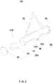
FIG. 1 is an isometric view of a first exemplary embodiment of a warning device for road safety. -
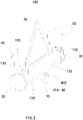
FIG.2 is an exploded view of the warning device ofFIG. 1 . -
FIG. 3 is an isometric view of a mobile state of the warning device ofFIG. 1 . -
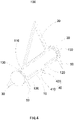
FIG. 4 is an isometric view of a supporting state of the warning device ofFIG. 1 . -
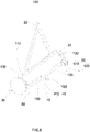
FIG. 5 is an isometric view of a second exemplary embodiment of the warning device in a mobile state. -
FIG. 6 is an isometric view of a supporting state of the warning device ofFIG.4 . - It will be appreciated that for simplicity and clarity of illustration, where appropriate, reference numerals have been repeated among the different figures to indicate corresponding or analogous elements. In addition, numerous specific details are set forth in order to provide a thorough understanding of the exemplary embodiments described herein. However, it will be understood by those of ordinary skill in the art that the exemplary embodiments described herein can be practiced without these specific details. In other instances, methods, procedures, and components have not been described in detail so as not to obscure the related relevant feature being described. The drawings are not necessarily to scale and the proportions of certain parts may be exaggerated to better illustrate details and features. The description is not to be considered as limiting the scope of the exemplary embodiments described herein. The scope of the the invention is defined by the appended claims.
- Several definitions that apply throughout this disclosure will now be presented.
- The term "substantially" is defined to be essentially conforming to the particular dimension, shape, or other feature that the term modifies, such that the component need not be exact. For example, "substantially cylindrical" means that the object resembles a cylinder, but can have one or more deviations from a true cylinder. The term "comprising" means "including, but not necessarily limited to"; it specifically indicates open-ended inclusion or membership in a so-described combination, group, series, and the like.
-
FIGS. 1 to 3 illustrate awarning device 100 in a first exemplary embodiment. - The
warning device 100 includes awarning sign 20 and apropelling mechanism 200, thewarning sign 20 is installed to an upper side of thedriving mechanism 200. The warning sign can be a warning triangle. - The driving mechanism includes a
base 10, adriving unit 60, twowheels 30, a plurality of supportingunits 50, and a plurality of driving members (not shown). - The
base 10 defines anaccommodating space 140, thedriving unit 60 is accommodated in theaccommodating space 140. - The two
wheels 30 are connected to the driving unit. The twowheels 30 are driven by the driving unit, so that thewarning device 100 is self-propelled. Thedriving unit 60 is a motor, the driving mechanism includes twowheels 30 connected to ends of thebase 10. - In at least one exemplary embodiment, the
driving mechanism 200 of thewarning device 100 further includes a standingunit 40. The standingunit 40 is connected to a lower side of a central portion of thebase 10. The standingunit 40 includes astanding bar 410 and a standingwheel 420, the standingwheel 420 is rotatably connected to thestanding bar 410. The standingbar 410 is connected to a lower side of a central portion of thebase 10, so that the standingwheel 420 and the twowheels 30 form a triangle, and thewarning device 100 is supported by the standingwheel 420 and the twowheels 30 so as to be upright when thewarning device 100 is self-propelled. - A plurality of supporting
units 50 are movably connected to thebase 10. A plurality of driving members are respectively connected to the supporting units. - Each of the supporting
units 50 is movable between a receiving position (as shown inFIG. 1 ), where the supportingunits 50 are received in thebase 10, and a supporting position (as shown inFIG. 4 ), where the supportingunits 50 support thedriving mechanism 200 in one location. Each of the supportingunits 50 is driven to move by a driving member. - Each of the supporting
units 50 includes a supporting pole and a connecting portion (not labeled). An end of the supporting pole is movably connected to thebase 10 through the connecting portion. - A plurality of receiving
slots 120 is defined on side surfaces of thebase 10, an end of the supporting pole is movably connected to an end portion of areceiving slot 120. When the supportingunit 50 is driven by the driving member to move to a receiving position, the supporting pole is received in areceiving slot 120. - In at least one exemplary embodiment, a plurality of
rotating slots 130 corresponding to the supporting units are defined on thebase 10. The supportingpole 50 is driven by the driven member to move out of thereceiving slot 120 and rotate in therotating slot 130 to the supporting position. - The
base 10 is a cylindrical case, thereceiving slots 120 can be axially parallel with the cylindrical case, and therotating slots 130 are along a radial direction of the cylindrical case. - In at least one exemplary embodiment, when the supporting poles are moved to the supporting position, the
base 10 is suspended. -
FIGS. 5 to 6 illustrate awarning device 100 in a second exemplary embodiment. The only difference between thewarning device 100 in the second exemplary embodiment and thewarning device 100 in the second exemplary embodiment is in the supporting pole. - The supporting pole in the second exemplary embodiment includes a first supporting
rod 510 and a second supportingrod 520. The second supportingrod 520 is rotatably connected to the first supportingrod 510, so that the first supportingrod 510 and the second supportingrod 520 are folded before being received in thereceiving slot 120. - Specifically, the second supporting
rod 520 is rotatable between a folding position, where the second supportingrod 520 is parallel with the first supportingrod 510, and a holding position, where the second supportingrod 520 is substantially perpendicular to the first supportingrod 510.
Claims (3)
- A self propelled warning device (100) comprising:a warning sign (20); anda driving mechanism (200) comprising:a cylindrical base (10) defining an accommodating space (140);a driving unit (60) accommodated in the accommodating space (140);two wheels (30) connected to the axial ends of the cylindrical base (10) such that they are parallel to the axial ends of the cylindrical base (10);said wheels (30) being connected to the driving unit (60);a standing unit (40) comprising a standing bar (410) and a standing wheel (420), the standing wheel (420) being rotatably connected to the standing bar (410), the standing bar (410) being connected to a lower side of a central portion of the base (10), so that the standing wheel (420) and the two wheels (30) form a triangle and the warning device (100) is supported by the standing wheel (420) and the two wheels (30) so as to be upright when the warning device (100) is self-propelled;wherein the warning sign (20) is installed to an upper side of the driving mechanism (200);the warning device (100) being characterized in that it further comprises:a plurality of supporting units (50) movably connected to the base (10); anda plurality of driving members respectively connected to the supporting units (50);wherein each of the supporting units (50) is movable between a receiving position, where the supporting units (50) are received in the base (10), and a supporting position, where the supporting units (50) support the driving mechanism (200) by being driven by the corresponding driving member;wherein each of the supporting units (50) comprises a supporting pole and a connecting portion, and an end of the supporting pole is movably connected to the base (10) through the connecting portion, a plurality of receiving slots (120) are defined on side surfaces of the base (10) such that they are axially parallel with the cylindrical base, an end of the supporting pole is movably connected to an end of the receiving slot (120); when the supporting unit (50) is driven by the driving member to move to the receiving position, the supporting pole is received in the corresponding receiving slot (120).
- The self propelled warning device (100) of claim 1, wherein when the supporting poles are moved to the supporting position, the base (10) is suspended.
- The self propelled warning device (100) of claim 1, wherein the supporting pole comprises a first supporting rod (510) and a second supporting rod (520) rotatably connected to the first supporting rod (510),
the second supporting rod (520) is rotatable between a folding position, where the second supporting rod (520) is parallel with the first supporting rod (510), and a holding position, where the second supporting rod (520) is substantially perpendicular to the first supporting rod (510).
Applications Claiming Priority (1)
| Application Number | Priority Date | Filing Date | Title |
|---|---|---|---|
| CN201710588317.5A CN109267510B (en) | 2017-07-18 | 2017-07-18 | Running gear and adopt this running gear's road warning device |
Publications (2)
| Publication Number | Publication Date |
|---|---|
| EP3432290A1 EP3432290A1 (en) | 2019-01-23 |
| EP3432290B1 true EP3432290B1 (en) | 2022-05-04 |
Family
ID=59997152
Family Applications (1)
| Application Number | Title | Priority Date | Filing Date |
|---|---|---|---|
| EP17193599.2A Active EP3432290B1 (en) | 2017-07-18 | 2017-09-27 | Warning device |
Country Status (3)
| Country | Link |
|---|---|
| US (1) | US10301785B2 (en) |
| EP (1) | EP3432290B1 (en) |
| CN (1) | CN109267510B (en) |
Families Citing this family (10)
| Publication number | Priority date | Publication date | Assignee | Title |
|---|---|---|---|---|
| CN109080532B (en) * | 2017-06-14 | 2022-01-21 | 鸿富锦精密电子(天津)有限公司 | Driving wheel mechanism and warning board adopting same |
| KR102224997B1 (en) * | 2017-12-11 | 2021-03-09 | 현대모비스 주식회사 | Safety tripod |
| TWI707311B (en) * | 2019-11-20 | 2020-10-11 | 正修學校財團法人正修科技大學 | Intelligent mobile system for warning devices |
| CN112937434A (en) * | 2019-12-10 | 2021-06-11 | 鸿富锦精密电子(天津)有限公司 | Tripod device |
| CN113291233B (en) * | 2020-02-21 | 2023-03-03 | 富联精密电子(天津)有限公司 | Support and warning board with same |
| CN114167849B (en) * | 2020-08-21 | 2023-12-08 | 富联精密电子(天津)有限公司 | Self-propelled triangle warning stand and its travel control method |
| CN112411415A (en) * | 2020-11-27 | 2021-02-26 | 江苏盐西高新城市建设有限公司 | Safety warning device for building engineering |
| CN112802352B (en) * | 2020-12-31 | 2022-02-01 | 无锡太机脑智能科技有限公司 | Method and device for realizing intelligent mobile traffic signal lamp |
| USD988896S1 (en) * | 2022-08-18 | 2023-06-13 | Shenzhen Thankshome Technology Co., Ltd. | Flat light |
| US20250242752A1 (en) * | 2024-01-30 | 2025-07-31 | Hector Guillermo Villavicencio | Foldable panel for facilitating spotting of on road hazards |
Citations (2)
| Publication number | Priority date | Publication date | Assignee | Title |
|---|---|---|---|---|
| CN203603083U (en) * | 2013-11-12 | 2014-05-21 | 永康市原野工业产品设计有限公司 | Remote control folding type road warning sign |
| DE102013104990A1 (en) * | 2013-05-15 | 2014-11-20 | Fraunhofer-Gesellschaft zur Förderung der angewandten Forschung e.V. | Emergency signaling device and a method for its production |
Family Cites Families (58)
| Publication number | Priority date | Publication date | Assignee | Title |
|---|---|---|---|---|
| US3933119A (en) * | 1972-07-19 | 1976-01-20 | Reflex Corporation Of Canada Limited | Triangular signalling device |
| BE873663A (en) * | 1979-01-23 | 1979-05-16 | Hartenstein Marcel | EARTHWORKING PROCESS FOR LAYING PIPELINES AND CABLES IN URBAN AREAS AND DEVICE INTENDED TO CARRY OUT THE PROCESS |
| US4403565A (en) * | 1981-03-11 | 1983-09-13 | Dominion Auto Accessories Limited | Emergency triangular road safety device |
| US4805550A (en) * | 1982-09-29 | 1989-02-21 | Ron Raczkowski | Safety triangle |
| US4613847A (en) * | 1983-08-08 | 1986-09-23 | Life Light Systems | Emergency signal |
| US4593265A (en) * | 1983-10-05 | 1986-06-03 | Lear Siegler, Inc. | Portable traffic control apparatus |
| US4543905A (en) * | 1983-11-02 | 1985-10-01 | Lear Siegler, Inc. | Portable traffic signalling apparatus and methods therefor |
| DE3807300C1 (en) * | 1988-03-05 | 1989-07-06 | Klaus Juergen 2000 Hamburg De Kiefer | |
| US5041813A (en) * | 1990-01-25 | 1991-08-20 | Chang Jih Cheng | "Automobile disabled" sign |
| SE9002448L (en) * | 1990-07-17 | 1992-01-18 | Ata Byy Markprod Ab | MARKING AND INFORMATION BOARD DEVICE |
| US5257020C1 (en) * | 1991-06-12 | 2002-08-13 | Fiber Optics Sales Co Inc | Variable message traffic signalling trailer |
| US5294138A (en) * | 1993-04-05 | 1994-03-15 | Yang Nan S | Traffic control cart |
| FR2717837B1 (en) * | 1994-03-25 | 1996-04-26 | Scrit | Improvements and Complements to removable Supports adaptable on Vibrated Concrete Slides. |
| GB2312457A (en) * | 1996-04-24 | 1997-10-29 | Beijing Success Electronic Co | Warning triangle |
| ES1039725Y (en) * | 1998-03-13 | 1999-06-01 | Fazanes Garcia Benito | HYDRAULIC MACHINE FOR NAILING POLES IMPROVED WITH AUTOMATIC BRAKE DEVICE AND HYDRAULIC CONTROL OPERATION. |
| CN2394953Y (en) * | 1999-09-03 | 2000-09-06 | 唐从武 | Warning sigh board for fault car |
| CN1267876A (en) * | 2000-04-25 | 2000-09-27 | 深圳市思博威实业发展有限公司 | Warning mark for malfunctioning vehicle |
| CN2421223Y (en) * | 2000-05-07 | 2001-02-28 | 孙世浩 | Lever type motorcycle stand |
| CA2328517A1 (en) * | 2000-12-14 | 2002-06-14 | Wws Leasing | Portable traffic light |
| US6374524B1 (en) * | 2001-01-08 | 2002-04-23 | Donald Capps | Portable traffic signaling and emergency response device |
| US6367494B1 (en) * | 2001-01-19 | 2002-04-09 | Benson Tung | Movable sunshade base |
| US6708643B2 (en) * | 2001-04-25 | 2004-03-23 | Tmc Safety Products, Inc. | Portable airport traffic barricade |
| CN2539768Y (en) * | 2002-04-17 | 2003-03-12 | 天津市神光新技术开发公司 | Triangular warming marker post |
| US6718670B2 (en) * | 2002-04-17 | 2004-04-13 | S.G. New Technology Development Company Tianjin | Triangular warning sign |
| US7158020B2 (en) * | 2002-09-10 | 2007-01-02 | Grady Jr James A | LED warning beacon |
| US7135990B2 (en) * | 2004-06-02 | 2006-11-14 | Signalisation Ver-Mac Inc. | Mobile traffic light |
| CA2519724C (en) * | 2004-09-16 | 2015-03-17 | Bradley S. Rohl | Portable traffic signalling device |
| US20060181432A1 (en) * | 2005-01-31 | 2006-08-17 | Monteith Samuel S | Light emitting reflective hazard alert unit |
| JP2005330801A (en) * | 2005-06-09 | 2005-12-02 | Furukawa Co Ltd | Road traffic regulation sign display device for vehicle installation |
| JP3118546U (en) * | 2005-10-20 | 2006-02-02 | 博 堀端 | Triangular plate with light emitting diode that can change signal shape |
| CN2883471Y (en) * | 2006-03-28 | 2007-03-28 | 罗俊仪 | Combined signboard |
| US20080129543A1 (en) | 2006-10-06 | 2008-06-05 | James Lee | Portable traffic signaling device |
| CN100569558C (en) * | 2008-05-07 | 2009-12-16 | 李政文 | Electric concealed type striking caution board for vehicle |
| CN201337172Y (en) * | 2008-12-30 | 2009-11-04 | 成都飞机设计研究所 | Auxiliary work bench |
| CN201849513U (en) * | 2010-08-26 | 2011-06-01 | 好孩子儿童用品有限公司 | Foldable child wheelbarrow |
| KR200468469Y1 (en) * | 2011-08-24 | 2013-08-20 | 한국도로공사 | Moving cart of traffic safety equipments |
| CN202226572U (en) * | 2011-09-03 | 2012-05-23 | 郑州科步科技有限公司 | Miniature remote control crane |
| US9601012B2 (en) | 2011-09-22 | 2017-03-21 | John Williams | Remote operated safety attendant |
| CN102880145B (en) | 2012-09-28 | 2016-02-03 | 三一汽车制造有限公司 | leg control system and engineering machinery |
| US9718401B2 (en) * | 2012-11-30 | 2017-08-01 | Tae Won Kim | Foldable emergency road sign |
| US8740267B1 (en) * | 2013-02-26 | 2014-06-03 | Tony C. Wilson | Deployable tanker truck barrier |
| CN203113234U (en) | 2013-03-19 | 2013-08-07 | 黄卫卿 | Triangular support warning board with throwing and recovering platform |
| US9242600B2 (en) * | 2013-11-27 | 2016-01-26 | Ahmad Omar Al Shalabi | Safety apparatus |
| CN103726455A (en) * | 2013-12-22 | 2014-04-16 | 张卫 | Umbrella-shaped warning device |
| CN203878487U (en) * | 2014-06-09 | 2014-10-15 | 孔炜晴 | Warning board |
| US9365987B2 (en) * | 2014-10-29 | 2016-06-14 | SafeTBots, LLC | Portable remote-controlled traffic and pedestrian control system |
| WO2016179627A1 (en) | 2015-05-13 | 2016-11-17 | Tas Ip Holdings Pty Ltd | A portable vehicle management system and a method for managing a vehicle |
| ES2602141B1 (en) | 2015-07-17 | 2017-11-22 | Stopvia Negocios, S.L. | ROAD SIGNALING EQUIPMENT |
| USD793890S1 (en) * | 2016-01-08 | 2017-08-08 | Shanghai Kazheng Energy Technology Co., Ltd. | Collapsible triangular warning frame |
| CN205408002U (en) | 2016-03-29 | 2016-07-27 | 龙倩茜 | All -round automatic device of shooing in scenic spot |
| TWI668677B (en) * | 2016-04-26 | 2019-08-11 | 新加坡商雲網科技新加坡有限公司 | Warning device |
| TWD181717S (en) * | 2016-04-26 | 2017-03-11 | 鴻海精密工業股份有限公司 | Vehicle warning device |
| CN105863686B (en) * | 2016-04-27 | 2018-10-30 | 高荣 | Inverted arch formwork hoisting walking carriage |
| CN105862624B (en) * | 2016-05-25 | 2017-11-24 | 舟山上橙文化创意有限公司 | A kind of road guardrail |
| CN107526391B (en) * | 2016-06-21 | 2020-05-08 | 鸿富锦精密电子(重庆)有限公司 | Display device |
| CN106592459A (en) * | 2016-08-30 | 2017-04-26 | 四川弘毅智慧知识产权运营有限公司 | Movable traffic indication arrow board |
| DE102016015008A1 (en) | 2016-12-16 | 2017-06-29 | Daimler Ag | Autonomous vehicle and method for issuing a warning in the event of a breakdown of an autonomous vehicle |
| CN109131067B (en) * | 2017-06-16 | 2021-11-19 | 鸿富锦精密电子(天津)有限公司 | Tripod self-propelled vehicle and obstacle avoidance method thereof |
-
2017
- 2017-07-18 CN CN201710588317.5A patent/CN109267510B/en active Active
- 2017-09-05 US US15/695,275 patent/US10301785B2/en active Active
- 2017-09-27 EP EP17193599.2A patent/EP3432290B1/en active Active
Patent Citations (2)
| Publication number | Priority date | Publication date | Assignee | Title |
|---|---|---|---|---|
| DE102013104990A1 (en) * | 2013-05-15 | 2014-11-20 | Fraunhofer-Gesellschaft zur Förderung der angewandten Forschung e.V. | Emergency signaling device and a method for its production |
| CN203603083U (en) * | 2013-11-12 | 2014-05-21 | 永康市原野工业产品设计有限公司 | Remote control folding type road warning sign |
Non-Patent Citations (5)
| Title |
|---|
| ANONYMOUS: "ALKO 590mm Drop Down Corner Steady + Big Foot", 14 April 2021 (2021-04-14), XP055795168, Retrieved from the Internet <URL:https://www.roadchief.co.nz/alko-590mm-drop-down-corner-steady-big-foot-77> [retrieved on 20210414] * |
| ANONYMOUS: "Corner Steadies", 8 June 2017 (2017-06-08), XP055795166, Retrieved from the Internet <URL:http://web.archive.org/web/20170608055607/https://www.alko.com.au/vehicle-technology-catalogue/corner-steadies/> [retrieved on 20210414] * |
| ANONYMOUS: "MAEDA MINI CRANES", 17 July 2017 (2017-07-17), XP055795197, Retrieved from the Internet <URL:http://web.archive.org/web/20170717115750/https://www.maeda-minicranes.com/> [retrieved on 20210414] * |
| ANONYMOUS: "SPIDER CRANE MC104C", CATALOG SPIDER CRANE MC104C, 2 August 2016 (2016-08-02), pages 1 - 2, XP055795646, Retrieved from the Internet <URL:https://www.maeda-minicranes.com/download/files/MC104C_Catalog.pdf> [retrieved on 20210415] * |
| ANONYMOUS: "SPIDER CRANE MC104C", MC104C | SPIDER CRANE | MAEDA MINI CRANES, 14 April 2021 (2021-04-14), JP, pages 1 - 22, XP055795647, Retrieved from the Internet <URL:https://www.maeda-minicranes.com/products/spider-cranes/mc104c/> [retrieved on 20210415] * |
Also Published As
| Publication number | Publication date |
|---|---|
| CN109267510B (en) | 2021-10-01 |
| EP3432290A1 (en) | 2019-01-23 |
| US20190024332A1 (en) | 2019-01-24 |
| US10301785B2 (en) | 2019-05-28 |
| CN109267510A (en) | 2019-01-25 |
Similar Documents
| Publication | Publication Date | Title |
|---|---|---|
| US10301785B2 (en) | Driving mechanism and warning device using the same | |
| EP3419007A1 (en) | Warning device | |
| CN201865064U (en) | Prompting device for traffic management | |
| JP6895324B2 (en) | Steering device | |
| US11981554B2 (en) | Conveyor for moving four-wheeled vehicles | |
| EP2692687A1 (en) | Driving aid device and an industrial truck with driving aid device | |
| EP3538406B1 (en) | A carriage for moving a wheeled object | |
| CN104827448A (en) | Tool for assembling instrument board sub-assembly | |
| CN105799666A (en) | Automobile transverse movement wheel bracket | |
| CN110444853B (en) | Replaceable masts for emergency communication vehicles | |
| CN111629964A (en) | Unmanned plane | |
| US20180363255A1 (en) | Driving mechanism and self-propelled warning device using the same | |
| EP3366518B1 (en) | Vehicle emergency safety device using selfie stick | |
| HRP20190969T1 (en) | UNDERCARRIAGE LAND VEHICLE FRAME OR UGV | |
| CN106660763B (en) | frame support | |
| CN204184861U (en) | Skid and skid group | |
| CN105313851A (en) | Trailer for moving saloon car | |
| CN205554158U (en) | Wheel bracket of car lateral shifting device | |
| CN203996158U (en) | Trailer for mobile car | |
| CN210027913U (en) | Unmanned aerial vehicle | |
| DE102021130801A1 (en) | Loading robot and method for operating a loading robot | |
| CN221608692U (en) | Traffic anticollision safety barrier | |
| CN221142571U (en) | Folding refuse horse | |
| CN210941830U (en) | Expansion type logistics trolley chassis | |
| CN117026866B (en) | Forced stop device for large-sized vehicle |
Legal Events
| Date | Code | Title | Description |
|---|---|---|---|
| PUAI | Public reference made under article 153(3) epc to a published international application that has entered the european phase |
Free format text: ORIGINAL CODE: 0009012 |
|
| STAA | Information on the status of an ep patent application or granted ep patent |
Free format text: STATUS: REQUEST FOR EXAMINATION WAS MADE |
|
| 17P | Request for examination filed |
Effective date: 20180529 |
|
| AK | Designated contracting states |
Kind code of ref document: A1 Designated state(s): AL AT BE BG CH CY CZ DE DK EE ES FI FR GB GR HR HU IE IS IT LI LT LU LV MC MK MT NL NO PL PT RO RS SE SI SK SM TR |
|
| AX | Request for extension of the european patent |
Extension state: BA ME |
|
| STAA | Information on the status of an ep patent application or granted ep patent |
Free format text: STATUS: EXAMINATION IS IN PROGRESS |
|
| 17Q | First examination report despatched |
Effective date: 20190607 |
|
| RIC1 | Information provided on ipc code assigned before grant |
Ipc: B60Q 7/00 20060101ALI20211122BHEP Ipc: E01F 9/688 20160101ALI20211122BHEP Ipc: G08G 1/0955 20060101AFI20211122BHEP |
|
| GRAP | Despatch of communication of intention to grant a patent |
Free format text: ORIGINAL CODE: EPIDOSNIGR1 |
|
| STAA | Information on the status of an ep patent application or granted ep patent |
Free format text: STATUS: GRANT OF PATENT IS INTENDED |
|
| INTG | Intention to grant announced |
Effective date: 20220107 |
|
| GRAS | Grant fee paid |
Free format text: ORIGINAL CODE: EPIDOSNIGR3 |
|
| GRAA | (expected) grant |
Free format text: ORIGINAL CODE: 0009210 |
|
| STAA | Information on the status of an ep patent application or granted ep patent |
Free format text: STATUS: THE PATENT HAS BEEN GRANTED |
|
| AK | Designated contracting states |
Kind code of ref document: B1 Designated state(s): AL AT BE BG CH CY CZ DE DK EE ES FI FR GB GR HR HU IE IS IT LI LT LU LV MC MK MT NL NO PL PT RO RS SE SI SK SM TR |
|
| REG | Reference to a national code |
Ref country code: GB Ref legal event code: FG4D |
|
| REG | Reference to a national code |
Ref country code: CH Ref legal event code: EP |
|
| REG | Reference to a national code |
Ref country code: AT Ref legal event code: REF Ref document number: 1489943 Country of ref document: AT Kind code of ref document: T Effective date: 20220515 |
|
| REG | Reference to a national code |
Ref country code: IE Ref legal event code: FG4D Ref country code: DE Ref legal event code: R096 Ref document number: 602017056815 Country of ref document: DE |
|
| REG | Reference to a national code |
Ref country code: LT Ref legal event code: MG9D |
|
| REG | Reference to a national code |
Ref country code: NL Ref legal event code: MP Effective date: 20220504 |
|
| REG | Reference to a national code |
Ref country code: AT Ref legal event code: MK05 Ref document number: 1489943 Country of ref document: AT Kind code of ref document: T Effective date: 20220504 |
|
| PG25 | Lapsed in a contracting state [announced via postgrant information from national office to epo] |
Ref country code: SE Free format text: LAPSE BECAUSE OF FAILURE TO SUBMIT A TRANSLATION OF THE DESCRIPTION OR TO PAY THE FEE WITHIN THE PRESCRIBED TIME-LIMIT Effective date: 20220504 Ref country code: PT Free format text: LAPSE BECAUSE OF FAILURE TO SUBMIT A TRANSLATION OF THE DESCRIPTION OR TO PAY THE FEE WITHIN THE PRESCRIBED TIME-LIMIT Effective date: 20220905 Ref country code: NO Free format text: LAPSE BECAUSE OF FAILURE TO SUBMIT A TRANSLATION OF THE DESCRIPTION OR TO PAY THE FEE WITHIN THE PRESCRIBED TIME-LIMIT Effective date: 20220804 Ref country code: NL Free format text: LAPSE BECAUSE OF FAILURE TO SUBMIT A TRANSLATION OF THE DESCRIPTION OR TO PAY THE FEE WITHIN THE PRESCRIBED TIME-LIMIT Effective date: 20220504 Ref country code: LT Free format text: LAPSE BECAUSE OF FAILURE TO SUBMIT A TRANSLATION OF THE DESCRIPTION OR TO PAY THE FEE WITHIN THE PRESCRIBED TIME-LIMIT Effective date: 20220504 Ref country code: HR Free format text: LAPSE BECAUSE OF FAILURE TO SUBMIT A TRANSLATION OF THE DESCRIPTION OR TO PAY THE FEE WITHIN THE PRESCRIBED TIME-LIMIT Effective date: 20220504 Ref country code: GR Free format text: LAPSE BECAUSE OF FAILURE TO SUBMIT A TRANSLATION OF THE DESCRIPTION OR TO PAY THE FEE WITHIN THE PRESCRIBED TIME-LIMIT Effective date: 20220805 Ref country code: FI Free format text: LAPSE BECAUSE OF FAILURE TO SUBMIT A TRANSLATION OF THE DESCRIPTION OR TO PAY THE FEE WITHIN THE PRESCRIBED TIME-LIMIT Effective date: 20220504 Ref country code: ES Free format text: LAPSE BECAUSE OF FAILURE TO SUBMIT A TRANSLATION OF THE DESCRIPTION OR TO PAY THE FEE WITHIN THE PRESCRIBED TIME-LIMIT Effective date: 20220504 Ref country code: BG Free format text: LAPSE BECAUSE OF FAILURE TO SUBMIT A TRANSLATION OF THE DESCRIPTION OR TO PAY THE FEE WITHIN THE PRESCRIBED TIME-LIMIT Effective date: 20220804 Ref country code: AT Free format text: LAPSE BECAUSE OF FAILURE TO SUBMIT A TRANSLATION OF THE DESCRIPTION OR TO PAY THE FEE WITHIN THE PRESCRIBED TIME-LIMIT Effective date: 20220504 |
|
| PG25 | Lapsed in a contracting state [announced via postgrant information from national office to epo] |
Ref country code: RS Free format text: LAPSE BECAUSE OF FAILURE TO SUBMIT A TRANSLATION OF THE DESCRIPTION OR TO PAY THE FEE WITHIN THE PRESCRIBED TIME-LIMIT Effective date: 20220504 Ref country code: PL Free format text: LAPSE BECAUSE OF FAILURE TO SUBMIT A TRANSLATION OF THE DESCRIPTION OR TO PAY THE FEE WITHIN THE PRESCRIBED TIME-LIMIT Effective date: 20220504 Ref country code: LV Free format text: LAPSE BECAUSE OF FAILURE TO SUBMIT A TRANSLATION OF THE DESCRIPTION OR TO PAY THE FEE WITHIN THE PRESCRIBED TIME-LIMIT Effective date: 20220504 Ref country code: IS Free format text: LAPSE BECAUSE OF FAILURE TO SUBMIT A TRANSLATION OF THE DESCRIPTION OR TO PAY THE FEE WITHIN THE PRESCRIBED TIME-LIMIT Effective date: 20220904 |
|
| PG25 | Lapsed in a contracting state [announced via postgrant information from national office to epo] |
Ref country code: SM Free format text: LAPSE BECAUSE OF FAILURE TO SUBMIT A TRANSLATION OF THE DESCRIPTION OR TO PAY THE FEE WITHIN THE PRESCRIBED TIME-LIMIT Effective date: 20220504 Ref country code: SK Free format text: LAPSE BECAUSE OF FAILURE TO SUBMIT A TRANSLATION OF THE DESCRIPTION OR TO PAY THE FEE WITHIN THE PRESCRIBED TIME-LIMIT Effective date: 20220504 Ref country code: RO Free format text: LAPSE BECAUSE OF FAILURE TO SUBMIT A TRANSLATION OF THE DESCRIPTION OR TO PAY THE FEE WITHIN THE PRESCRIBED TIME-LIMIT Effective date: 20220504 Ref country code: EE Free format text: LAPSE BECAUSE OF FAILURE TO SUBMIT A TRANSLATION OF THE DESCRIPTION OR TO PAY THE FEE WITHIN THE PRESCRIBED TIME-LIMIT Effective date: 20220504 Ref country code: DK Free format text: LAPSE BECAUSE OF FAILURE TO SUBMIT A TRANSLATION OF THE DESCRIPTION OR TO PAY THE FEE WITHIN THE PRESCRIBED TIME-LIMIT Effective date: 20220504 Ref country code: CZ Free format text: LAPSE BECAUSE OF FAILURE TO SUBMIT A TRANSLATION OF THE DESCRIPTION OR TO PAY THE FEE WITHIN THE PRESCRIBED TIME-LIMIT Effective date: 20220504 |
|
| REG | Reference to a national code |
Ref country code: DE Ref legal event code: R097 Ref document number: 602017056815 Country of ref document: DE |
|
| REG | Reference to a national code |
Ref country code: DE Ref legal event code: R081 Ref document number: 602017056815 Country of ref document: DE Owner name: FULIAN PRECISION ELECTRONICS (TIANJIN) CO., LT, CN Free format text: FORMER OWNER: HONGFUJIN PRECISION ELECTRONICS (TIANJIN) CO., LTD., TIANJIN, CN |
|
| PLBE | No opposition filed within time limit |
Free format text: ORIGINAL CODE: 0009261 |
|
| STAA | Information on the status of an ep patent application or granted ep patent |
Free format text: STATUS: NO OPPOSITION FILED WITHIN TIME LIMIT |
|
| PG25 | Lapsed in a contracting state [announced via postgrant information from national office to epo] |
Ref country code: AL Free format text: LAPSE BECAUSE OF FAILURE TO SUBMIT A TRANSLATION OF THE DESCRIPTION OR TO PAY THE FEE WITHIN THE PRESCRIBED TIME-LIMIT Effective date: 20220504 |
|
| 26N | No opposition filed |
Effective date: 20230207 |
|
| PG25 | Lapsed in a contracting state [announced via postgrant information from national office to epo] |
Ref country code: MC Free format text: LAPSE BECAUSE OF FAILURE TO SUBMIT A TRANSLATION OF THE DESCRIPTION OR TO PAY THE FEE WITHIN THE PRESCRIBED TIME-LIMIT Effective date: 20220504 |
|
| REG | Reference to a national code |
Ref country code: CH Ref legal event code: PL |
|
| REG | Reference to a national code |
Ref country code: BE Ref legal event code: MM Effective date: 20220930 |
|
| PG25 | Lapsed in a contracting state [announced via postgrant information from national office to epo] |
Ref country code: SI Free format text: LAPSE BECAUSE OF FAILURE TO SUBMIT A TRANSLATION OF THE DESCRIPTION OR TO PAY THE FEE WITHIN THE PRESCRIBED TIME-LIMIT Effective date: 20220504 |
|
| PG25 | Lapsed in a contracting state [announced via postgrant information from national office to epo] |
Ref country code: LU Free format text: LAPSE BECAUSE OF NON-PAYMENT OF DUE FEES Effective date: 20220927 |
|
| PG25 | Lapsed in a contracting state [announced via postgrant information from national office to epo] |
Ref country code: LI Free format text: LAPSE BECAUSE OF NON-PAYMENT OF DUE FEES Effective date: 20220930 Ref country code: IE Free format text: LAPSE BECAUSE OF NON-PAYMENT OF DUE FEES Effective date: 20220927 Ref country code: CH Free format text: LAPSE BECAUSE OF NON-PAYMENT OF DUE FEES Effective date: 20220930 |
|
| PG25 | Lapsed in a contracting state [announced via postgrant information from national office to epo] |
Ref country code: BE Free format text: LAPSE BECAUSE OF NON-PAYMENT OF DUE FEES Effective date: 20220930 |
|
| PG25 | Lapsed in a contracting state [announced via postgrant information from national office to epo] |
Ref country code: IT Free format text: LAPSE BECAUSE OF FAILURE TO SUBMIT A TRANSLATION OF THE DESCRIPTION OR TO PAY THE FEE WITHIN THE PRESCRIBED TIME-LIMIT Effective date: 20220504 |
|
| PG25 | Lapsed in a contracting state [announced via postgrant information from national office to epo] |
Ref country code: HU Free format text: LAPSE BECAUSE OF FAILURE TO SUBMIT A TRANSLATION OF THE DESCRIPTION OR TO PAY THE FEE WITHIN THE PRESCRIBED TIME-LIMIT; INVALID AB INITIO Effective date: 20170927 |
|
| PG25 | Lapsed in a contracting state [announced via postgrant information from national office to epo] |
Ref country code: CY Free format text: LAPSE BECAUSE OF FAILURE TO SUBMIT A TRANSLATION OF THE DESCRIPTION OR TO PAY THE FEE WITHIN THE PRESCRIBED TIME-LIMIT Effective date: 20220504 |
|
| PG25 | Lapsed in a contracting state [announced via postgrant information from national office to epo] |
Ref country code: MK Free format text: LAPSE BECAUSE OF FAILURE TO SUBMIT A TRANSLATION OF THE DESCRIPTION OR TO PAY THE FEE WITHIN THE PRESCRIBED TIME-LIMIT Effective date: 20220504 |
|
| PG25 | Lapsed in a contracting state [announced via postgrant information from national office to epo] |
Ref country code: MT Free format text: LAPSE BECAUSE OF FAILURE TO SUBMIT A TRANSLATION OF THE DESCRIPTION OR TO PAY THE FEE WITHIN THE PRESCRIBED TIME-LIMIT Effective date: 20220504 |
|
| PG25 | Lapsed in a contracting state [announced via postgrant information from national office to epo] |
Ref country code: BG Free format text: LAPSE BECAUSE OF FAILURE TO SUBMIT A TRANSLATION OF THE DESCRIPTION OR TO PAY THE FEE WITHIN THE PRESCRIBED TIME-LIMIT Effective date: 20220504 |
|
| PG25 | Lapsed in a contracting state [announced via postgrant information from national office to epo] |
Ref country code: BG Free format text: LAPSE BECAUSE OF FAILURE TO SUBMIT A TRANSLATION OF THE DESCRIPTION OR TO PAY THE FEE WITHIN THE PRESCRIBED TIME-LIMIT Effective date: 20220504 |
|
| PGFP | Annual fee paid to national office [announced via postgrant information from national office to epo] |
Ref country code: DE Payment date: 20250916 Year of fee payment: 9 |
|
| PGFP | Annual fee paid to national office [announced via postgrant information from national office to epo] |
Ref country code: GB Payment date: 20250919 Year of fee payment: 9 |
|
| PGFP | Annual fee paid to national office [announced via postgrant information from national office to epo] |
Ref country code: FR Payment date: 20250929 Year of fee payment: 9 |
|
| PG25 | Lapsed in a contracting state [announced via postgrant information from national office to epo] |
Ref country code: TR Free format text: LAPSE BECAUSE OF FAILURE TO SUBMIT A TRANSLATION OF THE DESCRIPTION OR TO PAY THE FEE WITHIN THE PRESCRIBED TIME-LIMIT Effective date: 20220504 |