EP3432109B1 - Système et procédé de réglage automatique d'un tracteur agricole et outil - Google Patents
Système et procédé de réglage automatique d'un tracteur agricole et outil Download PDFInfo
- Publication number
- EP3432109B1 EP3432109B1 EP18183682.6A EP18183682A EP3432109B1 EP 3432109 B1 EP3432109 B1 EP 3432109B1 EP 18183682 A EP18183682 A EP 18183682A EP 3432109 B1 EP3432109 B1 EP 3432109B1
- Authority
- EP
- European Patent Office
- Prior art keywords
- vehicle
- parameters
- output
- set forth
- control
- Prior art date
- Legal status (The legal status is an assumption and is not a legal conclusion. Google has not performed a legal analysis and makes no representation as to the accuracy of the status listed.)
- Active
Links
- 238000000034 method Methods 0.000 title claims description 30
- 230000026676 system process Effects 0.000 claims description 14
- 238000005259 measurement Methods 0.000 description 8
- 230000008569 process Effects 0.000 description 8
- 230000003044 adaptive effect Effects 0.000 description 6
- 101100063070 Bacillus subtilis (strain 168) degA gene Proteins 0.000 description 4
- 238000013461 design Methods 0.000 description 4
- 238000010586 diagram Methods 0.000 description 4
- 239000002689 soil Substances 0.000 description 4
- 230000001133 acceleration Effects 0.000 description 3
- 230000008859 change Effects 0.000 description 3
- 238000004590 computer program Methods 0.000 description 3
- 238000013016 damping Methods 0.000 description 3
- 230000004044 response Effects 0.000 description 3
- 230000006399 behavior Effects 0.000 description 2
- 238000004891 communication Methods 0.000 description 2
- 230000007423 decrease Effects 0.000 description 2
- 230000006870 function Effects 0.000 description 2
- 230000005484 gravity Effects 0.000 description 2
- 230000003287 optical effect Effects 0.000 description 2
- 230000006978 adaptation Effects 0.000 description 1
- 230000008901 benefit Effects 0.000 description 1
- 101150083941 degS gene Proteins 0.000 description 1
- 238000009313 farming Methods 0.000 description 1
- 239000007788 liquid Substances 0.000 description 1
- 239000013307 optical fiber Substances 0.000 description 1
- 238000005070 sampling Methods 0.000 description 1
- 239000004065 semiconductor Substances 0.000 description 1
- 230000000087 stabilizing effect Effects 0.000 description 1
- 238000012546 transfer Methods 0.000 description 1
Images


Classifications
-
- G—PHYSICS
- G05—CONTROLLING; REGULATING
- G05D—SYSTEMS FOR CONTROLLING OR REGULATING NON-ELECTRIC VARIABLES
- G05D1/00—Control of position, course, altitude or attitude of land, water, air or space vehicles, e.g. using automatic pilots
- G05D1/0088—Control of position, course, altitude or attitude of land, water, air or space vehicles, e.g. using automatic pilots characterized by the autonomous decision making process, e.g. artificial intelligence, predefined behaviours
-
- A—HUMAN NECESSITIES
- A01—AGRICULTURE; FORESTRY; ANIMAL HUSBANDRY; HUNTING; TRAPPING; FISHING
- A01B—SOIL WORKING IN AGRICULTURE OR FORESTRY; PARTS, DETAILS, OR ACCESSORIES OF AGRICULTURAL MACHINES OR IMPLEMENTS, IN GENERAL
- A01B69/00—Steering of agricultural machines or implements; Guiding agricultural machines or implements on a desired track
- A01B69/007—Steering or guiding of agricultural vehicles, e.g. steering of the tractor to keep the plough in the furrow
- A01B69/008—Steering or guiding of agricultural vehicles, e.g. steering of the tractor to keep the plough in the furrow automatic
-
- G—PHYSICS
- G05—CONTROLLING; REGULATING
- G05D—SYSTEMS FOR CONTROLLING OR REGULATING NON-ELECTRIC VARIABLES
- G05D1/00—Control of position, course, altitude or attitude of land, water, air or space vehicles, e.g. using automatic pilots
- G05D1/02—Control of position or course in two dimensions
- G05D1/021—Control of position or course in two dimensions specially adapted to land vehicles
- G05D1/0212—Control of position or course in two dimensions specially adapted to land vehicles with means for defining a desired trajectory
Definitions
- Efforts to automate or semi-automate farming operations have increased considerably over recent years. Such efforts serve not only to reduce operating costs but also improve working conditions for operators and reduce operator error, enabling gains in operational efficiency and yield.
- agricultural machines may employ an automated guidance system to reduce operator fatigue and costs.
- Automated guidance systems enable traversal through a field based on predetermined lanes which are tracked by comparison with continually updated positional coordinates to enable the guidance system to generate an output for the steering system.
- One of the difficulties of implementing automated guidance systems for off-road vehicles is that the dynamics of the off-road vehicles are constantly changing. This is due to several factors such as soil irregularities and changes in the vehicle driving speed and hitch load. This makes the design and implementation of a controller a difficult and time-consuming task, since finding a set of controller parameters for every vehicle type and operating situation is nearly impossible.
- look-up tables that are predetermined by the vehicle manufacturer and are used in a predetermined controller strategy (e.g. a proportional ("P") or "proportional-integral-derivative ("PID”) controller) to generate the signals for steering the vehicle.
- P proportional
- PID proportional-integral-derivative
- these pre-defined look-up tables require a substantial amount of time and resources to create and have limited adaptability to changing working conditions (such as, for example, attached implements).
- ordinary machine operators are generally not able to tune or adjust the behavior of automated guidance systems, such adjusting generally requires skills such as those possessed by an engineer involved in the design of the automated guidance system.
- Embodiments of the present invention solve the above-described and other problems and limitations by providing an off-road vehicle system having a more efficient adaptive controller that saves time in its implementation and parameter tuning and accommodates changes of the vehicle's dynamics in real time.
- the self-tuning regulator includes minimum-degree pole placement based on a real-time/online identification of the vehicle dynamics plus a real-time/online computation of control parameters.
- a linear second order system can be used as a closed-loop reference model and thus the closed-loop yaw rate (output) will behave essentially the same regardless of the changes in the soil conditions and hitch load.
- the linearity also makes the implementation of the controller in an embedded system less complex and less time consuming. When this method is used to control vehicle yaw rate, it may also use a gain scheduler to control lateral position.
- a look-up table of the lateral position will need few sets of proportional, integral, and derivative (PID) parameters. Since the identification is based on a general second order system, this method can be applied to different steering systems such as skid-steering, 4W-steering, and articulated steering. When this method is used to control lateral position directly, no look-up table or PID parameters are needed since the RST parameters will cover the control of the lateral position (output).
- An off-road vehicle constructed according to an embodiment of the invention comprises a chassis, a plurality of ground-engaging elements for supporting the chassis on a ground surface and propelling the vehicle along the ground surface, a power source for driving movement of at least one of the ground-engaging elements, and a control system configured to provide automatic guidance for the vehicle by automatically steering the vehicle via at least one of the plurality of ground-engaging elements.
- the control system is configured to apply an estimator to determine a plurality of system process parameters, the estimator using at least one value generated by the control system and at least one measured vehicle output to determine the plurality of system process parameters in real time during vehicle operation, determine a reference model based at least in part on user input, determine a plurality of control parameters using the process parameters and the reference model, determine a guidance input according to the control parameters, a setpoint of a desired output, and a previously measured output, and use the guidance input to automatically guide the vehicle.
- the estimator is configured to determine the plurality of system process parameters such that the control system automatically guides the vehicle so that the vehicle responds substantially in the same manner across different ground surface conditions, hitch forces and vehicle velocities.
- a method of controlling an off-road vehicle comprises applying an estimator to determine a plurality of system process parameters, the estimator using at least one value generated by a vehicle control system and at least one measured vehicle output to determine the plurality of system process parameters in real time during vehicle operation, determining a reference model based at least in part on user input, determining a plurality of control parameters using the process parameters and the reference model, determining a guidance input according to the control parameters, a setpoint of a desired output, and a previously measured output, and using the guidance input to automatically steering the vehicle, the estimator being configured to determine the plurality of system process parameters such that the automatically steering the vehicle occurs so that the vehicle responds substantially in the same manner across different ground surface conditions, hitch forces and vehicle velocities.
- the invention can also be used for further vehicle systems such as self-propelled agricultural machines such as Combines or autonomous vehicles such agricultural robots .
- the vehicle system 10 may include a tractor 12 or other off-road towing device and a towed implement 14.
- the implement 14 may be a plow, a planter, an irrigator, a baler, a harvester, or the like.
- the vehicle system 10 also includes or is controlled via a control system 16 having a controller 18 and a plurality of sensors 20.
- the controller 18 may include computing components such as a processor, a memory, a user interface, a power component, and a communication component for communicating with remote servers or computing systems 22, global navigation satellite systems (GNSS) 24, and/or user input devices 26 over a wireless network.
- the controller 18 may be integrated with the vehicle system 10 or may be an off-site system configured to control the vehicle system 10 remotely.
- the controller 18 may run computer programs preferably comprising ordered listings of executable instructions for implementing logical functions in the controller 18.
- the computer programs can be stored and/or embodied in or on any computer-readable medium for use by or in connection with an instruction execution system, apparatus, or device, such as a computer-based system, processor-containing system, or other system that can fetch the instructions from the instruction execution system, apparatus, or device, and execute the instructions.
- a "computer-readable medium" can be any means that can contain, store, communicate, propagate or transport the program for use by or in connection with the instruction execution system, apparatus, or device.
- the computer-readable medium can be, for example, but is not limited to, an electronic, magnetic, optical, electromagnetic, infrared, or semi-conductor system, apparatus, device, or propagation medium. More specific, although not inclusive, examples of the computer-readable medium would include the following: an electrical connection having one or more wires, a portable computer diskette, a random access memory (RAM), a read-only memory (ROM), an erasable, programmable, read-only memory (EPROM or Flash memory), an optical fiber, and a portable compact disk read-only memory (CDROM).
- the computer-readable medium may be one or more components incorporated into or in remote communication with the controller 18.
- the memory may include, for example, removable and non-removable memory elements such as RAM, ROM, flash, magnetic, optical, USB memory devices, and/or other conventional memory elements.
- the memory may store various data associated with the controller 18, such as the computer program and code segments mentioned above, or other data for performing the steps described herein.
- the sensors 20 may be any type of sensing devices such as an inertial measurement units (IMU), VarioGuide/real-time-kinematic (RTK) sensors, GNSS sensors, and the like.
- the computing systems 22 may be remote servers, desktop computing stations, and the like.
- the GNSS satellite systems 24 may be any kind of global positioning satellites such as GPS or GLONASS.
- the user input devices 26 may be desktop computers, laptops, tablets, smartphones, and the like.
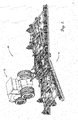
- the vehicle system 10 can be represented as a 3-wheeled tractor-implement bicycle model.
- ⁇ is the yaw rate around the center of gravity
- ⁇ is the steering angle
- ⁇ r and ⁇ h are the front, rear and hitch slip angles, respectively.
- the distances from the front and rear axle to the center of gravity are a and b, respectively
- c is the distance from the rear axle to the hitch.
- Lateral forces at front, rear, and hitch tires are represented by F f , F r and F h , respectively, and by assuming constant longitudinal velocity ( V x ), the longitudinal acceleration is null and the longitudinal forces are neglected. Therefore, the yaw rate dynamics of the model represented by figure 1 , can be expressed by analyzing the simplified lateral dynamics with equation (1).
- C ⁇ f , C ⁇ r and C ⁇ h are the front, rear and hitch cornering stiffness and vary depending on the conditions and types of soil.
- the vehicle system 10 should respond essentially the same regardless of the changes to soil conditions or velocity.
- an adaptive/self-tuning procedure i.e., self-tuning regulator
- self-tuning regulator can be used to change the control parameters in such a way that the vehicle system 10 has essentially the same closed-loop response.
- the self-tuning regulator will be described followed by its application to the vehicle system 10.
- the self-tuning regulator is shown.
- a vehicle yaw rate is measured via one of the sensors 20, as shown in block 100.
- a generated control signal including a desired steering angle is used, as shown in block 102.
- An estimator (see equations (7), (8), and (9) below) is then applied, as shown in block 104.
- a desired reference model is then found via equation (12), as shown in block 106.
- Various user input parameters may be used to find the desired reference model, as shown in block 108.
- the user input may be limited to natural frequency ⁇ n and damping ratio ⁇ , values which can be easily detected by the user without engineering knowledge.
- the natural frequency ⁇ n is a value representing the time needed to arrive at the desired path in case of a deviation.
- the damping ratio influences overshooting. Generally both values define whether the behavior of the vehicle is more aggressive or less aggressive.
- controller parameters are found via equation (16), as shown in block 110.
- measurements are updated as shown in block 112.
- a new control signal is generated according to equation (17), as shown in block 114.
- a reference input specifically a yaw rate set point, may be utilized in this step, as shown in block 116.
- a desired steering angle is then applied to the tractor 12, as shown in block 118.
- the process of block 200 can be represented by equation (7), which corresponds to a digital form of the equations found previously for the representation of the vehicle system 10 (equations (5) and (6)).
- the "estimator" of block 202 represented by equation (8), can be used to find the parameters a 1 , a 2 , b 0 and b 1 on the go by measuring u (desired curvature [1/km] or desired steering angle [deg]) and y (yaw rate).
- the controller design of block 204 determines the parameters R, T and S of the controller represented by equation (11) and Block 206, based on the reference model of equation (12), to obtain a desired closed-loop response.
- MDPP minimum-degree pole placement
- FIG. 6B shows a row of desired set points ( ⁇ desired) to be followed by the vehicle system 10 driving at 3.6[k/h].
- a cornering stiffness of 300[ N / deg ] at the hitch represents an implement of relatively low load.
- the yaw rate of the vehicle is measured ( ⁇ . measured ) and used to identify the vehicle system 10 with the aid of equation (8).
- the identified parameters are used iteratively to calculate the new control parameters R, T and S (Eq. (16)). This can be noticed in the first seconds where the measured and the identified lines present some abrupt changes until the identified parameters converge and the correct control parameters are calculated stabilizing the system.
- FIG. 6A presents the form of the control signal ⁇ [ deg ]) applied to the steering system of the tractor 12 that results in the data of FIG. 6B . It can be observed that small steering angles (2 to 8 degrees) are enough to bring the tractor 12 to the desired yaw rates.
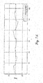
- FIGS. 7A and 7B shows the same tractor 12 driving at higher speed and having bigger load at the hitch. Here, the steering input to be applied has to be bigger to compensate for those changes.
- FIGS. 7A-8B show that as the cornering stiffness increases, so does the amplitude of the steering angle. Also, with higher values of cornering stiffness, the adaptive steering input increases gradually as a ramp to maintain the same yaw rate, whereas at lower values the input takes more the form of a step. As a result, this shows that the procedure adapts the control signal quite well to the different velocities and hitch cornering stiffness. It is very important to mention, that the adaptation depends on the identified system. For instance, FIGS. 8A and 8B show that the measured signal follows the identified signal quite well. Nevertheless, the identified signal deviates from the original one producing a steady state error.
- FIG. 9 a flow diagram to control the lateral position or "Xtrack" is shown.
- the process of controlling the lateral position is similar to controlling the yaw rate of FIG. 4 .
- the set point uc represents the desired lateral position (normally 0 if the vehicle stays on the lane), and the output y represents the measured lateral positions.
- the control signal u will still be the desired curvature in [1/ km ] (the same as the one used for the yaw rate control) or the desired steering angle in [deg].
- the estimator will be using the desired steering signal and the measured lateral position as inputs for the identification.
- a vehicle lateral position is measured via one of the sensors 20, as shown in block 300.
- a generated control signal including a desired steering angle is used, as shown in block 302.
- An estimator (equations (7), (8), and (9)) is then applied, as shown in block 304.
- a desired reference model is then found via equation (12), as shown in block 306.
- controller parameters are found via equation (16), as shown in block 310.
- measurements are updated as shown in block 312.
- a new control signal is generated according to equation (17), as shown in block 314.
- a reference input specifically a lateral position set point, may be utilized in this step, as shown in block 316.
- a desired steering angle is then applied to the tractor 12, as shown in block 318.
- embodiments of the invention set forth herein are operable to automatically guide a vehicle in such a way that it can automatically and dynamically adapt to different operating conditions in real time and without user input such that the vehicle responds or behaves in substantially the same manner regardless of the operating conditions, even if those operating conditions change during operation of the vehicle.
- Different operating conditions may include virtually anything that would cause the vehicle to respond or behave differently under the same machine settings such as steering angle or motive power.
- Operating conditions may include, without limitation, implements attached to the vehicle (or lack thereof), fill levels of tanks or bins on the vehicle or an implement, and ground and surface conditions including hardness, smoothness and slope of the ground.
- a tractor operating without an implement may follow a first curve with a first radius when the wheels are set at a given steering angle.
- an implement When an implement is attached to the tractor it may follow a second curve with a second radius when the wheels are set at the same steering angle.
- Operating conditions may change during a single operation, such as when an applicator tank on an implement towed by a tractor is gradually depleted of liquid during an application operation.
- the weight of the implement also decreases and causes the tractor and implement system to respond differently to changes in steering angle.
Landscapes
- Engineering & Computer Science (AREA)
- Life Sciences & Earth Sciences (AREA)
- Automation & Control Theory (AREA)
- General Physics & Mathematics (AREA)
- Physics & Mathematics (AREA)
- Remote Sensing (AREA)
- Radar, Positioning & Navigation (AREA)
- Aviation & Aerospace Engineering (AREA)
- Mechanical Engineering (AREA)
- Soil Sciences (AREA)
- Environmental Sciences (AREA)
- Medical Informatics (AREA)
- Game Theory and Decision Science (AREA)
- Evolutionary Computation (AREA)
- Artificial Intelligence (AREA)
- Business, Economics & Management (AREA)
- Health & Medical Sciences (AREA)
- Steering Control In Accordance With Driving Conditions (AREA)
- Control Of Position, Course, Altitude, Or Attitude Of Moving Bodies (AREA)
Claims (10)
- Véhicule hors route comprenant :un châssis ;une pluralité d'éléments de prise au sol pour supporter le châssis sur une surface de sol et propulser le véhicule le long de la surface de sol ;une source de puissance pour entraîner un déplacement d'au moins un des éléments de prise au sol ; etun système de commande configuré comme un régulateur à autoréglage indirect pour fournir un guidage automatique du véhicule en dirigeant automatiquement le véhicule via au moins un de la pluralité d'éléments de prise au sol, le système de commande étant configuré pourmaintenir une représentation d'un processus de système de véhicule (200),appliquer un estimateur (202) pour déterminer une pluralité de paramètres de processus de système de véhicule, l'estimateur utilisant au moins une valeur (u) générée par le système de commande et au moins une sortie de véhicule mesurée (y) pour déterminer la pluralité de paramètres de processus de système de véhicule en temps réel pendant un fonctionnement de véhicule,déterminer un modèle de référence linéaire en boucle fermée de second ordre sur la base, au moins en partie, de paramètres d'entrée d'utilisateur (ωn, ζ),déterminer une pluralité de paramètres de commande en utilisant les paramètres de processus de système de véhicule et le modèle de référence, indépendamment de changements de conditions de surface de sol, de forces d'attelage et de vitesses de véhicule,déterminer une entrée de guidage selon les paramètres de commande, un point de consigne (β̇) d'une sortie souhaitée, et ladite au moins une sortie de véhicule mesurée (y), etutiliser l'entrée de guidage pour guider automatiquement le véhicule.
- Véhicule hors route selon la revendication 1, dans lequel la valeur (u) générée par le système de commande est un angle de braquage souhaité.
- Véhicule hors route selon la revendication 1, dans lequel la sortie de véhicule mesurée (y) est une vitesse de lacet de véhicule réelle ou une position latérale.
- Véhicule hors route selon la revendication 1, dans lequel le point de consigne (β̇) de la sortie souhaitée est une vitesse de lacet de véhicule souhaitée ou une position latérale.
- Véhicule hors route selon la revendication 1, dans lequel le dispositif de commande est en outre configuré pour déterminer la pluralité de paramètres de commande en utilisant un placement de pôle de degré minimum (MDPP).
- Procédé de commande d'un véhicule hors route, le procédé comprenant :le maintien d'une représentation d'un processus de système de véhicule (200),l'application d'un estimateur (202) pour déterminer une pluralité de paramètres de processus de système de véhicule, l'estimateur utilisant au moins une valeur (u) générée par un système de commande de véhicule et au moins une sortie de véhicule mesurée (y) pour déterminer la pluralité de paramètres de processus de système de véhicule en temps réel pendant un fonctionnement de véhicule,la détermination d'un modèle de référence linéaire en boucle fermée de second ordre sur la base, au moins en partie, de paramètres d'entrée d'utilisateur (ωn, ζ),la détermination d'une pluralité de paramètres de commande utilisant les paramètres de processus de système de véhicule et le modèle de référence, indépendamment de changements de conditions de surface de sol, de forces d'attelage et de vitesses de véhicule,la détermination d'une entrée de guidage selon les paramètres de commande, un point de consigne (β̇) d'une sortie souhaitée, et ladite au moins une sortie de véhicule mesurée (y), etl'utilisation de l'entrée de guidage pour diriger automatiquement le véhicule.
- Procédé selon la revendication 6, dans lequel la valeur (u) générée par le système de commande de véhicule est un angle de braquage souhaité.
- Procédé selon la revendication 6, dans lequel la sortie de véhicule mesurée (y) est une vitesse de lacet de véhicule réelle.
- Procédé selon la revendication 6, dans lequel le point de consigne (β̇) de la sortie souhaitée est une vitesse de lacet de véhicule souhaitée.
- Procédé selon la revendication 6, dans lequel la pluralité de paramètres de commande est déterminée en utilisant un placement de pôle de degré minimum (MDPP).
Applications Claiming Priority (1)
| Application Number | Priority Date | Filing Date | Title |
|---|---|---|---|
| US201762533161P | 2017-07-17 | 2017-07-17 |
Publications (2)
| Publication Number | Publication Date |
|---|---|
| EP3432109A1 EP3432109A1 (fr) | 2019-01-23 |
| EP3432109B1 true EP3432109B1 (fr) | 2021-03-17 |
Family
ID=63442369
Family Applications (1)
| Application Number | Title | Priority Date | Filing Date |
|---|---|---|---|
| EP18183682.6A Active EP3432109B1 (fr) | 2017-07-17 | 2018-07-16 | Système et procédé de réglage automatique d'un tracteur agricole et outil |
Country Status (2)
| Country | Link |
|---|---|
| US (1) | US11054828B2 (fr) |
| EP (1) | EP3432109B1 (fr) |
Families Citing this family (1)
| Publication number | Priority date | Publication date | Assignee | Title |
|---|---|---|---|---|
| US20230347909A1 (en) * | 2022-04-28 | 2023-11-02 | Toyota Research Institute, Inc. | Low speed cornering stiffness derate using a dynamic vehicle model |
Family Cites Families (14)
| Publication number | Priority date | Publication date | Assignee | Title |
|---|---|---|---|---|
| US4225151A (en) * | 1978-07-17 | 1980-09-30 | Deere & Company | Tractor with large caster angle to improve steering clearance |
| US4630508A (en) * | 1983-03-28 | 1986-12-23 | Wabco Westinghouse Fahrzeugbremsen Gmbh | Method and apparatus to determine constant speed torque on an engine |
| DE4010073A1 (de) * | 1990-03-29 | 1991-10-02 | Wabco Westinghouse Fahrzeug | Einrichtung zur bergfahrt-erkennung |
| US5465612A (en) * | 1994-06-16 | 1995-11-14 | Clayton Industries | Method and apparatus for testing motor vehicles under simulated road conditions |
| US5832990A (en) * | 1995-11-30 | 1998-11-10 | Nissan Research & Development, Inc. | Automatic temperature control method and apparatus for an automotive vehicle |
| US5742919A (en) * | 1996-04-26 | 1998-04-21 | Ford Global Technologies, Inc. | Method and apparatus for dynamically determining a lateral velocity of a motor vehicle |
| US6052647A (en) * | 1997-06-20 | 2000-04-18 | Stanford University | Method and system for automatic control of vehicles based on carrier phase differential GPS |
| US6173224B1 (en) * | 1998-07-17 | 2001-01-09 | Ford Global Technologies, Inc. | Occupant-restraint deployment method and system for automotive vehicle |
| US6449582B1 (en) * | 2000-05-09 | 2002-09-10 | The University Of British Columbia | Vehicle weight and cargo load determination using tire pressure |
| DE10122654A1 (de) * | 2001-05-10 | 2002-12-05 | Bosch Gmbh Robert | Verfahren und System zur Regelung des Fahrverhaltens eines Fahrzeugs |
| US7154385B2 (en) * | 2004-11-12 | 2006-12-26 | General Motors Corporation | Vehicle-trailer backing up system using active front steer |
| US9139222B2 (en) | 2012-03-30 | 2015-09-22 | Deere & Company | Self tuning universal steering control system, method, and apparatus for off-road vehicles |
| EP3009689B1 (fr) * | 2014-10-15 | 2021-03-31 | Danfoss Power Solutions ApS | Système hydraulique d'un véhicule |
| US10060373B2 (en) * | 2017-01-18 | 2018-08-28 | GM Global Technology Operations LLC | Linear parameter varying model predictive control for engine assemblies |
-
2018
- 2018-07-16 EP EP18183682.6A patent/EP3432109B1/fr active Active
- 2018-07-16 US US16/035,863 patent/US11054828B2/en active Active
Non-Patent Citations (1)
| Title |
|---|
| None * |
Also Published As
| Publication number | Publication date |
|---|---|
| US11054828B2 (en) | 2021-07-06 |
| US20190018414A1 (en) | 2019-01-17 |
| EP3432109A1 (fr) | 2019-01-23 |
Similar Documents
| Publication | Publication Date | Title |
|---|---|---|
| EP3443428B1 (fr) | Génération de trajet d'acquisition de ligne | |
| US11052943B2 (en) | System and method for controlling a vehicle | |
| US11167792B2 (en) | Single-mode implement steering | |
| US11180189B2 (en) | Automated reverse implement parking | |
| Han et al. | Path-tracking simulation and field tests for an auto-guidance tillage tractor for a paddy field | |
| US8112201B2 (en) | Automatic control of passive, towed implements | |
| Lenain et al. | Model predictive control for vehicle guidance in presence of sliding: application to farm vehicles path tracking | |
| Eaton et al. | Autonomous farming: Modelling and control of agricultural machinery in a unified framework | |
| US20170355398A1 (en) | System and method for vehicle steering calibration | |
| CN107943060A (zh) | 一种自动驾驶仪、沿着跟踪直线引导车辆的方法以及计算机可读介质 | |
| US10599151B1 (en) | Transformer (modifier) design for controlling articulated vehicles smoothly | |
| Oksanen et al. | Guidance system for agricultural tractor with four wheel steering | |
| Wang et al. | Autonomous maneuvers of a robotic tractor for farming | |
| EP3432109B1 (fr) | Système et procédé de réglage automatique d'un tracteur agricole et outil | |
| Bodur et al. | Double look-ahead reference point control for autonomous agricultural vehicles | |
| Lenain et al. | Sideslip angles observer for vehicle guidance in sliding conditions: Application to agricultural path tracking tasks | |
| JP6954553B2 (ja) | 自律走行車両、コントローラ、コンピュータプログラム、自律走行車両の制御方法 | |
| US20210161060A1 (en) | Guidance working depth compensation | |
| Gomez-Gil et al. | Development and validation of globally asymptotically stable control laws for automatic tractor guidance | |
| Zhang et al. | Development of a prototype of guidance system for rice-transplanter | |
| Gang et al. | Design and testing of headland turning algorithms based on transition distance prediction for autonomous rice transplanter | |
| Yun et al. | Quick Turn-based Headland-Turning Control Strategy for an Autonomous Rice Transplanter | |
| Furioli et al. | An optimization based planner for autonomous navigation in vineyards | |
| Kiani | Design and Development of an Auto-Steering System Control for Off-Road Vehicles |
Legal Events
| Date | Code | Title | Description |
|---|---|---|---|
| PUAI | Public reference made under article 153(3) epc to a published international application that has entered the european phase |
Free format text: ORIGINAL CODE: 0009012 |
|
| STAA | Information on the status of an ep patent application or granted ep patent |
Free format text: STATUS: THE APPLICATION HAS BEEN PUBLISHED |
|
| AK | Designated contracting states |
Kind code of ref document: A1 Designated state(s): AL AT BE BG CH CY CZ DE DK EE ES FI FR GB GR HR HU IE IS IT LI LT LU LV MC MK MT NL NO PL PT RO RS SE SI SK SM TR |
|
| AX | Request for extension of the european patent |
Extension state: BA ME |
|
| STAA | Information on the status of an ep patent application or granted ep patent |
Free format text: STATUS: REQUEST FOR EXAMINATION WAS MADE |
|
| 17P | Request for examination filed |
Effective date: 20190723 |
|
| RBV | Designated contracting states (corrected) |
Designated state(s): AL AT BE BG CH CY CZ DE DK EE ES FI FR GB GR HR HU IE IS IT LI LT LU LV MC MK MT NL NO PL PT RO RS SE SI SK SM TR |
|
| RIC1 | Information provided on ipc code assigned before grant |
Ipc: A01B 69/04 20060101ALI20201110BHEP Ipc: G05D 1/02 20200101AFI20201110BHEP Ipc: A01B 69/00 20060101ALI20201110BHEP Ipc: B62D 15/00 20060101ALI20201110BHEP |
|
| GRAP | Despatch of communication of intention to grant a patent |
Free format text: ORIGINAL CODE: EPIDOSNIGR1 |
|
| STAA | Information on the status of an ep patent application or granted ep patent |
Free format text: STATUS: GRANT OF PATENT IS INTENDED |
|
| INTG | Intention to grant announced |
Effective date: 20201221 |
|
| GRAS | Grant fee paid |
Free format text: ORIGINAL CODE: EPIDOSNIGR3 |
|
| GRAA | (expected) grant |
Free format text: ORIGINAL CODE: 0009210 |
|
| STAA | Information on the status of an ep patent application or granted ep patent |
Free format text: STATUS: THE PATENT HAS BEEN GRANTED |
|
| AK | Designated contracting states |
Kind code of ref document: B1 Designated state(s): AL AT BE BG CH CY CZ DE DK EE ES FI FR GB GR HR HU IE IS IT LI LT LU LV MC MK MT NL NO PL PT RO RS SE SI SK SM TR |
|
| REG | Reference to a national code |
Ref country code: GB Ref legal event code: FG4D |
|
| REG | Reference to a national code |
Ref country code: CH Ref legal event code: EP |
|
| REG | Reference to a national code |
Ref country code: DE Ref legal event code: R096 Ref document number: 602018013953 Country of ref document: DE |
|
| REG | Reference to a national code |
Ref country code: IE Ref legal event code: FG4D |
|
| REG | Reference to a national code |
Ref country code: AT Ref legal event code: REF Ref document number: 1372833 Country of ref document: AT Kind code of ref document: T Effective date: 20210415 |
|
| REG | Reference to a national code |
Ref country code: LT Ref legal event code: MG9D |
|
| PG25 | Lapsed in a contracting state [announced via postgrant information from national office to epo] |
Ref country code: GR Free format text: LAPSE BECAUSE OF FAILURE TO SUBMIT A TRANSLATION OF THE DESCRIPTION OR TO PAY THE FEE WITHIN THE PRESCRIBED TIME-LIMIT Effective date: 20210618 Ref country code: FI Free format text: LAPSE BECAUSE OF FAILURE TO SUBMIT A TRANSLATION OF THE DESCRIPTION OR TO PAY THE FEE WITHIN THE PRESCRIBED TIME-LIMIT Effective date: 20210317 Ref country code: HR Free format text: LAPSE BECAUSE OF FAILURE TO SUBMIT A TRANSLATION OF THE DESCRIPTION OR TO PAY THE FEE WITHIN THE PRESCRIBED TIME-LIMIT Effective date: 20210317 Ref country code: BG Free format text: LAPSE BECAUSE OF FAILURE TO SUBMIT A TRANSLATION OF THE DESCRIPTION OR TO PAY THE FEE WITHIN THE PRESCRIBED TIME-LIMIT Effective date: 20210617 Ref country code: NO Free format text: LAPSE BECAUSE OF FAILURE TO SUBMIT A TRANSLATION OF THE DESCRIPTION OR TO PAY THE FEE WITHIN THE PRESCRIBED TIME-LIMIT Effective date: 20210617 |
|
| REG | Reference to a national code |
Ref country code: AT Ref legal event code: MK05 Ref document number: 1372833 Country of ref document: AT Kind code of ref document: T Effective date: 20210317 |
|
| REG | Reference to a national code |
Ref country code: NL Ref legal event code: MP Effective date: 20210317 |
|
| PG25 | Lapsed in a contracting state [announced via postgrant information from national office to epo] |
Ref country code: LV Free format text: LAPSE BECAUSE OF FAILURE TO SUBMIT A TRANSLATION OF THE DESCRIPTION OR TO PAY THE FEE WITHIN THE PRESCRIBED TIME-LIMIT Effective date: 20210317 Ref country code: RS Free format text: LAPSE BECAUSE OF FAILURE TO SUBMIT A TRANSLATION OF THE DESCRIPTION OR TO PAY THE FEE WITHIN THE PRESCRIBED TIME-LIMIT Effective date: 20210317 Ref country code: SE Free format text: LAPSE BECAUSE OF FAILURE TO SUBMIT A TRANSLATION OF THE DESCRIPTION OR TO PAY THE FEE WITHIN THE PRESCRIBED TIME-LIMIT Effective date: 20210317 |
|
| PG25 | Lapsed in a contracting state [announced via postgrant information from national office to epo] |
Ref country code: NL Free format text: LAPSE BECAUSE OF FAILURE TO SUBMIT A TRANSLATION OF THE DESCRIPTION OR TO PAY THE FEE WITHIN THE PRESCRIBED TIME-LIMIT Effective date: 20210317 |
|
| PG25 | Lapsed in a contracting state [announced via postgrant information from national office to epo] |
Ref country code: EE Free format text: LAPSE BECAUSE OF FAILURE TO SUBMIT A TRANSLATION OF THE DESCRIPTION OR TO PAY THE FEE WITHIN THE PRESCRIBED TIME-LIMIT Effective date: 20210317 Ref country code: CZ Free format text: LAPSE BECAUSE OF FAILURE TO SUBMIT A TRANSLATION OF THE DESCRIPTION OR TO PAY THE FEE WITHIN THE PRESCRIBED TIME-LIMIT Effective date: 20210317 Ref country code: LT Free format text: LAPSE BECAUSE OF FAILURE TO SUBMIT A TRANSLATION OF THE DESCRIPTION OR TO PAY THE FEE WITHIN THE PRESCRIBED TIME-LIMIT Effective date: 20210317 Ref country code: AT Free format text: LAPSE BECAUSE OF FAILURE TO SUBMIT A TRANSLATION OF THE DESCRIPTION OR TO PAY THE FEE WITHIN THE PRESCRIBED TIME-LIMIT Effective date: 20210317 Ref country code: SM Free format text: LAPSE BECAUSE OF FAILURE TO SUBMIT A TRANSLATION OF THE DESCRIPTION OR TO PAY THE FEE WITHIN THE PRESCRIBED TIME-LIMIT Effective date: 20210317 |
|
| PG25 | Lapsed in a contracting state [announced via postgrant information from national office to epo] |
Ref country code: PT Free format text: LAPSE BECAUSE OF FAILURE TO SUBMIT A TRANSLATION OF THE DESCRIPTION OR TO PAY THE FEE WITHIN THE PRESCRIBED TIME-LIMIT Effective date: 20210719 Ref country code: PL Free format text: LAPSE BECAUSE OF FAILURE TO SUBMIT A TRANSLATION OF THE DESCRIPTION OR TO PAY THE FEE WITHIN THE PRESCRIBED TIME-LIMIT Effective date: 20210317 Ref country code: RO Free format text: LAPSE BECAUSE OF FAILURE TO SUBMIT A TRANSLATION OF THE DESCRIPTION OR TO PAY THE FEE WITHIN THE PRESCRIBED TIME-LIMIT Effective date: 20210317 Ref country code: SK Free format text: LAPSE BECAUSE OF FAILURE TO SUBMIT A TRANSLATION OF THE DESCRIPTION OR TO PAY THE FEE WITHIN THE PRESCRIBED TIME-LIMIT Effective date: 20210317 Ref country code: IS Free format text: LAPSE BECAUSE OF FAILURE TO SUBMIT A TRANSLATION OF THE DESCRIPTION OR TO PAY THE FEE WITHIN THE PRESCRIBED TIME-LIMIT Effective date: 20210717 |
|
| REG | Reference to a national code |
Ref country code: DE Ref legal event code: R097 Ref document number: 602018013953 Country of ref document: DE |
|
| PLBE | No opposition filed within time limit |
Free format text: ORIGINAL CODE: 0009261 |
|
| STAA | Information on the status of an ep patent application or granted ep patent |
Free format text: STATUS: NO OPPOSITION FILED WITHIN TIME LIMIT |
|
| PG25 | Lapsed in a contracting state [announced via postgrant information from national office to epo] |
Ref country code: ES Free format text: LAPSE BECAUSE OF FAILURE TO SUBMIT A TRANSLATION OF THE DESCRIPTION OR TO PAY THE FEE WITHIN THE PRESCRIBED TIME-LIMIT Effective date: 20210317 Ref country code: DK Free format text: LAPSE BECAUSE OF FAILURE TO SUBMIT A TRANSLATION OF THE DESCRIPTION OR TO PAY THE FEE WITHIN THE PRESCRIBED TIME-LIMIT Effective date: 20210317 Ref country code: AL Free format text: LAPSE BECAUSE OF FAILURE TO SUBMIT A TRANSLATION OF THE DESCRIPTION OR TO PAY THE FEE WITHIN THE PRESCRIBED TIME-LIMIT Effective date: 20210317 |
|
| 26N | No opposition filed |
Effective date: 20211220 |
|
| PG25 | Lapsed in a contracting state [announced via postgrant information from national office to epo] |
Ref country code: SI Free format text: LAPSE BECAUSE OF FAILURE TO SUBMIT A TRANSLATION OF THE DESCRIPTION OR TO PAY THE FEE WITHIN THE PRESCRIBED TIME-LIMIT Effective date: 20210317 |
|
| REG | Reference to a national code |
Ref country code: CH Ref legal event code: PL |
|
| PG25 | Lapsed in a contracting state [announced via postgrant information from national office to epo] |
Ref country code: MC Free format text: LAPSE BECAUSE OF FAILURE TO SUBMIT A TRANSLATION OF THE DESCRIPTION OR TO PAY THE FEE WITHIN THE PRESCRIBED TIME-LIMIT Effective date: 20210317 |
|
| REG | Reference to a national code |
Ref country code: BE Ref legal event code: MM Effective date: 20210731 |
|
| PG25 | Lapsed in a contracting state [announced via postgrant information from national office to epo] |
Ref country code: LI Free format text: LAPSE BECAUSE OF NON-PAYMENT OF DUE FEES Effective date: 20210731 Ref country code: CH Free format text: LAPSE BECAUSE OF NON-PAYMENT OF DUE FEES Effective date: 20210731 |
|
| PG25 | Lapsed in a contracting state [announced via postgrant information from national office to epo] |
Ref country code: IS Free format text: LAPSE BECAUSE OF FAILURE TO SUBMIT A TRANSLATION OF THE DESCRIPTION OR TO PAY THE FEE WITHIN THE PRESCRIBED TIME-LIMIT Effective date: 20210717 Ref country code: LU Free format text: LAPSE BECAUSE OF NON-PAYMENT OF DUE FEES Effective date: 20210716 |
|
| PG25 | Lapsed in a contracting state [announced via postgrant information from national office to epo] |
Ref country code: IE Free format text: LAPSE BECAUSE OF NON-PAYMENT OF DUE FEES Effective date: 20210716 Ref country code: BE Free format text: LAPSE BECAUSE OF NON-PAYMENT OF DUE FEES Effective date: 20210731 |
|
| P01 | Opt-out of the competence of the unified patent court (upc) registered |
Effective date: 20230518 |
|
| PG25 | Lapsed in a contracting state [announced via postgrant information from national office to epo] |
Ref country code: CY Free format text: LAPSE BECAUSE OF FAILURE TO SUBMIT A TRANSLATION OF THE DESCRIPTION OR TO PAY THE FEE WITHIN THE PRESCRIBED TIME-LIMIT Effective date: 20210317 |
|
| PG25 | Lapsed in a contracting state [announced via postgrant information from national office to epo] |
Ref country code: HU Free format text: LAPSE BECAUSE OF FAILURE TO SUBMIT A TRANSLATION OF THE DESCRIPTION OR TO PAY THE FEE WITHIN THE PRESCRIBED TIME-LIMIT; INVALID AB INITIO Effective date: 20180716 |
|
| PGFP | Annual fee paid to national office [announced via postgrant information from national office to epo] |
Ref country code: IT Payment date: 20230720 Year of fee payment: 6 Ref country code: GB Payment date: 20230721 Year of fee payment: 6 |
|
| REG | Reference to a national code |
Ref country code: DE Ref legal event code: R079 Ref document number: 602018013953 Country of ref document: DE Free format text: PREVIOUS MAIN CLASS: G05D0001020000 Ipc: G05D0001430000 |
|
| PGFP | Annual fee paid to national office [announced via postgrant information from national office to epo] |
Ref country code: FR Payment date: 20230726 Year of fee payment: 6 Ref country code: DE Payment date: 20230719 Year of fee payment: 6 |
|
| PG25 | Lapsed in a contracting state [announced via postgrant information from national office to epo] |
Ref country code: MK Free format text: LAPSE BECAUSE OF FAILURE TO SUBMIT A TRANSLATION OF THE DESCRIPTION OR TO PAY THE FEE WITHIN THE PRESCRIBED TIME-LIMIT Effective date: 20210317 |