EP3432080A1 - Clockwork component - Google Patents
Clockwork component Download PDFInfo
- Publication number
- EP3432080A1 EP3432080A1 EP18183686.7A EP18183686A EP3432080A1 EP 3432080 A1 EP3432080 A1 EP 3432080A1 EP 18183686 A EP18183686 A EP 18183686A EP 3432080 A1 EP3432080 A1 EP 3432080A1
- Authority
- EP
- European Patent Office
- Prior art keywords
- axis
- component
- zone
- holding surfaces
- watch
- Prior art date
- Legal status (The legal status is an assumption and is not a legal conclusion. Google has not performed a legal analysis and makes no representation as to the accuracy of the status listed.)
- Withdrawn
Links
Images

Classifications
-
- G—PHYSICS
- G04—HOROLOGY
- G04B—MECHANICALLY-DRIVEN CLOCKS OR WATCHES; MECHANICAL PARTS OF CLOCKS OR WATCHES IN GENERAL; TIME PIECES USING THE POSITION OF THE SUN, MOON OR STARS
- G04B17/00—Mechanisms for stabilising frequency
- G04B17/32—Component parts or constructional details, e.g. collet, stud, virole or piton
- G04B17/34—Component parts or constructional details, e.g. collet, stud, virole or piton for fastening the hairspring onto the balance
- G04B17/345—Details of the spiral roll
-
- G—PHYSICS
- G04—HOROLOGY
- G04B—MECHANICALLY-DRIVEN CLOCKS OR WATCHES; MECHANICAL PARTS OF CLOCKS OR WATCHES IN GENERAL; TIME PIECES USING THE POSITION OF THE SUN, MOON OR STARS
- G04B13/00—Gearwork
- G04B13/02—Wheels; Pinions; Spindles; Pivots
- G04B13/021—Wheels; Pinions; Spindles; Pivots elastic fitting with a spindle, axis or shaft
-
- G—PHYSICS
- G04—HOROLOGY
- G04B—MECHANICALLY-DRIVEN CLOCKS OR WATCHES; MECHANICAL PARTS OF CLOCKS OR WATCHES IN GENERAL; TIME PIECES USING THE POSITION OF THE SUN, MOON OR STARS
- G04B15/00—Escapements
- G04B15/14—Component parts or constructional details, e.g. construction of the lever or the escape wheel
-
- G—PHYSICS
- G04—HOROLOGY
- G04B—MECHANICALLY-DRIVEN CLOCKS OR WATCHES; MECHANICAL PARTS OF CLOCKS OR WATCHES IN GENERAL; TIME PIECES USING THE POSITION OF THE SUN, MOON OR STARS
- G04B17/00—Mechanisms for stabilising frequency
- G04B17/04—Oscillators acting by spring tension
- G04B17/06—Oscillators with hairsprings, e.g. balance
- G04B17/063—Balance construction
-
- G—PHYSICS
- G04—HOROLOGY
- G04B—MECHANICALLY-DRIVEN CLOCKS OR WATCHES; MECHANICAL PARTS OF CLOCKS OR WATCHES IN GENERAL; TIME PIECES USING THE POSITION OF THE SUN, MOON OR STARS
- G04B17/00—Mechanisms for stabilising frequency
- G04B17/32—Component parts or constructional details, e.g. collet, stud, virole or piton
- G04B17/34—Component parts or constructional details, e.g. collet, stud, virole or piton for fastening the hairspring onto the balance
-
- G—PHYSICS
- G04—HOROLOGY
- G04B—MECHANICALLY-DRIVEN CLOCKS OR WATCHES; MECHANICAL PARTS OF CLOCKS OR WATCHES IN GENERAL; TIME PIECES USING THE POSITION OF THE SUN, MOON OR STARS
- G04B13/00—Gearwork
- G04B13/02—Wheels; Pinions; Spindles; Pivots
- G04B13/021—Wheels; Pinions; Spindles; Pivots elastic fitting with a spindle, axis or shaft
- G04B13/022—Wheels; Pinions; Spindles; Pivots elastic fitting with a spindle, axis or shaft with parts made of hard material, e.g. silicon, diamond, sapphire, quartz and the like
Definitions
- the present invention relates to the field of watchmaking. It relates, more particularly, to a watch component intended to be fixed on an axis in order to form a watch assembly.
- This method of attachment is ideal for metal or polymer components that are relatively resilient and can undergo plastic deformation without breaking.
- brittle materials have become commonplace in watchmaking. These materials have little or no plastic field and are therefore extremely fragile.
- WO2011 / 116486 describes a split ferrule comprising two resilient tongues which constrain and position the axis against a substantially rigid positioning surface when the axis is driven into the receiving zone defined by the tongues and the positioning surface. Similar arrangements with different geometries are also disclosed in the document WO2013045706 . All of these ferrules are adapted for conventional driving in an axial direction, and are not suitable for any other use.
- the document FR 2394839 discloses a friction wheel in which the metal friction spring is clipped on the axis with play (and thus does not tighten the latter), and is axially in its central zone against a shoulder of the axis. The ends of the spring press against the friction wheel which is pivotally mounted on the axis to press the wheel against a second shoulder in a conventional manner.
- the document CH 306105 discloses a wheel-axle assembly in which the wheel is held axially in the axial direction by means of a metal key, slightly arched upwards, which is clipped with play on a circular section of the axle and s 'press against a shoulder to prevent the wheel to be removed from the axis.
- the object of the invention is therefore to provide a watch component in which the aforementioned defects are at least partially overcome.
- the invention relates to a timepiece component as defined by appended claim 1.
- This component may be, for example, a wheel, the inner or outer end of a spiral or any other timepiece intended to be fixed on an axis which extends in a first direction, axial.
- the component which is a spiral spring, a rocker, a display member, a wheel, an anchor or a balance plate, comprises a first receiving zone delimited by at least one positioning surface and at least two surfaces. keeping, such as fingers. At least one, preferably each, of these holding surfaces is movable against a restoring force in order to constrain said axis against said positioning surface, in particular in the plane of said component.
- the holding surfaces may for example be integral with elastic arms or may be subject to elastic return forces provided by separate elastic members.
- the component further comprises a second receiving zone intended to receive said axis, the two receiving zones being adjacent and in communication with one another, said holding surfaces being arranged in such a way permitting said axis to be moved laterally (i.e., at a non-zero angle, especially perpendicular to, said first direction) in translation from said second area to enter said first area.
- This construction makes it possible to clip the axis in the first reception zone instead of driving it therein, the clamping of the axis being effected by means of stresses which are exerted in the plane of said component in order to tighten its axis. periphery.
- the second reception zone allows the insertion of the axis in an axial direction, advantageously without contact, without risk of wear of the holding surfaces or the positioning surface, and the component of the fastening on the axis is therefore effected by moving the axis laterally, c ' that is to say in the plane of the component in order to separate the holding surfaces to allow the passage of the axis.
- the mounting of the component on the axis is facilitated with respect to a known driving, in particular at the level of the determination of the axial position of the component on the axis.
- said second zone is shaped such that said axis can take place there without displacement of said holding surfaces. Any friction (and therefore any wear) between the component and the axis during the insertion of the latter is thus eliminated. As mentioned above, this insertion is effected, of course, in a direction parallel to the longitudinal geometric axis of said axis, along which said axis extends.
- said component comprises a substantially rigid portion and at least one, and advantageously two, elastic arms extending from said substantially rigid portion, said elastic arm or arms comprising ends shaped to define at least one of said first zone and said second zone, preferably each of said zones.
- the component may be selected from a spiral spring, a balance wheel, a wheel, an anchor, and a balance plate.
- the component may in particular be a balance plate and the substantially rigid portion may be an anchor intended to interact with a fork of an anchor.
- said holding surfaces are part of fingers each extending towards each other from respective ends of each of said elastic arms.
- said at least one positioning surface is distributed between two surfaces that comprise elements that extend towards one another from a respective end of each of said arms.
- elastic The elasticity of the arms can thus be determined independently of the shape of the positioning surfaces.
- said second zone is defined by said holding surfaces and two languages each constituting an end portion of a respective one of said ends.
- the languages make it possible to define a second discrete zone and can be shaped in such a way that the axis can not leave the second zone unexpectedly in an undesired direction.
- the component may be part of a watch assembly in which the component is mounted on said axis.
- This assembly can be for example a mobile, a spiral mounted on a balance shaft, a spiral mounted on a bolt carrier or any other appropriate assembly.
- said axis comprises at least one flat, or any contour equivalent in function, in contact with one of said holding surfaces or with said positioning surface.
- This flat increases the resistance to a rotation of the component relative to the axis in the service position, which reduces the risk of deindexation of these two elements.
- said at least one flat has a parallel height audite first direction which is between 100% and 120%, preferably between 101% and 115%, of the thickness of said component considered in the same direction.
- the flat (or flats) can thus be used to define the axial position of the component on the axis without requiring other abutment means. However, the presence of an additional shoulder is not excluded.
- said axis comprises at least one flat part intended to be in contact with at least one of said holding surfaces and / or said positioning surface, said method further comprising a step of aligning said flat surface before entering said axis. in said second zone. Any subsequent alignment of the component with respect to the axis is thus rendered superfluous.
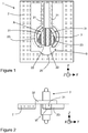
- FIGS. 1 and 2 represent a first embodiment of a watch component 2 according to the invention.
- This component 2 is shown schematically and can be a moving part such as a wheel, a rocker, an anchor, one of the ends of a spiral spring, a display member, or a balance plate.
- the component 2 extends in an XY plane and comprises a first zone B arranged to receive and clamp an axis 3, which extends along an axis perpendicular to the XY plane of the component 2, in particular in the direction Z.
- the axis 3 can be an axis that is intended to be rotatable or a fixed axis.
- the term "axis” is synonymous with “tree", "pad” or any similar structure extending along a geometric axis and to which a watch component 2 may be attached.
- zone B the axis 3 bears against a substantially rigid positioning surface 20, against which it is constrained by a pair of displaceable fingers 23 whose ends constitute holding surfaces 22.
- These fingers 23 are are at the end of two elastic arms 21 which are integral with the component 2, which is thus monobloc. In doing so, when the arms 21 are bent, they apply a restoring force used to bring the fingers 23 towards their rest position (dotted line).
- the positioning surface 20 extends perpendicularly to the XY plane of the component 2.
- the fingers 23 are shaped such that the axis is thus clamped against the positioning surface 20 by the holding surfaces 22, the positioning surface 20 being of curved shape and shaped to conform closely to the shape of the axis 3.
- the positioning surface 20 may be straight or may alternatively comprise one or more discrete contact points.
- the stresses exerted by the elastic arms 21 on the axis 3, as well as the stresses between the axis 3 and the positioning surface 20, are exerted in the XY plane of the component 2.
- the holding surfaces 22 and the positioning surface 23 form at least three contact zones distributed around the periphery of the axis 3 in order to position it and hold it in place.
- the component-axis component constitutes a clock component 1 when the component 2 and the axis 3 are assembled to one another, that is to say in the service position (dashed line).
- the axis 3 comprises two flats 31, each in contact with the holding surface 22 of a corresponding finger 23 in the service position (dashed line).
- the elastic arms are constrained and the fingers bear against the flats 31, which has more resistance against a relative rotation between the axis 3 and the component 2 with a circular section axis.
- only one flat may be in contact with a narrow or discrete positioning surface.
- the axis 3 may be circular, but the resistance to relative rotation between the axis 3 and the component 2 is of course diminished accordingly.
- the manufacturing technologies available for materials such as those covered by the invention make it possible to produce microstructures (microdentures, microcannels, etc.) on the respective surfaces of a "roughly" cylindrical shaft and surfaces in contact with each other. with this one.
- the flats 31 preferably do not extend all along the axis 3, but may occupy a length lying between 100% and 120%, preferably between 101 and 115% of the thickness of the component 2.
- L axis 3 comprises a conventional shoulder 32 against which the component 2 takes place, but the small shoulders formed by the edges of the flats 31 may possibly fulfill the same purpose of the axial positioning of the component 2 on the axis 3.
- the component 2 comprises a second zone A allowing the insertion of the axis 3 in the direction Z, perpendicular to the plane XY of the component 2.
- This second zone A is adjacent to , and in communication with, the first zone B.
- This second zone A is defined by curved portions 23 of the arms 21, which are shaped such that the axis 3 can enter the zone A in a direction perpendicular to the XY plane of the component, without or with little deformation of the arms 21, and ideally without deformation of the curved portions 23 (dashed line) .
- the zone A may be shaped to allow slight deformation of the arms 21 during the insertion of the axis 3, this insertion being in an axial direction perpendicular to the XY plane of the component 2.
- the axis 3 When the desired axial and angular relations of the axis with respect to the component 2 have been obtained in the insertion position of the axis 3 (strong line), the latter is displaced in translation parallel to the XY plane of the component 2 in the direction of the positioning surface 20 to enter the axis in the first zone B.
- the elastic arms 21 deviate to allow the passage of the axis 3 and cleave the latter against the positioning surface 20.
- the axis 3 and component 2 are thus secured in rotation and in translation and thus form a watch assembly 1.
- the Figures 3 and 4 illustrate a second embodiment in which the component 2 is a balance plate and the axis 3 is a balance shaft.
- the plate 2 comprises a pin 201 intended to cooperate in a known manner with a fork of an anchor (not shown).
- Two elastic arms 21 extend symmetrically from the peg 201 and comprise ends 23 shaped to define the zones of The resilient arms 21 are again integral with the component 2.
- the peg 201 constitutes a substantially rigid portion (i.e., having a rigidity such that the elastic deformations in the service does not substantially disturb the function of the component 2), which serves as a support or base for the elastic arms 23.
- the first receiving zone B is defined by one or more positioning surfaces 20 carried by substantially rigid elements 20a, extending towards each other from intermediate portions of the ends of the elastic arms 21, as well as by two fingers 22 which are movable against a restoring force provided by the elastic arms 21 and which again constitute holding surfaces. These fingers 22 are pointed and extend laterally towards each other, the region behind each of the fingers 22 being perforated.
- the second reception zone A is defined by curved surfaces extending from the displaceable fingers 22 and ending in tongues 24. The latter constituting the end portions of the ends 26 of the elastic arms 22 and partially surround the axis 3 when this last is in its insertion position ( figure 3 ).
- the axis 3 can be inserted in the second reception zone A in a direction perpendicular to the XY plane, without constraining the elastic arms 21.
- the tongues 24 can be shaped so that the axis 3 can not leaving the second zone A in a direction opposite to that of said first zone B.
- the outer surface of the shaft 3 lifts the movable fingers 22, thus bending the elastic arms 21
- the displaceable fingers 22 exert a force on the latter tending to constrain its flat 31 against the positioning surfaces 20.
- the component 2 and the axis 3 are thus made integral in rotation with one another to form a micromechanical component 1, in particular a watch component.
- the Figures 5 and 6 illustrate another embodiment of a watch component 2 according to the invention.
- the component 2 is an escapement anchor instead of a balance plate, and the principle of the embodiment of the Figures 1 and 2 has been used.
- the axis 3 has been inserted in the second receiving zone A, between the elastic arms 21, which are curved to fit the shape of the axis 3 and are integral with the component 2.
- the latter is illustrated as a triangle with rounded corners, and therefore comprises three flats 31.
- the axis In the service position (solid lines on the figure 6 ), the axis has been pushed towards the positioning surface 20, against which one of the flats 31 is tightened.
- the axis 3 may be the swing axis and the watch component 2 may be a spiral spring, of which the inner end is attached to, or integrally formed with, the substantially rigid portion 201.
- the same principle also applies to the outer end of a spiral spring.
- the axis 3 may be a cylindrical or prismic stud integral with a cock, the outer end of the spiral being attached to, or integral with, the substantially rigid portion 201.
- a reverse arrangement is also possible , in which the substantially rigid portion 201 is a part of the racking and the axis 3 is a stud or a short shaft integral with the outer end of the hairspring.
- the principle of the invention is particularly advantageous when the component 2 is made of brittle material as mentioned in the preamble, it also applies to components 2 of metal or conventional polymer.
Abstract
Composant horloger (2) destiné à être fixé sur un axe (3) s'étendant selon une première direction (Z), ledit composant (2) étant un ressort spiral, ou un organe d'affichage, ou un balancier, ou une roue, ou une ancre, ou un plateau de balancier et comprenant une première zone de réception (B) délimitée par au moins une surface de positionnement (20) ainsi qu'au moins deux surfaces de maintien (22) dont l'au moins une est déplaçable à l'encontre d'une force de rappel afin de serrer ledit axe (3) contre ladite surface de positionnement (20).Watch component (2) intended to be fixed on an axis (3) extending in a first direction (Z), said component (2) being a spiral spring, or a display member, or a pendulum, or a wheel , or an anchor, or a balance plate and comprising a first receiving zone (B) delimited by at least one positioning surface (20) and at least two holding surfaces (22), the at least one of which is movable against a biasing force to clamp said pin (3) against said positioning surface (20).
Selon l'invention, ledit composant (2) comporte en outre une deuxième zone de réception (A) destinée à recevoir ledit axe, ladite deuxième zone de réception (A) étant adjacente à ladite première zone de réception (B) et en communication avec cette dernière, lesdites surfaces de maintien (22) étant agencées de telle sorte à permettre ledit axe (3) d'être déplacé latéralement en translation depuis ladite deuxième zone afin de le faire entrer dans ladite première zone de réception (B).

Description
La présente invention se rapporte au domaine de l'horlogerie. Elle concerne, plus particulièrement, un composant horloger destiné à être fixé sur un axe afin de former un ensemble horloger.The present invention relates to the field of watchmaking. It relates, more particularly, to a watch component intended to be fixed on an axis in order to form a watch assembly.
Dans le domaine de l'horlogerie, on souhaite souvent intégrer en rotation un composant avec un axe afin de pouvoir monter le composant en pivotement dans le mouvement. Typiquement, cette intégration est effectuée en chassant l'axe dans un trou que comporte le composant. Ce chassage déforme élastiquement le matériau du composant, et les contraintes ainsi engendrées servent à serrer l'axe. Les deux éléments sont ainsi rendus solidaires l'un de l'autre. Lors du chassage, le matériau du composant subit typiquement une légère déformation plastique en plus.In the field of watchmaking, it is often desired to integrate in rotation a component with an axis in order to be able to mount the component in rotation in the movement. Typically, this integration is performed by driving the axis in a hole that includes the component. This hunting deforms elastically the material of the component, and the stresses thus generated serve to tighten the axis. The two elements are thus made integral with one another. During driving, the material of the component typically undergoes a slight plastic deformation in addition.
Ce procédé de fixation convient parfaitement pour des composants en métal ou en polymère qui sont relativement élastiques et peuvent subir des déformations plastiques sans casser.This method of attachment is ideal for metal or polymer components that are relatively resilient and can undergo plastic deformation without breaking.
Plus récemment, des matériaux cassants sont devenus courant dans l'horlogerie. Ces matériaux présentent peu ou pas, de domaine plastique et sont donc extrêmement fragiles. À ce titre, on peut citer des aciers durs, des céramiques, des verres, des vitrocéramiques, le silicium mono- ou polycristallin, le silicium amorphe, des oxydes nitrures ou carbures de silicium sous tout régime cristallin, l'alumine, le diamant synthétique et similaires.More recently, brittle materials have become commonplace in watchmaking. These materials have little or no plastic field and are therefore extremely fragile. In this respect, mention may be made of hard steels, ceramics, glasses, glass-ceramics, monocrystalline silicon, amorphous silicon, nitride oxides or silicon carbides under any crystalline regime, alumina or synthetic diamond. and the like.
Étant donné que ces matériaux sont cassants, il est très difficile, voire impossible de chasser un composant fait d'un tel matériau sur un axe de manière traditionnelle, tout en gardant des tolérances de fabrication acceptables.Since these materials are brittle, it is very difficult, if not impossible, to drive a component made of such material onto an axis in a conventional manner, while maintaining acceptable manufacturing tolerances.
Pour ces raisons, des fabricants horlogers ont développé plusieurs solutions pour monter des composants faits en de tels matériaux sur des axes. L'une de ces solutions est de prévoir des structures élastiques au niveau de la zone de montage du composant, ces structures élastiques permettant un chassage sans développement de contraintes excessives dans le matériau du composant. Ces structures sont typiquement formées dans le corps du composant et fléchissent lors de l'introduction de l'axe.For these reasons, watch manufacturers have developed several solutions for mounting components made of such materials on axes. One of these solutions is to provide resilient structures at the component mounting area, these elastic structures allowing a hunting without development of excessive stresses in the component material. These structures are typically formed in the body of the component and flex when introducing the axis.
À ce titre, on peut citer le document
Un autre document intéressant est le
Le document
Le but de l'invention est par conséquent de proposer un composant horloger dans lequel les défauts susmentionnés sont au moins partiellement surmontés.The object of the invention is therefore to provide a watch component in which the aforementioned defects are at least partially overcome.
De façon plus précise, l'invention concerne un composant horloger comme défini par la revendication 1 annexée. Ce composant peut être, par exemple, une roue, l'extrémité intérieure ou extérieure d'un spiral ou tout autre pièce horlogère destinée à être fixée sur un axe qui s'étend selon une première direction, axiale.More specifically, the invention relates to a timepiece component as defined by appended
Le composant, qui est un ressort spiral, un balancier, un organe d'affichage, une roue, une ancre ou un plateau de balancier, comprend une première zone de réception délimitée par au moins une surface de positionnement ainsi qu'au moins deux surfaces de maintien, tels que des doigts. Au moins l'une, de préférence chacune, de ces surfaces de maintien est déplaçable à l'encontre d'une force de rappel afin de contraindre ledit axe contre ladite surface de positionnement, notamment dans le plan dudit composant. À cet effet, les surfaces de maintien peuvent par exemple être venues de matière avec des bras élastiques ou peuvent être soumises à des forces élastiques de rappel fournies par des éléments élastiques distincts.The component, which is a spiral spring, a rocker, a display member, a wheel, an anchor or a balance plate, comprises a first receiving zone delimited by at least one positioning surface and at least two surfaces. keeping, such as fingers. At least one, preferably each, of these holding surfaces is movable against a restoring force in order to constrain said axis against said positioning surface, in particular in the plane of said component. For this purpose, the holding surfaces may for example be integral with elastic arms or may be subject to elastic return forces provided by separate elastic members.
Selon l'invention, le composant comporte en outre une deuxième zone de réception destinée à recevoir ledit axe, les deux zones de réception étant adjacentes et en communication l'une par rapport à l'autre, lesdites surfaces de maintien étant agencées de telle sorte à permettre ledit axe d'être déplacé latéralement (c'est-à-dire à un angle non zéro, notamment perpendiculaire à, ladite première direction) en translation depuis ladite deuxième zone afin de lui faire entrer dans ladite première zone.According to the invention, the component further comprises a second receiving zone intended to receive said axis, the two receiving zones being adjacent and in communication with one another, said holding surfaces being arranged in such a way permitting said axis to be moved laterally (i.e., at a non-zero angle, especially perpendicular to, said first direction) in translation from said second area to enter said first area.
Cette construction permet de clipser l'axe dans la première zone de réception au lieu de le chasser là-dedans, le serrage de l'axe s'effectuant par le biais de contraintes qui s'exercent dans le plan dudit composant afin de serrer son pourtour. La deuxième zone de réception permet l'insertion de l'axe selon une direction axiale, avantageusement sans contact, sans risque d'usure des surfaces de maintien ou de la surface de positionnement, et la solidarisation du composant sur l'axe s'effectue donc en déplaçant l'axe latéralement, c'est-à-dire dans le plan du composant afin d'écarter les surfaces de maintien pour permettre le passage de l'axe. Par ailleurs, le montage du composant sur l'axe est facilité par rapport à un chassage connu, notamment au niveau de la détermination de la position axiale du composant sur l'axe.This construction makes it possible to clip the axis in the first reception zone instead of driving it therein, the clamping of the axis being effected by means of stresses which are exerted in the plane of said component in order to tighten its axis. periphery. The second reception zone allows the insertion of the axis in an axial direction, advantageously without contact, without risk of wear of the holding surfaces or the positioning surface, and the component of the fastening on the axis is therefore effected by moving the axis laterally, c ' that is to say in the plane of the component in order to separate the holding surfaces to allow the passage of the axis. Moreover, the mounting of the component on the axis is facilitated with respect to a known driving, in particular at the level of the determination of the axial position of the component on the axis.
Avantageusement, ladite deuxième zone est conformée de telle sorte que ledit axe peut prendre place là-dedans sans déplacement desdites surfaces de maintien. Tout frottement (et donc tout usure) entre le composant et l'axe lors de l'insertion de ce dernier est ainsi éliminé. Comme mentionné ci-dessus, cette insertion s'effectue, bien entendu, selon une direction parallèle à l'axe géométrique longitudinal dudit axe, le long duquel ledit axe s'étend.Advantageously, said second zone is shaped such that said axis can take place there without displacement of said holding surfaces. Any friction (and therefore any wear) between the component and the axis during the insertion of the latter is thus eliminated. As mentioned above, this insertion is effected, of course, in a direction parallel to the longitudinal geometric axis of said axis, along which said axis extends.
Avantageusement, ledit composant comprend une partie sensiblement rigide ainsi qu'au moins un, et avantageusement deux, bras élastiques s'étendant depuis ladite partie sensiblement rigide, le ou lesdits bras élastiques comprenant des extrémités conformées pour définir au moins l'une de ladite première zone et ladite deuxième zone, de préférence chacune desdites zones. Dans un tel cas, le composant peut être choisi parmi un ressort spiral, un balancier, une roue, une ancre, et un plateau de balancier. En particulier, le composant peut notamment être un plateau de balancier et la partie substantiellement rigide peut être une cheville destinée à interagir avec une fourchette d'une ancre.Advantageously, said component comprises a substantially rigid portion and at least one, and advantageously two, elastic arms extending from said substantially rigid portion, said elastic arm or arms comprising ends shaped to define at least one of said first zone and said second zone, preferably each of said zones. In such a case, the component may be selected from a spiral spring, a balance wheel, a wheel, an anchor, and a balance plate. In particular, the component may in particular be a balance plate and the substantially rigid portion may be an anchor intended to interact with a fork of an anchor.
Un composant monobloc qui est simple à positionner correctement sur l'axe est ainsi proposé.A monobloc component that is easy to position correctly on the axis is thus proposed.
Avantageusement, lesdites surfaces de maintien font partie de doigts s'étendent chacun l'un vers l'autre depuis des extrémités respectives de chacun desdits bras élastiques. Une solution compacte est ainsi proposée.Advantageously, said holding surfaces are part of fingers each extending towards each other from respective ends of each of said elastic arms. A compact solution is thus proposed.
Avantageusement, ladite au moins une surface de positionnement est répartie entre deux surfaces que comportent des éléments qui s'étendent l'un vers l'autre depuis une extrémité respective de chacun desdits bras élastiques. L'élasticité des bras peut ainsi être déterminée indépendamment de la forme des surfaces de positionnement.Advantageously, said at least one positioning surface is distributed between two surfaces that comprise elements that extend towards one another from a respective end of each of said arms. elastic. The elasticity of the arms can thus be determined independently of the shape of the positioning surfaces.
Avantageusement, ladite deuxième zone est définie par lesdites surfaces de maintien ainsi que deux langues constituant chacune une partie terminale d'une respective desdites extrémités. Les langues permettent de définir une deuxième zone discrète et peuvent être conformées de telle sorte que l'axe ne puisse pas sortir intempestivement de la deuxième zone selon une direction indésirée.Advantageously, said second zone is defined by said holding surfaces and two languages each constituting an end portion of a respective one of said ends. The languages make it possible to define a second discrete zone and can be shaped in such a way that the axis can not leave the second zone unexpectedly in an undesired direction.
Le composant peut faire partie d'un ensemble horloger dans lequel le composant est monté sur ledit axe. Cet ensemble peut être par exemple un mobile, un spiral monté sur un axe de balancier, un spiral monté sur un porte-piton ou tout autre ensemble approprié.The component may be part of a watch assembly in which the component is mounted on said axis. This assembly can be for example a mobile, a spiral mounted on a balance shaft, a spiral mounted on a bolt carrier or any other appropriate assembly.
Avantageusement, ledit axe comporte au moins un méplat, ou tout contour équivalent en fonction, en contact avec l'une desdites surfaces de maintien ou avec ladite surface de positionnement. Ce méplat (ou méplats) augmente la résistance à une rotation du composant par rapport à l'axe en position de service, ce qui réduit le risque d'une désindexation de ces deux éléments.Advantageously, said axis comprises at least one flat, or any contour equivalent in function, in contact with one of said holding surfaces or with said positioning surface. This flat (or flats) increases the resistance to a rotation of the component relative to the axis in the service position, which reduces the risk of deindexation of these two elements.
Avantageusement, ledit au moins un méplat présente une hauteur parallèle audite première direction qui se situe entre 100% et 120%, de préférence entre 101% et 115%, de l'épaisseur dudit composant considéré selon la même direction. Le méplat (ou les méplats) peut ainsi servir pour définir la position axiale du composant sur l'axe sans nécessiter d'autres moyens de butée. Cependant, la présence d'un épaulement supplémentaire n'est pas exclue.Advantageously, said at least one flat has a parallel height audite first direction which is between 100% and 120%, preferably between 101% and 115%, of the thickness of said component considered in the same direction. The flat (or flats) can thus be used to define the axial position of the component on the axis without requiring other abutment means. However, the presence of an additional shoulder is not excluded.
L'invention concerne également un procédé de fixation d'un composant horloger sur un axe afin de former un ensemble horloger. Ce procédé comprend les étapes de :
- fournir un composant horloger comme défini ci-dessus ;
- fournir un axe ;
- insérer ledit axe dans ladite deuxième zone selon une direction parallèle à ladite première direction ;
- déplacer ledit axe latéralement en translation afin de le faire entrer dans ladite première zone.
- provide a watch component as defined above;
- provide an axis;
- inserting said axis in said second zone in a direction parallel to said first direction;
- moving said axis laterally in translation to enter said first zone.
Par conséquent, aucun chassage du composant sur l'axe n'est nécessaire, puisque la fixation de ces deux éléments s'effectue par l'intermédiaire d'un clipsage comme mentionné ci-dessus. L'usure du composant lors de sa fixation sur l'axe est ainsi réduite.Therefore, no driving of the component on the axis is necessary, since the attachment of these two elements is effected by means of a clipping as mentioned above. The wear of the component during its attachment to the axis is thus reduced.
Avantageusement, ledit axe comporte au moins un méplat destiné à être en contact avec au moins l'une desdites surfaces de maintien et/ou ladite surface de positionnement, ledit procédé comprenant en outre une étape d'alignement dudit méplat avant de faire entrer ledit axe dans ladite deuxième zone. Tout alignement ultérieur du composant par rapport à l'axe est ainsi rendu superflu.Advantageously, said axis comprises at least one flat part intended to be in contact with at least one of said holding surfaces and / or said positioning surface, said method further comprising a step of aligning said flat surface before entering said axis. in said second zone. Any subsequent alignment of the component with respect to the axis is thus rendered superfluous.
D'autres détails de l'invention apparaîtront plus clairement à la lecture de la description qui suit, faite en référence aux dessins annexés dans lesquels :
-
Fig. 1a est une représentation schématique en plan d'un composant horloger selon l'invention en position de service ; -
Fig. 1b est une représentation schématique en plan du composant horloger de lafigure 1a en position d'insertion de l'axe ; -
Fig. 2 est une représentation schématique latérale du composant horloger de lafigure 1a en position de service (trait fort) et en position d'insertion (trait discontinu); -
Fig. 3 est une représentation schématique en plan d'une variante d'un composant horloger selon l'invention en position d'insertion de l'axe ; -
Fig. 4 est une représentation schématique en plan du composant horloger de lafigure 3 en position de service ; et -
Fig. 5 est une représentation schématique en plan d'encore une variante d'un composant horloger en position d'insertion. -
Fig. 6 est une représentation schématique en plan de la variante de lafig. 5 en position de service
-
Fig. 1a is a schematic representation in plan of a watch component according to the invention in the service position; -
Fig. 1b is a schematic representation in plan of the watchmaking component of thefigure 1a in insertion position of the axis; -
Fig. 2 is a schematic side view of the watchmaking component of thefigure 1a in the service position (strong line) and in the insertion position (dashed line); -
Fig. 3 is a schematic representation in plan of a variant of a watch component according to the invention in insertion position of the axis; -
Fig. 4 is a schematic representation in plan of the watchmaking component of thefigure 3 in the service position; and -
Fig. 5 is a schematic representation in plan of yet another variant of a watchmaker component in the insertion position. -
Fig. 6 is a schematic representation in plan of the variant of theFig. 5 in service position
Les
Ce composant 2 est représenté schématiquement et peut être une pièce mobile telle qu'une roue, un balancier, une ancre, l'une des extrémités d'un ressort spiral, un organe d'affichage, ou un plateau de balancier.This
Le composant 2 s'étend dans un plan XY et comporte une première zone B agencée pour recevoir et serrer un axe 3, qui s'étend selon un axe perpendiculaire au plan XY du composant 2, notamment selon la direction Z. L'axe 3 peut être un axe qui est destiné à être mobile en rotation ou un axe fixe. Dans le contexte de l'invention, le terme « axe » est synonyme avec « arbre », « plot » ou toute structure similaire s'étendant le long d'un axe géométrique et auquel un composant horloger 2 peut être fixé.The
Dans la zone B (trait pointillé), l'axe 3 prend appui contre une surface de positionnement 20 substantiellement rigide, contre laquelle il est contraint par une paire de doigts déplaçables 23 dont les extrémités constituent des surfaces de maintien 22. Ces doigts 23 se trouvent à l'extrémité de deux bras élastiques 21 qui sont venus de matière avec le composant 2, qui est ainsi monobloc. Ce faisant, lorsque les bras 21 sont fléchis, ils appliquent une force de rappel servant pour ramener les doigts 23 en direction de leur position de repos (trait pointillé). La surface de positionnement 20 s'étend perpendiculairement au plan XY du composant 2.In zone B (dotted line), the
Les doigts 23 sont conformés de telle sorte que l'axe est ainsi serré contre la surface de positionnement 20 par les surfaces de maintien 22, la surface de positionnement 20 étant de forme courbée et conformée pour épouser étroitement la forme de l'axe 3. Cependant, la surface de positionnement 20 peut être droite ou peut alternativement comprendre un ou plusieurs points de contact discrets. À cet effet, les contraintes exercées par les bras élastiques 21 sur l'axe 3, ainsi que les contraintes entre l'axe 3 et la surface de positionnement 20, s'exercent dans le plan XY du composant 2. Les surfaces de maintien 22 et la surface de positionnement 23 forment au moins trois zones de contact distribuées autour du pourtour de l'axe 3 afin de le positionner et de le maintenir en place. Ces aspects s'appliquent également aux autres modes de réalisation de l'invention décrits ci-dessous, et ne doivent donc pas être répétés à chaque reprise.The
L'ensemble composant-axe constitue un composant horloger 1 lorsque le composant 2 et l'axe 3 sont assemblés l'un à l'autre, c'est-à-dire dans la position de service (trait pointillé).The component-axis component constitutes a
Dans la variante illustrée, l'axe 3 comporte deux méplats 31, chacun en contact avec la surface de maintien 22 d'un doigt 23 correspondant en position de service (trait pointillé). Ce faisant, lorsque l'axe 3 se trouve dans la première zone B (
Comme visible sur la
Pour permettre le montage du composant 2 sur l'axe 3, le composant 2 comporte une deuxième zone A permettant l'insertion de l'axe 3 selon la direction Z, perpendiculaire du plan XY du composant 2. Cette deuxième zone A est adjacente à, et en communication avec, la première zone B. Cette deuxième zone A est définie par des parties courbées 23 des bras 21, qui sont conformées de telle sorte que l'axe 3 peut entrer dans la zone A selon une direction perpendiculaire au plan XY du composant, et ce sans ou avec peu de déformation des bras 21, et idéalement sans déformation des parties courbées 23 (trait pointillé). Alternativement, la zone A peut être conformée pour permettre une légère déformation des bras 21 lors de l'insertion de l'axe 3, cette insertion étant selon une direction axiale, perpendiculaire au plan XY du composant 2.To allow the assembly of the
Lorsque les relations axiales et angulaires désirées de l'axe par rapport au composant 2 ont été obtenues en position d'insertion de l'axe 3 (trait fort), ce dernier est déplacé en translation parallèle au plan XY du composant 2 en direction de la surface de positionnement 20 afin de faire entrer l'axe dans la première zone B. Les bras élastiques 21 s'écartent pour permettre le passage de l'axe 3 et effectuent un clipsage de ce dernier contre la surface de positionnement 20. L'axe 3 et le composant 2 sont ainsi rendus solidaires en rotation et en translation et forment ainsi un ensemble horloger 1.When the desired axial and angular relations of the axis with respect to the
Afin de désolidariser l'axe 3 et le composant 2, il suffit de surmonter la force de rétention fournie par les doigts 22, 23 et les bras élastiques 21, en poussant l'axe en translation parallèle au plan XY en direction de la deuxième zone A. L'axe 3 peut subséquemment être sorti du composant selon la direction Z.In order to separate the
Grâce à cet agencement, aucun chassage du composant sur l'axe n'est nécessaire, ce qui réduit l'usure des parties du composant 2 en contact avec l'axe 3. En effet, un chassage conventionnel engendre des frottements entre les structures élastiques et l'axe qui peuvent être bien supérieurs à ceux exercés lors du clipsage de l'axe 3 dans la première zone B dans l'agencement de l'invention.Thanks to this arrangement, it is not necessary to drive the component on the axis, which reduces the wear of the parts of the
Les
La première zone de réception B est définie par une ou plusieurs surfaces de positionnement 20 portées par des éléments substantiellement rigides 20a, s'étendant l'un vers l'autre depuis des parties intermédiaires des extrémités des bras élastiques 21, ainsi que par deux doigts 22 qui sont déplaçables à l'encontre d'une force de rappel fournie par les bras élastiques 21 et qui constituent à nouveau des surfaces de maintien. Ces doigts 22 sont pointus et s'étendent latéralement l'un vers l'autre, la région derrière chacun des doigts 22 étant ajourée. La deuxième zone de réception A est définie par des surfaces courbées s'étendant depuis les doigts déplaçables 22 et se terminant par des langues 24. Ces dernières constituant les parties terminales des extrémités 26 des bras élastiques 22 et entourent partiellement l'axe 3 lorsque ce dernier se trouve dans sa position d'insertion (
En alignant le méplat 31 que comporte l'axe 3 avec les surfaces de positionnement 20 et en déplaçant l'axe en direction de la cheville 21, la surface extérieure de l'axe 3 soulève les doigts déplaçables 22, ainsi fléchissant les bras élastiques 21. Une fois que les doigts déplaçables 22 ont été dépassés par la partie la plus large de l'axe 3, les doigts déplaçables 22 exercent une force sur ce dernier tendant à contraindre son méplat 31 contre les surfaces de positionnement 20. Le composant 2 et l'axe 3 sont ainsi rendus solidaires en rotation l'un de l'autre afin de former un composant de micromécanique 1, notamment un composant horloger.By aligning the
Les
Sur la
Il faut noter que, même si les variantes illustrées sur les
Même si le principe de l'invention est particulièrement avantageux lorsque le composant 2 est fabriqué en matériau cassant comme mentionné en préambule, il s'applique également à des composants 2 en métal ou en polymère conventionnel.Although the principle of the invention is particularly advantageous when the
Bien que l'invention ait été particulièrement montrée et décrite en se référant à des modes de réalisation particuliers, d'autres variantes sont possibles sans sortir du cadre de l'invention comme définie dans les revendications. Par exemple, il est possible que l'une seule des surfaces de maintien 22 soit déplaçable élastiquement, l'autre étant substantiellement rigide. L'homme du métier est en état de modifier la géométrie des zones A et B afin d'appliquer cette possibilité.Although the invention has been particularly shown and described with reference to particular embodiments, other variations are possible without departing from the scope of the invention as defined in the claims. For example, it is possible that only one of the holding surfaces 22 is elastically displaceable, the other being substantially rigid. Those skilled in the art are able to modify the geometry of the zones A and B in order to apply this possibility.
Claims (13)
Applications Claiming Priority (1)
| Application Number | Priority Date | Filing Date | Title |
|---|---|---|---|
| CH00940/17A CH713999B1 (en) | 2017-07-18 | 2017-07-18 | Watch component intended to be fixed on an axis. |
Publications (1)
| Publication Number | Publication Date |
|---|---|
| EP3432080A1 true EP3432080A1 (en) | 2019-01-23 |
Family
ID=59930144
Family Applications (1)
| Application Number | Title | Priority Date | Filing Date |
|---|---|---|---|
| EP18183686.7A Withdrawn EP3432080A1 (en) | 2017-07-18 | 2018-07-16 | Clockwork component |
Country Status (2)
| Country | Link |
|---|---|
| EP (1) | EP3432080A1 (en) |
| CH (1) | CH713999B1 (en) |
Cited By (1)
| Publication number | Priority date | Publication date | Assignee | Title |
|---|---|---|---|---|
| JP2022529407A (en) * | 2019-04-08 | 2022-06-22 | ニヴァロックス-ファー ソシエテ アノニム | Elastic retention member for fixing timekeeping components to various support elements |
Citations (5)
| Publication number | Priority date | Publication date | Assignee | Title |
|---|---|---|---|---|
| CH306105A (en) * | 1953-02-17 | 1955-03-31 | Omega Brandt & Freres Sa Louis | Device for fixing a wheel of a clockwork movement on the end of a shaft. |
| FR2394839A1 (en) * | 1977-06-14 | 1979-01-12 | Seiko Koki Kk | FRICTION MECHANISM FOR A WATCH |
| WO2011116486A1 (en) * | 2010-03-25 | 2011-09-29 | Rolex S.A. | Split collet with a non-circular opening |
| WO2013045706A2 (en) * | 2011-09-29 | 2013-04-04 | Rolex S.A. | Integral assembly of a hairspring and a collet |
| JP2014190816A (en) * | 2013-03-27 | 2014-10-06 | Citizen Holdings Co Ltd | Spring device for timepiece |
-
2017
- 2017-07-18 CH CH00940/17A patent/CH713999B1/en unknown
-
2018
- 2018-07-16 EP EP18183686.7A patent/EP3432080A1/en not_active Withdrawn
Patent Citations (5)
| Publication number | Priority date | Publication date | Assignee | Title |
|---|---|---|---|---|
| CH306105A (en) * | 1953-02-17 | 1955-03-31 | Omega Brandt & Freres Sa Louis | Device for fixing a wheel of a clockwork movement on the end of a shaft. |
| FR2394839A1 (en) * | 1977-06-14 | 1979-01-12 | Seiko Koki Kk | FRICTION MECHANISM FOR A WATCH |
| WO2011116486A1 (en) * | 2010-03-25 | 2011-09-29 | Rolex S.A. | Split collet with a non-circular opening |
| WO2013045706A2 (en) * | 2011-09-29 | 2013-04-04 | Rolex S.A. | Integral assembly of a hairspring and a collet |
| JP2014190816A (en) * | 2013-03-27 | 2014-10-06 | Citizen Holdings Co Ltd | Spring device for timepiece |
Cited By (1)
| Publication number | Priority date | Publication date | Assignee | Title |
|---|---|---|---|---|
| JP2022529407A (en) * | 2019-04-08 | 2022-06-22 | ニヴァロックス-ファー ソシエテ アノニム | Elastic retention member for fixing timekeeping components to various support elements |
Also Published As
| Publication number | Publication date |
|---|---|
| CH713999B1 (en) | 2021-05-31 |
| CH713999A1 (en) | 2019-01-31 |
Similar Documents
| Publication | Publication Date | Title |
|---|---|---|
| EP2799937B1 (en) | Shock-proof bearing for an horological balance | |
| CH699680A2 (en) | Mobile e.g. escape wheel, fixing device for clock movement, has intermediate piece partially distributing constraints exerted by support element formed of escapement sprocket, pallet staff and pin when element is driven into central hole | |
| EP3623876A1 (en) | Split collar with non-circular opening | |
| CH705276B1 (en) | Body workout and transmission to a lever escapement, and exhaust tray being equipped and timepiece comprising them. | |
| EP3220211B1 (en) | Shock absorbing system with angular locking | |
| EP2743781B1 (en) | Device for assembly by locking a joint | |
| EP1826635B1 (en) | Resilient fastening device for horology | |
| EP3179315B1 (en) | Stud support with secure mounting | |
| EP3432081B1 (en) | Timepiece assembly | |
| EP3432080A1 (en) | Clockwork component | |
| EP2075652B1 (en) | Driving and transmission element for an escapement, plate and escapement equipped with it, and timepiece comprising them | |
| EP3179314B1 (en) | Stud support with simplified assembly | |
| EP2977833B1 (en) | Accurate positioning of a timepiece bridge | |
| EP3032353B1 (en) | Detachable stud support | |
| EP2816423A1 (en) | Securely mounted anti-shock system | |
| EP3432082B1 (en) | Regulating mechanism | |
| CH698794B1 (en) | Timepiece component e.g. hairspring, maintaining elastic body e.g. collet, for use during assembling and operation of watch, has arms presenting variable width to make uniform distribution of stresses exerted on arm by support element | |
| CH709282A2 (en) | suspended anchor watch escapement. | |
| CH700811B1 (en) | Silicon mechanical piece e.g. gear train, for mechanical timepiece, has clamp comprising jaws that extend in direction of upper beam and include lower flanks, where jaws are placed on both sides of preferential flexural zone | |
| CH709903A2 (en) | All removable clock. | |
| EP3428738B1 (en) | Drive and positioning system and jumper for implementing said system | |
| CH712197A2 (en) | Friction system for a watch movement and its assembly process. | |
| CH707884A2 (en) | watch Spiral fragile material. | |
| CH711900A2 (en) | Piton mount with secure mounting. | |
| CH710491A2 (en) | Holding assembly or support of a timepiece balance spring. |
Legal Events
| Date | Code | Title | Description |
|---|---|---|---|
| PUAI | Public reference made under article 153(3) epc to a published international application that has entered the european phase |
Free format text: ORIGINAL CODE: 0009012 |
|
| STAA | Information on the status of an ep patent application or granted ep patent |
Free format text: STATUS: THE APPLICATION HAS BEEN PUBLISHED |
|
| AK | Designated contracting states |
Kind code of ref document: A1 Designated state(s): AL AT BE BG CH CY CZ DE DK EE ES FI FR GB GR HR HU IE IS IT LI LT LU LV MC MK MT NL NO PL PT RO RS SE SI SK SM TR |
|
| AX | Request for extension of the european patent |
Extension state: BA ME |
|
| STAA | Information on the status of an ep patent application or granted ep patent |
Free format text: STATUS: REQUEST FOR EXAMINATION WAS MADE |
|
| 17P | Request for examination filed |
Effective date: 20190708 |
|
| RBV | Designated contracting states (corrected) |
Designated state(s): AL AT BE BG CH CY CZ DE DK EE ES FI FR GB GR HR HU IE IS IT LI LT LU LV MC MK MT NL NO PL PT RO RS SE SI SK SM TR |
|
| STAA | Information on the status of an ep patent application or granted ep patent |
Free format text: STATUS: EXAMINATION IS IN PROGRESS |
|
| 17Q | First examination report despatched |
Effective date: 20200331 |
|
| STAA | Information on the status of an ep patent application or granted ep patent |
Free format text: STATUS: THE APPLICATION IS DEEMED TO BE WITHDRAWN |
|
| 18D | Application deemed to be withdrawn |
Effective date: 20200811 |