EP3431962A1 - Observing device and observing method - Google Patents
Observing device and observing method Download PDFInfo
- Publication number
- EP3431962A1 EP3431962A1 EP17766390.3A EP17766390A EP3431962A1 EP 3431962 A1 EP3431962 A1 EP 3431962A1 EP 17766390 A EP17766390 A EP 17766390A EP 3431962 A1 EP3431962 A1 EP 3431962A1
- Authority
- EP
- European Patent Office
- Prior art keywords
- light
- split light
- image
- observation
- observation object
- Prior art date
- Legal status (The legal status is an assumption and is not a legal conclusion. Google has not performed a legal analysis and makes no representation as to the accuracy of the status listed.)
- Withdrawn
Links
Images




Classifications
-
- G—PHYSICS
- G01—MEASURING; TESTING
- G01N—INVESTIGATING OR ANALYSING MATERIALS BY DETERMINING THEIR CHEMICAL OR PHYSICAL PROPERTIES
- G01N15/00—Investigating characteristics of particles; Investigating permeability, pore-volume or surface-area of porous materials
- G01N15/10—Investigating individual particles
- G01N15/14—Optical investigation techniques, e.g. flow cytometry
- G01N15/1434—Optical arrangements
-
- G—PHYSICS
- G01—MEASURING; TESTING
- G01N—INVESTIGATING OR ANALYSING MATERIALS BY DETERMINING THEIR CHEMICAL OR PHYSICAL PROPERTIES
- G01N15/00—Investigating characteristics of particles; Investigating permeability, pore-volume or surface-area of porous materials
- G01N15/10—Investigating individual particles
- G01N15/14—Optical investigation techniques, e.g. flow cytometry
- G01N15/1434—Optical arrangements
- G01N15/1436—Optical arrangements the optical arrangement forming an integrated apparatus with the sample container, e.g. a flow cell
-
- G—PHYSICS
- G01—MEASURING; TESTING
- G01N—INVESTIGATING OR ANALYSING MATERIALS BY DETERMINING THEIR CHEMICAL OR PHYSICAL PROPERTIES
- G01N15/00—Investigating characteristics of particles; Investigating permeability, pore-volume or surface-area of porous materials
- G01N15/10—Investigating individual particles
- G01N15/14—Optical investigation techniques, e.g. flow cytometry
- G01N15/1468—Optical investigation techniques, e.g. flow cytometry with spatial resolution of the texture or inner structure of the particle
- G01N15/147—Optical investigation techniques, e.g. flow cytometry with spatial resolution of the texture or inner structure of the particle the analysis being performed on a sample stream
-
- G—PHYSICS
- G01—MEASURING; TESTING
- G01N—INVESTIGATING OR ANALYSING MATERIALS BY DETERMINING THEIR CHEMICAL OR PHYSICAL PROPERTIES
- G01N21/00—Investigating or analysing materials by the use of optical means, i.e. using sub-millimetre waves, infrared, visible or ultraviolet light
- G01N21/17—Systems in which incident light is modified in accordance with the properties of the material investigated
- G01N21/41—Refractivity; Phase-affecting properties, e.g. optical path length
- G01N21/45—Refractivity; Phase-affecting properties, e.g. optical path length using interferometric methods; using Schlieren methods
-
- G—PHYSICS
- G01—MEASURING; TESTING
- G01N—INVESTIGATING OR ANALYSING MATERIALS BY DETERMINING THEIR CHEMICAL OR PHYSICAL PROPERTIES
- G01N15/00—Investigating characteristics of particles; Investigating permeability, pore-volume or surface-area of porous materials
- G01N15/10—Investigating individual particles
- G01N15/14—Optical investigation techniques, e.g. flow cytometry
- G01N15/1434—Optical arrangements
- G01N2015/1454—Optical arrangements using phase shift or interference, e.g. for improving contrast
-
- G—PHYSICS
- G01—MEASURING; TESTING
- G01N—INVESTIGATING OR ANALYSING MATERIALS BY DETERMINING THEIR CHEMICAL OR PHYSICAL PROPERTIES
- G01N15/00—Investigating characteristics of particles; Investigating permeability, pore-volume or surface-area of porous materials
- G01N15/10—Investigating individual particles
- G01N15/14—Optical investigation techniques, e.g. flow cytometry
- G01N2015/1497—Particle shape
Definitions
- An aspect of the present invention relates to an observation apparatus and an observation method which observes an observation object moving in a flow path with a fluid.
- the flow path is a flow cell
- the fluid is blood
- the observation object is a red blood cell, a white blood cell, a circulating tumor cell (hereinafter, referred to as "CTC") in the blood, and the like.
- the CTC is a cell which is separated from a primary tumor tissue or a metastatic tumor tissue and enters the blood, and is found infinitesimally in peripheral blood of a solid cancer patient, and is involved in metastasis.
- An object can generally be identified on the basis of size, shape, or color.
- the white blood cell and the CTC are not so different in size, and both are colorless and transparent, and therefore, both cells are hard to be identified from an image obtained by a bright field microscope.
- a phase contrast microscope and a differential interference microscope are used to visualize a colorless and transparent cell, but there is a defect in quantitativity with respect to an optical thickness.
- the focal depth of these microscopes is equal to or less than a thickness of the cell depending on a using objective lens, and therefore, only two-dimensional information can be obtained even though the cell is structured three-dimensionally, and thus the object is not possible to be identified.
- the phase image is generated on the basis of the interference image of the observation object which flows in the flow path with the fluid, and a shape (an external form, a shape of a nucleus, or the like) of the observation object is analyzed on the basis of the phase image, and therefore, the CTC in the blood can be identified.
- the conventional observation apparatus splits light output from a light source into first split light and second split light, reflects or transmits the first split light by the observation object in the flow path, causes interference between the first split light and the second split light to repeatedly acquire two-dimensional interference images, and generates the phase image of the observation object on the basis of these two-dimensional interference images.
- the conventional observation apparatus uses an imaging unit having a plurality of pixels two-dimensionally arranged on an imaging plane.
- the observation objects flow in the flow path continuously. Therefore, in the conventional observation apparatus, particularly in a case where a moving speed of the observation object is not constant, an image of the observation object may be partially damaged between continuous two two-dimensional interference images in a plurality of two-dimensional interference images acquired by the imaging unit, and in that case, the partially damaged portion of the image is not possible to be recovered even when being subjected to image processing. In such a case, the observation object is hard to be identified.
- the conventional observation apparatus when generating the phase image on the basis of the interference image, there is a need to acquire a plurality of two-dimensional interference images in a period when the observation object seems to be stopped.
- the conventional observation apparatus also has a problem derived from this.
- An aspect of the present invention has been made in order to solve the above problem, and an object thereof is to provide an observation apparatus and an observation method which can easily generate an excellent two-dimensional image of the observation object moving in a flow path with a fluid.
- An observation apparatus for observing an observation object moving in a flow path with a fluid, and includes (1) a light source for outputting light; (2) an interference optical system for splitting the light into first split light and second split light, reflecting or transmitting the first split light by the observation object, and combining the first split light and the second split light to output combined light; (3) a modulation unit for temporally changing a phase difference between the first split light and the second split light at the combining; (4) an imaging unit including a plurality of pixels arranged in a direction intersecting with a moving direction of an image of the observation object on a light receiving plane on which the image of the observation object is formed, and for receiving the combined light to repeatedly output a detection signal indicating a one-dimensional interference image; and (5) an analysis unit for generating a two-dimensional image of the observation object on the basis of the detection signal.
- An observation method is an observation method of observing an observation object moving in a flow path with a fluid, and includes (1) a step of outputting light; (2) a step of splitting the light into first split light and second split light; (3) a step of reflecting or transmitting the first split light by the observation object; (4) a modulation step of temporally changing a phase difference between the first split light and the second split light; (5) a detection step of receiving combined light of the first split light and the second split light by an imaging unit to repeatedly output a detection signal indicating a one-dimensional interference image in a direction intersecting with a moving direction of an image of the observation object on a light receiving plane of the imaging unit on which the image of the observation object is formed; and (6) an analysis step of generating a two-dimensional image of the observation object on the basis of the detection signal.
- FIG. 1 is a diagram illustrating a configuration of an observation apparatus 1 of a first embodiment.
- the observation apparatus 1 generates a phase image on the basis of an interference image of an observation object 30 which flows in a flow path 10 with a fluid 20.
- the flow path 10 is a flow cell
- the fluid 20 is blood
- the observation object 30 is a red blood cell, a white blood cell, a CTC, and the like.
- the observation apparatus 1 includes a light source 101, an optical fiber 102, a splitting unit 111, a combining unit 112, an optical fiber 121, a collimator 122, a cylindrical lens 123, an objective lens 125, an optical fiber 131, a collimator 132, a cylindrical lens 133, a mirror 134, an objective lens 135, a modulation unit 140, a lens 151, an imaging unit 152, an analysis unit 161, and a display unit 162.
- the light source 101 outputs light.
- the light source 101 may output temporally and spatially coherent light, only the temporally coherent light, or only the spatially coherent light. Further, the light source 101 may output temporally and spatially incoherent light.
- the light source 101 is, for example, a laser light source, and specifically, a HeNe laser light source of 7 mW output power or the like is used.
- the optical fiber 102 is used to optically couple the light source 101 and the splitting unit 111, and guides the light output from the light source 101 to the splitting unit 111.
- the splitting unit 111 splits the light output from the optical fiber 102 into two components, and outputs as first split light and second split light.
- the splitting unit 111 may be, for example, a half mirror, or may be a fiber coupler.
- An interference optical system from the splitting unit 111 to the combining unit 112 forms a Mach-Zehnder interferometer.
- the optical fiber 121, the collimator 122, the cylindrical lens 123, and the objective lens 125 are provided on an optical path of the first split light from the splitting unit 111 to the combining unit 112. Further, the flow path 10 is disposed to be intersected with the first optical path.
- the optical fiber 121 is used to optically couple the splitting unit 111 and the collimator 122, and guides the first split light output from the splitting unit 111 to the collimator 122.
- the collimator 122 inputs the first split light output from the optical fiber 121, and collimates the first split light to output as parallel light of a predetermined beam diameter.
- the cylindrical lens 123 is a focusing optical element which performs focused irradiation of the first split light to a focusing region which is longer in a direction intersecting with a moving direction than in the moving direction of the observation object 30 in the flow path 10.
- the cylindrical lens 123 inputs the first split light output from the collimator 122, and focuses the first split light with respect to the moving direction of the observation object 30.
- the focusing region is a linear region intersecting with the moving direction of the observation object 30 in the flow path 10.
- the objective lens 125 inputs the first split light transmitting the fluid 20 and the observation object 30 moving in the flow path 10, and outputs the first split light to the combining unit 112.
- the optical fiber 131, the collimator 132, the cylindrical lens 133, the mirror 134, and the objective lens 135 are provided on an optical path of the second split light from the splitting unit 111 to the combining unit 112. Further, acousto-optical elements 141 and 142 are also provided on the optical path of the second split light.
- the optical fiber 131 is used to optically couple the splitting unit 111 and the collimator 132, and guides the second split light output from the splitting unit 111 to the collimator 132.
- the collimator 132 inputs the second split light output from the optical fiber 131, and collimates the second split light to output as parallel light of a predetermined beam diameter.
- the cylindrical lens 133 is a focusing optical element which performs focused irradiation of the second split light to the focusing region long in one direction.
- the cylindrical lens 133 inputs the second split light which is output from the collimator 132 and reaches through the acousto-optical elements 141 and 142, and focuses the second split light onto a reflection surface of the mirror 134.
- the focusing region is a linear region long in one direction.
- the objective lens 135 inputs the second split light which is output from the cylindrical lens 133 and reflected on the mirror 134, and outputs the second split light to the combining unit 112.
- the combining unit 112 inputs the first split light output from the objective lens 125, inputs the second split light output from the objective lens 135, combines the first split light and the second split light, and outputs the combined light to the lens 151.
- the combining unit 112 is, for example, a half mirror.
- the collimator 132, the cylindrical lens 133, and the objective lens 135 provided on the optical path of the second split light are preferably the same as the collimator 122, the cylindrical lens 123, and the objective lens 125 provided on the optical path of the first split light.
- a Fresnel biprism As a focusing optical element which focuses light to a linear region long in one direction, a Fresnel biprism, a Fresnel zone plate, an axicon lens, a holographic optical element, and a spatial light modulator may be used besides the cylindrical lens.
- the modulation unit 140 includes the acousto-optical elements 141 and 142, and temporally changes a phase difference between the first split light and the second split light at the combining by the combining unit 112.
- the acousto-optical element 141 of the former stage inputs a sinusoidal electric signal of a frequency ⁇ 0 to form a diffraction grating, inputs the second split light output from the collimator 132, and diffracts the second split light by the diffraction grating to output +1 order diffracted light.
- the acousto-optical element 142 of the latter stage inputs a sinusoidal electric signal of a frequency ( ⁇ 0 + ⁇ ) to form a diffraction grating, inputs the +1 order diffracted light of the second split light output from the acousto-optical element 141, and diffracts the second split light by the diffraction grating to output -1 order diffracted light.
- the -1 order diffracted light of the second split light output from the acousto-optical element 142 has an optical frequency which is shifted by the frequency ⁇ with respect to an optical frequency of the first split light.
- ⁇ 0 is 200 MHz
- ⁇ is 20 kHz.
- the +1 order diffracted light of the second split light output from the acousto-optical element 142 similarly can have the optical frequency shifted by the frequency ⁇ with respect to the optical frequency of the first split light.
- the modulation unit 140 including the acousto-optical elements 141 and 142 sets the optical frequency to be different by ⁇ between the first split light and the second split light at the combining by the combining unit 112, and therefore, the phase difference between the first split light and the second split light can be temporally changed by the frequency ⁇ .
- the acousto-optical elements 141 and 142 may be provided on the optical path of the first split light, or one element may be provided on the optical path of the first split light and the other element on the optical path of the second split light.
- the modulation unit which temporally changes the phase difference between the first split light and the second split light at the combining by the combining unit 112 is not limited to the configuration in which the acousto-optical element is included.
- the lens 151 inputs the combined light output from the combining unit 112, and causes the combined light to be incident on a light receiving plane of the imaging unit 152.
- the observation object 30 in the flow path 10 and the light receiving plane of the imaging unit 152 are in an imaging relation by the objective lens 125 and the lens 151 on the optical path therebetween.
- the imaging unit 152 is a photodetector which includes a plurality of pixels arranged in a direction intersecting with the moving direction of an image of the observation object 30 on the light receiving plane.
- an imaging region on which the linear focusing region by the cylindrical lens 123 is imaged is a region long in a predetermined direction, and the plurality of pixels are arranged along the predetermined direction in the imaging region.
- the imaging unit 152 receives the combined light which is output from the combining unit 112 and arrives through the lens 151, and repeatedly outputs a detection signal indicating a one-dimensional interference image at a predetermined line rate.
- the imaging unit 152 is, for example, a line sensor in which a plurality of pixels are disposed one-dimensionally. Further, the imaging unit 152 may be a two-dimensional sensor which is configured to read any one line of pixels arranged in a direction intersecting with the moving direction of the image of the observation object 30 on the light receiving plane.
- the description will be given assuming that the imaging unit 152 is a line sensor, however, in a case where the imaging unit 152 is a two-dimensional sensor, the above-described one-line pixels will be considered as a line sensor.
- the analysis unit 161 inputs the detection signal output repeatedly from the imaging unit 152, and generates a two-dimensional image on the basis of the one-dimensional interference image at each time point indicated by the detection signal.
- the analysis unit 161 generates, for example, a two-dimensional phase image of the observation object 30 as the two-dimensional image by a phase retrieval method (see Non Patent Documents 1 to 3) on the basis of the one-dimensional interference image at each time point.
- the phase retrieval method include a phase shift method, a Fourier transform method, and a Hilbert transform method.
- the analysis unit 161 generates the two-dimensional interference image on the basis of a plurality of one-dimensional interference images at a plurality of time points.
- the frequency ⁇ of the phase difference change by the modulation unit 140 is preferably 1/3 times the line rate of the imaging unit 152 or less. Further, the frequency ⁇ is preferably 1/4 times the line rate.
- the analysis unit 161 analyzes a shape (an external form, a shape of a nucleus, or the like) of the observation object 30 on the basis of the two-dimensional phase image to determine whether the observation object 30 is the CTC. Further, the analysis unit 161 preferably performs a correction process in order to reduce a temporal or spatial influence of noises in the phase image.
- the analysis unit 161 may be configured by a general-purpose computer.
- the computer is configured by a CPU (central processing unit) which is a processor, a RAM (random access memory) or a ROM (read only memory) which is a recording medium, an input unit such as a keyboard and a mouse, and an input-output module.
- the computer reads a program and the like on hardware such as the CPU and the RAM, causes the CPU to perform generation of the phase image on the basis of the detection signal from the imaging unit 152 and the like, and reads and writes the data in the RAM.
- the analysis unit 161 may be configured by a dedicated device using, for example, a microcomputer and an FPGA (field programmable gate array).
- the analysis unit 161 can generate and analyze the phase image at a high speed.
- the analysis unit can both input the detection signal from the imaging unit 152 and generate the phase image on the basis of the input detection signal in parallel in real time.
- the display unit 162 is, for example, a display, which displays the interference image and the phase image generated by the analysis unit 161, and displays an analysis result on the basis of the phase image by the analysis unit 161.
- the display unit 162 may make a sound or emit light to display the fact.
- the light output from the light source 101 is guided by the optical fiber 102 to the splitting unit 111, and split by the splitting unit 111 to be the first split light and the second split light.
- the first split light output from the splitting unit 111 is guided by the optical fiber 121 to the collimator 122, and output as parallel light of a predetermined beam diameter from the collimator 122.
- the first split light output from the collimator 122 is focused and incident by the cylindrical lens 123 onto the focusing region which is long in a direction intersecting with the moving direction of the observation object 30 in the flow path 10.
- the first split light which has transmitted the fluid 20 and the observation object 30 is input to the combining unit 112 through the objective lens 125.
- the second split light output from the splitting unit 111 is guided by the optical fiber 131 to the collimator 132, and output as parallel light of a predetermined beam diameter from the collimator 132.
- the second split light output from the collimator 132 is shifted by an optical frequency ⁇ by the modulation unit 140, and focused to the focusing region which is long in one direction by the cylindrical lens 133. Further, the second split light is input to the combining unit 112 through the objective lens 135.
- the first split light output from the objective lens 125 and the second split light output from the objective lens 135 are combined by the combining unit 112.
- the combined light output from the combining unit 112 is received by the imaging unit 152 through the lens 151.
- the detection signal indicating the one-dimensional interference image is repeatedly output at a predetermined line rate from the imaging unit 152.
- the detection signal repeatedly output from the imaging unit 152 is input to the analysis unit 161.
- the two-dimensional phase image of the observation object 30 is generated by the phase retrieval method on the basis of the one-dimensional interference image at each time point indicated by the detection signal. Further, the analysis unit 161 performs the correction process for reducing a temporal or spatial influence of noises in the phase image.
- An example of a method for the analysis unit 161 to generate the phase image by the phase retrieval method from the interference image is as follows.
- the detection signal output from the imaging unit 152 is denoted by I(x i , t).
- x i represents a position (pixel number i) in an arranging direction of the plurality of pixels in the light receiving plane of the imaging unit 152, and also represents a position in a direction intersecting with the moving direction of the observation object 30 in the flow path 10.
- t represents a time point when the detection signal is output from the imaging unit 152, and also represents a position in the moving direction of the observation object 30 in the flow path 10.
- a detection signal I(x i , t) repeatedly output from the imaging unit 152 at a predetermined line rate represents a two-dimensional interference image. Therefore, the two-dimensional phase image can be generated by the phase retrieval method on the basis of the two-dimensional interference image.
- a two-dimensional phase image ⁇ (x i , t) can be generated by the following Formula (1) (Formula (1a) and Formula (1b)).
- t 1 to t 4 represent time points different from each other in the period when the observation object 30 seems to be stopped, and satisfy t 1 ⁇ t 2 ⁇ t 3 ⁇ t 4 .
- j represents an imaginary unit.
- a resolution r x in the arrangement direction of the pixels on the light receiving plane of the imaging unit 152 is represented by the following Formula (2).
- a resolution r y in the moving direction of the image on the light receiving plane of the imaging unit 152 is represented by the following Formula (3).
- the imaging unit 152 may operate at the line rate of f line defined in the following Formula (4).
- r x p M
- r y V f line
- f line MV p
- a method of correcting the phase image in the analysis unit 161 is as follows.
- a phase image ⁇ (x, t) generated on the basis of the interference image is defined by the following Formula (5).
- ⁇ (x, t) represents an actual phase image.
- ⁇ s (x) represents phase data of a fixed pattern of a background.
- ⁇ dev (t) represents phase data of a temporal variation of an offset value.
- ⁇ x , t ⁇ x , t + ⁇ s x + ⁇ dev t
- ⁇ s (x) indicates that spatial noises are overlapped with the actual phase image ⁇ (x, t), and is caused by a distortion of an optical wavefront due to the optical system and the flow path.
- ⁇ s (x) for example, the interference image in a state where the observation object 30 does not flow in the flow path 10, or the interference image of a region without the observation object 30 in a state where the observation object 30 flows is acquired, and the phase image may be generated on the basis of the interference image.
- the phase image generated as described above becomes ⁇ s (x).
- ⁇ dev (t) indicates that temporal noises are overlapped with the actual phase image ⁇ (x, t), and is caused by a vibration due to disturbance noises to the optical system.
- ⁇ dev (t) can be obtained as a temporal variation component which is obtained from the phase image of the reference region B in the phase image ⁇ (x, t).
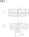
- (a) in FIG. 2 is a diagram when viewed in a direction of the optical axis of the objective lens 125
- (b) in FIG. 2 is a diagram when viewed in a direction perpendicular to the optical axis of the objective lens 125.
- a focusing state of the first split light C by the cylindrical lens 123 is also illustrated.
- the analysis unit 161 performs the correction process of subtracting ⁇ s (x) and ⁇ dev (t) from the phase image ⁇ (x, t) which is generated on the basis of the interference image, and performs a phase unwrapping process, so that the actual phase image ⁇ (x, t) can be obtained. Further, it is possible to obtain a phase image improved in an SN ratio even by subtracting any one of ⁇ s (x) and ⁇ dev (t) from the phase image ⁇ (x, t).
- the analysis unit 161 can perform a fixed pattern subtraction (subtraction of ⁇ s (x)), an offset subtraction (subtraction of ⁇ dev (t)), and a phase unwrapping in an arbitrary order, and can achieve the same result in any case. That is, any one of the following six orders may be used.
- the phase value obtained as a result of these processes may deviate from a predetermined range (for example, - ⁇ ⁇ ⁇ ⁇ ⁇ ) of 2 ⁇ width.
- a predetermined range for example, - ⁇ ⁇ ⁇ ⁇ ⁇ ⁇
- ⁇ (x, t) -2 (radian)
- ⁇ s (x) -1 (radian)
- ⁇ dev (t) -1 (radian)
- the result of the correction process can be kept to fall within the range of - ⁇ ⁇ ⁇ ⁇ ⁇ ⁇ .
- the fixed pattern subtraction and the offset subtraction may be performed by division in a complex domain. That is, when a phase ⁇ 2 is subtracted from a phase ⁇ 1 , as defined in the following Formula (6), a complex number C 1 of which the absolute value is 1 and the phase is ⁇ 1 , and a complex number C 2 of which the absolute value is 1 and the phase is ⁇ 2 are assumed. When dividing by the complex number C 2 , the complex number C 1 becomes as the following Formula (7).
- the procedure easy for intuitive understanding is the procedure (A) ("Phase unwrapping” ⁇ "Fixed pattern subtraction” ⁇ “Offset subtraction”) in which the phase unwrapping is performed first.
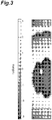
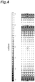
- FIG. 3 to FIG. 6 are diagrams illustrating an example of the phase image.
- the respective processes of the offset subtraction, the fixed pattern subtraction, and the phase unwrapping are performed in this order on the phase image (original phase image) generated on the basis of the interference image, and the corrected phase image after the phase unwrapping is generated.
- the horizontal direction represents time
- the vertical direction represents position in the width direction of the flow path 10.
- the fluid 20 is blood, and there is the CTC as the observation object 30 near the center of the respective drawings.
- FIG. 3 is a diagram illustrating the phase image (original phase image ⁇ (x, t)) before correction.
- the temporal noise and the spatial noise are overlapped with the actual phase image ⁇ (x, t) (Formula (5)), which corresponds to arg(C(x, t)) when being expressed by the complex domain as defined in Formula (10).
- FIG. 4 is a diagram illustrating a phase image ( ⁇ (x, t) - ⁇ dev (t)) after an offset subtraction.
- the phase image is obtained by subtracting the temporal noise from the original phase image ⁇ (x, t), which corresponds to arg(C(x, t)/C dev (t)) when being expressed by the complex domain.
- FIG. 5 is a diagram illustrating a phase image ( ⁇ (x, t) - ⁇ dev (t) - ⁇ s (x)) after a fixed pattern subtraction.
- the phase image is obtained by subtracting the temporal noise and the spatial noise from the original phase image ⁇ (x, t), which corresponds to Formula (11) when being expressed by the complex domain.
- the phase image corresponds to the actual phase image ⁇ (x, t) before the phase unwrapping.
- FIG. 6 is a diagram illustrating the actual phase image ⁇ (x, t) after the phase unwrapping.
- the shape of the observation object 30 can be recognized even in the original phase image ( FIG. 3 ), however, the shape of the observation object 30 can be clearly recognized in the phase image ( FIG. 4 ) after the offset subtraction and the phase image ( FIG. 5 ) after the fixed pattern subtraction. Further, in the actual phase image ( FIG. 6 ) after the phase unwrapping, the shape of the observation object 30 can be more clearly recognized.
- the two-dimensional phase image of the observation object 30 is generated by the analysis unit 161 on the basis of the detection signal output from the imaging unit 152, using the imaging unit 152 which receives the combined light and repeatedly outputs the detection signal indicating the one-dimensional interference image.
- the first split light is focused and incident on the focusing region which is long in a direction intersecting with the moving direction of the observation object 30 in the flow path 10 using the focusing optical element (for example, the cylindrical lens) disposed on the optical path of the first split light.
- the focusing optical element for example, the cylindrical lens
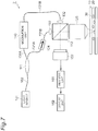
- FIG. 7 is a diagram illustrating a configuration of an observation apparatus 2 of a second embodiment.
- the second embodiment is a modification of the first embodiment.
- the observation apparatus 2 includes the light source 101, the optical fiber 102, the splitting unit 111, the combining unit 112, optical fibers 121A and 121B, the collimator 122, an optical isolator 124, the objective lens 125, optical fibers 131A and 131B, the collimator 132, the modulation unit 140, the imaging unit 152, the analysis unit 161, and the display unit 162.
- the light output from the light source 101 is guided by the optical fiber 102 to the splitting unit 111, and split by the splitting unit 111 to be the first split light and the second split light.
- the first split light output from the splitting unit 111 is guided by the optical fiber 121A to the optical isolator 124.
- the optical isolator 124 passes the light in a forward direction from the optical fiber 121A to the optical fiber 121B, but not passes the light in a reverse direction.
- the first split light passed through the optical isolator 124 is guided by the optical fiber 121B to the collimator 122, and is output from the collimator 122 to the combining unit 112 as parallel light of a predetermined beam diameter.
- the light passed through the combining unit 112 in the first split light which is output from the collimator 122 and input to the combining unit 112 is focused and incident on the observation object 30 in the flow path 10 by the objective lens 125.
- the bottom surface of the flow path 10 serves as a reflection surface.
- the first split light which is reflected on the reflection surface and input to the objective lens 125 is output from the objective lens 125 to the combining unit 112.
- the second split light output from the splitting unit 111 is guided by the optical fiber 131A to the modulation unit 140.
- the modulation unit 140 shifts the optical frequency of the second split light by ⁇ .
- the second split light output from the modulation unit 140 is guided by the optical fiber 131B to the collimator 132, and is output from the collimator 132 to the combining unit 112 as parallel light of a predetermined beam diameter.
- the first split light output from the objective lens 125 and the second split light output from the collimator 132 are combined by the combining unit 112.
- the combined light output from the combining unit 112 is received by the imaging unit 152.
- the detection signal indicating the one-dimensional interference image is repeatedly output at a predetermined line rate from the imaging unit 152.
- the detection signal repeatedly output from the imaging unit 152 is input to the analysis unit 161.
- the two-dimensional phase image of the observation object 30 is generated by the phase retrieval method on the basis of the one-dimensional interference image at each time point indicated by the detection signal. Further, the analysis unit 161 performs the correction process in order to reduce a temporal or spatial influence of noises in the phase image.
- part of the second split light output from the collimator 132 is reflected by the combining unit 112 and input to the collimator 122, but is blocked by the optical isolator 124, and thus is suppressed from returning to the light source 101.
- the cylindrical lens is inserted in the middle of the optical path of the first split light therebetween, so that the first split light is focused and incident on the focusing region which is long in a direction intersecting with the moving direction of the observation object 30 in the flow path 10.
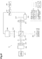
- FIG. 8 is a diagram illustrating a configuration of an observation apparatus 3 of a third embodiment.
- the observation apparatus 3 generates the phase image on the basis of the interference image of the observation object 30 which flows in the flow path 10 with the fluid 20.
- the flow path 10 is a flow cell
- the fluid 20 is blood
- the observation object 30 is a red blood cell, a white blood cell, a CTC, and the like.
- the observation apparatus 3 includes a light source 201, a collimator 202, a cylindrical lens 203, a spherical lens 204, a splitting-combining unit 210, a spherical lens 221, a cylindrical lens 231, a mirror 241, a linear motion stage 242, a spherical lens 251, an imaging unit 254, an analysis unit 261, and a display unit 262.
- a change of a light beam width in a direction parallel to the plane of paper is depicted with a solid line
- a change of the light beam width in a direction perpendicular to the plane of paper is depicted with a dashed line.
- the light source 201 outputs light.
- the light source 201 may output temporally and spatially coherent light, only the temporally coherent light, or only the spatially coherent light. Further, the light source 201 may output temporally and spatially incoherent light.
- the light source 201 is, for example, a laser light source, and specifically, a HeNe laser light source of 7 mW output power or the like is used.
- the collimator 202 collimates the light output from the light source 201 to output as parallel light of a predetermined beam diameter.
- the cylindrical lens 203 is a convex lens having a positive focal length.
- the cylindrical lens 203 inputs the light output from the collimator 202, and converges the light in the direction parallel to the plane of paper.
- the spherical lens 204 inputs the light output from the cylindrical lens 203, outputs the light as parallel light in the direction parallel to the plane of paper, and converges the light in the direction perpendicular to the plane of paper.
- the splitting-combining unit 210 inputs the light which is output from the light source 201 and arrives through the collimator 202, the cylindrical lens 203, and the spherical lens 204. Then, the splitting-combining unit 210 splits the input light into the first split light and the second split light, outputs the first split light to the flow path 10, and outputs the second split light to the mirror 241. Further, the splitting-combining unit 210 inputs the first split light which is reflected on the bottom surface of the flow path 10 and arrives, inputs the second split light which is reflected on the mirror 241 and arrives, combines the first split light and the second split light, and outputs the combined light to the imaging unit 254.
- the splitting-combining unit 210 serves as the splitting unit and the combining unit. An optical system of the first split light between the splitting-combining unit 210 and the flow path 10 and the like, and an optical system of the second split light between the splitting-combining unit 210 and the mirror 241 form a Michelson interferometer.
- the spherical lens 221 is an objective lens which is provided on the optical path of the first split light between the splitting-combining unit 210 and the flow path 10.
- the spherical lens 221 inputs the first split light output from the splitting-combining unit 210, converges the first split light in the direction parallel to the plane of paper, outputs the first split light as parallel light in the direction perpendicular to the plane of paper, and outputs the first split light to the flow path 10.
- the spherical lens 221 inputs the first split light which is reflected on the bottom surface of the flow path 10, and outputs the first split light to the splitting-combining unit 210.
- the cylindrical lens 231 is provided on the optical path of the second split light between the splitting-combining unit 210 and the mirror 241.
- the cylindrical lens 231 is a convex lens having a positive focal length.
- the cylindrical lens 231 inputs the second split light output from the splitting-combining unit 210, and outputs the second split light as parallel light to the mirror 241.
- the cylindrical lens 231 inputs the second split light which is reflected on the mirror 241, and outputs the second split light to the splitting-combining unit 210.
- the linear motion stage 242 moves the mirror 241 in a direction perpendicular to a reflection surface of the mirror 241. Since a Doppler shift occurs due to the movement of the mirror 241, the linear motion stage 242 shifts the optical frequency of the second split light. That is, the linear motion stage 242 is used as a modulation unit which temporally changes the phase difference by the frequency ⁇ between the first split light and the second split light at the combining by the splitting-combining unit 210.
- a Doppler shift amount ⁇ is defined by the following Formula (12).
- the mirror 241 may be moved at a constant speed V of about 15.8 mm/s by the linear motion stage 242.
- a disk having a gradient d (radian) formed along the circumference of a radius r may be rotated around the center position of the circle at an angular velocity ⁇ , and the second split light may be entered on the periphery of the circle to be reflected.
- the splitting-combining unit 210 inputs the first split light arriving from the spherical lens 221, inputs the second split light arriving from the cylindrical lens 231, and combines the first split light and the second split light to output the combined light to the spherical lens 251.
- the spherical lens 251 inputs the combined light output from the splitting-combining unit 210, converges the combined light in the direction parallel to the plane of paper, and the combined light is entered on a light receiving plane of the imaging unit 254 using the combined light as parallel light in the direction perpendicular to the plane of paper.
- the observation object 30 in the flow path 10 and the light receiving plane of the imaging unit 254 are in an imaging relation by the spherical lens 221 and the spherical lens 251 which are on the optical path therebetween.
- the imaging unit 254 is a photodetector which includes a plurality of pixels arranged in a direction intersecting with the moving direction of the image of the observation object 30 on the light receiving plane.
- an imaging region on which the linear focusing region is formed is a region long in a predetermined direction, and the plurality of pixels are arranged along the predetermined direction in the imaging region.
- the imaging unit 254 receives the combined light which is output from the splitting-combining unit 210 and arrives through the spherical lens 251, and repeatedly outputs a detection signal indicating a one-dimensional interference image at a predetermined line rate.
- the imaging unit 254 is, for example, a line sensor in which a plurality of pixels are disposed one-dimensionally. Further, the imaging unit 254 may be a two-dimensional sensor which is configured to read any one line of pixels arranged in a direction intersecting with the moving direction of the image of the observation object 30 on the light receiving plane.
- the description will be given assuming that the imaging unit 254 is a line sensor, however, in a case where the imaging unit 254 is a two-dimensional sensor, the above-described one-line pixels will be considered as a line sensor.
- the analysis unit 261 inputs the detection signal output repeatedly from the imaging unit 254, and generates the two-dimensional image on the basis of the one-dimensional interference image at each time point indicated by the detection signal.
- the analysis unit 261 generates, for example, the two-dimensional phase image of the observation object 30 as the two-dimensional image by the phase retrieval method (see Non Patent Documents 1 to 3) on the basis of the one-dimensional interference image at each time point.
- the phase retrieval method include a phase shift method, a Fourier transform method, and a Hilbert transform method.
- the analysis unit 261 generates the two-dimensional interference image on the basis of the plurality of one-dimensional interference images at a plurality of time points.
- the frequency ⁇ of the phase difference change by the Doppler shift is preferably 1/3 times the line rate of the imaging unit 254 or less. Further, the frequency ⁇ is preferably 1/4 times the line rate.
- the phase image is generated as already described in the first embodiment.
- the analysis unit 261 analyzes a shape (an external form, a shape of a nucleus, or the like) of the observation object 30 on the basis of the two-dimensional phase image to determine whether the observation object 30 is the CTC. Further, the analysis unit 261 preferably performs a correction process in order to reduce a temporal or spatial influence of noises in the phase image. The correction process is the same as already described in the first embodiment.
- the analysis unit 261 may be configured by a general-purpose computer, or may be configured by a dedicated device using, for example, a microcomputer or an FPGA. In a case where a dedicated device is used, the analysis unit 261 can generate and analyze the phase image at a high speed, and for example, the analysis unit can both input the detection signal from the imaging unit 254 and generate the phase image on the basis of the input detection signal in parallel in real time.
- the analysis unit 261 controls the linear motion stage 242 to move the mirror 241 in one direction during an exposure period of the imaging unit 254, and to move the mirror 241 in the reverse direction during a period of an A/D conversion and data transfer of the imaging unit 254.
- the display unit 262 is, for example, a display which displays the interference image and the phase image generated by the analysis unit 261, and displays an analysis result on the basis of the phase image by the analysis unit 261.
- the display unit 262 may make a sound or emit light to display the fact.
- FIG. 9 is a diagram illustrating a configuration of an observation apparatus 4 of a fourth embodiment.
- the fourth embodiment is a modification of the third embodiment.
- the observation apparatus 4 includes a spherical lens 205 on the optical path between the collimator 202 and the splitting-combining unit 210, a cylindrical lens 222 and a spherical lens 223 on the optical path of the first split light between the splitting-combining unit 210 and the flow path 10, a spherical lens 232 on the optical path of the second split light between the splitting-combining unit 210 and the mirror 241, and a cylindrical lens 252 and a spherical lens 253 on the optical path of the combined light between the splitting-combining unit 210 and the imaging unit 254.
- the change of the light beam width in the direction parallel to the plane of paper is depicted with a solid line
- the change of the light beam width in the direction perpendicular to the plane of paper is depicted with a dashed line.
- the spherical lens 205 inputs the light output from the collimator 202, and converges and outputs the light to the splitting-combining unit 210.
- the cylindrical lens 222 is a concave lens having a negative focal length.
- the cylindrical lens 222 inputs the first split light output from the splitting-combining unit 210, outputs the first split light as parallel light in the direction parallel to the plane of paper, and converges the first split light in the direction perpendicular to the plane of paper.
- the spherical lens 223 inputs the first split light output from the cylindrical lens 222, converges the first split light in the direction parallel to the plane of paper, outputs the first split light as parallel light in the direction perpendicular to the plane of paper, and outputs the first split light to the flow path 10.
- the spherical lens 223 and the cylindrical lens 222 input the first split light which is reflected on the bottom surface of the flow path 10, and output the first split light to the splitting-combining unit 210.
- the spherical lens 232 inputs the second split light output from the splitting-combining unit 210, and outputs the second split light as parallel light to the mirror 241.
- the spherical lens 232 inputs the second split light which is reflected on the mirror 241, and outputs the second split light to the splitting-combining unit 210.
- the splitting-combining unit 210 inputs the first split light which arrives from the cylindrical lens 222, inputs the second split light which arrives from the spherical lens 232, combines the first split light and the second split light, and outputs the combined light to the cylindrical lens 252.
- the cylindrical lens 252 is a convex lens having a positive focal length.
- the cylindrical lens 252 inputs the combined light output from the splitting-combining unit 210, outputs the combined light as parallel light in the direction parallel to the plane of paper, and diverges the combined light in the direction perpendicular to the plane of paper.
- the spherical lens 253 inputs the combined light output from the cylindrical lens 252, converges the combined light in the direction parallel to the plane of paper, and the combined light is entered on a light receiving plane of the imaging unit 254 using the combined light as parallel light in the direction perpendicular to the plane of paper.
- the observation object 30 in the flow path 10 and the light receiving plane of the imaging unit 254 are in an imaging relation by the spherical lens 223, the cylindrical lens 222, the cylindrical lens 252, and the spherical lens 253 which are on the optical path therebetween.
- the observation apparatus and the observation method according to the present invention are not limited to the above embodiments and configuration examples, and various modifications can be made.
- the observation apparatus is configured to observe an observation object moving in a flow path with a fluid, and include (1) a light source for outputting light, (2) an interference optical system for splitting the light into first split light and second split light, reflecting or transmitting the first split light by the observation object, and combining the first split light and the second split light to output combined light, (3) a modulation unit for temporally changing a phase difference between the first split light and the second split light at the combining, (4) an imaging unit including a plurality of pixels arranged in a direction intersecting with a moving direction of an image of the observation object on a light receiving plane on which the image of the observation object is formed, and for receiving the combined light to repeatedly output a detection signal indicating a one-dimensional interference image, and (5) an analysis unit for generating a two-dimensional image of the observation object on the basis of the detection signal.
- the interference optical system may include a focusing optical element on an optical path of the first split light for performing focused irradiation of the first split light such that a focusing region of the first split light becomes longer in the direction intersecting with the moving direction than in the moving direction of the observation object.
- the focusing optical element may be a cylindrical lens.
- the interference optical system may include a focusing optical element on an optical path of the second split light similar to the focusing optical element provided on the optical path of the first split light.
- the modulation unit may temporally change the phase difference at a frequency of 1/3 times a line rate of the imaging unit or less. Further, in the observation apparatus, the modulation unit may temporally change the phase difference by setting an optical frequency different between the first split light and the second split light. Further, in the observation apparatus, the modulation unit may include an acousto-optical element. Further, in the observation apparatus, the modulation unit may temporally change the phase difference by causing a Doppler shift in the first split light or the second split light.
- the analysis unit may generate a two-dimensional phase image as the two-dimensional image. Further, in the observation apparatus, the analysis unit may subtract data obtained from a region without the observation object in the flow path from the two-dimensional image so as to reduce a spatial noise from the two-dimensional image. Further, in the observation apparatus, the analysis unit may subtract a temporal variation component obtained from an image of a region in which the observation object does not pass through in the flow path in the two-dimensional image from the two-dimensional image so as to reduce a temporal noise from the two-dimensional image.
- the observation method is configured to observe an observation object moving in a flow path with a fluid, and include (1) a step of outputting light, (2) a step of splitting the light into first split light and second split light, (3) a step of reflecting or transmitting the first split light by the observation object, (4) a modulation step of temporally changing a phase difference between the first split light and the second split light, (5) a detection step of receiving combined light of the first split light and the second split light by an imaging unit to repeatedly output a detection signal indicating a one-dimensional interference image in a direction intersecting with a moving direction of an image of the observation object on a light receiving plane of the imaging unit on which the image of the observation object is formed, and (6) an analysis step of generating a two-dimensional image of the observation object on the basis of the detection signal.
- the phase difference in the modulation step, may be temporally changed at a frequency of 1/3 times a line rate of the imaging unit or less. Further, in the observation method, in the modulation step, the phase difference may be temporally changed by setting an optical frequency different between the first split light and the second split light. Further, in the observation method, in the analysis step, a two-dimensional phase image may be generated as the two-dimensional image.
- data obtained from a region without the observation object in the flow path may be subtracted from the two-dimensional image so as to reduce a spatial noise from the two-dimensional image.
- a temporal variation component obtained from an image of a region in which the observation object does not pass through in the flow path in the two-dimensional image may be subtracted from the two-dimensional image so as to reduce a temporal noise from the two-dimensional image.
- the present invention may be used as an observation apparatus and an observation method which can easily generate an excellent two-dimensional image of an observation object moving in a flow path with a fluid.
Landscapes
- Chemical & Material Sciences (AREA)
- Physics & Mathematics (AREA)
- Health & Medical Sciences (AREA)
- Life Sciences & Earth Sciences (AREA)
- Analytical Chemistry (AREA)
- Biochemistry (AREA)
- General Health & Medical Sciences (AREA)
- General Physics & Mathematics (AREA)
- Immunology (AREA)
- Pathology (AREA)
- Dispersion Chemistry (AREA)
- Investigating Or Analysing Materials By Optical Means (AREA)
Abstract
Description
- An aspect of the present invention relates to an observation apparatus and an observation method which observes an observation object moving in a flow path with a fluid.
- Inventions of an observation apparatus which generates a phase image on the basis of an interference image of an observation object flowing in a flow path with a fluid are disclosed in
Patent Documents 1 to 3. For example, the flow path is a flow cell, the fluid is blood, and the observation object is a red blood cell, a white blood cell, a circulating tumor cell (hereinafter, referred to as "CTC") in the blood, and the like. The CTC is a cell which is separated from a primary tumor tissue or a metastatic tumor tissue and enters the blood, and is found infinitesimally in peripheral blood of a solid cancer patient, and is involved in metastasis. - In recent years, the CTC has been actively studied. In clinical application fields, it has been reported that there is a certain relation between the number of CTCs per unit blood volume and a survival rate of a patient after certain years. Identifying and inspecting the circulating tumor cell are very useful to prognostic prediction of cancer, determination on chemotherapeutic efficacy, screening of cancer, gene therapy, and drug development support for anticancer agent or the like, and is very valuable to the clinical applications.
- An object can generally be identified on the basis of size, shape, or color. However, the white blood cell and the CTC are not so different in size, and both are colorless and transparent, and therefore, both cells are hard to be identified from an image obtained by a bright field microscope. Further, a phase contrast microscope and a differential interference microscope are used to visualize a colorless and transparent cell, but there is a defect in quantitativity with respect to an optical thickness. Further, the focal depth of these microscopes is equal to or less than a thickness of the cell depending on a using objective lens, and therefore, only two-dimensional information can be obtained even though the cell is structured three-dimensionally, and thus the object is not possible to be identified.
- In the observation apparatuses of the inventions disclosed in
Patent Documents 1 to 3, the phase image is generated on the basis of the interference image of the observation object which flows in the flow path with the fluid, and a shape (an external form, a shape of a nucleus, or the like) of the observation object is analyzed on the basis of the phase image, and therefore, the CTC in the blood can be identified. The conventional observation apparatus splits light output from a light source into first split light and second split light, reflects or transmits the first split light by the observation object in the flow path, causes interference between the first split light and the second split light to repeatedly acquire two-dimensional interference images, and generates the phase image of the observation object on the basis of these two-dimensional interference images. In order to acquire the two-dimensional interference image, the conventional observation apparatus uses an imaging unit having a plurality of pixels two-dimensionally arranged on an imaging plane. -
- Patent Document 1: Japanese Patent Publication No.
5022274 - Patent Document 2: Japanese Patent Publication No.
5364203 - Patent Document 3: International Publication
WO 2013/065796 -
- Non Patent Document 1: Daniel Malacara, et al., "Interferogram Analysis for Optical Testing", Taylor & Francis Group, Second Edition, Chapter 6 (2005)
- Non Patent Document 2: P. Hariharan, et al., "Digital phase-shifting interferometry: a simple error-compensating phase calculation algorithm", Appl. Opt. 26, pp. 2504-2506 (1987)
- Non Patent Document 3: Kenichi Hibino, et al., "Phase-shifting algorithms for nonlinear and spatially nonuniform phase shifts", J. Opt. Soc. Am. A 14, pp. 918-930 (1997)
- In the above-described observation apparatus, the observation objects flow in the flow path continuously. Therefore, in the conventional observation apparatus, particularly in a case where a moving speed of the observation object is not constant, an image of the observation object may be partially damaged between continuous two two-dimensional interference images in a plurality of two-dimensional interference images acquired by the imaging unit, and in that case, the partially damaged portion of the image is not possible to be recovered even when being subjected to image processing. In such a case, the observation object is hard to be identified.
- Further, when generating the phase image on the basis of the interference image, there is a need to acquire a plurality of two-dimensional interference images in a period when the observation object seems to be stopped. The conventional observation apparatus also has a problem derived from this.
- That is, general operations when acquiring one image by the imaging unit is roughly divided into three steps, exposure, A/D conversion, and data transfer. When a plurality of images are acquired by the imaging unit, these three steps are repeatedly performed. The imaging unit which acquires a two-dimensional image needs a long time for the A/D conversion step and the data transfer step. Therefore, since it takes a long time until the next image is acquired after an image is acquired by the imaging unit, it is difficult to acquire the plurality of two-dimensional interference images in a period when the observation object seems to be stopped so as to generate the phase image, and accordingly, it is difficult to identify the observation object.
- An aspect of the present invention has been made in order to solve the above problem, and an object thereof is to provide an observation apparatus and an observation method which can easily generate an excellent two-dimensional image of the observation object moving in a flow path with a fluid.
- An observation apparatus according to an aspect of the present invention is an observation apparatus for observing an observation object moving in a flow path with a fluid, and includes (1) a light source for outputting light; (2) an interference optical system for splitting the light into first split light and second split light, reflecting or transmitting the first split light by the observation object, and combining the first split light and the second split light to output combined light; (3) a modulation unit for temporally changing a phase difference between the first split light and the second split light at the combining; (4) an imaging unit including a plurality of pixels arranged in a direction intersecting with a moving direction of an image of the observation object on a light receiving plane on which the image of the observation object is formed, and for receiving the combined light to repeatedly output a detection signal indicating a one-dimensional interference image; and (5) an analysis unit for generating a two-dimensional image of the observation object on the basis of the detection signal.
- An observation method according to an aspect of the present invention is an observation method of observing an observation object moving in a flow path with a fluid, and includes (1) a step of outputting light; (2) a step of splitting the light into first split light and second split light; (3) a step of reflecting or transmitting the first split light by the observation object; (4) a modulation step of temporally changing a phase difference between the first split light and the second split light; (5) a detection step of receiving combined light of the first split light and the second split light by an imaging unit to repeatedly output a detection signal indicating a one-dimensional interference image in a direction intersecting with a moving direction of an image of the observation object on a light receiving plane of the imaging unit on which the image of the observation object is formed; and (6) an analysis step of generating a two-dimensional image of the observation object on the basis of the detection signal.
- According to the present invention, it is possible to easily generate an excellent two-dimensional image of an observation object which moves in a flow path with a fluid.
-
-
FIG. 1 is a diagram illustrating a configuration of anobservation apparatus 1 of a first embodiment. -
FIG. 2 includes (a), (b) diagrams for describing aflow path 10. -
FIG. 3 is a diagram illustrating a phase image (original phase image φ(x, t)) before correction. -
FIG. 4 is a diagram illustrating a phase image after an offset subtraction. -
FIG. 5 is a diagram illustrating a phase image after a fixed pattern subtraction. -
FIG. 6 is a diagram illustrating an actual phase image Φ(x, t) after phase unwrapping. -
FIG. 7 is a diagram illustrating a configuration of anobservation apparatus 2 of a second embodiment. -
FIG. 8 is a diagram illustrating a configuration of anobservation apparatus 3 of a third embodiment. -
FIG. 9 is a diagram illustrating a configuration of anobservation apparatus 4 of a fourth embodiment. - Hereinafter, embodiments for carrying out the present invention will be described in detail with reference to the accompanying drawings. In the description of the drawings, the same elements will be denoted by the same reference signs, without redundant description. Further, the present invention is not limited to these examples.
-
FIG. 1 is a diagram illustrating a configuration of anobservation apparatus 1 of a first embodiment. Theobservation apparatus 1 generates a phase image on the basis of an interference image of anobservation object 30 which flows in aflow path 10 with afluid 20. For example, theflow path 10 is a flow cell, thefluid 20 is blood, and theobservation object 30 is a red blood cell, a white blood cell, a CTC, and the like. - The
observation apparatus 1 includes alight source 101, anoptical fiber 102, asplitting unit 111, a combiningunit 112, anoptical fiber 121, acollimator 122, acylindrical lens 123, anobjective lens 125, anoptical fiber 131, acollimator 132, acylindrical lens 133, amirror 134, anobjective lens 135, amodulation unit 140, alens 151, animaging unit 152, ananalysis unit 161, and adisplay unit 162. - The
light source 101 outputs light. Thelight source 101 may output temporally and spatially coherent light, only the temporally coherent light, or only the spatially coherent light. Further, thelight source 101 may output temporally and spatially incoherent light. Thelight source 101 is, for example, a laser light source, and specifically, a HeNe laser light source of 7 mW output power or the like is used. - The
optical fiber 102 is used to optically couple thelight source 101 and thesplitting unit 111, and guides the light output from thelight source 101 to thesplitting unit 111. Thesplitting unit 111 splits the light output from theoptical fiber 102 into two components, and outputs as first split light and second split light. Thesplitting unit 111 may be, for example, a half mirror, or may be a fiber coupler. An interference optical system from thesplitting unit 111 to the combiningunit 112 forms a Mach-Zehnder interferometer. - The
optical fiber 121, thecollimator 122, thecylindrical lens 123, and theobjective lens 125 are provided on an optical path of the first split light from thesplitting unit 111 to the combiningunit 112. Further, theflow path 10 is disposed to be intersected with the first optical path. - The
optical fiber 121 is used to optically couple thesplitting unit 111 and thecollimator 122, and guides the first split light output from thesplitting unit 111 to thecollimator 122. Thecollimator 122 inputs the first split light output from theoptical fiber 121, and collimates the first split light to output as parallel light of a predetermined beam diameter. - The
cylindrical lens 123 is a focusing optical element which performs focused irradiation of the first split light to a focusing region which is longer in a direction intersecting with a moving direction than in the moving direction of theobservation object 30 in theflow path 10. Thecylindrical lens 123 inputs the first split light output from thecollimator 122, and focuses the first split light with respect to the moving direction of theobservation object 30. The focusing region is a linear region intersecting with the moving direction of theobservation object 30 in theflow path 10. Theobjective lens 125 inputs the first split light transmitting the fluid 20 and theobservation object 30 moving in theflow path 10, and outputs the first split light to the combiningunit 112. - The
optical fiber 131, thecollimator 132, thecylindrical lens 133, themirror 134, and theobjective lens 135 are provided on an optical path of the second split light from thesplitting unit 111 to the combiningunit 112. Further, acousto-optical elements - The
optical fiber 131 is used to optically couple thesplitting unit 111 and thecollimator 132, and guides the second split light output from thesplitting unit 111 to thecollimator 132. Thecollimator 132 inputs the second split light output from theoptical fiber 131, and collimates the second split light to output as parallel light of a predetermined beam diameter. - The
cylindrical lens 133 is a focusing optical element which performs focused irradiation of the second split light to the focusing region long in one direction. Thecylindrical lens 133 inputs the second split light which is output from thecollimator 132 and reaches through the acousto-optical elements mirror 134. The focusing region is a linear region long in one direction. Theobjective lens 135 inputs the second split light which is output from thecylindrical lens 133 and reflected on themirror 134, and outputs the second split light to the combiningunit 112. - The combining
unit 112 inputs the first split light output from theobjective lens 125, inputs the second split light output from theobjective lens 135, combines the first split light and the second split light, and outputs the combined light to thelens 151. The combiningunit 112 is, for example, a half mirror. - The
collimator 132, thecylindrical lens 133, and theobjective lens 135 provided on the optical path of the second split light are preferably the same as thecollimator 122, thecylindrical lens 123, and theobjective lens 125 provided on the optical path of the first split light. With such a configuration, even in a case where thelight source 101 outputs temporally incoherent light, the interference between the first split light and the second split light combined by the combiningunit 112 can be increased. - As a focusing optical element which focuses light to a linear region long in one direction, a Fresnel biprism, a Fresnel zone plate, an axicon lens, a holographic optical element, and a spatial light modulator may be used besides the cylindrical lens.
- The
modulation unit 140 includes the acousto-optical elements unit 112. The acousto-optical element 141 of the former stage inputs a sinusoidal electric signal of a frequency Ω0 to form a diffraction grating, inputs the second split light output from thecollimator 132, and diffracts the second split light by the diffraction grating to output +1 order diffracted light. The acousto-optical element 142 of the latter stage inputs a sinusoidal electric signal of a frequency (Ω0 + Ω) to form a diffraction grating, inputs the +1 order diffracted light of the second split light output from the acousto-optical element 141, and diffracts the second split light by the diffraction grating to output -1 order diffracted light. - The -1 order diffracted light of the second split light output from the acousto-
optical element 142 has an optical frequency which is shifted by the frequency Ω with respect to an optical frequency of the first split light. For example, Ω0 is 200 MHz, and Ω is 20 kHz. - Even when the acousto-
optical element 141 outputs the -1 order diffracted light, and the acousto-optical element 142 outputs the +1 order diffracted light, the +1 order diffracted light of the second split light output from the acousto-optical element 142 similarly can have the optical frequency shifted by the frequency Ω with respect to the optical frequency of the first split light. - In this way, the
modulation unit 140 including the acousto-optical elements unit 112, and therefore, the phase difference between the first split light and the second split light can be temporally changed by the frequency Ω. - Here, the acousto-
optical elements unit 112 is not limited to the configuration in which the acousto-optical element is included. - The
lens 151 inputs the combined light output from the combiningunit 112, and causes the combined light to be incident on a light receiving plane of theimaging unit 152. Theobservation object 30 in theflow path 10 and the light receiving plane of theimaging unit 152 are in an imaging relation by theobjective lens 125 and thelens 151 on the optical path therebetween. - The
imaging unit 152 is a photodetector which includes a plurality of pixels arranged in a direction intersecting with the moving direction of an image of theobservation object 30 on the light receiving plane. On the light receiving plane, an imaging region on which the linear focusing region by thecylindrical lens 123 is imaged is a region long in a predetermined direction, and the plurality of pixels are arranged along the predetermined direction in the imaging region. Theimaging unit 152 receives the combined light which is output from the combiningunit 112 and arrives through thelens 151, and repeatedly outputs a detection signal indicating a one-dimensional interference image at a predetermined line rate. - The
imaging unit 152 is, for example, a line sensor in which a plurality of pixels are disposed one-dimensionally. Further, theimaging unit 152 may be a two-dimensional sensor which is configured to read any one line of pixels arranged in a direction intersecting with the moving direction of the image of theobservation object 30 on the light receiving plane. Hereinbelow, the description will be given assuming that theimaging unit 152 is a line sensor, however, in a case where theimaging unit 152 is a two-dimensional sensor, the above-described one-line pixels will be considered as a line sensor. - The
analysis unit 161 inputs the detection signal output repeatedly from theimaging unit 152, and generates a two-dimensional image on the basis of the one-dimensional interference image at each time point indicated by the detection signal. Theanalysis unit 161 generates, for example, a two-dimensional phase image of theobservation object 30 as the two-dimensional image by a phase retrieval method (see Non Patent Documents 1 to 3) on the basis of the one-dimensional interference image at each time point. Examples of the phase retrieval method include a phase shift method, a Fourier transform method, and a Hilbert transform method. Further, for example, theanalysis unit 161 generates the two-dimensional interference image on the basis of a plurality of one-dimensional interference images at a plurality of time points. - In order for the
analysis unit 161 to generate the phase image with a high accuracy on the basis of the interference image, the frequency Ω of the phase difference change by the modulation unit 140 (the acousto-optical elements 141 and 142) is preferably 1/3 times the line rate of theimaging unit 152 or less. Further, the frequency Ω is preferably 1/4 times the line rate. - The
analysis unit 161 analyzes a shape (an external form, a shape of a nucleus, or the like) of theobservation object 30 on the basis of the two-dimensional phase image to determine whether theobservation object 30 is the CTC. Further, theanalysis unit 161 preferably performs a correction process in order to reduce a temporal or spatial influence of noises in the phase image. - For example, the
analysis unit 161 may be configured by a general-purpose computer. The computer is configured by a CPU (central processing unit) which is a processor, a RAM (random access memory) or a ROM (read only memory) which is a recording medium, an input unit such as a keyboard and a mouse, and an input-output module. The computer reads a program and the like on hardware such as the CPU and the RAM, causes the CPU to perform generation of the phase image on the basis of the detection signal from theimaging unit 152 and the like, and reads and writes the data in the RAM. Further, theanalysis unit 161 may be configured by a dedicated device using, for example, a microcomputer and an FPGA (field programmable gate array). In a case where a dedicated device is used, theanalysis unit 161 can generate and analyze the phase image at a high speed. For example, the analysis unit can both input the detection signal from theimaging unit 152 and generate the phase image on the basis of the input detection signal in parallel in real time. - The
display unit 162 is, for example, a display, which displays the interference image and the phase image generated by theanalysis unit 161, and displays an analysis result on the basis of the phase image by theanalysis unit 161. When theanalysis unit 161 determines that theobservation object 30 is the CTC, thedisplay unit 162 may make a sound or emit light to display the fact. - Next, the operation of the
observation apparatus 1 of the first embodiment will be described, and a processing content of theanalysis unit 161 will be described. - The light output from the
light source 101 is guided by theoptical fiber 102 to thesplitting unit 111, and split by thesplitting unit 111 to be the first split light and the second split light. - The first split light output from the
splitting unit 111 is guided by theoptical fiber 121 to thecollimator 122, and output as parallel light of a predetermined beam diameter from thecollimator 122. The first split light output from thecollimator 122 is focused and incident by thecylindrical lens 123 onto the focusing region which is long in a direction intersecting with the moving direction of theobservation object 30 in theflow path 10. The first split light which has transmitted the fluid 20 and theobservation object 30 is input to the combiningunit 112 through theobjective lens 125. - The second split light output from the
splitting unit 111 is guided by theoptical fiber 131 to thecollimator 132, and output as parallel light of a predetermined beam diameter from thecollimator 132. The second split light output from thecollimator 132 is shifted by an optical frequency Ω by themodulation unit 140, and focused to the focusing region which is long in one direction by thecylindrical lens 133. Further, the second split light is input to the combiningunit 112 through theobjective lens 135. - The first split light output from the
objective lens 125 and the second split light output from theobjective lens 135 are combined by the combiningunit 112. The combined light output from the combiningunit 112 is received by theimaging unit 152 through thelens 151. The detection signal indicating the one-dimensional interference image is repeatedly output at a predetermined line rate from theimaging unit 152. - The detection signal repeatedly output from the
imaging unit 152 is input to theanalysis unit 161. In theanalysis unit 161, the two-dimensional phase image of theobservation object 30 is generated by the phase retrieval method on the basis of the one-dimensional interference image at each time point indicated by the detection signal. Further, theanalysis unit 161 performs the correction process for reducing a temporal or spatial influence of noises in the phase image. - An example of a method for the
analysis unit 161 to generate the phase image by the phase retrieval method from the interference image is as follows. The detection signal output from theimaging unit 152 is denoted by I(xi, t). xi represents a position (pixel number i) in an arranging direction of the plurality of pixels in the light receiving plane of theimaging unit 152, and also represents a position in a direction intersecting with the moving direction of theobservation object 30 in theflow path 10. t represents a time point when the detection signal is output from theimaging unit 152, and also represents a position in the moving direction of theobservation object 30 in theflow path 10. Therefore, a detection signal I(xi, t) repeatedly output from theimaging unit 152 at a predetermined line rate represents a two-dimensional interference image. Therefore, the two-dimensional phase image can be generated by the phase retrieval method on the basis of the two-dimensional interference image. - For example, in a case where the phase shift method is used in the phase retrieval method and a line rate fline of the
imaging unit 152 is four times the optical frequency shift amount (a reciprocal of the period of a temporal change of the phase difference) Ω, a two-dimensional phase image φ(xi, t) can be generated by the following Formula (1) (Formula (1a) and Formula (1b)). t1 to t4 represent time points different from each other in the period when theobservation object 30 seems to be stopped, and satisfy t1 < t2 < t3 < t4. t represents a time point (for example, t = (t1 + t4)/2) representing the period. j represents an imaginary unit.
[Formula 1]

- When an arrangement pitch of the pixels intersecting with the moving direction of the image of the
observation object 30 on the light receiving plane of theimaging unit 152 is set to p, and a magnification when theobservation object 30 is imaged onto the light receiving plane of theimaging unit 152 is set to M, a resolution rx in the arrangement direction of the pixels on the light receiving plane of theimaging unit 152 is represented by the following Formula (2). Further, when a moving speed of theobservation object 30 in theflow path 10 is set to V, and the line rate of theimaging unit 152 is set to fline, a resolution ry in the moving direction of the image on the light receiving plane of theimaging unit 152 is represented by the following Formula (3). In order to set the resolutions to be equal in the x direction and the y direction in the two-dimensional phase image, theimaging unit 152 may operate at the line rate of fline defined in the following Formula (4).
[Formula 2]


- A method of correcting the phase image in the
analysis unit 161 is as follows. In general, a phase image φ(x, t) generated on the basis of the interference image is defined by the following Formula (5). Φ(x, t) represents an actual phase image. φs(x) represents phase data of a fixed pattern of a background. φdev(t) represents phase data of a temporal variation of an offset value.
[Formula 5]
- φs(x) indicates that spatial noises are overlapped with the actual phase image Φ(x, t), and is caused by a distortion of an optical wavefront due to the optical system and the flow path. With regard to φs(x), for example, the interference image in a state where the
observation object 30 does not flow in theflow path 10, or the interference image of a region without theobservation object 30 in a state where theobservation object 30 flows is acquired, and the phase image may be generated on the basis of the interference image. The phase image generated as described above becomes φs(x). - φdev(t) indicates that temporal noises are overlapped with the actual phase image Φ(x, t), and is caused by a vibration due to disturbance noises to the optical system. As illustrated in
FIG. 2 , there are reference regions B in theflow path 10 in which theobservation object 30 does not pass through on both sides of a measurement region A in which theobservation object 30 passes through, and therefore, φdev(t) can be obtained as a temporal variation component which is obtained from the phase image of the reference region B in the phase image φ(x, t). (a) inFIG. 2 is a diagram when viewed in a direction of the optical axis of theobjective lens 125, and (b) inFIG. 2 is a diagram when viewed in a direction perpendicular to the optical axis of theobjective lens 125. Further, in the drawing, a focusing state of the first split light C by thecylindrical lens 123 is also illustrated. - The
analysis unit 161 performs the correction process of subtracting φs(x) and φdev(t) from the phase image φ(x, t) which is generated on the basis of the interference image, and performs a phase unwrapping process, so that the actual phase image Φ(x, t) can be obtained. Further, it is possible to obtain a phase image improved in an SN ratio even by subtracting any one of φs(x) and φdev(t) from the phase image φ(x, t). - The
analysis unit 161 can perform a fixed pattern subtraction (subtraction of φs(x)), an offset subtraction (subtraction of φdev(t)), and a phase unwrapping in an arbitrary order, and can achieve the same result in any case. That is, any one of the following six orders may be used. - (A) "Phase unwrapping" ⇒ "Fixed pattern subtraction" ⇒ "Offset subtraction"
- (B) "Phase unwrapping" ⇒ "Offset subtraction" ⇒ "Fixed pattern subtraction"
- (C) "Fixed pattern subtraction" ⇒ "Phase unwrapping" ⇒ "Offset subtraction"
- (D) "Fixed pattern subtraction" ⇒ "Offset subtraction" ⇒ "Phase unwrapping"
- (E) "Offset subtraction" ⇒ "Phase unwrapping" ⇒ "Fixed pattern subtraction"
- (F) "Offset subtraction" ⇒ "Fixed pattern subtraction" ⇒ "Phase unwrapping"
- Here, in any case, in the fixed pattern subtraction performed after the phase unwrapping, there is a need to use φs(x) which has been phase unwrapped in advance. Further, in the offset subtraction performed after the phase unwrapping, there is a need to use φdev(t) which has been phase unwrapped in advance.
- On the other hand, in the fixed pattern subtraction and the offset subtraction performed before the phase unwrapping, the phase value obtained as a result of these processes may deviate from a predetermined range (for example, -π ≤ φ < π) of 2π width. For example, assuming φ(x, t) = -2 (radian), φs(x) = -1 (radian), and φdev(t) = -1 (radian), Φ(x, t) = -4 (radian) is obtained as a result of the correction process, and deviated from the range of -π ≤ φ < π. In that case, by using a modulo operator, the result of the correction process can be kept to fall within the range of -π ≤ φ < π.
- In order to perform the correction process while keeping the phase range in -π ≤ φ < π, the fixed pattern subtraction and the offset subtraction may be performed by division in a complex domain. That is, when a phase φ2 is subtracted from a phase φ1, as defined in the following Formula (6), a complex number C1 of which the absolute value is 1 and the phase is φ1, and a complex number C2 of which the absolute value is 1 and the phase is φ2 are assumed. When dividing by the complex number C2, the complex number C1 becomes as the following Formula (7). Then, as a phase as a result of the division, a value obtained by subtracting the phase φ2 from the phase φ1 can be uniquely obtained as defined in the following Formula (8).
[Formula 6]


- Similarly, when the correction process of the following Formula (9) is performed, complex numbers C(x, t), Cs(x), and Cdev(t) defined in the following Formula (10) are assumed for φ(x, t), φs(x), and φdev(t) respectively. As a result, the actual phase image Φ(x, t) before the phase unwrapping can be uniquely obtained from the following Formula (11).
[Formula 9]


- In this way, as an advantage of subtracting the phases by the division in the complex domain, in a case where the original data of the phase calculation is given as a complex number having an argument of the phase, instead of the phase, the number of calculation steps can be reduced, and the calculation can be performed at a high speed. For example, in the case of the phase shift method of four points as defined in Formula (1), φ is expressed as the argument of Z(x, t) of Formula (1b). When an electronic computer is used, the calculation of the argument, that is, arc tangent, takes a long time. However, when the phase value is used for the first time immediately before the phase unwrapping while the obtained phase data is used as the complex number itself, the time-consuming calculation of the arc tangent can be completed at a time, and the calculation can be performed at a high speed by Formula (11).
- As a procedure of obtaining the actual phase image Φ(x, t), the procedure easy for intuitive understanding is the procedure (A) ("Phase unwrapping" ⇒ "Fixed pattern subtraction" ⇒ "Offset subtraction") in which the phase unwrapping is performed first. The procedure easy for the electronic computer is the procedure (F) ("Offset subtraction" => "Fixed pattern subtraction" ⇒ "Phase unwrapping") in which the calculation of the argument and the phase unwrapping are performed last.
-
FIG. 3 to FIG. 6 are diagrams illustrating an example of the phase image. Herein, the respective processes of the offset subtraction, the fixed pattern subtraction, and the phase unwrapping are performed in this order on the phase image (original phase image) generated on the basis of the interference image, and the corrected phase image after the phase unwrapping is generated. In these drawings, the horizontal direction represents time, and the vertical direction represents position in the width direction of theflow path 10. The fluid 20 is blood, and there is the CTC as theobservation object 30 near the center of the respective drawings. -
FIG. 3 is a diagram illustrating the phase image (original phase image φ(x, t)) before correction. In the phase image φ(x, t), the temporal noise and the spatial noise are overlapped with the actual phase image Φ(x, t) (Formula (5)), which corresponds to arg(C(x, t)) when being expressed by the complex domain as defined in Formula (10). -
FIG. 4 is a diagram illustrating a phase image (φ(x, t) - φdev(t)) after an offset subtraction. The phase image is obtained by subtracting the temporal noise from the original phase image φ(x, t), which corresponds to arg(C(x, t)/Cdev(t)) when being expressed by the complex domain. -
FIG. 5 is a diagram illustrating a phase image (φ(x, t) - φdev(t) - φs(x)) after a fixed pattern subtraction. The phase image is obtained by subtracting the temporal noise and the spatial noise from the original phase image φ(x, t), which corresponds to Formula (11) when being expressed by the complex domain. The phase image corresponds to the actual phase image Φ(x, t) before the phase unwrapping. -
FIG. 6 is a diagram illustrating the actual phase image Φ(x, t) after the phase unwrapping. As can be seen from these drawings, the shape of theobservation object 30 can be recognized even in the original phase image (FIG. 3 ), however, the shape of theobservation object 30 can be clearly recognized in the phase image (FIG. 4 ) after the offset subtraction and the phase image (FIG. 5 ) after the fixed pattern subtraction. Further, in the actual phase image (FIG. 6 ) after the phase unwrapping, the shape of theobservation object 30 can be more clearly recognized. - As described above, in the present embodiment, the two-dimensional phase image of the
observation object 30 is generated by theanalysis unit 161 on the basis of the detection signal output from theimaging unit 152, using theimaging unit 152 which receives the combined light and repeatedly outputs the detection signal indicating the one-dimensional interference image. With this configuration, it is possible to easily generate an excellent phase image of theobservation object 30 which flows in theflow path 10 with the fluid 20. - Further, in the present embodiment, the first split light is focused and incident on the focusing region which is long in a direction intersecting with the moving direction of the
observation object 30 in theflow path 10 using the focusing optical element (for example, the cylindrical lens) disposed on the optical path of the first split light. With this configuration, the light emitted to other than the observation line is reduced while increasing the intensity of the first split light, so that it is possible to suppress stray light, and it is possible to obtain the phase image with high accuracy. Further, it is possible to obtain the phase image with high accuracy by performing the correction to reduce the spatial noises from the two-dimensional phase image or the correction to reduce the temporal noises from the two-dimensional phase image. -
FIG. 7 is a diagram illustrating a configuration of anobservation apparatus 2 of a second embodiment. The second embodiment is a modification of the first embodiment. Theobservation apparatus 2 includes thelight source 101, theoptical fiber 102, thesplitting unit 111, the combiningunit 112,optical fibers collimator 122, anoptical isolator 124, theobjective lens 125,optical fibers collimator 132, themodulation unit 140, theimaging unit 152, theanalysis unit 161, and thedisplay unit 162. - In the present embodiment, the light output from the
light source 101 is guided by theoptical fiber 102 to thesplitting unit 111, and split by thesplitting unit 111 to be the first split light and the second split light. - The first split light output from the
splitting unit 111 is guided by theoptical fiber 121A to theoptical isolator 124. Theoptical isolator 124 passes the light in a forward direction from theoptical fiber 121A to theoptical fiber 121B, but not passes the light in a reverse direction. The first split light passed through theoptical isolator 124 is guided by theoptical fiber 121B to thecollimator 122, and is output from thecollimator 122 to the combiningunit 112 as parallel light of a predetermined beam diameter. - The light passed through the combining
unit 112 in the first split light which is output from thecollimator 122 and input to the combiningunit 112 is focused and incident on theobservation object 30 in theflow path 10 by theobjective lens 125. The bottom surface of theflow path 10 serves as a reflection surface. The first split light which is reflected on the reflection surface and input to theobjective lens 125 is output from theobjective lens 125 to the combiningunit 112. - The second split light output from the
splitting unit 111 is guided by theoptical fiber 131A to themodulation unit 140. Themodulation unit 140 shifts the optical frequency of the second split light by Ω. The second split light output from themodulation unit 140 is guided by theoptical fiber 131B to thecollimator 132, and is output from thecollimator 132 to the combiningunit 112 as parallel light of a predetermined beam diameter. - The first split light output from the
objective lens 125 and the second split light output from thecollimator 132 are combined by the combiningunit 112. The combined light output from the combiningunit 112 is received by theimaging unit 152. The detection signal indicating the one-dimensional interference image is repeatedly output at a predetermined line rate from theimaging unit 152. - The detection signal repeatedly output from the
imaging unit 152 is input to theanalysis unit 161. In theanalysis unit 161, the two-dimensional phase image of theobservation object 30 is generated by the phase retrieval method on the basis of the one-dimensional interference image at each time point indicated by the detection signal. Further, theanalysis unit 161 performs the correction process in order to reduce a temporal or spatial influence of noises in the phase image. - Here, part of the second split light output from the
collimator 132 is reflected by the combiningunit 112 and input to thecollimator 122, but is blocked by theoptical isolator 124, and thus is suppressed from returning to thelight source 101. - In the present embodiment, only the first split light in the first split light and the second split light is propagated between the combining
unit 112 and theflow path 10. The cylindrical lens is inserted in the middle of the optical path of the first split light therebetween, so that the first split light is focused and incident on the focusing region which is long in a direction intersecting with the moving direction of theobservation object 30 in theflow path 10. - Even in the second embodiment, similarly to the case of the first embodiment, it is possible to easily generate an excellent phase image of the
observation object 30 which flows in theflow path 10 with the fluid 20. -
FIG. 8 is a diagram illustrating a configuration of anobservation apparatus 3 of a third embodiment. Theobservation apparatus 3 generates the phase image on the basis of the interference image of theobservation object 30 which flows in theflow path 10 with the fluid 20. For example, theflow path 10 is a flow cell, the fluid 20 is blood, and theobservation object 30 is a red blood cell, a white blood cell, a CTC, and the like. - The
observation apparatus 3 includes alight source 201, acollimator 202, acylindrical lens 203, aspherical lens 204, a splitting-combiningunit 210, aspherical lens 221, acylindrical lens 231, amirror 241, alinear motion stage 242, aspherical lens 251, animaging unit 254, ananalysis unit 261, and adisplay unit 262. In the drawing, a change of a light beam width in a direction parallel to the plane of paper is depicted with a solid line, and a change of the light beam width in a direction perpendicular to the plane of paper is depicted with a dashed line. - The
light source 201 outputs light. Thelight source 201 may output temporally and spatially coherent light, only the temporally coherent light, or only the spatially coherent light. Further, thelight source 201 may output temporally and spatially incoherent light. Thelight source 201 is, for example, a laser light source, and specifically, a HeNe laser light source of 7 mW output power or the like is used. - The
collimator 202 collimates the light output from thelight source 201 to output as parallel light of a predetermined beam diameter. - The
cylindrical lens 203 is a convex lens having a positive focal length. Thecylindrical lens 203 inputs the light output from thecollimator 202, and converges the light in the direction parallel to the plane of paper. - The
spherical lens 204 inputs the light output from thecylindrical lens 203, outputs the light as parallel light in the direction parallel to the plane of paper, and converges the light in the direction perpendicular to the plane of paper. - The splitting-combining
unit 210 inputs the light which is output from thelight source 201 and arrives through thecollimator 202, thecylindrical lens 203, and thespherical lens 204. Then, the splitting-combiningunit 210 splits the input light into the first split light and the second split light, outputs the first split light to theflow path 10, and outputs the second split light to themirror 241. Further, the splitting-combiningunit 210 inputs the first split light which is reflected on the bottom surface of theflow path 10 and arrives, inputs the second split light which is reflected on themirror 241 and arrives, combines the first split light and the second split light, and outputs the combined light to theimaging unit 254. The splitting-combiningunit 210 serves as the splitting unit and the combining unit. An optical system of the first split light between the splitting-combiningunit 210 and theflow path 10 and the like, and an optical system of the second split light between the splitting-combiningunit 210 and themirror 241 form a Michelson interferometer. - The
spherical lens 221 is an objective lens which is provided on the optical path of the first split light between the splitting-combiningunit 210 and theflow path 10. Thespherical lens 221 inputs the first split light output from the splitting-combiningunit 210, converges the first split light in the direction parallel to the plane of paper, outputs the first split light as parallel light in the direction perpendicular to the plane of paper, and outputs the first split light to theflow path 10. Thespherical lens 221 inputs the first split light which is reflected on the bottom surface of theflow path 10, and outputs the first split light to the splitting-combiningunit 210. - The
cylindrical lens 231 is provided on the optical path of the second split light between the splitting-combiningunit 210 and themirror 241. Thecylindrical lens 231 is a convex lens having a positive focal length. Thecylindrical lens 231 inputs the second split light output from the splitting-combiningunit 210, and outputs the second split light as parallel light to themirror 241. Thecylindrical lens 231 inputs the second split light which is reflected on themirror 241, and outputs the second split light to the splitting-combiningunit 210. - The
linear motion stage 242 moves themirror 241 in a direction perpendicular to a reflection surface of themirror 241. Since a Doppler shift occurs due to the movement of themirror 241, thelinear motion stage 242 shifts the optical frequency of the second split light. That is, thelinear motion stage 242 is used as a modulation unit which temporally changes the phase difference by the frequency Ω between the first split light and the second split light at the combining by the splitting-combiningunit 210. - When a moving speed of the
mirror 241 is set to V, and a light wavelength is set to λ, a Doppler shift amount Ω is defined by the following Formula (12). For example, in a case where the light wavelength λ output from thelight source 201 is set to 0.633 µm, and 20 kHz is to be obtained as the Doppler shift amount Ω, themirror 241 may be moved at a constant speed V of about 15.8 mm/s by thelinear motion stage 242.
[Formula 12]
- Here, as a method of shifting the optical frequency of the second split light by the Doppler shift, a disk having a gradient d (radian) formed along the circumference of a radius r may be rotated around the center position of the circle at an angular velocity ω, and the second split light may be entered on the periphery of the circle to be reflected. In this case, the optical frequency shift amount Ω of the second split light is defined by the following Formula (13).
[Formula 13]
- The splitting-combining
unit 210 inputs the first split light arriving from thespherical lens 221, inputs the second split light arriving from thecylindrical lens 231, and combines the first split light and the second split light to output the combined light to thespherical lens 251. - The
spherical lens 251 inputs the combined light output from the splitting-combiningunit 210, converges the combined light in the direction parallel to the plane of paper, and the combined light is entered on a light receiving plane of theimaging unit 254 using the combined light as parallel light in the direction perpendicular to the plane of paper. Theobservation object 30 in theflow path 10 and the light receiving plane of theimaging unit 254 are in an imaging relation by thespherical lens 221 and thespherical lens 251 which are on the optical path therebetween. - The
imaging unit 254 is a photodetector which includes a plurality of pixels arranged in a direction intersecting with the moving direction of the image of theobservation object 30 on the light receiving plane. On the light receiving plane, an imaging region on which the linear focusing region is formed is a region long in a predetermined direction, and the plurality of pixels are arranged along the predetermined direction in the imaging region. Theimaging unit 254 receives the combined light which is output from the splitting-combiningunit 210 and arrives through thespherical lens 251, and repeatedly outputs a detection signal indicating a one-dimensional interference image at a predetermined line rate. - The
imaging unit 254 is, for example, a line sensor in which a plurality of pixels are disposed one-dimensionally. Further, theimaging unit 254 may be a two-dimensional sensor which is configured to read any one line of pixels arranged in a direction intersecting with the moving direction of the image of theobservation object 30 on the light receiving plane. Hereinbelow, the description will be given assuming that theimaging unit 254 is a line sensor, however, in a case where theimaging unit 254 is a two-dimensional sensor, the above-described one-line pixels will be considered as a line sensor. - The
analysis unit 261 inputs the detection signal output repeatedly from theimaging unit 254, and generates the two-dimensional image on the basis of the one-dimensional interference image at each time point indicated by the detection signal. Theanalysis unit 261 generates, for example, the two-dimensional phase image of theobservation object 30 as the two-dimensional image by the phase retrieval method (see Non Patent Documents 1 to 3) on the basis of the one-dimensional interference image at each time point. Examples of the phase retrieval method include a phase shift method, a Fourier transform method, and a Hilbert transform method. Further, for example, theanalysis unit 261 generates the two-dimensional interference image on the basis of the plurality of one-dimensional interference images at a plurality of time points. - In order for the
analysis unit 261 to generate the phase image with a high accuracy on the basis of the interference image, the frequency Ω of the phase difference change by the Doppler shift is preferably 1/3 times the line rate of theimaging unit 254 or less. Further, the frequency Ω is preferably 1/4 times the line rate. The phase image is generated as already described in the first embodiment. - The
analysis unit 261 analyzes a shape (an external form, a shape of a nucleus, or the like) of theobservation object 30 on the basis of the two-dimensional phase image to determine whether theobservation object 30 is the CTC. Further, theanalysis unit 261 preferably performs a correction process in order to reduce a temporal or spatial influence of noises in the phase image. The correction process is the same as already described in the first embodiment. - The
analysis unit 261 may be configured by a general-purpose computer, or may be configured by a dedicated device using, for example, a microcomputer or an FPGA. In a case where a dedicated device is used, theanalysis unit 261 can generate and analyze the phase image at a high speed, and for example, the analysis unit can both input the detection signal from theimaging unit 254 and generate the phase image on the basis of the input detection signal in parallel in real time. - Further, the
analysis unit 261 controls thelinear motion stage 242 to move themirror 241 in one direction during an exposure period of theimaging unit 254, and to move themirror 241 in the reverse direction during a period of an A/D conversion and data transfer of theimaging unit 254. - The
display unit 262 is, for example, a display which displays the interference image and the phase image generated by theanalysis unit 261, and displays an analysis result on the basis of the phase image by theanalysis unit 261. When theanalysis unit 261 determines that theobservation object 30 is the CTC, thedisplay unit 262 may make a sound or emit light to display the fact. - Even in the third embodiment, similarly to the case of the first embodiment, it is possible to easily generate an excellent phase image of the
observation object 30 which flows in theflow path 10 with the fluid 20. -
FIG. 9 is a diagram illustrating a configuration of anobservation apparatus 4 of a fourth embodiment. The fourth embodiment is a modification of the third embodiment. Theobservation apparatus 4 includes aspherical lens 205 on the optical path between thecollimator 202 and the splitting-combiningunit 210, acylindrical lens 222 and aspherical lens 223 on the optical path of the first split light between the splitting-combiningunit 210 and theflow path 10, aspherical lens 232 on the optical path of the second split light between the splitting-combiningunit 210 and themirror 241, and acylindrical lens 252 and aspherical lens 253 on the optical path of the combined light between the splitting-combiningunit 210 and theimaging unit 254. Even in this drawing, the change of the light beam width in the direction parallel to the plane of paper is depicted with a solid line, and the change of the light beam width in the direction perpendicular to the plane of paper is depicted with a dashed line. - The
spherical lens 205 inputs the light output from thecollimator 202, and converges and outputs the light to the splitting-combiningunit 210. - The
cylindrical lens 222 is a concave lens having a negative focal length. Thecylindrical lens 222 inputs the first split light output from the splitting-combiningunit 210, outputs the first split light as parallel light in the direction parallel to the plane of paper, and converges the first split light in the direction perpendicular to the plane of paper. Thespherical lens 223 inputs the first split light output from thecylindrical lens 222, converges the first split light in the direction parallel to the plane of paper, outputs the first split light as parallel light in the direction perpendicular to the plane of paper, and outputs the first split light to theflow path 10. Thespherical lens 223 and thecylindrical lens 222 input the first split light which is reflected on the bottom surface of theflow path 10, and output the first split light to the splitting-combiningunit 210. - The
spherical lens 232 inputs the second split light output from the splitting-combiningunit 210, and outputs the second split light as parallel light to themirror 241. Thespherical lens 232 inputs the second split light which is reflected on themirror 241, and outputs the second split light to the splitting-combiningunit 210. - The splitting-combining
unit 210 inputs the first split light which arrives from thecylindrical lens 222, inputs the second split light which arrives from thespherical lens 232, combines the first split light and the second split light, and outputs the combined light to thecylindrical lens 252. - The
cylindrical lens 252 is a convex lens having a positive focal length. Thecylindrical lens 252 inputs the combined light output from the splitting-combiningunit 210, outputs the combined light as parallel light in the direction parallel to the plane of paper, and diverges the combined light in the direction perpendicular to the plane of paper. Thespherical lens 253 inputs the combined light output from thecylindrical lens 252, converges the combined light in the direction parallel to the plane of paper, and the combined light is entered on a light receiving plane of theimaging unit 254 using the combined light as parallel light in the direction perpendicular to the plane of paper. Theobservation object 30 in theflow path 10 and the light receiving plane of theimaging unit 254 are in an imaging relation by thespherical lens 223, thecylindrical lens 222, thecylindrical lens 252, and thespherical lens 253 which are on the optical path therebetween. - Even in the fourth embodiment, similarly to the case of the first embodiment, it is possible to easily generate an excellent phase image of the
observation object 30 which flows in theflow path 10 with the fluid 20. - The observation apparatus and the observation method according to the present invention are not limited to the above embodiments and configuration examples, and various modifications can be made.
- The observation apparatus according to the above embodiment is configured to observe an observation object moving in a flow path with a fluid, and include (1) a light source for outputting light, (2) an interference optical system for splitting the light into first split light and second split light, reflecting or transmitting the first split light by the observation object, and combining the first split light and the second split light to output combined light, (3) a modulation unit for temporally changing a phase difference between the first split light and the second split light at the combining, (4) an imaging unit including a plurality of pixels arranged in a direction intersecting with a moving direction of an image of the observation object on a light receiving plane on which the image of the observation object is formed, and for receiving the combined light to repeatedly output a detection signal indicating a one-dimensional interference image, and (5) an analysis unit for generating a two-dimensional image of the observation object on the basis of the detection signal.
- In the observation apparatus of the above configuration, the interference optical system may include a focusing optical element on an optical path of the first split light for performing focused irradiation of the first split light such that a focusing region of the first split light becomes longer in the direction intersecting with the moving direction than in the moving direction of the observation object. Further, in the observation apparatus, the focusing optical element may be a cylindrical lens. Further, in the observation apparatus, the interference optical system may include a focusing optical element on an optical path of the second split light similar to the focusing optical element provided on the optical path of the first split light.
- In the observation apparatus of the above configuration, the modulation unit may temporally change the phase difference at a frequency of 1/3 times a line rate of the imaging unit or less. Further, in the observation apparatus, the modulation unit may temporally change the phase difference by setting an optical frequency different between the first split light and the second split light. Further, in the observation apparatus, the modulation unit may include an acousto-optical element. Further, in the observation apparatus, the modulation unit may temporally change the phase difference by causing a Doppler shift in the first split light or the second split light.
- In the observation apparatus of the above configuration, the analysis unit may generate a two-dimensional phase image as the two-dimensional image. Further, in the observation apparatus, the analysis unit may subtract data obtained from a region without the observation object in the flow path from the two-dimensional image so as to reduce a spatial noise from the two-dimensional image. Further, in the observation apparatus, the analysis unit may subtract a temporal variation component obtained from an image of a region in which the observation object does not pass through in the flow path in the two-dimensional image from the two-dimensional image so as to reduce a temporal noise from the two-dimensional image.
- The observation method according to the above embodiment is configured to observe an observation object moving in a flow path with a fluid, and include (1) a step of outputting light, (2) a step of splitting the light into first split light and second split light, (3) a step of reflecting or transmitting the first split light by the observation object, (4) a modulation step of temporally changing a phase difference between the first split light and the second split light, (5) a detection step of receiving combined light of the first split light and the second split light by an imaging unit to repeatedly output a detection signal indicating a one-dimensional interference image in a direction intersecting with a moving direction of an image of the observation object on a light receiving plane of the imaging unit on which the image of the observation object is formed, and (6) an analysis step of generating a two-dimensional image of the observation object on the basis of the detection signal.
- In the observation method of the above configuration, in the modulation step, the phase difference may be temporally changed at a frequency of 1/3 times a line rate of the imaging unit or less. Further, in the observation method, in the modulation step, the phase difference may be temporally changed by setting an optical frequency different between the first split light and the second split light. Further, in the observation method, in the analysis step, a two-dimensional phase image may be generated as the two-dimensional image.
- In the observation method of the above configuration, in the analysis step, data obtained from a region without the observation object in the flow path may be subtracted from the two-dimensional image so as to reduce a spatial noise from the two-dimensional image. Further, in the observation method, in the analysis step, a temporal variation component obtained from an image of a region in which the observation object does not pass through in the flow path in the two-dimensional image may be subtracted from the two-dimensional image so as to reduce a temporal noise from the two-dimensional image.
- The present invention may be used as an observation apparatus and an observation method which can easily generate an excellent two-dimensional image of an observation object moving in a flow path with a fluid.
-
- 1 - 4 - observation apparatus, 10 - flow path, 20 - fluid, 30 - observation object,
- 101 - light source, 102 - optical fiber, 111 - splitting unit, 112 - combining unit, 121, 121A, 121B - optical fiber, 122 - collimator, 123 - cylindrical lens, 124 - optical isolator, 125 - objective lens, 131, 131A, 131B - optical fiber, 132 - collimator, 133 - cylindrical lens, 134 - mirror, 135 - objective lens, 140 - modulation unit, 141, 142 - acousto-optical element, 151 - lens, 152 - imaging unit, 161 - analysis unit, 162 - display unit,
- 201 - light source, 202 - collimator, 203 - cylindrical lens, 204 - spherical lens, 205 - spherical lens, 210 - splitting-combining unit, 221 - spherical lens, 222 - cylindrical lens, 223 - spherical lens, 231 - cylindrical lens, 232 - spherical lens, 241 - mirror, 242 - linear motion stage, 251 - spherical lens, 252 - cylindrical lens, 253 - spherical lens, 254 - imaging unit, 261 - analysis unit, 262 - display unit.
Claims (17)
- An observation apparatus for observing an observation object moving in a flow path with a fluid, comprising:a light source for outputting light;an interference optical system for splitting the light into first split light and second split light, reflecting or transmitting the first split light by the observation object, and combining the first split light and the second split light to output combined light;a modulation unit for temporally changing a phase difference between the first split light and the second split light at the combining;an imaging unit including a plurality of pixels arranged in a direction intersecting with a moving direction of an image of the observation object on a light receiving plane on which the image of the observation object is formed, and for receiving the combined light to repeatedly output a detection signal indicating a one-dimensional interference image; andan analysis unit for generating a two-dimensional image of the observation object on the basis of the detection signal.
- The observation apparatus according to Claim 1, wherein the interference optical system includes a focusing optical element on an optical path of the first split light for performing focused irradiation of the first split light such that a focusing region of the first split light becomes longer in the direction intersecting with the moving direction than in the moving direction of the observation object.
- The observation apparatus according to Claim 2, wherein the focusing optical element is a cylindrical lens.
- The observation apparatus according to Claim 2 or 3, wherein the interference optical system includes a focusing optical element on an optical path of the second split light similar to the focusing optical element provided on the optical path of the first split light.
- The observation apparatus according to any one of Claims 1 to 4, wherein the modulation unit temporally changes the phase difference at a frequency of 1/3 times a line rate of the imaging unit or less.
- The observation apparatus according to any one of Claims 1 to 5, wherein the modulation unit temporally changes the phase difference by setting an optical frequency different between the first split light and the second split light.
- The observation apparatus according to Claim 6, wherein the modulation unit includes an acousto-optical element.
- The observation apparatus according to any one of Claims 1 to 5, wherein the modulation unit temporally changes the phase difference by causing a Doppler shift in the first split light or the second split light.
- The observation apparatus according to any one of Claims 1 to 8, wherein the analysis unit generates a two-dimensional phase image as the two-dimensional image.
- The observation apparatus according to any one of Claims 1 to 9, wherein the analysis unit subtracts data obtained from a region without the observation object in the flow path from the two-dimensional image so as to reduce a spatial noise from the two-dimensional image.
- The observation apparatus according to any one of Claims 1 to 10, wherein the analysis unit subtracts a temporal variation component obtained from an image of a region in which the observation object does not pass through in the flow path in the two-dimensional image from the two-dimensional image so as to reduce a temporal noise from the two-dimensional image.
- An observation method of observing an observation object moving in a flow path with a fluid, comprising:a step of outputting light;a step of splitting the light into first split light and second split light;a step of reflecting or transmitting the first split light by the observation object;a modulation step of temporally changing a phase difference between the first split light and the second split light;a detection step of receiving combined light of the first split light and the second split light by an imaging unit to repeatedly output a detection signal indicating a one-dimensional interference image in a direction intersecting with a moving direction of an image of the observation object on a light receiving plane of the imaging unit on which the image of the observation object is formed; andan analysis step of generating a two-dimensional image of the observation object on the basis of the detection signal.
- The observation method according to Claim 12, wherein, in the modulation step, the phase difference is temporally changed at a frequency of 1/3 times a line rate of the imaging unit or less.
- The observation method according to Claim 12 or 13, wherein, in the modulation step, the phase difference is temporally changed by setting an optical frequency different between the first split light and the second split light.
- The observation method according to any one of Claims 12 to 14, wherein, in the analysis step, a two-dimensional phase image is generated as the two-dimensional image.
- The observation method according to any one of Claims 12 to 15, wherein, in the analysis step, data obtained from a region without the observation object in the flow path is subtracted from the two-dimensional image so as to reduce a spatial noise from the two-dimensional image.
- The observation method according to any one of Claims 12 to 16, wherein, in the analysis step, a temporal variation component obtained from an image of a region in which the observation object does not pass through in the flow path in the two-dimensional image is subtracted from the two-dimensional image so as to reduce a temporal noise from the two-dimensional image.
Applications Claiming Priority (2)
| Application Number | Priority Date | Filing Date | Title |
|---|---|---|---|
| JP2016049700A JP6629649B2 (en) | 2016-03-14 | 2016-03-14 | Observation device and observation method |
| PCT/JP2017/008339 WO2017159387A1 (en) | 2016-03-14 | 2017-03-02 | Observing device and observing method |
Publications (2)
| Publication Number | Publication Date |
|---|---|
| EP3431962A1 true EP3431962A1 (en) | 2019-01-23 |
| EP3431962A4 EP3431962A4 (en) | 2019-11-13 |
Family
ID=59850291
Family Applications (1)
| Application Number | Title | Priority Date | Filing Date |
|---|---|---|---|
| EP17766390.3A Withdrawn EP3431962A4 (en) | 2016-03-14 | 2017-03-02 | OBSERVATION DEVICE AND OBSERVATION METHOD |
Country Status (4)
| Country | Link |
|---|---|
| US (1) | US10551294B2 (en) |
| EP (1) | EP3431962A4 (en) |
| JP (1) | JP6629649B2 (en) |
| WO (1) | WO2017159387A1 (en) |
Families Citing this family (4)
| Publication number | Priority date | Publication date | Assignee | Title |
|---|---|---|---|---|
| CN115769248B (en) * | 2020-07-02 | 2026-04-24 | 浜松光子学株式会社 | Image processing apparatus, image processing method, image processing program and recording medium |
| US20230245478A1 (en) | 2020-07-30 | 2023-08-03 | Hamamatsu Photonics K.K. | Assessment device, assessment method, assessment program, and recording medium |
| JP2024063351A (en) * | 2022-10-26 | 2024-05-13 | 浜松ホトニクス株式会社 | Observation device and observation method |
| WO2024254011A1 (en) * | 2023-06-06 | 2024-12-12 | Entegris, Inc. | Optical particle counter and methods |
Family Cites Families (8)
| Publication number | Priority date | Publication date | Assignee | Title |
|---|---|---|---|---|
| JPS5022274B1 (en) | 1969-09-30 | 1975-07-29 | ||
| JP2005084019A (en) * | 2003-09-11 | 2005-03-31 | Akifumi Ito | Substrate temperature measurement method |
| JP4633423B2 (en) | 2004-09-15 | 2011-02-16 | 株式会社トプコン | Optical image measuring device |
| WO2006100544A1 (en) * | 2005-03-21 | 2006-09-28 | Ecole Polytechnique Federale De Lausanne (Epfl) | Phase sensitive fourier domain optical coherence tomography |
| JP5022274B2 (en) | 2008-03-06 | 2012-09-12 | 浜松ホトニクス株式会社 | Observation device |
| US9134109B2 (en) | 2010-04-30 | 2015-09-15 | Hamamatsu Photonics K.K. | Phase image acquisition device |
| WO2013065796A1 (en) | 2011-11-02 | 2013-05-10 | 浜松ホトニクス株式会社 | Observation device |
| WO2013191772A1 (en) * | 2012-06-21 | 2013-12-27 | Stc.Unm | Spatially correlated light collection from multiple sample streams excited with a line focused light source |
-
2016
- 2016-03-14 JP JP2016049700A patent/JP6629649B2/en active Active
-
2017
- 2017-03-02 WO PCT/JP2017/008339 patent/WO2017159387A1/en not_active Ceased
- 2017-03-02 EP EP17766390.3A patent/EP3431962A4/en not_active Withdrawn
- 2017-03-02 US US16/084,307 patent/US10551294B2/en active Active
Also Published As
| Publication number | Publication date |
|---|---|
| US20190072477A1 (en) | 2019-03-07 |
| EP3431962A4 (en) | 2019-11-13 |
| JP6629649B2 (en) | 2020-01-15 |
| WO2017159387A1 (en) | 2017-09-21 |
| US10551294B2 (en) | 2020-02-04 |
| JP2017166848A (en) | 2017-09-21 |
Similar Documents
| Publication | Publication Date | Title |
|---|---|---|
| US11644791B2 (en) | Holographic imaging device and data processing method therefor | |
| JP5364203B2 (en) | Observation device | |
| US9164479B2 (en) | Systems and methods of dual-plane digital holographic microscopy | |
| EP3454042B1 (en) | Cell observation system and cell observation method | |
| US9316536B2 (en) | Spatial frequency reproducing apparatus and optical distance measuring apparatus | |
| Jeon et al. | Dual-wavelength digital holography with a single low-coherence light source | |
| US9176054B2 (en) | System for tomographic imaging using coherent light that has a random phase distribution | |
| Ebrahimi et al. | Common-path lensless digital holographic microscope employing a Fresnel biprism | |
| US10551294B2 (en) | Temporal noise reduction in 2D image of an observation object moving in a flow path | |
| JP6385779B2 (en) | Optical distance measuring device | |
| Shangguan et al. | Lensless single-shot dual-wavelength digital holography for industrial metrology | |
| Bühl et al. | Digital synthesis of multiple off-axis holograms with overlapping Fourier spectra | |
| US10234268B2 (en) | Method and apparatus for digital holographic microtomography | |
| EP4726366A1 (en) | Observation device and observation method | |
| Kuś et al. | Advances in design and testing of limited angle optical diffraction tomographysystem for biological applications | |
| JP2013238450A (en) | Optical resolution improving device | |
| Agour et al. | Spatial multiplexing digital holography for speckle noise reduction in single-shot holographic two-wavelength contouring | |
| JP6623029B2 (en) | Optical distance measuring device | |
| Patorski | Moiré methods in interferometry | |
| JP6239166B2 (en) | Optical resolution improvement device | |
| Kumar et al. | Design and implementation of a diffraction-based common-path digital holographic microscopy system with programmable beams | |
| Andrés et al. | Simultaneous shape and deformation measurements in a blood vessel model by two wavelength interferometry | |
| Zhu et al. | DMD-based structured illumination full-field optical coherence tomography | |
| Kalenkov et al. | Continuous Phase-Shifting Holography Utilizing a Moving Diffraction Grating | |
| Trivedi et al. | Dynamic cell imaging by iterative phase retrieval microscopy |
Legal Events
| Date | Code | Title | Description |
|---|---|---|---|
| STAA | Information on the status of an ep patent application or granted ep patent |
Free format text: STATUS: THE INTERNATIONAL PUBLICATION HAS BEEN MADE |
|
| PUAI | Public reference made under article 153(3) epc to a published international application that has entered the european phase |
Free format text: ORIGINAL CODE: 0009012 |
|
| STAA | Information on the status of an ep patent application or granted ep patent |
Free format text: STATUS: REQUEST FOR EXAMINATION WAS MADE |
|
| 17P | Request for examination filed |
Effective date: 20180912 |
|
| AK | Designated contracting states |
Kind code of ref document: A1 Designated state(s): AL AT BE BG CH CY CZ DE DK EE ES FI FR GB GR HR HU IE IS IT LI LT LU LV MC MK MT NL NO PL PT RO RS SE SI SK SM TR |
|
| AX | Request for extension of the european patent |
Extension state: BA ME |
|
| DAV | Request for validation of the european patent (deleted) | ||
| DAX | Request for extension of the european patent (deleted) | ||
| A4 | Supplementary search report drawn up and despatched |
Effective date: 20191011 |
|
| RIC1 | Information provided on ipc code assigned before grant |
Ipc: G01N 21/45 20060101ALI20191007BHEP Ipc: G01N 15/14 20060101AFI20191007BHEP |
|
| STAA | Information on the status of an ep patent application or granted ep patent |
Free format text: STATUS: EXAMINATION IS IN PROGRESS |
|
| 17Q | First examination report despatched |
Effective date: 20220225 |
|
| STAA | Information on the status of an ep patent application or granted ep patent |
Free format text: STATUS: THE APPLICATION IS DEEMED TO BE WITHDRAWN |
|
| 18D | Application deemed to be withdrawn |
Effective date: 20250619 |