EP3431769A1 - Vakuumpumpe - Google Patents
Vakuumpumpe Download PDFInfo
- Publication number
- EP3431769A1 EP3431769A1 EP17182580.5A EP17182580A EP3431769A1 EP 3431769 A1 EP3431769 A1 EP 3431769A1 EP 17182580 A EP17182580 A EP 17182580A EP 3431769 A1 EP3431769 A1 EP 3431769A1
- Authority
- EP
- European Patent Office
- Prior art keywords
- motor
- vacuum pump
- vacuum
- pump
- connection
- Prior art date
- Legal status (The legal status is an assumption and is not a legal conclusion. Google has not performed a legal analysis and makes no representation as to the accuracy of the status listed.)
- Granted
Links
Images

Classifications
-
- F—MECHANICAL ENGINEERING; LIGHTING; HEATING; WEAPONS; BLASTING
- F04—POSITIVE - DISPLACEMENT MACHINES FOR LIQUIDS; PUMPS FOR LIQUIDS OR ELASTIC FLUIDS
- F04D—NON-POSITIVE-DISPLACEMENT PUMPS
- F04D19/00—Axial-flow pumps
- F04D19/02—Multi-stage pumps
- F04D19/04—Multi-stage pumps specially adapted to the production of a high vacuum, e.g. molecular pumps
- F04D19/042—Turbomolecular vacuum pumps
-
- F—MECHANICAL ENGINEERING; LIGHTING; HEATING; WEAPONS; BLASTING
- F04—POSITIVE - DISPLACEMENT MACHINES FOR LIQUIDS; PUMPS FOR LIQUIDS OR ELASTIC FLUIDS
- F04D—NON-POSITIVE-DISPLACEMENT PUMPS
- F04D25/00—Pumping installations or systems
- F04D25/02—Units comprising pumps and their driving means
- F04D25/06—Units comprising pumps and their driving means the pump being electrically driven
- F04D25/0693—Details or arrangements of the wiring
Definitions
- the present invention relates to a vacuum pump, in particular turbomolecular pump, comprising a vacuum space, a motor rotor arranged in the vacuum space and a motor stator surrounding the motor rotor.
- Such a vacuum pump is basically known.
- To supply the motor stator with electrical energy three supply conductors are provided, one for each phase, which connect the motor stator with a motor control board. Since the supply conductors extend in a region of the vacuum pump in which there is vacuum during operation of the vacuum pump, the supply conductors must be soldered to the motor control board and the solder joints on the motor control board in a dielectric potting compound, so that it under certain gas atmospheres, especially under argon, does not come to electric flashovers.
- the potting of the solder joints on the engine control board is disadvantageous in that the curing of the potting compound is time-consuming. Thus, depending on the type of potting compound used, curing may take up to two days. If a subsequent test reveals that the encapsulation is not tight, the supply conductors must be severed and the motor control board disposed of. This is costly and time consuming because a new engine control board is needed and the potting takes another two days.
- An object of the invention is to provide a vacuum pump of the type mentioned, which is characterized by a more economical production.
- the vacuum pump according to the invention comprises in particular a motor stator harboring engine mount, the outside of which partially adjoins a pressure chamber having a pressure chamber facing connection opening which is vacuum-sealed by a terminal board, and which contains a partially enclosing the motor stator potting compound, at least one electrical connection conductor, extending through the potting compound, one end of which is connected to the motor stator and the other end is connected to a potting compound facing side of the board, and at least one electrical supply conductor extending through the pressure chamber and one end to a pressure chamber facing side of the board is connected.
- the invention is based on the general idea not to connect the motor stator directly to the motor control by means of a continuous supply line, but indirectly, namely via the connection conductors, the connection board and the supply conductor.
- This has the advantage that the motor stator can be tested after connecting to the terminal board and potting in the motor mount before it is installed in the vacuum pump. If the potting in this pre-assembly state prove to be leaking and there are electrical flashovers, then this faulty assembly can be easily replaced by a faultless assembly without the assembly of the vacuum pump is delayed in total.
- the terminal board acts as a vacuum feedthrough
- the supply conductors may pass through the pressure space in which, for example, atmospheric pressure may prevail, whereby it is possible to detachably connect the supply conductors to a motor controller, in particular a motor control board, without the risk of electrical flashovers.
- the motor control board can thus be easily connected to the motor stator and also does not need to be disposed of when the motor support and the molded motor stator comprehensive assembly are replaced and / or the motor stator must be resealed, which ultimately leads to increased flexibility Assembly of the vacuum pump and contributes to a more economical production of the vacuum pump.
- the at least one connection conductor and / or the at least one supply conductor are or is permanently connected to the connection board, in particular soldered to the connection board.
- the at least one connection conductor and / or the at least one supply conductor can also be detachably connected to the connection board, in particular by means of a plug connection.
- the other end of the at least one electrical supply conductor is connected to a motor control, in particular to a motor control board.
- the other end of the at least one electrical supply conductor can be permanently connected to the motor control board, in particular soldered.
- the other end of the at least one electrical supply conductor but also be releasably connected to the motor control board, in particular by means of a plug connection.
- connection board is mounted on the outside of the motor carrier.
- the terminal board may be attached to an axially extending wall portion of the engine mount or to a radially extending wall portion of the engine mount.
- orientation is defined “axially” by the axis of rotation of the motor rotor.
- the orientation "radially” is aligned correspondingly at right angles to the axis of rotation of the motor rotor.
- connection board can be screwed to the wall section.
- a sealing element between the terminal board and the wall portion is arranged, in particular which completely surrounds the connection opening. This contributes to a particularly reliable separation of the vacuum space from the pressure chamber.
- the engine mount comprises an axially extending, in particular hollow cylindrical, shell wall and a radially extending end wall, in which a passage opening is formed, which is part of the vacuum space.
- the motor stator is ideally completely surrounded by the potting compound, with the exception of an inner space delimiting the vacuum space.
- a defined by the motor stator and walls of the engine mount gap is completely filled with the potting compound. This allows a particularly simple production of the motor support and the motor stator comprehensive Assembly, since the motor support after insertion of the motor stator only has to be filled with the potting compound.
- the engine mount in particular an end wall of the engine mount, be inserted into the labyrinth seal element.
- a recess is formed in the labyrinth seal member which communicates with the pressure space.
- This recess may be limited by the terminal board, especially when the terminal board is mounted on the end wall of the motor carrier. This makes it possible to connect the supply conductor in a sense axially to the terminal board.
- At least one sealing element running around the vacuum space is advantageously also arranged between the motor mount and a lower part of the vacuum pump.
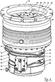
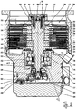
- Vacuum pump 10 shown comprises a housing 16 with a pump inlet 14 surrounded by an inlet flange 12 and in the housing 16 a plurality of pumping stages for delivering a pending at the pump inlet 14 gas to a pump provided on the lower part 90 of the housing 16 pump outlet 74. Between the lower part 90 and the housing 16, a seal 81 is arranged.
- the vacuum pump 10 comprises in the housing 16 or in the lower part 90 a motor stator 92 and a motor rotor 93 with a rotor shaft 20 rotatably mounted about a rotation axis 18.
- the vacuum pump 10 is designed as a turbomolecular pump and comprises a plurality of pump-connected with each other in series turbomolecular pumping stages with a plurality of connected to the rotor shaft 20 turbomolecular rotor disks 22 and a plurality of axially disposed between the rotor disks 22 and fixed in the housing 16 turbomolecular stator disks 24 by spacer rings 26 are held at a desired axial distance from each other.
- the pump-active system realized by means of the turbomolecular pumping stages therefore builds up in regular alternation of rotor disks 22 and stator disks 24.
- the rotor disks 22 and stator disks 24 provide in a scooping region 28 an axial pumping action directed in the direction of the arrow 30.
- the vacuum pump 10 may optionally have subordinate to the turbomolecular pumping stages one or more, known per se Holweck pumping stages, which are not shown.
- three Holweck pumping stages which are arranged one inside the other in the radial direction and pump-connected with one another in series, may be provided.
- the rotor-side part of the Holweck pumping stages may have a rotor hub connected to the rotor shaft 20 and two cylinder shell-shaped Holweck rotor sleeves fastened to the rotor hub and supported by the latter, which are oriented coaxially to the rotor axis 18 and are nested one inside the other in the radial direction.
- Holweck stator sleeves can be provided, which are also oriented coaxially with the axis of rotation 18 and are nested in the radial direction.
- the pump-active surfaces of the Holweck pump stages are each formed by the radial lateral surfaces of a Holweck rotor sleeve and a Holweck stator sleeve opposite one another, forming a narrow radial Holweck gap.
- one of the pump-active surfaces is smooth, in particular that of the Holweck rotor sleeve, and the opposite pump-active surface, in particular the Holweck stator, has a structuring with helically around the rotation axis 18 in the axial direction extending grooves in which through the Rotation of the rotor propelled the gas and thereby pumped.
- the Holweck pump stages are not provided.
- a sealing region 34 is formed by a specially, in this case asymmetrically shaped, stator disk 24 which minimizes the remaining gaps to the rotor disks 22 to provide better sealing against unwanted backflow between the first and second pumping stages.
- a biasing and sealing ring 32 is disposed between the inner wall of the housing 16 and the turbomolecular pumping stages, in particular between two spacer rings 26.
- the biasing and sealing ring 32 ensures that the tolerance-laden stack of spacer rings 26 is securely biased axially between the housing 16 and lower part 90. Furthermore, it additionally seals the gap between the stack of spacer rings 26 and the wall of the housing 16 against undesired backflows from the fore-vacuum / ejection region into the high-vacuum / intake region.
- a flood gas inlet 36 is arranged, via which the vacuum pump 10 can be flooded with flooding gas.
- the tide gas inlet 36 is advantageously pump downstream or below the biasing and sealing ring 32.
- the lying at the height of the connection spacer ring 26 is preferably provided on its lateral surface over the entire circumference with a channel or a recess, so that the tidal gas first throughout Distributed annular channel with good conductance and then as uniformly as possible penetrates the gap or the recesses in the stator stack with a lower conductance over the circumference and reaches the mechanically more stable upstream prevacuum pump stages against flooding.
- a coolant inlet 38 and a coolant outlet 40 are arranged, between which runs a coolant line formed by at least one coolant tube 76, which is guided in turns around the lower part 90.
- a coolant pump can be connected, by means of which cooling liquid can be pumped through the coolant line in order to cool the vacuum pump 10.
- the coolant tube 76 may be in preformed recesses of the lower part 90, for example according to EP 3 070 335 A1 be pressed in.
- the pipe ends can either as a respective pipe section at any angle from the contour of the pump 10th stand out, for example, to be connected with insulation displacement fittings or special connectors at the inlet 38 and outlet 40.
- connection blocks which form the inlet 38 and the outlet 40 and which in turn are fixed to the lower part 90.
- the tight connection of tube 76 and terminal block 38, 40 can be made in various ways, e.g. by soldering, welding, clamping / pressing / stretching or with separate sealing elements, e.g. (cutting) sealing rings or bands or with special connectors with integrated sealing system.
- a coolant line which starting from the inlet 38 has three complete, spirally arranged wraps of the lower part 90 and then ends at the outlet 40.
- any number or portion of wraps may intersect one or more times at different radius and / or at different axial heights of the axis of rotation 18, or may also be reversed one or more times in its direction of rotation, e.g. by means of U-shaped bends or arranged Umlenkblöcken that receive two pipe pieces ends similar to the terminal blocks and establish a connection between them.
- Such connection and diverter blocks may also include a valve that controls the flow of coolant or may interrupt it as needed.
- any block may also have another terminal to which e.g. an additional, in particular parallel, coolant line or one or more valves for a deflection or distribution of the coolant flow as needed in different branches of the coolant pipe system, which can also serve as a bypass or diversion is present or are available.
- the rotatable mounting of the rotor shaft 20 is effected by a rolling bearing 42 in the region of the pump outlet 74 and a permanent magnet bearing 44 in the region of the pump inlet 14.
- the permanent magnet bearing 44 comprises a rotor-side bearing half 46 and a stator bearing half 48, each comprising a ring stack of a plurality of stacked in the axial direction of permanent magnetic rings 50, 52, wherein the magnetic rings 50, 52 facing each other with formation of a radial bearing gap 54.
- an emergency or fishing camp 56 is provided, which is designed as an unlubricated rolling and idle in normal operation of the vacuum pump without touching and passes only at an excessive radial deflection of the rotor relative to the stator into engagement to a radial stop for to form the rotor, which prevents a collision of the rotor-side structures with the stator-side structures.
- the emergency or safety bearing 56 is taken separately via an insert and can therefore be changed independently of the permanent magnet bearing 44.
- the rolling bearing 42 is gripped by a ring holder, which in turn is axially and radially decoupled by elastomeric elements in a rolling bearing support or rolling bearing mount 84 is received, which is securely fixed to the lower part 90.
- Mechanical stops limit the possible relative movements between the ring holder and the roller bearing suspension 84.
- a conical spray screw 58 with an outer diameter which increases towards the rolling bearing 42 is provided on the rotor shaft 20, which can receive operating means, in particular lubricants, supplied by means of a lubricant channel 60 and feed it to the rolling bearing.
- the propeller screw 58 may preferably according to EP 2 740 956 A2 be designed.
- the resource is circulated by a lubricant pump 78.
- the lubricant pump 78 is preferably according to EP 2 060 794 A2 built up. you can supply in particular a lubricant supply channel, the at least in a segment according to EP 2 801 725 A2 constructed as an O-ring sealed round channel.
- the vacuum pump 10 For rotatably driving the rotor shaft 20, the vacuum pump 10 includes an electric drive motor 62 having a motor stator 92 and a motor rotor 93 formed on the rotor shaft 20.
- a control unit 64 controls the drive motor 62. Via an electrical connection 66, the vacuum pump 10 and in particular the control unit 64 and the drive motor 62 can be supplied with electric current.
- the control unit 64 forms the lower region of the housing 16 and is covered by a cover 80.
- one or more seals 77 may be inserted circumferentially between control unit 64, cover 80 and / or lower part 90, or the corresponding transitions with other sealing means, such as liquid sealants, adhesives or especially moldable seals be closed in order to obtain security against the ingress of media and / or impurities.
- the current can be conducted through the cover 80 into the housing and, in particular, supplied to the drive motor 62.
- the vacuum feedthrough 86 can according to EP 1 843 043 A2 be configured, in the example described here, a board different voltage potentials and signals separately from the inside of the pump, ie from the vacuum area, to the outside, ie to the "atmosphere" and in particular to the control unit 64 leads.
- both the control unit 64 or on the part of the drive motor 62 or on the part of the pump-active components on the housing 16 mainly undesirable heat into the pump can be introduced.
- the coolant such as water, advantageously flows from the inlet 38 to the outlet 40 because the control unit 64 is to be kept coolest.
- a cover 88 may be arranged on the radial outer side of the lower part 90.
- the casing 88 which can be designed as a shell-shaped longitudinally to the axis of rotation 18 of the pump 10 slotted sheet metal sleeve, is advantageously not shown in the external view of the pump 10 in order to obtain a better view of the underlying solutions.
- the trim 88 may have one or more viewing windows or cut-outs to accommodate any ports of the base 90, e.g. a barrier gas inlet 68 to perform to the outside or to view the type data (nameplate or engraving) of the pump 10, which are permanently attached to the lower part 90.
- the barrier gas inlet 68 is also referred to as flushing gas connection.
- Purge gas may be introduced via the purge gas inlet 68 to protect the engine 62 in the engine compartment in which the engine 62 is housed.
- the gas introduced via the blocking gas inlet 68 in the region of the engine protects the components located in the lower part 90 from corrosive and / or self-depositing media, which can occur in the pumping system depending on the application.
- a seal 83 is arranged, so that a labyrinth seal 72 as the only remaining passage on the one hand with their low conductance is a barrier against incoming media in the engine and rolling bearing area and on the other hand, an increased saturation of Wälzlager- and engine area with lock - / inert gas ensures.
- the labyrinth seal 72 is provided between an engine compartment 82 upwardly delimiting the engine mount 82 and the lower rotor disk 22.
- the Motor stator 92 of the drive motor 62 is advantageously protected by a potting compound against corrosion.
- the motor stator 92 is potted in the motor support 82 so that the motor stator 92, motor support 82 and motor stator integral stator side of the labyrinth seal 72 can be aligned in one step with the base 90.
- a chamber 70 Radially outside the labyrinth seal 72 and below the turbomolecular pumping stages is the fore-vacuum region in which, in particular, a chamber 70, which runs around the rotational axis 18 in a ring-shaped manner, is formed, which, as in FIG Fig. 2 can be seen, has a substantially rectangular cross-section.
- this cross-sectional shape is only to be regarded as an example, so that a different cross-sectional shape, for example a square or circular cross-section, can also be realized.
- the chamber 70 can also be accommodated at a different location in the housing 16 or in the lower part 90.
- the chamber 70 is where most of the deposits occur, typically in the fore-vacuum region.
- the chamber 70 is thus located between the last pumping stage and the pump outlet 74.
- the chamber 70 opens into the pump outlet 74.
- the chamber 70 therefore forms an ejection area for the gas pumped by the vacuum pump 10 from the inlet 14, which can pass via the pump outlet 74 into a backing pump (not shown) connected thereto.
- the fore-vacuum pump can then further convey the gas, for example into a line for exhaust gas which is under normal pressure.
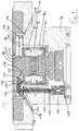
- FIG. 3 a first embodiment of the lower pump part of a vacuum pump according to the invention is shown.
- This lower pump part also comprises a lower part 90, which accommodates a drive motor 62 which has a motor stator 92, which is of annular design and surrounds a motor rotor 93 (not shown here, formed on the rotor shaft 20).
- the motor stator 92 is arranged in a motor support 82, which has a motor stator 92 surrounding the outside, axially extending and hollow cylindrical in the embodiment shown mantle wall 94 and an adjoining the upper end of the shell wall 94 and radially extending end wall 96.
- a through opening 98 is formed for the rotor shaft 20, the diameter of which in the illustrated embodiment coincides with the inner diameter of the motor stator 92.
- a collar portion 100 of the end wall 96 protrudes radially outward beyond the jacket wall 94 and rests on an upper side of the lower part 90.
- the end wall 96 is embedded in a trained as a separate component labyrinth seal member 102 which rests against an upper side of the end wall 96 and the end wall 96 radially outwardly comprising circumferential collar 104 which is bolted to the lower part 90.
- a circumferential extension 106 is provided, which engages for correct alignment and centering of the labyrinth seal member 102 relative to the lower part 90 in a circumferential groove 108 of the lower part 90.
- a through hole 110 for the rotor shaft 20 is formed.
- the passage opening 110 of the labyrinth seal member 102 is aligned with the through opening 98 of the end wall 96 of the motor carrier 82, and also their diameters are at least approximately identical.
- a plurality of concentrically arranged with the passage opening 110 On an upper side of the labyrinth seal element 102, a plurality of concentrically arranged with the passage opening 110, radially spaced circumferential sealing webs 112 are formed, which are part of a labyrinth seal 72.
- connection opening 114 is formed, which is closed vacuum-tight by a arranged on the outside of the jacket wall 94 terminal board 116.
- connection board 116 is screwed to the casing wall 94 and a first sealing ring 118 surrounding the connection opening 114 is arranged between the connection plate 116 and the casing wall 94.
- connection board 116 is used for electrical contacting of the motor stator 92, wherein three outgoing from the motor stator 92 terminal conductor 120 are soldered to the terminal board 116 in the present embodiment.
- connection conductors 120 it would also be conceivable to connect the connection conductors 120 to the connection board 116 in a non-releasable manner in other ways or even to releasably connect them to the connection board 116, for example by means of plug contacts.
- the motor stator 92 is embedded in a potting compound 122 which at least approximately completely fills the interior of the motor support 82 not occupied by the motor stator 92 and thus also surrounds the connection conductors 120 and their connection points on the connection board 116.
- the potting compound 122 is poured into the motor support 82 with the aid of a cylindrical casting core, which protrudes through the passage opening 98 of the end wall 96 of the motor support 82 and the motor stator 92 during the casting process and whose diameter corresponds to the inside diameter of the motor stator 92 and the diameter of the passage opening 98 is adjusted.
- the potting compound 122, the motor stator 82 and the passage opening 98 of the motor support 82 thus define a channel for the rotor shaft 20, in which in operation of the Vacuum pump vacuum prevails and which is accordingly part of a vacuum space 124.
- connection board 116 forms a, here radial, vacuum feedthrough between the vacuum space 124 and the pressure space 126.
- the motor control board 128 is electrically connected to the terminal board 116 by means of three supply conductors 130, which extend through the pressure chamber 126.
- the connection of the supply conductor 130 to the terminal board 116 and the motor control board 128 can each be carried out insoluble.
- at least one connector 132 is provided, which allows a simple solution of the supply conductor 130 of the terminal board 116 and of the motor control board 128.
- comparatively shorter first supply conductor sections are soldered to the motor control board 128 and provided with a first plug contact and soldered comparatively longer second supply conductor sections to the terminal board 116 and provided with a complementary second plug contact.
- a second sealing ring 134 extends around the motor support 82 between a shoulder of the shell wall 94 of the motor support 82 and a complementary
- a third seal ring 136 extends radially outwardly of the pressure chamber 126 along the outer periphery of the end wall 96 between the collar portion 100 and the base 90.
- a fourth seal ring 138 extends parallel there between the collar portion 100 and the labyrinth seal member 102 Preventing penetration of process gases in the area of the motor rotor 93.
- a fifth sealing ring 140 enclosing the through-openings 98, 110 is shown between the end wall 96 and the labyrinth seal element 102, which however is redundant in this embodiment.
- a second embodiment of the lower pump part of a vacuum pump according to the invention is shown.
- This lower part of the pump differs from the one in Fig. 3 shown pump part substantially only in that the connection opening 114 and the connection board 116 are not arranged here on the jacket wall 94 of the motor carrier 82, but on the end wall 96 of the motor carrier 82.
- the connection board 116 thus forms an axial vacuum feedthrough here.
- the labyrinth seal member 102 forms on its motor support 82 facing bottom of a recess 142 which receives the terminal board 116 and which via a bore 144 in the collar portion 100 with the Pressure chamber 126 communicates.
- atmospheric pressure also prevails during operation of the vacuum pump, and all five sealing rings 118, 134, 136, 138 and 140 assume a sealing function between the pressure chamber 126 and the vacuum space 124.
Landscapes
- Engineering & Computer Science (AREA)
- Mechanical Engineering (AREA)
- General Engineering & Computer Science (AREA)
- Non-Positive Displacement Air Blowers (AREA)
- Connection Of Motors, Electrical Generators, Mechanical Devices, And The Like (AREA)
Abstract
Description
- Die vorliegende Erfindung betrifft eine Vakuumpumpe, insbesondere Turbomolekularpumpe, umfassend einen Vakuumraum, einen in dem Vakuumraum angeordneten Motorrotor und einen den Motorrotor umgebenden Motorstator.
- Eine derartige Vakuumpumpe ist grundsätzlich bekannt. Zur Versorgung des Motorstators mit elektrischer Energie sind drei Versorgungsleiter vorgesehen, einer für jede Phase, welche den Motorstator mit einer Motorsteuerungsplatine verbinden. Da die Versorgungsleiter in einem Bereich der Vakuumpumpe verlaufen, in welchem im Betrieb der Vakuumpumpe Vakuum herrscht, müssen die Versorgungsleiter an die Motorsteuerungsplatine angelötet werden und die Lötstellen auf der Motorsteuerungsplatine in einer dielektrischen Vergussmasse vergossen werden, damit es unter gewissen Gasatmosphären, insbesondere unter Argon, nicht zu elektrischen Überschlägen kommt.
- Das Vergießen der Lötstellen auf der Motorsteuerungsplatine ist insofern nachteilig, als das Aushärten der Vergussmasse zeitaufwendig ist. So kann das Aushärten je nach Art der verwendeten Vergussmasse bis zu zwei Tagen benötigen. Stellt sich bei einem anschließenden Test heraus, dass der Verguss nicht dicht ist, so müssen die Versorgungsleiter durchtrennt und die Motorsteuerungsplatine entsorgt werden. Dies ist kosten- und zeitintensiv, da eine neue Motorsteuerungsplatine benötigt wird und der Verguss erneut zwei Tage in Anspruch nimmt.
- Eine Aufgabe der Erfindung besteht darin, eine Vakuumpumpe der eingangs genannten Art zu schaffen, welche sich durch eine wirtschaftlichere Herstellung auszeichnet.
- Zur Lösung der Aufgabe ist eine Vakuumpumpe mit den Merkmalen des Anspruchs 1 vorgesehen.
- Die erfindungsgemäße Vakuumpumpe umfasst insbesondere einen den Motorstator beherbergenden Motorträger, dessen Außenseite teilweise an einen Druckraum angrenzt, der eine dem Druckraum zugewandte Anschlussöffnung aufweist, welche mittels einer Anschlussplatine vakuumdicht verschlossen ist, und der eine den Motorstator teilweise einschließende Vergussmasse enthält, wenigstens einen elektrischen Anschlussleiter, der sich durch die Vergussmasse hindurch erstreckt, dessen eines Ende an den Motorstator angeschlossen ist und dessen anderes Ende an eine der Vergussmasse zugewandte Seite der Platine angeschlossen ist, und wenigstens einen elektrischen Versorgungsleiter, der durch den Druckraum verläuft und dessen eines Ende an eine dem Druckraum zugewandte Seite der Platine angeschlossen ist.
- Der Erfindung liegt der allgemeine Gedanke zugrunde, den Motorstator nicht mittels einer durchgehenden Versorgungsleitung direkt an die Motorsteuerung anzuschließen, sondern indirekt, nämlich über die Anschlussleiter, die Anschlussplatine und die Versorgungsleiter. Dies hat den Vorteil, dass der Motorstator nach dem Anschließen an die Anschlussplatine und Vergießen in dem Motorträger getestet werden kann, bevor er in die Vakuumpumpe eingebaut wird. Sollte sich der Verguss in diesem Vormontagezustand als undicht erweisen und es zu elektrischen Überschlägen kommen, so kann diese fehlerhafte Baugruppe auf einfache Weise durch eine fehlerfreie Baugruppe ersetzt werden, ohne dass sich der Zusammenbau der Vakuumpumpe insgesamt verzögert.
- Da die Anschlussplatine als eine Vakuumdurchführung wirkt, können des Weiteren die Versorgungsleiter durch den Druckraum verlaufen, in welchem beispielsweise Atmosphärendruck herrschen kann, wodurch es möglich ist, die Versorgungsleiter ohne die Gefahr von elektrischen Überschlägen lösbar an eine Motorsteuerung, insbesondere eine Motorsteuerungsplatine, anzubinden. Die Motorsteuerungsplatine lässt sich also auf einfache Weise mit dem Motorstator verbinden und braucht auch nicht entsorgt zu werden, wenn die den Motorträger und den darin vergossenen Motorstator umfassende Baugruppe ausgetauscht werden und/oder der Motorstator neu vergossen werden muss, was letztlich zu einer erhöhten Flexibilität beim Zusammenbau der Vakuumpumpe und zu einer wirtschaftlicheren Herstellung der Vakuumpumpe beiträgt.
- Vorteilhafte Ausbildungen der Erfindung sind den Unteransprüchen, der Beschreibung und der Zeichnung zu entnehmen.
- Gemäß einer Ausführungsform sind bzw. ist der wenigstens eine Anschlussleiter und/oder der wenigstens eine Versorgungsleiter unlösbar an die Anschlussplatine angeschlossen, insbesondere an die Anschlussplatine angelötet. Alternativ können bzw. kann der wenigstens eine Anschlussleiter und/oder der wenigstens eine Versorgungsleiter aber auch lösbar an die Anschlussplatine angeschlossen sein, insbesondere mittels einer Steckverbindung.
- Vorteilhafterweise ist das andere Ende des wenigstens einen elektrischen Versorgungsleiters mit einer Motorsteuerung, insbesondere mit einer Motorsteuerungsplatine, verbunden. Beispielsweise kann das andere Ende des wenigstens einen elektrischen Versorgungsleiters unlösbar an die Motorsteuerungsplatine angeschlossen sein, insbesondere angelötet sein. Alternativ kann das andere Ende des wenigstens einen elektrischen Versorgungsleiters aber auch lösbar an die Motorsteuerungsplatine angeschlossen sein, insbesondere mittels einer Steckverbindung.
- Gemäß einer weiteren Ausführungsform ist die Anschlussplatine an der Außenseite des Motorträgers angebracht. Dabei kann die Anschlussplatine an einem sich axial erstreckenden Wandabschnitt des Motorträgers oder an einem sich radial erstreckenden Wandabschnitt des Motorträgers angebracht sein. In diesem Kontext ist die Orientierung "axial" durch die Drehachse des Motorrotors definiert. Die Orientierung "radial" ist entsprechend rechtwinklig zur Drehachse des Motorrotors ausgerichtet.
- Für eine besonders einfache Montage kann die Anschlussplatine an den Wandabschnitt angeschraubt sein.
- Vorzugsweise ist ein Dichtungselement zwischen der Anschlussplatine und dem Wandabschnitt angeordnet, insbesondere welches die Anschlussöffnung vollständig umschließt. Dies trägt zu einer besonders zuverlässigen Trennung des Vakuumraums von dem Druckraum bei.
- Gemäß einer weiteren Ausführungsform umfasst der Motorträger eine sich axial erstreckende, insbesondere hohlzylindrische, Mantelwand und eine sich radial erstreckende Stirnwand, in welcher eine Durchgangsöffnung ausgebildet ist, die Teil des Vakuumraums ist.
- Für einen Schutz des Motorstators vor Korrosion und unerwünschten elektrischen Überschlägen ist der Motorstator mit Ausnahme einer den Vakuumraum begrenzenden Innenseite idealerweise vollständig von der Vergussmasse umgeben.
- Bevorzugt ist ein durch den Motorstator und Wände des Motorträgers definierter Zwischenraum vollständig mit der Vergussmasse ausgefüllt. Dies ermöglicht eine besonders einfache Herstellung der den Motorträger und den Motorstator umfassenden Baugruppe, da der Motorträger nach dem Einsetzen des Motorstators lediglich mit der Vergussmasse aufgefüllt werden muss.
- Zu einer noch höheren Flexibilität beim Zusammenbau der Vakuumpumpe trägt außerdem bei, wenn der Motorträger und ein dem Motorträger zugeordnetes Labyrinthdichtungselement als separate Bauteile ausgebildet sind. Insbesondere ermöglicht dies eine von dem Motorträger unabhängige und somit exaktere Ausrichtung des Labyrinthdichtungselements innerhalb der Vakuumpumpe.
- Dabei kann der Motorträger, insbesondere eine Stirnwand des Motorträgers, in das Labyrinthdichtungselement eingesetzt sein.
- Gemäß einer weiteren Ausführungsform ist eine Aussparung in dem Labyrinthdichtungselement ausgebildet, welche mit dem Druckraum kommuniziert. Diese Aussparung kann durch die Anschlussplatine begrenzt sein, insbesondere wenn die Anschlussplatine an der Stirnwand des Motorträgers angebracht ist. Hierdurch ist es möglich, die Versorgungsleiter gewissermaßen axial an die Anschlussplatine anzuschließen.
- Zur besseren Trennung des Vakuumraums von dem Druckraum trägt bei, wenn wenigstens ein um den Vakuumraum herumlaufendes Dichtungselement im Bereich der Aussparung zwischen dem Labyrinthdichtungselement und dem Motorträger angeordnet ist.
- Aus dem gleichen Grund ist vorteilhafterweise auch wenigstens ein um den Vakuumraum herumlaufendes Dichtungselement zwischen dem Motorträger und einem Unterteil der Vakuumpumpe angeordnet.
- Die Erfindung wird nachfolgend lediglich beispielhaft anhand der schematischen Zeichnung erläutert.
- Fig. 1
- zeigt eine perspektivische Ansicht einer Vakuumpumpe gemäß dem Stand der Technik.
- Fig. 2
- zeigt eine Schnittansicht der Vakuumpumpe von
Fig. 1 . - Fig. 3
- zeigt eine Schnittansicht eines unteren Teils einer ersten Ausführungsform einer erfindungsgemäßen Vakuumpumpe.
- Fig. 4
- zeigt eine Schnittansicht eines unteren Teils einer zweiten Ausführungsform einer erfindungsgemäßen Vakuumpumpe.
- Die in
Fig. 1 und2 gezeigte Vakuumpumpe 10 umfasst ein Gehäuse 16 mit einem von einem Einlassflansch 12 umgebenen Pumpeneinlass 14 sowie im Gehäuse 16 mehrere Pumpstufen zur Förderung eines an dem Pumpeneinlass 14 anstehenden Gases zu einem am Unterteil 90 des Gehäuses 16 vorgesehenen Pumpenauslass 74. Zwischen dem Unterteil 90 und dem Gehäuse 16 ist eine Dichtung 81 angeordnet. Die Vakuumpumpe 10 umfasst im Gehäuse 16 bzw. im Unterteil 90 einen Motorstator 92 und einen Motorrotor 93 mit einer um eine Rotationsachse 18 drehbar gelagerten Rotorwelle 20. - Die Vakuumpumpe 10 ist als Turbomolekularpumpe ausgebildet und umfasst mehrere pumpwirksam miteinander in Serie geschaltete turbomolekulare Pumpstufen mit mehreren mit der Rotorwelle 20 verbundenen turbomolekularen Rotorscheiben 22 und mehreren in axialer Richtung zwischen den Rotorscheiben 22 angeordneten und in dem Gehäuse 16 festgelegten turbomolekularen Statorscheiben 24, die durch Distanzringe 26 in einem gewünschten axialen Abstand zueinander gehalten sind. Das mittels der turbomolekularen Pumpstufen realisierte pumpaktive System baut sich daher im regelmäßigen Wechsel von Rotorscheiben 22 und Statorscheiben 24 auf. Dabei sind nur einige der gezeigten Bestandteile der Lesbarkeit wegen mit Nummern kenntlich gemacht. Die Rotorscheiben 22 und Statorscheiben 24 stellen in einem Schöpfbereich 28 eine in Richtung des Pfeils 30 gerichtete axiale Pumpwirkung bereit.
- Die Vakuumpumpe 10 kann optional nachgeordnet zu den turbomolekularen Pumpstufen eine oder mehrere, an sich bekannte Holweck-Pumpstufen aufweisen, die nicht dargestellt sind. Beispielsweise können drei in radialer Richtung ineinander angeordnete und pumpwirksam miteinander in Serie geschaltete Holweck-Pumpstufen vorgesehen sein. Der rotorseitige Teil der Holweck-Pumpstufen kann dabei eine mit der Rotorwelle 20 verbundene Rotornabe und zwei an der Rotornabe befestigte und von dieser getragene zylindermantelförmige Holweck-Rotorhülsen aufweisen, die koaxial zu der Rotorachse 18 orientiert und in radialer Richtung ineinander geschachtelt sind. Ferner können ein, zwei oder drei zylindermantelförmige Holweck-Statorhülsen vorgesehen sein, die ebenfalls koaxial zu der Rotationsachse 18 orientiert und in radialer Richtung ineinander geschachtelt sind. Die pumpaktiven Oberflächen der Holweck-Pumpstufen sind jeweils durch die einander unter Ausbildung eines engen radialen Holweck-Spalts gegenüberliegenden, radialen Mantelflächen jeweils einer Holweck-Rotorhülse und einer Holweck-Statorhülse gebildet. Dabei ist jeweils eine der pumpaktiven Oberflächen glatt ausgebildet, insbesondere die der Holweck-Rotorhülse, und die gegenüberliegende pumpaktive Oberfläche, insbesondere der Holweck-Statorhülse, weist eine Strukturierung mit schraubenlinienförmig um die Rotationsachse 18 herum in axialer Richtung verlaufenden Nuten auf, in denen durch die Rotation des Rotors das Gas vorangetrieben und dadurch gepumpt wird. Bei der dargestellten Vakuumpumpe 10 sind die Holweck-Pumpstufen allerdings nicht vorgesehen.
- Ein Abdichtungsbereich 34 wird durch eine speziell, in diesem Fall asymmetrisch ausgeformte Statorscheibe 24 gebildet, die die verbleibenden Zwischenräume zu den Rotorscheiben 22 minimal hält, um eine bessere Dichtigkeit gegen ungewollte Rückströmungen zwischen der ersten und zweiten Pumpstufe zu erzielen.
- Ein Vorspann- und Dichtring 32 ist zwischen der Innenwand des Gehäuses 16 und den turbomolekularen Pumpstufen, insbesondere zwischen zwei Distanzringen 26, angeordnet. Der Vorspann- und Dichtring 32 sorgt dafür, dass der toleranzbehaftete Stapel aus Distanzringen 26 sicher axial zwischen Gehäuse 16 und Unterteil 90 vorgespannt wird. Weiterhin dichtet er zusätzlich den Spalt zwischen dem Stapel von Distanzringen 26 und der Wandung des Gehäuses 16 gegen ungewollte Rückströmungen aus dem Vorvakuum-/Ausstossbereich in den Hochvakuum-/Ansaugbereich ab.
- Am Gehäuse 16 ist ein Flutgaseinlass 36 angeordnet, über den die Vakuumpumpe 10 mit Flutgas geflutet werden kann. Der Flutgaseinlass 36 liegt vorteilhaft pumpstromabwärts bzw. unterhalb des Vorspann- und Dichtrings 32. Der auf Höhe des Anschlusses liegende Distanzring 26 ist vorzugsweise auf seiner Mantelfläche über den gesamten Umfang mit einem Kanal bzw. einer Aussparung versehen, so dass sich das Flutgas zuerst im gesamten Ringkanal mit gutem Leitwert verteilt und dann über den Umfang möglichst gleichmäßig den Spalt bzw. die Ausnehmungen im Statorstapel mit geringerem Leitwert durchdringt und die gegen Fluten mechanisch stabileren Vorvakuum-nahen Pumpstufen erreicht.
- Am Unterteil 90 sind ein Kühlmitteleinlass 38 und ein Kühlmittelauslass 40 angeordnet, zwischen denen eine von wenigstens einem Kühlmittelrohr 76 gebildete Kühlmittelleitung verläuft, die in Windungen um das Unterteil 90 herum geführt ist. An den Kühlmitteleinlass 38 und den Kühlmittelauslass 40 kann eine Kühlmittelpumpe angeschlossen werden, mittels der Kühlflüssigkeit durch die Kühlmittelleitung gepumpt werden kann, um die Vakuumpumpe 10 zu kühlen.
- Das Kühlmittelrohr 76 kann in vorgeformte Ausnehmungen des Unterteils 90, z.B. gemäß
EP 3 070 335 A1 , eingepresst sein. Die Rohrenden können entweder als jeweiliger Rohrabschnitt in einem beliebigen Winkel aus der Kontur der Pumpe 10 herausstehen, um z.B. mit Schneid-Klemm-Verschraubungen oder speziellen Steckverbindern am Einlass 38 bzw. Auslass 40 angeschlossen zu werden. - Die Rohrenden können auch in den Anschlussblöcken, die den Einlass 38 bzw. den Auslass 40 bilden und ihrerseits an dem Unterteil 90 fixiert sind, aufgenommen werden. Dabei kann die dichte Verbindung von Rohr 76 und Anschlussblock 38, 40 auf verschiedene Arten hergestellt werden, z.B. durch Löten, Schweißen, Klemmen/Pressen/Dehnen oder mit separaten Dichtelementen, z.B. (schneidenden) Dichtringen oder -bändern oder auch mit speziellen Steckverbindern mit integriertem Dichtsystem.
- Dargestellt ist eine Kühlmittelleitung, die beginnend vom Einlass 38 drei vollständige, spiralförmig angeordnete Umschlingungen des Unterteils 90 aufweist und dann am Auslass 40 endet. Alternativ können beliebige Anzahlen oder Teile von Umschlingungen sich ein- oder mehrmals auf verschiedenem Radius und/oder auf unterschiedlichen axialen Höhen der Rotationsachse 18 kreuzen oder auch in ihrer Umlaufrichtung ein- oder mehrmals umkehren, z.B. mittels U-förmigen Biegungen oder angeordneten Umlenkblöcken, die zwei Rohrstückenden ähnlich den Anschlussblöcken aufnehmen und eine Verbindung zwischen ihnen herstellen. Solche Anschluss- und Umlenkblöcke können auch ein Ventil enthalten, das den Kühlmittelfluss regelt oder bei Bedarf unterbrechen kann. Alternativ kann ein beliebiger Block auch einen weiteren Anschluss aufweisen, an dem z.B. ein zusätzlicher, insbesondere paralleler, Kühlmittelstrang bzw. ein oder mehrere Ventile für eine Umlenkung bzw. Verteilung des Kühlmittelstroms je nach Bedarfsfall in verschiedene Zweige des Kühlmittelrohrsystems, die auch als Bypass bzw. Umleitung dienen können, vorhanden ist bzw. vorhanden sind.
- Die drehbare Lagerung der Rotorwelle 20 wird durch ein Wälzlager 42 im Bereich des Pumpenauslasses 74 und ein Permanentmagnetlager 44 im Bereich des Pumpeneinlasses 14 bewirkt.
- Das Permanentmagnetlager 44 umfasst eine rotorseitige Lagerhälfte 46 und eine statorseitige Lagerhälfte 48, die jeweils einen Ringstapel aus mehreren in axialer Richtung aufeinandergestapelten permanentmagnetischen Ringen 50, 52 umfassen, wobei die Magnetringe 50, 52 unter Ausbildung eines radialen Lagerspalts 54 einander gegenüberliegen.
- Innerhalb des Permanentmagnetlagers 44 ist ein Not- oder Fanglager 56 vorgesehen, das als ungeschmiertes Wälzlager ausgebildet ist und im normalen Betrieb der Vakuumpumpe ohne Berührung leer läuft und erst bei einer übermäßigen radialen Auslenkung des Rotors gegenüber dem Stator in Eingriff gelangt, um einen radialen Anschlag für den Rotor zu bilden, der eine Kollision der rotorseitigen Strukturen mit den statorseitigen Strukturen verhindert. Das Not- oder Fanglager 56 wird über einen Einsatz separat gefasst und kann daher unabhängig vom Permanentmagnetlager 44 gewechselt werden.
- Das Wälzlager 42 wird durch einen Ringhalter gefasst, der seinerseits durch elastomere Elemente sowohl axial als auch radial entkoppelt in einer Wälzlagerhalterung bzw. Wälzlageraufhängung 84 aufgenommen wird, die am Unterteil 90 sicher fixiert ist. Mechanische Anschläge begrenzen die möglichen Relativbewegungen zwischen Ringhalter und Wälzlageraufhängung 84.
- Im Bereich des Wälzlagers 42 ist an der Rotorwelle 20 eine konische Spritzschraube 58 mit einem zu dem Wälzlager 42 hin zunehmenden Außendurchmesser vorgesehen, die mittels eines Schmiermittelkanals 60 zugeführtes Betriebsmittel, insbesondere Schmiermittel, aufnehmen und dem Wälzlager zuführen kann. Die Spritzschraube 58 kann bevorzugt gemäß
EP 2 740 956 A2 ausgestaltet sein. - Das Betriebsmittel wird von einer Schmiermittelpumpe 78 umgewälzt. Die Schmiermittelpumpe 78 ist bevorzugt gemäß
EP 2 060 794 A2 aufgebaut. Sie kann dabei insbesondere einen Schmiermittelvorlaufkanal versorgen, der zumindest in einem Segment gemäßEP 2 801 725 A2 als O-Ring gedichteter Rundkanal aufgebaut ist. - Durch die Schmiermittelpumpe 78 lässt sich eine aktive, geregelte Betriebsmittelversorgung realisieren.
- Zum drehenden Antreiben der Rotorwelle 20 umfasst die Vakuumpumpe 10 einen elektrischen Antriebsmotor 62 mit einem Motorstator 92 und einem an der Rotorwelle 20 ausgebildeten Motorrotor 93. Eine Steuereinheit 64 steuert den Antriebsmotor 62 an. Über einen elektrischen Anschluss 66 können die Vakuumpumpe 10 und insbesondere die Steuereinheit 64 sowie der Antriebsmotor 62 mit elektrischem Strom versorgt werden. Die Steuereinheit 64 bildet den unteren Bereich des Gehäuses 16 und ist durch einen Deckel 80 abgedeckt. Die Steuereinheit 64 und der Deckel 80 verschließen das Unterteil 90. Je nach Ausführung können zwischen Steuereinheit 64, Deckel 80 und/oder Unterteil 90 eine oder mehrere Dichtungen 77 umlaufend eingelegt oder mit anderen Dichtmitteln, etwa Flüssigdichtmitteln, Klebstoffen oder insbesondere applizierbaren Formdichtungen die entsprechenden Übergänge verschlossen werden, um Sicherheit gegen das Eindringen von Medien und/oder Verunreinigungen zu erlangen. Mittels wenigstens einer elektrischen Durchführung 86 kann der Strom durch den Deckel 80 hindurch in das Gehäuse geführt und insbesondere dem Antriebsmotor 62 zugeführt werden.
- Die Vakuumdurchführung 86 kann gemäß
EP 1 843 043 A2 ausgestaltet sein, wobei bei dem hier beschriebenen Beispiel eine Platine verschiedene Spannungspotentiale und Signale separat voneinander aus dem Pumpeninneren, also aus dem Vakuumbereich, nach außen, also zur "Atmosphäre" und insbesondere zur Steuereinheit 64 führt. - Je nach Anwendungsfall kann sowohl seitens der Steuereinheit 64 oder auch seitens des Antriebsmotors 62 oder seitens der pumpaktiven Bestandteile über das Gehäuse 16 hauptsächlich unerwünscht Wärme in die Pumpe eingebracht werden. Das Kühlmittel, etwa Wasser, fließt vorteilhaft vom Einlass 38 zum Auslass 40, da die Steuereinheit 64 am kühlsten gehalten werden soll.
- An der radialen Außenseite des Unterteils 90 kann eine Verkleidung 88 angeordnet sein. Die Verkleidung 88, die mantelförmig als längs zur Rotationsachse 18 der Pumpe 10 geschlitzte Blechhülse ausgeführt sein kann, ist in der Außenansicht der Pumpe 10 vorteilhaft nicht dargestellt, um eine bessere Sicht auf die darunter liegenden Lösungen zu erlangen. Die Verkleidung 88 kann ein oder mehrere Sichtfenster bzw. Ausschnitte aufweisen, um beliebige Anschlüsse des Unterteils 90, z.B. einen Sperrgaseinlass 68, nach außen durchzuführen oder um den Blick auf die Typendaten (Typschild oder Gravur) der Pumpe 10 freizugeben, welche unlösbar am Unterteil 90 angebracht sind.
- Der Sperrgaseinlass 68 wird auch als Spülgasanschluss bezeichnet. Über den Sperrgaseinlass 68 kann Spülgas zum Schutz des Motors 62 in den Motorraum, in welchem der Motor 62 untergebracht ist, eingebracht werden. Das über den Sperrgaseinlass 68 im Bereich des Motors eingelassene Gas schützt die im Unterteil 90 befindlichen Bestandteile vor korrosiven und/oder sich ablagernden Medien, die je nach Anwendungsfall im Pumpsystem anfallen können. Zwischen Motorträger 82 und Unterteil 90 ist eine Dichtung 83 angeordnet, so dass eine Labyrinthdichtung 72 als einziger verbliebener Durchlass einerseits mit ihrem geringen Leitwert eine Sperre gegen einströmende Medien in den Motor- und Wälzlagerbereich darstellt und andererseits eine erhöhte Sättigung des Wälzlager- und Motorbereichs mit Sperr-/Inertgas sichert.
- Die Labyrinthdichtung 72 ist zwischen einem den Motorraum nach oben hin begrenzenden Motorträger 82 und der unteren Rotorscheibe 22 vorgesehen. Der Motorstator 92 des Antriebsmotors 62 ist vorteilhaft durch eine Vergussmasse gegen Korrosion geschützt. Bei der dargestellten Ausführung ist der Motorstator 92 in dem Motorträger 82 vergossen, so dass die Einheit aus Motorstator 92, Motorträger 82 und der mit dem Motorträger einteilig ausgeführten Statorseite der Labyrinthdichtung 72 in einem Schritt mit dem Unterteil 90 ausgerichtet bzw. zentriert verbunden werden kann.
- Radial außerhalb der Labyrinthdichtung 72 und unterhalb der turbomolekularen Pumpstufen befindet sich der Vorvakuumbereich, in welchem insbesondere eine ringförmig um die Rotationsachse 18 umlaufende Kammer 70 ausgebildet ist, die, wie in
Fig. 2 zu sehen ist, einen im Wesentlichen rechteckigen Querschnitt aufweist. Diese Querschnittsform ist allerdings nur als Beispiel zu sehen, so dass auch eine andere Querschnittsform, z.B. ein quadratischer oder kreisförmiger Querschnitt, realisiert sein kann. Die Kammer 70 kann auch an einer anderen Stelle im Gehäuse 16 bzw. im Unterteil 90 untergebracht sein. Vorzugsweise liegt die Kammer 70 dort, wo die meisten Ablagerungen anfallen, also typischerweise im Vorvakuumbereich. Besonders bevorzugt liegt die Kammer 70 somit zwischen der letzten Pumpstufe und dem Pumpenauslass 74. - Bei der dargestellten Variante mündet die Kammer 70 in den Pumpenauslass 74. Die Kammer 70 bildet daher einen Ausstoßbereich für das durch die Vakuumpumpe 10 vom Einlass 14 her geförderte Gas, welches über den Pumpenauslass 74 in eine daran angeschlossene Vorvakuumpumpe (nicht gezeigt) gelangen kann. Die Vorvakuumpumpe kann das Gas dann weiter, zum Beispiel in eine Leitung für Abgas, die unter Normaldruck steht, fördern.
- Nachfolgend wird der Aufbau einer erfindungsgemäßen Vakuumpumpe beschrieben, welche sich von der in
Fig. 1 und2 gezeigten Vakuumpumpe im Wesentlichen nur in der Ausbildung des unteren Pumpenteils unterscheidet. - In
Fig. 3 ist eine erste Ausführungsform des unteren Pumpenteils einer erfindungsgemäßen Vakuumpumpe dargestellt. Auch dieser untere Pumpenteil umfasst ein Unterteil 90, welches einen Antriebsmotor 62 beherbergt, der einen Motorstator 92 aufweist, welcher ringförmig ausgebildet ist und einen hier nicht gezeigten, an der Rotorwelle 20 ausgebildeten Motorrotor 93 umgibt. Der Motorstator 92 ist in einem Motorträger 82 angeordnet, welcher eine den Motorstator 92 außen umgebende, sich axial erstreckende und im gezeigten Ausführungsbeispiel hohlzylindrisch ausgebildete Mantelwand 94 und eine an das obere Ende der Mantelwand 94 anschließende und sich radial erstreckende Stirnwand 96 aufweist. In der Stirnwand 96 ist eine Durchgangsöffnung 98 für die Rotorwelle 20 ausgebildet, deren Durchmesser im gezeigten Ausführungsbeispiel mit dem Innendurchmesser des Motorstators 92 übereinstimmt. - Ein Kragenabschnitt 100 der Stirnwand 96 ragt radial nach außen über die Mantelwand 94 hervor und liegt auf einer Oberseite des Unterteils 90 auf. Außerdem ist die Stirnwand 96 in ein als separates Bauteil ausgebildetes Labyrinthdichtungselement 102 eingebettet, welches an einer Oberseite der Stirnwand 96 anliegt und einen die Stirnwand 96 radial außen umfassenden umlaufenden Kragen 104 aufweist, welcher mit dem Unterteil 90 verschraubt ist. An einer dem Unterteil 90 zugewandten Unterseite des Kragens 104 ist ein umlaufender Fortsatz 106 vorgesehen, welcher für eine korrekte Ausrichtung und Zentrierung des Labyrinthdichtungselements 102 relativ zum Unterteil 90 in eine umlaufende Nut 108 des Unterteils 90 eingreift.
- Auch in dem Labyrinthdichtungselement 102 ist eine Durchgangsöffnung 110 für die Rotorwelle 20 ausgebildet. Die Durchgangsöffnung 110 des Labyrinthdichtungselements 102 ist mit der Durchgangsöffnung 98 der Stirnwand 96 des Motorträgers 82 ausgerichtet, und auch ihre Durchmesser sind zumindest annähernd identisch.
- An einer Oberseite des Labyrinthdichtungselements 102 sind mehrere konzentrisch mit der Durchgangsöffnung 110 angeordnete, radial beabstandete umlaufende Dichtungsstege 112 ausgebildet, welche Teil einer Labyrinthdichtung 72 sind.
- In der Mantelwand 94 des Motorträgers 82 ist eine Anschlussöffnung 114 ausgebildet, welche durch eine an der Außenseite der Mantelwand 94 angeordnete Anschlussplatine 116 vakuumdicht verschlossen ist. Hierfür ist die Anschlussplatine 116 mit der Mantelwand 94 verschraubt und ein die Anschlussöffnung 114 umschließender erster Dichtungsring 118 zwischen der Anschlussplatine 116 und der Mantelwand 94 angeordnet.
- Die Anschlussplatine 116 dient der elektrischen Kontaktierung des Motorstators 92, wobei drei von der Motorstator 92 abgehende Anschlussleiter 120 im vorliegenden Ausführungsbeispiel an die Anschlussplatine 116 angelötet sind. Grundsätzlich wäre es aber auch denkbar die Anschlussleiter 120 auf andere Weise unlösbar an die Anschlussplatine 116 anzuschließen oder sogar lösbar mit der Anschlussplatine 116 zu verbinden, beispielsweise mithilfe von Steckkontakten.
- Der Motorstator 92 ist in eine Vergussmasse 122 eingebettet, welche den nicht durch den Motorstator 92 eingenommenen Innenraum des Motorträgers 82 zumindest annähernd vollständig ausfüllt und somit auch die Anschlussleiter 120 und deren Anschlusspunkte an der Anschlussplatine 116 umgibt. Das Eingießen der Vergussmasse 122 in den Motorträger 82 erfolgt unter Zuhilfenahme eines zylindrischen Gusskerns, der während des Gießvorgangs durch die Durchgangsöffnung 98 der Stirnwand 96 des Motorträgers 82 und den Motorstator 92 hindurchragt und dessen Durchmesser an den Innendurchmesser des Motorstators 92 und den Durchmesser der Durchgangsöffnung 98 angepasst ist. Im Ergebnis begrenzen die Vergussmasse 122, der Motorstator 82 und die Durchgangsöffnung 98 des Motorträgers 82 also einen Kanal für die Rotorwelle 20, in welchem im Betrieb der Vakuumpumpe Vakuum herrscht und welcher dementsprechend Teil eines Vakuumsraums 124 ist.
- Die dem Motorträger 82 abgewandte Außenseite der Anschlussplatine 116 begrenzt einen sich axial durch das Unterteil 90 hindurch erstreckenden Druckraum 126, in welchem im Betrieb der Vakuumpumpe Atmosphärendruck herrscht. Die Anschlussplatine 116 bildet mit anderen Worten also eine, hier radiale, Vakuumdurchführung zwischen dem Vakuumraum 124 und dem Druckraum 126.
- An der Oberseite des Unterteils 90 ist der Druckraum 126 durch den Kragenabschnitt 100 der Stirnwand 96 des Motorträgers 82 begrenzt. An einer Unterseite des Unterteils 90 ist der Druckraum 126 durch eine Motorsteuerungsplatine 128 begrenzt, welche beispielsweise an das Unterteil 90 angeschraubt sein kann. Die Motorsteuerungsplatine 128 ist elektrisch mit der Anschlussplatine 116 verbunden und zwar mittels dreier Versorgungsleiter 130, die sich durch den Druckraum 126 erstrecken. Die Anbindung der Versorgungsleiter 130 an die Anschlussplatine 116 bzw. die Motorsteuerungsplatine 128 kann jeweils unlösbar erfolgen. Bevorzugt ist aber wenigstens eine Steckverbindung 132 vorgesehen, welche eine einfache Lösung der Versorgungsleiter 130 von der Anschlussplatine 116 bzw. von der Motorsteuerungsplatine 128 ermöglicht. Im vorliegenden Ausführungsbeispiel sind vergleichsweise kürzere erste Versorgungsleiterabschnitte an die Motorsteuerungsplatine 128 angelötet und mit einem ersten Steckkontakt versehen und vergleichsweise längere zweite Versorgungsleiterabschnitte an die Anschlussplatine 116 angelötet und mit einem komplementären zweiten Steckkontakt versehen.
- Zur besseren Abdichtung des Vakuumraums 124 gegenüber dem Druckraum 126 sind zusätzlich zu dem die Anschlussöffnung 114 des Motorträgers 82 umschließenden ersten Dichtungsring 118 noch weitere Dichtungsringe vorgesehen. So verläuft ein zweiter Dichtungsring 134 um den Motorträger 82 herum zwischen einer Schulter der Mantelwand 94 des Motorträgers 82 und einer komplementär ausgebildeten Schulter des Unterteils 90. Ein dritter Dichtungsring 136 verläuft radial außerhalb des Druckraums 126 entlang des äußeren Umfangs der Stirnwand 96 zwischen dem Kragenabschnitt 100 und dem Unterteil 90. Ein vierter Dichtungsring 138 verläuft parallel dazu zwischen dem Kragenabschnitt 100 und dem Labyrinthdichtungselement 102, um ein Eindringen von Prozessgasen in den Bereich des Motorrotors 93 zu verhindern. Ferner ist in
Fig. 3 ein die Durchgangsöffnungen 98,110 umschließender fünfter Dichtungsring 140 zwischen der Stirnwand 96 und dem Labyrinthdichtungselement 102 gezeigt, welcher bei dieser Ausführungsform jedoch redundant ist. - In
Fig. 4 ist eine zweite Ausführungsform des unteren Pumpenteils einer erfindungsgemäßen Vakuumpumpe dargestellt. Dieser untere Pumpenteil unterscheidet sich von dem inFig. 3 gezeigten Pumpenteil im Wesentlichen nur darin, dass die Anschlussöffnung 114 und die Anschlussplatine 116 hier nicht an der Mantelwand 94 des Motorträgers 82, sondern an der Stirnwand 96 des Motorträgers 82 angeordnet sind. Die Anschlussplatine 116 bildet hier also eine axiale Vakuumdurchführung. Um Platz für die von der Anschlussplatine 116 zur Motorsteuerungsplatine 128 abgehenden Versorgungsleiter 130 zu schaffen, bildet das Labyrinthdichtungselement 102 an seiner dem Motorträger 82 zugewandten Unterseite eine Aussparung 142 aus, welche die Anschlussplatine 116 aufnimmt und welche über eine Bohrung 144 in dem Kragenabschnitt 100 mit dem Druckraum 126 kommuniziert. Auch in der Aussparung 142 herrscht im Betrieb der Vakuumpumpe also Atmosphärendruck, und alle fünf Dichtungsringe 118,134,136,138 und 140 übernehmen eine Dichtungsfunktion zwischen dem Druckraum 126 und dem Vakuumraum 124. -
- 10
- Vakuumpumpe
- 12
- Einlassflansch
- 14
- Pumpeneinlass
- 16
- Gehäuse
- 18
- Rotationsachse
- 20
- Rotorwelle
- 22
- Rotorscheibe
- 24
- Statorscheibe
- 26
- Distanzring
- 28
- Schöpfbereich
- 30
- Pfeil
- 32
- Vorspann- und Dichtring
- 34
- Abdichtungsbereich
- 36
- Flutgaseinlass
- 38
- Kühlmitteleinlass
- 40
- Kühlmittelauslass
- 42
- Wälzlager
- 44
- Permanentmagnetlager
- 46
- rotorseitige Lagerhälfte
- 48
- statorseitige Lagerhälfte
- 50
- permanentmagnetischer Ring
- 52
- permanentmagnetischer Ring
- 54
- radialer Lagerspalt
- 56
- Not- oder Fanglager
- 58
- konische Spritzschraube
- 60
- Schmiermittelkanal
- 62
- Antriebsmotor
- 64
- Steuereinheit
- 66
- Elektrischer Anschluss
- 68
- Sperrgaseinlass
- 70
- Ausstossbereich, Kammer
- 72
- Labyrinthdichtung
- 74
- Pumpenauslass
- 76
- Kühlmittelrohr
- 77
- Dichtung
- 78
- Schmiermittelpumpe
- 80
- Deckel
- 81
- Dichtung
- 82
- Motorträger
- 83
- Dichtung
- 84
- Wälzlageraufhängung
- 86
- Elektrische Durchführung
- 88
- Verkleidung
- 90
- Unterteil
- 92
- Motorstator
- 93
- Motorrotor
- 94
- Mantelwand
- 96
- Stirnwand
- 98
- Durchgangsöffnung
- 100
- Kragenabschnitt
- 102
- Labyrinthdichtungselement
- 104
- Kragen
- 106
- Fortsatz
- 108
- Nut
- 110
- Durchgangsöffnung
- 112
- Dichtungssteg
- 114
- Anschlussöffnung
- 116
- Anschlussplatine
- 118
- erster Dichtungsring
- 120
- Anschlussleiter
- 122
- Vergussmasse
- 124
- Vakuumraum
- 126
- Druckraum
- 128
- Motorsteuerungsplatine
- 130
- Versorgungsleiter
- 132
- Steckverbindung
- 134
- zweiter Dichtungsring
- 136
- dritter Dichtungsring
- 138
- vierter Dichtungsring
- 140
- fünfter Dichtungsring
- 142
- Aussparung
- 144
- Bohrung
Claims (15)
- Vakuumpumpe (10), insbesondere Turbomolekularpumpe, umfassendeinen Vakuumraum (124),einen in dem Vakuumraum (124) angeordneten Motorrotor (93), undeinen den Motorrotor (93) umgebenden Motorstator (92), gekennzeichnet durcheinen den Motorstator (92) beherbergenden Motorträger (82), dessen Außenseite teilweise an einen Druckraum (126) angrenzt, der eine dem Druckraum zugewandte Anschlussöffnung (114) aufweist, welche mittels einer Anschlussplatine (116) vakuumdicht verschlossen ist, und der eine den Motorstator (92) teilweise einschließende Vergussmasse (122) enthält,wenigstens einen elektrischen Anschlussleiter (120), der sich durch die Vergussmasse (122) hindurch erstreckt, dessen eines Ende an den Motorstator (92) angeschlossen ist und dessen anderes Ende an eine der Vergussmasse (122) zugewandte Seite der Anschlussplatine (116) angeschlossen ist, undwenigstens einen elektrischen Versorgungsleiter (130), der durch den Druckraum (126) verläuft und dessen eines Ende an eine dem Druckraum (126) zugewandte Seite der Anschlussplatine (116) angeschlossen ist.
- Vakuumpumpe (10) nach Anspruch 1,
dadurch gekennzeichnet, dass
das andere Ende des wenigstens einen elektrischen Versorgungsleiters (130) mit einer Motorsteuerung verbunden ist. - Vakuumpumpe (10) nach Anspruch 1 oder 2,
dadurch gekennzeichnet, dass
die Anschlussplatine (116) an der Außenseite des Motorträgers (82) angebracht ist. - Vakuumpumpe (10) nach zumindest einem der vorstehenden Ansprüche,
dadurch gekennzeichnet, dass
die Anschlussplatine (116) an einem sich axial erstreckenden Wandabschnitt des Motorträgers (82) angebracht ist. - Vakuumpumpe (10) nach zumindest einem der Ansprüche 1 bis 3,
dadurch gekennzeichnet, dass
die Anschlussplatine (116) an einem sich radial erstreckenden Wandabschnitt des Motorträgers (82) angebracht ist. - Vakuumpumpe (10) nach zumindest einem der vorstehenden Ansprüche,
dadurch gekennzeichnet, dass
ein Dichtungselement (118) zwischen der Anschlussplatine (116) und dem Wandabschnitt angeordnet ist, insbesondere welches die Anschlussöffnung (114) vollständig umschließt. - Vakuumpumpe (10) nach zumindest einem der vorstehenden Ansprüche,
dadurch gekennzeichnet, dass
der Motorträger (82) eine sich axial erstreckende, insbesondere hohlzylindrische, Mantelwand (94) und eine sich radial erstreckende Stirnwand (96) umfasst, in welcher eine Durchgangsöffnung (110) ausgebildet ist, die Teil des Vakuumraums (124) ist. - Vakuumpumpe (10) nach zumindest einem der vorstehenden Ansprüche,
dadurch gekennzeichnet, dass
der Motorstator (92) mit Ausnahme einer den Vakuumraum (124) begrenzenden Innenseite vollständig von der Vergussmasse (122) umgeben ist. - Vakuumpumpe (10) nach zumindest einem der vorstehenden Ansprüche,
dadurch gekennzeichnet, dass
ein durch den Motorstator (92) und Wände des Motorträgers (82) definierter Zwischenraum vollständig mit der Vergussmasse (122) ausgefüllt ist. - Vakuumpumpe (10) nach zumindest einem der vorstehenden Ansprüche,
dadurch gekennzeichnet, dass
der Motorträger (82) und ein dem Motorträger (82) zugeordnetes Labyrinthdichtungselement (102) als separate Bauteile ausgebildet sind. - Vakuumpumpe (10) nach zumindest einem der vorstehenden Ansprüche,
dadurch gekennzeichnet, dass
der Motorträger (82), insbesondere eine Stirnwand (96) des Motorträgers (82), in das Labyrinthdichtungselement (102) eingesetzt ist. - Vakuumpumpe (10) nach zumindest einem der vorstehenden Ansprüche,
dadurch gekennzeichnet, dass
eine Aussparung (142) in dem Labyrinthdichtungselement (102) ausgebildet ist, welche mit dem Druckraum (126) kommuniziert. - Vakuumpumpe (10) nach Anspruch 12,
dadurch gekennzeichnet, dass
die Aussparung (142) durch die Anschlussplatine (116) begrenzt ist. - Vakuumpumpe (10) nach Anspruch 12 oder 13,
dadurch gekennzeichnet, dass
wenigstens ein um den Vakuumraum (124) herumlaufendes Dichtungselement (138) im Bereich der Aussparung zwischen dem Labyrinthdichtungselement (102) und dem Motorträger (82) angeordnet ist. - Vakuumpumpe (10) nach zumindest einem der vorstehenden Ansprüche,
dadurch gekennzeichnet, dass
wenigstens ein um den Vakuumraum (124) herumlaufendes Dichtungselement (134) zwischen dem Motorträger (82) und einem Unterteil (90) der Vakuumpumpe (10) angeordnet ist.
Priority Applications (2)
| Application Number | Priority Date | Filing Date | Title |
|---|---|---|---|
| EP17182580.5A EP3431769B1 (de) | 2017-07-21 | 2017-07-21 | Vakuumpumpe |
| JP2018133906A JP6655133B2 (ja) | 2017-07-21 | 2018-07-17 | 真空ポンプ |
Applications Claiming Priority (1)
| Application Number | Priority Date | Filing Date | Title |
|---|---|---|---|
| EP17182580.5A EP3431769B1 (de) | 2017-07-21 | 2017-07-21 | Vakuumpumpe |
Publications (2)
| Publication Number | Publication Date |
|---|---|
| EP3431769A1 true EP3431769A1 (de) | 2019-01-23 |
| EP3431769B1 EP3431769B1 (de) | 2022-05-04 |
Family
ID=59384052
Family Applications (1)
| Application Number | Title | Priority Date | Filing Date |
|---|---|---|---|
| EP17182580.5A Active EP3431769B1 (de) | 2017-07-21 | 2017-07-21 | Vakuumpumpe |
Country Status (2)
| Country | Link |
|---|---|
| EP (1) | EP3431769B1 (de) |
| JP (1) | JP6655133B2 (de) |
Cited By (1)
| Publication number | Priority date | Publication date | Assignee | Title |
|---|---|---|---|---|
| EP3626971A1 (de) * | 2019-08-30 | 2020-03-25 | Pfeiffer Vacuum Gmbh | Vakuumpumpe |
Families Citing this family (1)
| Publication number | Priority date | Publication date | Assignee | Title |
|---|---|---|---|---|
| JP7762508B2 (ja) * | 2021-03-19 | 2025-10-30 | エドワーズ株式会社 | 真空ポンプおよび排気システム |
Citations (9)
| Publication number | Priority date | Publication date | Assignee | Title |
|---|---|---|---|---|
| DE7121095U (de) * | 1971-05-29 | 1972-11-23 | Leybold-Heraeus Gmbh & Co Kg | Einrichtung zur oelversorgung der lagerstellen einer etwa vertikal angeordneten welle, vorzugsweise der welle einer turbomolekularpumpe |
| EP1843043A2 (de) | 2006-04-07 | 2007-10-10 | Pfeiffer Vacuum Gmbh | Vakuumpumpe mit Antriebsgerät |
| EP2060794A2 (de) | 2007-11-13 | 2009-05-20 | Pfeiffer Vacuum GmbH | Vakuumpumpe mit Schmiermittelpumpe |
| EP2060793A2 (de) * | 2007-11-13 | 2009-05-20 | Pfeiffer Vacuum GmbH | Vakuumpumpe |
| US20100303650A1 (en) * | 2007-08-30 | 2010-12-02 | Oerlikon Leybold Vacuum Gmbh | Current leadthrough for a vacuum pump |
| EP2740956A2 (de) | 2012-12-05 | 2014-06-11 | Pfeiffer Vacuum GmbH | Schmiereinrichtung für ein Wälzlager |
| EP2801725A2 (de) | 2013-05-10 | 2014-11-12 | Pfeiffer Vacuum Gmbh | Vorrichtung mit mindestens einem Kanal zum Führen eines gasförmigen oder flüssigen Betriebsmittels |
| EP3070335A1 (de) | 2015-03-20 | 2016-09-21 | Pfeiffer Vacuum GmbH | Gehäuse für eine vakuumpumpe und/oder für einen teil einer vakuumpumpe |
| EP3112687A1 (de) * | 2015-06-29 | 2017-01-04 | Pfeiffer Vacuum Gmbh | Feststellung der strömung eines hilfsgases, das in eine vakuumpumpe gespeist wird |
Family Cites Families (2)
| Publication number | Priority date | Publication date | Assignee | Title |
|---|---|---|---|---|
| JPH0264792U (de) * | 1988-11-07 | 1990-05-15 | ||
| JP2006014594A (ja) * | 2005-07-08 | 2006-01-12 | Toshiba Industrial Products Manufacturing Corp | 真空ポンプ |
-
2017
- 2017-07-21 EP EP17182580.5A patent/EP3431769B1/de active Active
-
2018
- 2018-07-17 JP JP2018133906A patent/JP6655133B2/ja active Active
Patent Citations (9)
| Publication number | Priority date | Publication date | Assignee | Title |
|---|---|---|---|---|
| DE7121095U (de) * | 1971-05-29 | 1972-11-23 | Leybold-Heraeus Gmbh & Co Kg | Einrichtung zur oelversorgung der lagerstellen einer etwa vertikal angeordneten welle, vorzugsweise der welle einer turbomolekularpumpe |
| EP1843043A2 (de) | 2006-04-07 | 2007-10-10 | Pfeiffer Vacuum Gmbh | Vakuumpumpe mit Antriebsgerät |
| US20100303650A1 (en) * | 2007-08-30 | 2010-12-02 | Oerlikon Leybold Vacuum Gmbh | Current leadthrough for a vacuum pump |
| EP2060794A2 (de) | 2007-11-13 | 2009-05-20 | Pfeiffer Vacuum GmbH | Vakuumpumpe mit Schmiermittelpumpe |
| EP2060793A2 (de) * | 2007-11-13 | 2009-05-20 | Pfeiffer Vacuum GmbH | Vakuumpumpe |
| EP2740956A2 (de) | 2012-12-05 | 2014-06-11 | Pfeiffer Vacuum GmbH | Schmiereinrichtung für ein Wälzlager |
| EP2801725A2 (de) | 2013-05-10 | 2014-11-12 | Pfeiffer Vacuum Gmbh | Vorrichtung mit mindestens einem Kanal zum Führen eines gasförmigen oder flüssigen Betriebsmittels |
| EP3070335A1 (de) | 2015-03-20 | 2016-09-21 | Pfeiffer Vacuum GmbH | Gehäuse für eine vakuumpumpe und/oder für einen teil einer vakuumpumpe |
| EP3112687A1 (de) * | 2015-06-29 | 2017-01-04 | Pfeiffer Vacuum Gmbh | Feststellung der strömung eines hilfsgases, das in eine vakuumpumpe gespeist wird |
Cited By (1)
| Publication number | Priority date | Publication date | Assignee | Title |
|---|---|---|---|---|
| EP3626971A1 (de) * | 2019-08-30 | 2020-03-25 | Pfeiffer Vacuum Gmbh | Vakuumpumpe |
Also Published As
| Publication number | Publication date |
|---|---|
| JP2019023469A (ja) | 2019-02-14 |
| JP6655133B2 (ja) | 2020-02-26 |
| EP3431769B1 (de) | 2022-05-04 |
Similar Documents
| Publication | Publication Date | Title |
|---|---|---|
| DE69009346T2 (de) | Elektrische Motorpumpe mit Spaltrohr. | |
| EP2269272B1 (de) | Elektrischer anschluss für einen elektromotor | |
| EP3657021B1 (de) | Vakuumpumpe | |
| EP4108932B1 (de) | Rezipient und system mit rezipient und hochvakuumpumpe | |
| DE102016205653A1 (de) | Fluidgekühlte elektrische Maschine, insbesondere Asynchronmaschine | |
| DE102015103053A1 (de) | Elektrodurchführungseinheit | |
| DE2711847C2 (de) | Röntgenröhre | |
| EP3431769B1 (de) | Vakuumpumpe | |
| DE102009038246B4 (de) | Dichtungen für Getriebeantriebsmotoren | |
| EP3700065B1 (de) | Elektrischer antrieb | |
| EP2126362B1 (de) | Kreiselpumpe mit einem spiralgehäuse | |
| EP3540237B1 (de) | Einfach bedienbare flanschverbindung für vakuumvorrichtung | |
| EP3318763B1 (de) | Vakuumdichtung, doppeldichtung, vakuumsystem und vakuumpumpe | |
| EP3462034A1 (de) | Vakuumpumpe | |
| EP3926175A1 (de) | Vakuumpumpe mit wälzlager | |
| EP3327293B1 (de) | Vakuumpumpe mit mehreren einlässen | |
| DE102022106059B3 (de) | Flachdichtung und elektrische Rotationsmaschine | |
| DE102008034948A1 (de) | Vakuumpumpe | |
| DE102020116770B4 (de) | Vakuumpumpe mit integriertem miniaturventil | |
| EP3626971B1 (de) | Vakuumpumpe | |
| EP3333429B1 (de) | Vakuumgerät | |
| EP4490830A1 (de) | Elektronisch kommutierter elektromotor mit flüssigkeitskühlung | |
| EP3339651B1 (de) | Vakuumpumpe | |
| EP3339652B1 (de) | Vakuumpumpe mit einer innenverkleidung zur aufnahme von ablagerungen | |
| DE10301613A1 (de) | Motor-Pumpeneinheit |
Legal Events
| Date | Code | Title | Description |
|---|---|---|---|
| PUAI | Public reference made under article 153(3) epc to a published international application that has entered the european phase |
Free format text: ORIGINAL CODE: 0009012 |
|
| STAA | Information on the status of an ep patent application or granted ep patent |
Free format text: STATUS: THE APPLICATION HAS BEEN PUBLISHED |
|
| AK | Designated contracting states |
Kind code of ref document: A1 Designated state(s): AL AT BE BG CH CY CZ DE DK EE ES FI FR GB GR HR HU IE IS IT LI LT LU LV MC MK MT NL NO PL PT RO RS SE SI SK SM TR |
|
| AX | Request for extension of the european patent |
Extension state: BA ME |
|
| STAA | Information on the status of an ep patent application or granted ep patent |
Free format text: STATUS: REQUEST FOR EXAMINATION WAS MADE |
|
| 17P | Request for examination filed |
Effective date: 20190722 |
|
| RBV | Designated contracting states (corrected) |
Designated state(s): AL AT BE BG CH CY CZ DE DK EE ES FI FR GB GR HR HU IE IS IT LI LT LU LV MC MK MT NL NO PL PT RO RS SE SI SK SM TR |
|
| GRAP | Despatch of communication of intention to grant a patent |
Free format text: ORIGINAL CODE: EPIDOSNIGR1 |
|
| STAA | Information on the status of an ep patent application or granted ep patent |
Free format text: STATUS: GRANT OF PATENT IS INTENDED |
|
| INTG | Intention to grant announced |
Effective date: 20220131 |
|
| GRAS | Grant fee paid |
Free format text: ORIGINAL CODE: EPIDOSNIGR3 |
|
| GRAA | (expected) grant |
Free format text: ORIGINAL CODE: 0009210 |
|
| STAA | Information on the status of an ep patent application or granted ep patent |
Free format text: STATUS: THE PATENT HAS BEEN GRANTED |
|
| AK | Designated contracting states |
Kind code of ref document: B1 Designated state(s): AL AT BE BG CH CY CZ DE DK EE ES FI FR GB GR HR HU IE IS IT LI LT LU LV MC MK MT NL NO PL PT RO RS SE SI SK SM TR |
|
| REG | Reference to a national code |
Ref country code: GB Ref legal event code: FG4D Free format text: NOT ENGLISH |
|
| REG | Reference to a national code |
Ref country code: CH Ref legal event code: EP |
|
| REG | Reference to a national code |
Ref country code: AT Ref legal event code: REF Ref document number: 1489316 Country of ref document: AT Kind code of ref document: T Effective date: 20220515 |
|
| REG | Reference to a national code |
Ref country code: DE Ref legal event code: R096 Ref document number: 502017013109 Country of ref document: DE |
|
| REG | Reference to a national code |
Ref country code: IE Ref legal event code: FG4D Free format text: LANGUAGE OF EP DOCUMENT: GERMAN |
|
| REG | Reference to a national code |
Ref country code: LT Ref legal event code: MG9D |
|
| REG | Reference to a national code |
Ref country code: NL Ref legal event code: MP Effective date: 20220504 |
|
| PG25 | Lapsed in a contracting state [announced via postgrant information from national office to epo] |
Ref country code: SE Free format text: LAPSE BECAUSE OF FAILURE TO SUBMIT A TRANSLATION OF THE DESCRIPTION OR TO PAY THE FEE WITHIN THE PRESCRIBED TIME-LIMIT Effective date: 20220504 Ref country code: PT Free format text: LAPSE BECAUSE OF FAILURE TO SUBMIT A TRANSLATION OF THE DESCRIPTION OR TO PAY THE FEE WITHIN THE PRESCRIBED TIME-LIMIT Effective date: 20220905 Ref country code: NO Free format text: LAPSE BECAUSE OF FAILURE TO SUBMIT A TRANSLATION OF THE DESCRIPTION OR TO PAY THE FEE WITHIN THE PRESCRIBED TIME-LIMIT Effective date: 20220804 Ref country code: NL Free format text: LAPSE BECAUSE OF FAILURE TO SUBMIT A TRANSLATION OF THE DESCRIPTION OR TO PAY THE FEE WITHIN THE PRESCRIBED TIME-LIMIT Effective date: 20220504 Ref country code: LT Free format text: LAPSE BECAUSE OF FAILURE TO SUBMIT A TRANSLATION OF THE DESCRIPTION OR TO PAY THE FEE WITHIN THE PRESCRIBED TIME-LIMIT Effective date: 20220504 Ref country code: HR Free format text: LAPSE BECAUSE OF FAILURE TO SUBMIT A TRANSLATION OF THE DESCRIPTION OR TO PAY THE FEE WITHIN THE PRESCRIBED TIME-LIMIT Effective date: 20220504 Ref country code: GR Free format text: LAPSE BECAUSE OF FAILURE TO SUBMIT A TRANSLATION OF THE DESCRIPTION OR TO PAY THE FEE WITHIN THE PRESCRIBED TIME-LIMIT Effective date: 20220805 Ref country code: FI Free format text: LAPSE BECAUSE OF FAILURE TO SUBMIT A TRANSLATION OF THE DESCRIPTION OR TO PAY THE FEE WITHIN THE PRESCRIBED TIME-LIMIT Effective date: 20220504 Ref country code: ES Free format text: LAPSE BECAUSE OF FAILURE TO SUBMIT A TRANSLATION OF THE DESCRIPTION OR TO PAY THE FEE WITHIN THE PRESCRIBED TIME-LIMIT Effective date: 20220504 Ref country code: BG Free format text: LAPSE BECAUSE OF FAILURE TO SUBMIT A TRANSLATION OF THE DESCRIPTION OR TO PAY THE FEE WITHIN THE PRESCRIBED TIME-LIMIT Effective date: 20220804 |
|
| PG25 | Lapsed in a contracting state [announced via postgrant information from national office to epo] |
Ref country code: RS Free format text: LAPSE BECAUSE OF FAILURE TO SUBMIT A TRANSLATION OF THE DESCRIPTION OR TO PAY THE FEE WITHIN THE PRESCRIBED TIME-LIMIT Effective date: 20220504 Ref country code: PL Free format text: LAPSE BECAUSE OF FAILURE TO SUBMIT A TRANSLATION OF THE DESCRIPTION OR TO PAY THE FEE WITHIN THE PRESCRIBED TIME-LIMIT Effective date: 20220504 Ref country code: LV Free format text: LAPSE BECAUSE OF FAILURE TO SUBMIT A TRANSLATION OF THE DESCRIPTION OR TO PAY THE FEE WITHIN THE PRESCRIBED TIME-LIMIT Effective date: 20220504 Ref country code: IS Free format text: LAPSE BECAUSE OF FAILURE TO SUBMIT A TRANSLATION OF THE DESCRIPTION OR TO PAY THE FEE WITHIN THE PRESCRIBED TIME-LIMIT Effective date: 20220904 |
|
| PG25 | Lapsed in a contracting state [announced via postgrant information from national office to epo] |
Ref country code: SM Free format text: LAPSE BECAUSE OF FAILURE TO SUBMIT A TRANSLATION OF THE DESCRIPTION OR TO PAY THE FEE WITHIN THE PRESCRIBED TIME-LIMIT Effective date: 20220504 Ref country code: SK Free format text: LAPSE BECAUSE OF FAILURE TO SUBMIT A TRANSLATION OF THE DESCRIPTION OR TO PAY THE FEE WITHIN THE PRESCRIBED TIME-LIMIT Effective date: 20220504 Ref country code: RO Free format text: LAPSE BECAUSE OF FAILURE TO SUBMIT A TRANSLATION OF THE DESCRIPTION OR TO PAY THE FEE WITHIN THE PRESCRIBED TIME-LIMIT Effective date: 20220504 Ref country code: EE Free format text: LAPSE BECAUSE OF FAILURE TO SUBMIT A TRANSLATION OF THE DESCRIPTION OR TO PAY THE FEE WITHIN THE PRESCRIBED TIME-LIMIT Effective date: 20220504 Ref country code: DK Free format text: LAPSE BECAUSE OF FAILURE TO SUBMIT A TRANSLATION OF THE DESCRIPTION OR TO PAY THE FEE WITHIN THE PRESCRIBED TIME-LIMIT Effective date: 20220504 |
|
| REG | Reference to a national code |
Ref country code: DE Ref legal event code: R097 Ref document number: 502017013109 Country of ref document: DE |
|
| PG25 | Lapsed in a contracting state [announced via postgrant information from national office to epo] |
Ref country code: MC Free format text: LAPSE BECAUSE OF FAILURE TO SUBMIT A TRANSLATION OF THE DESCRIPTION OR TO PAY THE FEE WITHIN THE PRESCRIBED TIME-LIMIT Effective date: 20220504 |
|
| REG | Reference to a national code |
Ref country code: CH Ref legal event code: PL |
|
| PLBE | No opposition filed within time limit |
Free format text: ORIGINAL CODE: 0009261 |
|
| STAA | Information on the status of an ep patent application or granted ep patent |
Free format text: STATUS: NO OPPOSITION FILED WITHIN TIME LIMIT |
|
| REG | Reference to a national code |
Ref country code: BE Ref legal event code: MM Effective date: 20220731 |
|
| PG25 | Lapsed in a contracting state [announced via postgrant information from national office to epo] |
Ref country code: AL Free format text: LAPSE BECAUSE OF FAILURE TO SUBMIT A TRANSLATION OF THE DESCRIPTION OR TO PAY THE FEE WITHIN THE PRESCRIBED TIME-LIMIT Effective date: 20220504 |
|
| 26N | No opposition filed |
Effective date: 20230207 |
|
| PG25 | Lapsed in a contracting state [announced via postgrant information from national office to epo] |
Ref country code: LU Free format text: LAPSE BECAUSE OF NON-PAYMENT OF DUE FEES Effective date: 20220721 Ref country code: LI Free format text: LAPSE BECAUSE OF NON-PAYMENT OF DUE FEES Effective date: 20220731 Ref country code: FR Free format text: LAPSE BECAUSE OF NON-PAYMENT OF DUE FEES Effective date: 20220731 Ref country code: CH Free format text: LAPSE BECAUSE OF NON-PAYMENT OF DUE FEES Effective date: 20220731 |
|
| PG25 | Lapsed in a contracting state [announced via postgrant information from national office to epo] |
Ref country code: SI Free format text: LAPSE BECAUSE OF FAILURE TO SUBMIT A TRANSLATION OF THE DESCRIPTION OR TO PAY THE FEE WITHIN THE PRESCRIBED TIME-LIMIT Effective date: 20220504 Ref country code: BE Free format text: LAPSE BECAUSE OF NON-PAYMENT OF DUE FEES Effective date: 20220731 |
|
| PG25 | Lapsed in a contracting state [announced via postgrant information from national office to epo] |
Ref country code: IE Free format text: LAPSE BECAUSE OF NON-PAYMENT OF DUE FEES Effective date: 20220721 |
|
| REG | Reference to a national code |
Ref country code: AT Ref legal event code: MM01 Ref document number: 1489316 Country of ref document: AT Kind code of ref document: T Effective date: 20220721 |
|
| PG25 | Lapsed in a contracting state [announced via postgrant information from national office to epo] |
Ref country code: AT Free format text: LAPSE BECAUSE OF NON-PAYMENT OF DUE FEES Effective date: 20220721 |
|
| PG25 | Lapsed in a contracting state [announced via postgrant information from national office to epo] |
Ref country code: HU Free format text: LAPSE BECAUSE OF FAILURE TO SUBMIT A TRANSLATION OF THE DESCRIPTION OR TO PAY THE FEE WITHIN THE PRESCRIBED TIME-LIMIT; INVALID AB INITIO Effective date: 20170721 |
|
| PG25 | Lapsed in a contracting state [announced via postgrant information from national office to epo] |
Ref country code: MK Free format text: LAPSE BECAUSE OF FAILURE TO SUBMIT A TRANSLATION OF THE DESCRIPTION OR TO PAY THE FEE WITHIN THE PRESCRIBED TIME-LIMIT Effective date: 20220504 Ref country code: CY Free format text: LAPSE BECAUSE OF FAILURE TO SUBMIT A TRANSLATION OF THE DESCRIPTION OR TO PAY THE FEE WITHIN THE PRESCRIBED TIME-LIMIT Effective date: 20220504 |
|
| PG25 | Lapsed in a contracting state [announced via postgrant information from national office to epo] |
Ref country code: TR Free format text: LAPSE BECAUSE OF FAILURE TO SUBMIT A TRANSLATION OF THE DESCRIPTION OR TO PAY THE FEE WITHIN THE PRESCRIBED TIME-LIMIT Effective date: 20220504 |
|
| PG25 | Lapsed in a contracting state [announced via postgrant information from national office to epo] |
Ref country code: MT Free format text: LAPSE BECAUSE OF FAILURE TO SUBMIT A TRANSLATION OF THE DESCRIPTION OR TO PAY THE FEE WITHIN THE PRESCRIBED TIME-LIMIT Effective date: 20220504 |
|
| PG25 | Lapsed in a contracting state [announced via postgrant information from national office to epo] |
Ref country code: BG Free format text: LAPSE BECAUSE OF FAILURE TO SUBMIT A TRANSLATION OF THE DESCRIPTION OR TO PAY THE FEE WITHIN THE PRESCRIBED TIME-LIMIT Effective date: 20220504 |
|
| PG25 | Lapsed in a contracting state [announced via postgrant information from national office to epo] |
Ref country code: BG Free format text: LAPSE BECAUSE OF FAILURE TO SUBMIT A TRANSLATION OF THE DESCRIPTION OR TO PAY THE FEE WITHIN THE PRESCRIBED TIME-LIMIT Effective date: 20220504 |
|
| PGFP | Annual fee paid to national office [announced via postgrant information from national office to epo] |
Ref country code: IT Payment date: 20250724 Year of fee payment: 9 |
|
| PGFP | Annual fee paid to national office [announced via postgrant information from national office to epo] |
Ref country code: GB Payment date: 20250722 Year of fee payment: 9 |
|
| PGFP | Annual fee paid to national office [announced via postgrant information from national office to epo] |
Ref country code: CZ Payment date: 20250715 Year of fee payment: 9 |
|
| PGFP | Annual fee paid to national office [announced via postgrant information from national office to epo] |
Ref country code: DE Payment date: 20250926 Year of fee payment: 9 |