EP3431670A1 - Construction machine - Google Patents
Construction machine Download PDFInfo
- Publication number
- EP3431670A1 EP3431670A1 EP18178732.6A EP18178732A EP3431670A1 EP 3431670 A1 EP3431670 A1 EP 3431670A1 EP 18178732 A EP18178732 A EP 18178732A EP 3431670 A1 EP3431670 A1 EP 3431670A1
- Authority
- EP
- European Patent Office
- Prior art keywords
- manipulation
- processing
- obstacle
- stop
- controlling unit
- Prior art date
- Legal status (The legal status is an assumption and is not a legal conclusion. Google has not performed a legal analysis and makes no representation as to the accuracy of the status listed.)
- Granted
Links
Images

Classifications
-
- E—FIXED CONSTRUCTIONS
- E02—HYDRAULIC ENGINEERING; FOUNDATIONS; SOIL SHIFTING
- E02F—DREDGING; SOIL-SHIFTING
- E02F9/00—Component parts of dredgers or soil-shifting machines, not restricted to one of the kinds covered by groups E02F3/00 - E02F7/00
- E02F9/20—Drives; Control devices
- E02F9/2025—Particular purposes of control systems not otherwise provided for
- E02F9/2033—Limiting the movement of frames or implements, e.g. to avoid collision between implements and the cabin
-
- B—PERFORMING OPERATIONS; TRANSPORTING
- B60—VEHICLES IN GENERAL
- B60W—CONJOINT CONTROL OF VEHICLE SUB-UNITS OF DIFFERENT TYPE OR DIFFERENT FUNCTION; CONTROL SYSTEMS SPECIALLY ADAPTED FOR HYBRID VEHICLES; ROAD VEHICLE DRIVE CONTROL SYSTEMS FOR PURPOSES NOT RELATED TO THE CONTROL OF A PARTICULAR SUB-UNIT
- B60W30/00—Purposes of road vehicle drive control systems not related to the control of a particular sub-unit, e.g. of systems using conjoint control of vehicle sub-units
- B60W30/08—Active safety systems predicting or avoiding probable or impending collision or attempting to minimise its consequences
- B60W30/09—Taking automatic action to avoid collision, e.g. braking and steering
-
- E—FIXED CONSTRUCTIONS
- E02—HYDRAULIC ENGINEERING; FOUNDATIONS; SOIL SHIFTING
- E02F—DREDGING; SOIL-SHIFTING
- E02F3/00—Dredgers; Soil-shifting machines
- E02F3/04—Dredgers; Soil-shifting machines mechanically-driven
- E02F3/28—Dredgers; Soil-shifting machines mechanically-driven with digging tools mounted on a dipper- or bucket-arm, i.e. there is either one arm or a pair of arms, e.g. dippers, buckets
- E02F3/30—Dredgers; Soil-shifting machines mechanically-driven with digging tools mounted on a dipper- or bucket-arm, i.e. there is either one arm or a pair of arms, e.g. dippers, buckets with a dipper-arm pivoted on a cantilever beam, i.e. boom
- E02F3/32—Dredgers; Soil-shifting machines mechanically-driven with digging tools mounted on a dipper- or bucket-arm, i.e. there is either one arm or a pair of arms, e.g. dippers, buckets with a dipper-arm pivoted on a cantilever beam, i.e. boom working downwardly and towards the machine, e.g. with backhoes
-
- E—FIXED CONSTRUCTIONS
- E02—HYDRAULIC ENGINEERING; FOUNDATIONS; SOIL SHIFTING
- E02F—DREDGING; SOIL-SHIFTING
- E02F9/00—Component parts of dredgers or soil-shifting machines, not restricted to one of the kinds covered by groups E02F3/00 - E02F7/00
- E02F9/24—Safety devices, e.g. for preventing overload
-
- E—FIXED CONSTRUCTIONS
- E02—HYDRAULIC ENGINEERING; FOUNDATIONS; SOIL SHIFTING
- E02F—DREDGING; SOIL-SHIFTING
- E02F9/00—Component parts of dredgers or soil-shifting machines, not restricted to one of the kinds covered by groups E02F3/00 - E02F7/00
- E02F9/26—Indicating devices
- E02F9/261—Surveying the work-site to be treated
-
- E—FIXED CONSTRUCTIONS
- E02—HYDRAULIC ENGINEERING; FOUNDATIONS; SOIL SHIFTING
- E02F—DREDGING; SOIL-SHIFTING
- E02F9/00—Component parts of dredgers or soil-shifting machines, not restricted to one of the kinds covered by groups E02F3/00 - E02F7/00
- E02F9/26—Indicating devices
- E02F9/261—Surveying the work-site to be treated
- E02F9/262—Surveying the work-site to be treated with follow-up actions to control the work tool, e.g. controller
-
- B—PERFORMING OPERATIONS; TRANSPORTING
- B60—VEHICLES IN GENERAL
- B60W—CONJOINT CONTROL OF VEHICLE SUB-UNITS OF DIFFERENT TYPE OR DIFFERENT FUNCTION; CONTROL SYSTEMS SPECIALLY ADAPTED FOR HYBRID VEHICLES; ROAD VEHICLE DRIVE CONTROL SYSTEMS FOR PURPOSES NOT RELATED TO THE CONTROL OF A PARTICULAR SUB-UNIT
- B60W2554/00—Input parameters relating to objects
-
- B—PERFORMING OPERATIONS; TRANSPORTING
- B60—VEHICLES IN GENERAL
- B60W—CONJOINT CONTROL OF VEHICLE SUB-UNITS OF DIFFERENT TYPE OR DIFFERENT FUNCTION; CONTROL SYSTEMS SPECIALLY ADAPTED FOR HYBRID VEHICLES; ROAD VEHICLE DRIVE CONTROL SYSTEMS FOR PURPOSES NOT RELATED TO THE CONTROL OF A PARTICULAR SUB-UNIT
- B60W2710/00—Output or target parameters relating to a particular sub-units
- B60W2710/30—Auxiliary equipments
Definitions
- the present invention relates to a construction machine.
- Japanese Unexamined Patent Application Publication No. 2007-23486 describes a technique of forcibly stopping an operation, such as slewing and backward travelling, of an upper slewing body when an obstacle (including a person) is detected in a collision prevention area determined in the periphery of the upper slewing body.
- the device for detecting an obstacle is a millimeter-wave radar
- an obstacle that is vertically out of the range of the radio wave emitted by the millimeter-wave radar cannot be detected. Therefore, when an obstacle, which is detected in the collision prevention area (within the range of the radio wave), falls down, it is determined that the obstacle has moved outside the collision prevention area. Then stopping of operation is cancelled, and the operation restarts. Restarting of the operation with the obstacle still staying in a place where collision against a portion of the upper slewing body might happen may result in collision between the obstacle and the portion of the upper slewing body.
- An object of the present invention is to provide a construction machine capable of preventing collision against an obstacle.
- a construction machine including a vehicle body having a moving section, a driving mechanism that generates a driving force to drive the moving section, a manipulation device that receives a manipulation given to drive the moving section, a controlling unit that controls an operation of the driving mechanism, a manipulation detecting unit that detects the manipulation given to the manipulation device and outputs a signal corresponding to an instruction of the manipulation to the controlling unit, and an obstacle detecting device that is mounted on the vehicle body to detect an obstacle in a periphery of the vehicle body, in which the controlling unit executes emergency-stop-processing and continuous-stop-processing, the emergency-stop-processing being executed to control the driving mechanism to stop an operation of the moving section regardless of a signal from the manipulation detecting unit, on a first condition satisfied upon detection of the obstacle by the obstacle detecting device when the controlling unit receives the signal from the manipulation detecting unit to control the driving mechanism to drive the moving section in accordance with a manipulation input to the manipulation device, the continuous-stop-processing being executed to control the driving mechanism to keep the
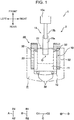
- FIG. 1 is a schematic plan view illustrating a construction machine 1 according to the embodiment.
- FIG. 2 is a block diagram illustrating a control system 3 that the construction machine 1 illustrated in FIG. 1 is equipped with.
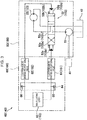
- FIG. 3 is a diagram of a hydraulic circuit for operating a vehicle body 2 of the construction machine 1 illustrated in FIG. 1 .
- the construction machine 1 is a machine that performs construction work, for example, digging.
- the construction machine 1 is a hydraulic excavator.
- the construction machine 1 is not limited to a hydraulic excavator but may be a travelling crane.
- the construction machine 1 includes the vehicle body 2 and the control system 3 (see FIG. 2 ).
- the vehicle body 2 includes an upper slewing body 10 and a lower travelling body 20.
- the lower travelling body 20 drives the construction machine 1.
- the lower travelling body 20 includes a lower body 21 and a pair of crawlers 22 (moving section).
- the crawlers 22 are attached to the left side and the right side of the lower body 21.
- the direction in which the crawler 22 extends is a front-and-rear direction (A) of the lower travelling body 20.
- the front-and-rear direction (A) of the lower travelling body 20 one direction is defined as a forward direction (A1) of the lower travelling body 20 and the opposite direction is defined as a rearward direction (A2) of the lower travelling body 20.
- a hydraulic motor 23 (see FIG. 3 ) for operating the crawler 22 is provided in the rear part of the lower travelling body 20.
- the upper slewing body 10 (moving section) slews about the slew center O relative to the lower travelling body 20.
- the upper slewing body 10 is mounted on the lower body 21 via a slewing device (not shown).
- the upper slewing body 10 includes an upper body 11, a cabin (not shown), and a counter weight 12.
- An upper attachment 15 is attached to the upper slewing body 10.
- a front-and-rear direction (B) of the upper slewing body 10 the direction from the counter weight 12 to the upper attachment 15 is defined as a forward direction (B1) of the upper slewing body 10 and the opposite direction is defined as a rearward direction (B2) of the upper slewing body 10.
- the direction perpendicular to both a vertical direction (D) (direction normal to the sheet on which FIG. 1 is drawn) and the front-and-rear direction (B) of the upper slewing body 10 is defined as a lateral direction (C) of the upper slewing body 10.
- a lateral direction (C) of the upper slewing body 10 the leftward direction, when the upper slewing body 10 is viewed from the rear side, is defined as a leftward direction (C1) of the upper slewing body 10 and the rightward direction is defined as a rightward direction (C2) of the upper slewing body 10.
- the upper body 11 is a main part of the upper slewing body 10. Components such as an engine (not shown) are mounted on the upper body 11.
- a cabin is where an operator (a manipulator of the construction machine 1) manipulates to drive the construction machine 1.
- a manipulating lever 63 (see FIG. 3 ) for manipulating the lower travelling body 20 and a manipulating lever 163 (see FIG. 3 ) for manipulating the upper slewing body 10 are provided in the cabin.
- the counter weight 12 is for adjusting the weight balance of the construction machine 1 along the front-and-rear direction.
- the counter weight 12 is provided in the rear part of the upper body 11.
- the upper attachment 15 is provided in, for example, the front part of the upper body 11 to perform a work, such as digging.
- the upper attachment 15 includes a boom 15a, an arm 15b, and a bucket 15c.
- the construction machine 1 includes a hydraulic circuit 40 for operating the lower travelling body 20 and a hydraulic circuit 140 for operating the upper slewing body 10 as illustrated in FIG 3 . Since the hydraulic circuit 40 and the hydraulic circuit 140 are configured almost the same, reference signs related to the configuration of the hydraulic circuit 140 are written in parentheses in FIG. 3 .
- the hydraulic circuit 40 will be described as a circuit for controlling an operation of the hydraulic motor 23 that drives one of the two crawlers 22.
- the construction machine 1 includes a circuit for controlling an operation of the hydraulic motor 23 that drives the other one of the two crawlers 22.
- This circuit is similar to a drive circuit 50 and a pilot circuit 60, which will be described later, but is provided as a separate circuit.
- a single hydraulic pump 51 may commonly be used for the two drive circuits 50, or alternatively, a single pilot pump may commonly be used for the two pilot circuits 60.
- the hydraulic circuit 40 includes a power source 41, a tank 42, the drive circuit 50, and the pilot circuit 60.
- the power source 41 (engine) is a driving source of the construction machine 1.
- the tank 42 stores oil.
- the drive circuit 50 is for driving the hydraulic motor 23 and includes the hydraulic pump 51, the hydraulic motor 23 (driving mechanism), and a control valve 52.
- the hydraulic pump 51 is driven by the power source 41 to supply oil from the tank 42 to the hydraulic motor 23.
- the hydraulic motor 23 operates the crawler 22 to drive the lower travelling body 20. That is, the hydraulic motor 23 generates a driving force for driving the crawler 22.
- the control valve 52 controls an operation of the hydraulic motor 23.
- the control valve 52 controls the flow rate and the direction of oil supplied from the hydraulic pump 51 to the hydraulic motor 23 to control the operating speed and the operating direction of the hydraulic motor 23.
- the control valve 52 is provided between the hydraulic motor 23 and the hydraulic pump 51.
- the control valve 52 is a three-way switching valve that has three switching positions.
- the control valve 52 is a spool valve in which the valve opening and the switching position are changed according to the position of the spool.
- the control valve 52 is a pilot valve in which the position of the spool changes according to the pilot pressure input to the control valve 52.
- the control valve 52 has different switching positions which are a first operating position 52a, a second operating position 52b, and a neutral position 52c.
- the control valve 52 has a pilot chamber 52p and an opposing pilot chamber 52q.
- the first operating position 52a and the second operating position 52b are for operating the hydraulic motor 23 and where the oil is supplied from the hydraulic pump 51 to the hydraulic motor 23.
- the first operating position 52a is for moving the crawler 22 in the forward direction (A1) of the lower travelling body 20.
- the second operating position 52b is for moving the crawler 22 in the rearward direction (A2) of the lower travelling body 20.
- the neutral position 52c is for stopping the hydraulic motor 23 and where the oil path between the hydraulic pump 51 and the hydraulic motor 23 is cut off.
- the pilot pressure is input to each of the pilot chamber 52p and the opposing pilot chamber 52q.
- the pilot chamber 52p and the opposing pilot chamber 52q are each connected to a pilot pump (not shown).
- the switching position of the control valve 52 is changed according to the difference between the pilot pressure input to the pilot chamber 52p and the pilot pressure input to the opposing pilot chamber 52q.
- the control valve 52 is set to the neutral position 52c when the pilot pressure input to the pilot chamber 52p is equal to the pilot pressure input to the opposing pilot chamber 52q.
- the control valve 52 is set to the first operating position 52a.
- the control valve 52 is set to the second operating position 52b.
- the pilot circuit 60 controls the pilot pressure.
- the pilot circuit 60 includes the pilot pump (not shown), two electromagnetic inverse-proportional valves 61 and 62, the manipulating lever 63, and a manipulation detecting unit 64.
- the manipulation detecting unit 64 includes six pressure sensors 65 and 66. Two of the six pressure sensors 65 and 66 are included in the single pilot circuit 60. Among the other four pressure sensors 65 and 66, two pressure sensors 65 and 66 are included in the pilot circuit 60 for driving the other crawler 22 and the other pressure sensors 65 and 66 are included in a pilot circuit 160 for slewing the upper slewing body 10.
- the two pressure sensors 65 and 66 included in the pilot circuit 60 are disposed to measure the pressure value of the oil path connecting the manipulating lever 63 and the pilot chamber 52p and the pressure value of the oil path connecting the manipulating lever 63 and the opposing pilot chamber 52q.
- the manipulation detecting unit 64 detects the pressure applied, with the manipulating lever 63 manipulated by an operator, to the primary side of the electromagnetic inverse-proportional valves 61 and 62, and outputs the pressure to a controller 31 which will be described later.
- the pilot pump is connected to the pilot chamber 52p and the opposing pilot chamber 52q via the manipulating lever 63 and the electromagnetic inverse-proportional valves 61 and 62.
- the pilot pump is driven by the power source 41 to supply the oil from the tank 42 to the pilot chamber 52p and the opposing pilot chamber 52q.
- the manipulating lever 63 is a manipulation device manipulated by an operator of the construction machine 1 to generate hydraulic pressure corresponding to the degree of lever movement made by the operator.
- the manipulating lever 63 is manipulated to drive the crawler 22 and the upper slewing body 10.
- the hydraulic pressure is supplied from the pilot pump only to the pilot chamber 52p via the electromagnetic inverse-proportional valve 61.
- the control valve 52 is thereby set to the first operating position 52a.
- By pushing rearward the manipulating lever 63 the hydraulic pressure is supplied from the pilot pump only to the opposing pilot chamber 52q via the electromagnetic inverse-proportional valve 62.
- the control valve 52 is thereby set to the second operating position 52b.
- the manipulating lever 63 When the manipulating lever 63 is not manipulated, the manipulating lever 63 stands upright by itself and the oil paths respectively connected to the pilot chamber 52p and the opposing pilot chamber 52q are in communication with the tank 42, which causes both the pilot chamber 52p and opposing pilot chamber 52q to be in the atmospheric pressure.
- the control valve 52 is thereby set to the neutral position 52c.
- the electromagnetic inverse-proportional valves 61 and 62 reduce a primary pressure supplied by the pilot pump to a pressure not higher than a secondary pressure (arbitrary secondary pressure) as an upper limit corresponding to the input current given by the controller 31.
- a predetermined initial current is supplied to the electromagnetic inverse-proportional valves 61 and 62 to set the secondary pressure to a predetermined upper limit.
- the secondary pressure is set to a limiting value corresponding to the input current given by the controller 31 to the electromagnetic inverse-proportional valves 61 and 62, where the limiting value is smaller than the upper limit.
- the input current (command current) is input to the electromagnetic inverse-proportional valves 61 and 62. Larger the input current to the electromagnetic inverse proportional valves 61 and 62 is, lower the secondary pressure is.
- the electromagnetic inverse-proportional valves 61 and 62 are closed and the hydraulic pressure is not supplied to the pilot chamber 52p and the opposing pilot chamber 52q. That is, traveling of the lower travelling body 20 is stopped.
- the hydraulic circuit 140 has almost the same configuration as the hydraulic circuit 40 for operating the lower travelling body 20. Thus, the component configured the same as that of the hydraulic circuit 40 is appended with the same reference sign and the description thereof is omitted.
- the hydraulic circuit 140 includes the power source 41, the tank 42, a drive circuit 150, and the pilot circuit 160.
- the components such as the power source 41, the tank 42, and the hydraulic pump 51 are used in common by the hydraulic circuit 40 but may be provided as separate components.
- the drive circuit 150 is for driving a slewing motor 123 and includes the hydraulic pump 51, the slewing motor 123, and a control valve 152.
- the hydraulic pump 51 is driven by the power source 41 to supply oil from the tank 42 to the slewing motor 123.
- the slewing motor 123 operates the upper slewing body 10 to slew. That is, the slewing motor 123 generates the driving force for slewing (driving) the upper slewing body 10.
- the control valve 152 controls, in a similar manner as the control valve 52, the operation of the slewing motor 123.
- the operating speed of the slewing motor 123 that is, the slewing speed of the upper slewing body 10 becomes slower for a lower pilot pressure that creates a smaller valve opening.
- the control valve 152 has different switching positions which are a first operating position 152a, a second operating position 152b, and a neutral position 152c.
- the control valve 152 has a pilot chamber 152p and an opposing pilot chamber 152q.
- the first operating position 152a and the second operating position 152b are for operating the slewing motor 123 where the oil is supplied from the hydraulic pump 51 to the slewing motor 123.
- the first operating position 152a is for slewing the upper slewing body 10 rightward (clockwise in FIG. 1 ).
- the second operating position 152b is for slewing the upper slewing body 10 leftward (counterclockwise in FIG. 1 ).
- the neutral position 52c is for stopping the slewing motor 123 where the oil path between the hydraulic pump 51 and the slewing motor 123 is cut off.
- the pilot pressure is input to each of the pilot chamber 152p and the opposing pilot chamber 152q.
- the control valve 152 is set to the neutral position 152c when the pilot pressure input to the pilot chamber 152p is equal to the pilot pressure input to the opposing pilot chamber 152q.
- the control valve 152 is set to the first operating position 152a.
- the control valve 152 is set to the second operating position 152b.
- the pilot circuit 160 configured almost similar to the pilot circuit 60, includes a pilot pump (not shown), two electromagnetic inverse-proportional valves 161 and 162, the manipulating lever 163, and a manipulation detecting unit 64 having two pressure sensors 65 and 66.
- the two pressure sensors 65 and 66 included in the pilot circuit 160 are disposed to measure the pressure value of the oil path connecting the manipulating lever 163 and the pilot chamber 152p and the pressure value of the oil path connecting the manipulating lever 163 and the opposing pilot chamber 152q.
- the manipulation detecting unit 64 detects the pressure supplied to the primary side of the electromagnetic inverse-proportional valves 161 and 162 by an operator manipulating the manipulating lever 163 and outputs the pressure to a controller 31 which will be described later.
- the pilot pump is connected to the pilot chamber 152p and the opposing pilot chamber 152q via the manipulating lever 163 and the electromagnetic inverse-proportional valves 161 and 162.
- the pilot pump is driven by the power source 41 to supply the oil from the tank 42 to the pilot chamber 152p and the opposing pilot chamber 152q. That is, the manipulation detecting unit 64 detects a manipulation given to the manipulation device and outputs a signal corresponding to the manipulation to a controlling unit 31a.
- the manipulating lever 163, configured almost the same as the manipulating lever 63, also generates hydraulic pressure corresponding to the degree of lever movement given by the operator.
- the hydraulic pressure is supplied from the pilot pump only to the pilot chamber 152p via the electromagnetic inverse-proportional valve 161.
- the control valve 152 is thereby set to the first operating position 152a.
- the hydraulic pressure is supplied from the pilot pump only to the opposing pilot chamber 152q via the electromagnetic inverse-proportional valve 162.
- the control valve 152 is thereby set to the second operating position 152b.
- the manipulating lever 163 When the manipulating lever 163 is not manipulated, the manipulating lever 163 stands upright by itself and the oil paths respectively connected to the pilot chamber 152p and the opposing pilot chamber 152q are in communication with the tank 42, which causes both the pilot chamber 152p and opposing pilot chamber 152q to be in the atmospheric pressure.
- the control valve 152 is thereby set to the neutral position 152c.
- the electromagnetic inverse-proportional valves 161 and 162 configured almost the same as the electromagnetic inverse-proportional valves 61 and 62, reduce a primary pressure supplied by the pilot pump to a pressure not higher than a secondary pressure (arbitrary secondary pressure) as an upper limit corresponding to the input current given by the controller 31.
- a predetermined initial current is supplied to the electromagnetic inverse-proportional valves 161 and 162 to set the secondary pressure to a predetermined upper limit.
- the secondary pressure is set to a limiting value corresponding to the input current given by the controller 31 to the electromagnetic inverse-proportional valves 161 and 162, where the limiting value is smaller than the upper limit.
- the input current (command current) is input to the electromagnetic inverse-proportional valves 161 and 162. Larger the input current to the electromagnetic inverse-proportional valves 161 and 162 is, lower the secondary pressure is.
- the electromagnetic inverse-proportional valves 161 and 162 are closed and the hydraulic pressure is not supplied to the pilot chamber 152p and the opposing pilot chamber 152q. That is, slewing of the upper slewing body 10 is stopped.
- the control system 3 detects an obstacle in the periphery of the construction machine 1 and restricts an operation (travelling and slewing) of the construction machine 1.
- the control system 3 includes the controller 31, four obstacle detecting devices 32 (see FIG. 1 , and only one of the obstacle detecting devices 32 is illustrated in FIG. 2 ), the electromagnetic inverse-proportional valves 61, 62, 161, and 162, and the manipulation detecting unit 64.
- Two electromagnetic inverse-proportional valves 61 and two electromagnetic inverse-proportional valves 62 are provided in each pilot circuit 60.
- the controller 31 includes the controlling unit 31a and a storage unit 31b.
- the controlling unit 31a executes input and output of signals, arithmetic (e.g., calculation and determination), and control to control slewing of the upper slewing body 10 and travelling of the lower travelling body 20. Based on the information on the distance to the obstacle detected by the four obstacle detecting devices 32, the controlling unit 31a stops slewing of the upper slewing body 10 and travelling of the lower travelling body 20. To stop the operations of the upper slewing body 10 and the lower travelling body 20, the controlling unit 31a inputs an upper limit current to the electromagnetic inverse-proportional valves 61, 62, 161, and 162. The controlling unit 31a controls operations of the hydraulic motor 23 and the slewing motor 123.
- arithmetic e.g., calculation and determination
- the controlling unit 31a includes a stop-processing unit that executes stop-processing (emergency-stop-processing) and continuous-stop-processing, a storage-processing unit that executes storage-processing, a deletion-processing unit that executes deletion-processing, and a determination unit that executes determination-processing and obstacle-determination-processing. Each processing will be described later.
- the storage unit 31b stores information and is provided as a memory area of the controller 31.
- the storage unit 31b stores area-data, which is the data related to a stop-area R previously determined in the periphery of the upper slewing body 10. As illustrated in FIG. 1 , the stop-area R is determined in a further rear region, in the front-and-rear direction (B) of the upper slewing body 10, than the front end of the upper slewing body 10.
- the stop-area R is determined in the periphery of the upper slewing body 10 to form a U-shape.
- the area-data does not include the area occupied by the lower travelling body 20.
- the storage unit 31b stores a manipulate-instruction (manipulate-instruction based on pressure values output from the pressure sensors 65 and 66 to instruct the direction to which the lower travelling body 20 travels and the direction to which the upper slewing body 10 slews) that is given when the stop-processing, which will be described later, is executed.
- a manipulate-instruction manipulate-instruction based on pressure values output from the pressure sensors 65 and 66 to instruct the direction to which the lower travelling body 20 travels and the direction to which the upper slewing body 10 slews
- the manipulate-instruction stored in the storage unit 31b is deleted by executing a manipulation different from the stored manipulate-instruction (for example, by returning the manipulating lever 63 or 163 to the upright position (neutral position) where the manipulating lever 63 or 163 stands upright by itself).
- each obstacle detecting device 32 can detect an obstacle (that is, an object or a person) in the stop-area R defined in the periphery of the construction machine 1.
- the four obstacle detecting devices 32 are mounted on the upper portion, with regard to the vertical direction (D), of the upper slewing body 10.
- the two obstacle detecting devices 32 are provided on the left side and the right side of the front end of the upper slewing body 10
- the two obstacle detecting devices 32 are provided on the left side and the right side of the rear end (counter weight 12) of the upper slewing body 10.
- the four obstacle detecting devices 32 detect an obstacle in the stop-area R.
- the obstacle detecting device 32 is a three-dimensional range sensor that can obtain an image and a distance.
- the obstacle detecting device 32 is not limited and may be any sensor that can detect whether an obstacle exists in the stop-area R (for example, a pyroelectric sensor).
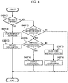
- FIG. 4 is a control flowchart related to stopping an operation of the construction machine 1 illustrated in FIG. 1 .
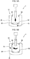
- FIGS. 5A and 5B illustrate an obstacle existing in a peripheral region of the vehicle body 2 of the construction machine 1 illustrated in FIG. 1 .
- FIG. 5A illustrates the lower travelling body 20 moving backward.
- FIG. 5B illustrates the upper slewing body 10 slewing rightward.
- the controlling unit 31a determines whether an obstacle G exists in the stop-area R based on information on a distance, which is the distance to the obstacle G, detected by the obstacle detecting device 32 in step S1 as illustrated in FIG. 4 (obstacle-determination-processing). As illustrated in FIG. 5A , the processing proceeds to step S2 when the obstacle G exists in the stop-area R (YES in step S1).
- step S2 the controlling unit 31a stores the manipulate-instruction that is output from the manipulation detecting unit 64 (first manipulation information: a manipulate-instruction to move the lower travelling body 20 backward in this case) in the storage unit 31b (storage-processing).
- first manipulation information a manipulate-instruction to move the lower travelling body 20 backward in this case
- the storage unit 31b storage-processing
- step S3 the controlling unit 31a supplies an upper limit current to the electromagnetic inverse-proportional valves 61 and 62 to close the electromagnetic inverse-proportional valves 61 and 62, thereby executing the control of stopping the travelling of the lower travelling body 20 (stop-processing or emergency-stop-processing). The process thus ends.
- step S1 The obstacle-determination-processing (step S1) is repeated while the engine of the construction machine 1 is running.
- the processing proceeds to step S4 when the obstacle G does not exist in the stop-area R in step S1 (NO in step S1).
- step S4 the controlling unit 31a determines whether the storage unit 31b stores the manipulate-instruction.
- the manipulate-instruction is not stored in the storage unit 31b (NO in step S4), and the process ends. With no obstacle G existing in the stop-area R, the lower travelling body 20 continues travelling.
- step S2 proceeds from step S2 to step S3, and when the stop-processing has been executed, the manipulate-instruction is stored in the storage unit 31b. Then, step S1 is executed again and the processing proceeds from step S1 to step S4. While the stop-processing is still being executed, when the obstacle G is not detected in the stop-area R but the manipulate-instruction is stored in the storage unit 31b in step S4 (YES in step S4), the processing proceeds to step S5.
- step S5 the controlling unit 31a determines whether the previous manipulate-instruction stored in the storage unit 31b (the first manipulation information: the manipulate-instruction to move the lower travelling body 20 backward) corresponds with the current manipulate-instruction newly detected by the manipulation detecting unit 64 (second manipulation information) (determination-processing).
- the current manipulate-instruction continues from the previous manipulate-instruction, it is determined that both manipulate-instructions correspond with each other (YES in step S5), and the proceeding proceeds to step S6.
- step S6 the controlling unit 31a supplies the upper limit current to the electromagnetic inverse-proportional valves 61 and 62 to close the electromagnetic inverse-proportional valves 61 and 62, and thereby executes the control of stopping the travelling of the lower travelling body 20 (continuous-stop-processing).
- the control executed to perform the continuous-stop-processing is similar to the control executed to perform the emergency-stop-processing, and thus the control is not needed to be executed again.
- the controlling unit 31a may simply continue the control to continue the emergency-stop-processing. The process thus ends.
- step S5 for example, when the operator returns the manipulating lever 63 to the neutral position to stop manipulating, the current manipulate-instruction (the second manipulation information) does not correspond with the previous manipulate-instruction (the first manipulation information) (NO in step S5), and the processing proceeds to step S7.
- the controlling unit 31a deletes the manipulate-instruction stored in the storage unit 31b when the predetermined condition that the manipulate-instructions do not correspond with each other is satisfied in the determination-processing in step S5 (deletion-processing). How to delete the manipulate-instruction stored in the storage unit 31b is not limited.
- the controlling unit 31a may delete the manipulate-instruction stored in the storage unit 31b by manipulating a lever-lock (not shown) in the operator's room or by the operator pushing a dedicated reset switch.
- the predetermined condition to execute the deletion-processing may be any condition that includes operator's stopping manipulation of the manipulating lever 63 when the stop-processing is executed.
- step S8 the controlling unit 31a supplies a predetermined initial current to the electromagnetic inverse-proportional valves 61 and 62 to cancel the stopping of the travelling of the lower travelling body 20. As a result, the lower travelling body 20 can travel normally. The process thus ends.
- control flowchart of slewing the upper slewing body 10 rightward by an operator manipulating the manipulating lever 163 will now be described.
- the control flowchart is similar to the control flowchart of the lower travelling body 20, and thus the control flowchart will be described below with reference to FIG. 4 .
- the controlling unit 31a determines whether an obstacle G exists in the stop-area R based on information on a distance, which is the distance to the obstacle G detected by the obstacle detecting device 32 in step F1 as illustrated in FIG. 4 (obstacle-determination-processing). As illustrated in FIG. 5B , the processing proceeds to step F2 when the obstacle G exists in the stop-area R (YES in step F1).
- step F2 the controlling unit 31a stores the manipulate-instruction output from the manipulation detecting unit 64 (first manipulation information: a manipulate-instruction to slew the upper slewing body 10 rightward in this case) in the storage unit 31b (storage-processing).
- first manipulation information a manipulate-instruction to slew the upper slewing body 10 rightward in this case
- the storage unit 31b storage-processing
- the controlling unit 31a stores the manipulate-instruction given when the upper slewing body 10 is stopped in the storage unit 31b in step F2.
- step F3 the controlling unit 31a supplies an upper limit current to the electromagnetic inverse-proportional valves 161 and 162 to close the electromagnetic inverse-proportional valves 161 and 162, thereby executing the control of stopping the slewing of the upper slewing body 10 (stop-processing or emergency-stop-processing). The process thus ends.
- Step F1 is repeated, and the proceeding proceeds to step F4, similar to step S4 described above, when the obstacle G does not exist in the stop-area R (NO in step F1).
- step F4 when the stop-processing is not executed, the manipulate-instruction is not stored in the storage unit 31b (NO in step F4), and the process ends. With no obstacle G existing in the stop-area R, the upper slewing body 10 continues slewing.
- step F1 When the proceeding proceeds from step F1 to step F4 while the stop-processing is being executed, the manipulate-instruction is stored in the storage unit 31b. That is, the processing proceeds to step F5 when the manipulate-instruction is stored in the storage unit 31b in step F4 (YES in step F4).
- step F5 in a manner similar to step S5, the controlling unit 31a determines whether the previous manipulate-instruction stored in the storage unit 31b (first manipulation information: a manipulate-instruction to slew the upper slewing body 10 rightward) corresponds with the current manipulate-instruction detected by the manipulation detecting unit 64 (second manipulation information) (determination-processing).
- first manipulation information a manipulate-instruction to slew the upper slewing body 10 rightward
- second manipulation information second manipulation information
- step F6 in a manner similar to step S6, the controlling unit 31a supplies the upper limit current to the electromagnetic inverse-proportional valves 161 and 162 to close the electromagnetic inverse-proportional valves 161 and 162, and thereby executes the control of stopping the slewing of the upper slewing body 10 (continuous-stop-processing). In this manner, the present stop-processing continues.
- the continuous-stop-processing is similar to the emergency-stop-processing, and thus the control is not needed to be executed again. In this case, the controlling unit 31a may simply continue the control to continue the stop-processing. The process thus ends.
- step F5 when the operator returns the manipulating lever 163 to the neutral position to stop manipulating, the current manipulate-instruction does not correspond with the previous manipulate-instruction (NO in step F5), and the processing proceeds to step F7 similar to step S7.
- step F7 the controlling unit 31a deletes the manipulate-instruction stored in the storage unit 31b (deletion-processing).
- step F8 in a manner similar to step S8, the controlling unit 31a supplies a predetermined initial current to the electromagnetic inverse-proportional valves 161 and 162 to cancel the stopping of the slewing of the upper slewing body 10.
- the upper slewing body 10 can slew normally. The process thus ends.
- the continuous-stop-processing is performed to continue the stop-processing executed in step S6 or F6 when the manipulate-instruction detected by the manipulation detecting unit 64 continues.
- the stop-processing continues and thus collision against the obstacle G is prevented. This improves safety.
- step S5 or F5 when the manipulate-instructions correspond with each other in the determination-processing in step S5 or F5, the processing in step S6 or F6 continues. In this manner, determination of whether to continue the stop-processing can be performed by a simple configuration.
- step S7 or F7 the controlling unit 31a executes the deletion-processing of deleting the manipulate-instruction stored in the storage unit 31b when the predetermined condition that the manipulate-instructions correspond with each other is satisfied in the determination-processing in step S5 or F5.
- the manipulate-instruction stored in the storage unit 31b is deleted when a manipulation that is different from the manipulate-instruction stored in the storage unit 31b is preformed, such as when an operator finishes manipulating the manipulating lever 63 or 163.
- the vehicle body 2 includes the lower travelling body 20 and the upper slewing body 10.
- the lower travelling body 20 and the upper slewing body 10 are operated by the manipulating levers 63 and 163.
- the construction machine 1 including the lower travelling body 20 and the upper slewing body 10 even when the obstacle is temporarily not detected while the stop-processing is being executed, the stop-processing continues and thus collision against the obstacle is prevented. This improves safety.
- the controlling unit 31a determines whether the obstacle G exists in the stop-area R based on the information on a distance from the obstacle detecting device 32. In this manner, the stop-processing is executed according to the distance to the obstacle G.
- the stop-processing is executed when the obstacle G is detected in the stop-area R while the upper slewing body 10 is operated to slew and the lower travelling body 20 is operated to travel.
- the stop-processing may be executed when only either one of the operations is performed.
- the moving section of the vehicle body 2 may be a section other than the slewing section of the upper slewing body 10 and the travelling section of the lower travelling body 20.
- whether the obstacle G exists in the stop-area R may be determined in the obstacle-determination-processing in steps S1 and F1 based on whether the obstacle detecting device 32 detects the obstacle G.
- the vehicle body 2 of the construction machine 1 may be a vehicle body that cannot slew, namely, the vehicle body that can only travel. Also, in this case, the control is executed in a similar manner to the stop-control executed as described above when the lower travelling body 20 is travelling.
- the vehicle body 2 of the construction machine 1 may be a vehicle body that cannot travel, namely, the vehicle body that can only slew. Also, in this case, the control is executed in a similar manner to the stop-control executed as described above when the upper slewing body 10 is slewing. Also, in this case, an effect similar to the effect described above can be obtained.
- the determination-processing in steps S5 and F5 may be executed simply by determining whether the same signal is output from the manipulation detecting unit 64 to the controlling unit 31a. That is, determination may be made not by comparing the previous manipulate-instruction stored in the storage unit 31b (the first manipulation information) with the current manipulate-instruction (the second manipulation information) but by determining whether the same signal is continuously being output from the manipulation detecting unit 64. In this case, the stop-processing may be cancelled when a different signal is output from the manipulation detecting unit 64. Alternatively, only a single obstacle detecting device 32 may be provided.
- the present invention provides a construction machine including a vehicle body having a moving section, a driving mechanism that generates a driving force for driving the moving section, a manipulation device that receives a manipulation given to drive the moving section, a controlling unit that controls an operation of the driving mechanism, a manipulation detecting unit that detects the manipulation given to the manipulation device and outputs a signal corresponding to an instruction of the manipulation to the controlling unit, and an obstacle detecting device that is mounted on the vehicle body and detects an obstacle in a periphery of the vehicle body.
- the controlling unit executes emergency-stop-processing and continuous-stop-processing, the emergency-stop-processing being executed to control the driving mechanism to stop an operation of the moving section regardless of a signal from the manipulation detecting unit, on a first condition satisfied upon detection of the obstacle by the obstacle detecting device when the controlling unit receives the signal from the manipulation detecting unit to control the driving mechanism to drive the moving section in accordance with a manipulation input to the manipulation device , the continuous-stop-processing being executed to control the driving mechanism to keep the operation of the moving section, which has been stopped by the emergency-stop-processing, stopped on a second condition satisfied by the obstacle detecting device not detecting the obstacle and the manipulation detecting unit detecting a manipulation given to the manipulation device when the operation of the moving section is stopped by the emergency-stop-processing.
- the construction machine further includes a storage unit that stores an instruction of manipulation given to the manipulation device, in which the controlling unit is further capable of executing storage-processing, deletion-processing, and determination-processing, the storage-processing being executed to store first manipulation information in the storage unit, the first manipulation information being an instruction of the manipulation detected by the manipulation detecting unit when the emergency-stop-processing is executed, the deletion-processing being executed to delete the first manipulation information stored in the storage unit when a predetermined condition is satisfied, the determination-processing being executed to determine whether the first manipulation information stored in the storage unit corresponds with second manipulation information that is an instruction of the manipulation newly detected by the manipulation detecting unit when the emergency-stop-processing is executed and the obstacle detecting device does not detect the obstacle, and the controlling unit executes the continuous-stop-processing when the second condition is satisfied and it is determined that the first manipulation information corresponds with the second manipulation information in the determination-processing.
- the controlling unit executes the continuous-stop-processing when the second condition is satisfied and it is determined that the first manipulation information correspond
- the predetermined condition may be satisfied when it is determined in the determination-processing that the first manipulation information corresponds with the second manipulation information.
- the vehicle body includes a lower travelling body that travels, and an upper slewing body that slews relative to the lower travelling body, and the manipulation device may receive a manipulation given to at least drive the lower travelling body serving as the moving section or slew the upper slewing body serving as the moving section.
- the obstacle detecting device outputs to the controlling unit the information on a distance to the obstacle which is detected, the controlling unit further executes obstacle-determination-processing of determining whether the obstacle exists in a predetermined stop-area in a periphery of the vehicle body based on the information on a distance from the obstacle detecting device to the obstacle, and the controlling unit executes the emergency-stop-processing when it is determined in the obstacle-determination-processing that the obstacle exists in the stop-area and that the first condition is satisfied by the obstacle detecting device detecting the obstacle.
- a construction machine includes a vehicle body having, a moving section, a driving mechanism, a manipulation device that receives a manipulation, a controlling unit, a manipulation detecting unit that detects the manipulation given to the manipulation device, and an obstacle detecting device that detects an obstacle in a periphery of the vehicle body.
- the controlling unit executes emergency-stop-processing and continuous-stop-processing.
- the emergency-stop-processing is executed to stop the operation of the moving section regardless of a signal from the manipulation detecting unit upon detection of the obstacle by the obstacle detecting device when the controlling unit controls the driving mechanism to drive the moving section.
- the continuous-stop-processing is executed to keep the operation of the moving section stopped when the obstacle detecting device does not detect the obstacle and the manipulation detecting unit detects manipulation when the operation of the moving section is stopped by the emergency-stop-processing.
Landscapes
- Engineering & Computer Science (AREA)
- Mining & Mineral Resources (AREA)
- Civil Engineering (AREA)
- General Engineering & Computer Science (AREA)
- Structural Engineering (AREA)
- Mechanical Engineering (AREA)
- Automation & Control Theory (AREA)
- Transportation (AREA)
- Component Parts Of Construction Machinery (AREA)
- Operation Control Of Excavators (AREA)
Abstract
Description
- The present invention relates to a construction machine.
- Japanese Unexamined Patent Application Publication No.
2007-23486 - In the technique described above, when an operation is forcibly stopped but a manipulation instructing the operation is still being input to a manipulation device, stopping of operation is cancelled and the operation restarts when an obstacle that has been detected in the collision prevention area temporarily exits the area (that is, when a person that has been in the collision prevention area temporarily exits the collision prevention area). When the operation restarts simply by the obstacle temporarily exiting the collision prevention area as described above, the operation cannot be stopped immediately when the obstacle reenters the collision prevention area. This may cause a portion of the upper slewing body colliding against the obstacle. Moreover, in a case where the device for detecting an obstacle is a millimeter-wave radar, an obstacle that is vertically out of the range of the radio wave emitted by the millimeter-wave radar cannot be detected. Therefore, when an obstacle, which is detected in the collision prevention area (within the range of the radio wave), falls down, it is determined that the obstacle has moved outside the collision prevention area. Then stopping of operation is cancelled, and the operation restarts. Restarting of the operation with the obstacle still staying in a place where collision against a portion of the upper slewing body might happen may result in collision between the obstacle and the portion of the upper slewing body.
- An object of the present invention is to provide a construction machine capable of preventing collision against an obstacle.
- Provided is a construction machine including a vehicle body having a moving section, a driving mechanism that generates a driving force to drive the moving section, a manipulation device that receives a manipulation given to drive the moving section, a controlling unit that controls an operation of the driving mechanism, a manipulation detecting unit that detects the manipulation given to the manipulation device and outputs a signal corresponding to an instruction of the manipulation to the controlling unit, and an obstacle detecting device that is mounted on the vehicle body to detect an obstacle in a periphery of the vehicle body, in which the controlling unit executes emergency-stop-processing and continuous-stop-processing, the emergency-stop-processing being executed to control the driving mechanism to stop an operation of the moving section regardless of a signal from the manipulation detecting unit, on a first condition satisfied upon detection of the obstacle by the obstacle detecting device when the controlling unit receives the signal from the manipulation detecting unit to control the driving mechanism to drive the moving section in accordance with a manipulation input to the manipulation device, the continuous-stop-processing being executed to control the driving mechanism to keep the operation of the moving section, which has been stopped by the emergency-stop-processing, stopped on a second condition satisfied by the obstacle detecting device not detecting the obstacle and the manipulation detecting unit detecting a manipulation given to the manipulation device when the operation of the moving section is stopped by the emergency-stop-processing.
-
-
FIG. 1 is a schematic plan view illustrating a construction machine according to an embodiment of the present invention; -
FIG. 2 is a block diagram illustrating a control system that the construction machine illustrated inFIG. 1 is equipped with; -
FIG. 3 is a diagram of a hydraulic circuit for operating a vehicle body of the construction machine illustrated inFIG. 1 ; -
FIG. 4 is a control flowchart related to stopping an operation of the construction machine illustrated inFIG. 1 ; and -
FIGS. 5A and 5B illustrate an obstacle existing in a peripheral region of the vehicle body of the construction machine illustrated inFIG. 1 , in whichFIG. 5A illustrates a lower travelling body moving backward, andFIG. 5B illustrates an upper slewing body slewing rightward. - A construction machine 1 according to an embodiment of the present invention will now be described with reference to
FIGS. 1 to 3 .FIG. 1 is a schematic plan view illustrating a construction machine 1 according to the embodiment.FIG. 2 is a block diagram illustrating acontrol system 3 that the construction machine 1 illustrated inFIG. 1 is equipped with.FIG. 3 is a diagram of a hydraulic circuit for operating avehicle body 2 of the construction machine 1 illustrated inFIG. 1 . The construction machine 1 is a machine that performs construction work, for example, digging. In the embodiment, the construction machine 1 is a hydraulic excavator. The construction machine 1 is not limited to a hydraulic excavator but may be a travelling crane. As illustrated inFIGS. 1 and2 , the construction machine 1 includes thevehicle body 2 and the control system 3 (seeFIG. 2 ). - The
vehicle body 2 includes anupper slewing body 10 and alower travelling body 20. Thelower travelling body 20 drives the construction machine 1. Thelower travelling body 20 includes alower body 21 and a pair of crawlers 22 (moving section). As illustrated inFIG. 1 , thecrawlers 22 are attached to the left side and the right side of thelower body 21. As illustrated inFIG. 1 , the direction in which thecrawler 22 extends is a front-and-rear direction (A) of thelower travelling body 20. With regards to the front-and-rear direction (A) of thelower travelling body 20, one direction is defined as a forward direction (A1) of thelower travelling body 20 and the opposite direction is defined as a rearward direction (A2) of thelower travelling body 20. For example, a hydraulic motor 23 (seeFIG. 3 ) for operating thecrawler 22 is provided in the rear part of thelower travelling body 20. - The upper slewing body 10 (moving section) slews about the slew center O relative to the
lower travelling body 20. Theupper slewing body 10 is mounted on thelower body 21 via a slewing device (not shown). Theupper slewing body 10 includes anupper body 11, a cabin (not shown), and acounter weight 12. Anupper attachment 15 is attached to theupper slewing body 10. With regard to a front-and-rear direction (B) of theupper slewing body 10, the direction from thecounter weight 12 to theupper attachment 15 is defined as a forward direction (B1) of theupper slewing body 10 and the opposite direction is defined as a rearward direction (B2) of theupper slewing body 10. The direction perpendicular to both a vertical direction (D) (direction normal to the sheet on whichFIG. 1 is drawn) and the front-and-rear direction (B) of theupper slewing body 10 is defined as a lateral direction (C) of theupper slewing body 10. With regard to the lateral direction (C) of theupper slewing body 10, the leftward direction, when theupper slewing body 10 is viewed from the rear side, is defined as a leftward direction (C1) of theupper slewing body 10 and the rightward direction is defined as a rightward direction (C2) of theupper slewing body 10. - The
upper body 11 is a main part of theupper slewing body 10. Components such as an engine (not shown) are mounted on theupper body 11. A cabin is where an operator (a manipulator of the construction machine 1) manipulates to drive the construction machine 1. A manipulating lever 63 (seeFIG. 3 ) for manipulating thelower travelling body 20 and a manipulating lever 163 (seeFIG. 3 ) for manipulating theupper slewing body 10 are provided in the cabin. Thecounter weight 12 is for adjusting the weight balance of the construction machine 1 along the front-and-rear direction. Thecounter weight 12 is provided in the rear part of theupper body 11. Theupper attachment 15 is provided in, for example, the front part of theupper body 11 to perform a work, such as digging. For example, theupper attachment 15 includes aboom 15a, anarm 15b, and abucket 15c. - The construction machine 1 includes a
hydraulic circuit 40 for operating thelower travelling body 20 and ahydraulic circuit 140 for operating theupper slewing body 10 as illustrated inFIG 3 . Since thehydraulic circuit 40 and thehydraulic circuit 140 are configured almost the same, reference signs related to the configuration of thehydraulic circuit 140 are written in parentheses inFIG. 3 . Thehydraulic circuit 40 will be described as a circuit for controlling an operation of thehydraulic motor 23 that drives one of the twocrawlers 22. The construction machine 1 includes a circuit for controlling an operation of thehydraulic motor 23 that drives the other one of the twocrawlers 22. This circuit is similar to adrive circuit 50 and a pilot circuit 60, which will be described later, but is provided as a separate circuit. A singlehydraulic pump 51 may commonly be used for the twodrive circuits 50, or alternatively, a single pilot pump may commonly be used for the two pilot circuits 60. - As illustrated in
FIG. 3 , thehydraulic circuit 40 includes apower source 41, atank 42, thedrive circuit 50, and the pilot circuit 60. The power source 41 (engine) is a driving source of the construction machine 1. Thetank 42 stores oil. Thedrive circuit 50 is for driving thehydraulic motor 23 and includes thehydraulic pump 51, the hydraulic motor 23 (driving mechanism), and acontrol valve 52. Thehydraulic pump 51 is driven by thepower source 41 to supply oil from thetank 42 to thehydraulic motor 23. - The
hydraulic motor 23 operates thecrawler 22 to drive the lower travellingbody 20. That is, thehydraulic motor 23 generates a driving force for driving thecrawler 22. Thecontrol valve 52 controls an operation of thehydraulic motor 23. Thecontrol valve 52 controls the flow rate and the direction of oil supplied from thehydraulic pump 51 to thehydraulic motor 23 to control the operating speed and the operating direction of thehydraulic motor 23. Thecontrol valve 52 is provided between thehydraulic motor 23 and thehydraulic pump 51. Thecontrol valve 52 is a three-way switching valve that has three switching positions. Thecontrol valve 52 is a spool valve in which the valve opening and the switching position are changed according to the position of the spool. Thecontrol valve 52 is a pilot valve in which the position of the spool changes according to the pilot pressure input to thecontrol valve 52. In more detail, the operating speed of thehydraulic motor 23, that is, the travelling speed of the lower travellingbody 20, becomes slower for a lower pilot pressure that creates a smaller valve opening. Thecontrol valve 52 has different switching positions which are afirst operating position 52a, asecond operating position 52b, and aneutral position 52c. Thecontrol valve 52 has apilot chamber 52p and an opposingpilot chamber 52q. - The
first operating position 52a and thesecond operating position 52b are for operating thehydraulic motor 23 and where the oil is supplied from thehydraulic pump 51 to thehydraulic motor 23. Thefirst operating position 52a is for moving thecrawler 22 in the forward direction (A1) of the lower travellingbody 20. Thesecond operating position 52b is for moving thecrawler 22 in the rearward direction (A2) of the lower travellingbody 20. Theneutral position 52c is for stopping thehydraulic motor 23 and where the oil path between thehydraulic pump 51 and thehydraulic motor 23 is cut off. - The pilot pressure is input to each of the
pilot chamber 52p and the opposingpilot chamber 52q. Thepilot chamber 52p and the opposingpilot chamber 52q are each connected to a pilot pump (not shown). The switching position of thecontrol valve 52 is changed according to the difference between the pilot pressure input to thepilot chamber 52p and the pilot pressure input to the opposingpilot chamber 52q. Thecontrol valve 52 is set to theneutral position 52c when the pilot pressure input to thepilot chamber 52p is equal to the pilot pressure input to the opposingpilot chamber 52q. When the pilot pressure input to thepilot chamber 52p is higher than the pilot pressure input to the opposingpilot chamber 52q, thecontrol valve 52 is set to thefirst operating position 52a. When the pilot pressure input to the opposingpilot chamber 52q is higher than the pilot pressure input to thepilot chamber 52p, thecontrol valve 52 is set to thesecond operating position 52b. - The pilot circuit 60 controls the pilot pressure. The pilot circuit 60 includes the pilot pump (not shown), two electromagnetic inverse-
proportional valves lever 63, and amanipulation detecting unit 64. Themanipulation detecting unit 64 includes sixpressure sensors pressure sensors pressure sensors pressure sensors other crawler 22 and theother pressure sensors upper slewing body 10. The twopressure sensors lever 63 and thepilot chamber 52p and the pressure value of the oil path connecting the manipulatinglever 63 and the opposingpilot chamber 52q. Themanipulation detecting unit 64 detects the pressure applied, with the manipulatinglever 63 manipulated by an operator, to the primary side of the electromagnetic inverse-proportional valves controller 31 which will be described later. The pilot pump is connected to thepilot chamber 52p and the opposingpilot chamber 52q via the manipulatinglever 63 and the electromagnetic inverse-proportional valves power source 41 to supply the oil from thetank 42 to thepilot chamber 52p and the opposingpilot chamber 52q. - The manipulating
lever 63 is a manipulation device manipulated by an operator of the construction machine 1 to generate hydraulic pressure corresponding to the degree of lever movement made by the operator. The manipulatinglever 63 is manipulated to drive thecrawler 22 and theupper slewing body 10. By pushing forward the manipulatinglever 63 according to the embodiment, the hydraulic pressure is supplied from the pilot pump only to thepilot chamber 52p via the electromagnetic inverse-proportional valve 61. Thecontrol valve 52 is thereby set to thefirst operating position 52a. By pushing rearward the manipulatinglever 63, the hydraulic pressure is supplied from the pilot pump only to the opposingpilot chamber 52q via the electromagnetic inverse-proportional valve 62. Thecontrol valve 52 is thereby set to thesecond operating position 52b. When the manipulatinglever 63 is not manipulated, the manipulatinglever 63 stands upright by itself and the oil paths respectively connected to thepilot chamber 52p and the opposingpilot chamber 52q are in communication with thetank 42, which causes both thepilot chamber 52p and opposingpilot chamber 52q to be in the atmospheric pressure. Thecontrol valve 52 is thereby set to theneutral position 52c. - The electromagnetic inverse-
proportional valves controller 31. In a case without restriction on traveling of the lower travellingbody 20, a predetermined initial current is supplied to the electromagnetic inverse-proportional valves body 20, the secondary pressure is set to a limiting value corresponding to the input current given by thecontroller 31 to the electromagnetic inverse-proportional valves proportional valves proportional valves controller 31 to the electromagnetic inverse-proportional valves proportional valves pilot chamber 52p and the opposingpilot chamber 52q. That is, traveling of the lower travellingbody 20 is stopped. - The
hydraulic circuit 140 has almost the same configuration as thehydraulic circuit 40 for operating the lower travellingbody 20. Thus, the component configured the same as that of thehydraulic circuit 40 is appended with the same reference sign and the description thereof is omitted. As illustrated inFIG. 3 , thehydraulic circuit 140 includes thepower source 41, thetank 42, adrive circuit 150, and the pilot circuit 160. The components such as thepower source 41, thetank 42, and thehydraulic pump 51 are used in common by thehydraulic circuit 40 but may be provided as separate components. Thedrive circuit 150 is for driving a slewingmotor 123 and includes thehydraulic pump 51, the slewingmotor 123, and acontrol valve 152. Thehydraulic pump 51 is driven by thepower source 41 to supply oil from thetank 42 to the slewingmotor 123. - The slewing
motor 123 operates theupper slewing body 10 to slew. That is, the slewingmotor 123 generates the driving force for slewing (driving) theupper slewing body 10. Thecontrol valve 152 controls, in a similar manner as thecontrol valve 52, the operation of the slewingmotor 123. In more detail, the operating speed of the slewingmotor 123, that is, the slewing speed of theupper slewing body 10, becomes slower for a lower pilot pressure that creates a smaller valve opening. Thecontrol valve 152 has different switching positions which are afirst operating position 152a, asecond operating position 152b, and aneutral position 152c. Thecontrol valve 152 has apilot chamber 152p and an opposingpilot chamber 152q. - The
first operating position 152a and thesecond operating position 152b are for operating the slewingmotor 123 where the oil is supplied from thehydraulic pump 51 to the slewingmotor 123. Thefirst operating position 152a is for slewing theupper slewing body 10 rightward (clockwise inFIG. 1 ). Thesecond operating position 152b is for slewing theupper slewing body 10 leftward (counterclockwise inFIG. 1 ). Theneutral position 52c is for stopping the slewingmotor 123 where the oil path between thehydraulic pump 51 and the slewingmotor 123 is cut off. - The pilot pressure is input to each of the
pilot chamber 152p and the opposingpilot chamber 152q. Thecontrol valve 152 is set to theneutral position 152c when the pilot pressure input to thepilot chamber 152p is equal to the pilot pressure input to the opposingpilot chamber 152q. When the pilot pressure input to thepilot chamber 152p is higher than the pilot pressure input to the opposingpilot chamber 152q, thecontrol valve 152 is set to thefirst operating position 152a. When the pilot pressure input to the opposingpilot chamber 152q is higher than the pilot pressure input to thepilot chamber 152p, thecontrol valve 152 is set to thesecond operating position 152b. - The pilot circuit 160, configured almost similar to the pilot circuit 60, includes a pilot pump (not shown), two electromagnetic inverse-
proportional valves lever 163, and amanipulation detecting unit 64 having twopressure sensors pressure sensors lever 163 and thepilot chamber 152p and the pressure value of the oil path connecting the manipulatinglever 163 and the opposingpilot chamber 152q. Themanipulation detecting unit 64 detects the pressure supplied to the primary side of the electromagnetic inverse-proportional valves lever 163 and outputs the pressure to acontroller 31 which will be described later. The pilot pump is connected to thepilot chamber 152p and the opposingpilot chamber 152q via the manipulatinglever 163 and the electromagnetic inverse-proportional valves power source 41 to supply the oil from thetank 42 to thepilot chamber 152p and the opposingpilot chamber 152q. That is, themanipulation detecting unit 64 detects a manipulation given to the manipulation device and outputs a signal corresponding to the manipulation to a controllingunit 31a. - The manipulating
lever 163, configured almost the same as the manipulatinglever 63, also generates hydraulic pressure corresponding to the degree of lever movement given by the operator. By pushing rightward the manipulatinglever 163 according to the embodiment, the hydraulic pressure is supplied from the pilot pump only to thepilot chamber 152p via the electromagnetic inverse-proportional valve 161. Thecontrol valve 152 is thereby set to thefirst operating position 152a. By pushing leftward the manipulatinglever 163, the hydraulic pressure is supplied from the pilot pump only to the opposingpilot chamber 152q via the electromagnetic inverse-proportional valve 162. Thecontrol valve 152 is thereby set to thesecond operating position 152b. When the manipulatinglever 163 is not manipulated, the manipulatinglever 163 stands upright by itself and the oil paths respectively connected to thepilot chamber 152p and the opposingpilot chamber 152q are in communication with thetank 42, which causes both thepilot chamber 152p and opposingpilot chamber 152q to be in the atmospheric pressure. Thecontrol valve 152 is thereby set to theneutral position 152c. - The electromagnetic inverse-
proportional valves proportional valves controller 31. In a case without restriction on slewing of theupper slewing body 10, a predetermined initial current is supplied to the electromagnetic inverse-proportional valves upper slewing body 10, the secondary pressure is set to a limiting value corresponding to the input current given by thecontroller 31 to the electromagnetic inverse-proportional valves proportional valves proportional valves controller 31 to the electromagnetic inverse-proportional valves proportional valves pilot chamber 152p and the opposingpilot chamber 152q. That is, slewing of theupper slewing body 10 is stopped. - The
control system 3 detects an obstacle in the periphery of the construction machine 1 and restricts an operation (travelling and slewing) of the construction machine 1. As illustrated inFIG. 2 , thecontrol system 3 includes thecontroller 31, four obstacle detecting devices 32 (seeFIG. 1 , and only one of theobstacle detecting devices 32 is illustrated inFIG. 2 ), the electromagnetic inverse-proportional valves manipulation detecting unit 64. Two electromagnetic inverse-proportional valves 61 and two electromagnetic inverse-proportional valves 62 are provided in each pilot circuit 60. Thecontroller 31 includes the controllingunit 31a and astorage unit 31b. - The controlling
unit 31a executes input and output of signals, arithmetic (e.g., calculation and determination), and control to control slewing of theupper slewing body 10 and travelling of the lower travellingbody 20. Based on the information on the distance to the obstacle detected by the fourobstacle detecting devices 32, the controllingunit 31a stops slewing of theupper slewing body 10 and travelling of the lower travellingbody 20. To stop the operations of theupper slewing body 10 and the lower travellingbody 20, the controllingunit 31a inputs an upper limit current to the electromagnetic inverse-proportional valves unit 31a controls operations of thehydraulic motor 23 and the slewingmotor 123. The controllingunit 31a includes a stop-processing unit that executes stop-processing (emergency-stop-processing) and continuous-stop-processing, a storage-processing unit that executes storage-processing, a deletion-processing unit that executes deletion-processing, and a determination unit that executes determination-processing and obstacle-determination-processing. Each processing will be described later. - The
storage unit 31b stores information and is provided as a memory area of thecontroller 31. Thestorage unit 31b stores area-data, which is the data related to a stop-area R previously determined in the periphery of theupper slewing body 10. As illustrated inFIG. 1 , the stop-area R is determined in a further rear region, in the front-and-rear direction (B) of theupper slewing body 10, than the front end of theupper slewing body 10. The stop-area R is determined in the periphery of theupper slewing body 10 to form a U-shape. The area-data does not include the area occupied by the lower travellingbody 20. Thus, even when theobstacle detecting device 32 detects the lower travelling body 20 (crawler 22), theobstacle detecting device 32 does not determine that the lower travellingbody 20 exists as an obstacle in the stop-area R. Thestorage unit 31b stores a manipulate-instruction (manipulate-instruction based on pressure values output from thepressure sensors body 20 travels and the direction to which theupper slewing body 10 slews) that is given when the stop-processing, which will be described later, is executed. The manipulate-instruction stored in thestorage unit 31b is deleted by executing a manipulation different from the stored manipulate-instruction (for example, by returning the manipulatinglever lever - As illustrated in
FIG. 1 , eachobstacle detecting device 32 can detect an obstacle (that is, an object or a person) in the stop-area R defined in the periphery of the construction machine 1. The fourobstacle detecting devices 32 are mounted on the upper portion, with regard to the vertical direction (D), of theupper slewing body 10. In more detail with regard to the front-and-rear direction (B) of theupper slewing body 10, the twoobstacle detecting devices 32 are provided on the left side and the right side of the front end of theupper slewing body 10, and the twoobstacle detecting devices 32 are provided on the left side and the right side of the rear end (counter weight 12) of theupper slewing body 10. The fourobstacle detecting devices 32 detect an obstacle in the stop-area R. - The
obstacle detecting device 32 according to the embodiment is a three-dimensional range sensor that can obtain an image and a distance. Theobstacle detecting device 32 is not limited and may be any sensor that can detect whether an obstacle exists in the stop-area R (for example, a pyroelectric sensor). - A control flowchart related to stopping an operation of the construction machine 1 will now be described with reference to
FIGS. 4 and5 .FIG. 4 is a control flowchart related to stopping an operation of the construction machine 1 illustrated inFIG. 1 .FIGS. 5A and 5B illustrate an obstacle existing in a peripheral region of thevehicle body 2 of the construction machine 1 illustrated inFIG. 1 .FIG. 5A illustrates the lower travellingbody 20 moving backward.FIG. 5B illustrates theupper slewing body 10 slewing rightward. - First, the control flowchart representing an operator manipulating the manipulating
lever 63 to move the lower travellingbody 20 backward, for example, will be described. - As illustrated in
FIG. 5A , when the construction machine 1 is moving backward (to the direction indicated by an arrow inFIG. 5A ) by travelling of the lower travellingbody 20, the controllingunit 31a determines whether an obstacle G exists in the stop-area R based on information on a distance, which is the distance to the obstacle G, detected by theobstacle detecting device 32 in step S1 as illustrated inFIG. 4 (obstacle-determination-processing). As illustrated inFIG. 5A , the processing proceeds to step S2 when the obstacle G exists in the stop-area R (YES in step S1). - In step S2, the controlling
unit 31a stores the manipulate-instruction that is output from the manipulation detecting unit 64 (first manipulation information: a manipulate-instruction to move the lower travellingbody 20 backward in this case) in thestorage unit 31b (storage-processing). In the embodiment, when the lower travellingbody 20 is travelling, the lower travellingbody 20 is stopped when the obstacle G exists in the stop-area R. The manipulate-instruction that is given when the lower travellingbody 20 is stopped is stored in thestorage unit 31b in step S2. - Then, in step S3, the controlling
unit 31a supplies an upper limit current to the electromagnetic inverse-proportional valves proportional valves - The obstacle-determination-processing (step S1) is repeated while the engine of the construction machine 1 is running. The processing proceeds to step S4 when the obstacle G does not exist in the stop-area R in step S1 (NO in step S1). In step S4, the controlling
unit 31a determines whether thestorage unit 31b stores the manipulate-instruction. When the stop-processing is not executed, the manipulate-instruction is not stored in thestorage unit 31b (NO in step S4), and the process ends. With no obstacle G existing in the stop-area R, the lower travellingbody 20 continues travelling. - As described above, the processing proceeds from step S2 to step S3, and when the stop-processing has been executed, the manipulate-instruction is stored in the
storage unit 31b. Then, step S1 is executed again and the processing proceeds from step S1 to step S4. While the stop-processing is still being executed, when the obstacle G is not detected in the stop-area R but the manipulate-instruction is stored in thestorage unit 31b in step S4 (YES in step S4), the processing proceeds to step S5. - In step S5, the controlling
unit 31a determines whether the previous manipulate-instruction stored in thestorage unit 31b (the first manipulation information: the manipulate-instruction to move the lower travellingbody 20 backward) corresponds with the current manipulate-instruction newly detected by the manipulation detecting unit 64 (second manipulation information) (determination-processing). When the current manipulate-instruction continues from the previous manipulate-instruction, it is determined that both manipulate-instructions correspond with each other (YES in step S5), and the proceeding proceeds to step S6. - The proceeding proceeds from step S5 to step S6 in such a case that the operator continues the manipulation that has been given at the time the stop-processing has been executed and the obstacle G is temporarily not detected in the stop-area R. Then, in step S6, the controlling
unit 31a supplies the upper limit current to the electromagnetic inverse-proportional valves proportional valves unit 31a may simply continue the control to continue the emergency-stop-processing. The process thus ends. - In step S5, for example, when the operator returns the manipulating
lever 63 to the neutral position to stop manipulating, the current manipulate-instruction (the second manipulation information) does not correspond with the previous manipulate-instruction (the first manipulation information) (NO in step S5), and the processing proceeds to step S7. In step S7, the controllingunit 31a deletes the manipulate-instruction stored in thestorage unit 31b when the predetermined condition that the manipulate-instructions do not correspond with each other is satisfied in the determination-processing in step S5 (deletion-processing). How to delete the manipulate-instruction stored in thestorage unit 31b is not limited. For example, the controllingunit 31a may delete the manipulate-instruction stored in thestorage unit 31b by manipulating a lever-lock (not shown) in the operator's room or by the operator pushing a dedicated reset switch. The predetermined condition to execute the deletion-processing may be any condition that includes operator's stopping manipulation of the manipulatinglever 63 when the stop-processing is executed. - In step S8, the controlling
unit 31a supplies a predetermined initial current to the electromagnetic inverse-proportional valves body 20. As a result, the lower travellingbody 20 can travel normally. The process thus ends. - The control flowchart of slewing the
upper slewing body 10 rightward by an operator manipulating the manipulatinglever 163 will now be described. The control flowchart is similar to the control flowchart of the lower travellingbody 20, and thus the control flowchart will be described below with reference toFIG. 4 . - As illustrated in
FIG. 5B , when theupper slewing body 10 is being slewed rightward (the direction indicated by an arrow inFIG. 5B ), the controllingunit 31a determines whether an obstacle G exists in the stop-area R based on information on a distance, which is the distance to the obstacle G detected by theobstacle detecting device 32 in step F1 as illustrated inFIG. 4 (obstacle-determination-processing). As illustrated inFIG. 5B , the processing proceeds to step F2 when the obstacle G exists in the stop-area R (YES in step F1). - In step F2, the controlling
unit 31a stores the manipulate-instruction output from the manipulation detecting unit 64 (first manipulation information: a manipulate-instruction to slew theupper slewing body 10 rightward in this case) in thestorage unit 31b (storage-processing). In the embodiment, when theupper slewing body 10 is slewing and the obstacle G exists in the stop-area R, the slewing of theupper slewing body 10 is stopped. The controllingunit 31a stores the manipulate-instruction given when theupper slewing body 10 is stopped in thestorage unit 31b in step F2. - Then, in step F3, the controlling
unit 31a supplies an upper limit current to the electromagnetic inverse-proportional valves proportional valves - Step F1 is repeated, and the proceeding proceeds to step F4, similar to step S4 described above, when the obstacle G does not exist in the stop-area R (NO in step F1). In step F4, when the stop-processing is not executed, the manipulate-instruction is not stored in the
storage unit 31b (NO in step F4), and the process ends. With no obstacle G existing in the stop-area R, theupper slewing body 10 continues slewing. - When the proceeding proceeds from step F1 to step F4 while the stop-processing is being executed, the manipulate-instruction is stored in the
storage unit 31b. That is, the processing proceeds to step F5 when the manipulate-instruction is stored in thestorage unit 31b in step F4 (YES in step F4). - In step F5, in a manner similar to step S5, the controlling
unit 31a determines whether the previous manipulate-instruction stored in thestorage unit 31b (first manipulation information: a manipulate-instruction to slew theupper slewing body 10 rightward) corresponds with the current manipulate-instruction detected by the manipulation detecting unit 64 (second manipulation information) (determination-processing). When the current manipulate-instruction continues from the previous manipulate-instruction, both manipulate-instructions corresponds with each other (YES in step F5), then the processing proceeds to step F6. In step F6, in a manner similar to step S6, the controllingunit 31a supplies the upper limit current to the electromagnetic inverse-proportional valves proportional valves unit 31a may simply continue the control to continue the stop-processing. The process thus ends. - In step F5, when the operator returns the manipulating
lever 163 to the neutral position to stop manipulating, the current manipulate-instruction does not correspond with the previous manipulate-instruction (NO in step F5), and the processing proceeds to step F7 similar to step S7. In step F7, the controllingunit 31a deletes the manipulate-instruction stored in thestorage unit 31b (deletion-processing). - In step F8, in a manner similar to step S8, the controlling
unit 31a supplies a predetermined initial current to the electromagnetic inverse-proportional valves upper slewing body 10. As a result, theupper slewing body 10 can slew normally. The process thus ends. - As described above, in the construction machine 1 according to the embodiment, although the obstacle G is not detected by the
obstacle detecting device 32 while the stop-processing (emergency-stop-processing) is executed in step S3 or F3, the continuous-stop-processing is performed to continue the stop-processing executed in step S6 or F6 when the manipulate-instruction detected by themanipulation detecting unit 64 continues. Thus, even when the obstacle G is temporarily not detected while the stop-processing is being executed, the stop-processing continues and thus collision against the obstacle G is prevented. This improves safety. - Furthermore, when the manipulate-instructions correspond with each other in the determination-processing in step S5 or F5, the processing in step S6 or F6 continues. In this manner, determination of whether to continue the stop-processing can be performed by a simple configuration.
- In step S7 or F7, the controlling
unit 31a executes the deletion-processing of deleting the manipulate-instruction stored in thestorage unit 31b when the predetermined condition that the manipulate-instructions correspond with each other is satisfied in the determination-processing in step S5 or F5. In this manner, the manipulate-instruction stored in thestorage unit 31b is deleted when a manipulation that is different from the manipulate-instruction stored in thestorage unit 31b is preformed, such as when an operator finishes manipulating the manipulatinglever - The
vehicle body 2 includes the lower travellingbody 20 and theupper slewing body 10. The lower travellingbody 20 and theupper slewing body 10 are operated by the manipulatinglevers body 20 and theupper slewing body 10, even when the obstacle is temporarily not detected while the stop-processing is being executed, the stop-processing continues and thus collision against the obstacle is prevented. This improves safety. - Furthermore, in steps S1 and F1, the controlling
unit 31a determines whether the obstacle G exists in the stop-area R based on the information on a distance from theobstacle detecting device 32. In this manner, the stop-processing is executed according to the distance to the obstacle G. - The preferred embodiment according to the present invention has been described above. The present invention is not limited to the embodiment described above, and various modifications can be made for the embodiment. In the embodiment described above, the stop-processing is executed when the obstacle G is detected in the stop-area R while the
upper slewing body 10 is operated to slew and the lower travellingbody 20 is operated to travel. However, the stop-processing may be executed when only either one of the operations is performed. The moving section of thevehicle body 2 may be a section other than the slewing section of theupper slewing body 10 and the travelling section of the lower travellingbody 20. When theobstacle detecting device 32 only detects whether the obstacle G exists in the stop-area R, whether the obstacle G exists in the stop-area R may be determined in the obstacle-determination-processing in steps S1 and F1 based on whether theobstacle detecting device 32 detects the obstacle G. - The
vehicle body 2 of the construction machine 1 may be a vehicle body that cannot slew, namely, the vehicle body that can only travel. Also, in this case, the control is executed in a similar manner to the stop-control executed as described above when the lower travellingbody 20 is travelling. Thevehicle body 2 of the construction machine 1 may be a vehicle body that cannot travel, namely, the vehicle body that can only slew. Also, in this case, the control is executed in a similar manner to the stop-control executed as described above when theupper slewing body 10 is slewing. Also, in this case, an effect similar to the effect described above can be obtained. - The determination-processing in steps S5 and F5 may be executed simply by determining whether the same signal is output from the
manipulation detecting unit 64 to the controllingunit 31a. That is, determination may be made not by comparing the previous manipulate-instruction stored in thestorage unit 31b (the first manipulation information) with the current manipulate-instruction (the second manipulation information) but by determining whether the same signal is continuously being output from themanipulation detecting unit 64. In this case, the stop-processing may be cancelled when a different signal is output from themanipulation detecting unit 64. Alternatively, only a singleobstacle detecting device 32 may be provided. - The present invention provides a construction machine including a vehicle body having a moving section, a driving mechanism that generates a driving force for driving the moving section, a manipulation device that receives a manipulation given to drive the moving section, a controlling unit that controls an operation of the driving mechanism, a manipulation detecting unit that detects the manipulation given to the manipulation device and outputs a signal corresponding to an instruction of the manipulation to the controlling unit, and an obstacle detecting device that is mounted on the vehicle body and detects an obstacle in a periphery of the vehicle body. The controlling unit executes emergency-stop-processing and continuous-stop-processing, the emergency-stop-processing being executed to control the driving mechanism to stop an operation of the moving section
regardless of a signal from the manipulation detecting unit, on a first condition satisfied upon detection of the obstacle by the obstacle detecting device when the controlling unit receives the signal from the manipulation detecting unit to control the driving mechanism to drive the moving section in accordance with a manipulation input to the manipulation device , the continuous-stop-processing being executed to control the driving mechanism to keep the operation of the moving section, which has been stopped by the emergency-stop-processing, stopped on a second condition satisfied by the obstacle detecting device not detecting the obstacle and the manipulation detecting unit detecting a manipulation given to the manipulation device when the operation of the moving section is stopped by the emergency-stop-processing. - In the configuration described above, the construction machine further includes a storage unit that stores an instruction of manipulation given to the manipulation device, in which the controlling unit is further capable of executing storage-processing, deletion-processing, and determination-processing, the storage-processing being executed to store first manipulation information in the storage unit, the first manipulation information being an instruction of the manipulation detected by the manipulation detecting unit when the emergency-stop-processing is executed, the deletion-processing being executed to delete the first manipulation information stored in the storage unit when a predetermined condition is satisfied, the determination-processing being executed to determine whether the first manipulation information stored in the storage unit corresponds with second manipulation information that is an instruction of the manipulation newly detected by the manipulation detecting unit when the emergency-stop-processing is executed and the obstacle detecting device does not detect the obstacle, and the controlling unit executes the continuous-stop-processing when the second condition is satisfied and it is determined that the first manipulation information corresponds with the second manipulation information in the determination-processing.
- In the configuration described above, the predetermined condition may be satisfied when it is determined in the determination-processing that the first manipulation information corresponds with the second manipulation information.
- In the configuration described above, the vehicle body includes a lower travelling body that travels, and an upper slewing body that slews relative to the lower travelling body, and the manipulation device may receive a manipulation given to at least drive the lower travelling body serving as the moving section or slew the upper slewing body serving as the moving section.
- In the configuration described above, the obstacle detecting device outputs to the controlling unit the information on a distance to the obstacle which is detected, the controlling unit further executes obstacle-determination-processing of determining whether the obstacle exists in a predetermined stop-area in a periphery of the vehicle body based on the information on a distance from the obstacle detecting device to the obstacle, and the controlling unit executes the emergency-stop-processing when it is determined in the obstacle-determination-processing that the obstacle exists in the stop-area and that the first condition is satisfied by the obstacle detecting device detecting the obstacle.
- This application is based on Japanese Patent application No.
2017-138038 - Although the present invention has been fully described by way of example with reference to the accompanying drawings, it is to be understood that various changes and modifications will be apparent to those skilled in the art. Therefore, unless otherwise such changes and modifications depart from the scope of the present invention hereinafter defined, they should be construed as being included therein.
- A construction machine includes a vehicle body having, a moving section, a driving mechanism, a manipulation device that receives a manipulation, a controlling unit, a manipulation detecting unit that detects the manipulation given to the manipulation device, and an obstacle detecting device that detects an obstacle in a periphery of the vehicle body. The controlling unit executes emergency-stop-processing and continuous-stop-processing. The emergency-stop-processing is executed to stop the operation of the moving section regardless of a signal from the manipulation detecting unit upon detection of the obstacle by the obstacle detecting device when the controlling unit controls the driving mechanism to drive the moving section. The continuous-stop-processing is executed to keep the operation of the moving section stopped when the obstacle detecting device does not detect the obstacle and the manipulation detecting unit detects manipulation when the operation of the moving section is stopped by the emergency-stop-processing.
Claims (5)
- A construction machine comprising:a vehicle body (2) having a moving section;a driving mechanism (23, 123) that generates a driving force to drive the moving section;a manipulation device (63) that receives a manipulation given to drive the moving section;a controlling unit (31a) that controls an operation of the driving mechanism;a manipulation detecting unit (64) that detects the manipulation given to the manipulation device and outputs a signal corresponding to an instruction of the manipulation to the controlling unit; andan obstacle detecting device (32) that is mounted on the vehicle body to detect an obstacle in a periphery of the vehicle body, whereinthe controlling unit executes emergency-stop-processing and continuous-stop-processing,the emergency-stop-processing being executed to control the driving mechanism to stop an operation of the moving section regardless of a signal from the manipulation detecting unit, on a first condition satisfied upon detection of the obstacle by the obstacle detecting device when the controlling unit receives the signal from the manipulation detecting unit to control the driving mechanism to drive the moving section in accordance with a manipulation input to the manipulation device,the continuous-stop-processing being executed to control the driving mechanism to keep the operation of the moving section, which has been stopped by the emergency-stop-processing, stopped on a second condition satisfied by the obstacle detecting device not detecting the obstacle and the manipulation detecting unit detecting a manipulation given to the manipulation device when the operation of the moving section is stopped by the emergency-stop-processing.
- The construction machine according to claim 1 further comprising:a storage unit (31b) that stores an instruction of a manipulation given to the manipulation device, whereinthe controlling unit further executes storage-processing and determination-processing,the storage-processing being executed to store first manipulation information in the storage unit, the first manipulation information being an instruction of the manipulation detected by the manipulation detecting unit when the emergency-stop-processing is executed,the determination-processing being executed to determine whether the first manipulation information stored in the storage unit corresponds with second manipulation information that is an instruction of the manipulation newly detected by the manipulation detecting unit when the emergency-stop-processing is executed and the obstacle detecting device does not detect the obstacle, andthe controlling unit executes in the determination-processing the continuous-stop-processing when the second condition is satisfied and it is determined that the first manipulation information corresponds with the second manipulation information.
- The construction machine according to claim 2, wherein
the controlling unit executes, in the determination-processing, deletion-processing of deleting the first manipulation information stored in the storage unit and cancel-processing of cancelling execution of the emergency-stop-processing when a condition is satisfied by determining that the first manipulation information dos not correspond with the second manipulation information. - The construction machine according to claim 1, wherein
the vehicle body includes
a lower travelling body (20) that travels, and
an upper slewing body (10) that slews relative to the lower travelling body, and
the manipulation device receives a manipulation given to at least drive the lower travelling body serving as the moving section or slew the upper slewing body serving as the moving section. - The construction machine according to claim 1, wherein
the obstacle detecting device outputs information on a distance to the obstacle which is detected to the controlling unit,
the controlling unit further executes obstacle-determination-processing of determining whether the obstacle exists in a predetermined stop-area in a periphery of the vehicle body based on the information on the distance from the obstacle detecting device to the obstacle, and
the controlling unit executes the emergency-stop-processing when it is determined in the obstacle-determination-processing that the obstacle exists in the stop-area and that the first condition is satisfied by the obstacle detecting device detecting the obstacle.
Applications Claiming Priority (1)
| Application Number | Priority Date | Filing Date | Title |
|---|---|---|---|
| JP2017138038A JP6589945B2 (en) | 2017-07-14 | 2017-07-14 | Construction machinery |
Publications (2)
| Publication Number | Publication Date |
|---|---|
| EP3431670A1 true EP3431670A1 (en) | 2019-01-23 |
| EP3431670B1 EP3431670B1 (en) | 2021-05-12 |
Family
ID=62845929
Family Applications (1)
| Application Number | Title | Priority Date | Filing Date |
|---|---|---|---|
| EP18178732.6A Active EP3431670B1 (en) | 2017-07-14 | 2018-06-20 | Construction machine |
Country Status (5)
| Country | Link |
|---|---|
| US (1) | US10753067B2 (en) |
| EP (1) | EP3431670B1 (en) |
| JP (1) | JP6589945B2 (en) |
| KR (1) | KR102541411B1 (en) |
| CN (1) | CN109252563B (en) |
Families Citing this family (10)
| Publication number | Priority date | Publication date | Assignee | Title |
|---|---|---|---|---|
| CN110998032A (en) * | 2017-07-31 | 2020-04-10 | 住友重机械工业株式会社 | Excavator |
| JP6900897B2 (en) * | 2017-12-25 | 2021-07-07 | コベルコ建機株式会社 | Obstacle detector for construction machinery |
| WO2019189203A1 (en) * | 2018-03-26 | 2019-10-03 | 住友建機株式会社 | Shovel |
| CN110067274B (en) * | 2019-04-29 | 2021-08-13 | 北京拓疆者智能科技有限公司 | Equipment control method and excavator |
| US11352768B2 (en) * | 2019-07-16 | 2022-06-07 | Caterpillar Inc. | Locking out a machine to prohibit movement |
| JP2021042548A (en) | 2019-09-09 | 2021-03-18 | ヤンマーパワーテクノロジー株式会社 | Construction machine |
| WO2021054415A1 (en) * | 2019-09-18 | 2021-03-25 | 住友重機械工業株式会社 | Excavator |
| JPWO2021054417A1 (en) * | 2019-09-19 | 2021-03-25 | ||
| JP7182536B2 (en) * | 2019-10-31 | 2022-12-02 | 日立建機株式会社 | construction machinery |
| JP7585848B2 (en) * | 2021-02-15 | 2024-11-19 | トヨタ自動車株式会社 | Charging equipment |
Citations (2)
| Publication number | Priority date | Publication date | Assignee | Title |
|---|---|---|---|---|
| JP2007023486A (en) | 2005-07-12 | 2007-02-01 | Shin Caterpillar Mitsubishi Ltd | Contact avoidance controller in working machine |
| WO2017094627A1 (en) * | 2015-11-30 | 2017-06-08 | 住友重機械工業株式会社 | Periphery monitoring system for work machine |
Family Cites Families (10)
| Publication number | Priority date | Publication date | Assignee | Title |
|---|---|---|---|---|
| JP2946877B2 (en) * | 1991-10-01 | 1999-09-06 | 油谷重工株式会社 | Safety equipment for construction machinery |
| JP4371616B2 (en) * | 2001-09-18 | 2009-11-25 | 本田技研工業株式会社 | Vehicle collision detection device |
| US9334630B2 (en) * | 2011-12-13 | 2016-05-10 | Volvo Construction Equipment Ab | All-round hazard sensing device for construction apparatus |
| JP6052881B2 (en) * | 2013-03-19 | 2016-12-27 | 住友重機械工業株式会社 | Perimeter monitoring equipment for work machines |
| JP6352592B2 (en) * | 2013-03-19 | 2018-07-04 | 住友重機械工業株式会社 | Excavator |
| JP2015063864A (en) * | 2013-09-26 | 2015-04-09 | 住友建機株式会社 | Shovel and control device for the same |
| JP6178280B2 (en) * | 2014-04-24 | 2017-08-09 | 日立建機株式会社 | Work machine ambient monitoring device |
| CN105297817A (en) * | 2014-07-28 | 2016-02-03 | 西安众智惠泽光电科技有限公司 | Method for monitoring excavator |
| EP3270253B1 (en) * | 2015-03-11 | 2022-09-07 | Kubota Corporation | Work vehicle and travel control device for automatic travel of work vehicle |
| JP2017040076A (en) * | 2015-08-19 | 2017-02-23 | 東洋パーツ株式会社 | Self-propelled work machine |
-
2017
- 2017-07-14 JP JP2017138038A patent/JP6589945B2/en active Active
-
2018
- 2018-06-20 US US16/012,823 patent/US10753067B2/en active Active
- 2018-06-20 EP EP18178732.6A patent/EP3431670B1/en active Active
- 2018-07-04 KR KR1020180077457A patent/KR102541411B1/en active Active
- 2018-07-11 CN CN201810760961.0A patent/CN109252563B/en active Active
Patent Citations (2)
| Publication number | Priority date | Publication date | Assignee | Title |
|---|---|---|---|---|
| JP2007023486A (en) | 2005-07-12 | 2007-02-01 | Shin Caterpillar Mitsubishi Ltd | Contact avoidance controller in working machine |
| WO2017094627A1 (en) * | 2015-11-30 | 2017-06-08 | 住友重機械工業株式会社 | Periphery monitoring system for work machine |
Also Published As
| Publication number | Publication date |
|---|---|
| CN109252563A (en) | 2019-01-22 |
| US20190017246A1 (en) | 2019-01-17 |
| JP2019019522A (en) | 2019-02-07 |
| JP6589945B2 (en) | 2019-10-16 |
| CN109252563B (en) | 2022-03-22 |
| EP3431670B1 (en) | 2021-05-12 |
| KR102541411B1 (en) | 2023-06-09 |
| US10753067B2 (en) | 2020-08-25 |
| KR20190008098A (en) | 2019-01-23 |
Similar Documents
| Publication | Publication Date | Title |
|---|---|---|
| EP3431670B1 (en) | Construction machine | |
| US11891775B2 (en) | Work machinery | |
| CN112567102B (en) | Excavator | |
| US20180347147A1 (en) | Working machine | |
| KR102091504B1 (en) | Construction machinery | |
| CN117569398A (en) | Excavators and excavator control devices | |
| KR20170128486A (en) | Control equipment for construction machinery | |
| KR20220038735A (en) | remote control system of working machine | |
| US12077945B2 (en) | Operation assistance system for work machine having an extendable work area | |
| GB2243359A (en) | Backhoe | |
| EP3594414A1 (en) | Shovel | |
| KR20230162605A (en) | Shovel display device, shovel | |
| EP3317463B1 (en) | Travel control system of construction machine | |
| JP2019019523A (en) | Construction machine | |
| US20240229418A9 (en) | Work machine control system | |
| JPH05272154A (en) | Work machine interference prevention device and control method thereof | |
| KR102559440B1 (en) | work machine | |
| JP2793954B2 (en) | Work machine interference prevention device | |
| JP2017155418A (en) | Working machine and interference avoidance method of working machine | |
| JP6152178B1 (en) | Work machine and work machine interference avoidance method | |
| JPH058707A (en) | Emergency stopping device in vehicle-system construction machine | |
| JP2793951B2 (en) | Driver's cab interference prevention device for work equipment | |
| JP2793949B2 (en) | Driver's cab interference prevention device for work equipment | |
| JP2871890B2 (en) | Excavator excavation control device | |
| JPH108501A (en) | Operation control method for manned vehicle |
Legal Events
| Date | Code | Title | Description |
|---|---|---|---|
| PUAI | Public reference made under article 153(3) epc to a published international application that has entered the european phase |
Free format text: ORIGINAL CODE: 0009012 |
|
| STAA | Information on the status of an ep patent application or granted ep patent |
Free format text: STATUS: THE APPLICATION HAS BEEN PUBLISHED |
|
| AK | Designated contracting states |
Kind code of ref document: A1 Designated state(s): AL AT BE BG CH CY CZ DE DK EE ES FI FR GB GR HR HU IE IS IT LI LT LU LV MC MK MT NL NO PL PT RO RS SE SI SK SM TR |
|
| AX | Request for extension of the european patent |
Extension state: BA ME |
|
| STAA | Information on the status of an ep patent application or granted ep patent |
Free format text: STATUS: REQUEST FOR EXAMINATION WAS MADE |
|
| 17P | Request for examination filed |
Effective date: 20190628 |
|
| RBV | Designated contracting states (corrected) |
Designated state(s): AL AT BE BG CH CY CZ DE DK EE ES FI FR GB GR HR HU IE IS IT LI LT LU LV MC MK MT NL NO PL PT RO RS SE SI SK SM TR |
|
| RIC1 | Information provided on ipc code assigned before grant |
Ipc: E02F 9/26 20060101ALI20201015BHEP Ipc: E02F 9/24 20060101AFI20201015BHEP |
|
| GRAP | Despatch of communication of intention to grant a patent |
Free format text: ORIGINAL CODE: EPIDOSNIGR1 |
|
| STAA | Information on the status of an ep patent application or granted ep patent |
Free format text: STATUS: GRANT OF PATENT IS INTENDED |
|
| INTG | Intention to grant announced |
Effective date: 20201126 |
|
| GRAS | Grant fee paid |
Free format text: ORIGINAL CODE: EPIDOSNIGR3 |
|
| GRAA | (expected) grant |
Free format text: ORIGINAL CODE: 0009210 |
|
| STAA | Information on the status of an ep patent application or granted ep patent |
Free format text: STATUS: THE PATENT HAS BEEN GRANTED |
|
| AK | Designated contracting states |
Kind code of ref document: B1 Designated state(s): AL AT BE BG CH CY CZ DE DK EE ES FI FR GB GR HR HU IE IS IT LI LT LU LV MC MK MT NL NO PL PT RO RS SE SI SK SM TR |
|
| REG | Reference to a national code |
Ref country code: GB Ref legal event code: FG4D |
|
| REG | Reference to a national code |
Ref country code: CH Ref legal event code: EP |
|
| REG | Reference to a national code |
Ref country code: DE Ref legal event code: R096 Ref document number: 602018016945 Country of ref document: DE |
|
| REG | Reference to a national code |
Ref country code: IE Ref legal event code: FG4D |
|
| REG | Reference to a national code |
Ref country code: AT Ref legal event code: REF Ref document number: 1392257 Country of ref document: AT Kind code of ref document: T Effective date: 20210615 |
|
| REG | Reference to a national code |
Ref country code: LT Ref legal event code: MG9D |
|
| REG | Reference to a national code |
Ref country code: AT Ref legal event code: MK05 Ref document number: 1392257 Country of ref document: AT Kind code of ref document: T Effective date: 20210512 |
|
| REG | Reference to a national code |
Ref country code: NL Ref legal event code: MP Effective date: 20210512 |
|
| PG25 | Lapsed in a contracting state [announced via postgrant information from national office to epo] |
Ref country code: HR Free format text: LAPSE BECAUSE OF FAILURE TO SUBMIT A TRANSLATION OF THE DESCRIPTION OR TO PAY THE FEE WITHIN THE PRESCRIBED TIME-LIMIT Effective date: 20210512 Ref country code: LT Free format text: LAPSE BECAUSE OF FAILURE TO SUBMIT A TRANSLATION OF THE DESCRIPTION OR TO PAY THE FEE WITHIN THE PRESCRIBED TIME-LIMIT Effective date: 20210512 Ref country code: FI Free format text: LAPSE BECAUSE OF FAILURE TO SUBMIT A TRANSLATION OF THE DESCRIPTION OR TO PAY THE FEE WITHIN THE PRESCRIBED TIME-LIMIT Effective date: 20210512 Ref country code: AT Free format text: LAPSE BECAUSE OF FAILURE TO SUBMIT A TRANSLATION OF THE DESCRIPTION OR TO PAY THE FEE WITHIN THE PRESCRIBED TIME-LIMIT Effective date: 20210512 Ref country code: BG Free format text: LAPSE BECAUSE OF FAILURE TO SUBMIT A TRANSLATION OF THE DESCRIPTION OR TO PAY THE FEE WITHIN THE PRESCRIBED TIME-LIMIT Effective date: 20210812 |
|
| PG25 | Lapsed in a contracting state [announced via postgrant information from national office to epo] |
Ref country code: RS Free format text: LAPSE BECAUSE OF FAILURE TO SUBMIT A TRANSLATION OF THE DESCRIPTION OR TO PAY THE FEE WITHIN THE PRESCRIBED TIME-LIMIT Effective date: 20210512 Ref country code: SE Free format text: LAPSE BECAUSE OF FAILURE TO SUBMIT A TRANSLATION OF THE DESCRIPTION OR TO PAY THE FEE WITHIN THE PRESCRIBED TIME-LIMIT Effective date: 20210512 Ref country code: PT Free format text: LAPSE BECAUSE OF FAILURE TO SUBMIT A TRANSLATION OF THE DESCRIPTION OR TO PAY THE FEE WITHIN THE PRESCRIBED TIME-LIMIT Effective date: 20210913 Ref country code: PL Free format text: LAPSE BECAUSE OF FAILURE TO SUBMIT A TRANSLATION OF THE DESCRIPTION OR TO PAY THE FEE WITHIN THE PRESCRIBED TIME-LIMIT Effective date: 20210512 Ref country code: NO Free format text: LAPSE BECAUSE OF FAILURE TO SUBMIT A TRANSLATION OF THE DESCRIPTION OR TO PAY THE FEE WITHIN THE PRESCRIBED TIME-LIMIT Effective date: 20210812 Ref country code: LV Free format text: LAPSE BECAUSE OF FAILURE TO SUBMIT A TRANSLATION OF THE DESCRIPTION OR TO PAY THE FEE WITHIN THE PRESCRIBED TIME-LIMIT Effective date: 20210512 Ref country code: GR Free format text: LAPSE BECAUSE OF FAILURE TO SUBMIT A TRANSLATION OF THE DESCRIPTION OR TO PAY THE FEE WITHIN THE PRESCRIBED TIME-LIMIT Effective date: 20210813 Ref country code: IS Free format text: LAPSE BECAUSE OF FAILURE TO SUBMIT A TRANSLATION OF THE DESCRIPTION OR TO PAY THE FEE WITHIN THE PRESCRIBED TIME-LIMIT Effective date: 20210912 |
|
| PG25 | Lapsed in a contracting state [announced via postgrant information from national office to epo] |
Ref country code: NL Free format text: LAPSE BECAUSE OF FAILURE TO SUBMIT A TRANSLATION OF THE DESCRIPTION OR TO PAY THE FEE WITHIN THE PRESCRIBED TIME-LIMIT Effective date: 20210512 |
|
| PG25 | Lapsed in a contracting state [announced via postgrant information from national office to epo] |
Ref country code: EE Free format text: LAPSE BECAUSE OF FAILURE TO SUBMIT A TRANSLATION OF THE DESCRIPTION OR TO PAY THE FEE WITHIN THE PRESCRIBED TIME-LIMIT Effective date: 20210512 Ref country code: ES Free format text: LAPSE BECAUSE OF FAILURE TO SUBMIT A TRANSLATION OF THE DESCRIPTION OR TO PAY THE FEE WITHIN THE PRESCRIBED TIME-LIMIT Effective date: 20210512 Ref country code: SK Free format text: LAPSE BECAUSE OF FAILURE TO SUBMIT A TRANSLATION OF THE DESCRIPTION OR TO PAY THE FEE WITHIN THE PRESCRIBED TIME-LIMIT Effective date: 20210512 Ref country code: SM Free format text: LAPSE BECAUSE OF FAILURE TO SUBMIT A TRANSLATION OF THE DESCRIPTION OR TO PAY THE FEE WITHIN THE PRESCRIBED TIME-LIMIT Effective date: 20210512 Ref country code: RO Free format text: LAPSE BECAUSE OF FAILURE TO SUBMIT A TRANSLATION OF THE DESCRIPTION OR TO PAY THE FEE WITHIN THE PRESCRIBED TIME-LIMIT Effective date: 20210512 Ref country code: CZ Free format text: LAPSE BECAUSE OF FAILURE TO SUBMIT A TRANSLATION OF THE DESCRIPTION OR TO PAY THE FEE WITHIN THE PRESCRIBED TIME-LIMIT Effective date: 20210512 Ref country code: DK Free format text: LAPSE BECAUSE OF FAILURE TO SUBMIT A TRANSLATION OF THE DESCRIPTION OR TO PAY THE FEE WITHIN THE PRESCRIBED TIME-LIMIT Effective date: 20210512 |
|
| REG | Reference to a national code |
Ref country code: CH Ref legal event code: PL |
|
| REG | Reference to a national code |
Ref country code: DE Ref legal event code: R097 Ref document number: 602018016945 Country of ref document: DE |
|
| REG | Reference to a national code |
Ref country code: BE Ref legal event code: MM Effective date: 20210630 |
|
| PLBE | No opposition filed within time limit |
Free format text: ORIGINAL CODE: 0009261 |
|
| STAA | Information on the status of an ep patent application or granted ep patent |
Free format text: STATUS: NO OPPOSITION FILED WITHIN TIME LIMIT |
|
| PG25 | Lapsed in a contracting state [announced via postgrant information from national office to epo] |
Ref country code: MC Free format text: LAPSE BECAUSE OF FAILURE TO SUBMIT A TRANSLATION OF THE DESCRIPTION OR TO PAY THE FEE WITHIN THE PRESCRIBED TIME-LIMIT Effective date: 20210512 Ref country code: LU Free format text: LAPSE BECAUSE OF NON-PAYMENT OF DUE FEES Effective date: 20210620 |
|
| 26N | No opposition filed |
Effective date: 20220215 |
|
| PG25 | Lapsed in a contracting state [announced via postgrant information from national office to epo] |
Ref country code: LI Free format text: LAPSE BECAUSE OF NON-PAYMENT OF DUE FEES Effective date: 20210630 Ref country code: IE Free format text: LAPSE BECAUSE OF NON-PAYMENT OF DUE FEES Effective date: 20210620 Ref country code: CH Free format text: LAPSE BECAUSE OF NON-PAYMENT OF DUE FEES Effective date: 20210630 |
|
| PG25 | Lapsed in a contracting state [announced via postgrant information from national office to epo] |
Ref country code: IS Free format text: LAPSE BECAUSE OF FAILURE TO SUBMIT A TRANSLATION OF THE DESCRIPTION OR TO PAY THE FEE WITHIN THE PRESCRIBED TIME-LIMIT Effective date: 20210912 Ref country code: AL Free format text: LAPSE BECAUSE OF FAILURE TO SUBMIT A TRANSLATION OF THE DESCRIPTION OR TO PAY THE FEE WITHIN THE PRESCRIBED TIME-LIMIT Effective date: 20210512 |
|
| PG25 | Lapsed in a contracting state [announced via postgrant information from national office to epo] |
Ref country code: BE Free format text: LAPSE BECAUSE OF NON-PAYMENT OF DUE FEES Effective date: 20210630 |
|
| PG25 | Lapsed in a contracting state [announced via postgrant information from national office to epo] |
Ref country code: CY Free format text: LAPSE BECAUSE OF FAILURE TO SUBMIT A TRANSLATION OF THE DESCRIPTION OR TO PAY THE FEE WITHIN THE PRESCRIBED TIME-LIMIT Effective date: 20210512 |
|
| PG25 | Lapsed in a contracting state [announced via postgrant information from national office to epo] |
Ref country code: HU Free format text: LAPSE BECAUSE OF FAILURE TO SUBMIT A TRANSLATION OF THE DESCRIPTION OR TO PAY THE FEE WITHIN THE PRESCRIBED TIME-LIMIT; INVALID AB INITIO Effective date: 20180620 |
|
| PG25 | Lapsed in a contracting state [announced via postgrant information from national office to epo] |
Ref country code: MK Free format text: LAPSE BECAUSE OF FAILURE TO SUBMIT A TRANSLATION OF THE DESCRIPTION OR TO PAY THE FEE WITHIN THE PRESCRIBED TIME-LIMIT Effective date: 20210512 |
|
| PG25 | Lapsed in a contracting state [announced via postgrant information from national office to epo] |
Ref country code: MT Free format text: LAPSE BECAUSE OF FAILURE TO SUBMIT A TRANSLATION OF THE DESCRIPTION OR TO PAY THE FEE WITHIN THE PRESCRIBED TIME-LIMIT Effective date: 20210512 |
|
| PGFP | Annual fee paid to national office [announced via postgrant information from national office to epo] |
Ref country code: DE Payment date: 20250429 Year of fee payment: 8 |
|
| PGFP | Annual fee paid to national office [announced via postgrant information from national office to epo] |
Ref country code: GB Payment date: 20250501 Year of fee payment: 8 |
|
| PGFP | Annual fee paid to national office [announced via postgrant information from national office to epo] |
Ref country code: IT Payment date: 20250522 Year of fee payment: 8 |
|
| PGFP | Annual fee paid to national office [announced via postgrant information from national office to epo] |
Ref country code: FR Payment date: 20250508 Year of fee payment: 8 |
|
| PG25 | Lapsed in a contracting state [announced via postgrant information from national office to epo] |
Ref country code: TR Free format text: LAPSE BECAUSE OF FAILURE TO SUBMIT A TRANSLATION OF THE DESCRIPTION OR TO PAY THE FEE WITHIN THE PRESCRIBED TIME-LIMIT Effective date: 20210512 |