EP3431387B1 - Propeller - Google Patents
Propeller Download PDFInfo
- Publication number
- EP3431387B1 EP3431387B1 EP18191741.0A EP18191741A EP3431387B1 EP 3431387 B1 EP3431387 B1 EP 3431387B1 EP 18191741 A EP18191741 A EP 18191741A EP 3431387 B1 EP3431387 B1 EP 3431387B1
- Authority
- EP
- European Patent Office
- Prior art keywords
- blade
- propeller
- blades
- central post
- angle
- Prior art date
- Legal status (The legal status is an assumption and is not a legal conclusion. Google has not performed a legal analysis and makes no representation as to the accuracy of the status listed.)
- Active
Links
- 239000011295 pitch Substances 0.000 description 15
- 238000004519 manufacturing process Methods 0.000 description 4
- 239000012530 fluid Substances 0.000 description 2
- 238000012986 modification Methods 0.000 description 2
- 230000004048 modification Effects 0.000 description 2
- OKTJSMMVPCPJKN-UHFFFAOYSA-N Carbon Chemical compound [C] OKTJSMMVPCPJKN-UHFFFAOYSA-N 0.000 description 1
- 229910000831 Steel Inorganic materials 0.000 description 1
- XAGFODPZIPBFFR-UHFFFAOYSA-N aluminium Chemical compound [Al] XAGFODPZIPBFFR-UHFFFAOYSA-N 0.000 description 1
- 229910052782 aluminium Inorganic materials 0.000 description 1
- 238000013459 approach Methods 0.000 description 1
- 230000009286 beneficial effect Effects 0.000 description 1
- 229910052799 carbon Inorganic materials 0.000 description 1
- 239000002131 composite material Substances 0.000 description 1
- 230000006835 compression Effects 0.000 description 1
- 238000007906 compression Methods 0.000 description 1
- 238000001816 cooling Methods 0.000 description 1
- 230000003247 decreasing effect Effects 0.000 description 1
- 230000001419 dependent effect Effects 0.000 description 1
- 238000010586 diagram Methods 0.000 description 1
- 230000000694 effects Effects 0.000 description 1
- 230000001747 exhibiting effect Effects 0.000 description 1
- 239000011152 fibreglass Substances 0.000 description 1
- 238000010438 heat treatment Methods 0.000 description 1
- 230000000670 limiting effect Effects 0.000 description 1
- 239000000463 material Substances 0.000 description 1
- 238000000034 method Methods 0.000 description 1
- 238000009987 spinning Methods 0.000 description 1
- 239000010959 steel Substances 0.000 description 1
- XLYOFNOQVPJJNP-UHFFFAOYSA-N water Substances O XLYOFNOQVPJJNP-UHFFFAOYSA-N 0.000 description 1
Images


Classifications
-
- B—PERFORMING OPERATIONS; TRANSPORTING
- B64—AIRCRAFT; AVIATION; COSMONAUTICS
- B64C—AEROPLANES; HELICOPTERS
- B64C11/00—Propellers, e.g. of ducted type; Features common to propellers and rotors for rotorcraft
-
- B—PERFORMING OPERATIONS; TRANSPORTING
- B63—SHIPS OR OTHER WATERBORNE VESSELS; RELATED EQUIPMENT
- B63H—MARINE PROPULSION OR STEERING
- B63H1/00—Propulsive elements directly acting on water
- B63H1/02—Propulsive elements directly acting on water of rotary type
- B63H1/12—Propulsive elements directly acting on water of rotary type with rotation axis substantially in propulsive direction
- B63H1/14—Propellers
- B63H1/26—Blades
- B63H1/265—Blades each blade being constituted by a surface enclosing an empty space, e.g. forming a closed loop
-
- B—PERFORMING OPERATIONS; TRANSPORTING
- B64—AIRCRAFT; AVIATION; COSMONAUTICS
- B64C—AEROPLANES; HELICOPTERS
- B64C11/00—Propellers, e.g. of ducted type; Features common to propellers and rotors for rotorcraft
- B64C11/16—Blades
-
- F—MECHANICAL ENGINEERING; LIGHTING; HEATING; WEAPONS; BLASTING
- F01—MACHINES OR ENGINES IN GENERAL; ENGINE PLANTS IN GENERAL; STEAM ENGINES
- F01D—NON-POSITIVE DISPLACEMENT MACHINES OR ENGINES, e.g. STEAM TURBINES
- F01D5/00—Blades; Blade-carrying members; Heating, heat-insulating, cooling or antivibration means on the blades or the members
- F01D5/12—Blades
- F01D5/14—Form or construction
- F01D5/141—Shape, i.e. outer, aerodynamic form
-
- Y—GENERAL TAGGING OF NEW TECHNOLOGICAL DEVELOPMENTS; GENERAL TAGGING OF CROSS-SECTIONAL TECHNOLOGIES SPANNING OVER SEVERAL SECTIONS OF THE IPC; TECHNICAL SUBJECTS COVERED BY FORMER USPC CROSS-REFERENCE ART COLLECTIONS [XRACs] AND DIGESTS
- Y02—TECHNOLOGIES OR APPLICATIONS FOR MITIGATION OR ADAPTATION AGAINST CLIMATE CHANGE
- Y02E—REDUCTION OF GREENHOUSE GAS [GHG] EMISSIONS, RELATED TO ENERGY GENERATION, TRANSMISSION OR DISTRIBUTION
- Y02E10/00—Energy generation through renewable energy sources
- Y02E10/70—Wind energy
- Y02E10/72—Wind turbines with rotation axis in wind direction
-
- Y—GENERAL TAGGING OF NEW TECHNOLOGICAL DEVELOPMENTS; GENERAL TAGGING OF CROSS-SECTIONAL TECHNOLOGIES SPANNING OVER SEVERAL SECTIONS OF THE IPC; TECHNICAL SUBJECTS COVERED BY FORMER USPC CROSS-REFERENCE ART COLLECTIONS [XRACs] AND DIGESTS
- Y10—TECHNICAL SUBJECTS COVERED BY FORMER USPC
- Y10T—TECHNICAL SUBJECTS COVERED BY FORMER US CLASSIFICATION
- Y10T29/00—Metal working
- Y10T29/49—Method of mechanical manufacture
- Y10T29/49316—Impeller making
- Y10T29/49332—Propeller making
Definitions
- This invention relates to blade apparatuses such as propellers.
- propellers have been used in devices such as aircraft, watercraft, turbines, and other like apparatuses in a wide variety of configurations for transmitting power by converting rotational motion into thrust or fluid flow.
- a propeller generally consists of two or more blades attached to a central post or hub with the blades curved, twisted, or otherwise shaped to generate a pressure difference between the forward and rear surfaces of a blade to propel a fluid, such as water or air, past the blades.
- the shape, the pitch, and the twist of the blade all factor in the working efficiency of the propeller.
- the invention describes a propeller according to claim 1. Preferred embodiments are defined in the dependent claims.
- the invention comprises a propeller having one or more "blades” wherein the blades are shaped to create an air flow inward from the propeller sides toward the axis of rotation, for example in a plane perpendicular to the axis of rotation, and also to create airflow in the longitudinal direction of the rotational axis, such as from "front” to "back” of the propeller.
- the blades are shaped so that air is pulled inward by the blades' outer portions, or “supports”, and compressed in the vicinity of the propeller's center. Consequently, as the propeller spins, the blades create pressure in the central area, which, in turn, results in greater thrust. Conversely, when spinning in the opposite direction of rotation, the propeller will create reverse thrust. In illustrative embodiments of the invention, the amount of reverse thrust may not equal the amount of thrust generated.
- blade is used herein merely to designate a component that rotates about an axis to generate a desired airflow, and is not intended to denote a specific shape, such as flat.
- the blade includes three portions: top, bottom, and side.
- a propeller can be disposed at various angles, an example of the use of the terms is shown in FIG. 1 , and it is noted that, for example, if a propeller 102 is rotating in a vertical plane "top” and "bottom” may not correlate with the traditional meaning of those terms.
- Propeller 102 has two blades 104, 106.
- Blade 106 has a top portion 108, bottom portion 110 opposing top portion 108, and a side portion 112.
- Side portion 112 is at a distal end of blade 108 and connects top portion 108 with bottom portion 110.
- side portion 112 is a general area of the blade between the top portion and the bottom portion.
- a blade's side portion can be a discrete portion of the blade such as the side portion 516 in FIG. 5 .
- blade angle measured in degrees, when used herein is defined as the angle between a lateral cross section of a blade and the plane of rotation.
- pitch is used herein interchangeably with “blade angle.”
- Embodiments of the invention provide blades having at least one section exhibiting a non-zero blade angle.
- front when used with respect to a propeller designates the side/face of the propeller, which when viewed will show counter clockwise motion of the propeller.
- the propeller "back” will be the opposing side. As the propeller spins, the direction of airflow will preferably be from front to back.
- the length from the central post to the distal end of the blade's leading edge 114 is greater than the length from the central post to the distal end of the blade's trailing edge 116. This decrease in blade length from the length at the blade's leading distal edge to the length at the blade's trailing distal edge can result in greater compression of air and greater thrust as compared to a comparable propeller design without this feature.
- FIG. 2 is a front view of a propeller according to an illustrative embodiment of the invention.
- This embodiment comprises two blades in loop form 202, 204, opposing one another.
- a "loop" defines a blade with a continuous curved surface.
- the propeller includes a central post 206 to which the blades are connected.
- the central post is coincident with the propeller's axis of rotation.
- post does not indicate a particular shape or configuration, but merely indicates a component to which blades are attached or by which they are secured to one another.
- proximal portion 210 of each loop has a width that is less than the width of distal portions 212.
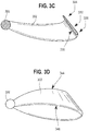
- FIG. 3A depicts a looped blade according to an illustrative example which is not part of the claimed invention.
- FIG. 3A depicts blade 302 attached to a central post 306 of a propeller according to an illustrative example which is not part of the claimed invention.
- the axis of rotation of blade 302 is coincident with the longitudinal axis of central post 306 in this example.
- Blade 302 has a top portion 308 and a bottom portion 310.
- the median line blade 302 is defined as the locus of points midway between the blade's leading edge 312 and its trailing edge 314 as shown by the broken line 316 running from the proximal end 318 to the distal end 320 of blade 302.
- the median line will not be continuous from top section through side portion to bottom portion.
- the median line of blade 302 is curved providing a curved appearance to the blade portions.
- blade portions may be cambered or otherwise curved, angular or flat, or a combination thereof.
- FIG. 5 depicts an embodiment wherein blade portions have substantially linear, and possibly non-continuous median lines.
- Air is compressed in the vicinity of central post 306 as the propeller spins.
- a gap 342 between bottom portion 310 and top portion 312 of blade 302 allows a larger volume of air to be compressed than if a gap did not exist. Air is caught on the inside surface of blade 302, thus pulling in air and creating the air flow from the sides as described above, while the outside surfaces of blade 302 function to push the air toward the back of the propeller.
- FIGS. 3B and 3C depict cross sections of blade 302 taken along lines 3B-3B and 3C-3C of FIG. 3A , respectively.
- Cross-section 3B-3B shows an airfoil shape comparable to a cross section of an airplane wing.
- surface 332 of blade 302 is curved, while the opposing surface 330 is substantially flat.
- the cross section of blade 302 is tapered laterally so that at a first area 334 it is thinner than at a second, opposing area 336, also comparable to an airplane wing.
- Other blade configurations are within the scope of the invention, as long as they fall within the scope of the appended claims, and will depend in part on the desired load on the propeller.
- blade 302 intersects central post 306 at a first blade intersection 338 and a second blade intersection 340.
- first and second blade intersections 338, 340 intersect central post 306, which can be at about the same angle ⁇ as measured counterclockwise from a line perpendicular to the longitudinal axis of central post 306, wherein the designated reference line appears as a "horizontal" line in FIG. 3B .
- An illustrative angle of intersection is about 25°, with an illustrative range being about 10° to about 35°.
- a further illustrative range of angles of intersection is about 15° to about 25°.
- intersection angle of the bottom portion of the blade with the central post is more extreme than the angle of intersection of the top portion of the blade with the central post.
- angles of intersection can be in the range of about 1° to about 89°.
- extreme it is meant more toward the vertical.
- An illustrative difference between the angle of intersection of the top portion of the blade as compared to the angle of intersection of the bottom portion of the blade is about 10°.
- An illustrative range is about 5 ° to about 20 ° and a further illustrative range is about 7 ° to about 15 °.
- the angle of intersection of the top portion of the blade is about 30 ° and the angle of intersection of the bottom portion of the blade is about 40 °. In a further illustrative example which is not part of the claimed invention, the angle of intersection of the top portion of the blade is about 75 ° and the angle of intersection of the bottom portion of the blade is about 85 °.
- Blade 302 as shown in FIGS. 3A-C exhibits a coarse blade angle, or pitch, near the axis of rotation with the pitch decreasing radially outward from the axis of rotation. Despite this downward gradient, the outermost point of the blade will still exhibit non-zero pitch.
- the blade may have a more course blade angle at the farthest point from the axis of rotation.
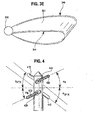
- FIGS. 3D and 3E depict blade 302 as viewed so central post 306 is perpendicular to the page.
- blade 302 would be rotating clockwise and has a leading edge 346 and a trailing edge 344.
- blade 302 would be rotating counterclockwise.
- the pitches of opposing blade intersections on either side of the axis of rotation differ from each other. So for example, in FIG. 4 you have a first blade 402 having a first blade intersection 404 at angle ⁇ A and a second blade intersection 406 at an angle ⁇ B , and an opposing blade would have a first blade intersection angle and a second blade intersection angle of ⁇ A ⁇ x and ⁇ B ⁇ x, respectively. So in other words, the pitch of opposing blade intersections differs.
- An illustrative difference in pitch between opposing blade intersections is about 50 °, wherein for example one blade intersection has a 25 ° pitch and the opposing blade has an intersection with a negative 25 ° pitch. Differences can be equally or unequally distribited. A general range of differences between the pitch of opposing blades is about 40° to about 60°. The pitch of opposing blade intersections are not equal from the plane of rotation as in the preceding example.
- FIG. 5 depicts an illustrative embodiment that includes two blades 502, 504 with substantially non-curved median lines.
- Median line 506 of top portion 508 and median line 510 of bottom portion 512 of blade 502 are substantially linear and are not parallel.
- Blade 504 also has a substantially linear median line.
- One or more substantially vertical wing segments 514, 516 connect top portion 508 and bottom portion 510 at intervals radiating from a central post 518 up to but not necessarily including the distal end 520 of blade 502.
- Blade 504 may have similar or the same vertical segments.
- the blades are flattened to an extent and would not necessarily be considered a "loop" with a continuous surface, the desired airflow may nonetheless be created with the addition of the wing segments, 514, 516, or both.
- wing segments 514, 516 pull air in from the sides toward central post 518, thus creating the desired airflow.
- top portion 1102 and bottom portion 1104 are not symmetrical. This can be accomplished, for example, by bottom portion 1104 being longer than the top portion 1102, with a side portion 1106 angled toward the front of the propeller to connect to the shorter top portion 1102. This can facilitate the airflow being pulled in from the side section to propel the blade forward. In general, a more extreme angle between the side portion and the top portion of the blade will result in more thrust and a higher forward rake for the top portion of the blade.
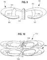
- FIGS. 6A and 6B show a propeller with three loop-shaped blades 602, 604, 606, according to an illustrative example which is not part of the claimed invention.
- FIG. 6A is a view of the propeller rotating so that counterclockwise rotation would cause airflow into the page
- FIG. 6B is a side view of the propeller.
- Blades 602, 604, 606 radiate from central post 608.
- Blades 602, 604, 606 are generally coplanar. Any number of loops can be combined to obtain the desired air flow. See for example FIGS. 7A , 7B with four blades and FIG. 8 with eight blades.
- Propellers can be "stacked” so they rotate in different planes. By “stacked” it is not meant that they necessarily abut one another.
- the stacked propellers can have gaps between them. They can be of uniform size or graduated from smaller to larger in a direction perpendicular to the plane of rotation from back to front, or larger to smaller in that direction.
- FIG. 10 shows an eight-loop propeller 1002 having a first plane of rotation stacked onto another eight-loop propeller 1004 having a second plane of rotation.
- the blades of propeller 1002 are attached to central post 1006, and the blades of propeller 1004 are attached to central post 1008.
- FIG. 10 illustrates two discrete central posts 1006 and 1008, propellers may also be stacked on a single central post.
- FIG. 12 depicts a further embodiment of a stacked propeller. Blades are disposed about a central post in a helix fashion.
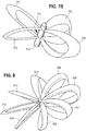
- FIGS. 7A and 7B depict a propeller having four blades 702, 704, 706, 708, according to an illustrative embodiment of the invention.
- Blades 702, 704, 706, 708 radiate from a central post 710 wherein of blades 702, 704, 706, 708 would generally spin in the same plane as the others.
- FIG.7A in this illustrative embodiment, there is a "gap" 712 between the attachment locations of a top portion of each blade and a bottom portion of each blade along central post 710, with which the axis of rotation is coincident.
- gap is used herein to describe the space around the axis of rotation between the center of the blade intersections with a central post created when a blade's top and bottom portion are attached at different longitudinal locations along a central post or axis of rotation.
- FIG. 3B depicts the location of the gap as shown by line 340.
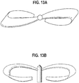
- the blade bottom portion may not be attached to the central post, such as shown in FIGS. 9 and 13A-B , in which case the gap is the distance between the center of the top blade portion intersection with the central post and the center of where the bottom blade portion would intersect the central post if it was extended to reach it.
- Propellers can be designed with various gap sizes.
- An illustrative gap size range is approximately about 2% to 55% of the length of a propeller's.
- Another illustrative gap size range is about 20% of a propeller's blade length to about 35% of a propeller's blade.
- a third illustrative gap size range is about 30% of a propeller's blade length to about 55% of a propeller's blade length.
- blades may be twisted, such as about the median line for example.
- a twist can be seen for example in FIG. 5 .
- Both top portion 508 and bottom portion 512 of blade 502 have an apparent twist.
- Curved blades can also be additionally twisted, such as can been seen in FIGS. 7A-B , or as would result from a difference in blade intersection angles ⁇ as shown in FIG. 4 .
- the propeller has a twist forming the curvature of the blades or relative curvature of opposing blades that is approximately 35 degrees.
- An illustrative range of twist is in the range of about 30 degrees to about 40 degrees. Other degrees of twisting are within the scope of the invention and can create various degrees and directions of airflow.
- FIG. 8 depicts an illustrative embodiment of the invention with eight "blades” 802, 804, 806, 808, 810, 812, 814, 816 made of four circles that are all slightly angled but have no half turn.
- At least the front edges of the loops are thin to cut through the air, but other edge shapes may be beneficial to achieve a desired air flow pattern.
- the specific shape, quantity and arrangement of the loops can be chosen to create a desired air flow pattern.
- FIG. 9 depicts a propeller having blades 902, 904 in loop form opposing one another wherein the bottom portions 906, 908 of blades 902, 904 are not attached to central post 910. Instead, "brace” 912 flexibly couples bottom portion 906 to top portion 914. Similarly, brace 916 flexibly couples bottom portion 908 to top portion 918.
- a "brace” as used herein is a blade component used to flexibly couple disparate blade portions.
- a brace can be made of steel, aluminum, composite materials such as carbon and fiber glass, or any other suitable blade material.
- Braces 912, 916 are angled with respect to the plane of rotation to pull air in toward the axis of rotation as the propeller rotates, thus creating drag.
- a brace may be angled in the same way as a blade's side portion to achieve the desired air flow. Further, the thickness, length, width, and other such characteristics of a brace are designed to achieve desired operation of a particular blade application, such as by way of an example, flight. Blades 902, 904 are disposed with respect to central post 910 in this manner to provide the flexibility of adjusting their pitches.
- the braces allow for the blades 902, 904 to be manipulated to change pitch during activities such as take-off, flight, or landing.
- the propeller can include an adjustment mechanism to allow selectable variations in the gap formed between top portions 914, 918 and bottom portions 906, 908 of the blades 902, 904, respectively.
- FIGS. 13A-B depict a top view and side view, respectively of a propeller with open-loop blades according to an illustrative example which does not form part of the claimed invention. This version does not include the braces as provided in FIG. 9 .
- Various embodiments of the propeller defined by the appended claims may be used in various devices, for example, the following illustrative devices: aircraft, watercraft, wind turbines, cooling devices, heating devices, automobile engines, and air circulation devices.
- Examples of method of manufacturing include a method of manufacturing an aforementioned propeller; a method of manufacturing a device comprising any of the aforementioned propellers; and a method of manufacturing a product wherein the method includes installing a device containing any of the aforementioned propellers.
Landscapes
- Engineering & Computer Science (AREA)
- Mechanical Engineering (AREA)
- Aviation & Aerospace Engineering (AREA)
- General Engineering & Computer Science (AREA)
- Chemical & Material Sciences (AREA)
- Combustion & Propulsion (AREA)
- Ocean & Marine Engineering (AREA)
- Physics & Mathematics (AREA)
- Fluid Mechanics (AREA)
- Structures Of Non-Positive Displacement Pumps (AREA)
- Wind Motors (AREA)
Priority Applications (1)
| Application Number | Priority Date | Filing Date | Title |
|---|---|---|---|
| PL18191741T PL3431387T3 (pl) | 2012-12-10 | 2013-12-09 | Śmigło |
Applications Claiming Priority (4)
| Application Number | Priority Date | Filing Date | Title |
|---|---|---|---|
| US201261735140P | 2012-12-10 | 2012-12-10 | |
| US13/843,344 US20140161622A1 (en) | 2012-12-10 | 2013-03-15 | Propeller |
| EP13875362.9A EP2941539B1 (en) | 2012-12-10 | 2013-12-09 | Propeller |
| PCT/US2013/073811 WO2014130134A2 (en) | 2012-12-10 | 2013-12-09 | Propeller |
Related Parent Applications (2)
| Application Number | Title | Priority Date | Filing Date |
|---|---|---|---|
| EP13875362.9A Division-Into EP2941539B1 (en) | 2012-12-10 | 2013-12-09 | Propeller |
| EP13875362.9A Division EP2941539B1 (en) | 2012-12-10 | 2013-12-09 | Propeller |
Publications (2)
| Publication Number | Publication Date |
|---|---|
| EP3431387A1 EP3431387A1 (en) | 2019-01-23 |
| EP3431387B1 true EP3431387B1 (en) | 2021-09-15 |
Family
ID=50881135
Family Applications (2)
| Application Number | Title | Priority Date | Filing Date |
|---|---|---|---|
| EP13875362.9A Active EP2941539B1 (en) | 2012-12-10 | 2013-12-09 | Propeller |
| EP18191741.0A Active EP3431387B1 (en) | 2012-12-10 | 2013-12-09 | Propeller |
Family Applications Before (1)
| Application Number | Title | Priority Date | Filing Date |
|---|---|---|---|
| EP13875362.9A Active EP2941539B1 (en) | 2012-12-10 | 2013-12-09 | Propeller |
Country Status (8)
| Country | Link |
|---|---|
| US (3) | US20140161622A1 (zh) |
| EP (2) | EP2941539B1 (zh) |
| JP (2) | JP6140296B2 (zh) |
| CN (2) | CN110667825B (zh) |
| DK (2) | DK2941539T3 (zh) |
| ES (2) | ES2706413T3 (zh) |
| PL (2) | PL3431387T3 (zh) |
| WO (1) | WO2014130134A2 (zh) |
Families Citing this family (19)
| Publication number | Priority date | Publication date | Assignee | Title |
|---|---|---|---|---|
| US20110274558A1 (en) * | 2010-05-10 | 2011-11-10 | Kathryn Chase | Modular windmill |
| US20140161622A1 (en) | 2012-12-10 | 2014-06-12 | Gregory Charles Sharrow | Propeller |
| US9926058B2 (en) * | 2012-12-10 | 2018-03-27 | Sharrow Engineering Llc | Propeller |
| US10232933B2 (en) * | 2015-12-17 | 2019-03-19 | Amazon Technologies, Inc. | Redundant aircraft propulsion system using co-rotating propellers joined by tip connectors |
| US10086933B2 (en) * | 2015-12-17 | 2018-10-02 | Amazon Technologies, Inc. | Redundant aircraft propulsion system using multiple motors per drive shaft |
| KR102143022B1 (ko) * | 2016-05-27 | 2020-08-11 | 섀로우 엔지니어링 엘엘씨 | 프로펠러 |
| CN106142681A (zh) * | 2016-09-29 | 2016-11-23 | 河北大艾智能科技股份有限公司 | 空心螺旋桨及其制造方法 |
| USD987545S1 (en) | 2017-05-25 | 2023-05-30 | Sharrow Engineering Llc | Propeller |
| US10836466B2 (en) | 2017-11-06 | 2020-11-17 | Massachusetts Institute Of Technology | Toroidal propeller |
| JP6979205B2 (ja) * | 2018-02-08 | 2021-12-08 | 国立研究開発法人宇宙航空研究開発機構 | プロペラ、プロペラの設計方法、プロペラ設計方法プログラム及び情報記憶媒体 |
| WO2019232535A1 (en) * | 2018-06-01 | 2019-12-05 | Joby Aero, Inc. | System and method for aircraft noise mitigation |
| WO2019234287A1 (en) * | 2018-06-06 | 2019-12-12 | Bondestam Marten | Rotor |
| WO2021045931A2 (en) | 2019-08-26 | 2021-03-11 | Massachusetts Institute Of Technology | Propeller design systems and methods |
| SE544385C2 (en) * | 2019-09-23 | 2022-05-03 | Volvo Penta Corp | Propeller combination for a marine vessel |
| CN112746933A (zh) * | 2021-01-16 | 2021-05-04 | 李颖 | 风力发电用风机机身快速连接装置及其使用方法 |
| USD1029041S1 (en) * | 2021-04-21 | 2024-05-28 | Sharrow Engineering Llc | Duo-propeller |
| KR20220058861A (ko) * | 2021-10-27 | 2022-05-10 | 박규리 | 발전용 선박 |
| CN114104266A (zh) * | 2021-12-17 | 2022-03-01 | 亿航智能设备(广州)有限公司 | 一种螺旋桨、动力组件和飞行器 |
| CN115195368A (zh) * | 2022-07-11 | 2022-10-18 | 中国船舶重工集团公司第七一九研究所 | 一种4d打印水陆两栖螺旋桨 |
Family Cites Families (28)
| Publication number | Priority date | Publication date | Assignee | Title |
|---|---|---|---|---|
| US467322A (en) * | 1892-01-19 | Screw propeller | ||
| US467323A (en) | 1892-01-19 | Screw propeller | ||
| US680671A (en) * | 1901-05-02 | 1901-08-13 | Myers Screw Propeller Syndicate Ltd | Screw-propeller. |
| US868220A (en) * | 1907-04-04 | 1907-10-15 | Julian Portelli | Propeller. |
| US917217A (en) * | 1908-11-05 | 1909-04-06 | Clinton H Weston | Propeller. |
| US1868113A (en) * | 1930-09-22 | 1932-07-19 | Spontan Ab | Fan |
| GB427493A (en) * | 1933-10-25 | 1935-04-25 | Unislip Propeller Company Ltd | Improvements in and relating to screw propellers |
| US2045383A (en) | 1934-04-11 | 1936-06-23 | Gen Regulator Corp | Propeller |
| US2273756A (en) * | 1939-10-18 | 1942-02-17 | Anemostat Corp | Fan |
| US2344266A (en) * | 1941-06-27 | 1944-03-14 | Reissner Hans | Aircraft propeller construction |
| US2473665A (en) | 1946-09-20 | 1949-06-21 | William W K Van Nort | Propeller |
| US3087553A (en) * | 1962-01-23 | 1963-04-30 | Paul M Kostyun | Counter rotating propeller drive |
| US3485462A (en) | 1967-08-28 | 1969-12-23 | Spence William | Aircraft propeller and jet drive |
| US5111576A (en) * | 1989-05-08 | 1992-05-12 | The United States Of America As Represented By The Secretary Of The Army | Method of making a flexprop |
| US5405246A (en) * | 1992-03-19 | 1995-04-11 | Goldberg; Steven B. | Vertical-axis wind turbine with a twisted blade configuration |
| RU2042414C1 (ru) * | 1992-04-28 | 1995-08-27 | Малое предприятие "Двойная Спираль-АвиаПолис" | Рабочий орган смесителя |
| US5890875A (en) * | 1997-01-27 | 1999-04-06 | Silvano; David | Blade apparatus |
| US6099256A (en) | 1997-01-27 | 2000-08-08 | Silvano; David | Three dimensional figure eight propeller/impeller blade apparatus |
| DE19931035A1 (de) * | 1999-07-06 | 2001-01-25 | Rudolf Bannasch | Rotor mit gespaltenem Rotorblatt |
| DE60139508D1 (de) * | 2001-01-26 | 2009-09-17 | Minoru Yoshida | Strömungsmaschine |
| US6948910B2 (en) * | 2002-07-12 | 2005-09-27 | Polacsek Ronald R | Spiral-based axial flow devices |
| CA2651931A1 (en) * | 2006-05-10 | 2007-11-22 | Viryd Technologies Inc. | Fluid energy converter |
| US20110299991A1 (en) * | 2008-09-26 | 2011-12-08 | Andrei Leonidovich Shpadi | Screw propeller (variants) and the involute of the blades thereof |
| US20120288374A1 (en) * | 2009-12-28 | 2012-11-15 | Volvo Aero Corporation | Air propeller arrangement and aircraft |
| KR101042200B1 (ko) | 2010-09-02 | 2011-06-16 | 드림스페이스월드주식회사 | Pcb를 사용한 무인 비행체 |
| US20140161622A1 (en) | 2012-12-10 | 2014-06-12 | Gregory Charles Sharrow | Propeller |
| CN104340348A (zh) | 2013-07-31 | 2015-02-11 | 应用热流分析中心股份有限公司 | 复合式螺桨扇叶构造 |
| RU2585180C1 (ru) | 2015-04-23 | 2016-05-27 | Федеральное Государственное Автономное Образовательное Учреждение Высшего Профессионального Образования "Дальневосточный Федеральный Университет" (Двфу) | Винт |
-
2013
- 2013-03-15 US US13/843,344 patent/US20140161622A1/en not_active Abandoned
- 2013-12-09 CN CN201910966949.XA patent/CN110667825B/zh active Active
- 2013-12-09 EP EP13875362.9A patent/EP2941539B1/en active Active
- 2013-12-09 CN CN201380063211.3A patent/CN104854310B/zh active Active
- 2013-12-09 JP JP2015547445A patent/JP6140296B2/ja active Active
- 2013-12-09 EP EP18191741.0A patent/EP3431387B1/en active Active
- 2013-12-09 ES ES13875362T patent/ES2706413T3/es active Active
- 2013-12-09 PL PL18191741T patent/PL3431387T3/pl unknown
- 2013-12-09 PL PL13875362T patent/PL2941539T3/pl unknown
- 2013-12-09 ES ES18191741T patent/ES2900554T3/es active Active
- 2013-12-09 DK DK13875362.9T patent/DK2941539T3/en active
- 2013-12-09 DK DK18191741.0T patent/DK3431387T3/da active
- 2013-12-09 WO PCT/US2013/073811 patent/WO2014130134A2/en active Application Filing
-
2016
- 2016-07-07 JP JP2016134830A patent/JP6140340B2/ja active Active
-
2017
- 2017-04-17 US US15/489,562 patent/US20170218772A1/en not_active Abandoned
-
2018
- 2018-04-18 US US15/956,303 patent/US11603184B2/en active Active
Also Published As
| Publication number | Publication date |
|---|---|
| CN110667825B (zh) | 2023-02-10 |
| CN104854310A (zh) | 2015-08-19 |
| WO2014130134A3 (en) | 2015-03-26 |
| PL3431387T3 (pl) | 2022-02-07 |
| CN110667825A (zh) | 2020-01-10 |
| WO2014130134A2 (en) | 2014-08-28 |
| JP2016507410A (ja) | 2016-03-10 |
| EP2941539B1 (en) | 2018-10-17 |
| JP2016222242A (ja) | 2016-12-28 |
| EP3431387A1 (en) | 2019-01-23 |
| DK3431387T3 (da) | 2021-11-22 |
| US20170218772A1 (en) | 2017-08-03 |
| US20180237122A1 (en) | 2018-08-23 |
| WO2014130134A9 (en) | 2015-05-14 |
| JP6140340B2 (ja) | 2017-05-31 |
| EP2941539A2 (en) | 2015-11-11 |
| EP2941539A4 (en) | 2016-09-07 |
| DK2941539T3 (en) | 2019-01-28 |
| US20140161622A1 (en) | 2014-06-12 |
| ES2706413T3 (es) | 2019-03-28 |
| JP6140296B2 (ja) | 2017-05-31 |
| US11603184B2 (en) | 2023-03-14 |
| PL2941539T3 (pl) | 2019-05-31 |
| CN104854310B (zh) | 2019-09-13 |
| ES2900554T3 (es) | 2022-03-17 |
Similar Documents
| Publication | Publication Date | Title |
|---|---|---|
| US11603184B2 (en) | Propeller | |
| US20220135195A1 (en) | Propeller | |
| JP5078883B2 (ja) | 高速回転翼航空機のロータブレード | |
| AU2017261498A1 (en) | Improved wing configuration | |
| AU2006322446B2 (en) | Blade for a wind turbine rotor | |
| AU2019203301B2 (en) | Propeller | |
| US7972114B2 (en) | Composite blade root structure | |
| WO2008088392A2 (en) | Rotor blade twist distribution for a high speed rotary-wing aircraft | |
| CN104153950B (zh) | 一种带有叶尖扰流结构的兆瓦级风力发电机叶片及其成型方法 | |
| US10815963B2 (en) | Wind-turbine rotor blade, trailing edge for wind-turbine rotor blade tip, method for producing a wind-turbine rotor blade, and wind turbine | |
| EP2604516B1 (en) | Minimally intrusive wingtip vortex wake mitigation using microvane arrays | |
| EP2883791B1 (en) | Helicopter with a Tail shroud | |
| US20190248472A1 (en) | Propeller assembly | |
| EP3078848B1 (en) | Load compensating devices | |
| US11999466B2 (en) | Ultra-wide-chord propeller | |
| US11396367B2 (en) | Vortex reduction apparatus for use with airfoils | |
| WO2021092677A1 (en) | Ultra-wide-chord propeller |
Legal Events
| Date | Code | Title | Description |
|---|---|---|---|
| PUAI | Public reference made under article 153(3) epc to a published international application that has entered the european phase |
Free format text: ORIGINAL CODE: 0009012 |
|
| STAA | Information on the status of an ep patent application or granted ep patent |
Free format text: STATUS: THE APPLICATION HAS BEEN PUBLISHED |
|
| AC | Divisional application: reference to earlier application |
Ref document number: 2941539 Country of ref document: EP Kind code of ref document: P |
|
| AK | Designated contracting states |
Kind code of ref document: A1 Designated state(s): AL AT BE BG CH CY CZ DE DK EE ES FI FR GB GR HR HU IE IS IT LI LT LU LV MC MK MT NL NO PL PT RO RS SE SI SK SM TR |
|
| STAA | Information on the status of an ep patent application or granted ep patent |
Free format text: STATUS: REQUEST FOR EXAMINATION WAS MADE |
|
| RAP1 | Party data changed (applicant data changed or rights of an application transferred) |
Owner name: SHARROW ENGINEERING LLC |
|
| 17P | Request for examination filed |
Effective date: 20190723 |
|
| RBV | Designated contracting states (corrected) |
Designated state(s): AL AT BE BG CH CY CZ DE DK EE ES FI FR GB GR HR HU IE IS IT LI LT LU LV MC MK MT NL NO PL PT RO RS SE SI SK SM TR |
|
| GRAP | Despatch of communication of intention to grant a patent |
Free format text: ORIGINAL CODE: EPIDOSNIGR1 |
|
| STAA | Information on the status of an ep patent application or granted ep patent |
Free format text: STATUS: GRANT OF PATENT IS INTENDED |
|
| INTG | Intention to grant announced |
Effective date: 20210421 |
|
| RIN1 | Information on inventor provided before grant (corrected) |
Inventor name: SHARROW, GREGORY CHARLES |
|
| GRAS | Grant fee paid |
Free format text: ORIGINAL CODE: EPIDOSNIGR3 |
|
| GRAA | (expected) grant |
Free format text: ORIGINAL CODE: 0009210 |
|
| STAA | Information on the status of an ep patent application or granted ep patent |
Free format text: STATUS: THE PATENT HAS BEEN GRANTED |
|
| RAP3 | Party data changed (applicant data changed or rights of an application transferred) |
Owner name: SHARROW ENGINEERING LLC |
|
| RIN1 | Information on inventor provided before grant (corrected) |
Inventor name: SHARROW, GREGORY CHARLES |
|
| AC | Divisional application: reference to earlier application |
Ref document number: 2941539 Country of ref document: EP Kind code of ref document: P |
|
| AK | Designated contracting states |
Kind code of ref document: B1 Designated state(s): AL AT BE BG CH CY CZ DE DK EE ES FI FR GB GR HR HU IE IS IT LI LT LU LV MC MK MT NL NO PL PT RO RS SE SI SK SM TR |
|
| REG | Reference to a national code |
Ref country code: CH Ref legal event code: EP |
|
| REG | Reference to a national code |
Ref country code: DE Ref legal event code: R096 Ref document number: 602013079308 Country of ref document: DE |
|
| REG | Reference to a national code |
Ref country code: IE Ref legal event code: FG4D |
|
| REG | Reference to a national code |
Ref country code: AT Ref legal event code: REF Ref document number: 1430334 Country of ref document: AT Kind code of ref document: T Effective date: 20211015 |
|
| REG | Reference to a national code |
Ref country code: DK Ref legal event code: T3 Effective date: 20211119 |
|
| REG | Reference to a national code |
Ref country code: FI Ref legal event code: FGE |
|
| REG | Reference to a national code |
Ref country code: SE Ref legal event code: TRGR |
|
| REG | Reference to a national code |
Ref country code: LT Ref legal event code: MG9D |
|
| REG | Reference to a national code |
Ref country code: NL Ref legal event code: FP |
|
| PG25 | Lapsed in a contracting state [announced via postgrant information from national office to epo] |
Ref country code: RS Free format text: LAPSE BECAUSE OF FAILURE TO SUBMIT A TRANSLATION OF THE DESCRIPTION OR TO PAY THE FEE WITHIN THE PRESCRIBED TIME-LIMIT Effective date: 20210915 Ref country code: HR Free format text: LAPSE BECAUSE OF FAILURE TO SUBMIT A TRANSLATION OF THE DESCRIPTION OR TO PAY THE FEE WITHIN THE PRESCRIBED TIME-LIMIT Effective date: 20210915 Ref country code: BG Free format text: LAPSE BECAUSE OF FAILURE TO SUBMIT A TRANSLATION OF THE DESCRIPTION OR TO PAY THE FEE WITHIN THE PRESCRIBED TIME-LIMIT Effective date: 20211215 Ref country code: LT Free format text: LAPSE BECAUSE OF FAILURE TO SUBMIT A TRANSLATION OF THE DESCRIPTION OR TO PAY THE FEE WITHIN THE PRESCRIBED TIME-LIMIT Effective date: 20210915 |
|
| REG | Reference to a national code |
Ref country code: GR Ref legal event code: EP Ref document number: 20210403279 Country of ref document: GR Effective date: 20220113 |
|
| REG | Reference to a national code |
Ref country code: AT Ref legal event code: MK05 Ref document number: 1430334 Country of ref document: AT Kind code of ref document: T Effective date: 20210915 |
|
| REG | Reference to a national code |
Ref country code: NO Ref legal event code: T2 Effective date: 20210915 |
|
| PG25 | Lapsed in a contracting state [announced via postgrant information from national office to epo] |
Ref country code: LV Free format text: LAPSE BECAUSE OF FAILURE TO SUBMIT A TRANSLATION OF THE DESCRIPTION OR TO PAY THE FEE WITHIN THE PRESCRIBED TIME-LIMIT Effective date: 20210915 |
|
| REG | Reference to a national code |
Ref country code: ES Ref legal event code: FG2A Ref document number: 2900554 Country of ref document: ES Kind code of ref document: T3 Effective date: 20220317 |
|
| PG25 | Lapsed in a contracting state [announced via postgrant information from national office to epo] |
Ref country code: AT Free format text: LAPSE BECAUSE OF FAILURE TO SUBMIT A TRANSLATION OF THE DESCRIPTION OR TO PAY THE FEE WITHIN THE PRESCRIBED TIME-LIMIT Effective date: 20210915 |
|
| PG25 | Lapsed in a contracting state [announced via postgrant information from national office to epo] |
Ref country code: IS Free format text: LAPSE BECAUSE OF FAILURE TO SUBMIT A TRANSLATION OF THE DESCRIPTION OR TO PAY THE FEE WITHIN THE PRESCRIBED TIME-LIMIT Effective date: 20220115 Ref country code: SM Free format text: LAPSE BECAUSE OF FAILURE TO SUBMIT A TRANSLATION OF THE DESCRIPTION OR TO PAY THE FEE WITHIN THE PRESCRIBED TIME-LIMIT Effective date: 20210915 Ref country code: SK Free format text: LAPSE BECAUSE OF FAILURE TO SUBMIT A TRANSLATION OF THE DESCRIPTION OR TO PAY THE FEE WITHIN THE PRESCRIBED TIME-LIMIT Effective date: 20210915 Ref country code: RO Free format text: LAPSE BECAUSE OF FAILURE TO SUBMIT A TRANSLATION OF THE DESCRIPTION OR TO PAY THE FEE WITHIN THE PRESCRIBED TIME-LIMIT Effective date: 20210915 Ref country code: PT Free format text: LAPSE BECAUSE OF FAILURE TO SUBMIT A TRANSLATION OF THE DESCRIPTION OR TO PAY THE FEE WITHIN THE PRESCRIBED TIME-LIMIT Effective date: 20220117 Ref country code: EE Free format text: LAPSE BECAUSE OF FAILURE TO SUBMIT A TRANSLATION OF THE DESCRIPTION OR TO PAY THE FEE WITHIN THE PRESCRIBED TIME-LIMIT Effective date: 20210915 Ref country code: CZ Free format text: LAPSE BECAUSE OF FAILURE TO SUBMIT A TRANSLATION OF THE DESCRIPTION OR TO PAY THE FEE WITHIN THE PRESCRIBED TIME-LIMIT Effective date: 20210915 Ref country code: AL Free format text: LAPSE BECAUSE OF FAILURE TO SUBMIT A TRANSLATION OF THE DESCRIPTION OR TO PAY THE FEE WITHIN THE PRESCRIBED TIME-LIMIT Effective date: 20210915 |
|
| REG | Reference to a national code |
Ref country code: DE Ref legal event code: R097 Ref document number: 602013079308 Country of ref document: DE |
|
| PLBE | No opposition filed within time limit |
Free format text: ORIGINAL CODE: 0009261 |
|
| STAA | Information on the status of an ep patent application or granted ep patent |
Free format text: STATUS: NO OPPOSITION FILED WITHIN TIME LIMIT |
|
| PG25 | Lapsed in a contracting state [announced via postgrant information from national office to epo] |
Ref country code: MC Free format text: LAPSE BECAUSE OF FAILURE TO SUBMIT A TRANSLATION OF THE DESCRIPTION OR TO PAY THE FEE WITHIN THE PRESCRIBED TIME-LIMIT Effective date: 20210915 |
|
| 26N | No opposition filed |
Effective date: 20220616 |
|
| PG25 | Lapsed in a contracting state [announced via postgrant information from national office to epo] |
Ref country code: SI Free format text: LAPSE BECAUSE OF FAILURE TO SUBMIT A TRANSLATION OF THE DESCRIPTION OR TO PAY THE FEE WITHIN THE PRESCRIBED TIME-LIMIT Effective date: 20210915 |
|
| REG | Reference to a national code |
Ref country code: BE Ref legal event code: MM Effective date: 20211231 |
|
| PG25 | Lapsed in a contracting state [announced via postgrant information from national office to epo] |
Ref country code: LU Free format text: LAPSE BECAUSE OF NON-PAYMENT OF DUE FEES Effective date: 20211209 Ref country code: IE Free format text: LAPSE BECAUSE OF NON-PAYMENT OF DUE FEES Effective date: 20211209 |
|
| PG25 | Lapsed in a contracting state [announced via postgrant information from national office to epo] |
Ref country code: BE Free format text: LAPSE BECAUSE OF NON-PAYMENT OF DUE FEES Effective date: 20211231 |
|
| PGFP | Annual fee paid to national office [announced via postgrant information from national office to epo] |
Ref country code: TR Payment date: 20221207 Year of fee payment: 10 |
|
| PG25 | Lapsed in a contracting state [announced via postgrant information from national office to epo] |
Ref country code: CY Free format text: LAPSE BECAUSE OF FAILURE TO SUBMIT A TRANSLATION OF THE DESCRIPTION OR TO PAY THE FEE WITHIN THE PRESCRIBED TIME-LIMIT Effective date: 20210915 |
|
| PG25 | Lapsed in a contracting state [announced via postgrant information from national office to epo] |
Ref country code: HU Free format text: LAPSE BECAUSE OF FAILURE TO SUBMIT A TRANSLATION OF THE DESCRIPTION OR TO PAY THE FEE WITHIN THE PRESCRIBED TIME-LIMIT; INVALID AB INITIO Effective date: 20131209 |
|
| PGFP | Annual fee paid to national office [announced via postgrant information from national office to epo] |
Ref country code: GR Payment date: 20231229 Year of fee payment: 11 Ref country code: GB Payment date: 20231227 Year of fee payment: 11 |
|
| PGFP | Annual fee paid to national office [announced via postgrant information from national office to epo] |
Ref country code: SE Payment date: 20231227 Year of fee payment: 11 Ref country code: NO Payment date: 20231227 Year of fee payment: 11 Ref country code: NL Payment date: 20231226 Year of fee payment: 11 Ref country code: IT Payment date: 20231220 Year of fee payment: 11 Ref country code: FR Payment date: 20231227 Year of fee payment: 11 Ref country code: FI Payment date: 20231227 Year of fee payment: 11 Ref country code: DK Payment date: 20231229 Year of fee payment: 11 |
|
| PGFP | Annual fee paid to national office [announced via postgrant information from national office to epo] |
Ref country code: PL Payment date: 20231220 Year of fee payment: 11 |
|
| PGFP | Annual fee paid to national office [announced via postgrant information from national office to epo] |
Ref country code: ES Payment date: 20240102 Year of fee payment: 11 |
|
| PG25 | Lapsed in a contracting state [announced via postgrant information from national office to epo] |
Ref country code: MK Free format text: LAPSE BECAUSE OF FAILURE TO SUBMIT A TRANSLATION OF THE DESCRIPTION OR TO PAY THE FEE WITHIN THE PRESCRIBED TIME-LIMIT Effective date: 20210915 |
|
| PGFP | Annual fee paid to national office [announced via postgrant information from national office to epo] |
Ref country code: DE Payment date: 20231229 Year of fee payment: 11 Ref country code: CH Payment date: 20240101 Year of fee payment: 11 |