EP3431383A1 - Ship steering device - Google Patents
Ship steering device Download PDFInfo
- Publication number
- EP3431383A1 EP3431383A1 EP17766579.1A EP17766579A EP3431383A1 EP 3431383 A1 EP3431383 A1 EP 3431383A1 EP 17766579 A EP17766579 A EP 17766579A EP 3431383 A1 EP3431383 A1 EP 3431383A1
- Authority
- EP
- European Patent Office
- Prior art keywords
- fixed
- level
- ship
- accuracy level
- point
- Prior art date
- Legal status (The legal status is an assumption and is not a legal conclusion. Google has not performed a legal analysis and makes no representation as to the accuracy of the status listed.)
- Granted
Links
Images







Classifications
-
- G—PHYSICS
- G01—MEASURING; TESTING
- G01S—RADIO DIRECTION-FINDING; RADIO NAVIGATION; DETERMINING DISTANCE OR VELOCITY BY USE OF RADIO WAVES; LOCATING OR PRESENCE-DETECTING BY USE OF THE REFLECTION OR RERADIATION OF RADIO WAVES; ANALOGOUS ARRANGEMENTS USING OTHER WAVES
- G01S19/00—Satellite radio beacon positioning systems; Determining position, velocity or attitude using signals transmitted by such systems
- G01S19/01—Satellite radio beacon positioning systems transmitting time-stamped messages, e.g. GPS [Global Positioning System], GLONASS [Global Orbiting Navigation Satellite System] or GALILEO
- G01S19/13—Receivers
- G01S19/14—Receivers specially adapted for specific applications
-
- B—PERFORMING OPERATIONS; TRANSPORTING
- B63—SHIPS OR OTHER WATERBORNE VESSELS; RELATED EQUIPMENT
- B63H—MARINE PROPULSION OR STEERING
- B63H25/00—Steering; Slowing-down otherwise than by use of propulsive elements; Dynamic anchoring, i.e. positioning vessels by means of main or auxiliary propulsive elements
- B63H25/02—Initiating means for steering, for slowing down, otherwise than by use of propulsive elements, or for dynamic anchoring
- B63H25/04—Initiating means for steering, for slowing down, otherwise than by use of propulsive elements, or for dynamic anchoring automatic, e.g. reacting to compass
-
- B—PERFORMING OPERATIONS; TRANSPORTING
- B63—SHIPS OR OTHER WATERBORNE VESSELS; RELATED EQUIPMENT
- B63H—MARINE PROPULSION OR STEERING
- B63H25/00—Steering; Slowing-down otherwise than by use of propulsive elements; Dynamic anchoring, i.e. positioning vessels by means of main or auxiliary propulsive elements
- B63H25/42—Steering or dynamic anchoring by propulsive elements; Steering or dynamic anchoring by propellers used therefor only; Steering or dynamic anchoring by rudders carrying propellers
-
- G—PHYSICS
- G01—MEASURING; TESTING
- G01S—RADIO DIRECTION-FINDING; RADIO NAVIGATION; DETERMINING DISTANCE OR VELOCITY BY USE OF RADIO WAVES; LOCATING OR PRESENCE-DETECTING BY USE OF THE REFLECTION OR RERADIATION OF RADIO WAVES; ANALOGOUS ARRANGEMENTS USING OTHER WAVES
- G01S19/00—Satellite radio beacon positioning systems; Determining position, velocity or attitude using signals transmitted by such systems
- G01S19/38—Determining a navigation solution using signals transmitted by a satellite radio beacon positioning system
- G01S19/39—Determining a navigation solution using signals transmitted by a satellite radio beacon positioning system the satellite radio beacon positioning system transmitting time-stamped messages, e.g. GPS [Global Positioning System], GLONASS [Global Orbiting Navigation Satellite System] or GALILEO
- G01S19/396—Determining accuracy or reliability of position or pseudorange measurements
-
- G—PHYSICS
- G01—MEASURING; TESTING
- G01S—RADIO DIRECTION-FINDING; RADIO NAVIGATION; DETERMINING DISTANCE OR VELOCITY BY USE OF RADIO WAVES; LOCATING OR PRESENCE-DETECTING BY USE OF THE REFLECTION OR RERADIATION OF RADIO WAVES; ANALOGOUS ARRANGEMENTS USING OTHER WAVES
- G01S19/00—Satellite radio beacon positioning systems; Determining position, velocity or attitude using signals transmitted by such systems
- G01S19/38—Determining a navigation solution using signals transmitted by a satellite radio beacon positioning system
- G01S19/39—Determining a navigation solution using signals transmitted by a satellite radio beacon positioning system the satellite radio beacon positioning system transmitting time-stamped messages, e.g. GPS [Global Positioning System], GLONASS [Global Orbiting Navigation Satellite System] or GALILEO
- G01S19/53—Determining attitude
-
- G—PHYSICS
- G05—CONTROLLING; REGULATING
- G05D—SYSTEMS FOR CONTROLLING OR REGULATING NON-ELECTRIC VARIABLES
- G05D1/00—Control of position, course, altitude or attitude of land, water, air or space vehicles, e.g. using automatic pilots
- G05D1/02—Control of position or course in two dimensions
- G05D1/0206—Control of position or course in two dimensions specially adapted to water vehicles
- G05D1/0208—Control of position or course in two dimensions specially adapted to water vehicles dynamic anchoring
-
- G—PHYSICS
- G08—SIGNALLING
- G08G—TRAFFIC CONTROL SYSTEMS
- G08G3/00—Traffic control systems for marine craft
-
- B—PERFORMING OPERATIONS; TRANSPORTING
- B63—SHIPS OR OTHER WATERBORNE VESSELS; RELATED EQUIPMENT
- B63H—MARINE PROPULSION OR STEERING
- B63H25/00—Steering; Slowing-down otherwise than by use of propulsive elements; Dynamic anchoring, i.e. positioning vessels by means of main or auxiliary propulsive elements
- B63H25/02—Initiating means for steering, for slowing down, otherwise than by use of propulsive elements, or for dynamic anchoring
- B63H25/04—Initiating means for steering, for slowing down, otherwise than by use of propulsive elements, or for dynamic anchoring automatic, e.g. reacting to compass
- B63H2025/045—Initiating means for steering, for slowing down, otherwise than by use of propulsive elements, or for dynamic anchoring automatic, e.g. reacting to compass making use of satellite radio beacon positioning systems, e.g. the Global Positioning System [GPS]
Definitions
- the present invention relates to a ship handling device for performing dynamic positioning control for use in ships and the like.
- GPS global positioning system
- a controller drives an actuator to maintain the ship body at a fixed point.
- a deviation may sometimes occur between a target position (position command value) in the dynamic positioning control and a measured position of the ship.
- a deviation may potentially occur between an absolute position (a position uniquely defined on the earth) of the ship body and a measured position of the ship body obtained by the satellite positioning system.
- some aspects of the present invention have an object to provide a ship handling device capable of performing dynamic positioning control with which an accuracy in maintaining a ship at a fixed point (i.e., a fixed-point maintaining accuracy), including a measurement accuracy of a satellite positioning system, can be assessed.
- a ship handling device is a ship handling device for performing dynamic positioning control for maintaining a ship body at a target position with use of a satellite positioning system, wherein a positioning accuracy level of the satellite positioning system is calculated based on a radio-wave reception state of the satellite positioning system, a fixed-point deviation amount level is calculated based on a fixed-point deviation amount calculated from the target position and a measured position measured by the satellite positioning system, and a fixed-point maintaining accuracy level indicative of an assumed range of an absolute position of the ship body relative to the target position is determined with reference to the positioning accuracy level and the fixed-point deviation amount level.
- the ship handling device is preferably configured such that the positioning accuracy level and the fixed-point deviation amount level are compared to each other such that in a case where the positioning accuracy level is lower than the fixed-point deviation amount level, the positioning accuracy level is determined as the fixed-point maintaining accuracy level, in a case where the fixed-point deviation amount level is lower than the positioning accuracy level, the fixed-point deviation amount level is determined as the fixed-point maintaining accuracy level, and in a case where the positioning accuracy level and the fixed-point deviation amount level are equal to each other, the positioning accuracy level and the fixed-point deviation amount level are determined as the fixed-point maintaining accuracy level.
- the ship handling device preferably further includes a notification means for notifying an operator of the fixed-point maintaining accuracy level.
- the ship handling device is preferably configured such that the radio-wave reception state of the satellite positioning system is determined based on an elapsed time after power-on of the satellite positioning system, a dilution of precision observed at the time of determination of a position in a horizontal plane and is received from the satellite positioning system, and the number of effective satellites for the satellite positioning system.
- the ship handling device allows an operator to easily assess an assumed range of an absolute position of a ship body relative to a target position, thereby making the operator alert to the situation.
- the ship 100 illustrated in FIG. 1 is a so-called twin-screw ship.
- the number of propeller shafts is not limited to two, but may be any number as long as the number is two or more.
- a front-and-back direction and a left-and-right direction are defined with a bow direction of the ship 100 being defined as the front.
- the ship 100 is a stern drive ship provided with outdrive devices 5 configured to generate a thrust by propulsion propellers 5E rotated by driving power from engines 2.
- the ship 100 includes a ship body 1 provided with a propulsion device and the ship handling device 7.
- the propulsion device includes the engines 2, the outdrive devices 5, and ECUs 16.
- the ship handling device 7 includes an accelerator lever 8, a steering wheel 9, a joystick lever 10, a monitor 12, a global navigation satellite system (GNSS) device 13, a heading sensor (orientation sensor) 14, and a ship handling control device 15.
- the ship 100 is the stern drive ship provided with the outdrive devices 5.
- the ship 100 is not limited to this.
- the ship 100 may be a shaft ship or the like.
- Each of the outdrive devices 5 is mainly constituted by an input shaft 5A connected to an output shaft of a corresponding one of the engines 2, a switching clutch 5B, a propeller shaft 5D to which driving power is transmitted from the input shaft 5A via a drive shaft 5C, and a propulsion propeller 5E fixed to the propeller shaft 5D.
- the outdrive device 5 is interlocked and coupled to the engine 2 in a one-to-one relation.
- the number of outdrive devices 5 with respect to the engine 2 is not limited to the number defined in the present embodiment.
- the drive device is not limited to the outdrive device 5 of the present embodiment.
- a drive device in which a propeller is directly or indirectly driven by an engine may be employed.
- a drive device of pod drive type may be employed.
- Each of the two engines 2 generates driving power for rotating a corresponding one of the propulsion propellers 5E on the port side and the starboard side.
- One of the engines 2 is disposed in a rear portion of the port side of the ship body 1, and the other of the engines 2 is disposed in a rear portion of the starboard side of the ship body 1.
- Each of the two switching clutches 5B switches the driving power, transmitted from the output shaft of a corresponding one of the engines 2, between a forward rotation direction and a reverse rotation direction, and outputs the resulting driving power.
- Each of the switching clutches 5B has a forward bevel gear and a reverse bevel gear coupled to an inner drum including disc plates. The switching clutch 5B switches the rotational direction from one to another by selecting, among the disc plates, a disc plate onto which a pressure plate in an outer drum coupled to the input shaft 5A is pressed.
- Each of the two propulsion propellers 5E rotates to generate thrust power.
- Each of the propulsion propellers 5E is driven by the driving power transmitted thereto from a corresponding one of the engines 2.
- Multiple blades arranged around the propeller shaft 5D rotate in water in the periphery, so that thrust power is generated.
- Each of the outdrive devices 5 is supported by a gimbal housing 1A attached to a stern board (transom board) of the ship body 1.
- the outdrive device 5 is supported by the gimbal housing la such that a gimbal ring 26, which serves as a rotating fulcrum shaft of the outdrive device 5, is substantially vertical to a waterline WL.
- the gimbal ring 26 has an upper edge to which a steering arm 29 is attached, the steering arm 29 extending to the inside of the ship body 1.
- the steering arm 29 causes the outdrive device 5 to turn around the gimbal ring 26.
- the steering arm 29 is driven by a hydraulic actuator 27 that is configured to operate according to an operation made with the steering wheel 9 or the joystick lever 10.
- the hydraulic actuator 27 is driven by an electromagnetic proportional control valve 28 configured to switch a flow direction of a hydraulic oil according to an operation made with the steering wheel 9 or the joystick lever 10.
- the accelerator lever 8 included in the ship handling device 7 generates a signal for a rotation speed of the propulsion propeller 5E on the port side, a signal for a rotation speed of the propulsion propeller 5E on the starboard side, and signals for rotation directions of these propulsion propellers 5E.
- the accelerator lever 8 includes a lever for the propulsion propeller 5E on the port side and a lever for the propulsion propeller 5E on the starboard side. That is, the accelerator lever 8 is configured to independently generate a signal for the propulsion propeller 5E on the port side and a signal for the propulsion propeller 5E on the starboard side.
- the accelerator lever 8 is configured to be inclined at a desired angle in the front-and-rear direction of the ship 100.
- the accelerator lever 8 is configured to independently generate signals for rotation speeds of the engines 2 and signals for switching states of the switching clutches 5B corresponding to the engines 2, based on the operation direction and the operation amount.
- the accelerator lever 8 When the accelerator lever 8 is operated to be inclined forward, the accelerator lever 8 generates signals for the propulsion propellers 5E to generate a thrust for causing the ship 100 to move forward. Meanwhile, when the accelerator lever 8 is operated to be inclined rearward, the accelerator lever 8 generates signals for the propulsion propellers 5E to generate a thrust for causing the ship 100 to move backward.
- the steering wheel 9 included in the ship handling device 7 is used to change turning angles of the outdrive devices 5.
- the outdrive devices 5 are turned so that the bow of the ship 100 is directed rightward.
- the outdrive devices 5 are turned so that the bow of the ship 100 is directed leftward.
- the joystick lever 10 included in the ship handling device 7 generates a signal for causing the ship 100 to move in a desired direction.
- the joystick lever 10 can be inclined in a desired direction at a desired angle.
- the joystick lever 10 can be operated to turn about a lever axis at a desired angle.
- the joystick lever 10 is configured to generate signals for the engines 2 and the outdrive devices 5B, based on the operation mode and the operation amount. Specifically, when the joystick lever 10 is operated to be inclined in a desired direction, the joystick lever 10 generates signals for the propulsion propellers 5E on both sides to cause the ship 100 to move in a direction corresponding to the operation with a thrust corresponding to the amount of the operation. When the joystick lever 10 is operated to turn about the lever axis, the joystick lever 10 generates signals for the propulsion propellers 5E on both sides to cause the ship 100 to turn in a desired direction with a thrust corresponding to the operation amount.
- the joystick lever 10 is provided with a dynamic positioning control switch 10A for setting target coordinates for dynamic positioning control and a setting switch 10B for performing various settings such as calibration for lateral movement, oblique movement, and turning of the ship 100.
- the dynamic positioning control switch 10A generates a signal for starting the dynamic positioning control.
- the configurations of the various switches provided to the joystick lever 10 are not limited to those described above. Alternatively, for example, additional switches for changing the various settings may be provided to the joystick lever. Further alternatively, the various switches may be provided on the display or in the vicinity of the display.
- the GNSS device 13 which is a satellite positioning system included in the ship handling device 7, receives a positioning signal broadcasted from a positioning satellite, and measures (calculates) positional coordinates of the ship 100.
- the positioning satellite refers to a GNSS satellite that may be a GPS satellite and the like.
- the GNSS device 13 receives signals from a plurality of satellites, calculates positional coordinates of the ship 100, and outputs a latitude La (n) and a longitude Lo (n) representing the current position. That is, the GNSS device 13 calculates absolute values of the positional coordinates of the ship 100.
- the heading sensor 14 which is an orientation sensor included in the ship handling device 7, measures (calculates) a direction of the ship 100.
- the heading sensor 14 calculates an orientation of the bow of the ship 100 based on the Earth's magnetic field and/or GNSS. That is, the heading sensor 14 calculates an absolute orientation of the bow of the ship 100.
- the heading sensor 14 may be, e.g., a satellite compass (Registered Trademark) that calculates the orientation with use of the GNSS device 13.
- each of the ECUs 16 controls a corresponding one of the engines 2.
- various programs and data for controlling a corresponding one of the engines 2 are stored.
- the ECUs 16 are provided for their respective engines 2.
- Each of the ECUs 16 may have a configuration in which a CPU, a ROM, a RAM, an HDD and/or the like are connected to each other via a bus, or may have a configuration including a single-chip LSI and/or the like.
- Each of the ECUs 16 is connected to components of a corresponding one of the engines 2, such as a fuel adjustment valve of a fuel supply pump, a fuel injection valve, and various sensors (these components are not illustrated).
- the ECU 16 can control a supply amount of the fuel adjustment valve and opening/closing of the fuel injection valve, and also can obtain information detected by various sensors.
- the ship handling control device 15 included in the ship handling device 7 controls the engines 2 and the outdrive devices 5 based on signals detected by, e.g., the accelerator lever 8, the steering wheel 9, and the joystick lever 10.
- the ship handling control device 15 may be configured to be capable of performing so-called automatic navigation that enables automatic handling of the ship along a route calculated from the current position and the preset destination based on the information from the GNSS device 13.
- the ship handling control device 15 various programs and data for controlling the engines 2 and the outdrive device 5 are stored.
- the ship handling control device 15 may have a configuration in which a CPU, a ROM, a RAM, an HDD, and/or the like are connected to each other via a bus, or may have a configuration including a single-chip LSI and/or the like.
- the ship handling control device 15 is connected to the ECUs 16, and can obtain information indicative of states of the switching clutches 5B, information indicative of operation states of the engines 2, information indicative of rotation speeds of the engines 2 that the ECUs 16 obtain from various sensors, and various signals that the ECUs 16 obtain from various sensors.
- the ship handling control device 15 can transmit, to the switching clutches 5B, signals for changing (switching) clutch states.
- the ship handling control device 15 is connected to the electromagnetic proportional control valves 28 of the outdrive devices 5, and is capable of controlling the electromagnetic proportional control valves 28 according to signals from the steering wheel 9, the joystick lever 10, and the like.
- the ship handling control device 15 can transmit, to the ECUs 16, signals for controlling the fuel adjustment valves of the fuel supply pumps, the fuel injection valves, and other various devices of the engines 2.
- the ship handling control device 15 is connected to the accelerator lever 8 and the joystick lever 10, so that the ship handling control device 15 can obtain signals from the acceleration lever 8 and the joystick lever 10.
- the ship handling control device 15 is connected to the GNSS device 13 and the heading sensor 14, so that the ship handling control device 15 can obtain absolute coordinates and an absolute orientation of the ship 100.
- the ship handling control device 15 is connected to the monitor 12, so that a measured position of the ship 100 and/or a ship handling state achieved with the joystick lever 10 can be displayed.
- the ship handling device 7 including the ship handling control device 15 that executes the dynamic positioning control for maintaining the ship body 1 at a target position by use of the satellite positioning system.
- the ship handling control device 15 can calculate an external force acting on the ship 100 and a ship speed, based on the position information from the GNSS device 13 and the orientation information from the heading sensor 14. Then, the ship handling control device 15 further calculates a setting value regarding thrust power for achieving balance with the external force thus calculated, and controls the ECUs 16 so that thrust power represented by the setting value is outputted.
- the ship handling control device 15 is connected to the dynamic positioning control switch 10A.
- the ship handling control device 15 can recognize switchover of the dynamic positioning control switch 10A between on and off.
- the dynamic positioning control switch 10A is disposed at a location in the ship body 1 where the dynamic positioning control switch 10A is operable by an operator.
- the dynamic positioning control switch 10A may be an alternative one, e.g., the one displayed on the monitor 12 of touch panel type.
- the ship handling control device 15 calculates the positioning accuracy level 19 of the GNSS device 13 based on a reception state of radio waves by the GNSS device 13 (i.e., a radio-wave reception state of the GNSS device 13).
- the radio-wave reception state of the GNSS device 13 is defined by an elapsed time after power-on of the GNSS device 13, a dilution of precision (DOP) observed at the time of determination of a position in a horizontal plane and is received from the GNSS device 13, and the number of effective satellites for the GNSS device 13 (see FIG. 5(A) ).
- DOP dilution of precision
- the elapsed time after power-on of the GNSS device 13 refers to a period of time (T) that has elapsed after the GNSS device 13 was powered on.
- T period of time
- a threshold T1 regarding stable operation of the system of the GNSS device 13 is set. At the threshold T1 or higher, the system of the GNSS device 13 operates stably.
- the dilution of precision observed at the time of determination of a position in a horizontal plane and is received from the GNSS device 13 refers to a horizontal dilution of precision (HDOP).
- DOP is a concept representing a positioning accuracy of the GNSS device 13.
- DOP represents a dilution of precision in positioning performed by the GNSS device 13.
- DOP is affected by arrangement of the GNSS satellites.
- HDOP represents, among a geometrical dilution of precision (GDOP) representing a dilution of precision observed at the time of determination of a position in three dimensions, a component in a horizontal direction.
- GDOP geometrical dilution of precision
- the number of effective satellites for the GNSS device 13 refers to the number of satellites having an SNR value that is equal to or higher than a predetermined value.
- SNR refers to a ratio between a signal and a noise, that is, a signal-to-noise ratio. Namely, SNR represents an intensity of a signal from each satellite.
- the positioning accuracy level 19 of the GNSS device 13 is calculated based on the radio-wave reception state defined by the elapsed time after power-on of the GNSS device 13, the dilution of precision observed at the time of determination of a position in a horizontal plane and is received from the GNSS device 13, and the number of effective satellites for the GNSS device 13.
- the positioning accuracy level 19 is "high" (level 1).
- the positioning accuracy level 19 is "intermediate” (level 2).
- the positioning accuracy level 19 is "low” (level 3).
- the positioning accuracy level 19 is "deviation" (level 4). Note that, a relation between the values of ⁇ , ⁇ , and ⁇ is expressed by ⁇ ⁇ ⁇ ⁇ , and a relation between the values of S1, S2, and S3 is expressed by S1 > S2 > S3.
- the positioning accuracy level 19 refers to a degree of how far an absolute position Z (a position uniquely defined on the earth) of the ship 100 may potentially be away from a measured position X measured by the GNSS device 13.
- the positioning accuracy level 19 is set such that a positioning accuracy level 19 having a lower level represents a greater estimated distance from the measured position X to the absolute position Z.
- Concentric circles indicative of a degree of how far the absolute position Z is away from the measured position X are provided.
- a plurality of (in the present embodiment, three) concentric circles are provided so that the number of concentric circles corresponds to the number of the positioning accuracy levels 19.
- a concentric circle at the innermost position has a radius A
- a concentric circle at the middle position has a radius B
- a concentric circle at the outermost position has a radius C.
- the positioning accuracy level 19 is "high” (level 1)
- the absolute position Z of the ship 100 is estimated to be within the concentric circle at the innermost position.
- the positioning accuracy level 19 is "intermediate” (level 2)
- the absolute position Z of the ship 100 is estimated to be within the concentric circle at the middle position.
- the positioning accuracy level 19 is "low” (level 3)
- the absolute position Z of the ship 100 is estimated to be within the concentric circle at the outermost position.
- the positioning accuracy level 19 is "deviation” (level 4)
- the absolute position Z of the ship 100 cannot be estimated.
- the embodiment illustrated in FIG. 5(B) shows a state where the positioning accuracy level 19 is "intermediate”.
- a level 20 of an amount of deviation from a fixed point i.e., a fixed-point deviation amount level 20.
- the ship handling control device 15 calculates the fixed-point deviation amount level 20 based on an amount of deviation from a fixed point (i.e., a fixed-point deviation amount) that is measured by a measured position X measured by the GNSS device 13 and a target position Y that is set at the time of starting the dynamic positioning control (see FIG. 6(B) ).
- the fixed-point deviation amount refers to a distance (L) between the measured position X measured by the GNSS device 13 and the target position Y.
- the fixed-point deviation amount level 20 represents a degree (spacing degree) of how far the measured position X measured by the GNSS device 13 and the target position Y that is set at the time of starting the dynamic positioning control are away from each other.
- the fixed-point deviation amount level 20 is set such that a fixed-point deviation amount level 20 having a lower level represents a greater distance (fixed-point deviation amount) between the measured position X and the target position Y.
- Concentric circles centered on the target position Y that is set at the time of starting the dynamic positioning control are provided to indicate a spacing degree between the measured position X and the target position Y.
- a plurality of (in the present embodiment, two) concentric circles are provided so that the number of concentric circles corresponds to the number of the fixed-point deviation amount levels 20.
- a concentric circle at the inner side has a radius B, and a concentric circle at the outer side has a radius C.
- the fixed-point deviation amount level 20 is "high” (level 1) or “intermediate” (level 2), and the measured position X of the ship 100 is estimated to be within the concentric circle at the inner side.
- the fixed-point deviation amount level 20 is "low” (level 3), and the measured position X of the ship 100 is estimated to be within the concentric circle at the outer side.
- the fixed-point deviation amount level 20 is "deviation” (level 4), and thus the measured position X of the ship 100 cannot be estimated.
- a relation between the values of L1 and L2 is expressed by L1 ⁇ L2 (see FIG. 6(A) ).
- the embodiment illustrated in FIG. 6(B) shows a state where the fixed-point deviation amount level 20 is "low”.
- the fixed-point maintaining accuracy level 21 refers to a degree of how far the absolute position Z of the ship 100 may potentially be away from the target position Y.
- the positioning accuracy level 19 is "high". Therefore, the absolute position Z of the ship 100 is estimated to be within, among the concentric circles centered on the measured position X of the ship 100, the concentric circle at the innermost position.
- the shortest value N and the longest value F of the distance between the target position Y and the absolute position Z of the ship 100 is as illustrated in FIG. 7(A) .
- a difference between the shortest value N and the longest value F is 2A, which is equal to a diameter of, among the concentric circles indicative of the positioning accuracy level 19, the concentric circle at the innermost position.
- This difference between the shortest value N and the longest value F is smaller than that in the state illustrated in FIG. 7(B) .
- the positioning accuracy level 19 less affects the fixed-point maintaining accuracy level 21 than does the fixed-point deviation amount level 20. Therefore, by calculating the fixed-point maintaining accuracy level 21 mainly based on the fixed-point deviation amount level 20, it is possible to yield an approximate fixed-point maintaining accuracy level 21.
- the positioning accuracy level 19 is "low". Therefore, the absolute position Z of the ship 100 is estimated to be within, among the concentric circles centered on the measured position X of the ship 100, the concentric circle at the outermost position.
- the shortest value N of the distance between the target position Y and the absolute position Z of the ship 100 is 0, and the longest value F between the target position Y and the absolute position Z of the ship 100 is as illustrated in FIG. 7(B) . In this case, a difference between the shortest value N and the longest value F is greater than that of FIG. 7(A) .
- the positioning accuracy level 19 affects the fixed-point maintaining accuracy level 21 more greatly than does the fixed-point deviation amount level 20. Therefore, by calculating the fixed-point maintaining accuracy level 21 mainly based on the positioning accuracy level 19, it is possible to yield an approximate fixed-point maintaining accuracy level 21.
- the fixed-point maintaining accuracy level 21 is determined with reference to the positioning accuracy level 19 and the fixed-point deviation amount level 20.
- a lower one of the positioning accuracy level 19 and the fixed-point deviation amount level 20 that have been calculated is determined as the fixed-point maintaining accuracy level 21.
- both of these levels are determined as the fixed-point maintaining accuracy level 21.
- the positioning accuracy level 19 is “low” (level 3) and the fixed-point deviation amount level 20 is "high” (level 1) or “intermediate” (level 2)
- the level of the positioning accuracy level 19, which is lower than the fixed-point deviation amount level 20 is determined as the fixed-point maintaining accuracy level 21.
- the positioning accuracy level 19 and the fixed-point deviation amount level 20 are equal to each other, and thus both of the levels are determined as the fixed-point maintaining accuracy level 21.
- the level of the fixed-point deviation amount level 20, which is lower than the positioning accuracy level 19, is determined as the fixed-point maintaining accuracy level 21.
- the absolute position Z of the ship 100 is estimated to be within the concentric circle being centered on the target position Y and having the radius A.
- the fixed-point maintaining accuracy level 21 is "intermediate” (level 2)
- the absolute position Z of the ship 100 is estimated to be within the concentric circle being centered on the target position Y and having the radius B.
- the fixed-point maintaining accuracy level 21 is "low” (level 3)
- the absolute position Z of the ship 100 is estimated to be within the concentric circle being centered on the target position Y and having the radius C.
- the fixed-point maintaining accuracy level 21 is "deviation” (level 4)
- the absolute position Z of the ship 100 cannot be estimated.
- the fixed-point maintaining accuracy level 21 a lower one of the positioning accuracy level 19 and the fixed-point deviation amount level 20 that have been calculated is determined as the fixed-point maintaining accuracy level 21. Meanwhile, if the positioning accuracy level 19 and the fixed-point deviation amount level 20 are equal to each other, both of these levels are determined as the fixed-point maintaining accuracy level 21. Consequently, it is possible to easily calculate an assumed range of the absolute position Z of the ship 100 relative to the target position Y.
- the fixed-point maintaining accuracy level 21 may be calculated accurately based on the positioning accuracy level 19 and the fixed-point deviation amount level 20 having been weighted according to importance with respect to the fixed-point maintaining accuracy level 21.
- step S11 it is determined whether or not an instruction to start the dynamic positioning control has been given.
- the dynamic positioning control is started when the dynamic positioning control switch 10A is operated to be turned on. If the instruction to start the dynamic positioning control has been given, the process advances to step S12.
- the GNSS device 13 receives a signal from a satellite. The position and the orientation of the ship 100 on the sea measured at the time of turning-on of the dynamic positioning control switch 10A are set as a target position Y and a target orientation Ya, respectively.
- step S12 the dynamic positioning control is executed.
- the ECUs 16 are controlled so that a thrust given by the propulsion device is balanced with an external force including a wind force and a tidal force.
- the ship 100 can be automatically maintained at the setting position and the setting orientation on the sea.
- a positioning accuracy level 19 of the GNSS device 13 is calculated.
- the positioning accuracy level 19 of the GNSS device 13 is calculated based on a radio-wave reception state defined by an elapsed time after power-on of the GNSS device 13 (described above), a dilution of precision observed at the time of determination of a position in a horizontal plane and is received from the GNSS device 13 (described above), and the number of effective satellites for the satellite positioning system (described above).
- the process advances to step S14.
- step S14 a fixed-point deviation amount level 20 is calculated based on a fixed-point deviation amount calculated from a measured position X measured by the GNSS device 13 and the target position Y. Upon completion of the calculation of the fixed-point deviation amount level 20, the process advances to step S15.
- step S15 it is determined whether or not the positioning accuracy level 19 calculated is lower than the fixed-point deviation amount level 20. If it is determined that the positioning accuracy level 19 is lower than the fixed-point deviation amount level 20, the process advances to step S16. If it is determined that the positioning accuracy level 19 is not lower than the fixed-point deviation amount level 20, the process advances to step S17.
- step S16 a fixed-point maintaining accuracy level 21 is determined based on the positioning accuracy level 19. Upon determination of the fixed-point maintaining accuracy level 21, the process advances to step S20.
- step S17 it is determined whether or not the positioning accuracy level 19 is equal to the fixed-point deviation amount level 20. If it is determined that the positioning accuracy level 19 is equal to the fixed-point deviation amount level 20, the process advances to step S18. If it is determined that the positioning accuracy level 19 is not equal to the fixed-point deviation amount level 20, the process advances to step S19.
- step S18 the fixed-point maintaining accuracy level 21 is determined based on the positioning accuracy level 19 and the fixed-point deviation amount level 20. Upon determination of the fixed-point maintaining accuracy level 21, the process advances to step S20.
- step S19 the fixed-point maintaining accuracy level 21 is determined based on the fixed-point deviation amount level 20. Upon determination of the fixed-point maintaining accuracy level 21, the process advances to step S20.
- step S20 the fixed-point maintaining accuracy level 21 thus determined is notified by a notification means 22. After the notification, the process returns to the start.
- FIG. 9 illustrates examples of indication of the fixed-point maintaining accuracy level 21 on the monitor 12.
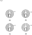
- the fixed-point maintaining accuracy level 21 is expressed by a plurality of (in the present embodiment, three) concentric circles whose number corresponds to the number of the fixed-point maintaining accuracy levels 21 with a ship body being displayed on the center of the concentric circles in a plan view and any of areas inside the concentric circles being indicated as one region with, e.g., a backlight. If the fixed-point maintaining accuracy level 21 is "high”, an area inside the concentric circle at the innermost position is indicated as one region. If the fixed-point maintaining accuracy level 21 is "intermediate", an area inside the concentric circle at the middle position is indicated as one region. Specifically, the area inside the concentric circle at the middle position, including the area inside the concentric circle at the innermost concentric circle, is indicated as one region.
- the fixed-point maintaining accuracy level 21 is "low" an area inside the concentric circle at the outermost position is indicated as one region. Specifically, the area inside the concentric circle at the outermost position, including the areas inside the concentric circles at the middle and innermost positions, is indicated as one region. If the fixed-point maintaining accuracy level 21 is "deviation", none of the concentric circles is indicated as one region.
- a speaker or the like may be used as the notification means 22, and a notification sound may be made thereby.
- a notification sound may be made thereby.
- the fixed-point maintaining accuracy level 21 is "deviation”
- notification of the fixed-point maintaining accuracy level 21 can be easily performed by making a notification sound.
- the monitor 12 and the speaker or the like are used as the notification means 22.
- the present invention is not limited to such a configuration. Also, the present invention is not limited to the above-described examples of indication of the fixed-point maintaining accuracy level 21.
- the fixed-point maintaining accuracy level 21 By displaying the fixed-point maintaining accuracy level 21 on the monitor 12 in the above-described manner, it is possible to easily notify the operator of an assumed range of the absolute position Z of the ship 100 relative to the target position Y. Consequently, for example, during the dynamic positioning control at a predetermined point, it is possible to make the operator alert to the situation and/or to allow the operator to predict a danger (e.g., the possibility of contact with an obstacle) according to the fixed-point maintaining accuracy level 21.
- a danger e.g., the possibility of contact with an obstacle
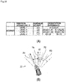
- the ship handling control device 15 can detect the orientation accuracy level 23 with reference to a measured orientation Xa of the ship 100 measured by the heading sensor 14.
- the orientation accuracy level 23 is detected based on an orientation difference R between the measured orientation Xa and a target orientation Ya that is set at the time of starting the dynamic positioning control (see FIG. 10(B) ).
- the orientation accuracy level 23 is set such that an orientation accuracy level 23 having a lower level represents a greater absolute value of an orientation difference R between a measured orientation Xa and a target orientation Ya.
- the orientation accuracy level 23 is "high". In a case where the orientation difference is expressed by -R2 ⁇ R ⁇ -R1 or R1 ⁇ R ⁇ R2, the orientation accuracy level 23 is "intermediate”. In a case where the orientation difference is expressed by -R3 ⁇ R ⁇ -R2 or R2 ⁇ R ⁇ R3, the orientation accuracy level 23 is "low”. In a case where the orientation difference is expressed by -R3 > R or R3 ⁇ R, the orientation accuracy level 23 is "deviation”. A relation between the values of R1, R2, and R3 is expressed by R1 ⁇ R2 ⁇ R3.
- the orientation accuracy level 23 can be indicated together with the fixed-point maintaining accuracy level 21.
- Lines are provided to extend radially from the center of the plurality of concentric circles displayed for the fixed-point maintaining accuracy level 21.
- the lines are provided to extend radially at angles R1, R2, and R3 relative to a longitudinal direction of the ship body in the concentric circles. These lines are indicated only in the outside of the concentric circle at the outermost position among the plurality of concentric circles.
- the orientation accuracy level 23 is expressed by indicating, as one region, any of areas between the lines extending at predetermined angles (angles of R1, R2, and R3).
- orientation accuracy level 23 in a case where the orientation accuracy level 23 is "high”, an area corresponding to an angle from -R1 to R1 is indicated as one region. In a case where the orientation accuracy level 23 is "intermediate”, an area corresponding to an angle from -R2 to R2 is indicated as one region. In a case where the orientation accuracy level 23 is "low”, an area corresponding to an angle from -R3 to R3 is indicated as one region. In a case where the orientation accuracy level 23 is "deviation", none of the areas is indicated as one region.
- the orientation accuracy level 23 By displaying the orientation accuracy level 23 on the monitor 12, it is possible to easily notify the operator of a deviation of the measured orientation Xa of the ship 100 from the target orientation Ya. Consequently, for example, especially in a case of large ships, during the dynamic positioning control at a predetermined point, it is possible to make the operator alert to the situation and/or to allow the operator to predict a danger (e.g., the possibility of contact with an obstacle) according to the orientation accuracy level 23.
- the present invention is not limited to the examples of indication of the orientation accuracy level 23.
- the present invention is applicable to a ship handling device.
Landscapes
- Engineering & Computer Science (AREA)
- Remote Sensing (AREA)
- Radar, Positioning & Navigation (AREA)
- General Physics & Mathematics (AREA)
- Physics & Mathematics (AREA)
- Ocean & Marine Engineering (AREA)
- Mechanical Engineering (AREA)
- Chemical & Material Sciences (AREA)
- Combustion & Propulsion (AREA)
- Computer Networks & Wireless Communication (AREA)
- Aviation & Aerospace Engineering (AREA)
- Automation & Control Theory (AREA)
- Position Fixing By Use Of Radio Waves (AREA)
- Navigation (AREA)
- Traffic Control Systems (AREA)
Abstract
Description
- The present invention relates to a ship handling device for performing dynamic positioning control for use in ships and the like.
- Heretofore, there has been disclosed a method for performing dynamic positioning control for a ship by which a ship body is controlled to be maintained at a fixed point through detection of a position of the ship body by, e.g., global positioning system (GPS) and monitoring of the position. According to the dynamic positioning control, based on a deviation between a position command value and a ship-body position signal from the GPS, a controller drives an actuator to maintain the ship body at a fixed point.
- PTL 1: Japanese Patent No.
3499204 - According to the above-described method for performing the dynamic positioning control for the ship, due to an external force, a deviation may sometimes occur between a target position (position command value) in the dynamic positioning control and a measured position of the ship. In addition, during the dynamic positioning control, depending on a measurement accuracy of a satellite positioning system such as GPS, a deviation may potentially occur between an absolute position (a position uniquely defined on the earth) of the ship body and a measured position of the ship body obtained by the satellite positioning system. In order to deal with this, some aspects of the present invention have an object to provide a ship handling device capable of performing dynamic positioning control with which an accuracy in maintaining a ship at a fixed point (i.e., a fixed-point maintaining accuracy), including a measurement accuracy of a satellite positioning system, can be assessed.
- A ship handling device according to an aspect of the present invention is a ship handling device for performing dynamic positioning control for maintaining a ship body at a target position with use of a satellite positioning system, wherein a positioning accuracy level of the satellite positioning system is calculated based on a radio-wave reception state of the satellite positioning system, a fixed-point deviation amount level is calculated based on a fixed-point deviation amount calculated from the target position and a measured position measured by the satellite positioning system, and a fixed-point maintaining accuracy level indicative of an assumed range of an absolute position of the ship body relative to the target position is determined with reference to the positioning accuracy level and the fixed-point deviation amount level.
- The ship handling device according to the aspect of the present invention is preferably configured such that the positioning accuracy level and the fixed-point deviation amount level are compared to each other such that in a case where the positioning accuracy level is lower than the fixed-point deviation amount level, the positioning accuracy level is determined as the fixed-point maintaining accuracy level, in a case where the fixed-point deviation amount level is lower than the positioning accuracy level, the fixed-point deviation amount level is determined as the fixed-point maintaining accuracy level, and in a case where the positioning accuracy level and the fixed-point deviation amount level are equal to each other, the positioning accuracy level and the fixed-point deviation amount level are determined as the fixed-point maintaining accuracy level.
- The ship handling device according to the aspect of the present invention preferably further includes a notification means for notifying an operator of the fixed-point maintaining accuracy level.
- The ship handling device according to the aspect of the present invention is preferably configured such that the radio-wave reception state of the satellite positioning system is determined based on an elapsed time after power-on of the satellite positioning system, a dilution of precision observed at the time of determination of a position in a horizontal plane and is received from the satellite positioning system, and the number of effective satellites for the satellite positioning system.
- The ship handling device according to the aspect of the present invention allows an operator to easily assess an assumed range of an absolute position of a ship body relative to a target position, thereby making the operator alert to the situation.
-
- [
FIG. 1 ] A view schematically illustrating an overview of an entire ship provided with a ship handling device. - [
FIG. 2 ] A view schematically illustrating arrangement of engines and outdrive devices of the ship provided with the ship handling device. - [
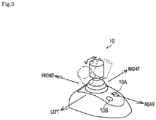
FIG. 3 ] A perspective view illustrating a configuration of a joystick lever of the ship handling device. - [
FIG. 4 ] A block diagram illustrating a control system related to the ship handling device. - [
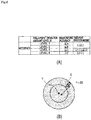
FIG. 5 ] (A) A table showing conditions of calculation of a positioning accuracy level. (B) A view schematically illustrating the positioning accuracy level. - [
FIG. 6 ] (A) A table showing conditions of calculation of a fixed-point deviation amount level. (B) A view schematically illustrating the fixed-point deviation amount level. - [
FIG. 7 ] (A) A view schematically illustrating an assumed range of an absolute position of the ship relative to a target position while the positioning accuracy level is "high" and the fixed-point deviation amount level is "low". (B) A view schematically illustrating an assumed range of an absolute position of the ship relative to a target position while the positioning accuracy level is "low" and the fixed-point deviation amount level is "high". - [
FIG. 8 ] A flowchart illustrating how a fixed-point maintaining accuracy level is determined in dynamic positioning control. - [
FIG. 9 ] (A) A view illustrating an example of indication of the fixed-point maintaining accuracy level that is "high". (B) A view illustrating an example of indication of the fixed-point maintaining accuracy level that is "intermediate". (C) A view illustrating an example of indication of the fixed-point maintaining accuracy level that is "low". (D) A view illustrating an example of indication of the fixed-point maintaining accuracy level that is "deviation". - [
FIG. 10 ] (A) A table showing conditions of calculation of an orientation accuracy level. (B) A view schematically illustrating the orientation accuracy level. - [
FIG. 11 ] (A) A view illustrating an example of indication of the orientation accuracy level that is "high". (B) A view illustrating an example of indication of the orientation accuracy level that is "intermediate". (C) A view illustrating an example of indication of the orientation accuracy level that is "low". (D) A view illustrating an example of indication of the orientation accuracy level that is "deviation". - First, with reference to
FIGs. 1 to 4 , an overview and a configuration of anentire ship 100 provided with aship handling device 7 will be described. Theship 100 illustrated inFIG. 1 is a so-called twin-screw ship. However, the number of propeller shafts is not limited to two, but may be any number as long as the number is two or more. In the present embodiment, a front-and-back direction and a left-and-right direction are defined with a bow direction of theship 100 being defined as the front. - As illustrated in
FIGs. 1 and2 , theship 100 is a stern drive ship provided withoutdrive devices 5 configured to generate a thrust bypropulsion propellers 5E rotated by driving power fromengines 2. Theship 100 includes aship body 1 provided with a propulsion device and theship handling device 7. The propulsion device includes theengines 2, theoutdrive devices 5, andECUs 16. Theship handling device 7 includes anaccelerator lever 8, asteering wheel 9, ajoystick lever 10, amonitor 12, a global navigation satellite system (GNSS)device 13, a heading sensor (orientation sensor) 14, and a shiphandling control device 15. In the present embodiment, theship 100 is the stern drive ship provided with theoutdrive devices 5. However, theship 100 is not limited to this. Alternatively, theship 100 may be a shaft ship or the like. - Each of the
outdrive devices 5 is mainly constituted by aninput shaft 5A connected to an output shaft of a corresponding one of theengines 2, a switching clutch 5B, apropeller shaft 5D to which driving power is transmitted from theinput shaft 5A via adrive shaft 5C, and apropulsion propeller 5E fixed to thepropeller shaft 5D. Theoutdrive device 5 is interlocked and coupled to theengine 2 in a one-to-one relation. Note that the number ofoutdrive devices 5 with respect to theengine 2 is not limited to the number defined in the present embodiment. Note also that the drive device is not limited to theoutdrive device 5 of the present embodiment. Alternatively, a drive device in which a propeller is directly or indirectly driven by an engine may be employed. Further alternatively, a drive device of pod drive type may be employed. - Each of the two
engines 2 generates driving power for rotating a corresponding one of thepropulsion propellers 5E on the port side and the starboard side. One of theengines 2 is disposed in a rear portion of the port side of theship body 1, and the other of theengines 2 is disposed in a rear portion of the starboard side of theship body 1. - Each of the two switching clutches 5B switches the driving power, transmitted from the output shaft of a corresponding one of the
engines 2, between a forward rotation direction and a reverse rotation direction, and outputs the resulting driving power. Each of the switching clutches 5B has a forward bevel gear and a reverse bevel gear coupled to an inner drum including disc plates. The switching clutch 5B switches the rotational direction from one to another by selecting, among the disc plates, a disc plate onto which a pressure plate in an outer drum coupled to theinput shaft 5A is pressed. - Each of the two
propulsion propellers 5E rotates to generate thrust power. Each of thepropulsion propellers 5E is driven by the driving power transmitted thereto from a corresponding one of theengines 2. Multiple blades arranged around thepropeller shaft 5D rotate in water in the periphery, so that thrust power is generated. - Each of the
outdrive devices 5 is supported by agimbal housing 1A attached to a stern board (transom board) of theship body 1. Specifically, theoutdrive device 5 is supported by the gimbal housing la such that agimbal ring 26, which serves as a rotating fulcrum shaft of theoutdrive device 5, is substantially vertical to a waterline WL. - The
gimbal ring 26 has an upper edge to which asteering arm 29 is attached, thesteering arm 29 extending to the inside of theship body 1. Thesteering arm 29 causes theoutdrive device 5 to turn around thegimbal ring 26. Thesteering arm 29 is driven by ahydraulic actuator 27 that is configured to operate according to an operation made with thesteering wheel 9 or thejoystick lever 10. Thehydraulic actuator 27 is driven by an electromagneticproportional control valve 28 configured to switch a flow direction of a hydraulic oil according to an operation made with thesteering wheel 9 or thejoystick lever 10. - The
accelerator lever 8 included in theship handling device 7 generates a signal for a rotation speed of thepropulsion propeller 5E on the port side, a signal for a rotation speed of thepropulsion propeller 5E on the starboard side, and signals for rotation directions of thesepropulsion propellers 5E. Theaccelerator lever 8 includes a lever for thepropulsion propeller 5E on the port side and a lever for thepropulsion propeller 5E on the starboard side. That is, theaccelerator lever 8 is configured to independently generate a signal for thepropulsion propeller 5E on the port side and a signal for thepropulsion propeller 5E on the starboard side. Theaccelerator lever 8 is configured to be inclined at a desired angle in the front-and-rear direction of theship 100. Theaccelerator lever 8 is configured to independently generate signals for rotation speeds of theengines 2 and signals for switching states of the switching clutches 5B corresponding to theengines 2, based on the operation direction and the operation amount. When theaccelerator lever 8 is operated to be inclined forward, theaccelerator lever 8 generates signals for thepropulsion propellers 5E to generate a thrust for causing theship 100 to move forward. Meanwhile, when theaccelerator lever 8 is operated to be inclined rearward, theaccelerator lever 8 generates signals for thepropulsion propellers 5E to generate a thrust for causing theship 100 to move backward. - The
steering wheel 9 included in theship handling device 7 is used to change turning angles of theoutdrive devices 5. When thesteering wheel 9 is turned rightward, theoutdrive devices 5 are turned so that the bow of theship 100 is directed rightward. Similarly, when thesteering wheel 9 is turned leftward, theoutdrive devices 5 are turned so that the bow of theship 100 is directed leftward. - As illustrated in
FIGs. 1 and3 , thejoystick lever 10 included in theship handling device 7 generates a signal for causing theship 100 to move in a desired direction. Thejoystick lever 10 can be inclined in a desired direction at a desired angle. Thejoystick lever 10 can be operated to turn about a lever axis at a desired angle. Thejoystick lever 10 is configured to generate signals for theengines 2 and the outdrive devices 5B, based on the operation mode and the operation amount. Specifically, when thejoystick lever 10 is operated to be inclined in a desired direction, thejoystick lever 10 generates signals for thepropulsion propellers 5E on both sides to cause theship 100 to move in a direction corresponding to the operation with a thrust corresponding to the amount of the operation. When thejoystick lever 10 is operated to turn about the lever axis, thejoystick lever 10 generates signals for thepropulsion propellers 5E on both sides to cause theship 100 to turn in a desired direction with a thrust corresponding to the operation amount. - The
joystick lever 10 is provided with a dynamicpositioning control switch 10A for setting target coordinates for dynamic positioning control and a settingswitch 10B for performing various settings such as calibration for lateral movement, oblique movement, and turning of theship 100. The dynamicpositioning control switch 10A generates a signal for starting the dynamic positioning control. The configurations of the various switches provided to thejoystick lever 10 are not limited to those described above. Alternatively, for example, additional switches for changing the various settings may be provided to the joystick lever. Further alternatively, the various switches may be provided on the display or in the vicinity of the display. - The
GNSS device 13, which is a satellite positioning system included in theship handling device 7, receives a positioning signal broadcasted from a positioning satellite, and measures (calculates) positional coordinates of theship 100. The positioning satellite refers to a GNSS satellite that may be a GPS satellite and the like. TheGNSS device 13 receives signals from a plurality of satellites, calculates positional coordinates of theship 100, and outputs a latitude La (n) and a longitude Lo (n) representing the current position. That is, theGNSS device 13 calculates absolute values of the positional coordinates of theship 100. - The heading
sensor 14, which is an orientation sensor included in theship handling device 7, measures (calculates) a direction of theship 100. The headingsensor 14 calculates an orientation of the bow of theship 100 based on the Earth's magnetic field and/or GNSS. That is, the headingsensor 14 calculates an absolute orientation of the bow of theship 100. The headingsensor 14 may be, e.g., a satellite compass (Registered Trademark) that calculates the orientation with use of theGNSS device 13. - As illustrated in
FIG. 1 , each of theECUs 16 controls a corresponding one of theengines 2. In each of theECUs 16, various programs and data for controlling a corresponding one of theengines 2 are stored. TheECUs 16 are provided for theirrespective engines 2. Each of theECUs 16 may have a configuration in which a CPU, a ROM, a RAM, an HDD and/or the like are connected to each other via a bus, or may have a configuration including a single-chip LSI and/or the like. - Each of the
ECUs 16 is connected to components of a corresponding one of theengines 2, such as a fuel adjustment valve of a fuel supply pump, a fuel injection valve, and various sensors (these components are not illustrated). Thus, theECU 16 can control a supply amount of the fuel adjustment valve and opening/closing of the fuel injection valve, and also can obtain information detected by various sensors. - The ship
handling control device 15 included in theship handling device 7 controls theengines 2 and theoutdrive devices 5 based on signals detected by, e.g., theaccelerator lever 8, thesteering wheel 9, and thejoystick lever 10. The shiphandling control device 15 may be configured to be capable of performing so-called automatic navigation that enables automatic handling of the ship along a route calculated from the current position and the preset destination based on the information from theGNSS device 13. - In the ship
handling control device 15, various programs and data for controlling theengines 2 and theoutdrive device 5 are stored. The shiphandling control device 15 may have a configuration in which a CPU, a ROM, a RAM, an HDD, and/or the like are connected to each other via a bus, or may have a configuration including a single-chip LSI and/or the like. - The ship
handling control device 15 is connected to theECUs 16, and can obtain information indicative of states of the switching clutches 5B, information indicative of operation states of theengines 2, information indicative of rotation speeds of theengines 2 that theECUs 16 obtain from various sensors, and various signals that theECUs 16 obtain from various sensors. - The ship
handling control device 15 can transmit, to the switching clutches 5B, signals for changing (switching) clutch states. - The ship
handling control device 15 is connected to the electromagneticproportional control valves 28 of theoutdrive devices 5, and is capable of controlling the electromagneticproportional control valves 28 according to signals from thesteering wheel 9, thejoystick lever 10, and the like. - The ship
handling control device 15 can transmit, to theECUs 16, signals for controlling the fuel adjustment valves of the fuel supply pumps, the fuel injection valves, and other various devices of theengines 2. - The ship
handling control device 15 is connected to theaccelerator lever 8 and thejoystick lever 10, so that the shiphandling control device 15 can obtain signals from theacceleration lever 8 and thejoystick lever 10. - The ship
handling control device 15 is connected to theGNSS device 13 and the headingsensor 14, so that the shiphandling control device 15 can obtain absolute coordinates and an absolute orientation of theship 100. - The ship
handling control device 15 is connected to themonitor 12, so that a measured position of theship 100 and/or a ship handling state achieved with thejoystick lever 10 can be displayed. - Next, with reference to
FIG. 4 , the following will describe a configuration of theship handling device 7 including the shiphandling control device 15 that executes the dynamic positioning control for maintaining theship body 1 at a target position by use of the satellite positioning system. - The ship
handling control device 15 can calculate an external force acting on theship 100 and a ship speed, based on the position information from theGNSS device 13 and the orientation information from the headingsensor 14. Then, the shiphandling control device 15 further calculates a setting value regarding thrust power for achieving balance with the external force thus calculated, and controls theECUs 16 so that thrust power represented by the setting value is outputted. - The ship
handling control device 15 is connected to the dynamicpositioning control switch 10A. The shiphandling control device 15 can recognize switchover of the dynamicpositioning control switch 10A between on and off. The dynamicpositioning control switch 10A is disposed at a location in theship body 1 where the dynamicpositioning control switch 10A is operable by an operator. Instead of the dynamicpositioning control switch 10A attached to thejoystick lever 10, the dynamicpositioning control switch 10A may be an alternative one, e.g., the one displayed on themonitor 12 of touch panel type. - With reference to
FIG. 5(A) , the following will describe apositioning accuracy level 19. - The ship
handling control device 15 calculates thepositioning accuracy level 19 of theGNSS device 13 based on a reception state of radio waves by the GNSS device 13 (i.e., a radio-wave reception state of the GNSS device 13). The radio-wave reception state of theGNSS device 13 is defined by an elapsed time after power-on of theGNSS device 13, a dilution of precision (DOP) observed at the time of determination of a position in a horizontal plane and is received from theGNSS device 13, and the number of effective satellites for the GNSS device 13 (seeFIG. 5(A) ). - The elapsed time after power-on of the
GNSS device 13 refers to a period of time (T) that has elapsed after theGNSS device 13 was powered on. For the elapsed time after power-on of theGNSS device 13, a threshold T1 regarding stable operation of the system of theGNSS device 13 is set. At the threshold T1 or higher, the system of theGNSS device 13 operates stably. - The dilution of precision observed at the time of determination of a position in a horizontal plane and is received from the
GNSS device 13 refers to a horizontal dilution of precision (HDOP). DOP is a concept representing a positioning accuracy of theGNSS device 13. DOP represents a dilution of precision in positioning performed by theGNSS device 13. DOP is affected by arrangement of the GNSS satellites. HDOP represents, among a geometrical dilution of precision (GDOP) representing a dilution of precision observed at the time of determination of a position in three dimensions, a component in a horizontal direction. - The number of effective satellites for the
GNSS device 13 refers to the number of satellites having an SNR value that is equal to or higher than a predetermined value. SNR refers to a ratio between a signal and a noise, that is, a signal-to-noise ratio. Namely, SNR represents an intensity of a signal from each satellite. - With the configuration described above, the
positioning accuracy level 19 of theGNSS device 13 is calculated based on the radio-wave reception state defined by the elapsed time after power-on of theGNSS device 13, the dilution of precision observed at the time of determination of a position in a horizontal plane and is received from theGNSS device 13, and the number of effective satellites for theGNSS device 13. - Specifically, in a case where the elapsed time after power-on is expressed by T ≥ T1, HDOP is ≤ α, and the number of effective satellites for the
GNSS device 13 is expressed by S ≥ S1, thepositioning accuracy level 19 is "high" (level 1). In a case where the elapsed time after power-on is expressed by T ≥ T1, HDOP is ≤ β, and the number of effective satellites for theGNSS device 13 is expressed by S ≥ S2, thepositioning accuracy level 19 is "intermediate" (level 2). In a case where the elapsed time after power-on is expressed by T ≥ T1, HDOP is ≤ γ, and the number of effective satellites for theGNSS device 13 is expressed by S ≥ S3, thepositioning accuracy level 19 is "low" (level 3). In a case where the elapsed time after power-on is expressed by T < T1, HDOP is > γ, or the number of effective satellites for theGNSS device 13 is expressed by S < S3, thepositioning accuracy level 19 is "deviation" (level 4). Note that, a relation between the values of α, β, and γ is expressed by α < β < γ, and a relation between the values of S1, S2, and S3 is expressed by S1 > S2 > S3. - With reference to
FIG. 5(B) , the following will further describe thepositioning accuracy level 19. - The
positioning accuracy level 19 refers to a degree of how far an absolute position Z (a position uniquely defined on the earth) of theship 100 may potentially be away from a measured position X measured by theGNSS device 13. Thepositioning accuracy level 19 is set such that apositioning accuracy level 19 having a lower level represents a greater estimated distance from the measured position X to the absolute position Z. - Concentric circles indicative of a degree of how far the absolute position Z is away from the measured position X are provided. A plurality of (in the present embodiment, three) concentric circles are provided so that the number of concentric circles corresponds to the number of the
positioning accuracy levels 19. A concentric circle at the innermost position has a radius A, a concentric circle at the middle position has a radius B, and a concentric circle at the outermost position has a radius C. - Specifically, in a case where the
positioning accuracy level 19 is "high" (level 1), the absolute position Z of theship 100 is estimated to be within the concentric circle at the innermost position. In a case where thepositioning accuracy level 19 is "intermediate" (level 2), the absolute position Z of theship 100 is estimated to be within the concentric circle at the middle position. In a case where thepositioning accuracy level 19 is "low" (level 3), the absolute position Z of theship 100 is estimated to be within the concentric circle at the outermost position. In a case where thepositioning accuracy level 19 is "deviation" (level 4), the absolute position Z of theship 100 cannot be estimated. The embodiment illustrated inFIG. 5(B) shows a state where thepositioning accuracy level 19 is "intermediate". - With reference to
FIG. 6 , the following will describe alevel 20 of an amount of deviation from a fixed point (i.e., a fixed-point deviation amount level 20). - The ship
handling control device 15 calculates the fixed-pointdeviation amount level 20 based on an amount of deviation from a fixed point (i.e., a fixed-point deviation amount) that is measured by a measured position X measured by theGNSS device 13 and a target position Y that is set at the time of starting the dynamic positioning control (seeFIG. 6(B) ). The fixed-point deviation amount refers to a distance (L) between the measured position X measured by theGNSS device 13 and the target position Y. - The fixed-point
deviation amount level 20 represents a degree (spacing degree) of how far the measured position X measured by theGNSS device 13 and the target position Y that is set at the time of starting the dynamic positioning control are away from each other. The fixed-pointdeviation amount level 20 is set such that a fixed-pointdeviation amount level 20 having a lower level represents a greater distance (fixed-point deviation amount) between the measured position X and the target position Y. - Concentric circles centered on the target position Y that is set at the time of starting the dynamic positioning control are provided to indicate a spacing degree between the measured position X and the target position Y. A plurality of (in the present embodiment, two) concentric circles are provided so that the number of concentric circles corresponds to the number of the fixed-point
deviation amount levels 20. A concentric circle at the inner side has a radius B, and a concentric circle at the outer side has a radius C. - Specifically, in a case where the fixed-point deviation amount is expressed by L ≤ L1, the fixed-point
deviation amount level 20 is "high" (level 1) or "intermediate" (level 2), and the measured position X of theship 100 is estimated to be within the concentric circle at the inner side. In a case where the fixed-point deviation amount is expressed by L1 < L ≤ L2, the fixed-pointdeviation amount level 20 is "low" (level 3), and the measured position X of theship 100 is estimated to be within the concentric circle at the outer side. In a case where the fixed-point deviation amount is expressed by L > L2, the fixed-pointdeviation amount level 20 is "deviation" (level 4), and thus the measured position X of theship 100 cannot be estimated. Note that a relation between the values of L1 and L2 is expressed by L1 < L2 (seeFIG. 6(A) ). The embodiment illustrated inFIG. 6(B) shows a state where the fixed-pointdeviation amount level 20 is "low". - With reference to
FIG. 7 , the following will describe a method for determining a fixed-point maintainingaccuracy level 21 indicative of an assumed range of an absolute position Z of theship 100 relative to a target position Y. The fixed-point maintainingaccuracy level 21 refers to a degree of how far the absolute position Z of theship 100 may potentially be away from the target position Y. - In
FIG. 7(A) , thepositioning accuracy level 19 is "high". Therefore, the absolute position Z of theship 100 is estimated to be within, among the concentric circles centered on the measured position X of theship 100, the concentric circle at the innermost position. The shortest value N and the longest value F of the distance between the target position Y and the absolute position Z of theship 100 is as illustrated inFIG. 7(A) . In this state, a difference between the shortest value N and the longest value F is 2A, which is equal to a diameter of, among the concentric circles indicative of thepositioning accuracy level 19, the concentric circle at the innermost position. This difference between the shortest value N and the longest value F is smaller than that in the state illustrated inFIG. 7(B) . Thus, thepositioning accuracy level 19 less affects the fixed-point maintainingaccuracy level 21 than does the fixed-pointdeviation amount level 20. Therefore, by calculating the fixed-point maintainingaccuracy level 21 mainly based on the fixed-pointdeviation amount level 20, it is possible to yield an approximate fixed-point maintainingaccuracy level 21. - In
FIG. 7(B) , thepositioning accuracy level 19 is "low". Therefore, the absolute position Z of theship 100 is estimated to be within, among the concentric circles centered on the measured position X of theship 100, the concentric circle at the outermost position. The shortest value N of the distance between the target position Y and the absolute position Z of theship 100 is 0, and the longest value F between the target position Y and the absolute position Z of theship 100 is as illustrated inFIG. 7(B) . In this case, a difference between the shortest value N and the longest value F is greater than that ofFIG. 7(A) . Thus, thepositioning accuracy level 19 affects the fixed-point maintainingaccuracy level 21 more greatly than does the fixed-pointdeviation amount level 20. Therefore, by calculating the fixed-point maintainingaccuracy level 21 mainly based on thepositioning accuracy level 19, it is possible to yield an approximate fixed-point maintainingaccuracy level 21. - With reference to
FIG. 8 , the following will further describe the method for determining a fixed-point maintainingaccuracy level 21 indicative of an assumed range of an absolute position Z of theship 100 relative to a target position Y. The fixed-point maintainingaccuracy level 21 is determined with reference to thepositioning accuracy level 19 and the fixed-pointdeviation amount level 20. In the present embodiment, a lower one of thepositioning accuracy level 19 and the fixed-pointdeviation amount level 20 that have been calculated is determined as the fixed-point maintainingaccuracy level 21. Meanwhile, if thepositioning accuracy level 19 and the fixed-pointdeviation amount level 20 are equal to each other, both of these levels are determined as the fixed-point maintainingaccuracy level 21. - In a case where the
positioning accuracy level 19 is "low" (level 3) and the fixed-pointdeviation amount level 20 is "high" (level 1) or "intermediate" (level 2), the level of thepositioning accuracy level 19, which is lower than the fixed-pointdeviation amount level 20, is determined as the fixed-point maintainingaccuracy level 21. In a case where thepositioning accuracy level 19 is "low" (level 3) and the fixed-pointdeviation amount level 20 is low (level 3), thepositioning accuracy level 19 and the fixed-pointdeviation amount level 20 are equal to each other, and thus both of the levels are determined as the fixed-point maintainingaccuracy level 21. In a similar manner, in a case where thepositioning accuracy level 19 is "high" (level 1) and the fixed-pointdeviation amount level 20 is "low" (level 3), the level of the fixed-pointdeviation amount level 20, which is lower than thepositioning accuracy level 19, is determined as the fixed-point maintainingaccuracy level 21. - In a case where the fixed-point maintaining
accuracy level 21 is "high" (level 1), the absolute position Z of theship 100 is estimated to be within the concentric circle being centered on the target position Y and having the radius A. In a case where the fixed-point maintainingaccuracy level 21 is "intermediate" (level 2), the absolute position Z of theship 100 is estimated to be within the concentric circle being centered on the target position Y and having the radius B. In a case where the fixed-point maintainingaccuracy level 21 is "low" (level 3), the absolute position Z of theship 100 is estimated to be within the concentric circle being centered on the target position Y and having the radius C. In a case where the fixed-point maintainingaccuracy level 21 is "deviation" (level 4), the absolute position Z of theship 100 cannot be estimated. - As described above, a lower one of the
positioning accuracy level 19 and the fixed-pointdeviation amount level 20 that have been calculated is determined as the fixed-point maintainingaccuracy level 21. Meanwhile, if thepositioning accuracy level 19 and the fixed-pointdeviation amount level 20 are equal to each other, both of these levels are determined as the fixed-point maintainingaccuracy level 21. Consequently, it is possible to easily calculate an assumed range of the absolute position Z of theship 100 relative to the target position Y. - Note that the fixed-point maintaining
accuracy level 21 may be calculated accurately based on thepositioning accuracy level 19 and the fixed-pointdeviation amount level 20 having been weighted according to importance with respect to the fixed-point maintainingaccuracy level 21. - Next, with reference to
FIG. 8 , the following will describe conditions for starting the dynamic positioning control for maintaining theship 100 at the target position Y and the target orientation Ya on the sea. Note that, when the dynamic positioning control is to be executed, the driving power of theship 100 is not stopped and the propulsion device is active on the sea. - In step S11, it is determined whether or not an instruction to start the dynamic positioning control has been given. The dynamic positioning control is started when the dynamic
positioning control switch 10A is operated to be turned on. If the instruction to start the dynamic positioning control has been given, the process advances to step S12. In response to turning-on of the dynamicpositioning control switch 10A, theGNSS device 13 receives a signal from a satellite. The position and the orientation of theship 100 on the sea measured at the time of turning-on of the dynamicpositioning control switch 10A are set as a target position Y and a target orientation Ya, respectively. - In step S12, the dynamic positioning control is executed. In the dynamic positioning control, the
ECUs 16 are controlled so that a thrust given by the propulsion device is balanced with an external force including a wind force and a tidal force. By the control of theECUs 16, theship 100 can be automatically maintained at the setting position and the setting orientation on the sea. - In step S13, a
positioning accuracy level 19 of theGNSS device 13 is calculated. Thepositioning accuracy level 19 of theGNSS device 13 is calculated based on a radio-wave reception state defined by an elapsed time after power-on of the GNSS device 13 (described above), a dilution of precision observed at the time of determination of a position in a horizontal plane and is received from the GNSS device 13 (described above), and the number of effective satellites for the satellite positioning system (described above). Upon completion of the calculation of thepositioning accuracy level 19 of theGNSS device 13, the process advances to step S14. - In step S14, a fixed-point
deviation amount level 20 is calculated based on a fixed-point deviation amount calculated from a measured position X measured by theGNSS device 13 and the target position Y. Upon completion of the calculation of the fixed-pointdeviation amount level 20, the process advances to step S15. - In step S15, it is determined whether or not the
positioning accuracy level 19 calculated is lower than the fixed-pointdeviation amount level 20. If it is determined that thepositioning accuracy level 19 is lower than the fixed-pointdeviation amount level 20, the process advances to step S16. If it is determined that thepositioning accuracy level 19 is not lower than the fixed-pointdeviation amount level 20, the process advances to step S17. - In step S16, a fixed-point maintaining
accuracy level 21 is determined based on thepositioning accuracy level 19. Upon determination of the fixed-point maintainingaccuracy level 21, the process advances to step S20. - In step S17, it is determined whether or not the
positioning accuracy level 19 is equal to the fixed-pointdeviation amount level 20. If it is determined that thepositioning accuracy level 19 is equal to the fixed-pointdeviation amount level 20, the process advances to step S18. If it is determined that thepositioning accuracy level 19 is not equal to the fixed-pointdeviation amount level 20, the process advances to step S19. - In step S18, the fixed-point maintaining
accuracy level 21 is determined based on thepositioning accuracy level 19 and the fixed-pointdeviation amount level 20. Upon determination of the fixed-point maintainingaccuracy level 21, the process advances to step S20. - In step S19, the fixed-point maintaining
accuracy level 21 is determined based on the fixed-pointdeviation amount level 20. Upon determination of the fixed-point maintainingaccuracy level 21, the process advances to step S20. - In step S20, the fixed-point maintaining
accuracy level 21 thus determined is notified by a notification means 22. After the notification, the process returns to the start. - The following will describe the notification means 22 for notifying the operator of the fixed-point maintaining
accuracy level 21. In the present embodiment, themonitor 12 is used as the notification means 22.FIG. 9 illustrates examples of indication of the fixed-point maintainingaccuracy level 21 on themonitor 12. - The fixed-point maintaining
accuracy level 21 is expressed by a plurality of (in the present embodiment, three) concentric circles whose number corresponds to the number of the fixed-point maintainingaccuracy levels 21 with a ship body being displayed on the center of the concentric circles in a plan view and any of areas inside the concentric circles being indicated as one region with, e.g., a backlight. If the fixed-point maintainingaccuracy level 21 is "high", an area inside the concentric circle at the innermost position is indicated as one region. If the fixed-point maintainingaccuracy level 21 is "intermediate", an area inside the concentric circle at the middle position is indicated as one region. Specifically, the area inside the concentric circle at the middle position, including the area inside the concentric circle at the innermost concentric circle, is indicated as one region. If the fixed-point maintainingaccuracy level 21 is "low", an area inside the concentric circle at the outermost position is indicated as one region. Specifically, the area inside the concentric circle at the outermost position, including the areas inside the concentric circles at the middle and innermost positions, is indicated as one region. If the fixed-point maintainingaccuracy level 21 is "deviation", none of the concentric circles is indicated as one region. - In addition, a speaker or the like may be used as the notification means 22, and a notification sound may be made thereby. For example, in a case where the fixed-point maintaining
accuracy level 21 is "deviation", notification of the fixed-point maintainingaccuracy level 21 can be easily performed by making a notification sound. - In the present embodiment, the
monitor 12 and the speaker or the like are used as the notification means 22. However, the present invention is not limited to such a configuration. Also, the present invention is not limited to the above-described examples of indication of the fixed-point maintainingaccuracy level 21. - By displaying the fixed-point maintaining
accuracy level 21 on themonitor 12 in the above-described manner, it is possible to easily notify the operator of an assumed range of the absolute position Z of theship 100 relative to the target position Y. Consequently, for example, during the dynamic positioning control at a predetermined point, it is possible to make the operator alert to the situation and/or to allow the operator to predict a danger (e.g., the possibility of contact with an obstacle) according to the fixed-point maintainingaccuracy level 21. - With reference to
FIG. 10 , the following will describe anorientation accuracy level 23. - The ship
handling control device 15 can detect theorientation accuracy level 23 with reference to a measured orientation Xa of theship 100 measured by the headingsensor 14. Theorientation accuracy level 23 is detected based on an orientation difference R between the measured orientation Xa and a target orientation Ya that is set at the time of starting the dynamic positioning control (seeFIG. 10(B) ). Theorientation accuracy level 23 is set such that anorientation accuracy level 23 having a lower level represents a greater absolute value of an orientation difference R between a measured orientation Xa and a target orientation Ya. - As illustrated in
FIG. 10(A) , in a case where the orientation difference between the measured orientation Xa and the target orientation Ya is expressed by -R1 ≤ R ≤ R1, theorientation accuracy level 23 is "high". In a case where the orientation difference is expressed by -R2 ≤ R < -R1 or R1 < R ≤ R2, theorientation accuracy level 23 is "intermediate". In a case where the orientation difference is expressed by -R3 ≤ R < -R2 or R2 < R ≤ R3, theorientation accuracy level 23 is "low". In a case where the orientation difference is expressed by -R3 > R or R3 < R, theorientation accuracy level 23 is "deviation". A relation between the values of R1, R2, and R3 is expressed by R1 < R2 < R3. - With reference to
FIG. 11 , the following will describe examples of indication of theorientation accuracy level 23. Theorientation accuracy level 23 can be indicated together with the fixed-point maintainingaccuracy level 21. Lines are provided to extend radially from the center of the plurality of concentric circles displayed for the fixed-point maintainingaccuracy level 21. The lines are provided to extend radially at angles R1, R2, and R3 relative to a longitudinal direction of the ship body in the concentric circles. These lines are indicated only in the outside of the concentric circle at the outermost position among the plurality of concentric circles. Theorientation accuracy level 23 is expressed by indicating, as one region, any of areas between the lines extending at predetermined angles (angles of R1, R2, and R3). - Specifically, in a case where the
orientation accuracy level 23 is "high", an area corresponding to an angle from -R1 to R1 is indicated as one region. In a case where theorientation accuracy level 23 is "intermediate", an area corresponding to an angle from -R2 to R2 is indicated as one region. In a case where theorientation accuracy level 23 is "low", an area corresponding to an angle from -R3 to R3 is indicated as one region. In a case where theorientation accuracy level 23 is "deviation", none of the areas is indicated as one region. - By displaying the
orientation accuracy level 23 on themonitor 12, it is possible to easily notify the operator of a deviation of the measured orientation Xa of theship 100 from the target orientation Ya. Consequently, for example, especially in a case of large ships, during the dynamic positioning control at a predetermined point, it is possible to make the operator alert to the situation and/or to allow the operator to predict a danger (e.g., the possibility of contact with an obstacle) according to theorientation accuracy level 23. The present invention is not limited to the examples of indication of theorientation accuracy level 23. - The present invention is applicable to a ship handling device.
-
- 1
- ship body
- 10A
- dynamic positioning control switch
- 12
- monitor
- 13
- GNSS device
- 14
- heading sensor
- 15
- ship handling control device
- 19
- positioning accuracy level
- 20
- fixed-point deviation amount level
- 21
- fixed-point maintaining accuracy level
- 22
- notification means
- 23
- orientation accuracy level
Claims (4)
- A ship handling device for performing dynamic positioning control for maintaining a ship body at a target position with use of a satellite positioning system, wherein
a positioning accuracy level of the satellite positioning system is calculated based on a radio-wave reception state of the satellite positioning system, a fixed-point deviation amount level is calculated based on a fixed-point deviation amount calculated from the target position and a measured position measured by the satellite positioning system, and a fixed-point maintaining accuracy level indicative of an assumed range of an absolute position of the ship body relative to the target position is determined with reference to the positioning accuracy level and the fixed-point deviation amount level. - The ship handling device according to claim 1, wherein
the positioning accuracy level and the fixed-point deviation amount level are compared to each other such that
in a case where the positioning accuracy level is lower than the fixed-point deviation amount level, the positioning accuracy level is determined as the fixed-point maintaining accuracy level,
in a case where the fixed-point deviation amount level is lower than the positioning accuracy level, the fixed-point deviation amount level is determined as the fixed-point maintaining accuracy level, and
in a case where the positioning accuracy level and the fixed-point deviation amount level are equal to each other, the positioning accuracy level and the fixed-point deviation amount level are determined as the fixed-point maintaining accuracy level. - The ship handling device according to claim 1 or 2, further comprising:
a notification means for notifying an operator of the fixed-point maintaining accuracy level. - The ship handling device according to any one of claims 1 to 3, wherein
the radio-wave reception state of the satellite positioning system is determined based on an elapsed time after power-on of the satellite positioning system, a dilution of precision observed at the time of determination of a position in a horizontal plane and is received from the satellite positioning system, and the number of effective satellites for the satellite positioning system.
Applications Claiming Priority (2)
| Application Number | Priority Date | Filing Date | Title |
|---|---|---|---|
| JP2016050319A JP6474067B2 (en) | 2016-03-14 | 2016-03-14 | Maneuvering equipment |
| PCT/JP2017/009834 WO2017159579A1 (en) | 2016-03-14 | 2017-03-10 | Ship steering device |
Publications (3)
| Publication Number | Publication Date |
|---|---|
| EP3431383A1 true EP3431383A1 (en) | 2019-01-23 |
| EP3431383A4 EP3431383A4 (en) | 2019-03-06 |
| EP3431383B1 EP3431383B1 (en) | 2020-01-29 |
Family
ID=59851481
Family Applications (1)
| Application Number | Title | Priority Date | Filing Date |
|---|---|---|---|
| EP17766579.1A Active EP3431383B1 (en) | 2016-03-14 | 2017-03-10 | Ship steering device |
Country Status (4)
| Country | Link |
|---|---|
| US (1) | US10976742B2 (en) |
| EP (1) | EP3431383B1 (en) |
| JP (1) | JP6474067B2 (en) |
| WO (1) | WO2017159579A1 (en) |
Families Citing this family (2)
| Publication number | Priority date | Publication date | Assignee | Title |
|---|---|---|---|---|
| TWI829992B (en) * | 2021-01-21 | 2024-01-21 | 鎮鑫科技股份有限公司 | Unmanned ship offset reset system |
| JP2023159682A (en) * | 2022-04-20 | 2023-11-01 | 日本発條株式会社 | Vessel, vessel control device, vessel control method, and program |
Family Cites Families (13)
| Publication number | Priority date | Publication date | Assignee | Title |
|---|---|---|---|---|
| JPS499204B1 (en) | 1969-12-08 | 1974-03-02 | ||
| JPS63281U (en) * | 1986-06-18 | 1988-01-05 | ||
| JPH0573521U (en) * | 1991-02-07 | 1993-10-08 | 古野電気株式会社 | Display device for navigation equipment |
| US5202829A (en) | 1991-06-10 | 1993-04-13 | Trimble Navigation Limited | Exploration system and method for high-accuracy and high-confidence level relative position and velocity determinations |
| JPH07280931A (en) * | 1994-04-12 | 1995-10-27 | Oki Electric Ind Co Ltd | Apparatus for displaying target position |
| JP2001281331A (en) * | 2000-03-28 | 2001-10-10 | Japan Radio Co Ltd | Ship information display |
| JP5554560B2 (en) * | 2009-12-28 | 2014-07-23 | 川崎重工業株式会社 | Positioning reliability evaluation apparatus, positioning reliability evaluation method, and positioning reliability evaluation program |
| US8694248B1 (en) * | 2011-02-08 | 2014-04-08 | Brunswick Corporation | Systems and methods of monitoring the accuracy of a global positioning system receiver in a marine vessel |
| JP2012185154A (en) * | 2011-02-14 | 2012-09-27 | Dgs Computer:Kk | Moving body control device, method and program by gps signal as well as mobile station management system, method and program using the same |
| EP2677277B1 (en) | 2012-06-22 | 2015-06-10 | GE Energy Power Conversion Technology Limited | Data fusion architecture |
| US9529089B1 (en) * | 2014-03-31 | 2016-12-27 | Amazon Technologies, Inc. | Enhancing geocoding accuracy |
| JP6379388B2 (en) * | 2014-10-23 | 2018-08-29 | ヤンマー株式会社 | Maneuvering equipment |
| MY168990A (en) * | 2014-10-30 | 2019-01-29 | Mitsubishi Electric Corp | Information processing device and positioning device |
-
2016
- 2016-03-14 JP JP2016050319A patent/JP6474067B2/en active Active
-
2017
- 2017-03-10 EP EP17766579.1A patent/EP3431383B1/en active Active
- 2017-03-10 US US16/084,910 patent/US10976742B2/en active Active
- 2017-03-10 WO PCT/JP2017/009834 patent/WO2017159579A1/en not_active Ceased
Also Published As
| Publication number | Publication date |
|---|---|
| EP3431383A4 (en) | 2019-03-06 |
| WO2017159579A1 (en) | 2017-09-21 |
| EP3431383B1 (en) | 2020-01-29 |
| JP6474067B2 (en) | 2019-02-27 |
| JP2017165162A (en) | 2017-09-21 |
| US20190079197A1 (en) | 2019-03-14 |
| US10976742B2 (en) | 2021-04-13 |
Similar Documents
| Publication | Publication Date | Title |
|---|---|---|
| US12024273B1 (en) | Marine propulsion control system, method, and user interface for marine vessel docking and launch | |
| US12379216B2 (en) | Anchoring systems and methods for marine vessels | |
| US12165522B1 (en) | Marine propulsion control system and method with collision avoidance override | |
| US11260949B2 (en) | Marine vessel station keeping systems and methods | |
| US10037701B2 (en) | Watercraft navigation safety system | |
| EP3486160B1 (en) | System and method for controlling a position of a marine vessel near an object | |
| US9690295B1 (en) | Heading control on a marine vessel | |
| US10921802B2 (en) | Handheld device for navigating a marine vessel | |
| JP6336162B2 (en) | Improved ship maneuvering method and system | |
| US10457371B2 (en) | Vessel steering apparatus | |
| US10000268B1 (en) | Systems and methods for controlling a marine vessel having a joystick with adjustable display | |
| EP3406516B1 (en) | Ship maneuvering device and ship provided therewith | |
| US20150089427A1 (en) | Vessel display system and small vessel including the same | |
| EP3653488A1 (en) | Methods and systems for controlling propulsion of a marine vessel to enhance proximity sensing in a marine environment | |
| EP3406515A1 (en) | Systems and methods for raising and lowering a marine device on a marine vessel | |
| US20190112021A1 (en) | Ship handling device | |
| US10647401B2 (en) | Boat | |
| US10782692B2 (en) | Ship handling device | |
| US8694248B1 (en) | Systems and methods of monitoring the accuracy of a global positioning system receiver in a marine vessel | |
| US20230294809A1 (en) | Remote trolling motor steering control | |
| KR20240049208A (en) | Steering system with steering angle correction function for 1 axis, 2 ships | |
| EP3431383B1 (en) | Ship steering device |
Legal Events
| Date | Code | Title | Description |
|---|---|---|---|
| STAA | Information on the status of an ep patent application or granted ep patent |
Free format text: STATUS: THE INTERNATIONAL PUBLICATION HAS BEEN MADE |
|
| PUAI | Public reference made under article 153(3) epc to a published international application that has entered the european phase |
Free format text: ORIGINAL CODE: 0009012 |
|
| STAA | Information on the status of an ep patent application or granted ep patent |
Free format text: STATUS: REQUEST FOR EXAMINATION WAS MADE |
|
| 17P | Request for examination filed |
Effective date: 20181010 |
|
| AK | Designated contracting states |
Kind code of ref document: A1 Designated state(s): AL AT BE BG CH CY CZ DE DK EE ES FI FR GB GR HR HU IE IS IT LI LT LU LV MC MK MT NL NO PL PT RO RS SE SI SK SM TR |
|
| AX | Request for extension of the european patent |
Extension state: BA ME |
|
| A4 | Supplementary search report drawn up and despatched |
Effective date: 20190205 |
|
| RIC1 | Information provided on ipc code assigned before grant |
Ipc: G01S 19/14 20100101ALI20190130BHEP Ipc: G08G 3/00 20060101ALI20190130BHEP Ipc: G01S 19/39 20100101ALI20190130BHEP Ipc: B63H 25/42 20060101ALN20190130BHEP Ipc: B63H 25/04 20060101AFI20190130BHEP |
|
| DAV | Request for validation of the european patent (deleted) | ||
| DAX | Request for extension of the european patent (deleted) | ||
| REG | Reference to a national code |
Ref country code: DE Ref legal event code: R079 Ref document number: 602017011275 Country of ref document: DE Free format text: PREVIOUS MAIN CLASS: B63H0025420000 Ipc: B63H0025040000 |
|
| GRAP | Despatch of communication of intention to grant a patent |
Free format text: ORIGINAL CODE: EPIDOSNIGR1 |
|
| STAA | Information on the status of an ep patent application or granted ep patent |
Free format text: STATUS: GRANT OF PATENT IS INTENDED |
|
| RIC1 | Information provided on ipc code assigned before grant |
Ipc: G01S 19/53 20100101ALI20190905BHEP Ipc: G01S 19/14 20100101ALI20190905BHEP Ipc: G05D 1/02 20060101ALI20190905BHEP Ipc: B63H 25/04 20060101AFI20190905BHEP Ipc: B63H 25/42 20060101ALN20190905BHEP |
|
| RIC1 | Information provided on ipc code assigned before grant |
Ipc: G01S 19/14 20100101ALI20190911BHEP Ipc: G01S 19/53 20100101ALI20190911BHEP Ipc: G05D 1/02 20060101ALI20190911BHEP Ipc: B63H 25/04 20060101AFI20190911BHEP Ipc: B63H 25/42 20060101ALN20190911BHEP |
|
| INTG | Intention to grant announced |
Effective date: 20190925 |
|
| GRAS | Grant fee paid |
Free format text: ORIGINAL CODE: EPIDOSNIGR3 |
|
| GRAA | (expected) grant |
Free format text: ORIGINAL CODE: 0009210 |
|
| STAA | Information on the status of an ep patent application or granted ep patent |
Free format text: STATUS: THE PATENT HAS BEEN GRANTED |
|
| RAP1 | Party data changed (applicant data changed or rights of an application transferred) |
Owner name: YANMAR CO., LTD. |
|
| RIN1 | Information on inventor provided before grant (corrected) |
Inventor name: HAYASHI AKIYOSHI Inventor name: ISHIDA HIROYASU Inventor name: NAEGA TOSHIAKI |
|
| AK | Designated contracting states |
Kind code of ref document: B1 Designated state(s): AL AT BE BG CH CY CZ DE DK EE ES FI FR GB GR HR HU IE IS IT LI LT LU LV MC MK MT NL NO PL PT RO RS SE SI SK SM TR |
|
| REG | Reference to a national code |
Ref country code: GB Ref legal event code: FG4D |
|
| REG | Reference to a national code |
Ref country code: CH Ref legal event code: EP |
|
| REG | Reference to a national code |
Ref country code: AT Ref legal event code: REF Ref document number: 1228330 Country of ref document: AT Kind code of ref document: T Effective date: 20200215 |
|
| REG | Reference to a national code |
Ref country code: IE Ref legal event code: FG4D |
|
| REG | Reference to a national code |
Ref country code: DE Ref legal event code: R096 Ref document number: 602017011275 Country of ref document: DE |
|
| REG | Reference to a national code |
Ref country code: NL Ref legal event code: FP |
|
| PG25 | Lapsed in a contracting state [announced via postgrant information from national office to epo] |
Ref country code: PT Free format text: LAPSE BECAUSE OF FAILURE TO SUBMIT A TRANSLATION OF THE DESCRIPTION OR TO PAY THE FEE WITHIN THE PRESCRIBED TIME-LIMIT Effective date: 20200621 Ref country code: RS Free format text: LAPSE BECAUSE OF FAILURE TO SUBMIT A TRANSLATION OF THE DESCRIPTION OR TO PAY THE FEE WITHIN THE PRESCRIBED TIME-LIMIT Effective date: 20200129 Ref country code: FI Free format text: LAPSE BECAUSE OF FAILURE TO SUBMIT A TRANSLATION OF THE DESCRIPTION OR TO PAY THE FEE WITHIN THE PRESCRIBED TIME-LIMIT Effective date: 20200129 Ref country code: NO Free format text: LAPSE BECAUSE OF FAILURE TO SUBMIT A TRANSLATION OF THE DESCRIPTION OR TO PAY THE FEE WITHIN THE PRESCRIBED TIME-LIMIT Effective date: 20200429 |
|
| REG | Reference to a national code |
Ref country code: LT Ref legal event code: MG4D |
|
| PG25 | Lapsed in a contracting state [announced via postgrant information from national office to epo] |
Ref country code: LV Free format text: LAPSE BECAUSE OF FAILURE TO SUBMIT A TRANSLATION OF THE DESCRIPTION OR TO PAY THE FEE WITHIN THE PRESCRIBED TIME-LIMIT Effective date: 20200129 Ref country code: GR Free format text: LAPSE BECAUSE OF FAILURE TO SUBMIT A TRANSLATION OF THE DESCRIPTION OR TO PAY THE FEE WITHIN THE PRESCRIBED TIME-LIMIT Effective date: 20200430 Ref country code: IS Free format text: LAPSE BECAUSE OF FAILURE TO SUBMIT A TRANSLATION OF THE DESCRIPTION OR TO PAY THE FEE WITHIN THE PRESCRIBED TIME-LIMIT Effective date: 20200529 Ref country code: SE Free format text: LAPSE BECAUSE OF FAILURE TO SUBMIT A TRANSLATION OF THE DESCRIPTION OR TO PAY THE FEE WITHIN THE PRESCRIBED TIME-LIMIT Effective date: 20200129 Ref country code: BG Free format text: LAPSE BECAUSE OF FAILURE TO SUBMIT A TRANSLATION OF THE DESCRIPTION OR TO PAY THE FEE WITHIN THE PRESCRIBED TIME-LIMIT Effective date: 20200429 Ref country code: HR Free format text: LAPSE BECAUSE OF FAILURE TO SUBMIT A TRANSLATION OF THE DESCRIPTION OR TO PAY THE FEE WITHIN THE PRESCRIBED TIME-LIMIT Effective date: 20200129 |
|
| REG | Reference to a national code |
Ref country code: DE Ref legal event code: R119 Ref document number: 602017011275 Country of ref document: DE |
|
| PG25 | Lapsed in a contracting state [announced via postgrant information from national office to epo] |
Ref country code: SM Free format text: LAPSE BECAUSE OF FAILURE TO SUBMIT A TRANSLATION OF THE DESCRIPTION OR TO PAY THE FEE WITHIN THE PRESCRIBED TIME-LIMIT Effective date: 20200129 Ref country code: LT Free format text: LAPSE BECAUSE OF FAILURE TO SUBMIT A TRANSLATION OF THE DESCRIPTION OR TO PAY THE FEE WITHIN THE PRESCRIBED TIME-LIMIT Effective date: 20200129 Ref country code: SK Free format text: LAPSE BECAUSE OF FAILURE TO SUBMIT A TRANSLATION OF THE DESCRIPTION OR TO PAY THE FEE WITHIN THE PRESCRIBED TIME-LIMIT Effective date: 20200129 Ref country code: MC Free format text: LAPSE BECAUSE OF FAILURE TO SUBMIT A TRANSLATION OF THE DESCRIPTION OR TO PAY THE FEE WITHIN THE PRESCRIBED TIME-LIMIT Effective date: 20200129 Ref country code: ES Free format text: LAPSE BECAUSE OF FAILURE TO SUBMIT A TRANSLATION OF THE DESCRIPTION OR TO PAY THE FEE WITHIN THE PRESCRIBED TIME-LIMIT Effective date: 20200129 Ref country code: DK Free format text: LAPSE BECAUSE OF FAILURE TO SUBMIT A TRANSLATION OF THE DESCRIPTION OR TO PAY THE FEE WITHIN THE PRESCRIBED TIME-LIMIT Effective date: 20200129 Ref country code: RO Free format text: LAPSE BECAUSE OF FAILURE TO SUBMIT A TRANSLATION OF THE DESCRIPTION OR TO PAY THE FEE WITHIN THE PRESCRIBED TIME-LIMIT Effective date: 20200129 Ref country code: CZ Free format text: LAPSE BECAUSE OF FAILURE TO SUBMIT A TRANSLATION OF THE DESCRIPTION OR TO PAY THE FEE WITHIN THE PRESCRIBED TIME-LIMIT Effective date: 20200129 Ref country code: EE Free format text: LAPSE BECAUSE OF FAILURE TO SUBMIT A TRANSLATION OF THE DESCRIPTION OR TO PAY THE FEE WITHIN THE PRESCRIBED TIME-LIMIT Effective date: 20200129 |
|
| REG | Reference to a national code |
Ref country code: CH Ref legal event code: PL |
|
| REG | Reference to a national code |
Ref country code: AT Ref legal event code: MK05 Ref document number: 1228330 Country of ref document: AT Kind code of ref document: T Effective date: 20200129 |
|
| PLBE | No opposition filed within time limit |
Free format text: ORIGINAL CODE: 0009261 |
|
| STAA | Information on the status of an ep patent application or granted ep patent |
Free format text: STATUS: NO OPPOSITION FILED WITHIN TIME LIMIT |
|
| REG | Reference to a national code |
Ref country code: NL Ref legal event code: HC Owner name: YANMAR POWER TECHNOLOGY CO, LTD.; JP Free format text: DETAILS ASSIGNMENT: CHANGE OF OWNER(S), CHANGE OF OWNER(S) NAME; FORMER OWNER NAME: YANMAR CO., LTD. Effective date: 20201126 |
|
| REG | Reference to a national code |
Ref country code: BE Ref legal event code: MM Effective date: 20200331 |
|
| PG25 | Lapsed in a contracting state [announced via postgrant information from national office to epo] |
Ref country code: LU Free format text: LAPSE BECAUSE OF NON-PAYMENT OF DUE FEES Effective date: 20200310 |
|
| 26N | No opposition filed |
Effective date: 20201030 |
|
| PG25 | Lapsed in a contracting state [announced via postgrant information from national office to epo] |
Ref country code: LI Free format text: LAPSE BECAUSE OF NON-PAYMENT OF DUE FEES Effective date: 20200331 Ref country code: DE Free format text: LAPSE BECAUSE OF NON-PAYMENT OF DUE FEES Effective date: 20201001 Ref country code: CH Free format text: LAPSE BECAUSE OF NON-PAYMENT OF DUE FEES Effective date: 20200331 Ref country code: IE Free format text: LAPSE BECAUSE OF NON-PAYMENT OF DUE FEES Effective date: 20200310 Ref country code: AT Free format text: LAPSE BECAUSE OF FAILURE TO SUBMIT A TRANSLATION OF THE DESCRIPTION OR TO PAY THE FEE WITHIN THE PRESCRIBED TIME-LIMIT Effective date: 20200129 |
|
| PG25 | Lapsed in a contracting state [announced via postgrant information from national office to epo] |
Ref country code: SI Free format text: LAPSE BECAUSE OF FAILURE TO SUBMIT A TRANSLATION OF THE DESCRIPTION OR TO PAY THE FEE WITHIN THE PRESCRIBED TIME-LIMIT Effective date: 20200129 Ref country code: PL Free format text: LAPSE BECAUSE OF FAILURE TO SUBMIT A TRANSLATION OF THE DESCRIPTION OR TO PAY THE FEE WITHIN THE PRESCRIBED TIME-LIMIT Effective date: 20200129 Ref country code: BE Free format text: LAPSE BECAUSE OF NON-PAYMENT OF DUE FEES Effective date: 20200331 |
|
| PG25 | Lapsed in a contracting state [announced via postgrant information from national office to epo] |
Ref country code: TR Free format text: LAPSE BECAUSE OF FAILURE TO SUBMIT A TRANSLATION OF THE DESCRIPTION OR TO PAY THE FEE WITHIN THE PRESCRIBED TIME-LIMIT Effective date: 20200129 Ref country code: MT Free format text: LAPSE BECAUSE OF FAILURE TO SUBMIT A TRANSLATION OF THE DESCRIPTION OR TO PAY THE FEE WITHIN THE PRESCRIBED TIME-LIMIT Effective date: 20200129 Ref country code: CY Free format text: LAPSE BECAUSE OF FAILURE TO SUBMIT A TRANSLATION OF THE DESCRIPTION OR TO PAY THE FEE WITHIN THE PRESCRIBED TIME-LIMIT Effective date: 20200129 |
|
| PG25 | Lapsed in a contracting state [announced via postgrant information from national office to epo] |
Ref country code: MK Free format text: LAPSE BECAUSE OF FAILURE TO SUBMIT A TRANSLATION OF THE DESCRIPTION OR TO PAY THE FEE WITHIN THE PRESCRIBED TIME-LIMIT Effective date: 20200129 Ref country code: AL Free format text: LAPSE BECAUSE OF FAILURE TO SUBMIT A TRANSLATION OF THE DESCRIPTION OR TO PAY THE FEE WITHIN THE PRESCRIBED TIME-LIMIT Effective date: 20200129 |
|
| PGFP | Annual fee paid to national office [announced via postgrant information from national office to epo] |
Ref country code: GB Payment date: 20260324 Year of fee payment: 10 |
|
| PGFP | Annual fee paid to national office [announced via postgrant information from national office to epo] |
Ref country code: IT Payment date: 20260324 Year of fee payment: 10 |
|
| PGFP | Annual fee paid to national office [announced via postgrant information from national office to epo] |
Ref country code: NL Payment date: 20260319 Year of fee payment: 10 |
|
| PGFP | Annual fee paid to national office [announced via postgrant information from national office to epo] |
Ref country code: FR Payment date: 20260320 Year of fee payment: 10 |