EP3431060B1 - Adhesive skin patch - Google Patents
Adhesive skin patch Download PDFInfo
- Publication number
- EP3431060B1 EP3431060B1 EP16894384.3A EP16894384A EP3431060B1 EP 3431060 B1 EP3431060 B1 EP 3431060B1 EP 16894384 A EP16894384 A EP 16894384A EP 3431060 B1 EP3431060 B1 EP 3431060B1
- Authority
- EP
- European Patent Office
- Prior art keywords
- lines
- sheet
- protruded
- adhesive patch
- regions
- Prior art date
- Legal status (The legal status is an assumption and is not a legal conclusion. Google has not performed a legal analysis and makes no representation as to the accuracy of the status listed.)
- Active
Links
Images




Classifications
-
- A—HUMAN NECESSITIES
- A61—MEDICAL OR VETERINARY SCIENCE; HYGIENE
- A61K—PREPARATIONS FOR MEDICAL, DENTAL OR TOILETRY PURPOSES
- A61K9/00—Medicinal preparations characterised by special physical form
- A61K9/70—Web, sheet or filament bases ; Films; Fibres of the matrix type containing drug
- A61K9/7023—Transdermal patches and similar drug-containing composite devices, e.g. cataplasms
- A61K9/703—Transdermal patches and similar drug-containing composite devices, e.g. cataplasms characterised by shape or structure; Details concerning release liner or backing; Refillable patches; User-activated patches
-
- A—HUMAN NECESSITIES
- A61—MEDICAL OR VETERINARY SCIENCE; HYGIENE
- A61F—FILTERS IMPLANTABLE INTO BLOOD VESSELS; PROSTHESES; DEVICES PROVIDING PATENCY TO, OR PREVENTING COLLAPSING OF, TUBULAR STRUCTURES OF THE BODY, e.g. STENTS; ORTHOPAEDIC, NURSING OR CONTRACEPTIVE DEVICES; FOMENTATION; TREATMENT OR PROTECTION OF EYES OR EARS; BANDAGES, DRESSINGS OR ABSORBENT PADS; FIRST-AID KITS
- A61F13/00—Bandages or dressings; Absorbent pads
- A61F13/02—Adhesive bandages or dressings
- A61F13/023—Adhesive bandages or dressings wound covering film layers without a fluid retention layer
-
- A—HUMAN NECESSITIES
- A61—MEDICAL OR VETERINARY SCIENCE; HYGIENE
- A61F—FILTERS IMPLANTABLE INTO BLOOD VESSELS; PROSTHESES; DEVICES PROVIDING PATENCY TO, OR PREVENTING COLLAPSING OF, TUBULAR STRUCTURES OF THE BODY, e.g. STENTS; ORTHOPAEDIC, NURSING OR CONTRACEPTIVE DEVICES; FOMENTATION; TREATMENT OR PROTECTION OF EYES OR EARS; BANDAGES, DRESSINGS OR ABSORBENT PADS; FIRST-AID KITS
- A61F13/00—Bandages or dressings; Absorbent pads
- A61F13/00051—Accessories for dressings
- A61F13/00059—Accessories for dressings provided with visual effects, e.g. printed or colored
-
- A—HUMAN NECESSITIES
- A61—MEDICAL OR VETERINARY SCIENCE; HYGIENE
- A61F—FILTERS IMPLANTABLE INTO BLOOD VESSELS; PROSTHESES; DEVICES PROVIDING PATENCY TO, OR PREVENTING COLLAPSING OF, TUBULAR STRUCTURES OF THE BODY, e.g. STENTS; ORTHOPAEDIC, NURSING OR CONTRACEPTIVE DEVICES; FOMENTATION; TREATMENT OR PROTECTION OF EYES OR EARS; BANDAGES, DRESSINGS OR ABSORBENT PADS; FIRST-AID KITS
- A61F13/00—Bandages or dressings; Absorbent pads
- A61F13/00051—Accessories for dressings
- A61F13/00063—Accessories for dressings comprising medicaments or additives, e.g. odor control, PH control, debriding, antimicrobic
-
- A—HUMAN NECESSITIES
- A61—MEDICAL OR VETERINARY SCIENCE; HYGIENE
- A61K—PREPARATIONS FOR MEDICAL, DENTAL OR TOILETRY PURPOSES
- A61K9/00—Medicinal preparations characterised by special physical form
- A61K9/70—Web, sheet or filament bases ; Films; Fibres of the matrix type containing drug
-
- A—HUMAN NECESSITIES
- A61—MEDICAL OR VETERINARY SCIENCE; HYGIENE
- A61F—FILTERS IMPLANTABLE INTO BLOOD VESSELS; PROSTHESES; DEVICES PROVIDING PATENCY TO, OR PREVENTING COLLAPSING OF, TUBULAR STRUCTURES OF THE BODY, e.g. STENTS; ORTHOPAEDIC, NURSING OR CONTRACEPTIVE DEVICES; FOMENTATION; TREATMENT OR PROTECTION OF EYES OR EARS; BANDAGES, DRESSINGS OR ABSORBENT PADS; FIRST-AID KITS
- A61F13/00—Bandages or dressings; Absorbent pads
- A61F2013/00089—Wound bandages
- A61F2013/00238—Wound bandages characterised by way of knitting or weaving
-
- A—HUMAN NECESSITIES
- A61—MEDICAL OR VETERINARY SCIENCE; HYGIENE
- A61F—FILTERS IMPLANTABLE INTO BLOOD VESSELS; PROSTHESES; DEVICES PROVIDING PATENCY TO, OR PREVENTING COLLAPSING OF, TUBULAR STRUCTURES OF THE BODY, e.g. STENTS; ORTHOPAEDIC, NURSING OR CONTRACEPTIVE DEVICES; FOMENTATION; TREATMENT OR PROTECTION OF EYES OR EARS; BANDAGES, DRESSINGS OR ABSORBENT PADS; FIRST-AID KITS
- A61F13/00—Bandages or dressings; Absorbent pads
- A61F2013/00089—Wound bandages
- A61F2013/00314—Wound bandages with surface treatments
- A61F2013/00327—Wound bandages with surface treatments to create projections or depressions in surface
-
- A—HUMAN NECESSITIES
- A61—MEDICAL OR VETERINARY SCIENCE; HYGIENE
- A61F—FILTERS IMPLANTABLE INTO BLOOD VESSELS; PROSTHESES; DEVICES PROVIDING PATENCY TO, OR PREVENTING COLLAPSING OF, TUBULAR STRUCTURES OF THE BODY, e.g. STENTS; ORTHOPAEDIC, NURSING OR CONTRACEPTIVE DEVICES; FOMENTATION; TREATMENT OR PROTECTION OF EYES OR EARS; BANDAGES, DRESSINGS OR ABSORBENT PADS; FIRST-AID KITS
- A61F13/00—Bandages or dressings; Absorbent pads
- A61F2013/00361—Plasters
- A61F2013/00544—Plasters form or structure
- A61F2013/00574—Plasters form or structure shaped as a body part
-
- A—HUMAN NECESSITIES
- A61—MEDICAL OR VETERINARY SCIENCE; HYGIENE
- A61F—FILTERS IMPLANTABLE INTO BLOOD VESSELS; PROSTHESES; DEVICES PROVIDING PATENCY TO, OR PREVENTING COLLAPSING OF, TUBULAR STRUCTURES OF THE BODY, e.g. STENTS; ORTHOPAEDIC, NURSING OR CONTRACEPTIVE DEVICES; FOMENTATION; TREATMENT OR PROTECTION OF EYES OR EARS; BANDAGES, DRESSINGS OR ABSORBENT PADS; FIRST-AID KITS
- A61F13/00—Bandages or dressings; Absorbent pads
- A61F2013/00361—Plasters
- A61F2013/00544—Plasters form or structure
- A61F2013/00646—Medication patches, e.g. transcutaneous
-
- A—HUMAN NECESSITIES
- A61—MEDICAL OR VETERINARY SCIENCE; HYGIENE
- A61F—FILTERS IMPLANTABLE INTO BLOOD VESSELS; PROSTHESES; DEVICES PROVIDING PATENCY TO, OR PREVENTING COLLAPSING OF, TUBULAR STRUCTURES OF THE BODY, e.g. STENTS; ORTHOPAEDIC, NURSING OR CONTRACEPTIVE DEVICES; FOMENTATION; TREATMENT OR PROTECTION OF EYES OR EARS; BANDAGES, DRESSINGS OR ABSORBENT PADS; FIRST-AID KITS
- A61F13/00—Bandages or dressings; Absorbent pads
- A61F13/02—Adhesive bandages or dressings
- A61F13/0276—Apparatus or processes for manufacturing adhesive dressings or bandages
- A61F2013/0296—Apparatus or processes for manufacturing adhesive dressings or bandages for making transdermal patches (chemical processes excluded)
Definitions
- the present invention relates to an adhesive patch, and particularly relates to an adhesive patch using a 3D patterned sheet of which the provided pattern varies its appearance depending on a viewing direction and the pattern appears three-dimensionally as the support of the adhesive patch.
- An adhesive patch applied as a percutaneous absorption external preparation is generally provided as an adhesive patch product including the adhesive patch and a package formed by hermetically packaging the adhesive patch.
- the kind of the adhesive patch (medicine name and the like) contained in the package, the effect and efficacy of the adhesive patch, application methods (attaching method, application frequency, and the like), and the like are described.
- medicine providers and medicine users are checking the kind and usage of the adhesive patch.
- improved products have been developed so that, even after the adhesive patch is taken out from the package of the adhesive patch product, the kind and application method of the adhesive patch can be distinguished due to description of the name, kind, and usage of the adhesive patch by printing or the like on the surface of a release liner or a support.
- US 2002/110585 discloses the creation of a textured backing for a drug delivery patch to improve the wrinkle resistance, and/or permeability of the patch.
- WO 98/29231 discloses the formation of a complex tomography on the surface of a web which may be used as a liner for pressure sensitive adhesive.
- the fine line grooves in a plurality of patterns are formed on the outer peripheral surface of the roll main body by laser beam irradiation and the 3D patterned sheet on which the fine line grooves are transferred can be produced.
- the adhesive patch using such a 3D patterned sheet as a support has yet to be developed.
- the inventors of the present invention have studied employment of a 3D patterned sheet that has yet to be employed as the support of an adhesive patch.
- the rigidity (flexibility) of the sheet can be controlled by adequately selecting the physical parameters such as the height of the protruded lines and the width of protruded lines and recessed lines that are formed as fine line grooves on the 3D patterned sheet.
- the inventors of the present invention have found that the 3D patterned sheet that can easily change the flexibility depending on each part requiring rigidity or flexibility and for which the final product having suitable human sense and sensibility of touch and texture is considered is obtained by varying the physical parameters of the protruded lines and recessed lines in the sheet and an adhesive patch having excellent design and excellent usability during use is obtained by using the 3D patterned sheet as the support of the adhesive patch.
- the inventors of the present invention have accomplished the present invention.
- an adhesive patch including a medicine comprising:
- the physical parameters of the 3D patterned sheet are preferably constituted of the widths of the protruded lines and recessed lines, the inclination angles, the densities of the lines formed by the protruded lines and recessed lines, and a heating temperature in 3D pattern processing in addition to the heights of the protruded lines, and at least one of the physical parameters is preferably different from each other.
- the 3D patterned sheet is preferably divided into a plurality of regions toward a predetermined direction in the sheet, and at least one of the physical parameters is preferably different from each other in adjacent regions.
- the 3D patterned sheet is preferably divided into a plurality of regions by line segments orthogonal in the surface of the sheet to a line heading toward a predetermined direction in the sheet.
- the 3D patterned sheet is preferably formed so that one surface of the sheet is determined to be a front surface and the other surface is determined to be a back surface, the front surface having a pattern formed by protruded lines and recessed lines, the back surface being smooth, and the pressure-sensitive adhesive layer being provided on the back surface.
- the support including the 3D patterned sheet is particularly preferably formed of a knitted fabric, a woven fabric, or a nonwoven fabric made of fibers of at least one thermoplastic resin selected from the group consisting of a polyester-based resin, a polyamide-based resin, an acetyl cellulose-based resin, and a polylactic acid-based resin.
- the 3D patterned sheet produced by varying the heights of the protruded lines from the base part toward the predetermined direction in the sheet is used as the support.
- Application of the adhesive patch onto a human skin allows artistic appearance of the adhesive patch to be different depending on a direction to be seen or a part to be seen and the touch to be also excellent.
- the kind of the adhesive patch for example, an included medicine
- a method for applying the adhesive patch can be distinguished by changing the 3D pattern of the support but also the kind of the adhesive patch and the included medicine can be distinguished during the application onto the skin. Consequently, this adhesive patch can prevent inappropriate use and abuse.
- the adhesive patch according to the present invention allows the kind of the adhesive patch (a formulated medicine, an application method, and the like) to be distinguished by the 3D pattern provided in the 3D patterned sheet used as the support. Consequently, the adhesive patch does not cause problems by printing using ink, that is, contamination to the pressure-sensitive adhesive layer (medicine-containing layer) due to penetration of the ink into the inside of a sheet made of a nonwoven fabric and the like used as the support and occurrence of bleeding at the printed place on the surface of the support (a nonwoven fabric) due to penetration of the component included in the pressure-sensitive adhesive layer into the inside of the support (a nonwoven fabric and the like).
- the present invention targets an adhesive patch including a support; at least a pressure-sensitive adhesive layer provided on the support; and a release liner attached on the pressure-sensitive adhesive layer so as to cover the surface of the pressure-sensitive adhesive layer.
- Formulations such as cataplasms and plasters can be applied to the adhesive patch targeted by the present invention.
- the 3D patterned sheet is used as the support in the adhesive patch according to the present invention.
- the 3D patterned sheet will be described with reference to the attached drawings.
- the same reference numerals are assigned to the same constituent elements and redundant descriptions are omitted.
- the term "3D patterned sheet” collectively refers to sheets that provide the protruded lines and recessed lines (embossment) different for each region (figure), whereby the appearance of the protruded lines and recessed lines (embossment) is different for each region (figure) and different visual effects depending on the viewing direction and the viewing part are intended to be obtained.
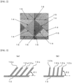
- FIGs. 1A and 1B a plan view of one aspect of the 3D patterned sheet used as the support of the adhesive patch according to the present invention ( FIG. 1A ) and an enlarged plan view of a part of the sheet ( FIG. 1B ) are illustrated.
- the 3D patterned sheet includes a plurality of figures 11 partitioned by lines. The outline of this figure 11 indicates the range of the figure.
- the figure 11 may include a part to which the number 11 is not assigned and may also refer to a part of the substrate of the sheet.
- the figures partitioned by the lines indicate figures divided into several parts by the boundary A.
- the figure according to the present invention may also include "representation of characters by a figure" and this "representation of characters by a figure” can express, for example, a logo in the sheet.
- a plurality of linearly extending protruded lines and recessed lines 12 are formed in parallel. More specifically, as illustrated in FIG. 1B , emboss processing is applied on the surface of the 3D patterned sheet (that is, the support of the adhesive patch according to the present invention) in the adjacent figures divided by the boundary A so that a plurality of lines is formed in parallel.
- the length direction of the protruded lines and recessed lines 12a of the figure 11a and the length direction of the protruded lines and recessed lines 12b of the figure 11b are formed in different directions.
- these protruded lines and recessed lines are formed in directions orthogonal to each other.
- the embossments (12a, 12b) linearly and parallelly processed are not parallel to each other but have different directions in the adjacent figures divided by the boundary A.
- the boundary A between the figure 11a and the figure 11b is formed in one aspect of the 3D patterned sheet by oppositely abutting the terminal end in the longitudinal direction of the protruded lines and recessed lines 12a in the figure 11a and the terminal end in the longitudinal direction of the protruded lines and recessed lines 12b in the figure 11b (refer to the part (A1) in FIG. 1B ).
- the boundary A between the figure 11a and the figure 11b in another aspect is formed by abutting the side surfaces of the protruded lines and recessed lines 12a (12b) in the figure 11a (11b) and the terminal end in the longitudinal direction of the protruded lines and recessed lines 12b (12a) in the figure 11b (11a) (refer to the part (A2) in FIG. 1B ).
- the embossment (protruded lines) linearly extending in the boundary A of the 3D patterned sheet may include aligned linear embossment or curved embossment or a combination thereof.
- the 3D patterned sheet may include not only the linearly extending embossment but also protruded parts (protruded lines) formed of dots, figures such as circles, quadrangles, and triangles, and character strings and figures formed by combining these dots, figures, and character strings with each other.
- FIG. 2 is an enlarged plan view illustrating another aspect of the 3D patterned sheet used as the support of the adhesive patch according to the present invention.
- the 3D patterned sheet of this aspect has a substantially square region (figure) divided into a downwardly protruded triangular region (figure), an upwardly protruded triangular region (figure), a region (figure) protruding to right, and a region (figure) protruding to left.
- This divided square forms a one-unit region (figure).
- a pattern is formed by forming a plurality of protruded lines and recessed lines in each triangular region (figure) in a one-unit region (figure).
- the boundary 14 formed by mutually abutting the protruded lines and recessed lines is formed similar to the boundary A previously described in FIG. 1B .
- the 3D patterned sheet of this aspect is formed by repeatedly forming the one-unit regions (the figures, that is, the pattern) in the upper, lower, left, and right directions. Grooves are formed in the boundary lines 15 where the one-unit regions (the figures, that is, the pattern) are adjacent to each other.
- a collection point 16 of the four boundary lines 15 generated by collecting the four one-unit regions (the figures, that is, the pattern) is not defined as a groove but defined as a protruded part.
- the walls of the protruded lines and recessed lines 12 are formed to be inclined by different inclination angles with respect to the base part in some of the figures 11 .
- the term "base part” refers to the surface of the 3D patterned sheet (support).
- the phrase "is formed to be inclined by different inclination angles with respect to the base part” means that the protruded lines are formed so that the walls of the protruded lines have various inclination angles with respect to the base surface.
- each of the walls of the protruded lines and recessed lines 12 is formed so that the inclination angle ⁇ 1 of the protruded lines and recessed lines 12a in the figure 11a (not illustrated in FIG. 3 ) with respect to the base part 13 (that is, the inclination ⁇ 1 of the protruded lines with respect to the base part 13) as illustrated in FIG. 3A and the inclination angle ⁇ 2 of the protruded lines and recessed lines 12b in the figure 11b (not illustrated in FIG. 3 ) with respect to the base part 13 (that is, the inclination ⁇ 2 of the protruded line part with respect to the base part 13) as illustrated in FIG. 3B are different.
- a constitution in which at least two kinds of inclination angles ( ⁇ 1 and ⁇ 2) are prepared, a first inclination angle ( ⁇ 1) may be applied to some of the figures 11 of the 3D patterned sheet, and the second inclination angle ( ⁇ 2) is applied to the remaining figures 11 may be employed.
- a constitution in which three or more inclination angles ( ⁇ 1, ⁇ 2, ⁇ 3, ..., and the like) are applied may be employed.
- an aspect including the protruded lines formed so that the walls of the protruded lines have not only the first inclination angle alone with respect to the base part 13 (the surface) but also the protruded lines formed so as to have the second inclination angle in addition to the protruded lines formed with the first inclination angle may be employed.
- the protruded lines and recessed lines 12 are formed so as to have different heights, serving as the physical parameter of the protruded lines and recessed lines 12, from the base part 13 toward the predetermined direction in the sheet.
- the "predetermined direction” means the longitudinal direction or the lateral direction of the sheet, or the oblique direction provided with respect to the longitudinal direction (or the lateral direction).
- a plurality of regions is provided for each of these directions and the protruded lines and recessed lines (embossment) are formed so that the protruded lines have different heights from the base part (sheet surface) of the sheet in adjacent regions.
- the regions provided for the predetermined direction may be the same as or different from the figures divided by the boundary as illustrated by the above boundary 14 and the like.
- a line segment orthogonal to a straight line heading toward a predetermined direction in the plane of the sheet refers to a line segment orthogonal to the longitudinal direction (that is, in the lateral direction) of the sheet, a line segment orthogonal to the lateral direction (that is, in the longitudinal direction) of the sheet, and a line segment orthogonal to the oblique direction of the sheet, for example, orthogonal to a 45 degree direction (that is, in the reverse oblique direction of 45 degrees).
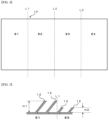
- a sheet 10 is partitioned into four regions E1 to E4 in the longitudinal direction by lines L1, L2, and L3 orthogonal to the lateral direction of the sheet 10.
- H1 and H2 are prepared as the heights of the protruded lines and recessed lines 12 from the base part 13 (the heights of the protruded lines from the base part).
- the height H1 is employed in the regions E1 and E3 and the height H2 is employed in the regions E2 and E4. This allows a configuration having different heights of the protruded lines and recessed lines 12 from the base part 13 (heights of the protruded lines from the base part) in the adjacent regions to be formed.
- FIG. 5 is a sectional view in which the boundary between the region E1 and the region E2 is a section where the heights of the protruded lines and recessed lines 12 from the base part 13 (heights of the protruded lines from the base part) appear.
- the height of the protruded lines and recessed lines 12 from the base part 13 can be selected, for example, from 0.14 mm to 0.3 mm.
- the 3D patterned sheet constituted as described above can be produced by engraving the grooves corresponding to the protruded lines and recessed lines 12 of the 3D patterned sheet onto the embossing roll with laser and heating a sheet material before providing the 3D pattern while the sheet is sandwiched between the embossing roll and a supporting roll.
- the 3D patterned sheet used as the support of the adhesive patch according to the present invention has different heights of the protruded lines and recessed lines 12 from the base part 13 (the heights of the protruded lines from the base part) depending on the region, and thus the texture and rigidity (flexibility) are different and logos, symbols, and the like can be indicated in a specific area. Therefore, a 3D patterned sheet is prepared so as to have a required texture and rigidity (or flexibility) at desired parts in the adhesive patch and to have the logos, medicinal names, or the symbols indicating them in specific regions. This 3D patterned sheet can be used as the support of the adhesive patch. As the heights of the protruded lines and recessed lines 12 from the base part 13 (the heights of the protruded lines from the base part) are higher, solidification by heating appears more obviously. And the region having high rigidity in the support can be made.
- the regions are determined to be four regions and the number of the different heights of the protruded lines and recessed lines 12 from the base part 13 (the heights of the protruded lines from the base part) is determined to be two.
- the boundary line may be determined to be a horizontal line or regions may be provided in a mesh shape using horizontal lines and vertical lines as the boundary lines.
- the boundary line may be an oblique line or may be not limited to the straight line and may be a curved line.
- the heights of the protruded lines and recessed lines 12 from the base part 13 may be continuously varied instead of dividing the regions as illustrated in the above aspect ( FIG. 5 ).
- the physical parameters of the 3D patterned sheet such as the widths W with respect to the protruded lines and recessed lines 12, the inclination angles ⁇ , the densities of the lines formed by the protruded lines and recessed lines 12, and a heating temperature in the processing may be set and used in addition to the heights of the protruded lines and recessed lines 12 (the heights of the protruded lines from the base part).
- the width W serving as the parameter refers to a variable representing the width of the protruded lines in a part of protruded lines and recessed lines 12 in one figure (that is, the width of the protruded line part of the linear embossment) as illustrated in FIG. 6 .
- the density of the lines formed by the protruded lines and recessed lines 12 serving as the parameter refers to a variable which shows, for example, the number of lines of the protruded lines and recessed lines 12 which are included in the unit length (that is, the number of the protruded lines in the linear embossment per unit width, so to say, a parameter reflecting the width of the protruded line parts and the width of the recces parts).
- At least one of these physical parameters may be different from each other toward a predetermined direction (in the adjacent regions) in the sheet.
- the width W serving as the parameter becomes wider, the rigidity of the part may increase more.
- the width W may theoretically be selected between 10 mm and 500 mm and suitable between 50 mm and 200 mm.
- the rigidity may increase.
- the rigidity may increase more.
- the rigidity may increase more.
- the heights of the protruded lines and recessed lines 12 from the base part 13 are usually determined to be, for example, 0.14 mm to 0.3 mm as described above.
- the 3D patterned sheet in which the surface of the side on the embossing roll is determined to be the front surface can be obtained by using the embossing roll having the groove corresponding to this height and the supporting roll and heating a sheet before processing while the sheet is sandwiched between these two rolls. In this case, the pattern is generated on the front surface side of the sheet. The pattern, however, may also be generated on the back surface depending on processing conditions.
- the back surface of the sheet is desirably flat.
- a 3D patterned sheet in which the design (the pattern) is prevented from appearing on the back surface can be produced by adjusting at least one of the pressures between the embossing roll and the supporting roll, the processing speed (the rotation speed of the rolls), and the processing temperature or adjusting the depth of the groove on the embossing roll to be shallow.
- the depth of the engraving in the engraved roll (embossing roll) for preventing the design (pattern) from appearing on the back surface as described above can be adequately selected within the range of, for example, 0.14 mm to 0.3 mm.
- the aspect illustrated in FIG. 4 described above is an aspect in which the heights of the protruded lines and recessed lines 12 from the base part 13 (the heights of the protruded lines from the base part) are varied in the four regions.
- the 3D patterned sheet in which relatively soft texture in the regions E11 and E13 compared with the texture in the region E12 is obtained, whereas relatively hard texture in the region E12 compared with the texture in the regions E11 and E13 is obtained can be produced by dividing the sheet into three regions of the regions E11, E12, and E13, varying the engraving depth in the engraved roll to 0.14 mm in the regions E11 and E13 and to 0.3 mm in the region E12 to carry out emboss processing.
- the difference in these textures depends on the difference in rigidity and can be detected as a difference in a drape coefficient (bending resistance) measured by, for example, a test in accordance with a drape coefficient method.
- the drape coefficient of the 3D patterned sheet is preferably, for example, 0.1 to 1.0 (in accordance with JIS L 1096 method G (drape coefficient method)) or the like.
- Examples of the various sheet materials for the materials of the 3D patterned sheet include paper such as impregnated paper, coated paper, high-quality paper, kraft paper, Japanese paper, and glassine paper; cellophane sheets and films; synthetic resin sheets and films such as films and sheets constituted by including a polyester-based resin such as polyethylene terephthalate and polybutylene terephthalate, a polyamide-based resin, an acetyl cellulose-based resin, a polylactic acid-based resin, a polyolefin-based resin such as polyethylene and polypropylene, a polyvinyl chloride-based resin, and a polycarbonate-based resin; the foamed material of a synthetic resin; a textile fabric such as a knitted fabric (also referred to as a knitted cloth), woven fabrics (also called a textile and a woof), and nonwoven fabrics; a leather cloth; and a laminate of two or more of these materials.
- paper such as impregnated paper, coated paper, high-quality paper
- the knitted fabric, the woven fabric, or the nonwoven fabric made of fibers of thermoplastic resins selected from the group consisting of the polyester-based resin such as polyethylene terephthalate and polybutylene terephthalate, the polyamide-based resin such as 6,6-nylon and 6-nylon, the acetyl cellulose-based resin such as triacetyl cellulose, and the polylactic acid-based resin are preferably used as the support.
- This sheet cloth has a structure knitted with a double knitting machine. The sheet cloth is characterized in that the knitted stitches of a three-dimensional structure overlap each other and thus the sheet cloth has clogged knitted stitches, large elasticity, and excellent stability.
- a flat woven fabric having a product basis weight of about 150 g/m 2 to about 200 g/m 2 , a woven-knitted fabric having a thickness of 2 mm or smaller, or the like can be used.
- the material of the 3D patterned sheet for example, a knitted fabric, a woven fabric, and a nonwoven fabric including at least polyester-based fibers such as polyester and modified polyester as fiber materials can be suitably employed.
- the sheet material (the knitted fabric, the woven fabric, and the nonwoven fabric) may include fiber materials in addition to the polyester-based fibers.
- fiber materials include fiber materials made of thermoplastic resins such as polyolefin-based fibers (such as polyethylene-based fibers and polypropylene-based fibers), acetyl cellulose-based fibers (such as triacetate-based fibers), polyamide-based fibers (such as 6,6-nylon fibers and 6-nylon fibers), and polyvinyl chloride-based fibers.
- thermoplastic resins such as polyolefin-based fibers (such as polyethylene-based fibers and polypropylene-based fibers), acetyl cellulose-based fibers (such as triacetate-based fibers), polyamide-based fibers (such as 6,6-nylon fibers and 6-nylon fibers), and polyvinyl chloride-based fibers.
- these knitted fabric, woven fabric, and nonwoven fabric for example, the knitted fabric, woven fabric, and nonwoven fabric having a product basis weight of 70 g/m 2 to 120 g/m 2 and preferably 85 g/m 2 to 105 g/m 2 or the knitted fabric, woven fabric, and nonwoven fabric having a thickness of 0.6 mm to 1.2 mm and preferably 0.75 mm to 0.95 mm, are suitably used as materials for the 3D patterned sheet.
- the pressure-sensitive adhesive layer is a sticky layer in which various active components such as medicines and transdermal absorption promoters are supported as desired.
- the pressure-sensitive adhesive layer may be constituted of a single layer or may be constituted of a plurality of layers, if desired.
- the pressure-sensitive adhesive layer can be a laminated layer formed by laminating a layer including a medicine and a pressure-sensitive adhesive and a layer including the pressure-sensitive adhesive (not including a medicine).
- the pressure-sensitive adhesive layer (also referred to as a plaster layer) is preferably a layer made of a sticky hydrogel or the like.
- the thickness of the layer and the viscosity of the gel are adequately selected depending on the purpose.
- a gel used as the plaster of a conventional adhesive patch can be used.
- one or more water-soluble polymers such as sodium alginate, gum arabic, gelatin, pullulan, pectin, polyvinyl pyrrolidone, polyvinyl alcohol, methyl cellulose, ethyl cellulose, sodium carboxymethyl cellulose, hydroxyethyl cellulose, hydroxypropyl cellulose, a polyacrylic acid, sodium polyacrylate, an acrylic acid copolymer, a maleic anhydride copolymer, and methyl vinyl ether are used as a main raw material.
- water-soluble polymers such as sodium alginate, gum arabic, gelatin, pullulan, pectin, polyvinyl pyrrolidone, polyvinyl alcohol, methyl cellulose, ethyl cellulose, sodium carboxymethyl cellulose, hydroxyethyl cellulose, hydroxypropyl cellulose, a polyacrylic acid, sodium polyacrylate, an acrylic acid copolymer
- a hydrous gel made by kneading a curing agent, a curing regulator, a mineral powder, a perfume, a pigment, water, and the like with this main raw material can be used.
- Each of the raw materials is adequately blended in an amount in such a degree that effects provided by the blend are sufficiently achieved and that quality deterioration and deterioration in use feeling, difficulty in handling in production, and the like due to excessive blend do not occur.
- transdermal absorbable medicines such as analgesics or antiinflammatory agents, coolants, and moisturizers.
- active components may be used singly or in combination of two or more of the active components.
- Each of these medicinal components is adequately blended in an amount in such a degree that medicinal effects provided by the blend are sufficiently achieved and skin irritation and the like due to excessive blending may not occur.
- the pressure-sensitive adhesive layer may be constituted by including an adhesive and a tackifying resin selected from a synthetic rubber-based pressure-sensitive adhesive such as a styrene-isoprene-styrene block copolymer, a natural rubber-based pressure-sensitive adhesive, a hydrogenated petroleum resin, a rosin, a hydrogenated rosin, a terpene resin, an acrylic pressure-sensitive adhesive, and a silicone-based pressure-sensitive adhesive.
- a synthetic rubber-based pressure-sensitive adhesive such as a styrene-isoprene-styrene block copolymer, a natural rubber-based pressure-sensitive adhesive, a hydrogenated petroleum resin, a rosin, a hydrogenated rosin, a terpene resin, an acrylic pressure-sensitive adhesive, and a silicone-based pressure-sensitive adhesive.
- liquid rubbers such as polybutene and polyisobutylene, softening agents (plasticizers) such as liquid paraffin, vegetable oil, and lanolin, percutaneous absorption promoters such as fatty acid esters and higher alcohols, and ultraviolet absorbers may be further blended, if necessary.
- softening agents such as liquid paraffin, vegetable oil, and lanolin
- percutaneous absorption promoters such as fatty acid esters and higher alcohols
- ultraviolet absorbers may be further blended, if necessary.
- the components described in the above ⁇ cataplasm> can be adequately blended.
- the release liner is adequately selected depending on the purpose in consideration of easy peelability from the pressure-sensitive adhesive layer, air permeability, water permeability, flexibility, and the like.
- the material of the release liner include a plastic film of polypropylene, polyethylene, polyester, polyurethane, polyvinyl chloride, polystyrene, polyethylene terephthalate, or other plastics; a plastic film obtained by subjecting one side or both sides of the plastic film to silicone processing; silicon-processed paper processed with silicon on a synthetic resin, synthetic paper, and synthetic fibers; aluminum foil; laminated paper formed by laminating kraft paper with polyethylene and the like that are colorless or colored.
- the material of the release liner may be used singly or in combination of two or more of the materials.
- the thickness of the release liner is adequately selected depending on the material property and the like. An excessively thick release liner tends to be easily released from the plaster layer, whereas an excessively thin release liner tends to be easily damaged. Therefore, the thickness should be carefully determined. Usually, the thickness of the release liner may be preferably determined to be 10 ⁇ m to 100 ⁇ m. The shape of the release liner may be a rectangle with rounded corners, a circle, and the like. The size of the release liner is the same as the size of the support provided with the pressure-sensitive adhesive layer or slightly larger.
- the release liner may be subjected to surface treatment such as emboss processing.
- figures such as arrows, character strings, and symbols may be printed on the release liner or the release liner may be colored.
- the adhesive patch according to the present invention can be produced by production methods known in the art such as a method for forming the pressure-sensitive adhesive layer on the surface opposite to the surface on which the pattern of protruded lines and recessed lines of the support (3D patterned sheet) is formed, and laminating the release liner on the formed pressure-sensitive adhesive layer or a method for forming the pressure-sensitive adhesive layer on the release liner, and laminating the support (3D patterned sheet) to pressure-sensitive adhesive layer on the surface of the support opposite to the surface having the pattern of the protruded lines and recessed lines of the support.
- the adhesive patch targeted by the present invention the same shape and size as those of conventional adhesive patches can be employed and various shapes and sizes can be selected depending on the attachment site (application site).
- the adhesive patch according to the present invention preferably has a rectangular shape having a longitudinal/width length ratio of 1/1 to 10/1.
- a knitted cloth that is a cloth knitted into a circular knitted fabric (interlock) using polyester-based fiber 100% processed yarn and has a product basis weight of 100 g/m 2 was used as the material.
- Each of the 3D patterns illustrated in FIG. 8 to FIG. 13 was transferred to one surface of the knitted cloth using an embossing roll to prepare 7 kinds of 3D patterned sheets. These 3D patterned sheets were used as supports.
- a pressure-sensitive adhesive layer was provided on the surface of the support opposite to the side on which the 3D pattern was formed, and a release liner was laminated so as to cover the surface of the pressure-sensitive adhesive layer to prepare an adhesive patch having a size of 14 cm ⁇ 10 cm.
- Example 1 An aspect in which a 3D pattern is formed by dividing a substantially square into four triangles the apexes of each of which headed to upward, downward, left, and right directions, determining this substantially square region to be a one-unit figure, and forming a plurality of protruded lines in the figures of each of the triangles in a one-unit figure (refer to FIG. 2 ).
- Example 2 ( FIG. 9 ): An aspect in which a 3D pattern is formed by arranging a plurality of figures having various approximately polygonal shapes and forming a plurality of protruded lines in the figures so as to obtain a visual effect such that the approximately semicircular arcs are arranged in the longitudinal direction (left to right direction in FIG. 9 ).
- Example 3 An aspect in which a 3D pattern is formed by providing a plurality of figures having various shapes, forming protruded lines such that respective lines are parallel with each other in each of the figures, and proving the protruded lines so that the directions of the protruded lines are different from each other in adjacent figure and, in some figures, forming protruded lines so that the inclination angles formed by the base part (front surface) and the walls of the protruded lines have an inclination angle different from the inclination angles in other figures in the formation of the protruded lines (refer to FIG. 1 ).
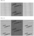
- Example 4 ( FIG. 11 ): An aspect formed by dividing the entire support into three regions, continuously forming the straight protruded lines at equal intervals so as to be parallel to each other in left and right regions, and forming character strings of "LEAD CHEMICAL" as one unit so as to be protruded parts aligned at substantially equal intervals in the center area.
- Example 5 An aspect formed by dividing the entire support into three regions, continuously forming the straight protruded lines at equal intervals so as to be parallel to each other in the left and right regions, and forming character strings of "LEAD CHEMICAL" as one unit so as to be recessed parts aligned at substantially equal intervals in the center area.
- Example 6 ( FIG. 13 ): An aspect formed by dividing the entire support into three regions, continuously forming the straight protruded lines at equal intervals so as to be parallel to each other in the left and right regions and forming character strings of "LEAD CHEMICAL” as one unit so as to be recessed parts aligned at substantially equal intervals, and forming character strings of "LEAD CHEMICAL” as one unit so as to be recessed parts aligned at substantially equal intervals in the center area.
- Example 7 An aspect formed by providing a plurality of figures having various polygon shapes, partitioning each of the figures with a linear region where no protruded lines are formed, providing the protruded lines within each of the figures so that the lines are parallel to each other, providing the orientations and widths of the protruded lines in different directions from each other through the boundary in the adjacent figures and arranging character strings of "(LOGO) LEAD CHEMICAL CO., LTD" as one unit in parallel at substantially equal intervals to each other on a part of the sheet to form protrusion and recess parts.
- JIS L 1096 method G (drape coefficient method) was employed. The test was carried out for the original cloth and the processed clothes (a processed cloth at 180°C and a processed cloth at 190°C). The results are listed in Table 1. Table 1 Original cloth Cloth processed at 180°C Cloth processed at 190°C Drape coefficient 0.121 0.182 0.222
Landscapes
- Health & Medical Sciences (AREA)
- Engineering & Computer Science (AREA)
- Public Health (AREA)
- Veterinary Medicine (AREA)
- Life Sciences & Earth Sciences (AREA)
- Animal Behavior & Ethology (AREA)
- General Health & Medical Sciences (AREA)
- Bioinformatics & Cheminformatics (AREA)
- Vascular Medicine (AREA)
- Heart & Thoracic Surgery (AREA)
- Biomedical Technology (AREA)
- Chemical & Material Sciences (AREA)
- Medicinal Chemistry (AREA)
- Pharmacology & Pharmacy (AREA)
- Epidemiology (AREA)
- Dermatology (AREA)
- Medicinal Preparation (AREA)
- Materials For Medical Uses (AREA)
- Adhesive Tapes (AREA)
Description
- The present invention relates to an adhesive patch, and particularly relates to an adhesive patch using a 3D patterned sheet of which the provided pattern varies its appearance depending on a viewing direction and the pattern appears three-dimensionally as the support of the adhesive patch.
- An adhesive patch applied as a percutaneous absorption external preparation is generally provided as an adhesive patch product including the adhesive patch and a package formed by hermetically packaging the adhesive patch.
- Generally, in the package of the adhesive patch product, the kind of the adhesive patch (medicine name and the like) contained in the package, the effect and efficacy of the adhesive patch, application methods (attaching method, application frequency, and the like), and the like are described. In accordance with this description, medicine providers and medicine users are checking the kind and usage of the adhesive patch. Furthermore, improved products have been developed so that, even after the adhesive patch is taken out from the package of the adhesive patch product, the kind and application method of the adhesive patch can be distinguished due to description of the name, kind, and usage of the adhesive patch by printing or the like on the surface of a release liner or a support.
- In order to distinguish the kind and name of the adhesive patch or to facilitate taking out the adhesive patch from a package and putting it into the package, application of unevenness (emboss) processing to the surface of a release liner or a support has been developed (refer to
Patent Document 1 to Patent Document 3). - On the other hand, an embossing roll on which the fine line grooves in a plurality of patterns having different cutting angles, cutting widths, densities, and cutting depths are formed by irradiation with laser beams on the outer peripheral surface of the roll main body has been developed (refer to Patent Document 4).
-
- Patent Document 1:
Japanese Patent Application Publication No. H07-126156 JP H07-126156 A - Patent Document 2:
Japanese Patent Application Publication No. S63-175128 JP S63-175128A - Patent Document 3:
Japanese Patent Application Publication No. 2001-231812 JP 2001-231812 A - Patent Document 4:
Japanese Utility Registration Model No. 3155463 - Further prior art documents include
US 2002/110585 andWO 98/29231 US 2002/110585 discloses the creation of a textured backing for a drug delivery patch to improve the wrinkle resistance, and/or permeability of the patch.WO 98/29231 - As described in
Patent Documents 1 to 3, an adhesive patch in which simple emboss processing is applied to the surface of the support, that is, the surface opposite to the surface in contact with a pressure-sensitive adhesive layer has been developed. - On the other hand, in the embossing roll described in
Patent Document 4, the fine line grooves in a plurality of patterns are formed on the outer peripheral surface of the roll main body by laser beam irradiation and the 3D patterned sheet on which the fine line grooves are transferred can be produced. However, no development has yet to be made for a 3D patterned sheet in which making a difference in appearance for each part is considered and artistic patterns appealing to the eyesight of the viewer are provided. Furthermore, the adhesive patch using such a 3D patterned sheet as a support has yet to be developed. - The inventors of the present invention have studied employment of a 3D patterned sheet that has yet to be employed as the support of an adhesive patch. First, the inventors of the present invention have found that the rigidity (flexibility) of the sheet can be controlled by adequately selecting the physical parameters such as the height of the protruded lines and the width of protruded lines and recessed lines that are formed as fine line grooves on the 3D patterned sheet. The inventors of the present invention have found that the 3D patterned sheet that can easily change the flexibility depending on each part requiring rigidity or flexibility and for which the final product having suitable human sense and sensibility of touch and texture is considered is obtained by varying the physical parameters of the protruded lines and recessed lines in the sheet and an adhesive patch having excellent design and excellent usability during use is obtained by using the 3D patterned sheet as the support of the adhesive patch. Thus, the inventors of the present invention have accomplished the present invention.
- Therefore, the present invention relates to an adhesive patch including a medicine, comprising:
- a support;
- a pressure-sensitive adhesive layer provided on the support; and
- a release liner attached on the pressure-sensitive adhesive layer so as to cover the surface of the pressure-sensitive adhesive layer,
- wherein the support is a 3D patterned sheet characterized in that a plurality of parallel protruded lines and recessed lines which extend linearly from a base part are formed in a plurality of regions, whereby the appearance of the protruded lines and recessed lines is different for each region, and the 3D patterned sheet is formed so that one surface of the sheet is determined to be a front surface and the other surface is determined to be a back surface, the front surface having a pattern formed by protruded lines and recessed lines, the back surface being smooth and the pressure sensitive layer being provided on the back surface,
- walls of the protruded lines and recessed lines in some of the regions are formed to be inclined by different inclination angles with respect to the base part serving as physical parameters of the protruded lines and recessed lines, and toward a predetermined direction in the sheet.
- In the adhesive patch according to the present invention, the physical parameters of the 3D patterned sheet are preferably constituted of the widths of the protruded lines and recessed lines, the inclination angles, the densities of the lines formed by the protruded lines and recessed lines, and a heating temperature in 3D pattern processing in addition to the heights of the protruded lines, and at least one of the physical parameters is preferably different from each other.
- In the adhesive patch according to the present invention, the 3D patterned sheet is preferably divided into a plurality of regions toward a predetermined direction in the sheet, and at least one of the physical parameters is preferably different from each other in adjacent regions.
- In the adhesive patch according to the present invention, the 3D patterned sheet is preferably divided into a plurality of regions by line segments orthogonal in the surface of the sheet to a line heading toward a predetermined direction in the sheet.
- In the adhesive patch according to the present invention, the 3D patterned sheet is preferably formed so that one surface of the sheet is determined to be a front surface and the other surface is determined to be a back surface, the front surface having a pattern formed by protruded lines and recessed lines, the back surface being smooth, and the pressure-sensitive adhesive layer being provided on the back surface.
- In the adhesive patch according to the present invention, the support including the 3D patterned sheet is particularly preferably formed of a knitted fabric, a woven fabric, or a nonwoven fabric made of fibers of at least one thermoplastic resin selected from the group consisting of a polyester-based resin, a polyamide-based resin, an acetyl cellulose-based resin, and a polylactic acid-based resin.
- In the adhesive patch according to the present invention, the 3D patterned sheet produced by varying the heights of the protruded lines from the base part toward the predetermined direction in the sheet is used as the support. Application of the adhesive patch onto a human skin allows artistic appearance of the adhesive patch to be different depending on a direction to be seen or a part to be seen and the touch to be also excellent.
- In the adhesive patch according to the present invention, not only the kind of the adhesive patch (for example, an included medicine) and a method for applying the adhesive patch can be distinguished by changing the 3D pattern of the support but also the kind of the adhesive patch and the included medicine can be distinguished during the application onto the skin. Consequently, this adhesive patch can prevent inappropriate use and abuse.
- The adhesive patch according to the present invention allows the kind of the adhesive patch (a formulated medicine, an application method, and the like) to be distinguished by the 3D pattern provided in the 3D patterned sheet used as the support. Consequently, the adhesive patch does not cause problems by printing using ink, that is, contamination to the pressure-sensitive adhesive layer (medicine-containing layer) due to penetration of the ink into the inside of a sheet made of a nonwoven fabric and the like used as the support and occurrence of bleeding at the printed place on the surface of the support (a nonwoven fabric) due to penetration of the component included in the pressure-sensitive adhesive layer into the inside of the support (a nonwoven fabric and the like).
-
- [
FIG. 1] FIGs. 1A and 1B are views illustrating one aspect of a 3D patterned sheet used as the support of the adhesive patch according to the present invention.FIG. 1A is the plan view of the 3D patterned sheet andFIG. 1B is the enlarged plan view of a part of the 3D patterned sheet. - [
FIG. 2] FIG. 2 is a view illustrating another aspect of the 3D patterned sheet used as the support of the adhesive patch according to the present invention and a view illustrating an enlarged plan view of a part of the 3D patterned sheet. - [
FIG. 3] FIGs. 3A and 3B are views illustrating the section of the 3D patterned sheet used as the support of the adhesive patch according to the present invention and are sectional views each illustrating the cases where the side walls of protruded lines and recessed lines are formed so as to have an angle θ1 (FIG. 3A ) and have an angle θ2 (FIG. 3B ) with respect to a base part. - [
FIG. 4] FIG. 4 is a plan view illustrating one example of the 3D patterned sheet used as the support of the adhesive patch according to the present invention that has partitioned regions in the longitudinal direction of the sheet. - [
FIG. 5] FIG. 5 is a sectional view of one example of the 3D patterned sheet used as the support of the adhesive patch according to the present invention in which the protruded lines and recessed lines are formed in the partitioned region so as to have different heights. - [
FIG. 6] FIG. 6 is an enlarged plan view enlarging the protruded lines and recessed lines of the 3D patterned sheet used as the support of the adhesive patch according to the present invention. - [
FIG. 7] FIG. 7 is a plan view illustrating one example of the 3D patterned sheet used as the support of the adhesive patch according to the present invention that has partitioned regions in the longitudinal direction of the sheet. - [
FIG. 8] FIG. 8 is a view illustrating the 3D pattern of the 3D patterned sheet used as the support of the adhesive patch prepared in Examples. - [
FIG. 9] FIG. 9 is a view illustrating the 3D pattern of the 3D patterned sheet used as the support of the adhesive patch prepared in Examples. - [
FIG. 10] FIG. 10 is a view illustrating the 3D pattern of the 3D patterned sheet being the support of the adhesive patch prepared in Examples. - [
FIG. 11] FIG. 11 is a view illustrating the 3D pattern of the 3D patterned sheet used as the support of the adhesive patch prepared in Examples. - [
FIG. 12] FIG. 12 is a view illustrating the 3D pattern of the 3D patterned sheet used as the support of the adhesive patch prepared in Examples. - [
FIG. 13] FIG. 13 is a view illustrating the 3D pattern of the 3D patterned sheet used as the support of the adhesive patch prepared in Examples. - [
FIG. 14] FIG. 14 is a view illustrating the 3D pattern of the 3D patterned sheet used as the support of the adhesive patch prepared in Examples. - The present invention targets an adhesive patch including a support; at least a pressure-sensitive adhesive layer provided on the support; and a release liner attached on the pressure-sensitive adhesive layer so as to cover the surface of the pressure-sensitive adhesive layer. Formulations such as cataplasms and plasters can be applied to the adhesive patch targeted by the present invention.
- Hereinafter, each layer constituting the adhesive patch according to the present invention will be described in detail.
- The 3D patterned sheet is used as the support in the adhesive patch according to the present invention. Hereinafter, the 3D patterned sheet will be described with reference to the attached drawings. In each of the drawings, the same reference numerals are assigned to the same constituent elements and redundant descriptions are omitted.
- In the present invention, the term "3D patterned sheet" collectively refers to sheets that provide the protruded lines and recessed lines (embossment) different for each region (figure), whereby the appearance of the protruded lines and recessed lines (embossment) is different for each region (figure) and different visual effects depending on the viewing direction and the viewing part are intended to be obtained.
- In
FIGs. 1A and 1B , a plan view of one aspect of the 3D patterned sheet used as the support of the adhesive patch according to the present invention (FIG. 1A ) and an enlarged plan view of a part of the sheet (FIG. 1B ) are illustrated. The 3D patterned sheet includes a plurality offigures 11 partitioned by lines. The outline of thisfigure 11 indicates the range of the figure. Thefigure 11 may include a part to which thenumber 11 is not assigned and may also refer to a part of the substrate of the sheet. As illustrated inFIG. 1B , the figures partitioned by the lines indicate figures divided into several parts by the boundary A. The figure according to the present invention may also include "representation of characters by a figure" and this "representation of characters by a figure" can express, for example, a logo in the sheet. - On the inside and outside of the profile line in the
figure 11 illustrated inFIG. 1 , a plurality of linearly extending protruded lines and recessedlines 12 are formed in parallel. More specifically, as illustrated inFIG. 1B , emboss processing is applied on the surface of the 3D patterned sheet (that is, the support of the adhesive patch according to the present invention) in the adjacent figures divided by the boundary A so that a plurality of lines is formed in parallel. - As illustrated in the enlarged plan view of
FIG. 1B , the length direction of the protruded lines and recessed lines 12a of the figure 11a and the length direction of the protruded lines and recessedlines 12b of the figure 11b are formed in different directions. In the aspect illustrated inFIG. 1B , these protruded lines and recessed lines are formed in directions orthogonal to each other. In other words, as illustrated inFIG. 1B , the embossments (12a, 12b) linearly and parallelly processed are not parallel to each other but have different directions in the adjacent figures divided by the boundary A. - In the 3D patterned sheet according to this aspect, the boundary A between the figure 11a and the figure 11b is formed in one aspect of the 3D patterned sheet by oppositely abutting the terminal end in the longitudinal direction of the protruded lines and recessed lines 12a in the figure 11a and the terminal end in the longitudinal direction of the protruded lines and recessed
lines 12b in the figure 11b (refer to the part (A1) inFIG. 1B ). The boundary A between the figure 11a and the figure 11b in another aspect is formed by abutting the side surfaces of the protruded lines and recessed lines 12a (12b) in the figure 11a (11b) and the terminal end in the longitudinal direction of the protruded lines and recessedlines 12b (12a) in the figure 11b (11a) (refer to the part (A2) inFIG. 1B ). - In addition to the aspects illustrated in
FIGs. 1A and 1B , the embossment (protruded lines) linearly extending in the boundary A of the 3D patterned sheet may include aligned linear embossment or curved embossment or a combination thereof. - The 3D patterned sheet may include not only the linearly extending embossment but also protruded parts (protruded lines) formed of dots, figures such as circles, quadrangles, and triangles, and character strings and figures formed by combining these dots, figures, and character strings with each other.
-
FIG. 2 is an enlarged plan view illustrating another aspect of the 3D patterned sheet used as the support of the adhesive patch according to the present invention. - As illustrated in
FIG. 2 , the 3D patterned sheet of this aspect has a substantially square region (figure) divided into a downwardly protruded triangular region (figure), an upwardly protruded triangular region (figure), a region (figure) protruding to right, and a region (figure) protruding to left. This divided square forms a one-unit region (figure). A pattern is formed by forming a plurality of protruded lines and recessed lines in each triangular region (figure) in a one-unit region (figure). In the one-unit region (figure), that is, in the substantially square area (figure) formed of the regions of the four triangles (figures), theboundary 14 formed by mutually abutting the protruded lines and recessed lines is formed similar to the boundary A previously described inFIG. 1B . The 3D patterned sheet of this aspect is formed by repeatedly forming the one-unit regions (the figures, that is, the pattern) in the upper, lower, left, and right directions. Grooves are formed in theboundary lines 15 where the one-unit regions (the figures, that is, the pattern) are adjacent to each other. Acollection point 16 of the fourboundary lines 15 generated by collecting the four one-unit regions (the figures, that is, the pattern) is not defined as a groove but defined as a protruded part. - On the surface of the 3D patterned sheet used as the support of the adhesive patch according to the present invention, the walls of the protruded lines and recessed
lines 12 are formed to be inclined by different inclination angles with respect to the base part in some of thefigures 11 . The term "base part" refers to the surface of the 3D patterned sheet (support). The phrase "is formed to be inclined by different inclination angles with respect to the base part" means that the protruded lines are formed so that the walls of the protruded lines have various inclination angles with respect to the base surface. - For example, each of the walls of the protruded lines and recessed
lines 12 is formed so that the inclination angle θ1 of the protruded lines and recessed lines 12a in the figure 11a (not illustrated inFIG. 3 ) with respect to the base part 13 (that is, the inclination θ1 of the protruded lines with respect to the base part 13) as illustrated inFIG. 3A and the inclination angle θ2 of the protruded lines and recessedlines 12b in the figure 11b (not illustrated inFIG. 3 ) with respect to the base part 13 (that is, the inclination θ2 of the protruded line part with respect to the base part 13) as illustrated inFIG. 3B are different. - As described above, a constitution in which at least two kinds of inclination angles (θ1 and θ2) are prepared, a first inclination angle (θ1) may be applied to some of the
figures 11 of the 3D patterned sheet, and the second inclination angle (θ2) is applied to the remainingfigures 11 may be employed. As a matter of course, a constitution in which three or more inclination angles (θ1, θ2, θ3, ..., and the like) are applied may be employed. - In one
figure 11 , an aspect including the protruded lines formed so that the walls of the protruded lines have not only the first inclination angle alone with respect to the base part 13 (the surface) but also the protruded lines formed so as to have the second inclination angle in addition to the protruded lines formed with the first inclination angle may be employed. - In the 3D patterned sheet used as the support of the adhesive patch according to the present invention, the protruded lines and recessed
lines 12 are formed so as to have different heights, serving as the physical parameter of the protruded lines and recessedlines 12, from thebase part 13 toward the predetermined direction in the sheet. The "predetermined direction" means the longitudinal direction or the lateral direction of the sheet, or the oblique direction provided with respect to the longitudinal direction (or the lateral direction). A plurality of regions is provided for each of these directions and the protruded lines and recessed lines (embossment) are formed so that the protruded lines have different heights from the base part (sheet surface) of the sheet in adjacent regions. The regions provided for the predetermined direction may be the same as or different from the figures divided by the boundary as illustrated by theabove boundary 14 and the like. - In the present invention, a line segment orthogonal to a straight line heading toward a predetermined direction in the plane of the sheet refers to a line segment orthogonal to the longitudinal direction (that is, in the lateral direction) of the sheet, a line segment orthogonal to the lateral direction (that is, in the longitudinal direction) of the sheet, and a line segment orthogonal to the oblique direction of the sheet, for example, orthogonal to a 45 degree direction (that is, in the reverse oblique direction of 45 degrees).
- For example, as illustrated in
FIG. 4 , a sheet 10 is partitioned into four regions E1 to E4 in the longitudinal direction by lines L1, L2, and L3 orthogonal to the lateral direction of the sheet 10. For example, H1 and H2 are prepared as the heights of the protruded lines and recessedlines 12 from the base part 13 (the heights of the protruded lines from the base part). The height H1 is employed in the regions E1 and E3 and the height H2 is employed in the regions E2 and E4. This allows a configuration having different heights of the protruded lines and recessedlines 12 from the base part 13 (heights of the protruded lines from the base part) in the adjacent regions to be formed. -
FIG. 5 is a sectional view in which the boundary between the region E1 and the region E2 is a section where the heights of the protruded lines and recessedlines 12 from the base part 13 (heights of the protruded lines from the base part) appear. The height of the protruded lines and recessedlines 12 from the base part 13 (that is, the heights H1 and H2 of the protruded line parts of embossment from the base part 13) can be selected, for example, from 0.14 mm to 0.3 mm. - The 3D patterned sheet constituted as described above can be produced by engraving the grooves corresponding to the protruded lines and recessed
lines 12 of the 3D patterned sheet onto the embossing roll with laser and heating a sheet material before providing the 3D pattern while the sheet is sandwiched between the embossing roll and a supporting roll. - The 3D patterned sheet used as the support of the adhesive patch according to the present invention has different heights of the protruded lines and recessed
lines 12 from the base part 13 (the heights of the protruded lines from the base part) depending on the region, and thus the texture and rigidity (flexibility) are different and logos, symbols, and the like can be indicated in a specific area. Therefore, a 3D patterned sheet is prepared so as to have a required texture and rigidity (or flexibility) at desired parts in the adhesive patch and to have the logos, medicinal names, or the symbols indicating them in specific regions. This 3D patterned sheet can be used as the support of the adhesive patch. As the heights of the protruded lines and recessedlines 12 from the base part 13 (the heights of the protruded lines from the base part) are higher, solidification by heating appears more obviously. And the region having high rigidity in the support can be made. - In the above aspect (refer to
FIG. 4 and FIG. 5 ), the regions are determined to be four regions and the number of the different heights of the protruded lines and recessedlines 12 from the base part 13 (the heights of the protruded lines from the base part) is determined to be two. This, however, is merely an example. A plurality of regions can be employed and the number of the kinds of the heights can be determined to be three or more in the case where the number of the regions is three or more. As the method for forming the regions, the boundary line may be determined to be a horizontal line or regions may be provided in a mesh shape using horizontal lines and vertical lines as the boundary lines. The boundary line may be an oblique line or may be not limited to the straight line and may be a curved line. The heights of the protruded lines and recessedlines 12 from the base part 13 (the heights of the protruded lines from the base part) may be continuously varied instead of dividing the regions as illustrated in the above aspect (FIG. 5 ). - In the 3D patterned sheet used as the support of the adhesive patch according to the present invention, the physical parameters of the 3D patterned sheet such as the widths W with respect to the protruded lines and recessed
lines 12, the inclination angles θ, the densities of the lines formed by the protruded lines and recessedlines 12, and a heating temperature in the processing may be set and used in addition to the heights of the protruded lines and recessed lines 12 (the heights of the protruded lines from the base part). - For example, the width W serving as the parameter refers to a variable representing the width of the protruded lines in a part of protruded lines and recessed
lines 12 in one figure (that is, the width of the protruded line part of the linear embossment) as illustrated inFIG. 6 . The density of the lines formed by the protruded lines and recessedlines 12 serving as the parameter refers to a variable which shows, for example, the number of lines of the protruded lines and recessedlines 12 which are included in the unit length (that is, the number of the protruded lines in the linear embossment per unit width, so to say, a parameter reflecting the width of the protruded line parts and the width of the recces parts). - In another aspect of the 3D patterned sheet, at least one of these physical parameters may be different from each other toward a predetermined direction (in the adjacent regions) in the sheet.
- As the width W serving as the parameter becomes wider, the rigidity of the part may increase more. For example, the width W may theoretically be selected between 10 mm and 500 mm and suitable between 50 mm and 200 mm.
- As the density of the lines serving as the parameter becomes higher, the rigidity may increase.
- As the inclination angle serving as the parameter becomes smaller, the rigidity may increase more.
- As the heating temperature in the processing (that is, the temperature in emboss processing while the sheet material sandwiched between the embossing roll and the supporting roll as described above) serving as the parameter becomes higher, the rigidity may increase more.
- In one aspect of the 3D patterned sheet, the heights of the protruded lines and recessed
lines 12 from the base part 13 (the heights of the protruded lines from the base part) are usually determined to be, for example, 0.14 mm to 0.3 mm as described above. The 3D patterned sheet in which the surface of the side on the embossing roll is determined to be the front surface can be obtained by using the embossing roll having the groove corresponding to this height and the supporting roll and heating a sheet before processing while the sheet is sandwiched between these two rolls. In this case, the pattern is generated on the front surface side of the sheet. The pattern, however, may also be generated on the back surface depending on processing conditions. In the adhesive patch according to the present invention, which is the final product produced using the produced 3D patterned sheet, the back surface of the sheet is desirably flat. In accordance with a method for obtaining the 3D patterned sheet having a flat back surface, a 3D patterned sheet in which the design (the pattern) is prevented from appearing on the back surface can be produced by adjusting at least one of the pressures between the embossing roll and the supporting roll, the processing speed (the rotation speed of the rolls), and the processing temperature or adjusting the depth of the groove on the embossing roll to be shallow. - The depth of the engraving in the engraved roll (embossing roll) for preventing the design (pattern) from appearing on the back surface as described above can be adequately selected within the range of, for example, 0.14 mm to 0.3 mm.
- The aspect illustrated in
FIG. 4 described above is an aspect in which the heights of the protruded lines and recessedlines 12 from the base part 13 (the heights of the protruded lines from the base part) are varied in the four regions. For example, as illustrated inFIG. 7 , the 3D patterned sheet in which relatively soft texture in the regions E11 and E13 compared with the texture in the region E12 is obtained, whereas relatively hard texture in the region E12 compared with the texture in the regions E11 and E13 is obtained can be produced by dividing the sheet into three regions of the regions E11, E12, and E13, varying the engraving depth in the engraved roll to 0.14 mm in the regions E11 and E13 and to 0.3 mm in the region E12 to carry out emboss processing. The difference in these textures depends on the difference in rigidity and can be detected as a difference in a drape coefficient (bending resistance) measured by, for example, a test in accordance with a drape coefficient method. - Considering the use as the support of the adhesive patch according to the present invention, that is, considering a handling property during using the adhesive patch and skin followability during application, the drape coefficient of the 3D patterned sheet is preferably, for example, 0.1 to 1.0 (in accordance with JIS L 1096 method G (drape coefficient method)) or the like.
- Examples of the various sheet materials for the materials of the 3D patterned sheet include paper such as impregnated paper, coated paper, high-quality paper, kraft paper, Japanese paper, and glassine paper; cellophane sheets and films; synthetic resin sheets and films such as films and sheets constituted by including a polyester-based resin such as polyethylene terephthalate and polybutylene terephthalate, a polyamide-based resin, an acetyl cellulose-based resin, a polylactic acid-based resin, a polyolefin-based resin such as polyethylene and polypropylene, a polyvinyl chloride-based resin, and a polycarbonate-based resin; the foamed material of a synthetic resin; a textile fabric such as a knitted fabric (also referred to as a knitted cloth), woven fabrics (also called a textile and a woof), and nonwoven fabrics; a leather cloth; and a laminate of two or more of these materials.
- Out of these materials, the knitted fabric, the woven fabric, or the nonwoven fabric made of fibers of thermoplastic resins selected from the group consisting of the polyester-based resin such as polyethylene terephthalate and polybutylene terephthalate, the polyamide-based resin such as 6,6-nylon and 6-nylon, the acetyl cellulose-based resin such as triacetyl cellulose, and the polylactic acid-based resin are preferably used as the support.
- For example, a knitted fabric that is a cloth knitted into a circular knitted fabric (interlock = both sides knit) using polyester-based fiber 100% processed yarn and has a product basis weight (also referred to as a mass per unit area or an area density) of about 95 g/m2 to about 110 g/m2 can be used as the material. This sheet cloth has a structure knitted with a double knitting machine. The sheet cloth is characterized in that the knitted stitches of a three-dimensional structure overlap each other and thus the sheet cloth has clogged knitted stitches, large elasticity, and excellent stability.
- Alternatively, a flat woven fabric having a product basis weight of about 150 g/m2 to about 200 g/m2, a woven-knitted fabric having a thickness of 2 mm or smaller, or the like can be used.
- In particular, as the material of the 3D patterned sheet, for example, a knitted fabric, a woven fabric, and a nonwoven fabric including at least polyester-based fibers such as polyester and modified polyester as fiber materials can be suitably employed. The sheet material (the knitted fabric, the woven fabric, and the nonwoven fabric) may include fiber materials in addition to the polyester-based fibers. Examples of such fiber materials include fiber materials made of thermoplastic resins such as polyolefin-based fibers (such as polyethylene-based fibers and polypropylene-based fibers), acetyl cellulose-based fibers (such as triacetate-based fibers), polyamide-based fibers (such as 6,6-nylon fibers and 6-nylon fibers), and polyvinyl chloride-based fibers.
- From the viewpoint of the support of the adhesive patch, these knitted fabric, woven fabric, and nonwoven fabric, for example, the knitted fabric, woven fabric, and nonwoven fabric having a product basis weight of 70 g/m2 to 120 g/m2 and preferably 85 g/m2 to 105 g/m2 or the knitted fabric, woven fabric, and nonwoven fabric having a thickness of 0.6 mm to 1.2 mm and preferably 0.75 mm to 0.95 mm, are suitably used as materials for the 3D patterned sheet.
- The pressure-sensitive adhesive layer is a sticky layer in which various active components such as medicines and transdermal absorption promoters are supported as desired. The pressure-sensitive adhesive layer may be constituted of a single layer or may be constituted of a plurality of layers, if desired. In the case where the pressure-sensitive adhesive layer is constituted of a plurality of layers, the pressure-sensitive adhesive layer can be a laminated layer formed by laminating a layer including a medicine and a pressure-sensitive adhesive and a layer including the pressure-sensitive adhesive (not including a medicine).
- In the case where a cataplasm is employed as the formulation of the adhesive patch, the pressure-sensitive adhesive layer (also referred to as a plaster layer) is preferably a layer made of a sticky hydrogel or the like. The thickness of the layer and the viscosity of the gel are adequately selected depending on the purpose.
- As the sticky hydrous gel, a gel used as the plaster of a conventional adhesive patch can be used. For example, one or more water-soluble polymers such as sodium alginate, gum arabic, gelatin, pullulan, pectin, polyvinyl pyrrolidone, polyvinyl alcohol, methyl cellulose, ethyl cellulose, sodium carboxymethyl cellulose, hydroxyethyl cellulose, hydroxypropyl cellulose, a polyacrylic acid, sodium polyacrylate, an acrylic acid copolymer, a maleic anhydride copolymer, and methyl vinyl ether are used as a main raw material. A hydrous gel made by kneading a curing agent, a curing regulator, a mineral powder, a perfume, a pigment, water, and the like with this main raw material can be used. Each of the raw materials is adequately blended in an amount in such a degree that effects provided by the blend are sufficiently achieved and that quality deterioration and deterioration in use feeling, difficulty in handling in production, and the like due to excessive blend do not occur.
- Preferable examples of various active components include transdermal absorbable medicines such as analgesics or antiinflammatory agents, coolants, and moisturizers. These active components may be used singly or in combination of two or more of the active components. Each of these medicinal components is adequately blended in an amount in such a degree that medicinal effects provided by the blend are sufficiently achieved and skin irritation and the like due to excessive blending may not occur.
- In the case where a plaster agent is employed as the formulation of the adhesive patch, the pressure-sensitive adhesive layer may be constituted by including an adhesive and a tackifying resin selected from a synthetic rubber-based pressure-sensitive adhesive such as a styrene-isoprene-styrene block copolymer, a natural rubber-based pressure-sensitive adhesive, a hydrogenated petroleum resin, a rosin, a hydrogenated rosin, a terpene resin, an acrylic pressure-sensitive adhesive, and a silicone-based pressure-sensitive adhesive. To the pressure-sensitive adhesive layer, liquid rubbers such as polybutene and polyisobutylene, softening agents (plasticizers) such as liquid paraffin, vegetable oil, and lanolin, percutaneous absorption promoters such as fatty acid esters and higher alcohols, and ultraviolet absorbers may be further blended, if necessary.
- As the various active components, the components described in the above <cataplasm> can be adequately blended.
- The release liner is adequately selected depending on the purpose in consideration of easy peelability from the pressure-sensitive adhesive layer, air permeability, water permeability, flexibility, and the like. In general, preferable examples of the material of the release liner include a plastic film of polypropylene, polyethylene, polyester, polyurethane, polyvinyl chloride, polystyrene, polyethylene terephthalate, or other plastics; a plastic film obtained by subjecting one side or both sides of the plastic film to silicone processing; silicon-processed paper processed with silicon on a synthetic resin, synthetic paper, and synthetic fibers; aluminum foil; laminated paper formed by laminating kraft paper with polyethylene and the like that are colorless or colored. The material of the release liner may be used singly or in combination of two or more of the materials.
- The thickness of the release liner is adequately selected depending on the material property and the like. An excessively thick release liner tends to be easily released from the plaster layer, whereas an excessively thin release liner tends to be easily damaged. Therefore, the thickness should be carefully determined. Usually, the thickness of the release liner may be preferably determined to be 10 µm to 100 µm. The shape of the release liner may be a rectangle with rounded corners, a circle, and the like. The size of the release liner is the same as the size of the support provided with the pressure-sensitive adhesive layer or slightly larger.
- In order to facilitate the release of the release liner from the pressure-sensitive adhesive layer, the release liner may be subjected to surface treatment such as emboss processing.
- In order to describe and illustrate the mark for peeling and/or the kind of the adhesive patch and the method for attaching the adhesive patch, figures such as arrows, character strings, and symbols may be printed on the release liner or the release liner may be colored.
- The adhesive patch according to the present invention can be produced by production methods known in the art such as a method for forming the pressure-sensitive adhesive layer on the surface opposite to the surface on which the pattern of protruded lines and recessed lines of the support (3D patterned sheet) is formed, and laminating the release liner on the formed pressure-sensitive adhesive layer or a method for forming the pressure-sensitive adhesive layer on the release liner, and laminating the support (3D patterned sheet) to pressure-sensitive adhesive layer on the surface of the support opposite to the surface having the pattern of the protruded lines and recessed lines of the support.
- In the adhesive patch targeted by the present invention, the same shape and size as those of conventional adhesive patches can be employed and various shapes and sizes can be selected depending on the attachment site (application site). Out of these shapes, the adhesive patch according to the present invention preferably has a rectangular shape having a longitudinal/width length ratio of 1/1 to 10/1.
- Hereinafter, the present invention will be described more specifically with reference to Examples. The present invention, however, is not limited to Examples in any case.
- A knitted cloth that is a cloth knitted into a circular knitted fabric (interlock) using polyester-based fiber 100% processed yarn and has a product basis weight of 100 g/m2 was used as the material. Each of the 3D patterns illustrated in
FIG. 8 to FIG. 13 was transferred to one surface of the knitted cloth using an embossing roll to prepare 7 kinds of 3D patterned sheets. These 3D patterned sheets were used as supports. - A pressure-sensitive adhesive layer was provided on the surface of the support opposite to the side on which the 3D pattern was formed, and a release liner was laminated so as to cover the surface of the pressure-sensitive adhesive layer to prepare an adhesive patch having a size of 14 cm × 10 cm.
- Example 1 (
FIG. 8 ): An aspect in which a 3D pattern is formed by dividing a substantially square into four triangles the apexes of each of which headed to upward, downward, left, and right directions, determining this substantially square region to be a one-unit figure, and forming a plurality of protruded lines in the figures of each of the triangles in a one-unit figure (refer toFIG. 2 ). - Example 2 (
FIG. 9 ): An aspect in which a 3D pattern is formed by arranging a plurality of figures having various approximately polygonal shapes and forming a plurality of protruded lines in the figures so as to obtain a visual effect such that the approximately semicircular arcs are arranged in the longitudinal direction (left to right direction inFIG. 9 ). - Example 3 (
FIG. 10 ): An aspect in which a 3D pattern is formed by providing a plurality of figures having various shapes, forming protruded lines such that respective lines are parallel with each other in each of the figures, and proving the protruded lines so that the directions of the protruded lines are different from each other in adjacent figure and, in some figures, forming protruded lines so that the inclination angles formed by the base part (front surface) and the walls of the protruded lines have an inclination angle different from the inclination angles in other figures in the formation of the protruded lines (refer toFIG. 1 ). - Example 4 (
FIG. 11 ): An aspect formed by dividing the entire support into three regions, continuously forming the straight protruded lines at equal intervals so as to be parallel to each other in left and right regions, and forming character strings of "LEAD CHEMICAL" as one unit so as to be protruded parts aligned at substantially equal intervals in the center area. - Example 5 (
FIG. 12 ): An aspect formed by dividing the entire support into three regions, continuously forming the straight protruded lines at equal intervals so as to be parallel to each other in the left and right regions, and forming character strings of "LEAD CHEMICAL" as one unit so as to be recessed parts aligned at substantially equal intervals in the center area. - Example 6 (
FIG. 13 ): An aspect formed by dividing the entire support into three regions, continuously forming the straight protruded lines at equal intervals so as to be parallel to each other in the left and right regions and forming character strings of "LEAD CHEMICAL" as one unit so as to be recessed parts aligned at substantially equal intervals, and forming character strings of "LEAD CHEMICAL" as one unit so as to be recessed parts aligned at substantially equal intervals in the center area. - Example 7 (
FIG. 14 ): An aspect formed by providing a plurality of figures having various polygon shapes, partitioning each of the figures with a linear region where no protruded lines are formed, providing the protruded lines within each of the figures so that the lines are parallel to each other, providing the orientations and widths of the protruded lines in different directions from each other through the boundary in the adjacent figures and arranging character strings of "(LOGO) LEAD CHEMICAL CO., LTD" as one unit in parallel at substantially equal intervals to each other on a part of the sheet to form protrusion and recess parts. - In the support (knitted cloth) provided with the 3D pattern, two kinds of sheets were prepared by varying the processing condition (processing temperature: 180°C or 190°C) of the patterning of the 3D pattern design illustrated in
FIG. 10 and the bending resistances (drapability) of the two sheets were measured. - For the measurement of the bending resistance, JIS L 1096 method G (drape coefficient method) was employed. The test was carried out for the original cloth and the processed clothes (a processed cloth at 180°C and a processed cloth at 190°C). The results are listed in Table 1.
Table 1 Original cloth Cloth processed at 180°C Cloth processed at 190°C Drape coefficient 0.121 0.182 0.222 - The results listed in Table 1 indicate that the bending resistance (drapability) of the 3D patterned sheet is capable of being changed by varying the processing condition (temperature condition) in the 3D processing.
-
- 10 Sheet
- 11 (11a and 11b) Figure
- 12 (12a and 12b) Protruded Lines and Recessed Lines
- 13 Base Part
- 14 Boundary
- 15 Boundary Line
- 16 Collection Point
- E1, E2, E3, E4, E11, E12, and E13 Region
- A Boundary
- L1, L2, and L3 Line
- H1 andH2 Height
Claims (5)
- An adhesive patch including a medicine comprising:a support;a pressure-sensitive adhesive layer provided on the support; anda release liner attached on the pressure-sensitive adhesive layer so as to cover the surface of the pressure-sensitive adhesive layer, whereinthe support is a 3D patterned sheet characterized in that a plurality of protruded lines and recessed lines which extend parallel and linearly from a base part are formed in each of a plurality of regions, whereby the appearance of the protruded lines and recessed lines is different for each region, and the 3D patterned sheet is formed so that one surface of the sheet is determined to be a front surface and the other surface is determined to be a back surface, the front surface having a pattern formed by the protruded lines and recessed lines, the back surface being smooth, and the pressure-sensitive adhesive layer being provided on the back surface,walls of the protruded lines and recessed lines in some of the regions are formed to be inclined by different inclination angles with respect to the base part, andthe protruded lines have different heights from the base part, serving as physical parameters of the protruded lines and recessed lines, the height measured toward a predetermined direction in the sheet.
- The adhesive patch according to claim 1, characterized in that the physical parameters of the 3D patterned sheet are further constituted of widths of the protruded lines and recessed lines, the inclination angles, densities of the lines formed by the protruded lines and recessed lines, and a heating temperature in 3D pattern processing in addition to the heights of the protruded lines, and the 3D patterned sheet is divided into a plurality of regions and at least one of the physical parameters of the 3D patterned sheet is different in adjacent regions..
- The adhesive patch according to claim 2, characterized in that the 3D patterned sheet is divided into a plurality of regions by a boundary line toward a predetermined direction in the sheet, and at least one of the physical parameters is different from each other in adjacent regions
- The adhesive patch according to any preceding claim, characterized in that the 3D patterned sheet is divided into a plurality of regions by line segments orthogonal in the surface of the sheet to a line heading toward a predetermined direction in the sheet.
- The adhesive patch according to any preceding claim, wherein the support including the 3D patterned sheet is formed of a knitted fabric, a woven fabric, or a nonwoven fabric made of fibers of at least one thermoplastic resin selected from the group consisting of a polyester-based resin, a polyamide-based resin, an acetyl cellulose-based resin, and a polylactic acid-based resin.
Applications Claiming Priority (1)
| Application Number | Priority Date | Filing Date | Title |
|---|---|---|---|
| PCT/JP2016/058349 WO2017158766A1 (en) | 2016-03-16 | 2016-03-16 | Adhesive skin patch |
Publications (3)
| Publication Number | Publication Date |
|---|---|
| EP3431060A1 EP3431060A1 (en) | 2019-01-23 |
| EP3431060A4 EP3431060A4 (en) | 2019-09-11 |
| EP3431060B1 true EP3431060B1 (en) | 2023-08-23 |
Family
ID=59851151
Family Applications (1)
| Application Number | Title | Priority Date | Filing Date |
|---|---|---|---|
| EP16894384.3A Active EP3431060B1 (en) | 2016-03-16 | 2016-03-16 | Adhesive skin patch |
Country Status (9)
| Country | Link |
|---|---|
| US (1) | US11491116B2 (en) |
| EP (1) | EP3431060B1 (en) |
| JP (1) | JP6746680B2 (en) |
| KR (1) | KR102468682B1 (en) |
| CN (1) | CN109152665B (en) |
| BR (1) | BR112018068617B1 (en) |
| ES (1) | ES2961574T3 (en) |
| PT (1) | PT3431060T (en) |
| WO (1) | WO2017158766A1 (en) |
Families Citing this family (3)
| Publication number | Priority date | Publication date | Assignee | Title |
|---|---|---|---|---|
| JP7516810B2 (en) * | 2020-03-30 | 2024-07-17 | Toppanホールディングス株式会社 | Film for patch support, laminate, and patch |
| JP2022123911A (en) * | 2021-02-15 | 2022-08-25 | アイジー工業株式会社 | Exterior material |
| US12514756B1 (en) | 2024-10-08 | 2026-01-06 | Covidien Lp | Dermal patch and systems, kits, and methods associated therewith |
Family Cites Families (19)
| Publication number | Priority date | Publication date | Assignee | Title |
|---|---|---|---|---|
| US4237889A (en) | 1978-09-13 | 1980-12-09 | Minnesota Mining And Manufacturing Company | Diaper closure utilizing pressure-sensitive adhesive tape having textured foil backing |
| JPS63175128A (en) | 1986-12-27 | 1988-07-19 | Kanai Hiroyuki | Resin traveller for spinning machine |
| JPS63175128U (en) | 1987-02-09 | 1988-11-14 | ||
| KR950003983U (en) * | 1993-07-13 | 1995-02-17 | 신종주 | Cylinder Supports for Wardrobe Locks |
| JP2939123B2 (en) | 1993-09-10 | 1999-08-25 | 日東電工株式会社 | Drug-containing adhesive sheet and its packaging structure |
| JPH08103982A (en) | 1994-10-05 | 1996-04-23 | Dainippon Printing Co Ltd | Glittering decorative sheet |
| JPH08257058A (en) * | 1995-03-22 | 1996-10-08 | Bando Chem Ind Ltd | Adhesive sheet and adhesive sheet for plasters using the same |
| JP3155463B2 (en) | 1996-05-28 | 2001-04-09 | 株式会社クボタ | Work machine support frame structure |
| US5897930A (en) * | 1996-12-31 | 1999-04-27 | Minnesota Mining And Manufacturing Company | Multiple embossed webs |
| JPH10234772A (en) * | 1997-02-20 | 1998-09-08 | Shiyouko Makinae | Bandage to hide wounds |
| US20020110585A1 (en) * | 1999-11-30 | 2002-08-15 | Godbey Kristin J. | Patch therapeutic agent delivery device having texturized backing |
| JP2001231812A (en) | 2000-02-25 | 2001-08-28 | Teikoku Seiyaku Co Ltd | Support for pasting agent and external pasting agent using the same |
| JP4698189B2 (en) * | 2004-09-21 | 2011-06-08 | スリーエム イノベイティブ プロパティズ カンパニー | Adhesive tape |
| US20070232979A1 (en) | 2006-03-28 | 2007-10-04 | Montgomery Janet H | Decorative bandages and covers |
| CN101507857A (en) * | 2009-03-27 | 2009-08-19 | 清华大学 | Micro-needle array chip, percutaneous administration device, percutaneous administration patch and preparation method thereof |
| JP3155463U (en) | 2009-08-21 | 2009-11-19 | 株式会社マルヤテキスタイル | Embossing roll |
| JP3162497U (en) * | 2010-06-24 | 2010-09-02 | 熙 文 黄 | Medical tape |
| WO2013091790A1 (en) * | 2011-12-22 | 2013-06-27 | Eth Zurich | Patch structures for controlled wound healing |
| WO2013172883A1 (en) * | 2012-05-17 | 2013-11-21 | Kinesio Ip Llc | Therapeutic tape |
-
2016
- 2016-03-16 CN CN201680085461.0A patent/CN109152665B/en active Active
- 2016-03-16 EP EP16894384.3A patent/EP3431060B1/en active Active
- 2016-03-16 WO PCT/JP2016/058349 patent/WO2017158766A1/en not_active Ceased
- 2016-03-16 ES ES16894384T patent/ES2961574T3/en active Active
- 2016-03-16 JP JP2018505141A patent/JP6746680B2/en active Active
- 2016-03-16 BR BR112018068617-4A patent/BR112018068617B1/en active IP Right Grant
- 2016-03-16 PT PT168943843T patent/PT3431060T/en unknown
- 2016-03-16 US US16/085,048 patent/US11491116B2/en active Active
- 2016-03-16 KR KR1020187029256A patent/KR102468682B1/en active Active
Also Published As
| Publication number | Publication date |
|---|---|
| US11491116B2 (en) | 2022-11-08 |
| WO2017158766A1 (en) | 2017-09-21 |
| KR102468682B1 (en) | 2022-11-18 |
| KR20180125992A (en) | 2018-11-26 |
| ES2961574T3 (en) | 2024-03-12 |
| BR112018068617A2 (en) | 2019-11-05 |
| PT3431060T (en) | 2023-10-27 |
| CN109152665B (en) | 2021-11-02 |
| US20190046464A1 (en) | 2019-02-14 |
| EP3431060A4 (en) | 2019-09-11 |
| EP3431060A1 (en) | 2019-01-23 |
| JPWO2017158766A1 (en) | 2019-01-24 |
| BR112018068617B1 (en) | 2023-02-14 |
| JP6746680B2 (en) | 2020-08-26 |
| CN109152665A (en) | 2019-01-04 |
Similar Documents
| Publication | Publication Date | Title |
|---|---|---|
| KR101899181B1 (en) | Toilet paper production method and toilet paper | |
| EP2701657B1 (en) | Formed web comprising chads | |
| US20100100067A1 (en) | Articles with a series of graphical objects providing a functional cue | |
| US20200061863A1 (en) | Method For Making An Apertured Web | |
| JP2011530340A (en) | Localized topsheet | |
| MX2008013294A (en) | Embossing or bonding device containing facetted impression elements. | |
| US11491116B2 (en) | Adhesive patch | |
| JP2002160293A (en) | Plastic sheet exhibiting cloth-like appearance, surface material of absorbent article, and method for producing same | |
| EP2582515B1 (en) | Embossing tool | |
| JP5956062B2 (en) | Device for opening and stretching a web | |
| EP1915477B1 (en) | Method for producing a weblike product for the production of absorbent items and similar, product so obtained and absorbent article including said product | |
| MXPA05006363A (en) | Production of a dyed patterned web. | |
| EP2841039B1 (en) | Corrugated and apertured web | |
| GB2377674A (en) | Embossing apparatus for paper | |
| HK40002694A (en) | Adhesive skin patch | |
| HK40002694B (en) | Adhesive skin patch | |
| EP3452281A1 (en) | Multilayer material comprising at least a layer of non-woven fabric | |
| US20020074514A1 (en) | Multiple ultraviolet sensitive patches on a single strip and a process for manufacturing thereof | |
| US20050206038A1 (en) | Apparatus and method for knurling material | |
| WO2019227182A1 (en) | Improvement to embossing assembly for processing paper | |
| JP2018130133A (en) | Manufacturing method of cosmetic impregnated sheet | |
| EP3128969B1 (en) | Method for producing a perforated web and product for a sanitary absorbent article thereof | |
| WO2021096512A1 (en) | Formed films and absorbent articles including same | |
| US20040062795A1 (en) | Multiple medical patches on a single strip and a process for manufacturing thereof | |
| JP2006212424A (en) | Plastic sheet exhibiting cloth-like appearance, surface material of absorbent article, and method for producing the same |
Legal Events
| Date | Code | Title | Description |
|---|---|---|---|
| STAA | Information on the status of an ep patent application or granted ep patent |
Free format text: STATUS: THE INTERNATIONAL PUBLICATION HAS BEEN MADE |
|
| PUAI | Public reference made under article 153(3) epc to a published international application that has entered the european phase |
Free format text: ORIGINAL CODE: 0009012 |
|
| STAA | Information on the status of an ep patent application or granted ep patent |
Free format text: STATUS: REQUEST FOR EXAMINATION WAS MADE |
|
| 17P | Request for examination filed |
Effective date: 20181004 |
|
| AK | Designated contracting states |
Kind code of ref document: A1 Designated state(s): AL AT BE BG CH CY CZ DE DK EE ES FI FR GB GR HR HU IE IS IT LI LT LU LV MC MK MT NL NO PL PT RO RS SE SI SK SM TR |
|
| AX | Request for extension of the european patent |
Extension state: BA ME |
|
| DAV | Request for validation of the european patent (deleted) | ||
| DAX | Request for extension of the european patent (deleted) | ||
| A4 | Supplementary search report drawn up and despatched |
Effective date: 20190814 |
|
| RIC1 | Information provided on ipc code assigned before grant |
Ipc: A61K 9/70 20060101ALI20190808BHEP Ipc: A61F 13/02 20060101AFI20190808BHEP Ipc: A61F 13/00 20060101ALI20190808BHEP |
|
| STAA | Information on the status of an ep patent application or granted ep patent |
Free format text: STATUS: EXAMINATION IS IN PROGRESS |
|
| 17Q | First examination report despatched |
Effective date: 20200520 |
|
| GRAP | Despatch of communication of intention to grant a patent |
Free format text: ORIGINAL CODE: EPIDOSNIGR1 |
|
| STAA | Information on the status of an ep patent application or granted ep patent |
Free format text: STATUS: GRANT OF PATENT IS INTENDED |
|
| INTG | Intention to grant announced |
Effective date: 20230303 |
|
| GRAS | Grant fee paid |
Free format text: ORIGINAL CODE: EPIDOSNIGR3 |
|
| P01 | Opt-out of the competence of the unified patent court (upc) registered |
Effective date: 20230601 |
|
| GRAA | (expected) grant |
Free format text: ORIGINAL CODE: 0009210 |
|
| STAA | Information on the status of an ep patent application or granted ep patent |
Free format text: STATUS: THE PATENT HAS BEEN GRANTED |
|
| AK | Designated contracting states |
Kind code of ref document: B1 Designated state(s): AL AT BE BG CH CY CZ DE DK EE ES FI FR GB GR HR HU IE IS IT LI LT LU LV MC MK MT NL NO PL PT RO RS SE SI SK SM TR |
|
| REG | Reference to a national code |
Ref country code: GB Ref legal event code: FG4D |
|
| REG | Reference to a national code |
Ref country code: CH Ref legal event code: EP |
|
| REG | Reference to a national code |
Ref country code: IE Ref legal event code: FG4D |
|
| REG | Reference to a national code |
Ref country code: DE Ref legal event code: R096 Ref document number: 602016082212 Country of ref document: DE |
|
| REG | Reference to a national code |
Ref country code: PT Ref legal event code: SC4A Ref document number: 3431060 Country of ref document: PT Date of ref document: 20231027 Kind code of ref document: T Free format text: AVAILABILITY OF NATIONAL TRANSLATION Effective date: 20231023 |
|
| REG | Reference to a national code |
Ref country code: LT Ref legal event code: MG9D |
|
| REG | Reference to a national code |
Ref country code: NL Ref legal event code: MP Effective date: 20230823 |
|
| REG | Reference to a national code |
Ref country code: AT Ref legal event code: MK05 Ref document number: 1601718 Country of ref document: AT Kind code of ref document: T Effective date: 20230823 |
|
| PG25 | Lapsed in a contracting state [announced via postgrant information from national office to epo] |
Ref country code: GR Free format text: LAPSE BECAUSE OF FAILURE TO SUBMIT A TRANSLATION OF THE DESCRIPTION OR TO PAY THE FEE WITHIN THE PRESCRIBED TIME-LIMIT Effective date: 20231124 |
|
| PG25 | Lapsed in a contracting state [announced via postgrant information from national office to epo] |
Ref country code: IS Free format text: LAPSE BECAUSE OF FAILURE TO SUBMIT A TRANSLATION OF THE DESCRIPTION OR TO PAY THE FEE WITHIN THE PRESCRIBED TIME-LIMIT Effective date: 20231223 |
|
| PG25 | Lapsed in a contracting state [announced via postgrant information from national office to epo] |
Ref country code: SE Free format text: LAPSE BECAUSE OF FAILURE TO SUBMIT A TRANSLATION OF THE DESCRIPTION OR TO PAY THE FEE WITHIN THE PRESCRIBED TIME-LIMIT Effective date: 20230823 Ref country code: RS Free format text: LAPSE BECAUSE OF FAILURE TO SUBMIT A TRANSLATION OF THE DESCRIPTION OR TO PAY THE FEE WITHIN THE PRESCRIBED TIME-LIMIT Effective date: 20230823 Ref country code: NO Free format text: LAPSE BECAUSE OF FAILURE TO SUBMIT A TRANSLATION OF THE DESCRIPTION OR TO PAY THE FEE WITHIN THE PRESCRIBED TIME-LIMIT Effective date: 20231123 Ref country code: NL Free format text: LAPSE BECAUSE OF FAILURE TO SUBMIT A TRANSLATION OF THE DESCRIPTION OR TO PAY THE FEE WITHIN THE PRESCRIBED TIME-LIMIT Effective date: 20230823 Ref country code: LV Free format text: LAPSE BECAUSE OF FAILURE TO SUBMIT A TRANSLATION OF THE DESCRIPTION OR TO PAY THE FEE WITHIN THE PRESCRIBED TIME-LIMIT Effective date: 20230823 Ref country code: LT Free format text: LAPSE BECAUSE OF FAILURE TO SUBMIT A TRANSLATION OF THE DESCRIPTION OR TO PAY THE FEE WITHIN THE PRESCRIBED TIME-LIMIT Effective date: 20230823 Ref country code: IS Free format text: LAPSE BECAUSE OF FAILURE TO SUBMIT A TRANSLATION OF THE DESCRIPTION OR TO PAY THE FEE WITHIN THE PRESCRIBED TIME-LIMIT Effective date: 20231223 Ref country code: HR Free format text: LAPSE BECAUSE OF FAILURE TO SUBMIT A TRANSLATION OF THE DESCRIPTION OR TO PAY THE FEE WITHIN THE PRESCRIBED TIME-LIMIT Effective date: 20230823 Ref country code: GR Free format text: LAPSE BECAUSE OF FAILURE TO SUBMIT A TRANSLATION OF THE DESCRIPTION OR TO PAY THE FEE WITHIN THE PRESCRIBED TIME-LIMIT Effective date: 20231124 Ref country code: FI Free format text: LAPSE BECAUSE OF FAILURE TO SUBMIT A TRANSLATION OF THE DESCRIPTION OR TO PAY THE FEE WITHIN THE PRESCRIBED TIME-LIMIT Effective date: 20230823 Ref country code: AT Free format text: LAPSE BECAUSE OF FAILURE TO SUBMIT A TRANSLATION OF THE DESCRIPTION OR TO PAY THE FEE WITHIN THE PRESCRIBED TIME-LIMIT Effective date: 20230823 |
|
| PG25 | Lapsed in a contracting state [announced via postgrant information from national office to epo] |
Ref country code: PL Free format text: LAPSE BECAUSE OF FAILURE TO SUBMIT A TRANSLATION OF THE DESCRIPTION OR TO PAY THE FEE WITHIN THE PRESCRIBED TIME-LIMIT Effective date: 20230823 |
|
| REG | Reference to a national code |
Ref country code: ES Ref legal event code: FG2A Ref document number: 2961574 Country of ref document: ES Kind code of ref document: T3 Effective date: 20240312 |
|
| PG25 | Lapsed in a contracting state [announced via postgrant information from national office to epo] |
Ref country code: SM Free format text: LAPSE BECAUSE OF FAILURE TO SUBMIT A TRANSLATION OF THE DESCRIPTION OR TO PAY THE FEE WITHIN THE PRESCRIBED TIME-LIMIT Effective date: 20230823 Ref country code: RO Free format text: LAPSE BECAUSE OF FAILURE TO SUBMIT A TRANSLATION OF THE DESCRIPTION OR TO PAY THE FEE WITHIN THE PRESCRIBED TIME-LIMIT Effective date: 20230823 Ref country code: EE Free format text: LAPSE BECAUSE OF FAILURE TO SUBMIT A TRANSLATION OF THE DESCRIPTION OR TO PAY THE FEE WITHIN THE PRESCRIBED TIME-LIMIT Effective date: 20230823 Ref country code: DK Free format text: LAPSE BECAUSE OF FAILURE TO SUBMIT A TRANSLATION OF THE DESCRIPTION OR TO PAY THE FEE WITHIN THE PRESCRIBED TIME-LIMIT Effective date: 20230823 Ref country code: CZ Free format text: LAPSE BECAUSE OF FAILURE TO SUBMIT A TRANSLATION OF THE DESCRIPTION OR TO PAY THE FEE WITHIN THE PRESCRIBED TIME-LIMIT Effective date: 20230823 Ref country code: SK Free format text: LAPSE BECAUSE OF FAILURE TO SUBMIT A TRANSLATION OF THE DESCRIPTION OR TO PAY THE FEE WITHIN THE PRESCRIBED TIME-LIMIT Effective date: 20230823 |
|
| REG | Reference to a national code |
Ref country code: DE Ref legal event code: R097 Ref document number: 602016082212 Country of ref document: DE |
|
| PLBE | No opposition filed within time limit |
Free format text: ORIGINAL CODE: 0009261 |
|
| STAA | Information on the status of an ep patent application or granted ep patent |
Free format text: STATUS: NO OPPOSITION FILED WITHIN TIME LIMIT |
|
| 26N | No opposition filed |
Effective date: 20240524 |
|
| PG25 | Lapsed in a contracting state [announced via postgrant information from national office to epo] |
Ref country code: SI Free format text: LAPSE BECAUSE OF FAILURE TO SUBMIT A TRANSLATION OF THE DESCRIPTION OR TO PAY THE FEE WITHIN THE PRESCRIBED TIME-LIMIT Effective date: 20230823 |
|
| REG | Reference to a national code |
Ref country code: CH Ref legal event code: PL |
|
| PG25 | Lapsed in a contracting state [announced via postgrant information from national office to epo] |
Ref country code: BG Free format text: LAPSE BECAUSE OF FAILURE TO SUBMIT A TRANSLATION OF THE DESCRIPTION OR TO PAY THE FEE WITHIN THE PRESCRIBED TIME-LIMIT Effective date: 20230823 |
|
| PG25 | Lapsed in a contracting state [announced via postgrant information from national office to epo] |
Ref country code: LU Free format text: LAPSE BECAUSE OF NON-PAYMENT OF DUE FEES Effective date: 20240316 |
|
| PG25 | Lapsed in a contracting state [announced via postgrant information from national office to epo] |
Ref country code: MC Free format text: LAPSE BECAUSE OF FAILURE TO SUBMIT A TRANSLATION OF THE DESCRIPTION OR TO PAY THE FEE WITHIN THE PRESCRIBED TIME-LIMIT Effective date: 20230823 |
|
| PG25 | Lapsed in a contracting state [announced via postgrant information from national office to epo] |
Ref country code: MC Free format text: LAPSE BECAUSE OF FAILURE TO SUBMIT A TRANSLATION OF THE DESCRIPTION OR TO PAY THE FEE WITHIN THE PRESCRIBED TIME-LIMIT Effective date: 20230823 Ref country code: LU Free format text: LAPSE BECAUSE OF NON-PAYMENT OF DUE FEES Effective date: 20240316 Ref country code: BG Free format text: LAPSE BECAUSE OF FAILURE TO SUBMIT A TRANSLATION OF THE DESCRIPTION OR TO PAY THE FEE WITHIN THE PRESCRIBED TIME-LIMIT Effective date: 20230823 |
|
| REG | Reference to a national code |
Ref country code: BE Ref legal event code: MM Effective date: 20240331 |
|
| PG25 | Lapsed in a contracting state [announced via postgrant information from national office to epo] |
Ref country code: BE Free format text: LAPSE BECAUSE OF NON-PAYMENT OF DUE FEES Effective date: 20240331 |
|
| PG25 | Lapsed in a contracting state [announced via postgrant information from national office to epo] |
Ref country code: IE Free format text: LAPSE BECAUSE OF NON-PAYMENT OF DUE FEES Effective date: 20240316 |
|
| PG25 | Lapsed in a contracting state [announced via postgrant information from national office to epo] |
Ref country code: IE Free format text: LAPSE BECAUSE OF NON-PAYMENT OF DUE FEES Effective date: 20240316 Ref country code: BE Free format text: LAPSE BECAUSE OF NON-PAYMENT OF DUE FEES Effective date: 20240331 Ref country code: CH Free format text: LAPSE BECAUSE OF NON-PAYMENT OF DUE FEES Effective date: 20240331 |
|
| PG25 | Lapsed in a contracting state [announced via postgrant information from national office to epo] |
Ref country code: CY Free format text: LAPSE BECAUSE OF FAILURE TO SUBMIT A TRANSLATION OF THE DESCRIPTION OR TO PAY THE FEE WITHIN THE PRESCRIBED TIME-LIMIT; INVALID AB INITIO Effective date: 20160316 |
|
| PG25 | Lapsed in a contracting state [announced via postgrant information from national office to epo] |
Ref country code: HU Free format text: LAPSE BECAUSE OF FAILURE TO SUBMIT A TRANSLATION OF THE DESCRIPTION OR TO PAY THE FEE WITHIN THE PRESCRIBED TIME-LIMIT; INVALID AB INITIO Effective date: 20160316 |
|
| PG25 | Lapsed in a contracting state [announced via postgrant information from national office to epo] |
Ref country code: TR Free format text: LAPSE BECAUSE OF FAILURE TO SUBMIT A TRANSLATION OF THE DESCRIPTION OR TO PAY THE FEE WITHIN THE PRESCRIBED TIME-LIMIT Effective date: 20230823 |
|
| PGFP | Annual fee paid to national office [announced via postgrant information from national office to epo] |
Ref country code: GB Payment date: 20260323 Year of fee payment: 11 |
|
| PGFP | Annual fee paid to national office [announced via postgrant information from national office to epo] |
Ref country code: DE Payment date: 20260323 Year of fee payment: 11 |
|
| PGFP | Annual fee paid to national office [announced via postgrant information from national office to epo] |
Ref country code: IT Payment date: 20260320 Year of fee payment: 11 |
|
| PGFP | Annual fee paid to national office [announced via postgrant information from national office to epo] |
Ref country code: FR Payment date: 20260323 Year of fee payment: 11 |
|
| PGFP | Annual fee paid to national office [announced via postgrant information from national office to epo] |
Ref country code: PT Payment date: 20260309 Year of fee payment: 11 |
|
| PGFP | Annual fee paid to national office [announced via postgrant information from national office to epo] |
Ref country code: ES Payment date: 20260401 Year of fee payment: 11 |