EP3430252B1 - Verfahren und steuervorrichtung zum bestimmen einer menge einer füllungskomponente in einem zylinder einer verbrennungskraftmaschine - Google Patents
Verfahren und steuervorrichtung zum bestimmen einer menge einer füllungskomponente in einem zylinder einer verbrennungskraftmaschine Download PDFInfo
- Publication number
- EP3430252B1 EP3430252B1 EP17703149.9A EP17703149A EP3430252B1 EP 3430252 B1 EP3430252 B1 EP 3430252B1 EP 17703149 A EP17703149 A EP 17703149A EP 3430252 B1 EP3430252 B1 EP 3430252B1
- Authority
- EP
- European Patent Office
- Prior art keywords
- cylinder
- back pressure
- exhaust gas
- internal combustion
- combustion engine
- Prior art date
- Legal status (The legal status is an assumption and is not a legal conclusion. Google has not performed a legal analysis and makes no representation as to the accuracy of the status listed.)
- Active
Links
Images

Classifications
-
- F—MECHANICAL ENGINEERING; LIGHTING; HEATING; WEAPONS; BLASTING
- F02—COMBUSTION ENGINES; HOT-GAS OR COMBUSTION-PRODUCT ENGINE PLANTS
- F02D—CONTROLLING COMBUSTION ENGINES
- F02D35/00—Controlling engines, dependent on conditions exterior or interior to engines, not otherwise provided for
- F02D35/02—Controlling engines, dependent on conditions exterior or interior to engines, not otherwise provided for on interior conditions
- F02D35/023—Controlling engines, dependent on conditions exterior or interior to engines, not otherwise provided for on interior conditions by determining the cylinder pressure
- F02D35/024—Controlling engines, dependent on conditions exterior or interior to engines, not otherwise provided for on interior conditions by determining the cylinder pressure using an estimation
-
- F—MECHANICAL ENGINEERING; LIGHTING; HEATING; WEAPONS; BLASTING
- F02—COMBUSTION ENGINES; HOT-GAS OR COMBUSTION-PRODUCT ENGINE PLANTS
- F02D—CONTROLLING COMBUSTION ENGINES
- F02D13/00—Controlling the engine output power by varying inlet or exhaust valve operating characteristics, e.g. timing
- F02D13/02—Controlling the engine output power by varying inlet or exhaust valve operating characteristics, e.g. timing during engine operation
- F02D13/0261—Controlling the valve overlap
-
- F—MECHANICAL ENGINEERING; LIGHTING; HEATING; WEAPONS; BLASTING
- F02—COMBUSTION ENGINES; HOT-GAS OR COMBUSTION-PRODUCT ENGINE PLANTS
- F02D—CONTROLLING COMBUSTION ENGINES
- F02D35/00—Controlling engines, dependent on conditions exterior or interior to engines, not otherwise provided for
- F02D35/02—Controlling engines, dependent on conditions exterior or interior to engines, not otherwise provided for on interior conditions
-
- F—MECHANICAL ENGINEERING; LIGHTING; HEATING; WEAPONS; BLASTING
- F02—COMBUSTION ENGINES; HOT-GAS OR COMBUSTION-PRODUCT ENGINE PLANTS
- F02D—CONTROLLING COMBUSTION ENGINES
- F02D41/00—Electrical control of supply of combustible mixture or its constituents
- F02D41/0025—Controlling engines characterised by use of non-liquid fuels, pluralities of fuels, or non-fuel substances added to the combustible mixtures
- F02D41/0047—Controlling exhaust gas recirculation [EGR]
- F02D41/006—Controlling exhaust gas recirculation [EGR] using internal EGR
- F02D41/0062—Estimating, calculating or determining the internal EGR rate, amount or flow
-
- F—MECHANICAL ENGINEERING; LIGHTING; HEATING; WEAPONS; BLASTING
- F02—COMBUSTION ENGINES; HOT-GAS OR COMBUSTION-PRODUCT ENGINE PLANTS
- F02D—CONTROLLING COMBUSTION ENGINES
- F02D41/00—Electrical control of supply of combustible mixture or its constituents
- F02D41/02—Circuit arrangements for generating control signals
- F02D41/14—Introducing closed-loop corrections
- F02D41/1438—Introducing closed-loop corrections using means for determining characteristics of the combustion gases; Sensors therefor
- F02D41/1444—Introducing closed-loop corrections using means for determining characteristics of the combustion gases; Sensors therefor characterised by the characteristics of the combustion gases
- F02D41/1448—Introducing closed-loop corrections using means for determining characteristics of the combustion gases; Sensors therefor characterised by the characteristics of the combustion gases the characteristics being an exhaust gas pressure
-
- G—PHYSICS
- G01—MEASURING; TESTING
- G01M—TESTING STATIC OR DYNAMIC BALANCE OF MACHINES OR STRUCTURES; TESTING OF STRUCTURES OR APPARATUS, NOT OTHERWISE PROVIDED FOR
- G01M15/00—Testing of engines
- G01M15/04—Testing internal-combustion engines
- G01M15/10—Testing internal-combustion engines by monitoring exhaust gases or combustion flame
- G01M15/102—Testing internal-combustion engines by monitoring exhaust gases or combustion flame by monitoring exhaust gases
- G01M15/106—Testing internal-combustion engines by monitoring exhaust gases or combustion flame by monitoring exhaust gases using pressure sensors
-
- F—MECHANICAL ENGINEERING; LIGHTING; HEATING; WEAPONS; BLASTING
- F02—COMBUSTION ENGINES; HOT-GAS OR COMBUSTION-PRODUCT ENGINE PLANTS
- F02D—CONTROLLING COMBUSTION ENGINES
- F02D2200/00—Input parameters for engine control
- F02D2200/02—Input parameters for engine control the parameters being related to the engine
- F02D2200/024—Fluid pressure of lubricating oil or working fluid
-
- F—MECHANICAL ENGINEERING; LIGHTING; HEATING; WEAPONS; BLASTING
- F02—COMBUSTION ENGINES; HOT-GAS OR COMBUSTION-PRODUCT ENGINE PLANTS
- F02D—CONTROLLING COMBUSTION ENGINES
- F02D2200/00—Input parameters for engine control
- F02D2200/02—Input parameters for engine control the parameters being related to the engine
- F02D2200/04—Engine intake system parameters
- F02D2200/0411—Volumetric efficiency
-
- F—MECHANICAL ENGINEERING; LIGHTING; HEATING; WEAPONS; BLASTING
- F02—COMBUSTION ENGINES; HOT-GAS OR COMBUSTION-PRODUCT ENGINE PLANTS
- F02D—CONTROLLING COMBUSTION ENGINES
- F02D2250/00—Engine control related to specific problems or objectives
- F02D2250/14—Timing of measurement, e.g. synchronisation of measurements to the engine cycle
-
- Y—GENERAL TAGGING OF NEW TECHNOLOGICAL DEVELOPMENTS; GENERAL TAGGING OF CROSS-SECTIONAL TECHNOLOGIES SPANNING OVER SEVERAL SECTIONS OF THE IPC; TECHNICAL SUBJECTS COVERED BY FORMER USPC CROSS-REFERENCE ART COLLECTIONS [XRACs] AND DIGESTS
- Y02—TECHNOLOGIES OR APPLICATIONS FOR MITIGATION OR ADAPTATION AGAINST CLIMATE CHANGE
- Y02T—CLIMATE CHANGE MITIGATION TECHNOLOGIES RELATED TO TRANSPORTATION
- Y02T10/00—Road transport of goods or passengers
- Y02T10/10—Internal combustion engine [ICE] based vehicles
- Y02T10/40—Engine management systems
Definitions
- the invention relates to a method and a control device for determining a quantity of a charge component in a cylinder of an internal combustion engine, in particular for determining a residual gas quantity in a cylinder of an internal combustion engine of a motor vehicle. Furthermore, the invention relates to a motor vehicle with such a control device.
- the calculation of the cylinder air charge also includes the current positions of actuators that influence the charge, for example the positions of the intake and exhaust camshafts, the charge movement flaps, the valve lifts and other positions, as well as the intake air and exhaust gas temperatures.
- Another important parameter in the calculation of the current cylinder charge is the exhaust back pressure directly after the exhaust valves, as this has a significant influence on the residual gas rate in the combustion chamber. In the case of sensor-based methods, the exhaust back pressure averaged over a working cycle segment is typically considered.
- the DE 10 2006 032 366 A1 describes a method for determining a fresh air mass in a cylinder on the basis of an exhaust gas quantity, the exhaust gas quantity being determined from a ratio of an exhaust gas pressure before and after an orifice plate which is arranged in an exhaust gas channel behind an exhaust valve of the cylinder.
- the fresh air mass is then determined from the amount of exhaust gas.
- the accuracy of the determination of the fresh air mass can in turn be impaired at operating points with camshaft overlap.
- U.S. 2003/105575 A1 , U.S. 2014/230780 A1 and DE 102 13 138 A1 also disclose a determination of the amount of residual gas by means of an exhaust back pressure sensor.
- the object of the present invention is to provide a method and a control device for determining a quantity of a residual gas quantity in a cylinder of an internal combustion engine, which at least partially overcomes the disadvantages mentioned above.
- This object is achieved by the method according to the invention for determining an amount of residual gas in a cylinder according to claim 1 and the control device according to the invention for determining an amount of a charge component in a cylinder according to claim 4 .
- the invention relates to a method for determining a quantity of residual gas in a cylinder of an internal combustion engine, the cylinder being connected to an air supply via an inlet valve and to an exhaust gas duct via an outlet valve, comprising: obtaining an exhaust back pressure at a predetermined time during a cycle of the internal combustion engine when the exhaust valve is open; and calculating the amount of the residual gas amount at the predetermined time based on the obtained exhaust back pressure.
- the invention relates to a control device for determining a quantity of residual gas in a cylinder of an internal combustion engine, the control device being designed to carry out a method for determining a quantity of residual gas in a cylinder according to the first aspect.
- the present invention relates to a method for determining a residual gas quantity in a cylinder of an internal combustion engine, in particular an internal combustion engine of a motor vehicle, having the features of the method according to claim 1 and the control device according to claim 4.
- the internal combustion engine is designed in such a way that the cylinder is connected via an intake valve to an air supply, in particular an intake manifold, and via an outlet valve to an exhaust gas duct, in particular an exhaust manifold.
- the internal combustion engine can be an Otto engine or a diesel engine.
- an exhaust back pressure is received at a predetermined point in time during a working cycle of the internal combustion engine when the intake valve and the exhaust valve are partially opened, and based on the obtained exhaust back pressure, the residual gas amount at the predetermined point in time is calculated.
- the exhaust back pressure at the specified point in time is measured in the exhaust duct adjacent to the exhaust valve by a high-resolution exhaust back pressure sensor, with the sampling rate being between 0.5 kHz and 3000 kHz.
- the amount of residual gas and thus the cylinder filling as a whole can be determined very precisely.
- the work cycle (also referred to as the work cycle) can include the steps of intake, compression, work, and ejection.
- a working cycle of the internal combustion engine extends, for example, over two revolutions of the crankshaft.
- the predetermined point in time during the working cycle of the internal combustion engine can be a point in time at which the intake valve is open.
- the predetermined point in time is a point in time during a valve overlap (also known as referred to as camshaft overlap).
- valve overlap both the intake valve and the exhaust valve are open.
- valve overlap may be provided during exhaust and/or intake.
- the intake valve is partially open.
- a valve lift of the intake valve be 0.1mm or more at the specified point in time, in particular in the range of 0.2mm to 0.5mm or be greater.
- the predetermined point in time can be, for example, the point in time at which the valve lift of the intake valve is between 0.2 mm and 0.5 mm and the exhaust valve is partially open.
- the intake valve can be partially open and a valve lift of the exhaust valve can be between 0.2 mm and 0.5 mm.
- the predefined point in time can be between a point in time at which the inlet valve opens and a point in time at which the outlet valve closes, in particular in the middle between these two points in time.
- the exhaust back pressure at the specified point in time can be measured or calculated on the basis of measurement data.
- the measurement data can be measured at different points in time during the one working cycle at which both the intake valve and the exhaust valve are partially open, and the exhaust back pressure can be calculated, for example, by forming an average value.
- the method described enables a very precise calculation of the cylinder air filling at operating points with high camshaft overlap and high exhaust back pressures.
- a very precise calculation of the cylinder air charge and the residual gas mass is also possible for other operating points which show a lower camshaft overlap or, not according to the invention, no camshaft overlap.
- the amount of filling component comprises a residual gas amount, in particular a residual gas mass, not according to the invention a fresh air amount, in particular a fresh air mass, and/or not according to the invention a scavenging air amount, in particular a scavenging air mass.
- the residual gas amount is preferably an amount of exhaust gas remaining in the cylinder during exhaust.
- the amount of fresh air is preferably an amount of fresh air that enters and remains in the cylinder during intake.
- the amount of scavenging air is preferably an amount of fresh air that enters the cylinder during intake during the valve overlap and leaves it again via the exhaust valve.
- the residual gas quantity in particular the residual gas mass, can be determined particularly precisely using the method described.
- Utilizing the relationship between the residual gas quantity and the exhaust gas back pressure at the specified point in time at which the exhaust valve and the intake valve are partially open makes the method described robust against systematic and stochastic errors in measured value acquisition by an exhaust gas back pressure sensor.
- the fixed, predetermined relationship between the amount of residual gas and the exhaust back pressure at the point in time at which the exhaust valve and the intake valve are partially open also reduces the computing effort and memory requirement when calculating the air mass in an engine control unit.
- an intake manifold pressure can also be taken into account.
- the intake manifold pressure can be measured by a pressure sensor in the air supply, preferably adjacent to the intake valve. For example, a ratio between the intake manifold pressure and the exhaust gas back pressure can be determined at the specified point in time, in particular during the valve overlap. The amount of residual gas can then be calculated on the basis of this relationship between the intake manifold pressure and the exhaust gas back pressure.
- the residual gas quantity can be determined very precisely using the method according to the invention.
- the amount of residual gas in addition to the exhaust back pressure and possibly the intake manifold pressure also by one or be dependent on several state parameters of the internal combustion engine.
- the state parameters can include a speed of the internal combustion engine, a position of one or more valve train actuators, for example an intake camshaft phase, an exhaust camshaft phase or another position, and/or one or more temperatures, for example an intake air temperature, an engine temperature or an exhaust gas temperature.
- the accuracy of the determination of the quantity of the filling component can be further improved by taking the one or more state parameters into account.
- the amount of the charge component may depend on one or more design parameters of the internal combustion engine, for example a volume of the cylinder of the internal combustion engine. As a result, the accuracy of the determination of the amount of the filling component can be further improved.
- the method according to the invention also includes receiving a sensor signal with a high temporal sampling rate from a high-resolution exhaust gas back pressure sensor, the sensor signal representing the exhaust gas back pressure.
- the sampling rate is in the range from 0.5 kHz to 3000 kHz, in particular in the range from 1 kHz to 1000 kHz.
- the exhaust back pressure at the predetermined point in time is then extracted from the sensor signal.
- the instantaneous exhaust gas back pressure is recorded at different points in time during a work cycle.
- the exhaust back pressure is determined at the point in time when the exhaust valve and the intake valve are partially open.
- the residual gas quantity can be calculated if the corresponding cylinder volume and the exhaust gas temperature are known.
- Cylinder air charge or the amount of the charge component which is the amount of residual gas according to the invention, especially at operating points with high camshaft overlap and at high exhaust back pressures.
- the use of the given relationship between the quantity of the charge component, for example a cylinder air mass, and the exhaust back pressure at the given point in time, in particular at the point in time at which the intake valve and the exhaust valve are partially open, also makes this method robust against systematic and stochastic errors in the
- Measured value recording of the exhaust back pressure sensor The fixed, predetermined relationship between cylinder air mass and exhaust back pressure at the predetermined point in time also reduces the computing effort and memory requirements when calculating the cylinder air mass in the engine control unit.
- the present invention also relates to a control device for determining a quantity of a charge component in a cylinder of an internal combustion engine, the cylinder being connected to an air supply via an intake valve and to an exhaust gas duct via an intake valve, with the features of claim 4.
- the control device is designed for this receiving an exhaust back pressure at a predetermined point in time during a working cycle of the internal combustion engine when the intake valve and the exhaust valve are partially opened, and calculating the residual gas amount at the predetermined point in time based on the obtained exhaust back pressure.
- the control device is designed in particular to carry out a method for determining a quantity of a charge component, which according to the invention is a residual gas quantity, in a cylinder, as described above.
- the control device can have a processor, for example a microprocessor, which is designed to carry out the described method for determining a quantity of a charge component in a cylinder.
- the control device can also have a data memory in which a program is preferably stored that contains instructions for the processor in order to control it in accordance with the method described.
- the predefined relationship and/or predefined parameters for carrying out the described method for example the cylinder volume, can be stored in the data memory.
- the control device can have a number of signal inputs and signal outputs.
- the exhaust gas back pressure, the intake manifold pressure, the status parameters of the internal combustion engine and/or other signals can be received via the signal inputs.
- the quantity of the filling component can be output via the signal outputs.
- the control device can be integrated into an engine control of the motor vehicle. Alternatively, the control device can be designed as a separate unit.
- control device can comprise an exhaust back pressure sensor or can be connected to an exhaust back pressure sensor, for example via one of the Signal inputs, be connectable.
- the exhaust gas back pressure sensor is designed to output a sensor signal with a high temporal sampling rate, which represents the exhaust gas back pressure.
- the control device is designed to extract the exhaust gas back pressure from the sensor signal at the specified point in time.
- the present invention further relates to a motor vehicle with an internal combustion engine and a control device for determining a quantity of a charge component in a cylinder of the internal combustion engine, as described above.
- the internal combustion engine has a cylinder, an intake valve, via which the cylinder is connected to an air supply, and an exhaust valve, via which the cylinder is connected to an exhaust gas duct.
- the internal combustion engine can be an Otto engine, which is preferably controlled in such a way that valve overlap, in particular high valve overlap, occurs.
- the internal combustion engine can be a diesel engine, which can preferably be operated with an extended variability in the valve train and/or uses internal exhaust gas recirculation.
- FIG. 1 An embodiment of a cylinder 1 of an internal combustion engine is in 1 shown schematically.
- the cylinder 1 has a combustion chamber 10 in which the combustion of fuel that is injected via an injection valve 11 takes place.
- the cylinder 1 is coupled via an intake valve 12 to an intake manifold 13 from which fresh air passes through the intake valve 12 into the combustion chamber 10 .
- the cylinder 1 is coupled to an exhaust manifold 15 via an outlet valve 14 , through which exhaust gas or residual gas is conducted from the combustion chamber 10 into the exhaust manifold 15 .
- An exhaust gas back pressure sensor 2 is arranged on the outlet valve 14 and is designed to detect an exhaust gas back pressure with a high sampling rate over time.
- the cylinder 1 is shown at a point in time when the intake valve 12 and the exhaust valve 14 are open and there is a valve overlap.
- the working cycle of the internal combustion engine includes the intake of fresh air into the cylinder, the compression of the cylinder charge in the cylinder, the working or burning of fuel and the expulsion of the exhaust gas or residual gas from the cylinder.
- a circular sector is shown on which a top dead center OT, at which the piston 16 of the internal combustion engine is in a position in which the cylinder volume is minimal, and a bottom dead center UT, at which the piston of the internal combustion engine is in a position in which the cylinder volume is maximum, is indicated.
- Suction takes place in an area between the top dead center OT and the bottom dead center UT along the right half of the circle.
- the intake valve of the internal combustion engine is opened at an opening time OE before the piston reaches top dead center.
- a closing time SA of the exhaust valve 14 Shortly after the piston 16 has passed the top dead center OT, there is a closing time SA of the exhaust valve 14.
- the intake valve 12 Shortly before the piston reaches the bottom dead center UT, the intake valve 12 also closes, which is the closing time SE in 3 is shown.
- the exhaust gas back pressure sensor 2 is connected to an engine controller (not shown), which is designed to use a method for determining a residual gas mass in the cylinder, as with reference to FIG 3 as described below.
- the engine control can then control the injection valve 11 on the basis of the determined residual gas mass.
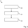
- FIG. 1 shows a flowchart of a method for determining a residual gas mass in cylinder 1.
- FIG 1 shows a flowchart of a method for determining a residual gas mass in cylinder 1.
- a sensor signal representing exhaust back pressure is received from the high resolution exhaust back pressure sensor.
- the exhaust back pressure sensor is designed to to measure the exhaust back pressure with a high temporal sampling rate.
- the sensor signal thus provides values for the exhaust gas back pressure for a large number of points in time in the working cycle of the internal combustion engine.
- an exhaust gas back pressure is extracted from the sensor signal at a predetermined time during a working cycle of the internal combustion engine in the range from the opening time of the intake valve to the closing time of the exhaust valve.
- the predetermined point in time is a point in time at which the intake valve and the exhaust valve are at least partially open.
- a residual gas mass is calculated at 32 on the basis of the exhaust gas back pressure obtained at the predetermined point in time.
- the calculation is carried out using a fixed, predetermined relationship between the residual gas mass and the exhaust gas back pressure at the predetermined point in time. This allows the cylinder charge to be determined very precisely overall.
Landscapes
- Engineering & Computer Science (AREA)
- Chemical & Material Sciences (AREA)
- Combustion & Propulsion (AREA)
- Mechanical Engineering (AREA)
- General Engineering & Computer Science (AREA)
- Physics & Mathematics (AREA)
- General Physics & Mathematics (AREA)
- Combined Controls Of Internal Combustion Engines (AREA)
- Output Control And Ontrol Of Special Type Engine (AREA)
Description
- Die Erfindung betrifft ein Verfahren und eine Steuervorrichtung zum Bestimmen einer Menge einer Füllungskomponente in einem Zylinder einer Verbrennungskraftmaschine, insbesondere zum Bestimmen einer Restgasmenge in einem Zylinder einer Verbrennungskraftmaschine eines Kraftfahrzeugs. Weiterhin betrifft die Erfindung ein Kraftfahrzeug mit einer solchen Steuervorrichtung.
- Beim Betrieb von Ottomotoren spielt eine möglichst genaue Erfassung der aktuellen Zylinderluftfüllung eine zentrale Rolle, um die Kraftstoffmasse per Einspritzung möglichst exakt im stöchiometrischen Verhältnis abzusetzen, dass ein Lambdawert den Wert eins annimmt, und somit die Schadstoffemissionen zu minimieren. Bei Dieselmotoren ist eine genaue Bestimmung der Zylinderfüllung aufgrund der Abgasgesetzgebung ebenso von zunehmender Bedeutung. Im Motorsteuergerät wird daher die Zylinderluftfüllung in der Regel aus einem gemessenen oder modellierten Saugrohrdruck, einem gemessenen oder modellierten Abgasgegendruck und Modellen für den Restgasanteil im Zylinder berechnet. Des Weiteren gehen in die Berechnung der Zylinderluftfüllung die aktuellen Positionen füllungsbeeinflussender Aktuatoren, beispielsweise die Positionen der Einlass- und Auslassnockenwellen, der Ladungsbewegungsklappen, der Ventilhübe und andere Positionen, sowie Ansaugluft- und Abgastemperaturen ein. Ein weiterer wichtiger Parameter in der Berechnung der aktuellen Zylinderfüllung ist der Abgasgegendruck direkt nach den Auslassventilen, da dieser einen maßgeblichen Einfluss auf die Restgasrate im Brennraum hat. Dabei wird bei sensorbasierten Verfahren typischerweise der über ein Arbeitsspielsegment gemittelte Abgasgegendruck betrachtet.
- Wird ein aufgeladener Ottomotor in Betriebspunkten mit Nockenwellenüberschneidung betrieben, so ist der Abgasgegendruck starken kurbelwinkelabhängigen Schwankungen unterworfen. Insbesondere bei niedrigen bis mittleren Drehzahlen kann die Verwendung des gemittelten Abgasgegendrucks zu fehlerhaften Berechnungen der Zylinderluftfüllung führen. Parametrisierte Modelle für den Zusammenhang zwischen Zylinderluftfüllung und gemittelten Abgasgegendruck zeigen in einigen Betriebsbereichen ein extrem nichtlineares Verhalten, welches vor allem auch in Hinblick auf Sensortoleranzen zu erheblichen Ungenauigkeiten führen kann.
- Die
DE 10 2006 032 366 A1 beschreibt ein Verfahren zum Bestimmen einer Frischluftmasse in einem Zylinder auf Grundlage einer Abgasmenge, wobei die Abgasmenge aus einem Verhältnis eines Abgasdrucks vor und nach einer Blende, die in einem Abgaskanal hinter einem Auslassventil des Zylinders angeordnet ist, bestimmt wird. Aus der Abgasmenge wird dann die Frischluftmasse bestimmt. Die Genauigkeit der Bestimmung der Frischluftmasse kann in Betriebspunkten mit Nockenwellenüberschneidung wiederum beeinträchtigt sein.US 2003/105575 A1 ,US 2014/230780 A1 undDE 102 13 138 A1 offenbaren ebenfalls eine Bestimmung der Restgasmenge mittels Abgasgegendrucksensor. - Aufgabe der vorliegenden Erfindung ist es, ein Verfahren und eine Steuervorrichtung zum Bestimmen einer Menge einer Restgasmenge in einem Zylinder einer Verbrennungskraftmaschine bereitzustellen, die die oben genannten Nachteile wenigstens teilweise überwinden.
- Diese Aufgabe wird durch das erfindungsgemäße Verfahren zum Bestimmen einer Menge einer Restgasmenge in einem Zylinder nach Anspruch 1 und die erfindungsgemäße Steuervorrichtung zum Bestimmen einer Menge einer Füllungskomponente in einem Zylinder nach Anspruch 4 gelöst.
- Gemäß einem ersten Aspekt betrifft die Erfindung ein Verfahren zum Bestimmen einer Menge einer Restgasmenge in einem Zylinder einer Verbrennungskraftmaschine, wobei der Zylinder über ein Einlassventil mit einer Luftzuführung und über ein Auslassventil mit einer Abgasführung verbunden ist, umfassend:
Erhalten eines Abgasgegendrucks zu einem vorgegebenen Zeitpunkt während eines Arbeitsspiels der Verbrennungskraftmaschine, zu dem das Auslassventil geöffnet ist; und Berechnen der Menge der Restgasmenge zu dem vorgegebenen Zeitpunkt auf Grundlage des erhaltenen Abgasgegendrucks. - Gemäß einem zweiten Aspekt betrifft die Erfindung eine Steuervorrichtung zum Bestimmen einer Menge einer Restgasmenge in einem Zylinder einer Verbrennungskraftmaschine, wobei die Steuervorrichtung dazu ausgelegt ist, ein Verfahren zum Bestimmen einer Menge einer Restgasmenge in einem Zylinder nach dem ersten Aspekt auszuführen.
- Weitere vorteilhafte Ausgestaltungen der Erfindung ergeben sich aus den Unteransprüchen und der folgenden Beschreibung bevorzugter Ausführungsbeispiele der vorliegenden Erfindung.
- Die vorliegende Erfindung betrifft ein Verfahren zum Bestimmen einer Restgasmenge, in einem Zylinder einer Verbrennungskraftmaschine, insbesondere einer Verbrennungskraftmaschine eines Kraftfahrzeugs mit den Merkmalen des Verfahrens gemäß Anspruch 1 sowie der Steuervorrichtung gemäß Anspruch 4.
- Die Verbrennungskraftmaschine ist derart ausgebildet, dass der Zylinder über ein Einlassventil mit einer Luftzuführung, insbesondere einem Saugrohr, und über ein Auslassventil mit einer Abgasführung, insbesondere einem Abgaskrümmer, verbunden ist. Die Verbrennungskraftmaschine kann ein Ottomotor oder ein Dieselmotor sein.
- Gemäß dem Verfahren wird ein Abgasgegendruck zu einem vorgegebenen Zeitpunkt während eines Arbeitsspiels der Verbrennungskraftmaschine, zu dem das Einlassventil und das Auslassventil teilweise geöffnet sind, empfangen und auf Grundlage des erhaltenen Abgasgegendrucks die Restgasmenge zu dem vorgegebenen Zeitpunkt berechnet. Der Abgasgegendruck zu dem vorgegebenen Zeitpunkt wird in der Abgasführung benachbart zu dem Auslassventil von einem hochauflösenden Abgasgegendrucksensor gemesser, wobei die Abtastrate zwischen 0,5kHz bis 3000kHz liegt.
- Mit dem beschriebenen Verfahren lässt sich die Restgasmenge und damit die Zylinderfüllung insgesamt sehr exakt bestimmen.
- Das Arbeitsspiel (auch als Arbeitszyklus bezeichnet) kann die Schritte Ansaugen, Verdichten, Arbeiten, Ausstoßen umfassen. Ein Arbeitsspiel der Verbrennungskraftmaschine erstreckt sich bei einem Viertaktmotor beispielsweise über zwei Kurbelwellenumdrehungen.
- In manchen Ausführungsbeispielen kann der vorgegebene Zeitpunkt während des Arbeitsspiels der Verbrennungskraftmaschine ein Zeitpunkt sein, zu dem das Einlassventil geöffnet ist. Der vorgegebene Zeitpunkt ist ein Zeitpunkt während einer Ventilüberschneidung (auch als Nockenwellenüberschneidung bezeichnet) sein. Während der Ventilüberschneidung ist sowohl das Einlassventil als auch das Auslassventil geöffnet. Eine Ventilüberschneidung kann beispielsweise während des Ausstoßens und/oder des Ansaugens vorgesehen sein.
- Zu dem vorgegebenen Zeitpunkt, zu dem das Einlassventil geöffnet ist, ist das Einlassventil teilweise geöffnet.
- Vorzugsweise kann ein Ventilhub des Einlassventils zu dem vorgegebenen Zeitpunkt 0,1mm oder mehr betragen, insbesondere im Bereich von 0,2mm bis 0,5mm liegen oder größer sein.
- Der vorgegebene Zeitpunkt kann beispielsweise der Zeitpunkt sein, zu dem der Ventilhub des Einlassventils zwischen 0,2mm und 0,5mm liegt und das Auslassventil teilweise geöffnet ist. Alternativ kann das Einlassventil teilweise geöffnet sein und ein Ventilhub des Auslassventils zwischen 0,2mm und 0,5mm liegen. Weiter alternativ kann der vorgegebene Zeitpunkt zwischen einem Zeitpunkt, zu dem das Einlassventil öffnet, und einem Zeitpunkt, zu dem das Auslassventil schließt, liegen, insbesondere mittig zwischen diesen beiden Zeitpunkten liegen.
- Der Abgasgegendruck zu dem vorgegebenen Zeitpunkt kann gemessen sein oder auf Grundlage von Messdaten berechnet sein. Die Messdaten können zu verschiedenen Zeitpunkten während des einen Arbeitsspiels gemessen sein, zu denen sowohl das Einlassventil als auch das Auslassventil teilweise geöffnet sind, und der Abgasgegendruck kann beispielsweise durch Bildung eines Mittelwerts berechnet sein.
- Da der Abgasgegendruck während der Ventilüberschneidung entscheidend ist für die Zylinderluftfüllung des Zylinders sowie die Restgasmenge und nicht die gemittelten Druckverläufe, ermöglicht das beschriebene Verfahren eine sehr exakte Berechnung der Zylinderluftfüllung bei Betriebspunkten mit hoher NockenwellenÜberschneidung und bei hohen Abgasgegendrücken. Aber auch für andere Betriebspunkte, die eine geringere oder, nicht erfindungsgemäß, keine Nockenwellenüberschneidung zeigen, ist eine sehr exakte Berechnung der Zylinderluftfüllung sowie der Restgasmasse möglich.
- Die Menge der Füllungskomponente umfasst erfindungsgemäß eine Restgasmenge, insbesondere eine Restgasmasse, nicht erfindungsgemäß eine Frischluftmenge, insbesondere eine Frischluftmasse, und/oder nicht erfindungsgemäß eine Spülluftmenge, insbesondere eine Spülluftmasse.
- Die Restgasmenge ist vorzugsweise eine Menge an Abgas, die während des Ausstoßens in dem Zylinder verbleibt. Die Frischluftmenge ist vorzugsweise eine Menge an Frischluft, die während des Ansaugens in den Zylinder gelangt und in diesem verbleibt. Die Spülluftmenge ist vorzugsweise eine Menge an Frischluft, die während des Ansaugens während der Ventilüberschneidung in den Zylinder gelangt und diesen über das Auslassventil wieder verlässt.
- Da der Abgasgegendruck während der Ventilüberschneidung insbesondere das Ausmaß einer Restgasüberströmung oder Restgasausspülung beeinflusst, kann mit dem beschriebenen Verfahren die Restgasmenge, insbesondere die Restgasmasse, besonders genau festgestellt werden.
- In manchen Ausführungsbeispielen kann zwischen dem Abgasgegendruck zu dem vorgegebenen Zeitpunkt und der Restgasmenge ein vorgegebener Zusammenhang bestehen. Dieser kann über einen vorgegebenen Abgasgegendruckbereich im Wesentlichen konstant oder zumindest eindeutig definiert sein.
- Die Ausnutzung des Zusammenhangs zwischen der Restgasmenge, und dem Abgasgegendruck zu dem vorgegebenen Zeitpunkt, zu dem das Auslassventil und das Einlassventil teilweise geöffnet sind, macht das beschriebene Verfahren robust gegen systematische und stochastische Fehler in einer Messwerterfassung eines Abgasgegendrucksensors. Der feste vorgegebene Zusammenhang zwischen der Restgasmenge, und dem Abgasgegendruck zu dem Zeitpunkt, zu dem das Auslassventil und das Einlassventil teilweise geöffnet sind, reduziert zudem bei der Berechnung der Luftmasse in einem Motorsteuergerät Rechenaufwand und Speicherbedarf.
- Beim Bestimmen der Restgasmenge kann weiterhin ein Saugrohrdruck berücksichtigt werden. Der Saugrohrdruck kann in der Luftzuführung, vorzugsweise benachbart zu dem Einlassventil, von einem Drucksensor gemessen sein. Beispielsweise kann ein Verhältnis zwischen dem Saugrohrdruck und dem Abgasgegendruck zu dem vorgegebenen Zeitpunkt, insbesondere während der Ventilüberschneidung, bestimmt werden. Auf Grundlage dieses Verhältnisses zwischen dem Saugrohrdruck und dem Abgasgegendruck kann dann die Menge der Restgasmenge berechnet werden.
- Da das Verhältnis zwischen dem Saugrohrdruck und dem Abgasgegendruck während der Ventilüberschneidung entscheidend ist für das Ausmaß der Restgasüberströmung oder Restgasausspülung, kann die Restgasmenge mit dem erfindungsgemäßen Verfahren sehr genau bestimmt werden.
- In manchen Ausführungsbeispielen kann die Restgasmenge zusätzlich zu dem Abgasgegendruck und gegebenenfalls dem Saugrohrdruck ferner von einem oder mehreren Zustandsparametern der Verbrennungskraftmaschine abhängig sein. Die Zustandsparameter können eine Drehzahl der Verbrennungskraftmaschine, eine Position eines oder mehrerer Ventiltriebsteller, beispielsweise eine Einlassnockenwellenphase, eine Auslassnockenwellenphase oder eine andere Position, und/oder eine oder mehrere Temperaturen, beispielsweise eine Ansauglufttemperatur, eine Motortemperatur oder eine Abgastemperatur, umfassen. Durch die Berücksichtigung des einen oder mehrerer Zustandsparameter lässt sich die Genauigkeit der Bestimmung der Menge der Füllungskomponente weiter verbessern.
- In manchen Ausführungsbeispielen kann die Menge der Füllungskomponente von einem oder mehreren Konstruktionsparametern der Verbrennungskraftmaschine, zu Beispiel von einem Volumen des Zylinders der Verbrennungskraftmaschine, abhängig sein. Dadurch lässt sich die Genauigkeit der Bestimmung der Menge der Füllungskomponente weiter verbessern.
- Erfindungsgemäß umfasst das erfindungsgemäße Verfahren weiterhin das Empfangen eines Sensorsignals mit einer hohen zeitlichen Abtastrate von einem hochauflösenden Abgasgegendrucksensor, wobei das Sensorsignal den Abgasgegendruck repräsentiert. Die Abtastrate liegt im Bereich von 0,5 kHz bis 3000 kHz, insbesondere im Bereich von 1 kHz bis 1000 kHz. Der Abgasgegendruck zu dem vorgegebenen Zeitpunkt wird dann aus dem Sensorsignal extrahiert.
- Durch die Verwendung des Abgasgegendrucksensors in Verbindung mit einer hohen zeitlichen Abtastrate des Sensors wird der momentane Abgasgegendruck zu verschiedenen Zeitpunkten während eines Arbeitsspiels erfasst. Auf diese Weise wird der Abgasgegendruck zu dem Zeitpunkt, zu dem das Auslassventil und das Einlassventil teilweise geöffnet sind, bestimmt. Mithilfe dieses Messwertes kann bei Kenntnis des entsprechenden Zylindervolumens und der Abgastemperatur die Restgasmenge errechnet werden.
- Das oben beschriebene Verfahren ermöglicht eine sehr exakte Bestimmung der
- Zylinderluftfüllung bzw. der Menge der Füllungskomponente, die erfindungsgemäß die Restgasmenge ist, insbesondere bei Betriebspunkten mit hoher Nockenwellenüberschneidung und bei hohen Abgasgegendrücken. Die Ausnutzung des vorgegebenen Zusammenhangs zwischen der Menge der Füllungskomponente, beispielsweise einer Zylinderluftmasse, und dem Abgasgegendruck zu dem vorgegebenen Zeitpunkt, insbesondere zu dem Zeitpunkt, zu dem das Einlassventil sowie das Auslassventil teilweise geöffnet sind, macht dieses Verfahren zudem robust gegen systematische und stochastische Fehler in der
- Messwerterfassung des Abgasgegendrucksensors. Der feste vorgegebene Zusammenhang zwischen Zylinderluftmasse und Abgasgegendruck zu dem vorgegebenen Zeitpunkt reduziert zudem bei der Berechnung der Zylinderluftmasse im Motorsteuergerät Rechenaufwand und Speicherbedarf.
- Die vorliegende Erfindung betrifft weiterhin eine Steuervorrichtung zum Bestimmen einer Menge einer Füllungskomponente in einem Zylinder einer Verbrennungskraftmaschine, wobei der Zylinder über ein Einlassventil mit einer Luftzuführung und über ein Auslassventil mit einer Abgasführung verbunden ist, mit den Merkmalen des Anspruchs 4. Die Steuervorrichtung ist dazu ausgelegt, einen Abgasgegendruck zu einem vorgegebenen Zeitpunkt während eines Arbeitsspiels der Verbrennungskraftmaschine, zu dem das Einlassventil und das Auslassventil teilweise geöffnet sind, zu empfangen und auf Grundlage des erhaltenen Abgasgegendrucks die Restgasmenge zu dem vorgegebenen Zeitpunkt zu berechnen. Die Steuervorrichtung ist insbesondere dazu ausgelegt, ein Verfahren zum Bestimmen einer Menge einer Füllungskomponente, die erfindungsgemäß eine Restgasmenge ist, in einem Zylinder, wie es voranstehend beschrieben ist, auszuführen.
- Die Steuervorrichtung kann einen Prozessor, beispielsweise einen Mikroprozessor, aufweisen, der dazu ausgebildet ist, das beschriebene Verfahren zum Bestimmen einer Menge einer Füllungskomponente in einem Zylinder auszuführen. Die Steuervorrichtung kann weiterhin einen Datenspeicher aufweisen, in dem vorzugsweise ein Programm hinterlegt ist, das Anweisungen für den Prozessor enthält, um diesen entsprechend dem beschriebenen Verfahren zu steuern. In dem Datenspeicher können zudem der vorgegebene Zusammenhang und/oder vorgegebene Parameter zum Durchführen des beschriebenen Verfahrens, beispielsweise das Zylindervolumen, hinterlegt sein.
- Die Steuervorrichtung kann eine Reihe von Signaleingängen und Signalausgängen aufweisen. Über die Signaleingänge können beispielsweise der Abgasgegendruck, der Saugrohrdruck, die Zustandsparameter der Verbrennungskraftmaschine und/oder andere Signale empfangen werden. Über die Signalausgänge kann insbesondere die Menge der Füllungskomponente ausgegeben werden.
- Die Steuervorrichtung kann in eine Motorsteuerung des Kraftfahrzeugs integriert sein. Alternativ kann die Steuervorrichtung als eine separate Einheit ausgebildet sein.
- In manchen Ausführungsbeispielen kann die Steuervorrichtung einen Abgasgegendrucksensor umfassen oder mit einem Abgasgegendrucksensor, beispielsweise über einen der Signaleingänge, verbindbar sein. Der Abgasgegendrucksensor ist dabei dazu ausgebildet, ein Sensorsignal mit einer hohen zeitlichen Abtastrate, das den Abgasgegenruck repräsentiert, auszugeben. Die Steuervorrichtung wiederum ist dazu ausgelegt, den Abgasgegendruck zu dem vorgegebenen Zeitpunkt aus dem Sensorsignal zu extrahieren.
- Die vorliegende Erfindung betrifft weiterhin ein Kraftfahrzeug mit einer Verbrennungskraftmaschine und einer Steuervorrichtung zum Bestimmen einer Menge einer Füllungskomponente in einem Zylinder der Verbrennungskraftmaschine, wie sie voranstehend beschrieben wurde. Die Verbrennungskraftmaschine weist einen Zylinder, ein Einlassventil, über das der Zylinder mit einer Luftzuführung verbunden ist, und ein Auslassventil, über das der Zylinder mit einer Abgasführung verbunden ist, auf. Die Verbrennungskraftmaschine kann ein Ottomotor sein, der vorzugsweise so gesteuert ist, dass eine Ventilüberschneidung, insbesondere eine hohe Ventilüberschneidung, auftritt. Die Verbrennungskraftmaschine kann ein Dieselmotor sein, der vorzugsweise mit einer erweiterten Variabilität im Ventiltrieb betreibbar ist und/oder eine interne Abgasrückführung nutzt.
- Ausführungsbeispiele der Erfindung werden nun beispielhaft und unter Bezugnahme auf die beigefügten Zeichnungen beschrieben. Es zeigen:
- Fig. 1
- schematisch ein Ausführungsbeispiel einer Verbrennungskraftmaschine;
- Fig. 2
- einen Ausschnitt eines Arbeitszyklus der Verbrennungskraftmaschine; und
- Fig. 3
- ein Flussdiagramm eines erfindungsgemäßen Verfahrens zum Bestimmen einer Menge einer Füllungskomponente in einem Zylinder der Verbrennungskraftmaschine aus
Fig. 1 . - Ein Ausführungsbeispiel eines Zylinders 1 einer Verbrennungskraftmaschine ist in
Fig. 1 schematisch dargestellt. Der Zylinder 1 hat einen Brennraum 10, in dem die Verbrennung von Kraftstoff stattfindet, der über ein Einspritzventil 11eingespritzt wird. Der Zylinder 1 ist über ein Einlassventil 12 mit einem Saugrohr 13 gekoppelt, aus dem durch das Einlassventil 12 Frischluft in den Brennraum 10 gelangt. Außerdem ist der Zylinder 1 über ein Auslassventil 14 mit einem Abgaskrümmer 15 gekoppelt ist, durch das Abgas bzw. Restgas aus dem Brennraum 10 in den Abgaskrümmer 15 geleitet wird. Ferner ist ein Zylinderkolben 16 vorhanden, der von einer Kurbelwelle (nicht dargestellt) angetrieben wird. In dem Abgaskrümmer 15 direkt hinter dem Auslassventil 14 ist ein Abgasgegendrucksensor 2 angeordnet, der dazu ausgebildet ist, einen Abgasgegendruck mit hoher zeitlicher Abtastrate zu detektieren. - In der
Fig. 1 ist der Zylinder 1 zu einem Zeitpunkt, in dem das Einlassventil 12 und das Auslassventil 14 geöffnet sind und eine Ventilüberschneidung vorliegt, dargestellt. -
Fig. 2 zeigt einen Ausschnitt eines Arbeitszyklus der Verbrennungskraftmaschine, der einen Öffnungszeitpunkt ÖE und einen Schließzeitpunkt SE des Einlassventils 12 und einen Schließzeitpunkt SA des Auslassventils 14 während des Ansaugens verdeutlicht. Der Arbeitszyklus der Verbrennungskraftmaschine umfasst das Ansaugen von Frischluft in den Zylinder, das Verdichten der Zylinderfüllung in dem Zylinder, das Arbeiten bzw. das Verbrennen von Kraftstoff und das Ausstoßen des Abgases bzw. Restgases aus dem Zylinder. - In
Fig. 2 ist ein Kreissektor gezeigt, auf dem ein oberer Totpunkt OT, an dem sich der Kolben 16 der Verbrennungskraftmaschine in einer Position befindet, in der das Zylindervolumen minimal ist, und ein unterer Totpunkt UT, an dem sich der Kolben der Verbrennungskraftmaschine in einer Position befindet, in der das Zylindervolumen maximal ist, angedeutet ist. - In einem Bereich zwischen dem oberen Totpunkt OT und dem unteren Totpunkt UT entlang der rechten Kreishälfte erfolgt das Ansaugen. Wie in
Fig. 2 links vom oberen Totpunkt OT gezeigt, wird das Einlassventil der Verbrennungskraftmaschine zu einem Öffnungszeitpunkt ÖE geöffnet, bevor der Kolben den oberen Totpunkt erreicht. Kurz nachdem der Kolben 16 den oberen Totpunkt OT durchlaufen hat, liegt ein Schließzeitpunkt SA des Auslassventils 14. Kurz bevor der Kolben den unteren Totpunkt UT erreicht, schließt auch das Einlassventil 12, was als Schließzeitpunkt SE inFig. 3 gezeigt ist. - Der Abgasgegendrucksensor 2 ist mit einer Motorsteuerung (nicht dargestellt) verbunden, die dazu ausgebildet ist, ein Verfahren zum Bestimmen einer Restgasmasse in dem Zylinder, wie es mit Bezug auf
Fig. 3 weiter unten beschrieben wird, auszuführen. Auf Grundlage der bestimmten Restgasmasse kann die Motorsteuerung dann das Einspritzventil 11 steuern. -
Fig. 3 zeigt ein Flussdiagramm eines Verfahrens zum Bestimmen einer Restgasmasse in dem Zylinder 1 ausFig. 1 . - Bei 30 wird von dem hochauflösenden Abgasgegendrucksensor ein Sensorsignal empfangen, das den Abgasgegendruck repräsentiert. Der Abgasgegendrucksensor ist dazu ausgebildet, den Abgasgegendruck mit einer hohen zeitlichen Abtastrate zu messen. Das Sensorsignal stellt somit für eine Vielzahl an Zeitpunkten des Arbeitszyklus der Verbrennungskraftmaschine Werte für den Abgasgegendruck zur Verfügung.
- Bei 31 wird zu einem vorgegebenen Zeitpunkt während eines Arbeitsspiels der Verbrennungskraftmaschine im Bereich von dem Öffnungszeitpunkt des Einlassventils bis zu dem Schließzeitpunkt des Auslassventils aus dem Sensorsignal ein Abgasgegendruck extrahiert. Der vorgegebene Zeitpunkt ist ein Zeitpunkt, zu dem das Einlassventil und das Auslassventil zumindest teilweise geöffnet sind.
- Bei 32 wird auf Grundlage des erhaltenen Abgasgegendrucks zu dem vorgegebenen Zeitpunkt eine Restgasmasse berechnet. Die Berechnung erfolgt mit Hilfe eines festen vorgegebenen Zusammenhangs zwischen der Restgasmasse und dem Abgasgegendruck zu dem vorgegebenen Zeitpunkt. Damit lässt sich insgesamt die Zylinderfüllung sehr exakt bestimmen.
-
- 1
- Zylinder einer Verbrennungskraftmaschine
- 10
- Brennraum
- 11
- Einspritzventil
- 12
- Einlassventil
- 13
- Saugrohr
- 14
- Auslassventil
- 15
- Abgaskrümmer
- 16
- Zylinderkolben
- 2
- Abgasgegendrucksensor
- 3
- Verfahren zum Bestimmen einer Restgasmasse in dem Zylinder
- 30
- Empfangen eines Sensorsignals von dem Abgasgegendrucksensor
- 31
- Erhalten eines Abgasgegendrucks zu dem vorgegebenen Zeitpunkt
- 32
- Berechnen der Restgasmasse aus dem Abgasgegendruck
- OT
- oberer Totpunkt
- UT
- unterer Totpunkt
- ÖE
- Öffnungszeitpunkt des Einlassventils
- SE
- Schließzeitpunkt des Einlassventils
- SA
- Schließzeitpunkt des Auslassventils
Claims (5)
- Verfahren zum Bestimmen einer Restgasmenge in einem Zylinder (1) einer Verbrennungskraftmaschine, wobei der Zylinder (1) über ein Einlassventil (12) mit einer Luftzuführung (13) und über ein Auslassventil (14) mit einer Abgasführung (15) verbunden ist, umfassend:Erhalten (31) eines Abgasgegendrucks zu einem vorgegebenen Zeitpunkt während eines Arbeitsspiels der Verbrennungskraftmaschine, zu dem das Einlassventil (12) teilweise geöffnet ist und das Auslassventil (14) teilweise geöffnet ist, wobei ein Sensorsignal mit einer hohen zeitlichen Abtastrate, das den Abgasgegendruck repräsentiert, von einem hochauflösenden Abgasgegendrucksensor (2), der in der Abgasführung benachbart zum Auslassventil angeordnet ist, empfangen wird, wobei die Abtastrate im Bereich von mit 0,5 kHz bis 3000kHz liegt, und der Abgasgegendruck zu dem vorgegebenen Zeitpunkt aus dem Sensorsignal extrahiert wird; undBerechnen (32) der Restgasmenge zu dem vorgegebenen Zeitpunkt in Abhängigkeit des erhaltenen Abgasgegendrucks.
- Verfahren nach dem vorhergehenden Anspruch, wobei die Restgasmenge ferner von einem Zustandsparameter der Verbrennungskraftmaschine abhängig ist.
- Verfahren nach einem der vorhergehenden Ansprüche, wobei die Restgasmenge ferner von einem Konstruktionsparameter der Verbrennungskraftmaschine abhängig ist.
- Steuervorrichtung zum Bestimmen einer Restgasmenge in einem Zylinder (1) einer Verbrennungskraftmaschine, wobei die Steuervorrichtung einen Abgasgegendrucksensor (2) umfasst oder mit einem Abgasgegendrucksensor (2) verbindbar ist, der dazu ausgebildet ist, ein Sensorsignal mit einer hohen zeitlichen Abtastrate auszugeben, das den Abgasgegenruck repräsentiert, und der in der Abgasführung benachbart zum Auslassventil angeordnet ist, wobei die Abtastrate im Bereich von mit 0,5 kHz bis 3000kHz liegt, und wobei die Steuervorrichtung dazu ausgelegt ist, ein Verfahren zum Bestimmen einer Restgasmenge in einem Zylinder (1) nach einem der vorhergehenden Ansprüche auszuführen.
- Kraftfahrzeug mit einer Verbrennungskraftmaschine, die einen Zylinder (1), ein Einlassventil (12), über das der Zylinder (1) mit einer Luftzuführung (13) verbunden ist, und ein Auslassventil (14), über das der Zylinder (1) mit einer Abgasführung verbunden ist, umfasst, und mit einer Steuervorrichtung (2) zum Bestimmen einer Restgasmenge in dem Zylinder (1) der Verbrennungskraftmaschine nach dem vorhergehenden Anspruch.
Applications Claiming Priority (2)
| Application Number | Priority Date | Filing Date | Title |
|---|---|---|---|
| DE102016204539.3A DE102016204539A1 (de) | 2016-03-18 | 2016-03-18 | Verfahren und Steuervorrichtung zum Bestimmen einer Menge einer Füllungskomponente in einem Zylinder einer Verbrennungskraftmaschine |
| PCT/EP2017/052494 WO2017157580A1 (de) | 2016-03-18 | 2017-02-06 | Verfahren und steuervorrichtung zum bestimmen einer menge einer füllungskomponente in einem zylinder einer verbrennungskraftmaschine |
Publications (2)
| Publication Number | Publication Date |
|---|---|
| EP3430252A1 EP3430252A1 (de) | 2019-01-23 |
| EP3430252B1 true EP3430252B1 (de) | 2023-01-11 |
Family
ID=57963234
Family Applications (1)
| Application Number | Title | Priority Date | Filing Date |
|---|---|---|---|
| EP17703149.9A Active EP3430252B1 (de) | 2016-03-18 | 2017-02-06 | Verfahren und steuervorrichtung zum bestimmen einer menge einer füllungskomponente in einem zylinder einer verbrennungskraftmaschine |
Country Status (5)
| Country | Link |
|---|---|
| US (1) | US10774757B2 (de) |
| EP (1) | EP3430252B1 (de) |
| CN (1) | CN108779728B (de) |
| DE (1) | DE102016204539A1 (de) |
| WO (1) | WO2017157580A1 (de) |
Families Citing this family (2)
| Publication number | Priority date | Publication date | Assignee | Title |
|---|---|---|---|---|
| DE102019212932A1 (de) * | 2019-08-28 | 2021-03-04 | Volkswagen Aktiengesellschaft | Verfahren zur Zylindergleichstellung einer Verbrennungskraftmaschine |
| DE102019213092A1 (de) * | 2019-08-30 | 2021-03-04 | Volkswagen Aktiengesellschaft | Verfahren zur Diagnostik von Verbrennungsaussetzern einer Verbrennungskraftmaschine |
Family Cites Families (20)
| Publication number | Priority date | Publication date | Assignee | Title |
|---|---|---|---|---|
| BR9604813A (pt) * | 1995-04-10 | 1998-06-09 | Siemens Ag | Método para detminação do fluxo de massa de ar dentro de cilindros de um motor de combustão interna com ajuda de um modelo |
| DE59700375D1 (de) * | 1996-03-15 | 1999-09-30 | Siemens Ag | Verfahren zum modellgestützten bestimmen der in die zylinder einer brennkraftmaschine einströmenden frischluftmasse bei externer abgasrückführung |
| DE19740917B4 (de) | 1997-04-01 | 2008-11-27 | Robert Bosch Gmbh | Verfahren und Vorrichtung zur Bestimmung der Gastemperatur in einem Verbrennungsmotor |
| ITBO20010076A1 (it) | 2001-02-13 | 2002-08-13 | Magneti Marelli Spa | Metodo per la stima del reperimento di un cilindro in un motore a combustione interna |
| DE10213138B4 (de) * | 2001-11-20 | 2017-02-16 | Robert Bosch Gmbh | Verfahren, Computerprogramm, Steuer- und/oder Regelgerät zum Betreiben einer Brennkraftmaschine |
| US6711489B2 (en) * | 2001-12-05 | 2004-03-23 | Visteon Global Technologies, Inc. | Method for estimating engine cylinder variables using second order sliding modes |
| DE102004030604B3 (de) | 2004-06-24 | 2006-02-09 | Siemens Ag | Verfahren zur Bestimmung der Luftmasse in einem Zylinder |
| DE102005055952A1 (de) * | 2005-11-24 | 2007-05-31 | Robert Bosch Gmbh | Verfahren zum Betreiben einer Brennkraftmaschine |
| DE602006003524D1 (de) | 2006-03-02 | 2008-12-18 | Fiat Ricerche | Brennkraftmaschine mit Mitteln zur Bestimmung Frischluftmasse, und dazugehörige Methode zur Bestimmung |
| DE102006032366A1 (de) | 2006-07-11 | 2008-01-17 | Iav Gmbh Ingenieurgesellschaft Auto Und Verkehr | Verfahren zum Betrieb einer Verbrennungskraftmaschine |
| US7798126B2 (en) * | 2007-08-17 | 2010-09-21 | Gm Global Technology Operations, Inc. | Method for controlling cylinder charge in a homogeneous charge compression ignition engine |
| CN101892914B (zh) * | 2010-07-14 | 2015-08-19 | 中国第一汽车集团公司 | 基于模型的发动机瞬态进气量预估方法 |
| US8532910B2 (en) * | 2011-05-17 | 2013-09-10 | GM Global Technology Operations LLC | Method and apparatus to determine a cylinder air charge for an internal combustion engine |
| US8977470B2 (en) * | 2011-09-13 | 2015-03-10 | Ford Global Technologies, Llc | Method and system for sampling intake manifold pressure |
| JP5944249B2 (ja) * | 2012-07-06 | 2016-07-05 | 本田技研工業株式会社 | 内燃機関の内部egr量算出装置 |
| JP5844227B2 (ja) * | 2012-07-17 | 2016-01-13 | 本田技研工業株式会社 | 内燃機関の掃気ガス量算出装置および内部egr量算出装置 |
| EP2708726B1 (de) | 2012-09-17 | 2021-03-17 | Magneti Marelli S.p.A. | Verfahren zur Schätzung der Abgasdurchflussrate für einen Verbrennungsmotor |
| DE102012221311B4 (de) * | 2012-11-22 | 2014-07-10 | Continental Automotive Gmbh | Verfahren zur Frischlufterfassung durch Auswertung eines Zylinderinnendrucksignals |
| EP2959140A2 (de) * | 2013-02-20 | 2015-12-30 | Robert Bosch GmbH | Echtzeit-restmassenschätzung mit adaptiver skalierung |
| US10337416B2 (en) * | 2013-11-21 | 2019-07-02 | Ford Global Technologies, Llc | Methods and systems for determining engine misfire |
-
2016
- 2016-03-18 DE DE102016204539.3A patent/DE102016204539A1/de not_active Withdrawn
-
2017
- 2017-02-06 CN CN201780018195.4A patent/CN108779728B/zh active Active
- 2017-02-06 WO PCT/EP2017/052494 patent/WO2017157580A1/de not_active Ceased
- 2017-02-06 EP EP17703149.9A patent/EP3430252B1/de active Active
-
2018
- 2018-09-18 US US16/134,036 patent/US10774757B2/en active Active
Also Published As
| Publication number | Publication date |
|---|---|
| WO2017157580A1 (de) | 2017-09-21 |
| DE102016204539A1 (de) | 2017-09-21 |
| US10774757B2 (en) | 2020-09-15 |
| CN108779728A (zh) | 2018-11-09 |
| EP3430252A1 (de) | 2019-01-23 |
| US20190017450A1 (en) | 2019-01-17 |
| CN108779728B (zh) | 2022-05-13 |
Similar Documents
| Publication | Publication Date | Title |
|---|---|---|
| DE102007043440B3 (de) | Verfahren zum Ermitteln einer in einem Zylinder einer Brennkraftmaschine eingefangenen Luftmasse | |
| EP3308007B1 (de) | Luftfüllungsbestimmung, motorsteuergerät und verbrennungskraftmaschine | |
| WO2006069853A1 (de) | Verfahren zum betreiben einer brennkraftmaschine | |
| DE102013214039A1 (de) | Spülgasmenge-Berechnungseinrichtung und Interne-AGR-Menge-Berechnungseinrichtung für Verbrennungsmotor | |
| DE102007035314A1 (de) | Verfahren und Vorrichtung zum Betreiben einer Brennkraftmaschine | |
| EP3786436B1 (de) | Verfahren zur diagnostik von verbrennungsaussetzern einer verbrennungskraftmaschine | |
| EP3507475A1 (de) | Verfahren, steuervorrichtung und system zum erkennen einer abweichung eines tatsächlichen betätigungszeitpunkts eines gaswechselventils einer verbrennungskraftmaschine von einem vorgegebenen betätigungszeitpunkt | |
| DE102013212988A1 (de) | Interne-AGR-Menge-Berechnungseinrichtung für Verbrennungsmotor | |
| DE102006009920A1 (de) | Bestimmung zylinderindividueller Korrekturwerte der Einspritzmenge einer Brennkraftmaschine | |
| DE10254475B3 (de) | Verfahren zum Ermitteln der Frischluft-, Restgas- und Gesamtgasmasse in einem Zylinder einer Brennkraftmaschine | |
| DE102008032935A1 (de) | Verfahren zum Berechnen eines Brennraumdruckes in Echtzeit | |
| DE102006021091B3 (de) | Verfahren und Vorrichtung zur Diagnose der Wirksamkeit eines Abgaskatalysators | |
| DE102008043315A1 (de) | Verfahren zum Betreiben einer Brennkraftmaschine und Steuer- und/oder Regeleinrichtung für eine Brennkraftmaschine | |
| DE102007063102A1 (de) | Verfahren zur Erfassung eines periodisch pulsierenden Betriebsparameters | |
| DE10356713B4 (de) | Verfahren zur Regelung bzw. Steuerung einer in einem Kreisprozess arbeitenden Brennkraftmaschine | |
| DE102010046491A1 (de) | Verfahren zum Bestimmen einer Schadstoffemission im Brennraum eines Dieselmotors | |
| DE102015224790A1 (de) | Verfahren zum Betreiben einer Brennkraftmaschine | |
| WO2017157580A1 (de) | Verfahren und steuervorrichtung zum bestimmen einer menge einer füllungskomponente in einem zylinder einer verbrennungskraftmaschine | |
| DE102016218687B4 (de) | Verfahren zur Erkennung eines Beladungsgrades eines Partikelfilters | |
| DE102005035239A1 (de) | Vorrichtung und Verfahren zum Betreiben einer Brennkraftmaschine | |
| DE102013212014A1 (de) | Innere-AGR-Menge-Berechnungsvorrichtung für Verbrennungsmotor | |
| DE102009037272A1 (de) | Verfahren zum Betreiben einer Brennkraftmaschine | |
| EP2236798B1 (de) | Verfahren und Vorrichtung zur Diagnose eines variablen Ventiltriebs einer Brennkraftmaschine | |
| EP3786433A1 (de) | Verfahren zur zylindergleichstellung einer verbrennungskraftmaschine | |
| DE102014104543A1 (de) | Verfahren zur Kalibrierung einer Lambda-Sonde |
Legal Events
| Date | Code | Title | Description |
|---|---|---|---|
| STAA | Information on the status of an ep patent application or granted ep patent |
Free format text: STATUS: UNKNOWN |
|
| STAA | Information on the status of an ep patent application or granted ep patent |
Free format text: STATUS: THE INTERNATIONAL PUBLICATION HAS BEEN MADE |
|
| PUAI | Public reference made under article 153(3) epc to a published international application that has entered the european phase |
Free format text: ORIGINAL CODE: 0009012 |
|
| STAA | Information on the status of an ep patent application or granted ep patent |
Free format text: STATUS: REQUEST FOR EXAMINATION WAS MADE |
|
| 17P | Request for examination filed |
Effective date: 20181018 |
|
| AK | Designated contracting states |
Kind code of ref document: A1 Designated state(s): AL AT BE BG CH CY CZ DE DK EE ES FI FR GB GR HR HU IE IS IT LI LT LU LV MC MK MT NL NO PL PT RO RS SE SI SK SM TR |
|
| AX | Request for extension of the european patent |
Extension state: BA ME |
|
| DAV | Request for validation of the european patent (deleted) | ||
| DAX | Request for extension of the european patent (deleted) | ||
| STAA | Information on the status of an ep patent application or granted ep patent |
Free format text: STATUS: EXAMINATION IS IN PROGRESS |
|
| 17Q | First examination report despatched |
Effective date: 20200403 |
|
| GRAP | Despatch of communication of intention to grant a patent |
Free format text: ORIGINAL CODE: EPIDOSNIGR1 |
|
| STAA | Information on the status of an ep patent application or granted ep patent |
Free format text: STATUS: GRANT OF PATENT IS INTENDED |
|
| INTG | Intention to grant announced |
Effective date: 20220812 |
|
| GRAS | Grant fee paid |
Free format text: ORIGINAL CODE: EPIDOSNIGR3 |
|
| GRAA | (expected) grant |
Free format text: ORIGINAL CODE: 0009210 |
|
| STAA | Information on the status of an ep patent application or granted ep patent |
Free format text: STATUS: THE PATENT HAS BEEN GRANTED |
|
| AK | Designated contracting states |
Kind code of ref document: B1 Designated state(s): AL AT BE BG CH CY CZ DE DK EE ES FI FR GB GR HR HU IE IS IT LI LT LU LV MC MK MT NL NO PL PT RO RS SE SI SK SM TR |
|
| REG | Reference to a national code |
Ref country code: GB Ref legal event code: FG4D Free format text: NOT ENGLISH |
|
| REG | Reference to a national code |
Ref country code: CH Ref legal event code: EP |
|
| REG | Reference to a national code |
Ref country code: DE Ref legal event code: R096 Ref document number: 502017014316 Country of ref document: DE |
|
| REG | Reference to a national code |
Ref country code: IE Ref legal event code: FG4D Free format text: LANGUAGE OF EP DOCUMENT: GERMAN |
|
| REG | Reference to a national code |
Ref country code: AT Ref legal event code: REF Ref document number: 1543557 Country of ref document: AT Kind code of ref document: T Effective date: 20230215 |
|
| REG | Reference to a national code |
Ref country code: LT Ref legal event code: MG9D |
|
| REG | Reference to a national code |
Ref country code: NL Ref legal event code: MP Effective date: 20230111 |
|
| P01 | Opt-out of the competence of the unified patent court (upc) registered |
Effective date: 20230523 |
|
| PG25 | Lapsed in a contracting state [announced via postgrant information from national office to epo] |
Ref country code: NL Free format text: LAPSE BECAUSE OF FAILURE TO SUBMIT A TRANSLATION OF THE DESCRIPTION OR TO PAY THE FEE WITHIN THE PRESCRIBED TIME-LIMIT Effective date: 20230111 |
|
| PG25 | Lapsed in a contracting state [announced via postgrant information from national office to epo] |
Ref country code: RS Free format text: LAPSE BECAUSE OF FAILURE TO SUBMIT A TRANSLATION OF THE DESCRIPTION OR TO PAY THE FEE WITHIN THE PRESCRIBED TIME-LIMIT Effective date: 20230111 Ref country code: PT Free format text: LAPSE BECAUSE OF FAILURE TO SUBMIT A TRANSLATION OF THE DESCRIPTION OR TO PAY THE FEE WITHIN THE PRESCRIBED TIME-LIMIT Effective date: 20230511 Ref country code: NO Free format text: LAPSE BECAUSE OF FAILURE TO SUBMIT A TRANSLATION OF THE DESCRIPTION OR TO PAY THE FEE WITHIN THE PRESCRIBED TIME-LIMIT Effective date: 20230411 Ref country code: LV Free format text: LAPSE BECAUSE OF FAILURE TO SUBMIT A TRANSLATION OF THE DESCRIPTION OR TO PAY THE FEE WITHIN THE PRESCRIBED TIME-LIMIT Effective date: 20230111 Ref country code: LT Free format text: LAPSE BECAUSE OF FAILURE TO SUBMIT A TRANSLATION OF THE DESCRIPTION OR TO PAY THE FEE WITHIN THE PRESCRIBED TIME-LIMIT Effective date: 20230111 Ref country code: HR Free format text: LAPSE BECAUSE OF FAILURE TO SUBMIT A TRANSLATION OF THE DESCRIPTION OR TO PAY THE FEE WITHIN THE PRESCRIBED TIME-LIMIT Effective date: 20230111 Ref country code: ES Free format text: LAPSE BECAUSE OF FAILURE TO SUBMIT A TRANSLATION OF THE DESCRIPTION OR TO PAY THE FEE WITHIN THE PRESCRIBED TIME-LIMIT Effective date: 20230111 |
|
| PG25 | Lapsed in a contracting state [announced via postgrant information from national office to epo] |
Ref country code: SE Free format text: LAPSE BECAUSE OF FAILURE TO SUBMIT A TRANSLATION OF THE DESCRIPTION OR TO PAY THE FEE WITHIN THE PRESCRIBED TIME-LIMIT Effective date: 20230111 Ref country code: PL Free format text: LAPSE BECAUSE OF FAILURE TO SUBMIT A TRANSLATION OF THE DESCRIPTION OR TO PAY THE FEE WITHIN THE PRESCRIBED TIME-LIMIT Effective date: 20230111 Ref country code: IS Free format text: LAPSE BECAUSE OF FAILURE TO SUBMIT A TRANSLATION OF THE DESCRIPTION OR TO PAY THE FEE WITHIN THE PRESCRIBED TIME-LIMIT Effective date: 20230511 Ref country code: GR Free format text: LAPSE BECAUSE OF FAILURE TO SUBMIT A TRANSLATION OF THE DESCRIPTION OR TO PAY THE FEE WITHIN THE PRESCRIBED TIME-LIMIT Effective date: 20230412 Ref country code: FI Free format text: LAPSE BECAUSE OF FAILURE TO SUBMIT A TRANSLATION OF THE DESCRIPTION OR TO PAY THE FEE WITHIN THE PRESCRIBED TIME-LIMIT Effective date: 20230111 |
|
| REG | Reference to a national code |
Ref country code: CH Ref legal event code: PL |
|
| REG | Reference to a national code |
Ref country code: DE Ref legal event code: R097 Ref document number: 502017014316 Country of ref document: DE |
|
| REG | Reference to a national code |
Ref country code: BE Ref legal event code: MM Effective date: 20230228 |
|
| PG25 | Lapsed in a contracting state [announced via postgrant information from national office to epo] |
Ref country code: SM Free format text: LAPSE BECAUSE OF FAILURE TO SUBMIT A TRANSLATION OF THE DESCRIPTION OR TO PAY THE FEE WITHIN THE PRESCRIBED TIME-LIMIT Effective date: 20230111 Ref country code: RO Free format text: LAPSE BECAUSE OF FAILURE TO SUBMIT A TRANSLATION OF THE DESCRIPTION OR TO PAY THE FEE WITHIN THE PRESCRIBED TIME-LIMIT Effective date: 20230111 Ref country code: MC Free format text: LAPSE BECAUSE OF FAILURE TO SUBMIT A TRANSLATION OF THE DESCRIPTION OR TO PAY THE FEE WITHIN THE PRESCRIBED TIME-LIMIT Effective date: 20230111 Ref country code: LU Free format text: LAPSE BECAUSE OF NON-PAYMENT OF DUE FEES Effective date: 20230206 Ref country code: LI Free format text: LAPSE BECAUSE OF NON-PAYMENT OF DUE FEES Effective date: 20230228 Ref country code: EE Free format text: LAPSE BECAUSE OF FAILURE TO SUBMIT A TRANSLATION OF THE DESCRIPTION OR TO PAY THE FEE WITHIN THE PRESCRIBED TIME-LIMIT Effective date: 20230111 Ref country code: DK Free format text: LAPSE BECAUSE OF FAILURE TO SUBMIT A TRANSLATION OF THE DESCRIPTION OR TO PAY THE FEE WITHIN THE PRESCRIBED TIME-LIMIT Effective date: 20230111 Ref country code: CZ Free format text: LAPSE BECAUSE OF FAILURE TO SUBMIT A TRANSLATION OF THE DESCRIPTION OR TO PAY THE FEE WITHIN THE PRESCRIBED TIME-LIMIT Effective date: 20230111 Ref country code: CH Free format text: LAPSE BECAUSE OF NON-PAYMENT OF DUE FEES Effective date: 20230228 |
|
| PLBE | No opposition filed within time limit |
Free format text: ORIGINAL CODE: 0009261 |
|
| STAA | Information on the status of an ep patent application or granted ep patent |
Free format text: STATUS: NO OPPOSITION FILED WITHIN TIME LIMIT |
|
| PG25 | Lapsed in a contracting state [announced via postgrant information from national office to epo] |
Ref country code: SK Free format text: LAPSE BECAUSE OF FAILURE TO SUBMIT A TRANSLATION OF THE DESCRIPTION OR TO PAY THE FEE WITHIN THE PRESCRIBED TIME-LIMIT Effective date: 20230111 Ref country code: AL Free format text: LAPSE BECAUSE OF FAILURE TO SUBMIT A TRANSLATION OF THE DESCRIPTION OR TO PAY THE FEE WITHIN THE PRESCRIBED TIME-LIMIT Effective date: 20230111 |
|
| 26N | No opposition filed |
Effective date: 20231012 |
|
| REG | Reference to a national code |
Ref country code: IE Ref legal event code: MM4A |
|
| PG25 | Lapsed in a contracting state [announced via postgrant information from national office to epo] |
Ref country code: SI Free format text: LAPSE BECAUSE OF FAILURE TO SUBMIT A TRANSLATION OF THE DESCRIPTION OR TO PAY THE FEE WITHIN THE PRESCRIBED TIME-LIMIT Effective date: 20230111 Ref country code: IE Free format text: LAPSE BECAUSE OF NON-PAYMENT OF DUE FEES Effective date: 20230206 |
|
| PG25 | Lapsed in a contracting state [announced via postgrant information from national office to epo] |
Ref country code: BE Free format text: LAPSE BECAUSE OF NON-PAYMENT OF DUE FEES Effective date: 20230228 |
|
| REG | Reference to a national code |
Ref country code: AT Ref legal event code: MM01 Ref document number: 1543557 Country of ref document: AT Kind code of ref document: T Effective date: 20230206 |
|
| PG25 | Lapsed in a contracting state [announced via postgrant information from national office to epo] |
Ref country code: AT Free format text: LAPSE BECAUSE OF NON-PAYMENT OF DUE FEES Effective date: 20230206 |
|
| PG25 | Lapsed in a contracting state [announced via postgrant information from national office to epo] |
Ref country code: AT Free format text: LAPSE BECAUSE OF NON-PAYMENT OF DUE FEES Effective date: 20230206 |
|
| PG25 | Lapsed in a contracting state [announced via postgrant information from national office to epo] |
Ref country code: IT Free format text: LAPSE BECAUSE OF FAILURE TO SUBMIT A TRANSLATION OF THE DESCRIPTION OR TO PAY THE FEE WITHIN THE PRESCRIBED TIME-LIMIT Effective date: 20230111 |
|
| PG25 | Lapsed in a contracting state [announced via postgrant information from national office to epo] |
Ref country code: BG Free format text: LAPSE BECAUSE OF FAILURE TO SUBMIT A TRANSLATION OF THE DESCRIPTION OR TO PAY THE FEE WITHIN THE PRESCRIBED TIME-LIMIT Effective date: 20230111 |
|
| PG25 | Lapsed in a contracting state [announced via postgrant information from national office to epo] |
Ref country code: BG Free format text: LAPSE BECAUSE OF FAILURE TO SUBMIT A TRANSLATION OF THE DESCRIPTION OR TO PAY THE FEE WITHIN THE PRESCRIBED TIME-LIMIT Effective date: 20230111 |
|
| PGFP | Annual fee paid to national office [announced via postgrant information from national office to epo] |
Ref country code: FR Payment date: 20250224 Year of fee payment: 9 |
|
| PGFP | Annual fee paid to national office [announced via postgrant information from national office to epo] |
Ref country code: GB Payment date: 20250218 Year of fee payment: 9 |
|
| PG25 | Lapsed in a contracting state [announced via postgrant information from national office to epo] |
Ref country code: CY Free format text: LAPSE BECAUSE OF FAILURE TO SUBMIT A TRANSLATION OF THE DESCRIPTION OR TO PAY THE FEE WITHIN THE PRESCRIBED TIME-LIMIT; INVALID AB INITIO Effective date: 20170206 |
|
| PG25 | Lapsed in a contracting state [announced via postgrant information from national office to epo] |
Ref country code: HU Free format text: LAPSE BECAUSE OF FAILURE TO SUBMIT A TRANSLATION OF THE DESCRIPTION OR TO PAY THE FEE WITHIN THE PRESCRIBED TIME-LIMIT; INVALID AB INITIO Effective date: 20170206 |
|
| PG25 | Lapsed in a contracting state [announced via postgrant information from national office to epo] |
Ref country code: TR Free format text: LAPSE BECAUSE OF FAILURE TO SUBMIT A TRANSLATION OF THE DESCRIPTION OR TO PAY THE FEE WITHIN THE PRESCRIBED TIME-LIMIT Effective date: 20230111 |
|
| PGFP | Annual fee paid to national office [announced via postgrant information from national office to epo] |
Ref country code: DE Payment date: 20260228 Year of fee payment: 10 |