EP3429873B1 - Improved suspension - Google Patents
Improved suspension Download PDFInfo
- Publication number
- EP3429873B1 EP3429873B1 EP17716797.0A EP17716797A EP3429873B1 EP 3429873 B1 EP3429873 B1 EP 3429873B1 EP 17716797 A EP17716797 A EP 17716797A EP 3429873 B1 EP3429873 B1 EP 3429873B1
- Authority
- EP
- European Patent Office
- Prior art keywords
- accumulator
- suspension
- gas
- partition wall
- lower chamber
- Prior art date
- Legal status (The legal status is an assumption and is not a legal conclusion. Google has not performed a legal analysis and makes no representation as to the accuracy of the status listed.)
- Active
Links
Images






Classifications
-
- B—PERFORMING OPERATIONS; TRANSPORTING
- B60—VEHICLES IN GENERAL
- B60G—VEHICLE SUSPENSION ARRANGEMENTS
- B60G17/00—Resilient suspensions having means for adjusting the spring or vibration-damper characteristics, for regulating the distance between a supporting surface and a sprung part of vehicle or for locking suspension during use to meet varying vehicular or surface conditions, e.g. due to speed or load
- B60G17/02—Spring characteristics, e.g. mechanical springs and mechanical adjusting means
- B60G17/04—Spring characteristics, e.g. mechanical springs and mechanical adjusting means fluid spring characteristics
- B60G17/0416—Spring characteristics, e.g. mechanical springs and mechanical adjusting means fluid spring characteristics regulated by varying the resiliency of hydropneumatic suspensions
- B60G17/0424—Spring characteristics, e.g. mechanical springs and mechanical adjusting means fluid spring characteristics regulated by varying the resiliency of hydropneumatic suspensions by varying the air pressure of the accumulator
-
- B—PERFORMING OPERATIONS; TRANSPORTING
- B60—VEHICLES IN GENERAL
- B60G—VEHICLE SUSPENSION ARRANGEMENTS
- B60G11/00—Resilient suspensions characterised by arrangement, location or kind of springs
- B60G11/26—Resilient suspensions characterised by arrangement, location or kind of springs having fluid springs only, e.g. hydropneumatic springs
- B60G11/30—Resilient suspensions characterised by arrangement, location or kind of springs having fluid springs only, e.g. hydropneumatic springs having pressure fluid accumulator therefor, e.g. accumulator arranged in vehicle frame
-
- B—PERFORMING OPERATIONS; TRANSPORTING
- B60—VEHICLES IN GENERAL
- B60G—VEHICLE SUSPENSION ARRANGEMENTS
- B60G17/00—Resilient suspensions having means for adjusting the spring or vibration-damper characteristics, for regulating the distance between a supporting surface and a sprung part of vehicle or for locking suspension during use to meet varying vehicular or surface conditions, e.g. due to speed or load
- B60G17/02—Spring characteristics, e.g. mechanical springs and mechanical adjusting means
- B60G17/04—Spring characteristics, e.g. mechanical springs and mechanical adjusting means fluid spring characteristics
- B60G17/0416—Spring characteristics, e.g. mechanical springs and mechanical adjusting means fluid spring characteristics regulated by varying the resiliency of hydropneumatic suspensions
- B60G17/0432—Spring characteristics, e.g. mechanical springs and mechanical adjusting means fluid spring characteristics regulated by varying the resiliency of hydropneumatic suspensions by varying the number of accumulators connected to the hydraulic cylinder
-
- B—PERFORMING OPERATIONS; TRANSPORTING
- B60—VEHICLES IN GENERAL
- B60G—VEHICLE SUSPENSION ARRANGEMENTS
- B60G17/00—Resilient suspensions having means for adjusting the spring or vibration-damper characteristics, for regulating the distance between a supporting surface and a sprung part of vehicle or for locking suspension during use to meet varying vehicular or surface conditions, e.g. due to speed or load
- B60G17/06—Characteristics of dampers, e.g. mechanical dampers
- B60G17/08—Characteristics of fluid dampers
-
- B—PERFORMING OPERATIONS; TRANSPORTING
- B60—VEHICLES IN GENERAL
- B60G—VEHICLE SUSPENSION ARRANGEMENTS
- B60G21/00—Interconnection systems for two or more resiliently-suspended wheels, e.g. for stabilising a vehicle body with respect to acceleration, deceleration or centrifugal forces
- B60G21/02—Interconnection systems for two or more resiliently-suspended wheels, e.g. for stabilising a vehicle body with respect to acceleration, deceleration or centrifugal forces permanently interconnected
- B60G21/06—Interconnection systems for two or more resiliently-suspended wheels, e.g. for stabilising a vehicle body with respect to acceleration, deceleration or centrifugal forces permanently interconnected fluid
- B60G21/073—Interconnection systems for two or more resiliently-suspended wheels, e.g. for stabilising a vehicle body with respect to acceleration, deceleration or centrifugal forces permanently interconnected fluid between wheels on the same axle but on different sides of the vehicle, i.e. the left and right wheel suspensions being interconnected
-
- B—PERFORMING OPERATIONS; TRANSPORTING
- B60—VEHICLES IN GENERAL
- B60G—VEHICLE SUSPENSION ARRANGEMENTS
- B60G2202/00—Indexing codes relating to the type of spring, damper or actuator
- B60G2202/10—Type of spring
- B60G2202/15—Fluid spring
- B60G2202/154—Fluid spring with an accumulator
-
- B—PERFORMING OPERATIONS; TRANSPORTING
- B60—VEHICLES IN GENERAL
- B60G—VEHICLE SUSPENSION ARRANGEMENTS
- B60G2206/00—Indexing codes related to the manufacturing of suspensions: constructional features, the materials used, procedures or tools
- B60G2206/01—Constructional features of suspension elements, e.g. arms, dampers, springs
- B60G2206/40—Constructional features of dampers and/or springs
- B60G2206/42—Springs
- B60G2206/422—Accumulators for hydropneumatic springs
- B60G2206/4222—Accumulators for hydropneumatic springs with a flexible separating wall; Membrane construction
-
- B—PERFORMING OPERATIONS; TRANSPORTING
- B60—VEHICLES IN GENERAL
- B60G—VEHICLE SUSPENSION ARRANGEMENTS
- B60G2300/00—Indexing codes relating to the type of vehicle
- B60G2300/12—Cycles; Motorcycles
-
- B—PERFORMING OPERATIONS; TRANSPORTING
- B60—VEHICLES IN GENERAL
- B60G—VEHICLE SUSPENSION ARRANGEMENTS
- B60G2300/00—Indexing codes relating to the type of vehicle
- B60G2300/12—Cycles; Motorcycles
- B60G2300/122—Trikes
-
- B—PERFORMING OPERATIONS; TRANSPORTING
- B60—VEHICLES IN GENERAL
- B60G—VEHICLE SUSPENSION ARRANGEMENTS
- B60G2300/00—Indexing codes relating to the type of vehicle
- B60G2300/12—Cycles; Motorcycles
- B60G2300/124—Quads
-
- B—PERFORMING OPERATIONS; TRANSPORTING
- B60—VEHICLES IN GENERAL
- B60G—VEHICLE SUSPENSION ARRANGEMENTS
- B60G2300/00—Indexing codes relating to the type of vehicle
- B60G2300/45—Rolling frame vehicles
-
- B—PERFORMING OPERATIONS; TRANSPORTING
- B62—LAND VEHICLES FOR TRAVELLING OTHERWISE THAN ON RAILS
- B62K—CYCLES; CYCLE FRAMES; CYCLE STEERING DEVICES; RIDER-OPERATED TERMINAL CONTROLS SPECIALLY ADAPTED FOR CYCLES; CYCLE AXLE SUSPENSIONS; CYCLE SIDECARS, FORECARS, OR THE LIKE
- B62K5/00—Cycles with handlebars, equipped with three or more main road wheels
- B62K5/10—Cycles with handlebars, equipped with three or more main road wheels with means for inwardly inclining the vehicle body on bends
Definitions
- the present invention relates to an improved suspension.
- a suspension of this kind is known for example from WO 2009/087595 .
- the suspension according to the present invention was conceived for traditional two-wheel motorcycles and/or for motorcycles or vehicles having three or more wheels with at least two tilting wheels, wherein however other uses thereof in other vehicles are equally possible.
- Vehicles with tilting wheels are motor vehicles, motorcycles, scooters or the like which are generally provided with a pair of tilting front wheels and with one rear wheel; vehicles with two rear wheels are also considered.
- the expression vehicles with tilting wheels has to be understood as meaning vehicles which have at least three wheels and which are capable of tilting sideways due to the presence of a so-called tilting system of the wheels coupled on the same axis, generally the front wheels.
- vehicle suspensions comprise at least one shock absorber.
- suspension systems connect the wheels to the frame.
- the suspensions comprise elastic shock absorbers which carry out the function of dampening the stresses transmitted from the road to the frame.
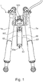
- system 1 comprises a pair of shock absorbers 1a in fluid connection to each other according to prior Patent PCT/EP2006/064794 to the same Applicant.
- the various types of elastic shock absorbers may include spring systems, in turn comprising helical and leaf springs generally made of metal material, rubber springs and the like, according to the known prior art.
- elastic shock absorbers may comprise gas springs.
- metals springs e.g. a helical spring, commonly used in traditional shock absorbers have a certain elastic constant which can be generally indicated by K.
- the elastic force opposed by the spring is linear with respect to the deformation: by way of example, with an elastic constant K being equal to 10, for each 10 kg of force axially applied to a helical spring, the length thereof varies by 1 mm. If a further axial force of 10 kg is applied to a spring already preloaded with 10 kg, the spring deforms again by 1 mm, until it reaches its maximum deformation, while sandwiching.
- Gas springs instead are progressive.
- the piston or membrane compressing the pressurized gas moves by a quota X.
- the piston or membrane moves by a quota Y, which is less than X because the bulk modulus of compressibility of a gas is not constant but depends on density. The denser the gas, the greater the variation in pressure required to obtain a further decrease of the volume.
- the improved spring system allows the suspension to be more effective throughout its work, and to be adequately adjusted in terms of pressures of the different chambers of the accumulators as a function of the type of use.
- the improved gas suspension 10, 10', 10", 20, 30, 40, 50 comprises at least one shock absorber 10a, 20a, 30a, 40a, 50a in fluid connection with at least a first accumulator 60, 80, 90, operatively connected to a second accumulator 70, 80a with variable volume, adapted to form an expansion chamber having a variable volume for said first accumulator 60, 80, 90.
- a suspension and tilting system in particular is shown for three- or four-wheel vehicles of which at least two are tilting wheels, and such a system comprises a pair of shock absorbers and each of said shock absorbers comprises at least one cylinder and at least one piston which is movable inside said cylinder and which divides the inner volume of the cylinder into two chambers, an upper chamber and a lower chamber.
- the upper chamber contains a working fluid in the liquid state, generally oil, and the lower chamber may also contain pressurized gas according to the teachings of PCT/EP2006/064794 mentioned above.
- Figure 1 depicts the suspension and tilting system known from PCT/EP2006/064794 .
- the present invention is not to be limited to the application to such a wheel suspension and tilting system according to the teaching of Application PCT/EP2006/064794 , and therefore any suspension and tilting system comprising a pair of shock absorbers connected to each other in fluid connection may be equally provided.
- At least one of the chambers of a first of said shock absorbers 10a, 20a advantageously is in fluid connection by means of a connecting duct 100 with the corresponding chamber of a second of said shock absorbers 10a, 20a, and advantageously said connecting duct 100 is in fluid connection with a first accumulator 60 serving the function of damper.
- Said first accumulator 60 in turn preferably comprises a containment cylinder 60' inside of which there is provided a first partition wall 60" slidably associated inside said containment cylinder 60' so that the working fluid, preferably oil as said, which flows through said duct 100 during the operation of the system, passing from the first to the second shock absorber and vice versa, may also expand inside said containment cylinder 60', in particular in an upper chamber 61 defined by said partition wall 60" inside cylinder 60', thus overcoming the resistance to the sliding of the partition wall 60" generated by the presence of pressurized gas in the lower chamber 62 of said cylinder 60'.
- the working fluid preferably oil as said
- the suspension further comprises a second accumulator 70 in fluid communication with said first accumulator.
- Said second accumulator 70 is characterized in that it has a variable volume.
- the second accumulator 70 having a variable volume comprises a preferably substantially cylindrical containment element 71 defining therein an expansion chamber 72 having a variable volume.
- Separation means are conveniently provided inside said containment element 71 in order to vary the volume of the expansion chamber 72, said separation means 73 being adapted to divide said expansion chamber 72 into two parts; a first part 72' in fluid communication with said first accumulator 60 and a second part 72" containing contrast means suitable for counteracting the displacement of said separation means 73, thus counteracting the volume increase of said first part 72' of said expansion chamber 72.
- said separation means 73 preferably consist of a balloon 73a.
- Said second part 72" of said expansion chamber 72 is therefore completely contained in said balloon 73a and said contrast means consist of gas pressurized at a pressure B, with which balloon 73a is filled through a suitable filling valve 73b.
- said containment element 71 is conveniently provided with a closure plug 75 on which said filling valve 73b is provided to allow the filling of said balloon 73a with gas.
- suspension 10 provides for the accumulator 70 having a variable volume be added to the suspension and tilting system of known type without particular modifications to the system itself. More specifically, the second accumulator 70 having a variable volume is directly connected to the first accumulator 60 by simply replacing the lower closure plug 63 of said first accumulator 60.
- the charge of the pressure of the gas in the first accumulator 60 is carried out by means of a first filling valve 200 once said second accumulator 70 is connected, while the charge of the pressure of the gas in the second accumulator 70 having a variable volume is carried out by means of a second filling valve 300 arranged on said second accumulator 70.
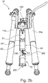
- FIG. 2b another embodiment of suspension 10' differs from the one shown in Figure 2a in that said second accumulator 70 having a variable volume is directly connected to the closure plug 63 by means of a nipple 63b accommodated in place of valve 63a shown in Figure 1 in the prepared seat.
- the adjustment of the pressure of the lower chamber 62 of said accumulator may be possible only when the second accumulator 70 has been connected, and by means of said first filling valve 200.
- the charge of said second accumulator 70 may occur by means of a dedicated filling valve indicated by numeral 300, which is entirely similar to valve 73b shown in Figure 5 provided on plug 75 of said second accumulator 70.
- the second accumulator 70 having a variable volume can be connected without modifications to the suspension system, and in particular to the first accumulator 60. Indeed, by removing valve 63a and replacing said valve with a nipple 63b, the second accumulator 70 having a variable volume may be connected directly to the closure plug 63.
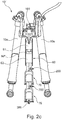
- suspension 10" differs from the one shown in Figure 2a in that a third accumulator 76 having a variable volume is connected to the second accumulator 70 having a variable volume.
- the gradual engagement of the suspension may be further improved with this type of configuration, and accordingly the driving comfort, as better explained below.
- the charge of the first accumulator 60 may occur by means of a first filling valve 200, with the second accumulator 70 being connected.
- the charge of the second accumulator 70 may occur by means of a second filling valve 200' arranged on the stretch of connection connecting said third accumulator
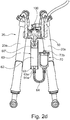
- connection of the second accumulator 70 having a variable volume to the first accumulator 60 preferably occurs by means of a flexible tube 64 adapted to directly connect valve 63a arranged on said plug 63 to the second accumulator 70 having a variable volume.
- This embodiment is particularly preferred if a suspension and tilting system of an existing vehicle is to be modified according to the present invention without modifying anything.
- said second accumulator having a variable volume is shown integrated in the first accumulator 80.
- said first accumulator 80 comprises a containment cylinder 80', closed at the bottom by a bottom wall, internally provided with a first partition wall 80" slidably associated within said containment cylinder 80', which is thus divided into an upper chamber 81 and a lower chamber 82.
- said lower chamber 82 of said first accumulator 80 in turn comprises separation means 83 adapted to divide said lower chamber 82 of said first accumulator 80 into two parts.
- Said separation means 83 preferably comprise here a second partition wall 83' adapted to divide said lower chamber 82 into two parts; a first part 82' between said first partition wall 80" and said second partition wall 83', a second part 82" between said second partition wall 83' and the bottom wall of said containment cylinder 80'.
- said upper chamber 81 of said first accumulator 80 is in fluid connection with the hydraulic circuit connecting said shock absorbers 10a to one another, and therefore it is configured to receive the working fluid (typically oil) enclosed in the upper chambers of said shock absorbers 10a.
- the working fluid is capable of flowing inside the upper chamber 81 of said first accumulator 80 and counteracting said first partition wall 80".
- Gas is present at a second pressure value, generally indicated by B, in the second part 82" of said lower chamber 82 between said second partition wall 83' and the bottom wall of said containment cylinder 80'.
- said first accumulator 80 will be provided with a first gas filling valve 84 for filling the gas contained in said first part 82' of said lower chamber 82, and with a second gas filling valve 85 for filling the gas contained in said second part 82" of said lower chamber 82.
- the suspension and tilting system 40 comprises a first accumulator 80 which, similarly to that shown above, in turn comprises a first 80" and a second 83' partition wall, however said second part 82" of said lower chamber 82, which is arranged below said second partition wall 83', advantageously comprises elastic means, for example a helical spring 86 interposed between the bottom wall of said containment cylinder 80' and said second partition wall 83'.
- the improved suspension 50 comprises a shock absorber 50a comprising at least one oil chamber 51 in fluid connection with a first accumulator 90 comprising a containment cylinder 90' internally housing a first partition wall 90", slidably associated within said containment cylinder 90' which is thus divided into an upper chamber 91 and a lower chamber 92.
- a pressurized gas is conveniently contained in said lower chamber 92.
- Suspension 50 further comprises a second accumulator 70 having a variable volume, having the same features described above with reference to the embodiment shown in Figure 5 . Said second accumulator 70 is in fluid connection with said first accumulator 90.
- the suspension according to this embodiment can also be used on motorcycles provided with rear mono-shock absorber, as depicted in Figure 9 .
- the line indicated by letter a in the graph depicts the behavior of an HTS suspension in standard configuration, i.e. according to the known configuration of Figure 1 .
- the suspension has an excessively progressive reaction, i.e. in the second part of the compression the load increases excessively, which is very different with respect to how much it increases in a spring suspension with a constant elastic constant K, the behavior of which is depicted by the line indicated by letter e in the graph.
- the line indicated by letter b depicts the behavior of a suspension according to, for example, the embodiment shown in Figures 2a , 2b , 2d , 3 , 6 , 7 and 8 in which a second accumulator having a variable volume is associated with the first accumulator.
- the second accumulator contributes to modifying the dynamic behavior of the suspension by implementing the progressive behaviour which is typical of a gas suspension and therefore making the response of the suspension more linear.
- the line indicated by letter c in the graph depicts the response of the same configuration in which different pressures are implemented in the accumulators.
- Line d depicts the behavior of a suspension according to, for example, the embodiment shown in Figure 2c , in which a third accumulator having a variable volume is associated with the first two accumulators.
- the intermediate position where the curves of the suspension are positioned according to the present invention, corresponds to the best comfort level perceived when using the vehicle.
- the improved suspension according to the present invention when associated with a tilting system of the wheels of a vehicle with tilting wheels, as when the invention is applied to the HTS suspension and tilting system shown in Figure 1 or to similar systems, the invention allows to obtain a different transfer of the load during braking, which positively affects the entry of the vehicle into a bend.
Landscapes
- Engineering & Computer Science (AREA)
- Mechanical Engineering (AREA)
- Vehicle Body Suspensions (AREA)
- Axle Suspensions And Sidecars For Cycles (AREA)
- Fluid-Damping Devices (AREA)
- Arrangement Or Mounting Of Propulsion Units For Vehicles (AREA)
Description
- The present invention relates to an improved suspension.
- A suspension of this kind is known for example from
WO 2009/087595 . - In particular, the suspension according to the present invention was conceived for traditional two-wheel motorcycles and/or for motorcycles or vehicles having three or more wheels with at least two tilting wheels, wherein however other uses thereof in other vehicles are equally possible.
- Vehicles with tilting wheels are motor vehicles, motorcycles, scooters or the like which are generally provided with a pair of tilting front wheels and with one rear wheel; vehicles with two rear wheels are also considered. In general, the expression vehicles with tilting wheels has to be understood as meaning vehicles which have at least three wheels and which are capable of tilting sideways due to the presence of a so-called tilting system of the wheels coupled on the same axis, generally the front wheels.
- According to the known background art, vehicle suspensions comprise at least one shock absorber. In vehicles with two or more wheels, suspension systems connect the wheels to the frame. The suspensions comprise elastic shock absorbers which carry out the function of dampening the stresses transmitted from the road to the frame.
- An example of such suspension and tilting systems is provided in
Figure 1 , wheresystem 1 comprises a pair of shock absorbers 1a in fluid connection to each other according to prior PatentPCT/EP2006/064794 - The various types of elastic shock absorbers may include spring systems, in turn comprising helical and leaf springs generally made of metal material, rubber springs and the like, according to the known prior art.
- Alternatively, elastic shock absorbers may comprise gas springs.
- In contrast to gas springs, metals springs, e.g. a helical spring, commonly used in traditional shock absorbers have a certain elastic constant which can be generally indicated by K.
- Due to said constant, the elastic force opposed by the spring is linear with respect to the deformation: by way of example, with an elastic constant K being equal to 10, for each 10 kg of force axially applied to a helical spring, the length thereof varies by 1 mm. If a further axial force of 10 kg is applied to a spring already preloaded with 10 kg, the spring deforms again by 1 mm, until it reaches its maximum deformation, while sandwiching.
- Gas springs instead are progressive. By way of example, if 100 kg of axial force are applied to a gas spring, the piston or membrane compressing the pressurized gas moves by a quota X.
- By applying a further 100 kg, the piston or membrane moves by a quota Y, which is less than X because the bulk modulus of compressibility of a gas is not constant but depends on density. The denser the gas, the greater the variation in pressure required to obtain a further decrease of the volume.
- The excessive gradual engagement of gas springs creates a problem of excessive rigidity of the suspension, generally from mid-stroke onward, thus adversely affecting the driving comfort.
- Document
US3854710 discloses a suspension according to the preamble ofclaim 1. - It is the main task of the present invention to provide an improved suspension which allows to overcome the drawbacks left unsolved by solutions of known type. Within this task, it is the object of the present invention to provide a suspension capable of providing an adequately progressive performance without having simultaneous problems of excessive gradual engagement, which affect the currently known suspensions comprising gas shock absorbers.
- It is also an object of the present invention to improve the comfort offered by the gas suspension, both when driving alone and when driving with the passenger, and also when driving with the passenger and luggage.
- Indeed, the improved spring system allows the suspension to be more effective throughout its work, and to be adequately adjusted in terms of pressures of the different chambers of the accumulators as a function of the type of use.
- Thereby, it is possible to customize the performance of the suspension as a function of the type of use (sports, touring, etc.) and of the load weighing thereon (driving alone, with passenger, etc.). This task and these and other objects are achieved by an improved suspension according to appended
claim 1. - Further features are mentioned in the dependent claims.
- Further features and advantages of the present invention will be more apparent from the detailed description of a preferred embodiment, depicted by way of a non-limiting example in the accompanying drawings, in which:
-
Figure 1 depicts a suspension andtilting system 1 referred to as HTS (Hydraulic Tilting System), for vehicles having tilting wheels, known from the prior art and belonging to the subject matter of International Patent ApplicationPCT/EP2006/064794 -
Figure 2a depicts the suspension and tilting system ofFigure 1 , comprising an added accumulator with variable volume associated with the HTS suspension according to a first embodiment and to a first connection mode, not forming part of the present invention; -
Figure 2b depicts the suspension and tilting system ofFigure 1 , comprising an added accumulator with variable volume associated with the HTS suspension according to a first embodiment and to a second connection mode, not forming part of the present invention; -
Figure 2c depicts the suspension and tilting system ofFigure 1 , comprising a first added accumulator with variable volume associated with the HTS suspension according to a first embodiment and to a third connection mode, not forming part of the present invention; -
Figure 2d depicts the suspension and tilting system ofFigure 1 , comprising a second accumulator with variable volume associated with the HTS suspension according to a first embodiment and to a fourth connection mode, not forming part of the present invention; -
Figure 3 depicts the suspension and tilting system ofFigure 2d in a first stroking step of the suspension system; -
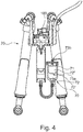
Figure 4 depicts the suspension and tilting system inFigure 2d in a second stroking step of the suspension system, at which the pressure value of the gas in the system is such as to cause the volume of the second accumulator with variable volume, to vary; -
Figure 5 depicts, in detail, the accumulator with variable volume according to the embodiment ofFigures 2a-2d ; -
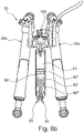
Figure 6 depicts the suspension and tilting system ofFigure 1 with which an accumulator with variable volume according to a first embodiment of the present invention is associated; -
Figure 6a depicts the suspension and tilting system ofFigure 6 in a first stroking step of the suspension system; -
Figure 6b depicts the suspension and tilting system ofFigure 6 in a second stroking step of the suspension system, at which the pressure value of the gas in the system is such as to cause the volume of the second accumulator with variable volume, to vary; -
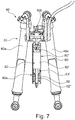
Figure 7 depicts the suspension and tilting system ofFigure 1 with which an accumulator with variable volume according to a second embodiment of the present invention is associated; -
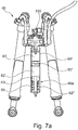
Figure 7a depicts the suspension and tilting system ofFigure 7 in a first stroking step of the suspension system; -
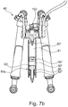
Figure 7b depicts the suspension and tilting system ofFigure 7 in a second stroking step of the suspension system, at which the pressure value of the gas in the system is such as to cause the volume of the accumulator with variable volume, to vary; -
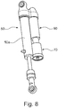
Figure 8 depicts a mono-shock absorber of the type suitable for forming the rear suspension of a motorcycle, with which an accumulator with variable volume not forming part of the present invention is associated; -
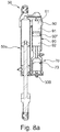
Figure 8a depicts a sectional view of the mono-shock absorber with accumulator ofFigure 8 ; -
Figure 9 depicts a motorcycle on which the mono-shock absorber with accumulator ofFigure 8 , is installed; -
Figure 10 depicts a graph showing the compression of the suspension as a function of the load according to the various configurations. - The improved
gas suspension first accumulator second accumulator first accumulator - In the embodiments of
Figures 2a to 7b , a suspension and tilting system in particular is shown for three- or four-wheel vehicles of which at least two are tilting wheels, and such a system comprises a pair of shock absorbers and each of said shock absorbers comprises at least one cylinder and at least one piston which is movable inside said cylinder and which divides the inner volume of the cylinder into two chambers, an upper chamber and a lower chamber. The upper chamber contains a working fluid in the liquid state, generally oil, and the lower chamber may also contain pressurized gas according to the teachings ofPCT/EP2006/064794 -
Figure 1 depicts the suspension and tilting system known fromPCT/EP2006/064794 - However, the present invention is not to be limited to the application to such a wheel suspension and tilting system according to the teaching of Application
PCT/EP2006/064794 - Returning to the example depicted in the accompanying
Figures 2a to 5 , at least one of the chambers of a first of saidshock absorbers duct 100 with the corresponding chamber of a second of saidshock absorbers duct 100 is in fluid connection with afirst accumulator 60 serving the function of damper. - Said
first accumulator 60 in turn preferably comprises a containment cylinder 60' inside of which there is provided afirst partition wall 60" slidably associated inside said containment cylinder 60' so that the working fluid, preferably oil as said, which flows throughsaid duct 100 during the operation of the system, passing from the first to the second shock absorber and vice versa, may also expand inside said containment cylinder 60', in particular in anupper chamber 61 defined by saidpartition wall 60" inside cylinder 60', thus overcoming the resistance to the sliding of thepartition wall 60" generated by the presence of pressurized gas in thelower chamber 62 of said cylinder 60'. - The suspension further comprises a
second accumulator 70 in fluid communication with said first accumulator. - Said
second accumulator 70 is characterized in that it has a variable volume. - With particular reference to the detail in
Figure 5 , thesecond accumulator 70 having a variable volume comprises a preferably substantiallycylindrical containment element 71 defining therein anexpansion chamber 72 having a variable volume. - Separation means are conveniently provided inside said
containment element 71 in order to vary the volume of theexpansion chamber 72, said separation means 73 being adapted to divide saidexpansion chamber 72 into two parts; afirst part 72' in fluid communication with saidfirst accumulator 60 and asecond part 72" containing contrast means suitable for counteracting the displacement of said separation means 73, thus counteracting the volume increase of saidfirst part 72' of saidexpansion chamber 72. - According to the embodiment shown in
Figures 2a to 4 , said separation means 73 preferably consist of aballoon 73a. - Said
second part 72" of saidexpansion chamber 72 is therefore completely contained in saidballoon 73a and said contrast means consist of gas pressurized at a pressure B, with whichballoon 73a is filled through asuitable filling valve 73b. Advantageously, saidcontainment element 71 is conveniently provided with aclosure plug 75 on which said fillingvalve 73b is provided to allow the filling of saidballoon 73a with gas. - With reference to
Figure 2a ,suspension 10 provides for theaccumulator 70 having a variable volume be added to the suspension and tilting system of known type without particular modifications to the system itself. More specifically, thesecond accumulator 70 having a variable volume is directly connected to thefirst accumulator 60 by simply replacing thelower closure plug 63 of saidfirst accumulator 60. Here, the charge of the pressure of the gas in thefirst accumulator 60 is carried out by means of afirst filling valve 200 once saidsecond accumulator 70 is connected, while the charge of the pressure of the gas in thesecond accumulator 70 having a variable volume is carried out by means of asecond filling valve 300 arranged on saidsecond accumulator 70. - With reference to
Figure 2b , another embodiment of suspension 10' differs from the one shown inFigure 2a in that saidsecond accumulator 70 having a variable volume is directly connected to theclosure plug 63 by means of anipple 63b accommodated in place ofvalve 63a shown inFigure 1 in the prepared seat. According to this configuration, the adjustment of the pressure of thelower chamber 62 of said accumulator may be possible only when thesecond accumulator 70 has been connected, and by means of said first fillingvalve 200. The charge of saidsecond accumulator 70 may occur by means of a dedicated filling valve indicated bynumeral 300, which is entirely similar tovalve 73b shown inFigure 5 provided onplug 75 of saidsecond accumulator 70. - Among the advantages of the configuration shown in
Figure 2b , it is worth noting that thesecond accumulator 70 having a variable volume can be connected without modifications to the suspension system, and in particular to thefirst accumulator 60. Indeed, by removingvalve 63a and replacing said valve with anipple 63b, thesecond accumulator 70 having a variable volume may be connected directly to theclosure plug 63. - With this configuration, as well as with the configuration in
Figure 2a , the pressure in the first accumulator is charged upon connection of thesecond accumulator 70 having a variable volume. - With reference to
Figure 2c , another embodiment ofsuspension 10" differs from the one shown inFigure 2a in that athird accumulator 76 having a variable volume is connected to thesecond accumulator 70 having a variable volume. The gradual engagement of the suspension may be further improved with this type of configuration, and accordingly the driving comfort, as better explained below. - Also in this case, the charge of the
first accumulator 60 may occur by means of afirst filling valve 200, with thesecond accumulator 70 being connected. Similarly, the charge of thesecond accumulator 70 may occur by means of a second filling valve 200' arranged on the stretch of connection connecting said third accumulator - 76 with said
second accumulator 70. Finally, the charge of saidthird accumulator 76 occurs by means of adedicated charge 300 similarly to that described with reference to the embodiments inFigures 2a and2b . - With reference to
Figure 2d , in this embodiment the connection of thesecond accumulator 70 having a variable volume to thefirst accumulator 60 preferably occurs by means of aflexible tube 64 adapted to directly connectvalve 63a arranged on saidplug 63 to thesecond accumulator 70 having a variable volume. - This embodiment is particularly preferred if a suspension and tilting system of an existing vehicle is to be modified according to the present invention without modifying anything.
- Indeed, the integration of the added accumulator on an existing HTS system or HTS system already in use on the market materializes by screwing the threaded
connector 64a of theflexible tube 64 tovalve 63a. Therefore, the solution lends itself to adapting existing suspension systems. - In an embodiment of
suspension 30 according to the present invention shown by way of example inFigures 6 ,6a and6b , said second accumulator having a variable volume is shown integrated in thefirst accumulator 80. - More specifically, said
first accumulator 80 comprises a containment cylinder 80', closed at the bottom by a bottom wall, internally provided with afirst partition wall 80" slidably associated within said containment cylinder 80', which is thus divided into anupper chamber 81 and alower chamber 82. - Advantageously, said
lower chamber 82 of saidfirst accumulator 80 in turn comprises separation means 83 adapted to divide saidlower chamber 82 of saidfirst accumulator 80 into two parts. Said separation means 83 preferably comprise here a second partition wall 83' adapted to divide saidlower chamber 82 into two parts; a first part 82' between saidfirst partition wall 80" and said second partition wall 83', asecond part 82" between said second partition wall 83' and the bottom wall of said containment cylinder 80'. - Gas is present at a first pressure value, generally indicated by A, in the first part 82' of said
lower chamber 82 between saidfirst partition wall 80" and said second partition wall 83'. Therefore, in the configuration hereto described, saidaccumulator 80a having a variable volume is obtained inside saidfirst accumulator 80. - Operatively, said
upper chamber 81 of saidfirst accumulator 80 is in fluid connection with the hydraulic circuit connecting saidshock absorbers 10a to one another, and therefore it is configured to receive the working fluid (typically oil) enclosed in the upper chambers of saidshock absorbers 10a. - Therefore, the working fluid is capable of flowing inside the
upper chamber 81 of saidfirst accumulator 80 and counteracting saidfirst partition wall 80". - Gas is present at a second pressure value, generally indicated by B, in the
second part 82" of saidlower chamber 82 between said second partition wall 83' and the bottom wall of said containment cylinder 80'. - When the thrust exerted on said second partition wall 83' by pressure A of the gas contained in said first part 82' of said
lower chamber 82 exceeds the force of reaction exerted by pressure B of the gas contained in saidsecond part 82"of saidlower chamber 82, the volume of thelower chamber 82" will be reduced and thefirst accumulator 80 will behave like an accumulator having a variable volume; vice versa, as long as the thrust exerted on said second partition wall 83' by pressure A of the gas contained in said first part 82' of saidlower chamber 82 is lower than the force of reaction exerted by pressure B of the gas contained in saidsecond part 82"of saidlower chamber 82, thefirst accumulator 80 will behave like a traditional accumulator. - Due to the possibility of increasing the volume inside
accumulator 80, same becomes an accumulator having a variable volume and the suspension system according to the present invention therefore allows the drawbacks which are typical of gas suspensions to be obviated, in particular by obviating an excessive rigidity of the suspension from the second part of the travel up to the stroke end. Advantageously, saidfirst accumulator 80 will be provided with a firstgas filling valve 84 for filling the gas contained in said first part 82' of saidlower chamber 82, and with a secondgas filling valve 85 for filling the gas contained in saidsecond part 82" of saidlower chamber 82. - In an alternative embodiment of the present invention shown in
Figures 7 and7a , the suspension and tiltingsystem 40 comprises afirst accumulator 80 which, similarly to that shown above, in turn comprises a first 80" and a second 83' partition wall, however saidsecond part 82" of saidlower chamber 82, which is arranged below said second partition wall 83', advantageously comprises elastic means, for example ahelical spring 86 interposed between the bottom wall of said containment cylinder 80' and said second partition wall 83'. - According to the embodiment shown by way of example in
Figures 8 and8a , theimproved suspension 50 comprises ashock absorber 50a comprising at least oneoil chamber 51 in fluid connection with afirst accumulator 90 comprising a containment cylinder 90' internally housing afirst partition wall 90", slidably associated within said containment cylinder 90' which is thus divided into anupper chamber 91 and alower chamber 92. Advantageously, a pressurized gas is conveniently contained in saidlower chamber 92.Suspension 50 further comprises asecond accumulator 70 having a variable volume, having the same features described above with reference to the embodiment shown inFigure 5 . Saidsecond accumulator 70 is in fluid connection with saidfirst accumulator 90. - The suspension according to this embodiment can also be used on motorcycles provided with rear mono-shock absorber, as depicted in
Figure 9 . - It has thus been shown how the improved suspension according to the present invention achieves the predetermined tasks and objects.
- It is worth noting the following, with particular reference to the graph in
Figure 10 showing the compression trend of the suspension (expressed in mm) as the load applied (expressed in kg) varies. - The line indicated by letter a in the graph depicts the behavior of an HTS suspension in standard configuration, i.e. according to the known configuration of
Figure 1 . - As is noted from the trend in the graph, the suspension has an excessively progressive reaction, i.e. in the second part of the compression the load increases excessively, which is very different with respect to how much it increases in a spring suspension with a constant elastic constant K, the behavior of which is depicted by the line indicated by letter e in the graph.
- The line indicated by letter b depicts the behavior of a suspension according to, for example, the embodiment shown in
Figures 2a ,2b ,2d ,3 ,6 ,7 and8 in which a second accumulator having a variable volume is associated with the first accumulator. - It is worth noting how the second accumulator contributes to modifying the dynamic behavior of the suspension by implementing the progressive behaviour which is typical of a gas suspension and therefore making the response of the suspension more linear.
- The line indicated by letter c in the graph depicts the response of the same configuration in which different pressures are implemented in the accumulators.
- Line d depicts the behavior of a suspension according to, for example, the embodiment shown in
Figure 2c , in which a third accumulator having a variable volume is associated with the first two accumulators. - It is worth noting how the progressive behavior of the suspension is further reduced.
- It is apparent from the graph that, with respect to curve a depicting a suspension provided with a single accumulator, and with respect to curve e depicting the behavior of a helical spring suspension having an elastic constant K, the curves b, c and d are positioned in intermediate position, therefore not excessively progressive like the system provided with one accumulator alone, and not excessively yielding like what occurs instead in the case of a spring with K constant.
- This results also in driving conditions, for example of two people, with driver and passenger, in which the behavior of the suspension does not become excessively rigid as would occur with a single accumulator suspension when disconnections of the ground are encountered during driving: considering that the first part of compression of the suspension is caused by the weight of the passenger which is added to the one of the driver, the second remaining part of compression ensuring the driving comfort is less rigid but in any case is not excessively soft like in the case of elastic spring with constant k, which normally by default has the characteristic of quickly going to stroke end.
- The intermediate position, where the curves of the suspension are positioned according to the present invention, corresponds to the best comfort level perceived when using the vehicle.
- Moreover, in addition to the above improvements to the comfort level, when the improved suspension according to the present invention is associated with a tilting system of the wheels of a vehicle with tilting wheels, as when the invention is applied to the HTS suspension and tilting system shown in
Figure 1 or to similar systems, the invention allows to obtain a different transfer of the load during braking, which positively affects the entry of the vehicle into a bend. - Thereby, it was experimentally detected that by changing the transfer value of the load during braking, in particular by increasing the transfer of the load due to a less rigid response of the suspension during the initial load step, the pressures of the oil inside the chambers accordingly vary significantly, in particular they increase, and accordingly the frictions exerted by the gaskets on the seal elements affect the sliding of the parts of the HTS. Thus, a feeling of increased stability is obtained in the step of setting up the bend: the hydraulic gaskets are energized by the pressure itself of the oil which, having an increased value, increasingly create friction on the movement of the pistons on the cylinders of the HTS, and therefore the tilting movement of the vehicle, a condition which makes the driving sensation pleasant in the first step of travelling the bend.
- Several changes, modifications, variations and other uses and applications of the invention at hand will become apparent to those skilled in the art after considering the description and the accompanying drawings which show the preferred embodiments thereof.
Claims (6)
- Suspension comprising a pair of shock absorbers (30a, 40a), a first gas accumulator (80) and a connecting duct (100) by means of which said pair of shock absorbers (30a, 40a) are in fluid connection with each other, said connecting duct (100) being in turn in fluid connection with said first gas accumulator (80), characterized in that said suspension further comprises a second accumulator (80a) having a variable volume, amd in that said second accumulator (80a) is formed inside said first gas accumulator (80).
- Suspension according to claim 1, wherein said first gas accumulator (80) comprises a cylindrical containment cylinder (80'), closed at its bottom by a bottom wall, and a first partition wall (80"), slidably associated within said containment cylinder (80') and dividing said containment cylinder (80') into an upper chamber (81) and a lower chamber (82), and wherein said second accumulator (80a) comprises a second partition wall (83') dividing said lower chamber (82) into a first part (82') comprised between said first partition wall (80") and said second partition wall (83') and a second part (82") comprised between said second partition wall (83') and said bottom wall.
- Suspension according to claim 2, wherein gas at a first pressure value (A) is present in said first part (82') of said lower chamber (82), and gas at a second pressure value (B) is present in said second part (82") of said lower chamber (82).
- Suspension according to claim 2, wherein said second part (82") of said lower chamber (82) contains elastic means (86) interposed between said bottom wall and said second partition wall (83').
- Suspension according to claim 4, wherein said elastic means comprise a helical spring (86).
- Vehicle with two or more wheels, comprising a suspension according to any one of the preceding claims.
Applications Claiming Priority (2)
| Application Number | Priority Date | Filing Date | Title |
|---|---|---|---|
| ITUA2016A001684A ITUA20161684A1 (en) | 2016-03-15 | 2016-03-15 | IMPROVED SUSPENSION |
| PCT/EP2017/056053 WO2017157976A1 (en) | 2016-03-15 | 2017-03-15 | Improved suspension |
Publications (2)
| Publication Number | Publication Date |
|---|---|
| EP3429873A1 EP3429873A1 (en) | 2019-01-23 |
| EP3429873B1 true EP3429873B1 (en) | 2020-08-12 |
Family
ID=56203722
Family Applications (1)
| Application Number | Title | Priority Date | Filing Date |
|---|---|---|---|
| EP17716797.0A Active EP3429873B1 (en) | 2016-03-15 | 2017-03-15 | Improved suspension |
Country Status (14)
| Country | Link |
|---|---|
| US (1) | US20190077210A1 (en) |
| EP (1) | EP3429873B1 (en) |
| JP (1) | JP2019513208A (en) |
| CN (1) | CN109476200B (en) |
| AR (1) | AR108349A1 (en) |
| BR (1) | BR112018068764A2 (en) |
| CA (1) | CA3017818A1 (en) |
| ES (1) | ES2831081T3 (en) |
| IT (1) | ITUA20161684A1 (en) |
| MA (2) | MA45487A (en) |
| PH (1) | PH12018501992A1 (en) |
| RU (1) | RU2018136056A (en) |
| TW (1) | TWI838329B (en) |
| WO (1) | WO2017157976A1 (en) |
Families Citing this family (8)
| Publication number | Priority date | Publication date | Assignee | Title |
|---|---|---|---|---|
| FR3074099B1 (en) * | 2017-11-24 | 2019-10-18 | Psa Automobiles Sa | HYDROPNEUMATIC SUSPENSION DEVICE FOR A RECLINING MOTOR VEHICLE WITH BLOCKING OF THE ROLLER AT OFF |
| IT201800002190A1 (en) * | 2018-01-30 | 2019-07-30 | Quadro Vehicles Sa | SUSPENSION MODULE FOR WHEELED VEHICLES / SUSPENSION MODULE FOR WHEELED VEHICLES |
| ES3047393T3 (en) * | 2019-01-29 | 2025-12-03 | Qooder S A | Hydropneumatic system for controlling the tilting of two wheels of a vehicle and a vehicle equipped with said system |
| JP2020168898A (en) * | 2019-04-01 | 2020-10-15 | ヤマハ発動機株式会社 | Suspension system and vehicle |
| JP7285118B2 (en) | 2019-04-01 | 2023-06-01 | ヤマハ発動機株式会社 | Suspension system and vehicle |
| US11338877B2 (en) * | 2019-06-25 | 2022-05-24 | Julian Zheng | Two-wheel automatic balance reset mechanism and system |
| IT201900020182A1 (en) * | 2019-10-31 | 2021-05-01 | Qooder S A | Three or more wheeled vehicle with hydraulic oscillation system and with oscillation blocking system |
| KR20250074021A (en) * | 2023-11-20 | 2025-05-27 | 에이치엘만도 주식회사 | Accumulator and suspension system of vehicle including the same |
Family Cites Families (41)
| Publication number | Priority date | Publication date | Assignee | Title |
|---|---|---|---|---|
| GB870826A (en) * | 1958-12-11 | 1961-06-21 | Armstrong Patents Co Ltd | Improvements in or relating to hydro-pneumatic suspension systems |
| GB1004481A (en) * | 1962-01-25 | 1965-09-15 | Moulton Development Ltd | Improvements in vehicle wheel suspension systems |
| GB1380900A (en) * | 1970-12-29 | 1975-01-15 | Girling Ltd | Suspension systems |
| US4872702A (en) * | 1988-08-23 | 1989-10-10 | Kress Corporation | Suspension system for vehicles |
| JPH02109713A (en) * | 1988-10-20 | 1990-04-23 | Tokico Ltd | suspension device |
| US5098119A (en) * | 1991-03-22 | 1992-03-24 | Trw Inc. | Semi-active suspension system with energy saving |
| US5486018A (en) * | 1994-08-05 | 1996-01-23 | Yamaha Hatsudoki Kabushiki Kaisha | Suspension system for four-wheeled vehicles |
| JPH08296691A (en) * | 1995-04-26 | 1996-11-12 | Kayaba Ind Co Ltd | Frequency sensitive damping force adjustment device |
| CN2365455Y (en) * | 1998-09-03 | 2000-02-23 | 南京建筑工程学院 | Spring vibration-damper using both gas and oil for vehicle |
| AU2001293489A1 (en) * | 2000-09-28 | 2002-04-08 | Graeme K Robertson | Suspension system |
| ATE421640T1 (en) * | 2002-05-29 | 2009-02-15 | Progressive Suspension Inc | HYDRAULIC DAMPERS WITH PRESSURE CONTROL VALVE AND SECONDARY PISTON |
| DE50305547D1 (en) * | 2002-08-09 | 2006-12-14 | Jun Kerler | Pneumatic suspension and height adjustment for vehicles |
| FR2849625B1 (en) * | 2003-01-08 | 2006-05-26 | Peugeot Citroen Automobiles Sa | MOTOR VEHICLE WITH AUTOADAPTATIVE OLEOPNEUMATIC SUSPENSION |
| US7124865B2 (en) * | 2004-02-13 | 2006-10-24 | Progressive Suspension, Inc. | Pressure regulating dampers |
| JP2006076469A (en) * | 2004-09-10 | 2006-03-23 | Toyota Motor Corp | Suspension device |
| EP1853442B1 (en) * | 2005-03-01 | 2018-11-14 | Kinetic Pty Ltd. | Hydraulic system for a vehicle suspension |
| ES2344997T3 (en) * | 2006-07-28 | 2010-09-13 | Marabese Design S.R.L. | SYSTEM FOR CONTROLLING COMPENSATION ON MOTORCYCLES WITH THREE OR FOUR WHEELS. |
| CN101688580A (en) * | 2007-03-20 | 2010-03-31 | 维克多·汉纳蒂耶维奇·帕勒沃泽夫 | Method for adjusting valve volume in a shock absorber and shock absorber with adjustable valve volume |
| ITMI20080018A1 (en) * | 2008-01-08 | 2009-07-09 | Marabese Design S R L | WHEEL PENDULUM SYSTEM FOR THREE OR MORE WHEEL VEHICLES |
| WO2009111826A1 (en) * | 2008-03-10 | 2009-09-17 | Kinetic Pty Ltd | Vehicle suspension arrangements & control |
| CN101392810B (en) * | 2008-11-05 | 2010-08-25 | 北京理工大学 | External adjustable damping valve for oil and gas suspension |
| CN101412355A (en) * | 2008-11-27 | 2009-04-22 | 北京理工大学 | External electromagnetic valve type three-stage damping adjustable hydro-pneumatic suspension for electric control |
| US8123240B2 (en) * | 2009-07-10 | 2012-02-28 | Bombardier Recreational Products Inc. | Control system for leaning vehicle |
| EP2312180B1 (en) * | 2009-10-13 | 2019-09-18 | Fox Factory, Inc. | Apparatus for controlling a fluid damper |
| DE102010055830A1 (en) * | 2010-12-23 | 2012-06-28 | Dt Swiss Ag | Suspension control for a bicycle |
| FR2977833B1 (en) * | 2011-07-11 | 2014-02-28 | Bianchi Mauro Sa | SUSPENSION METHOD AND SHOCK ABSORBER ASSEMBLY FOR A MOTOR VEHICLE |
| JP2013071523A (en) * | 2011-09-27 | 2013-04-22 | Aisin Seiki Co Ltd | Suspension system |
| US8960697B2 (en) * | 2011-11-09 | 2015-02-24 | Aisin Seiki Kabushiki Kaisha | Suspension device for vehicle |
| US8682528B2 (en) * | 2011-12-20 | 2014-03-25 | Caterpillar Inc. | Seat suspension system having fail-safe functionality |
| US8543291B2 (en) * | 2012-02-10 | 2013-09-24 | Steven P Young | Hydraulic wheel suspension system for a 3-wheeled motorcycle |
| US8801017B2 (en) * | 2012-03-26 | 2014-08-12 | Oshkosh Corporation | Position dependent damper for a vehicle suspension system |
| JP2013210079A (en) * | 2012-03-30 | 2013-10-10 | Hitachi Automotive Systems Ltd | Fastening member and compressor apparatus |
| KR101673641B1 (en) * | 2012-05-22 | 2016-11-07 | 현대자동차주식회사 | Vehicle shock absorber |
| CN102700412A (en) * | 2012-06-12 | 2012-10-03 | 中联重科股份有限公司 | Construction Machinery and Additional Axle Devices |
| WO2014065385A1 (en) * | 2012-10-25 | 2014-05-01 | ヤマハ発動機株式会社 | Vehicle |
| CN103009955B (en) * | 2012-12-24 | 2015-02-18 | 中联重科股份有限公司 | Air pressure adjustable oil-pneumatic suspension system and its air pressure adjustment method and engineering vehicle |
| US9139064B2 (en) * | 2013-08-22 | 2015-09-22 | GM Global Technology Operations LLC | Damper assembly for vehicle suspension system with fluid damper and multi-chamber gas spring and method of controlling pre-load, spring rate and ride height |
| EP2860069A1 (en) * | 2013-10-10 | 2015-04-15 | Iveco Magirus Ag | Method for using a spare wheel as air tank |
| DE102014209328A1 (en) * | 2014-05-16 | 2015-11-19 | Ford Global Technologies, Llc | Wheel suspension for a tilting suspension and taillight, as well as procedures for its operation and suitably equipped vehicle |
| ES2699269T3 (en) * | 2014-06-20 | 2019-02-08 | Quadro Vehicles S A | Improved stability control system for vehicles with more than two wheels |
| MX2017000131A (en) * | 2014-07-04 | 2017-05-30 | Quadro Vehicles Sa | Electronic braking device of the tilting system of a vehicle with three or more tilting wheels. |
-
2016
- 2016-03-15 IT ITUA2016A001684A patent/ITUA20161684A1/en unknown
-
2017
- 2017-03-10 AR ARP170100612A patent/AR108349A1/en unknown
- 2017-03-15 EP EP17716797.0A patent/EP3429873B1/en active Active
- 2017-03-15 CN CN201780026931.0A patent/CN109476200B/en active Active
- 2017-03-15 JP JP2018548809A patent/JP2019513208A/en active Pending
- 2017-03-15 US US16/085,401 patent/US20190077210A1/en not_active Abandoned
- 2017-03-15 CA CA3017818A patent/CA3017818A1/en not_active Abandoned
- 2017-03-15 TW TW106108525A patent/TWI838329B/en active
- 2017-03-15 RU RU2018136056A patent/RU2018136056A/en not_active Application Discontinuation
- 2017-03-15 MA MA045487A patent/MA45487A/en unknown
- 2017-03-15 ES ES17716797T patent/ES2831081T3/en active Active
- 2017-03-15 BR BR112018068764A patent/BR112018068764A2/en not_active Application Discontinuation
- 2017-03-15 MA MA045305A patent/MA45305A/en unknown
- 2017-03-15 WO PCT/EP2017/056053 patent/WO2017157976A1/en not_active Ceased
-
2018
- 2018-09-14 PH PH12018501992A patent/PH12018501992A1/en unknown
Non-Patent Citations (1)
| Title |
|---|
| None * |
Also Published As
| Publication number | Publication date |
|---|---|
| US20190077210A1 (en) | 2019-03-14 |
| AR108349A1 (en) | 2018-08-15 |
| JP2019513208A (en) | 2019-05-23 |
| PH12018501992A1 (en) | 2019-06-24 |
| CN109476200B (en) | 2022-09-20 |
| ITUA20161684A1 (en) | 2017-09-15 |
| RU2018136056A3 (en) | 2020-04-27 |
| MA45487A (en) | 2019-01-23 |
| CA3017818A1 (en) | 2017-09-21 |
| CN109476200A (en) | 2019-03-15 |
| EP3429873A1 (en) | 2019-01-23 |
| TWI838329B (en) | 2024-04-11 |
| RU2018136056A (en) | 2020-04-15 |
| ES2831081T3 (en) | 2021-06-07 |
| TW201738137A (en) | 2017-11-01 |
| MA45305A (en) | 2019-01-23 |
| WO2017157976A1 (en) | 2017-09-21 |
| BR112018068764A2 (en) | 2019-01-22 |
Similar Documents
| Publication | Publication Date | Title |
|---|---|---|
| US20190077210A1 (en) | Improved suspension | |
| JP2749856B2 (en) | Fluid shock absorber | |
| CN100422591C (en) | trip-related bypass | |
| US9765842B2 (en) | Suspension device | |
| US8814178B2 (en) | Vehicle suspension systems | |
| EP1735169B1 (en) | Vehicular suspension system | |
| US20090200760A1 (en) | Dual rate gas spring shock absorber | |
| EP2291588B1 (en) | Hydropneumatic suspension unit | |
| EP3330113A1 (en) | Suspension device and accumulator | |
| WO2009017608A2 (en) | Semi third tube design | |
| US10682893B2 (en) | Spring- and damping arrangement for a motorcycle | |
| EP0660008A2 (en) | Shock absorber with hydraulic rebound stop | |
| EP1663678B1 (en) | Booster with spring to adapt air spring pressure for load dependent shock absorber | |
| JP2017140930A (en) | Suspension device | |
| EP1602511A1 (en) | Command system for hydropneumatic vehicle suspension | |
| CN100465004C (en) | Suspension | |
| WO2018092111A1 (en) | Vehicle wheel suspension provided with active adjustment system for adjusting in a controlled manner the overall stiffness of the suspension | |
| CA3024093C (en) | Resilient expandable pressure vessel | |
| EP1634734B1 (en) | Hydraulic suspension system | |
| US8087646B2 (en) | Hydropneumatic suspension with load-dependent damping control | |
| CN110520648A (en) | Front fork | |
| CN120813785A (en) | Damper and front fork | |
| CA2468284A1 (en) | Spring-less monotube shock absorber | |
| AU2003231717A1 (en) | Suspension system adaptable as a shock absorber | |
| JPS61244613A (en) | Level-control device |
Legal Events
| Date | Code | Title | Description |
|---|---|---|---|
| STAA | Information on the status of an ep patent application or granted ep patent |
Free format text: STATUS: UNKNOWN |
|
| STAA | Information on the status of an ep patent application or granted ep patent |
Free format text: STATUS: THE INTERNATIONAL PUBLICATION HAS BEEN MADE |
|
| PUAI | Public reference made under article 153(3) epc to a published international application that has entered the european phase |
Free format text: ORIGINAL CODE: 0009012 |
|
| STAA | Information on the status of an ep patent application or granted ep patent |
Free format text: STATUS: REQUEST FOR EXAMINATION WAS MADE |
|
| 17P | Request for examination filed |
Effective date: 20181011 |
|
| AK | Designated contracting states |
Kind code of ref document: A1 Designated state(s): AL AT BE BG CH CY CZ DE DK EE ES FI FR GB GR HR HU IE IS IT LI LT LU LV MC MK MT NL NO PL PT RO RS SE SI SK SM TR |
|
| AX | Request for extension of the european patent |
Extension state: BA ME |
|
| GRAP | Despatch of communication of intention to grant a patent |
Free format text: ORIGINAL CODE: EPIDOSNIGR1 |
|
| STAA | Information on the status of an ep patent application or granted ep patent |
Free format text: STATUS: GRANT OF PATENT IS INTENDED |
|
| INTG | Intention to grant announced |
Effective date: 20200219 |
|
| GRAS | Grant fee paid |
Free format text: ORIGINAL CODE: EPIDOSNIGR3 |
|
| GRAA | (expected) grant |
Free format text: ORIGINAL CODE: 0009210 |
|
| STAA | Information on the status of an ep patent application or granted ep patent |
Free format text: STATUS: THE PATENT HAS BEEN GRANTED |
|
| RAP1 | Party data changed (applicant data changed or rights of an application transferred) |
Owner name: QOODER S.A. |
|
| RIN1 | Information on inventor provided before grant (corrected) |
Inventor name: MORONI, MARCO Inventor name: MARABESE, RICCARDO |
|
| AK | Designated contracting states |
Kind code of ref document: B1 Designated state(s): AL AT BE BG CH CY CZ DE DK EE ES FI FR GB GR HR HU IE IS IT LI LT LU LV MC MK MT NL NO PL PT RO RS SE SI SK SM TR |
|
| AX | Request for extension of the european patent |
Extension state: BA ME |
|
| REG | Reference to a national code |
Ref country code: CH Ref legal event code: EP |
|
| REG | Reference to a national code |
Ref country code: IE Ref legal event code: FG4D |
|
| REG | Reference to a national code |
Ref country code: DE Ref legal event code: R096 Ref document number: 602017021527 Country of ref document: DE |
|
| REG | Reference to a national code |
Ref country code: AT Ref legal event code: REF Ref document number: 1301205 Country of ref document: AT Kind code of ref document: T Effective date: 20200915 |
|
| REG | Reference to a national code |
Ref country code: LT Ref legal event code: MG4D |
|
| REG | Reference to a national code |
Ref country code: NL Ref legal event code: MP Effective date: 20200812 |
|
| PG25 | Lapsed in a contracting state [announced via postgrant information from national office to epo] |
Ref country code: FI Free format text: LAPSE BECAUSE OF FAILURE TO SUBMIT A TRANSLATION OF THE DESCRIPTION OR TO PAY THE FEE WITHIN THE PRESCRIBED TIME-LIMIT Effective date: 20200812 Ref country code: BG Free format text: LAPSE BECAUSE OF FAILURE TO SUBMIT A TRANSLATION OF THE DESCRIPTION OR TO PAY THE FEE WITHIN THE PRESCRIBED TIME-LIMIT Effective date: 20201112 Ref country code: SE Free format text: LAPSE BECAUSE OF FAILURE TO SUBMIT A TRANSLATION OF THE DESCRIPTION OR TO PAY THE FEE WITHIN THE PRESCRIBED TIME-LIMIT Effective date: 20200812 Ref country code: GR Free format text: LAPSE BECAUSE OF FAILURE TO SUBMIT A TRANSLATION OF THE DESCRIPTION OR TO PAY THE FEE WITHIN THE PRESCRIBED TIME-LIMIT Effective date: 20201113 Ref country code: NO Free format text: LAPSE BECAUSE OF FAILURE TO SUBMIT A TRANSLATION OF THE DESCRIPTION OR TO PAY THE FEE WITHIN THE PRESCRIBED TIME-LIMIT Effective date: 20201112 Ref country code: LT Free format text: LAPSE BECAUSE OF FAILURE TO SUBMIT A TRANSLATION OF THE DESCRIPTION OR TO PAY THE FEE WITHIN THE PRESCRIBED TIME-LIMIT Effective date: 20200812 Ref country code: HR Free format text: LAPSE BECAUSE OF FAILURE TO SUBMIT A TRANSLATION OF THE DESCRIPTION OR TO PAY THE FEE WITHIN THE PRESCRIBED TIME-LIMIT Effective date: 20200812 |
|
| REG | Reference to a national code |
Ref country code: AT Ref legal event code: MK05 Ref document number: 1301205 Country of ref document: AT Kind code of ref document: T Effective date: 20200812 |
|
| PG25 | Lapsed in a contracting state [announced via postgrant information from national office to epo] |
Ref country code: PL Free format text: LAPSE BECAUSE OF FAILURE TO SUBMIT A TRANSLATION OF THE DESCRIPTION OR TO PAY THE FEE WITHIN THE PRESCRIBED TIME-LIMIT Effective date: 20200812 Ref country code: LV Free format text: LAPSE BECAUSE OF FAILURE TO SUBMIT A TRANSLATION OF THE DESCRIPTION OR TO PAY THE FEE WITHIN THE PRESCRIBED TIME-LIMIT Effective date: 20200812 Ref country code: RS Free format text: LAPSE BECAUSE OF FAILURE TO SUBMIT A TRANSLATION OF THE DESCRIPTION OR TO PAY THE FEE WITHIN THE PRESCRIBED TIME-LIMIT Effective date: 20200812 Ref country code: NL Free format text: LAPSE BECAUSE OF FAILURE TO SUBMIT A TRANSLATION OF THE DESCRIPTION OR TO PAY THE FEE WITHIN THE PRESCRIBED TIME-LIMIT Effective date: 20200812 Ref country code: IS Free format text: LAPSE BECAUSE OF FAILURE TO SUBMIT A TRANSLATION OF THE DESCRIPTION OR TO PAY THE FEE WITHIN THE PRESCRIBED TIME-LIMIT Effective date: 20201212 |
|
| PG25 | Lapsed in a contracting state [announced via postgrant information from national office to epo] |
Ref country code: CZ Free format text: LAPSE BECAUSE OF FAILURE TO SUBMIT A TRANSLATION OF THE DESCRIPTION OR TO PAY THE FEE WITHIN THE PRESCRIBED TIME-LIMIT Effective date: 20200812 Ref country code: DK Free format text: LAPSE BECAUSE OF FAILURE TO SUBMIT A TRANSLATION OF THE DESCRIPTION OR TO PAY THE FEE WITHIN THE PRESCRIBED TIME-LIMIT Effective date: 20200812 Ref country code: RO Free format text: LAPSE BECAUSE OF FAILURE TO SUBMIT A TRANSLATION OF THE DESCRIPTION OR TO PAY THE FEE WITHIN THE PRESCRIBED TIME-LIMIT Effective date: 20200812 Ref country code: EE Free format text: LAPSE BECAUSE OF FAILURE TO SUBMIT A TRANSLATION OF THE DESCRIPTION OR TO PAY THE FEE WITHIN THE PRESCRIBED TIME-LIMIT Effective date: 20200812 Ref country code: SM Free format text: LAPSE BECAUSE OF FAILURE TO SUBMIT A TRANSLATION OF THE DESCRIPTION OR TO PAY THE FEE WITHIN THE PRESCRIBED TIME-LIMIT Effective date: 20200812 |
|
| PGFP | Annual fee paid to national office [announced via postgrant information from national office to epo] |
Ref country code: CH Payment date: 20210315 Year of fee payment: 5 |
|
| REG | Reference to a national code |
Ref country code: DE Ref legal event code: R097 Ref document number: 602017021527 Country of ref document: DE |
|
| PG25 | Lapsed in a contracting state [announced via postgrant information from national office to epo] |
Ref country code: AT Free format text: LAPSE BECAUSE OF FAILURE TO SUBMIT A TRANSLATION OF THE DESCRIPTION OR TO PAY THE FEE WITHIN THE PRESCRIBED TIME-LIMIT Effective date: 20200812 Ref country code: AL Free format text: LAPSE BECAUSE OF FAILURE TO SUBMIT A TRANSLATION OF THE DESCRIPTION OR TO PAY THE FEE WITHIN THE PRESCRIBED TIME-LIMIT Effective date: 20200812 |
|
| VS25 | Lapsed in a validation state [announced via postgrant information from nat. office to epo] |
Ref country code: MD Free format text: LAPSE BECAUSE OF FAILURE TO SUBMIT A TRANSLATION OF THE DESCRIPTION OR TO PAY THE FEE WITHIN THE PRESCRIBED TIME-LIMIT Effective date: 20200812 |
|
| REG | Reference to a national code |
Ref country code: ES Ref legal event code: FG2A Ref document number: 2831081 Country of ref document: ES Kind code of ref document: T3 Effective date: 20210607 |
|
| PLBE | No opposition filed within time limit |
Free format text: ORIGINAL CODE: 0009261 |
|
| STAA | Information on the status of an ep patent application or granted ep patent |
Free format text: STATUS: NO OPPOSITION FILED WITHIN TIME LIMIT |
|
| PG25 | Lapsed in a contracting state [announced via postgrant information from national office to epo] |
Ref country code: SK Free format text: LAPSE BECAUSE OF FAILURE TO SUBMIT A TRANSLATION OF THE DESCRIPTION OR TO PAY THE FEE WITHIN THE PRESCRIBED TIME-LIMIT Effective date: 20200812 |
|
| 26N | No opposition filed |
Effective date: 20210514 |
|
| PG25 | Lapsed in a contracting state [announced via postgrant information from national office to epo] |
Ref country code: SI Free format text: LAPSE BECAUSE OF FAILURE TO SUBMIT A TRANSLATION OF THE DESCRIPTION OR TO PAY THE FEE WITHIN THE PRESCRIBED TIME-LIMIT Effective date: 20200812 |
|
| PG25 | Lapsed in a contracting state [announced via postgrant information from national office to epo] |
Ref country code: MC Free format text: LAPSE BECAUSE OF FAILURE TO SUBMIT A TRANSLATION OF THE DESCRIPTION OR TO PAY THE FEE WITHIN THE PRESCRIBED TIME-LIMIT Effective date: 20200812 |
|
| REG | Reference to a national code |
Ref country code: BE Ref legal event code: MM Effective date: 20210331 |
|
| PG25 | Lapsed in a contracting state [announced via postgrant information from national office to epo] |
Ref country code: IE Free format text: LAPSE BECAUSE OF NON-PAYMENT OF DUE FEES Effective date: 20210315 Ref country code: LU Free format text: LAPSE BECAUSE OF NON-PAYMENT OF DUE FEES Effective date: 20210315 |
|
| PG25 | Lapsed in a contracting state [announced via postgrant information from national office to epo] |
Ref country code: BE Free format text: LAPSE BECAUSE OF NON-PAYMENT OF DUE FEES Effective date: 20210331 |
|
| REG | Reference to a national code |
Ref country code: CH Ref legal event code: PL |
|
| PG25 | Lapsed in a contracting state [announced via postgrant information from national office to epo] |
Ref country code: LI Free format text: LAPSE BECAUSE OF NON-PAYMENT OF DUE FEES Effective date: 20220331 Ref country code: CH Free format text: LAPSE BECAUSE OF NON-PAYMENT OF DUE FEES Effective date: 20220331 |
|
| PG25 | Lapsed in a contracting state [announced via postgrant information from national office to epo] |
Ref country code: PT Free format text: LAPSE BECAUSE OF FAILURE TO SUBMIT A TRANSLATION OF THE DESCRIPTION OR TO PAY THE FEE WITHIN THE PRESCRIBED TIME-LIMIT Effective date: 20201214 |
|
| PG25 | Lapsed in a contracting state [announced via postgrant information from national office to epo] |
Ref country code: CY Free format text: LAPSE BECAUSE OF FAILURE TO SUBMIT A TRANSLATION OF THE DESCRIPTION OR TO PAY THE FEE WITHIN THE PRESCRIBED TIME-LIMIT Effective date: 20200812 |
|
| PG25 | Lapsed in a contracting state [announced via postgrant information from national office to epo] |
Ref country code: HU Free format text: LAPSE BECAUSE OF FAILURE TO SUBMIT A TRANSLATION OF THE DESCRIPTION OR TO PAY THE FEE WITHIN THE PRESCRIBED TIME-LIMIT; INVALID AB INITIO Effective date: 20170315 |
|
| PG25 | Lapsed in a contracting state [announced via postgrant information from national office to epo] |
Ref country code: MK Free format text: LAPSE BECAUSE OF FAILURE TO SUBMIT A TRANSLATION OF THE DESCRIPTION OR TO PAY THE FEE WITHIN THE PRESCRIBED TIME-LIMIT Effective date: 20200812 |
|
| VS25 | Lapsed in a validation state [announced via postgrant information from nat. office to epo] |
Ref country code: MA Free format text: LAPSE BECAUSE OF FAILURE TO SUBMIT A TRANSLATION OF THE DESCRIPTION OR TO PAY THE FEE WITHIN THE PRESCRIBED TIME-LIMIT Effective date: 20200812 |
|
| PG25 | Lapsed in a contracting state [announced via postgrant information from national office to epo] |
Ref country code: TR Free format text: LAPSE BECAUSE OF FAILURE TO SUBMIT A TRANSLATION OF THE DESCRIPTION OR TO PAY THE FEE WITHIN THE PRESCRIBED TIME-LIMIT Effective date: 20200812 |
|
| PG25 | Lapsed in a contracting state [announced via postgrant information from national office to epo] |
Ref country code: MT Free format text: LAPSE BECAUSE OF FAILURE TO SUBMIT A TRANSLATION OF THE DESCRIPTION OR TO PAY THE FEE WITHIN THE PRESCRIBED TIME-LIMIT Effective date: 20200812 |
|
| PGFP | Annual fee paid to national office [announced via postgrant information from national office to epo] |
Ref country code: ES Payment date: 20250402 Year of fee payment: 9 |
|
| REG | Reference to a national code |
Ref country code: DE Ref legal event code: R081 Ref document number: 602017021527 Country of ref document: DE Owner name: QOODER S.A., CH Free format text: FORMER OWNER: QOODER S.A., VACALLO, CH |
|
| PGFP | Annual fee paid to national office [announced via postgrant information from national office to epo] |
Ref country code: GB Payment date: 20260324 Year of fee payment: 10 |
|
| PGFP | Annual fee paid to national office [announced via postgrant information from national office to epo] |
Ref country code: DE Payment date: 20260325 Year of fee payment: 10 |
|
| PGFP | Annual fee paid to national office [announced via postgrant information from national office to epo] |
Ref country code: IT Payment date: 20260107 Year of fee payment: 10 |
|
| PGFP | Annual fee paid to national office [announced via postgrant information from national office to epo] |
Ref country code: FR Payment date: 20260227 Year of fee payment: 10 |