EP3429169A1 - Information processing apparatus capable of easily identify line to be used, control method therefor, and storage medium - Google Patents
Information processing apparatus capable of easily identify line to be used, control method therefor, and storage medium Download PDFInfo
- Publication number
- EP3429169A1 EP3429169A1 EP18183333.6A EP18183333A EP3429169A1 EP 3429169 A1 EP3429169 A1 EP 3429169A1 EP 18183333 A EP18183333 A EP 18183333A EP 3429169 A1 EP3429169 A1 EP 3429169A1
- Authority
- EP
- European Patent Office
- Prior art keywords
- address
- line
- network
- main line
- sub line
- Prior art date
- Legal status (The legal status is an assumption and is not a legal conclusion. Google has not performed a legal analysis and makes no representation as to the accuracy of the status listed.)
- Withdrawn
Links
- 230000010365 information processing Effects 0.000 title claims abstract description 26
- 238000000034 method Methods 0.000 title claims description 110
- 238000004891 communication Methods 0.000 claims description 55
- 230000006870 function Effects 0.000 description 15
- 238000012545 processing Methods 0.000 description 15
- 238000000060 site-specific infrared dichroism spectroscopy Methods 0.000 description 9
- 238000010586 diagram Methods 0.000 description 6
- 238000013500 data storage Methods 0.000 description 4
- 230000000694 effects Effects 0.000 description 4
- 238000012790 confirmation Methods 0.000 description 2
- 235000008733 Citrus aurantifolia Nutrition 0.000 description 1
- 235000011941 Tilia x europaea Nutrition 0.000 description 1
- 230000007547 defect Effects 0.000 description 1
- 239000004571 lime Substances 0.000 description 1
- 238000012986 modification Methods 0.000 description 1
- 230000004048 modification Effects 0.000 description 1
- 230000003287 optical effect Effects 0.000 description 1
- HRULVFRXEOZUMJ-UHFFFAOYSA-K potassium;disodium;2-(4-chloro-2-methylphenoxy)propanoate;methyl-dioxido-oxo-$l^{5}-arsane Chemical compound [Na+].[Na+].[K+].C[As]([O-])([O-])=O.[O-]C(=O)C(C)OC1=CC=C(Cl)C=C1C HRULVFRXEOZUMJ-UHFFFAOYSA-K 0.000 description 1
- 230000002123 temporal effect Effects 0.000 description 1
- 238000012795 verification Methods 0.000 description 1
Images


Classifications
-
- H—ELECTRICITY
- H04—ELECTRIC COMMUNICATION TECHNIQUE
- H04L—TRANSMISSION OF DIGITAL INFORMATION, e.g. TELEGRAPHIC COMMUNICATION
- H04L61/00—Network arrangements, protocols or services for addressing or naming
-
- H—ELECTRICITY
- H04—ELECTRIC COMMUNICATION TECHNIQUE
- H04L—TRANSMISSION OF DIGITAL INFORMATION, e.g. TELEGRAPHIC COMMUNICATION
- H04L61/00—Network arrangements, protocols or services for addressing or naming
- H04L61/50—Address allocation
- H04L61/5092—Address allocation by self-assignment, e.g. picking addresses at random and testing if they are already in use
-
- H—ELECTRICITY
- H04—ELECTRIC COMMUNICATION TECHNIQUE
- H04W—WIRELESS COMMUNICATION NETWORKS
- H04W36/00—Hand-off or reselection arrangements
- H04W36/14—Reselecting a network or an air interface
-
- H—ELECTRICITY
- H04—ELECTRIC COMMUNICATION TECHNIQUE
- H04L—TRANSMISSION OF DIGITAL INFORMATION, e.g. TELEGRAPHIC COMMUNICATION
- H04L63/00—Network architectures or network communication protocols for network security
- H04L63/18—Network architectures or network communication protocols for network security using different networks or channels, e.g. using out of band channels
-
- G—PHYSICS
- G06—COMPUTING; CALCULATING OR COUNTING
- G06F—ELECTRIC DIGITAL DATA PROCESSING
- G06F3/00—Input arrangements for transferring data to be processed into a form capable of being handled by the computer; Output arrangements for transferring data from processing unit to output unit, e.g. interface arrangements
- G06F3/12—Digital output to print unit, e.g. line printer, chain printer
- G06F3/1201—Dedicated interfaces to print systems
- G06F3/1202—Dedicated interfaces to print systems specifically adapted to achieve a particular effect
- G06F3/1203—Improving or facilitating administration, e.g. print management
- G06F3/1205—Improving or facilitating administration, e.g. print management resulting in increased flexibility in print job configuration, e.g. job settings, print requirements, job tickets
-
- H—ELECTRICITY
- H04—ELECTRIC COMMUNICATION TECHNIQUE
- H04L—TRANSMISSION OF DIGITAL INFORMATION, e.g. TELEGRAPHIC COMMUNICATION
- H04L61/00—Network arrangements, protocols or services for addressing or naming
- H04L61/50—Address allocation
- H04L61/5007—Internet protocol [IP] addresses
- H04L61/5014—Internet protocol [IP] addresses using dynamic host configuration protocol [DHCP] or bootstrap protocol [BOOTP]
-
- H—ELECTRICITY
- H04—ELECTRIC COMMUNICATION TECHNIQUE
- H04L—TRANSMISSION OF DIGITAL INFORMATION, e.g. TELEGRAPHIC COMMUNICATION
- H04L61/00—Network arrangements, protocols or services for addressing or naming
- H04L61/50—Address allocation
- H04L61/5046—Resolving address allocation conflicts; Testing of addresses
-
- H—ELECTRICITY
- H04—ELECTRIC COMMUNICATION TECHNIQUE
- H04W—WIRELESS COMMUNICATION NETWORKS
- H04W80/00—Wireless network protocols or protocol adaptations to wireless operation
- H04W80/04—Network layer protocols, e.g. mobile IP [Internet Protocol]
-
- H—ELECTRICITY
- H04—ELECTRIC COMMUNICATION TECHNIQUE
- H04W—WIRELESS COMMUNICATION NETWORKS
- H04W88/00—Devices specially adapted for wireless communication networks, e.g. terminals, base stations or access point devices
- H04W88/08—Access point devices
- H04W88/10—Access point devices adapted for operation in multiple networks, e.g. multi-mode access points
-
- H—ELECTRICITY
- H04—ELECTRIC COMMUNICATION TECHNIQUE
- H04L—TRANSMISSION OF DIGITAL INFORMATION, e.g. TELEGRAPHIC COMMUNICATION
- H04L2101/00—Indexing scheme associated with group H04L61/00
- H04L2101/60—Types of network addresses
- H04L2101/668—Internet protocol [IP] address subnets
-
- H—ELECTRICITY
- H04—ELECTRIC COMMUNICATION TECHNIQUE
- H04N—PICTORIAL COMMUNICATION, e.g. TELEVISION
- H04N2201/00—Indexing scheme relating to scanning, transmission or reproduction of documents or the like, and to details thereof
- H04N2201/0077—Types of the still picture apparatus
- H04N2201/0094—Multifunctional device, i.e. a device capable of all of reading, reproducing, copying, facsimile transception, file transception
Definitions
- the present invention relates to an information processing apparatus, a control method therefor, and a storage medium.
- An MFP as an information processing apparatus employed in an office has a plurality of lines, and the plurality of lines uses different networks, respectively.
- the MFP uses a network by a line and uses another network different from the network by another line.
- address information such as an IP address for accessing each line by a communication apparatus is set for the each line, and the address information of the each line is different from each other.
- the MFP identifies a line for performing communication with the communication apparatus from among the plurality of lines based on address information designated by the communication apparatus at a time of access (for example, see, Japanese Laid-Open Patent Publication (Kokai) No. 2003-319461 ).
- the conventional MFP cannot discriminate each line based on the address information.
- the conventional MFP cannot identify a line for performing the communication with the communication apparatus from among the plurality of lines based on the address information designated by the communication apparatus at the time of access.
- the present invention provides an information processing apparatus which is able to identify a line to be used even if same address information is set for a plurality of lines, a control method therefor, and a storage medium.
- a first aspect of the present invention provides an information processing apparatus as specified in claims 1 to 7.
- a second aspect of the present invention provides a control method as specified in claim 8.
- a third aspect of the present invention provides a non-transitory computer-readable storage medium as specified in claim 9.
- the line to be used can be identified even if the same address information is set for the plurality of lines.
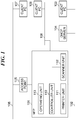
- FIG. 1 is a block diagram schematically showing an arrangement of the MFP 101 as an information processing apparatus according to the embodiment of the present invention.
- the MFP 101 is connected with a client PC 103 and a DHCP (dynamic host configuration protocol) server 104 as communication apparatuses constituting a LAN 102 in a wired infrastructure by a wired cable, not shown.
- the MFP 101 performs wired LAN communication with the client PC 103 and the DHCP server 104.
- the DHCP server 104 allocates an IP address to each of the MFP 101 and the client PC 103.
- the client PC 103 designates an IP address of the MFP 101 allocated by the DHCP server 104 to access to the MFP 101 and starts data communication with the MFP 101.
- the MFP 101 performs wireless LAN communication with a client PC 107 as a communication apparatus constituting a LAN 106 in a wireless infrastructure via an access point 105 communicatively connected to the MFP 101. Further, the MFP 101 itself functions as an access point and directly performs wireless communication with a client PC 109 as a communication apparatus constituting a LAN 108.
- the MFP 101 has a plurality of lines, and in the present embodiment, an explanation will be given of an arrangement in which the MFP 101 has one main line and one sub line as an example.
- the MFP 101 is able to concurrently operate the wired infrastructure and the wireless infrastructure, and in this embodiment, one of the wired infrastructure and the wireless infrastructure is used as the main line, and the other is used as the sub line.
- the MFP 101 has a controller unit 110, a printer unit 111, a scanner unit 112, and an operating unit 113, and the controller unit 110 is connected with the printer unit 111, the scanner unit 112, and the operating unit 113.
- the controller unit 110 collectively controls overall operation of the MFP 101.
- the printer unit 111 performs printing on a sheet based on print data received from the communication apparatuses such as the client PCs 103, 107, and 109.
- the scanner unit 112 scans an original and generates image data.
- the operating unit 113 has a display unit and a plurality of operation keys, not shown. For example, the operating unit 113 displays an operation screen for configuring settings on the MFP 101 on the display unit and receives an instruction input by a user operating the operation keys.
- FIG. 2 is a block diagram schematically showing an arrangement of the controller unit 110 appearing in FIG. 1 .
- the controller unit 110 has a CPU 201, a DRAM 202, an I/O controller 202, a SATA I/F 204, an HDD 205, a network I/F 206, a wired LAN device 207, and a wireless LAN device 208.
- the controller unit 110 also has a panel I/F 209, a printer I/F 210, and a scanner I/F 211.
- the CPU 201 is connected with the DRAM 202 and the I/O controller 203.
- the I/O controller 203, the SATA I/F 204, the network I/F 206, the panel I/F 209, the printer I/F 210, and the scanner I/F 211 are connected with one another via a bus 212.
- the SATA I/F 204 is connected with the HDD 205.
- the network I/F 206 is connected with the wired LAN device 207 and the wireless LAN device 208.
- the CPU 201 carries out a computation process for performing various controls in the controller unit 110 and transmits various control instructions to the I/O controller 203.
- the DRAM 202 is used as a work area for the CPU 201 and as a temporal storage area of various types of data.
- the I/O controller 203 transfers a control instruction by the CPU 201 to component elements connected via the bus 212.
- the SATA I/F 204 performs control to write data in the HDD 205 and performs controls to read out data stored in the HDD 205 in accordance with the control instruction by the CPU 201.
- the HDD 205 stores programs for implementing functions of the MFP 101, image data, and the like.
- the network I/F 206 controls each of the wired LAN device 207 and the wireless LAN device 208 in accordance with the control instruction by the CPU 201.
- the wired LAN device 207 controls wired LAN communication performed with the client PC 103 and the like constituting the LAN 102 in the wired infrastructure.
- the wireless LAN device 208 has a wireless infrastructure mode and a wireless access point mode. In the wireless infrastructure mode, wireless LAN communication is performed via the client PC 107 and the access point 105 constituting the LAN 106 in the wireless infrastructure. In the wireless access point mode, the MFP 101 functions as an access point and directly performs the wireless communication with the client PC 109 constituting the LAN 108.
- the wireless communication in the wireless access point mode is defined as "a Wireless Direct".
- the panel I/F 209 performs display control in the operating unit 113 in accordance with the control instruction by the CPU 201 and transfers a content input by the user operating the operating unit 113 to the CPU 201.
- the printer I/F 210 causes the printer unit 111 to carry out a printing process in accordance with the control instruction by the CPU 201.
- the scanner I/F 211 causes the scanner unit 112 to carry out a scanning process in accordance with the control instruction by the CPU 201.
- FIG. 3 is a block diagram schematically showing an arrangement of software modules controlled by the controller unit 110 appearing in FIG. 1 .
- the MFP 101 has an operation control module 301, a data storage module 302, a network setting module 303, a DHCP control module 304, and a TCP/IP control module 305.
- the MFP 101 also has a WPA (Wi-Fi protected access) control module 306, a job control module 307, an image processing module 308, a print processing module 309, and a readout processing module 310. Controls on the above-described modules are performed by the CPU 201 implementing programs stored in the HDD 205.
- WPA Wi-Fi protected access
- the operation control module 301 performs display control on the display screen and the like in the operating unit 113 and receives operations by the user on the operation screen and the operation keys.
- the data storage module 302 performs controls to write data such as a setting value into the HDD 205 and read out data stored in the HDD 205.
- the network setting module 303 performs control on network settings of the MFP 101 and requests the DHCP control module 304 and the WPA control module 306 and the like to carry out processing. For example, when the user configures a setting to use the IP address allocated by the DHCP server 104 as address information of the MFP 101, the network setting module 303 requests the DHCP control module 304 to carry out the following processing.
- the DHCP control module 304 controls a process of allocating an IP address in accordance with a protocol defined as a DHCP by RFC 2131.
- the TCP/IP control module 305 carries out a process of sending/receiving a network packet.
- the WPA control module 306 carries out a wireless access authentication process in accordance with a predetermined encryption method, for example, a WPA protocol.
- a WPA protocol for example, a WPA protocol.
- the job control module 307 performs control on execution of a job and issues an execution instruction relating to a job with respect to the image processing module 308, the print processing module 309 and the readout processing module 310.
- the image processing module 308 carries out image processing such as processing of image data into data formats suitable for respective usages.
- the print processing module 309 controls the printer unit 111 to carry out the printing process.
- the readout processing module 310 controls the scanner unit 112 to carry out the scanning process.
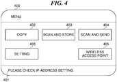
- the menu screen 400 is an operation screen for the user to select functions of the MFP 101.
- the menu screen 400 has an information notifying area 401, a copy button 402, a scan and store button 403, a scan and send button 404, a wireless access point button 405, and a setting button 406.
- a notification to the user is displayed.
- the copy button 402 is selected when the user uses the copying function.
- the scan and store button 403 is selected when the user uses a function to store image data obtained by the MFP 101 performing scanning.
- the scan and send button 404 is selected when the user uses a function to send the image data obtained by the MFP 101 performing scanning to the communication apparatus.
- the wireless access point button 405 is selected when the MFP 101 is to sifted into the wireless access point mode.
- the wireless access point button 405 is displayed on the menu screen 400 when a wireless access point mode enabling setting 1301 in FIG. 13 , to be described later, is set to ON.
- a start setting screen 500 in FIG. 5A to be described later, is displayed on the operating unit 113.
- the setting button 406 is selected when the user changes settings on the MFP 101.
- a setting screen 600 in FIG. 6 is displayed on the operating unit 113.
- the start setting screen 500 in FIG. 5A is a setting screen for instructing start of the Wireless Direct.
- a user selects a start button 501 in the start setting screen 500, an instruction to start shifting to the wireless access point mode is issued to the network setting module 303.
- the MFP 101 operates as an access point and becomes ready to start the Wireless Direct with the client PC 109 and the like.
- the user can instruct to start shifting to the wireless access point mode by an easy operation of merely selecting the wireless access point button 405 in the menu screen 400 and selecting the start button 501 in the start setting screen 500.
- a setting information screen 502 in FIG. 5B is displayed on the operating unit 113.
- setting information such as an SSID, PSK, or the like required for communicatively connecting the client PC 109 and the like with the MFP 101 as the access point.
- an end button 503 in the setting information screen 502 an instruction to end the wireless access point mode is issued to the network setting module 303.
- the MFP 101 ends the Wireless Direct with the client PC 109.
- the setting screen 600 in FIG. 6 is an operation screen for guiding the user to a setting screen for configuring detailed information of each setting and has a device setting button 601, a user setting button 602, and a network line setting button 603.
- the device setting button 601 is an operation button for displaying a device setting screen, not shown, for configuring setting on devices of the MFP 101.
- the user setting button 602 is an operation button for displaying a user setting screen, not shown, for configuring settings on users of the MFP 101.
- the network line setting button 603 is an operation button for displaying a network setting screen in FIG. 7 for configuring network settings on the MFP 101.
- the network setting screen 700 in FIG. 7 is an operation screen for guiding the user to a setting screen for configuring a setting on detailed information of the network settings.
- the network setting screen 700 has an interface selection button 701, a main line setting button 702, a sub line setting button 703, a wireless setting button 704, a wireless access point setting button 705, and a setting reflection button 706.
- the interface selection button 701 is an operation button for displaying an interface selection screen 800 in FIG. 8 , to be described later.
- the main line setting button 702 is an operation button for displaying a main line setting screen 900 in FIG. 9 , to be described later.
- the sub line setting button 703 is an operation button for displaying a sub line setting screen 1000 in FIG. 10 , to be described later.
- the wireless setting button 704 is an operation button for displaying a wireless setting screen 1100 in FIG. 11 , to be described later.
- the wireless access point setting button 705 is an operation button for displaying a wireless access point setting screen 1300 in FIG. 13 , to be described later.
- the setting reflection button 706 is an operation button for storing a setting value set by the user in the HDD 205 and instructing reflection of the settings to the network setting module 303.
- the interface selection screen 800 in FIG. 8 is a setting screen for configuring a setting on the wired infrastructure and the wireless infrastructure in the MFP 101.
- Settings in the interface selection screen 800 are to be configured by an administrator or the like of the MFP 101, and the settings are not changed frequently.
- wired-only 801 is set to ON
- the MFP 101 uses the wired infrastructure only.
- wireless-only 802 is set to ON
- the MFP 101 uses the wireless infrastructure only.
- wired (main) + wireless (sub) 803 is set to ON, the MFP 101 uses the wired infrastructure as a main line and uses the wireless infrastructure as a sub line.
- the interface selection screen 800 only one of the wired-only 801, the wireless-only 802, and the wired (main) + wireless (sub) 803 can be set to ON.
- an OK button 804 is selected, a setting value set in the interface selection screen 800 is stored in the DD 205. It should be noted that in the present embodiment, the setting on the wireless infrastructure is not associated with the setting on the Wireless Direct, and the setting value set in the interface selection screen 800 does not affects the setting on the Wireless Direct.
- the main line setting screen 900 in FIG. 9 is an operation screen for setting address information of the main line of the MFP 101.
- an IP address input section 901 a subnet mask input section 902, and a default gateway input section 903, the user is able to input an arbitral IP address, subnet mask, and default gateway, respectively.
- a DHCP selection section 904 is set ON, a setting to obtain an IP address included in the address information of the main line from the DHCP server on the main line network is configured.
- an Auto IP (automatic private IP addressing) selection section 905 is set to ON, a setting to determine an IP address included in the address information of the main line by an Auto IP protocol is configured.
- an OK button 906 is selected, the setting values set in the main line setting screen 900 are stored in the HDD 205.
- the sub line setting screen 1000 in FIG. 10 is an operation screen for setting address information of the sub line of the MFP 101.
- the user is able to input arbitral IP address and subnet mask in an IP address input section 1001 and a subnet mask input section 1002.
- a DHCP selection section 1003 is set to ON, a setting to obtain an IP address included in the address information of the sub line from the DHCP server on the network of the subline is configured.
- an OK button 1004 is selected, setting values set in the sub line setting screen 1000 are stored in the HDD 205. It should be noted that in the present embodiment, in order to concurrently use the plurality of lines, a part of functions on the sub line side is limited; for example, the sub line cannot use a default gateway and an Auto IP.
- the sub line is used, for example, as a line with which communication is performed within a network set in advance.
- the main line is used as a line with which communication is performed via a plurality of networks including an external network by using the default gateway other than the network set in advance.
- the sub line setting screen 1000 does not have a setting item for using the default gateway and the Auto IP.
- functions such as DNS, 802.1x, IPsec, IP filter, port filter, MAC address filter, SMB, HTTP, WebDAV, and FTP cannot be used on the subline side.
- the wireless setting screen 1100 in FIG. 11 is an operation screen for configuring a authentication setting in the wireless infrastructure mode.
- An SSID of an access point to which the user wish to access and a key corresponding to the SSID is input to an SSID input section 1101 and a PSK input section 1102, respectively.
- an access point selection screen 1200 in FIG. 12 for selecting an access point is displayed on the operating unit 113.
- an OK button 1104 is selected, setting values set in the wireless setting screen 1100 are stored in the HDD 205.
- the access point selection screen 1200 in FIG. 12 is an operation screen for setting an access point to be used by the MFP 101.
- a list of access points which can be used by the MFP 101 is displayed on a search result display section 1201.
- the access point 105 for example, is selected from the list of the access points displayed on the search result display section 1201, and information indicative of the access point 105 is stored in the HDD 205.
- the wireless setting screen 1100 with the SSID of the access point 105 is set in the SSID input unit 101 is then displayed on the operating unit 113.
- An wireless access point setting screen 1300 in FIG. 13 is a setting screen for configuring a setting on the wireless access point mode.
- the settings in the wireless access point setting screen 1300 are also configured by the administrator of the MFP 101 and are not frequently changed.
- a wireless access point mode enabling setting 1301 is set to ON, the wireless access point mode of the MFP 101 is enabled.
- the menu screen 400 displayed on the operating unit 113 with the wireless access point mode enabled includes the wireless access point button 405 for displaying the start setting screen 500 for instructing shifting to the wireless access point mode.
- the wireless access point mode enabling setting 1301 is set to OFF, the wireless access point mode of the MFP 101 is disabled.
- the menu screen 400 displayed on the operating unit 113 with the wireless access point mode disabled does not include the wireless access point button 405.
- an OK button 1302 is selected, setting values set in the wireless access point setting screen 1300 are stored in the HDD 205, and a screen on the operating unit 113 is switched to the network setting screen 700.
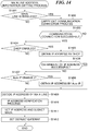
- FIG. 14 is a flowchart showing a procedure of an address information setting process for the main line carried out by the network setting module 303 appearing in FIG. 3 .
- the process in FIG. 14 is carried out by the CPU 201 implementing a program stored in the HDD 205.
- the process in FIG. 14 is also carried out when a system of the MFP 101 is started or when the setting reflection button 706 in the network setting screen 700 is selected.
- the process in FIG. 14 is carried out on an assumption that at least the settings on the screens in FIGS. 8, 9 and 11 are already configured.
- the network setting module 303 determines whether the main line is wireless (step S1401). In step S1401, when the setting value indicative of the "wireless-only 802" is stored in the HDD 205, the network setting module 303 determines that the main line is wireless. on the other hand, when the setting value indicative of either of the "wired-only 801" or “wired (main) + wireless (sub) 803" is stored in the HDD 205, the network setting module 303 determines that the main line is not wireless.
- the network setting module 303 carries out a communication connecting process with an access point set on the wireless setting screen 1100, for example, the access point 105 (step S1402).
- the network setting module 303 requests the WPA control module 306 to carry out the process.
- the WPA control module 306 obtains an SSID and a PSK of the access point 105 from the data storage module 320 and transmits an authentication request generated based on the obtained PSK to the access point 105.
- the WPA control module 306 receives a determination result as to connection possible/impossible from the access point 105.
- the network setting module 303 determines whether the communication connection with the access point 105 was successful (step S1403). In step S1403, when the received determination result indicates connection possible, the network setting module 303 determines that the communication connection with the access point 105 was successful. On the other hand, the received determination result indicates connection impossible, the network setting module 303 determines that the communication connection with the access point 105 was unsuccessful.
- step 1403 As a result of the determination in step 1403, when the communication connection with the access point 105 was unsuccessful, the network setting module 303 terminates the present process.
- the network setting module 303 determines whether the DHCP is enabled (step S1404).
- step S1404 when a setting value indicating that the DHCP selection section 904 is ON is stored in the HDD 205, the network setting module 303 determines that the DHCP is enabled. On the other hand, when a setting value indicating that the DHCP selection section 904 is OFF, the network setting module 303 determines that the DHCP is disabled.
- the network setting module 303 obtains an IP address by the DHCP (step S1405).
- the network setting module 303 requests the DHCP control module 304 to carry out the process.
- the DHCP module 304 searches the DHCP server on the network of the main line of the MFP 101 in accordance with the DHCP protocol.
- the DHCP control module 304 obtains an IP address allocated by the searched DHCP server and registers usage of the obtained IP address to the DHCP server.
- the network setting module 303 determines whether the obtainment of the IP address by the DHCP was successful (step S1406).
- step S1406 when the obtainment of the IP address by the DHCP was successful, the network setting module 303 carries out a process in step S1409, to be described later.
- step S1407 when a setting value indicating that the Auto IP selection section 905 is ON is stored in the HDD 205, the network setting module 303 determines that the Auto IP is enabled. On the other hand, when a setting value indicating that the Auto IP selection section 905 is OFF is stored in the HDD 205, the network setting module 303 determines that the Auto IP is disabled.
- the network setting module 303 obtains an IP address by the Auto IP (step S1408).
- the network setting module 303 carries out a selection process in which it selects in a random manner one IP address from an IP address range prescribed in advance for the Auto IP.
- the network setting module 303 also carries out a confirmation process in which it confirms that no communication apparatus to which the IP address is set exists on the network of the main line by using the ARP protocol.
- the network setting module 303 repeats the above selection process and the above confirmation process until an IP address which is not used by all communication apparatus on the network of the main lime.
- the network setting module 303 decides the address information of the main line of the MFP 101 (step 1409).
- the network setting module 303 decides the IP address obtained by the searched DHCP server, a subnet mask corresponding to the IP address, and the default gateway as the address information of the main line.
- the network setting module 303 decides that the IP address obtained by the Auto IP, a subnet mask corresponding to the IP address, and the default gateway as the address information of the main line.
- the network setting module 303 decides a disabled address (0. 0. 0.
- the network setting module 303 decides the setting values input to the IP address input section 901, the subnet mask input section 902, and the default gateway input section 903 as the address information of the main line.
- the network setting module 303 then verifies the IP address of the decided address information (step S1410). As a result of the verification, when the IP address is a disabled IP address, a message and the like which prompts the user to confirm an IP address on the operating unit 113.
- the network setting module 303 sets the IP address and the subnet mask of the decided address information to the TCP/IP control module 305 (step S1411).
- the network setting module 303 sets the default gateway of the decided address information to the TCP/IP control module 305 (step S1412) and terminates the present process.
- FIG. 15 is a flowchart showing a procedure of a sub line address information setting process carried out by the network setting module 303 appearing in FIG. 3 .
- the process of FIG. 15 is carried out by the CPU 201 implementing a program stored in the HDD 205, and carried out when the setting value indicative of the "wired (main) + wireless (sub) 803" was selected is store in the HDD 205, and the process in FIG. 14 was completed.
- the network setting module 303 carries out the above described communication connection process with an access point set on the wireless setting screen 1100, for example, the access point 105 (step S1501). The network setting module 303 then determines whether the communication connection with the access point 105 was successful (step S1502).
- step S1502 when the communication connection with the access point 105 was unsuccessful, the network setting module 303 terminates the present process.
- the network setting module 303 determines whether the DHCP is enabled based on the setting value set for the DHCP selection section 904 stored in the HDD 205 (step S1503).
- the network setting module 303 obtains an IP address by the DHCP (step S1504).
- the network setting module 303 accesses to the DHCP server on the network of the sub line and obtains the IP address from the DHCP server.
- the network setting module 303 decides the address information of the sub line of the MFP 101 (step S1505).
- step S1505 when the obtainment of the IP address by the DHCP was successful, the network setting module 303 decides the obtained IP address and a subnet mask corresponding to the IP address as the address information of the sub line.
- the network setting module 303 decides a disabled address (0. 0. 0. 0) and a subnet mask corresponding to the disabled address as the address information of the sub line.
- the network setting module 303 carries out a process in step S1505. At this time, the network setting module 303 decides setting values input in the IP address input section 1001 and the subnet mask input unit 1002 as the address information of the sub line. The network setting module 303 then starts a process of verifying overlap of decided address information of the sub line (step 1506), and determines whether the address information of the sub line overlaps with the address information of the main line (step S1507).
- step S1507 for example, when a sub line network address identified based on the IP address and the subnet mask in the address information of the sub line matches with a main line network address identified based on the IP address and the subnet mask in the address information of the main line, the network setting module 303 determines that the decided the address information of the sub line overlaps with the address information of the main line. On the other hand, when the sub line network address and the main line network address do not match, the network setting module 303 determines that the decided address information of the sub line does not overlap with the address information of the main line.
- the network setting module 303 may determine that the decided address information of the sub line overlaps with the address information of the main line even if the sub line network address does not completely match the main line network address.
- step S1507 when the decided address information of the sub line does not overlap with the address information of the main line, the network setting module 303 verifies the IP address in the decided address information of the sub line (step S1508). The network setting module 303 then sets the IP address and the subnet mask in the decided address information of the sub line to the TCP/IP control module 305 (step S1509), and terminates the present process.
- step S1507 when the decided address information of the sub line overlaps with the address information of the main line, the network setting module 303 displays a message 1601 in FIG. 16 indicating this effect on the operating unit 113 (step S1510).
- the network setting module 303 then disconnects the communication connection with the access point 105 (step S1511). Namely, in the present embodiment, when the address information of the sub line overlaps with the address information of the main line, the sub line is disabled. Thereafter, the network setting module 303 terminates the present process.
- the sub line is disabled. Namely, when the MFP 101 is accessed by a communication apparatus, it is not necessary to identify a line for communicating with the communication apparatus between the main line and the sub line. As a result, even if the same address information is set for the main line and the sub line, it is possible to easily identify a line to be used.
- the main line uses the default gateway. Consequently, a variety of networks including an external network other than the network set in advance can be constructed. As a result, even if the sub line is disabled, it is possible to surely communicate with a communication apparatus which has accessed to the MFP 101 by using the variety of networks.
- the function of the sub line is more limited than that of the main line, and the sub line does not use the default gateway which is used in the main line.
- the main line by which communication through the variety of networks constructed by using the default gateway is performed and the sub line by which communication within a network set in advance is performed are used in different ways.
- FIG. 17 is a flowchart showing a procedure of the wireless access point mode starting process carried out by the network setting module 303 appearing in FIG. 3 .
- the process in FIG. 17 is carried out by the CPU 201 implementing a program stored in the HDD 205, and carried out when the user selects the start button 501 on the start setting screen 500.
- address information for the wireless access point mode specifically, an IP address and a subnet mask are allocated in advance.
- the network setting module 303 requests the WPA control module 306 to generate an SSID and a PSK of the MFP 101 as an access point (step S1701).
- the network setting module 303 requests the WPA control module 306 to set the SSID and the PSK (step S1702).
- the network setting module 303 requests the WPA control module 306 to enable a network interface, not shown, corresponding to the wireless access point mode (step S1703).
- the network setting module 303 then starts a process of verifying overlap between the address information for the wireless access point mode and the address information of the main line (step S1704).
- the network setting module 303 determines whether the address information for the wireless access point mode overlaps with the address information of the main line (step S1705).
- step S1705 a wireless access point mode network address identified by an IP address and a subnet mask in the address information for the wireless access point mode and the above described main line network address are compared with each other.
- step S1705 the determination is performed based on the same determination reference as that in step S1507.
- step S1705 when the address information for the wireless access point mode overlaps with the address information of the main line, the network setting module 303 displays a message 1602 in FIG. 16 indicating this effect on the operating unit 113 (step S1706). Thereafter, the network setting module 303 terminates the present process.
- step S1705 when the address information for the wireless access point mode does not overlap with the address information of the main line, the network setting module 303 starts a process of verifying overlap between the address information for the wireless access point mode and the address information of the sub line (step S1707).
- the network setting module 303 determines whether the address information for the wireless access point mode overlaps with the address information of the sub line (step S1708).
- step S1708 the above described wireless access point mode network address and the above described sub line network address are compared with each other, and the determination is performed based on the same determination reference as that in steps S1507 and S1705.
- step S1708 when the address information for the wireless access point mode overlaps with the address information of the sub line, the network setting module 303 displays a message 1603 in FIG. 16 indicating this effect on the operating unit 113 (step S1709). Thereafter, the network setting module 303 terminates the present process.
- the network setting module 303 sets the address information for the wireless access point mode. Specifically, the network setting module 303 sets an IP address and a subnet mask in the address information for the wireless access point mode to the TCP/IP control module 305 (step S1710). As a result, the MFP 101 can perform the Wireless Direct. Thereafter, the network setting module 303 terminates the present process.
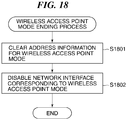
- FIG. 18 is a flowchart showing a procedure of a wireless access point mode ending process carried out by the network setting module 303 appearing in FIG. 3 .
- the process in FIG. 18 is carried out by the CPU 201 implementing a program stored in the HDD 205.
- the process in FIG. 18 is also carried out when the user selects the end button 503 on the setting information screen 502 while the MFP 101 is in the wireless access point mode.
- the network setting module 303 clears address information for the set wireless access point mode, specifically, the IP address and the subnet mask for the wireless access point mode (step S1801).
- the network setting module 303 requests the WPA control module 306 to disable a network interface, not shown, corresponding to the wireless access point mode (step S1802). Subsequently, the network setting module 303 terminates the present process.
- a control may be provided not to accept a starting instruction for the Wireless Direct in the wireless access point mode when the address information for the wireless access point mode overlaps with the address information of either of the main line or the sub line.
- FIG. 19 is a flowchart showing a procedure of a display control process carried out by the network setting module 303 appearing in Fig. 3 .
- the process in FIG. 19 is carried out by the CPU 201 implementing a program stored in the HDD 205.
- the process in FIG. 19 is also carried out when, on the menu screen 400, the user selects the wireless access point button 405 for displaying the start setting screen 500 through which a starting instruction of the Wireless Direct in the wireless access point mode is issued.
- the address information for the wireless access point mode is allocated in advance in the MFP 101.
- the network setting module 303 starts a process of verifying overlap between the address information for the wireless access point mode and the address information of the main line (step S1901).
- the network setting module 303 determines whether the address information for the wireless access point mode overlaps with the address information of the main line (step S1902).
- step S1902 when the address information for the wireless access point mode does not overlap with the address information of the main line, the network setting module 303 starts a process of verifying overlap between the address information for the wireless access point mode and the address information of the sub line (step S1903). The network setting module 303 determines whether the address information for the wireless access point mode overlaps with the address information of the sub line (step S1904).
- step S1904 when the address information for the wireless access point mode does not overlap with the address information of the sub line, the network setting module 303 displays the start setting screen 500 on the operating unit 113 (step S1905). Thereafter, the network setting module 303 terminates the present process.
- the network setting module 303 displays the start setting screen 500 subjected to a process for preventing the user from selecting the start button 501 on the operating unit 113 (step S1906).
- the start button 501 is displayed in an unselectable manner or is not displayed. Thereafter, the network setting module 303 terminates the present process.
- an error message may be displayed on the operating unit 113 before the input address information of the sub line is reflected.
- FIG. 20 is a flowchart showing a procedure of a setting value storing process carried out by the network setting module 303 appearing in FIG. 3 .
- the process in FIG. 20 is carried out by the CPU 201 implementing a program stored in the HDD 205.
- the process in FIG. 20 is also carried out when the user selects the OK button 1004 on the sub line setting screen 1000.
- the network setting module 303 starts a process of verifying overlap between the address information of the sub line (hereinafter, referred to as "the sub line input address information") input on the sub line setting screen 1000 and the address information of the main line (step S2001).
- the network setting module 303 determines whether the sub line input address information overlaps with the address information of the main line (step S2002).
- the network setting module 303 stores the sub line input address information into the HDD 205 (step S2003). Specifically, the network setting module 303 stores an IP address input in the IP address input section 1001 of the sub line setting screen 1000 and a subnet mask input in the sub net mask input section 1002 of the sub line setting screen 1000 into the HDD 205. Thereafter, the network setting module 303 terminates the present process.
- the network setting module 303 displays a message 2101 in FIG. 21 indicating this effect on the operating unit 113 (step S2004). Thereafter, the network setting module 303 terminates the present process.
- the IP address included in the address information of the sub line may be obtained again when the decided address information of the sub line overlaps with the address information of the main line.
- FIG. 22 is a flowchart showing a procedure of a variation of the sub line address information setting process in FIG. 15 .
- the process in FIG. 22 is also carried out by the CPU 201 implementing a program stored in the HDD 205, and carried out when the setting value indicating that the "wired (main) + wireless (sub)" 803 was selected and the above described process in FIG. 14 was terminated. It should be noted that in the process in FIG. 22 , when the decided address information of the sub line overlaps with the address information of the main line as a result of the determination in step S1507 in FIG. 15 , another process is carried out. Therefore, only a description of a process different from that in the process in the FIG. 15 will be explained hereinafter.
- the network setting module 303 provides a notification saying not to accept the obtained IP address to the DSCP server to which the network setting module 303 accessed in step S1504 (step S2201). Specifically, the network setting module 303 sends a DHCPDECLINE to the DHCP server in accordance with the DHCP protocol and provides a notification saying not to use the IP address allocated by the DHCP server. The network setting module 303 then counts the number of retries (step S2202). Specifically, the network setting module 303 increments the number of retries set in advance in the data storage module 302.
- step S2203 determines whether the number of retries has reached an upper limit.
- the network setting module 303 determines that the number of retries has reached the upper limit.
- the network setting module 303 determines that the number of retries has not reached the upper limit.
- step S2203 As a result of the determination in step S2203, when the number of retries has not reached the upper limit, the process returns to step S1503. On the other hand, as a result of the determination in step S2203, when the number of retries has reached the upper limit, the network setting module 303 carries out the processes in step S1510 and subsequent steps.
- the MFP 101 obtains address information of the sub line again. As a result, it is possible to prevent a situation where the address information of the sub line which overlaps with the address information of the main line is set.
- a name of the main line may be replaced with a name such as a primary line and a priority line
- a name of the sub line may be replaced with a name such as a secondary line and an auxiliary line.
- a name of the line may be replaced with a name such as an infrastructure.
- Embodiment(s) of the present invention can also be realized by a computer of a system or apparatus that reads out and executes computer executable instructions (e.g., one or more programs) recorded on a storage medium (which may also be referred to more fully as a 'non-transitory computer-readable storage medium') to perform the functions of one or more of the above-described embodiment(s) and/or that includes one or more circuits (e.g., application specific integrated circuit (ASIC)) for performing the functions of one or more of the above-described embodiment(s), and by a method performed by the computer of the system or apparatus by, for example, reading out and executing the computer executable instructions from the storage medium to perform the functions of one or more of the above-described embodiment(s) and/or controlling the one or more circuits to perform the functions of one or more of the above-described embodiment(s).
- computer executable instructions e.g., one or more programs
- a storage medium which may also be referred to more fully as
- the computer may comprise one or more processors (e.g., central processing unit (CPU), micro processing unit (MPU)) and may include a network of separate computers or separate processors to read out and execute the computer executable instructions.
- the computer executable instructions may be provided to the computer, for example, from a network or the storage medium.
- the storage medium may include, for example, one or more of a hard disk, a random-access memory (RAM), a read only memory (ROM), a storage of distributed computing systems, an optical disk (such as a compact disc (CD), digital versatile disc (DVD), or Blu-ray Disc (BD)TM), a flash memory device, a memory card, and the like.
- An information processing apparatus which is able to identify a line to be used even if same address information is set for a plurality of lines.
- one of a wired I/F and a wireless I/F is used as a main line and the other is used as a sub line.
- Whether a network address of an IP address of the sub line overlaps with a network address of an IP address of the main line is determined. In a case where it is determined that the network address of the IP address of the sub line overlaps with the network address of the IP address of the main line, the sub line is disabled.
Abstract
Description
- The present invention relates to an information processing apparatus, a control method therefor, and a storage medium.
- Generally, a plurality of different networks is used in different ways in an office and so on in terms of securing a security quality and the like required for a network. An MFP as an information processing apparatus employed in an office has a plurality of lines, and the plurality of lines uses different networks, respectively. For example, the MFP uses a network by a line and uses another network different from the network by another line. In the MFP of this type, address information such as an IP address for accessing each line by a communication apparatus is set for the each line, and the address information of the each line is different from each other. The MFP identifies a line for performing communication with the communication apparatus from among the plurality of lines based on address information designated by the communication apparatus at a time of access (for example, see, Japanese Laid-Open Patent Publication (Kokai) No.
2003-319461 - However, when the same address information is set for the plurality of lines, the conventional MFP cannot discriminate each line based on the address information. As a result, the conventional MFP cannot identify a line for performing the communication with the communication apparatus from among the plurality of lines based on the address information designated by the communication apparatus at the time of access.
- The present invention provides an information processing apparatus which is able to identify a line to be used even if same address information is set for a plurality of lines, a control method therefor, and a storage medium.
- Accordingly, a first aspect of the present invention provides an information processing apparatus as specified in
claims 1 to 7. - A second aspect of the present invention provides a control method as specified in claim 8.
- A third aspect of the present invention provides a non-transitory computer-readable storage medium as specified in claim 9.
- According to the present invention, the line to be used can be identified even if the same address information is set for the plurality of lines.
- Further features of the present invention will become apparent from the following description of exemplary embodiments (with reference to the attached drawings).
-
-
FIG. 1 is a block diagram schematically showing an arrangement of an MFP as an information processing apparatus according to an embodiment of the present invention. -
FIG. 2 is a block diagram schematically showing an arrangement of a controller unit appearing inFIG. 1 . -
FIG. 3 is a block diagram schematically showing an arrangement of software modules controlled by the controller unit appearing inFIG. 1 . -
FIG. 4 is a view showing an example of a menu screen displayed on an operating unit appearing inFIG. 1 . -
FIGS. 5A and 5B are views showing examples of screens for instructing start and end of a wireless access point mode in the MFP appearing inFIG. 1 . -
FIG. 6 is a view showing an example of a setting screen displayed on the operating unit appearing inFIG. 1 . -
FIG. 7 is a view showing an example of a network setting screen displayed on the operating unit appearing inFIG. 1 . -
FIG. 8 is a view showing an example of an interface selection screen displayed on the operating unit appearing inFIG. 1 . -
FIG. 9 is a view showing an example of a main line setting screen displayed on the operating unit appearing inFIG. 1 . -
FIG. 10 is a view showing an example of a sub line setting screen displayed on the operating unit appearing inFIG. 1 . -
FIG. 11 is a view showing an example of a wireless setting screen displayed on the operating unit appearing inFIG. 1 . -
FIG. 12 is a view showing an example of an access point selection screen displayed on the operating unit appearing inFIG. 1 . -
FIG. 13 is a view showing an example of a wireless access point setting screen displayed on the operating unit appearing inFIG. 1 . -
FIG. 14 is a flowchart showing a procedure of a main line address information setting process carried out by a network setting module appearing inFIG. 3 . -
FIG. 15 is a flowchart showing a procedure of a sub line address information setting process carried out by the network setting module appearing inFIG. 3 . -
FIG. 16 is a view showing examples of messages displayed on the operating unit appearing inFIG. 1 . -
FIG. 17 is a flowchart showing a procedure of a wireless access point mode starting process carried out by the network setting module appearing inFIG. 3 . -
FIG. 18 is a flowchart showing a procedure of a wireless access point mode ending process carried out by the network setting module appearing inFIG. 3 . -
FIG. 19 is a flowchart showing a procedure of a display control process carried out by the network setting module appearing inFIG. 3 . -
FIG. 20 is a flowchart showing a procedure of a setting value storing process carried out by the network setting module appearing inFIG. 3 . -
FIG. 21 is a view showing examples displayed on the operating unit appearing inFIG. 1 . -
FIG. 22 is a flowchart showing a procedure of a variation of the sub line address information setting process inFIG. 15 . - An embodiment of the present invention will now be described with reference to the accompanying drawings. In the present embodiment, a description will be given of a case where the present invention is applied to an MFP as an information processing apparatus, but the present invention may be applied not only to the MFP but to a communication apparatus such as a PC equipped with a plurality of liens.
-
FIG. 1 is a block diagram schematically showing an arrangement of theMFP 101 as an information processing apparatus according to the embodiment of the present invention. - In
FIG. 1 , the MFP 101 is connected with a client PC 103 and a DHCP (dynamic host configuration protocol)server 104 as communication apparatuses constituting aLAN 102 in a wired infrastructure by a wired cable, not shown. The MFP 101 performs wired LAN communication with the client PC 103 and the DHCPserver 104. In theLAN 102, the DHCPserver 104 allocates an IP address to each of theMFP 101 and the client PC 103. For example, the client PC 103 designates an IP address of theMFP 101 allocated by theDHCP server 104 to access to the MFP 101 and starts data communication with theMFP 101. The MFP 101 performs wireless LAN communication with a client PC 107 as a communication apparatus constituting aLAN 106 in a wireless infrastructure via anaccess point 105 communicatively connected to the MFP 101. Further, the MFP 101 itself functions as an access point and directly performs wireless communication with a client PC 109 as a communication apparatus constituting aLAN 108. - The MFP 101 has a plurality of lines, and in the present embodiment, an explanation will be given of an arrangement in which the MFP 101 has one main line and one sub line as an example. The MFP 101 is able to concurrently operate the wired infrastructure and the wireless infrastructure, and in this embodiment, one of the wired infrastructure and the wireless infrastructure is used as the main line, and the other is used as the sub line.
- Next, an explanation will be given of the arrangement of the MFP 101. The MFP 101 has a
controller unit 110, aprinter unit 111, ascanner unit 112, and anoperating unit 113, and thecontroller unit 110 is connected with theprinter unit 111, thescanner unit 112, and theoperating unit 113. - The
controller unit 110 collectively controls overall operation of the MFP 101. Theprinter unit 111 performs printing on a sheet based on print data received from the communication apparatuses such as theclient PCs scanner unit 112 scans an original and generates image data. Theoperating unit 113 has a display unit and a plurality of operation keys, not shown. For example, theoperating unit 113 displays an operation screen for configuring settings on theMFP 101 on the display unit and receives an instruction input by a user operating the operation keys. -
FIG. 2 is a block diagram schematically showing an arrangement of thecontroller unit 110 appearing inFIG. 1 . - In
FIG. 2 , thecontroller unit 110 has aCPU 201, aDRAM 202, an I/O controller 202, a SATA I/F 204, anHDD 205, a network I/F 206, awired LAN device 207, and awireless LAN device 208. Thecontroller unit 110 also has a panel I/F 209, a printer I/F 210, and a scanner I/F 211. TheCPU 201 is connected with theDRAM 202 and the I/O controller 203. The I/O controller 203, the SATA I/F 204, the network I/F 206, the panel I/F 209, the printer I/F 210, and the scanner I/F 211 are connected with one another via abus 212. The SATA I/F 204 is connected with theHDD 205. The network I/F 206 is connected with the wiredLAN device 207 and thewireless LAN device 208. - The
CPU 201 carries out a computation process for performing various controls in thecontroller unit 110 and transmits various control instructions to the I/O controller 203. TheDRAM 202 is used as a work area for theCPU 201 and as a temporal storage area of various types of data. The I/O controller 203 transfers a control instruction by theCPU 201 to component elements connected via thebus 212. The SATA I/F 204 performs control to write data in theHDD 205 and performs controls to read out data stored in theHDD 205 in accordance with the control instruction by theCPU 201. TheHDD 205 stores programs for implementing functions of theMFP 101, image data, and the like. - The network I/
F 206 controls each of the wiredLAN device 207 and thewireless LAN device 208 in accordance with the control instruction by theCPU 201. The wiredLAN device 207 controls wired LAN communication performed with theclient PC 103 and the like constituting theLAN 102 in the wired infrastructure. Thewireless LAN device 208 has a wireless infrastructure mode and a wireless access point mode. In the wireless infrastructure mode, wireless LAN communication is performed via theclient PC 107 and theaccess point 105 constituting theLAN 106 in the wireless infrastructure. In the wireless access point mode, theMFP 101 functions as an access point and directly performs the wireless communication with theclient PC 109 constituting theLAN 108. Hereinafter, the wireless communication in the wireless access point mode is defined as "a Wireless Direct". - The panel I/
F 209 performs display control in theoperating unit 113 in accordance with the control instruction by theCPU 201 and transfers a content input by the user operating theoperating unit 113 to theCPU 201. The printer I/F 210 causes theprinter unit 111 to carry out a printing process in accordance with the control instruction by theCPU 201. The scanner I/F 211 causes thescanner unit 112 to carry out a scanning process in accordance with the control instruction by theCPU 201. -
FIG. 3 is a block diagram schematically showing an arrangement of software modules controlled by thecontroller unit 110 appearing inFIG. 1 . - In
FIG. 3 , theMFP 101 has anoperation control module 301, adata storage module 302, anetwork setting module 303, aDHCP control module 304, and a TCP/IP control module 305. TheMFP 101 also has a WPA (Wi-Fi protected access)control module 306, ajob control module 307, animage processing module 308, aprint processing module 309, and areadout processing module 310. Controls on the above-described modules are performed by theCPU 201 implementing programs stored in theHDD 205. - The
operation control module 301 performs display control on the display screen and the like in theoperating unit 113 and receives operations by the user on the operation screen and the operation keys. Thedata storage module 302 performs controls to write data such as a setting value into theHDD 205 and read out data stored in theHDD 205. Thenetwork setting module 303 performs control on network settings of theMFP 101 and requests theDHCP control module 304 and theWPA control module 306 and the like to carry out processing. For example, when the user configures a setting to use the IP address allocated by theDHCP server 104 as address information of theMFP 101, thenetwork setting module 303 requests theDHCP control module 304 to carry out the following processing. TheDHCP control module 304 controls a process of allocating an IP address in accordance with a protocol defined as a DHCP by RFC 2131. The TCP/IP control module 305 carries out a process of sending/receiving a network packet. When receiving a request from thenetwork setting module 303, theWPA control module 306 carries out a wireless access authentication process in accordance with a predetermined encryption method, for example, a WPA protocol. It should be note that although in the present embodiment, an explanation will be given of a case where a WPA-PSK encryption method is used when the wireless LAN communication is performed, the encryption method is not limited to this. For example, the encryption method may be a WEP, WPA-EAP or the like, and the encryption method may not be used in the wireless LAN communication. - The
job control module 307 performs control on execution of a job and issues an execution instruction relating to a job with respect to theimage processing module 308, theprint processing module 309 and thereadout processing module 310. Upon receiving the execution instruction from thejob control module 307, theimage processing module 308 carries out image processing such as processing of image data into data formats suitable for respective usages. Upon receiving the execution instruction from thejob control module 307, theprint processing module 309 controls theprinter unit 111 to carry out the printing process. Upon receiving the execution instruction from thejob control module 307, thereadout processing module 310 controls thescanner unit 112 to carry out the scanning process. - Next, an explanation will be given of a
menu screen 400 inFIG. 4 displayed on theoperating unit 113. Themenu screen 400 is an operation screen for the user to select functions of theMFP 101. Themenu screen 400 has aninformation notifying area 401, acopy button 402, a scan andstore button 403, a scan and sendbutton 404, a wirelessaccess point button 405, and asetting button 406. In theinformation notifying area 401, a notification to the user is displayed. Thecopy button 402 is selected when the user uses the copying function. The scan andstore button 403 is selected when the user uses a function to store image data obtained by theMFP 101 performing scanning. The scan and sendbutton 404 is selected when the user uses a function to send the image data obtained by theMFP 101 performing scanning to the communication apparatus. The wirelessaccess point button 405 is selected when theMFP 101 is to sifted into the wireless access point mode. The wirelessaccess point button 405 is displayed on themenu screen 400 when a wireless access point mode enabling setting 1301 inFIG. 13 , to be described later, is set to ON. When the user selects the wirelessaccess point button 405, astart setting screen 500 inFIG. 5A , to be described later, is displayed on theoperating unit 113. Thesetting button 406 is selected when the user changes settings on theMFP 101. When the user selects thesetting button 406 in themenu screen 400, asetting screen 600 inFIG. 6 , to be described later, is displayed on theoperating unit 113. - The
start setting screen 500 inFIG. 5A is a setting screen for instructing start of the Wireless Direct. When a user selects astart button 501 in thestart setting screen 500, an instruction to start shifting to the wireless access point mode is issued to thenetwork setting module 303. As a result, theMFP 101 operates as an access point and becomes ready to start the Wireless Direct with theclient PC 109 and the like. Namely, in the present embodiment, the user can instruct to start shifting to the wireless access point mode by an easy operation of merely selecting the wirelessaccess point button 405 in themenu screen 400 and selecting thestart button 501 in thestart setting screen 500. - When the user selects the
start button 501, a settinginformation screen 502 inFIG. 5B is displayed on theoperating unit 113. In the settinginformation screen 502, setting information such as an SSID, PSK, or the like required for communicatively connecting theclient PC 109 and the like with theMFP 101 as the access point. When the user selects anend button 503 in the settinginformation screen 502, an instruction to end the wireless access point mode is issued to thenetwork setting module 303. As a result, theMFP 101 ends the Wireless Direct with theclient PC 109. - The
setting screen 600 inFIG. 6 is an operation screen for guiding the user to a setting screen for configuring detailed information of each setting and has adevice setting button 601, auser setting button 602, and a networkline setting button 603. Thedevice setting button 601 is an operation button for displaying a device setting screen, not shown, for configuring setting on devices of theMFP 101. Theuser setting button 602 is an operation button for displaying a user setting screen, not shown, for configuring settings on users of theMFP 101. The networkline setting button 603 is an operation button for displaying a network setting screen inFIG. 7 for configuring network settings on theMFP 101. - The
network setting screen 700 inFIG. 7 is an operation screen for guiding the user to a setting screen for configuring a setting on detailed information of the network settings. Thenetwork setting screen 700 has aninterface selection button 701, a mainline setting button 702, a subline setting button 703, awireless setting button 704, a wireless accesspoint setting button 705, and asetting reflection button 706. Theinterface selection button 701 is an operation button for displaying aninterface selection screen 800 inFIG. 8 , to be described later. The mainline setting button 702 is an operation button for displaying a mainline setting screen 900 inFIG. 9 , to be described later. The subline setting button 703 is an operation button for displaying a subline setting screen 1000 inFIG. 10 , to be described later. Thewireless setting button 704 is an operation button for displaying awireless setting screen 1100 inFIG. 11 , to be described later. The wireless accesspoint setting button 705 is an operation button for displaying a wireless accesspoint setting screen 1300 inFIG. 13 , to be described later. The settingreflection button 706 is an operation button for storing a setting value set by the user in theHDD 205 and instructing reflection of the settings to thenetwork setting module 303. - The
interface selection screen 800 inFIG. 8 is a setting screen for configuring a setting on the wired infrastructure and the wireless infrastructure in theMFP 101. Settings in theinterface selection screen 800 are to be configured by an administrator or the like of theMFP 101, and the settings are not changed frequently. When wired-only 801 is set to ON, theMFP 101 uses the wired infrastructure only. When wireless-only 802 is set to ON, theMFP 101 uses the wireless infrastructure only. When wired (main) + wireless (sub) 803 is set to ON, theMFP 101 uses the wired infrastructure as a main line and uses the wireless infrastructure as a sub line. In theinterface selection screen 800, only one of the wired-only 801, the wireless-only 802, and the wired (main) + wireless (sub) 803 can be set to ON. When anOK button 804 is selected, a setting value set in theinterface selection screen 800 is stored in theDD 205. It should be noted that in the present embodiment, the setting on the wireless infrastructure is not associated with the setting on the Wireless Direct, and the setting value set in theinterface selection screen 800 does not affects the setting on the Wireless Direct. - The main
line setting screen 900 inFIG. 9 is an operation screen for setting address information of the main line of theMFP 101. To an IPaddress input section 901, a subnetmask input section 902, and a default gateway input section 903, the user is able to input an arbitral IP address, subnet mask, and default gateway, respectively. When a DHCP selection section 904 is set ON, a setting to obtain an IP address included in the address information of the main line from the DHCP server on the main line network is configured. When an Auto IP (automatic private IP addressing)selection section 905 is set to ON, a setting to determine an IP address included in the address information of the main line by an Auto IP protocol is configured. When anOK button 906 is selected, the setting values set in the mainline setting screen 900 are stored in theHDD 205. - The sub
line setting screen 1000 inFIG. 10 is an operation screen for setting address information of the sub line of theMFP 101. The user is able to input arbitral IP address and subnet mask in an IPaddress input section 1001 and a subnetmask input section 1002. When a DHCP selection section 1003 is set to ON, a setting to obtain an IP address included in the address information of the sub line from the DHCP server on the network of the subline is configured. When anOK button 1004 is selected, setting values set in the subline setting screen 1000 are stored in theHDD 205. It should be noted that in the present embodiment, in order to concurrently use the plurality of lines, a part of functions on the sub line side is limited; for example, the sub line cannot use a default gateway and an Auto IP. For this reason, in the present embodiment, the sub line is used, for example, as a line with which communication is performed within a network set in advance. On the other hand, the main line is used as a line with which communication is performed via a plurality of networks including an external network by using the default gateway other than the network set in advance. The subline setting screen 1000 does not have a setting item for using the default gateway and the Auto IP. Besides, functions such as DNS, 802.1x, IPsec, IP filter, port filter, MAC address filter, SMB, HTTP, WebDAV, and FTP cannot be used on the subline side. - The
wireless setting screen 1100 inFIG. 11 is an operation screen for configuring a authentication setting in the wireless infrastructure mode. An SSID of an access point to which the user wish to access and a key corresponding to the SSID is input to anSSID input section 1101 and aPSK input section 1102, respectively. When asearch button 1103 is selected, an accesspoint selection screen 1200 inFIG. 12 for selecting an access point is displayed on theoperating unit 113. When anOK button 1104 is selected, setting values set in thewireless setting screen 1100 are stored in theHDD 205. - The access
point selection screen 1200 inFIG. 12 is an operation screen for setting an access point to be used by theMFP 101. A list of access points which can be used by theMFP 101 is displayed on a searchresult display section 1201. When theaccess point 105, for example, is selected from the list of the access points displayed on the searchresult display section 1201, and information indicative of theaccess point 105 is stored in theHDD 205. Thereafter, thewireless setting screen 1100 with the SSID of theaccess point 105 is set in theSSID input unit 101 is then displayed on theoperating unit 113. - An wireless access
point setting screen 1300 inFIG. 13 is a setting screen for configuring a setting on the wireless access point mode. The settings in the wireless accesspoint setting screen 1300 are also configured by the administrator of theMFP 101 and are not frequently changed. When a wireless access point mode enabling setting 1301 is set to ON, the wireless access point mode of theMFP 101 is enabled. Themenu screen 400 displayed on theoperating unit 113 with the wireless access point mode enabled includes the wirelessaccess point button 405 for displaying thestart setting screen 500 for instructing shifting to the wireless access point mode. On the other hand, when the wireless access point mode enabling setting 1301 is set to OFF, the wireless access point mode of theMFP 101 is disabled. Themenu screen 400 displayed on theoperating unit 113 with the wireless access point mode disabled does not include the wirelessaccess point button 405. When anOK button 1302 is selected, setting values set in the wireless accesspoint setting screen 1300 are stored in theHDD 205, and a screen on theoperating unit 113 is switched to thenetwork setting screen 700. - Next, a description will be given of a process regarding a setting on the address information of the
MFP 101. -
FIG. 14 is a flowchart showing a procedure of an address information setting process for the main line carried out by thenetwork setting module 303 appearing inFIG. 3 . - The process in
FIG. 14 is carried out by theCPU 201 implementing a program stored in theHDD 205. The process inFIG. 14 is also carried out when a system of theMFP 101 is started or when the settingreflection button 706 in thenetwork setting screen 700 is selected. Moreover, the process inFIG. 14 is carried out on an assumption that at least the settings on the screens inFIGS. 8, 9 and11 are already configured. - In
FIG. 14 , at first, thenetwork setting module 303 determines whether the main line is wireless (step S1401). In step S1401, when the setting value indicative of the "wireless-only 802" is stored in theHDD 205, thenetwork setting module 303 determines that the main line is wireless. on the other hand, when the setting value indicative of either of the "wired-only 801" or "wired (main) + wireless (sub) 803" is stored in theHDD 205, thenetwork setting module 303 determines that the main line is not wireless. - As a result of determination in step S1401, when the main line is wireless, the
network setting module 303 carries out a communication connecting process with an access point set on thewireless setting screen 1100, for example, the access point 105 (step S1402). In the above communication connecting process, thenetwork setting module 303 requests theWPA control module 306 to carry out the process. Accordingly, theWPA control module 306 obtains an SSID and a PSK of theaccess point 105 from the data storage module 320 and transmits an authentication request generated based on the obtained PSK to theaccess point 105. TheWPA control module 306 receives a determination result as to connection possible/impossible from theaccess point 105. Thenetwork setting module 303 then determines whether the communication connection with theaccess point 105 was successful (step S1403). In step S1403, when the received determination result indicates connection possible, thenetwork setting module 303 determines that the communication connection with theaccess point 105 was successful. On the other hand, the received determination result indicates connection impossible, thenetwork setting module 303 determines that the communication connection with theaccess point 105 was unsuccessful. - As a result of the determination in step 1403, when the communication connection with the
access point 105 was unsuccessful, thenetwork setting module 303 terminates the present process. - When the main line is not wireless as a result of the determination in step S1401 or when the communication connection with the
access point 105 was successful as a result of the determination in step S1403, thenetwork setting module 303 determines whether the DHCP is enabled (step S1404). In step S1404, when a setting value indicating that the DHCP selection section 904 is ON is stored in theHDD 205, thenetwork setting module 303 determines that the DHCP is enabled. On the other hand, when a setting value indicating that the DHCP selection section 904 is OFF, thenetwork setting module 303 determines that the DHCP is disabled. - As a result of the determination in step S1404, when the DHCP is enabled, the
network setting module 303 obtains an IP address by the DHCP (step S1405). In step S1405, thenetwork setting module 303 requests theDHCP control module 304 to carry out the process. Accordingly, theDHCP module 304 searches the DHCP server on the network of the main line of theMFP 101 in accordance with the DHCP protocol. TheDHCP control module 304 obtains an IP address allocated by the searched DHCP server and registers usage of the obtained IP address to the DHCP server. Thenetwork setting module 303 then determines whether the obtainment of the IP address by the DHCP was successful (step S1406). - As a result of the determination in step S1406, when the obtainment of the IP address by the DHCP was successful, the
network setting module 303 carries out a process in step S1409, to be described later. - When the DHCP is disabled as a result of the determination is step S1404 or when the obtainment of the IP address by the DHCP was unsuccessful as a result of the determination in step S1406, the
network setting module 303 determines whether an Auto IP is enabled (step S1407). In step S1407, when a setting value indicating that the AutoIP selection section 905 is ON is stored in theHDD 205, thenetwork setting module 303 determines that the Auto IP is enabled. On the other hand, when a setting value indicating that the AutoIP selection section 905 is OFF is stored in theHDD 205, thenetwork setting module 303 determines that the Auto IP is disabled. - As a result of the determination in step S1407, when the Auto IP is enabled, the
network setting module 303 obtains an IP address by the Auto IP (step S1408). In step S1408, thenetwork setting module 303 carries out a selection process in which it selects in a random manner one IP address from an IP address range prescribed in advance for the Auto IP. Thenetwork setting module 303 also carries out a confirmation process in which it confirms that no communication apparatus to which the IP address is set exists on the network of the main line by using the ARP protocol. When a communication apparatus to which the IP address is set exists on the network of the main line, thenetwork setting module 303 repeats the above selection process and the above confirmation process until an IP address which is not used by all communication apparatus on the network of the main lime. Thenetwork setting module 303 then decides the address information of the main line of the MFP 101 (step 1409). - For example, when the DHCP is enabled, the
network setting module 303 decides the IP address obtained by the searched DHCP server, a subnet mask corresponding to the IP address, and the default gateway as the address information of the main line. When the DHCP is enabled, the obtainment of the IP address from the DHCP server was unsuccessful, and the Auto IP is enabled, or when the DHCP is disabled and the Auto IP is enabled, thenetwork setting module 303 decides that the IP address obtained by the Auto IP, a subnet mask corresponding to the IP address, and the default gateway as the address information of the main line. When the DHCP is enabled, the obtainment of the IP address from the DHCP server was unsuccessful, and the Auto IP is disabled, thenetwork setting module 303 decides a disabled address (0. 0. 0. 0), a subnet mask corresponding to the disabled address, and the default gateway as the address information of the main line. When both of the DHCP and the Auto IP are disabled, thenetwork setting module 303 decides the setting values input to the IPaddress input section 901, the subnetmask input section 902, and the default gateway input section 903 as the address information of the main line. - The
network setting module 303 then verifies the IP address of the decided address information (step S1410). As a result of the verification, when the IP address is a disabled IP address, a message and the like which prompts the user to confirm an IP address on theoperating unit 113. Thenetwork setting module 303 then sets the IP address and the subnet mask of the decided address information to the TCP/IP control module 305 (step S1411). Thenetwork setting module 303 then sets the default gateway of the decided address information to the TCP/IP control module 305 (step S1412) and terminates the present process. -
FIG. 15 is a flowchart showing a procedure of a sub line address information setting process carried out by thenetwork setting module 303 appearing inFIG. 3 . - The process of
FIG. 15 is carried out by theCPU 201 implementing a program stored in theHDD 205, and carried out when the setting value indicative of the "wired (main) + wireless (sub) 803" was selected is store in theHDD 205, and the process inFIG. 14 was completed. - In
FIG. 15 , thenetwork setting module 303 carries out the above described communication connection process with an access point set on thewireless setting screen 1100, for example, the access point 105 (step S1501). Thenetwork setting module 303 then determines whether the communication connection with theaccess point 105 was successful (step S1502). - As a result of the determination in step S1502, when the communication connection with the
access point 105 was unsuccessful, thenetwork setting module 303 terminates the present process. On the other hand, as a result of the determination in step S1702, when the communication connection with theaccess point 105 was successful, thenetwork setting module 303 determines whether the DHCP is enabled based on the setting value set for the DHCP selection section 904 stored in the HDD 205 (step S1503). - As a result of the determination in step S1503, when the DHCP is enabled, the
network setting module 303 obtains an IP address by the DHCP (step S1504). Thenetwork setting module 303 accesses to the DHCP server on the network of the sub line and obtains the IP address from the DHCP server. Thenetwork setting module 303 then decides the address information of the sub line of the MFP 101 (step S1505). In step S1505, when the obtainment of the IP address by the DHCP was successful, thenetwork setting module 303 decides the obtained IP address and a subnet mask corresponding to the IP address as the address information of the sub line. On the other hand, when the obtainment of the IP address was unsuccssful, thenetwork setting module 303 decides a disabled address (0. 0. 0. 0) and a subnet mask corresponding to the disabled address as the address information of the sub line. - As a result of the determination in step S1503, when the DHCP is disabled, the
network setting module 303 carries out a process in step S1505. At this time, thenetwork setting module 303 decides setting values input in the IPaddress input section 1001 and the subnetmask input unit 1002 as the address information of the sub line. Thenetwork setting module 303 then starts a process of verifying overlap of decided address information of the sub line (step 1506), and determines whether the address information of the sub line overlaps with the address information of the main line (step S1507). In step S1507, for example, when a sub line network address identified based on the IP address and the subnet mask in the address information of the sub line matches with a main line network address identified based on the IP address and the subnet mask in the address information of the main line, thenetwork setting module 303 determines that the decided the address information of the sub line overlaps with the address information of the main line. On the other hand, when the sub line network address and the main line network address do not match, thenetwork setting module 303 determines that the decided address information of the sub line does not overlap with the address information of the main line. It should be noted that in the present embodiment, when the network addresses partly match with each other, for example, when one network address is included in the other network address, thenetwork setting module 303 may determine that the decided address information of the sub line overlaps with the address information of the main line even if the sub line network address does not completely match the main line network address. - As a result of the determination in step S1507, when the decided address information of the sub line does not overlap with the address information of the main line, the
network setting module 303 verifies the IP address in the decided address information of the sub line (step S1508). Thenetwork setting module 303 then sets the IP address and the subnet mask in the decided address information of the sub line to the TCP/IP control module 305 (step S1509), and terminates the present process. - As a result of the determination in step S1507, when the decided address information of the sub line overlaps with the address information of the main line, the
network setting module 303 displays amessage 1601 inFIG. 16 indicating this effect on the operating unit 113 (step S1510). Thenetwork setting module 303 then disconnects the communication connection with the access point 105 (step S1511). Namely, in the present embodiment, when the address information of the sub line overlaps with the address information of the main line, the sub line is disabled. Thereafter, thenetwork setting module 303 terminates the present process. - According to the above described process in
FIG. 15 , when the address information of the sub line overlaps with the address information of the main line, the sub line is disabled. Namely, when theMFP 101 is accessed by a communication apparatus, it is not necessary to identify a line for communicating with the communication apparatus between the main line and the sub line. As a result, even if the same address information is set for the main line and the sub line, it is possible to easily identify a line to be used. - Moreover, according to the above described process in
FIG. 15 , when the wireless infrastructure is used as the sub line and the address information of the sub line overlaps with the address information of the main line, the communication connection with theaccess point 105 used in the sub line is disconnected. As a result, it is possible to surely exclude the sub line from candidates when a line for communicating with a communication apparatus which has accessed to theMFP 101 is identified. - Furthermore, according to the above described process in
FIG. 15 , the main line uses the default gateway. Consequently, a variety of networks including an external network other than the network set in advance can be constructed. As a result, even if the sub line is disabled, it is possible to surely communicate with a communication apparatus which has accessed to theMFP 101 by using the variety of networks. - According to the above described process in
FIG. 15 , the function of the sub line is more limited than that of the main line, and the sub line does not use the default gateway which is used in the main line. As a result, it is possible to avoid a situation in which a line to be used cannot be identified under an environment where the main line by which communication through the variety of networks constructed by using the default gateway is performed and the sub line by which communication within a network set in advance is performed are used in different ways. - Also, according to the above described process in
FIG. 15 , when the sub line network address identified based on the address information of the sub line matches with the main line network address identified based on the address information of the main line, or when one of the sub line network address and the main line network address is included in the other network address, it is determined that the address information of the sub line overlaps with the address information of the main line. As a result, it is possible to easily determine whether the address information of the sub line overlaps with the address information of the main line. - In addition, according to the above described process in
FIG. 15 , when the address information of the sub line overlaps with the address information of the main line, a message indicating that the address information overlaps is notified to the user. As a result, it is possible to let the user know that a defect of overlapping the address information occurs. -
FIG. 17 is a flowchart showing a procedure of the wireless access point mode starting process carried out by thenetwork setting module 303 appearing inFIG. 3 . - The process in
FIG. 17 is carried out by theCPU 201 implementing a program stored in theHDD 205, and carried out when the user selects thestart button 501 on thestart setting screen 500. In the process inFIG. 17 , it is assumed that address information for the wireless access point mode, specifically, an IP address and a subnet mask are allocated in advance. - In
FIG. 17 , thenetwork setting module 303 requests theWPA control module 306 to generate an SSID and a PSK of theMFP 101 as an access point (step S1701). Thenetwork setting module 303 then requests theWPA control module 306 to set the SSID and the PSK (step S1702). Thenetwork setting module 303 requests theWPA control module 306 to enable a network interface, not shown, corresponding to the wireless access point mode (step S1703). Thenetwork setting module 303 then starts a process of verifying overlap between the address information for the wireless access point mode and the address information of the main line (step S1704). Thenetwork setting module 303 determines whether the address information for the wireless access point mode overlaps with the address information of the main line (step S1705). In step S1705, a wireless access point mode network address identified by an IP address and a subnet mask in the address information for the wireless access point mode and the above described main line network address are compared with each other. In step S1705, the determination is performed based on the same determination reference as that in step S1507. - As a result of the determination in step S1705, when the address information for the wireless access point mode overlaps with the address information of the main line, the
network setting module 303 displays amessage 1602 inFIG. 16 indicating this effect on the operating unit 113 (step S1706). Thereafter, thenetwork setting module 303 terminates the present process. - As a result of the determination in step S1705, when the address information for the wireless access point mode does not overlap with the address information of the main line, the
network setting module 303 starts a process of verifying overlap between the address information for the wireless access point mode and the address information of the sub line (step S1707). Thenetwork setting module 303 determines whether the address information for the wireless access point mode overlaps with the address information of the sub line (step S1708). In step S1708, the above described wireless access point mode network address and the above described sub line network address are compared with each other, and the determination is performed based on the same determination reference as that in steps S1507 and S1705. - As a result of the determination in step S1708, when the address information for the wireless access point mode overlaps with the address information of the sub line, the
network setting module 303 displays amessage 1603 inFIG. 16 indicating this effect on the operating unit 113 (step S1709). Thereafter, thenetwork setting module 303 terminates the present process. - As a result of the determination in step S1708, when the address information for the wireless access point mode does not overlap with the address information of the sub line, the
network setting module 303 sets the address information for the wireless access point mode. Specifically, thenetwork setting module 303 sets an IP address and a subnet mask in the address information for the wireless access point mode to the TCP/IP control module 305 (step S1710). As a result, theMFP 101 can perform the Wireless Direct. Thereafter, thenetwork setting module 303 terminates the present process. -
FIG. 18 is a flowchart showing a procedure of a wireless access point mode ending process carried out by thenetwork setting module 303 appearing inFIG. 3 . - The process in
FIG. 18 is carried out by theCPU 201 implementing a program stored in theHDD 205. The process inFIG. 18 is also carried out when the user selects theend button 503 on the settinginformation screen 502 while theMFP 101 is in the wireless access point mode. - In
FIG. 18 , thenetwork setting module 303 clears address information for the set wireless access point mode, specifically, the IP address and the subnet mask for the wireless access point mode (step S1801). Thenetwork setting module 303 then requests theWPA control module 306 to disable a network interface, not shown, corresponding to the wireless access point mode (step S1802). Subsequently, thenetwork setting module 303 terminates the present process. - In the description above, although the present invention is explained using the above embodiment, the present invention is not limited to the above embodiment. For example, a control may be provided not to accept a starting instruction for the Wireless Direct in the wireless access point mode when the address information for the wireless access point mode overlaps with the address information of either of the main line or the sub line.
-
FIG. 19 is a flowchart showing a procedure of a display control process carried out by thenetwork setting module 303 appearing inFig. 3 . - The process in
FIG. 19 is carried out by theCPU 201 implementing a program stored in theHDD 205. The process inFIG. 19 is also carried out when, on themenu screen 400, the user selects the wirelessaccess point button 405 for displaying thestart setting screen 500 through which a starting instruction of the Wireless Direct in the wireless access point mode is issued. In the process inFIG. 19 as well, it is assumed that the address information for the wireless access point mode is allocated in advance in theMFP 101. - In
FIG. 19 , thenetwork setting module 303 starts a process of verifying overlap between the address information for the wireless access point mode and the address information of the main line (step S1901). Thenetwork setting module 303 determines whether the address information for the wireless access point mode overlaps with the address information of the main line (step S1902). - As a result of the determination in step S1902, when the address information for the wireless access point mode does not overlap with the address information of the main line, the
network setting module 303 starts a process of verifying overlap between the address information for the wireless access point mode and the address information of the sub line (step S1903). Thenetwork setting module 303 determines whether the address information for the wireless access point mode overlaps with the address information of the sub line (step S1904). - As a result of the determination in step S1904, when the address information for the wireless access point mode does not overlap with the address information of the sub line, the
network setting module 303 displays thestart setting screen 500 on the operating unit 113 (step S1905). Thereafter, thenetwork setting module 303 terminates the present process. - When the address information for the wireless access point mode overlaps with the address information of the main line as a result of the determination in step S1902, or when the address information for the wireless access point mode overlaps with the address information of the sub line as a result of the determination in step S1904, the
network setting module 303 displays thestart setting screen 500 subjected to a process for preventing the user from selecting thestart button 501 on the operating unit 113 (step S1906). In step S1906, thestart button 501 is displayed in an unselectable manner or is not displayed. Thereafter, thenetwork setting module 303 terminates the present process. - In the above described process in
FIG. 19 , when the address information for the wireless access point mode overlaps with the address information of the main line, a control is provided so that thestart button 501 for instructing a start of the wireless access point mode is not selected. As a result, it is possible to obviate a situation where the communication accesses to theMFP 101 by designating the address information for the wireless access point mode which overlaps with the address information of the main line, and hence a line for communicating with the communication apparatus cannot be identified. - In the above described embodiment, when the address information of the sub line input by the user on the sub
line setting screen 1000 overlaps with the address information of the main line, an error message may be displayed on theoperating unit 113 before the input address information of the sub line is reflected. -
FIG. 20 is a flowchart showing a procedure of a setting value storing process carried out by thenetwork setting module 303 appearing inFIG. 3 . - The process in
FIG. 20 is carried out by theCPU 201 implementing a program stored in theHDD 205. The process inFIG. 20 is also carried out when the user selects theOK button 1004 on the subline setting screen 1000. - In
FIG. 20 , thenetwork setting module 303 starts a process of verifying overlap between the address information of the sub line (hereinafter, referred to as "the sub line input address information") input on the subline setting screen 1000 and the address information of the main line (step S2001). Thenetwork setting module 303 determines whether the sub line input address information overlaps with the address information of the main line (step S2002). - As a result of the determination in step S2002, when the sub line input address information does not overlap with the address information of the main line, the
network setting module 303 stores the sub line input address information into the HDD 205 (step S2003). Specifically, thenetwork setting module 303 stores an IP address input in the IPaddress input section 1001 of the subline setting screen 1000 and a subnet mask input in the sub netmask input section 1002 of the subline setting screen 1000 into theHDD 205. Thereafter, thenetwork setting module 303 terminates the present process. - As a result of the determination in S2002, when the sub line input address information overlaps with the address information of the main line, the
network setting module 303 displays amessage 2101 inFIG. 21 indicating this effect on the operating unit 113 (step S2004). Thereafter, thenetwork setting module 303 terminates the present process. - In the above described embodiment, as a result of the determination in step S1507 in
FIG. 15 , the IP address included in the address information of the sub line may be obtained again when the decided address information of the sub line overlaps with the address information of the main line. -
FIG. 22 is a flowchart showing a procedure of a variation of the sub line address information setting process inFIG. 15 . - The process in
FIG. 22 is also carried out by theCPU 201 implementing a program stored in theHDD 205, and carried out when the setting value indicating that the "wired (main) + wireless (sub)" 803 was selected and the above described process inFIG. 14 was terminated. It should be noted that in the process inFIG. 22 , when the decided address information of the sub line overlaps with the address information of the main line as a result of the determination in step S1507 inFIG. 15 , another process is carried out. Therefore, only a description of a process different from that in the process in theFIG. 15 will be explained hereinafter. - As a result of the determination in step S1507, when the decided address information of the sub line overlaps with the address information of the main line, the
network setting module 303 provides a notification saying not to accept the obtained IP address to the DSCP server to which thenetwork setting module 303 accessed in step S1504 (step S2201). Specifically, thenetwork setting module 303 sends a DHCPDECLINE to the DHCP server in accordance with the DHCP protocol and provides a notification saying not to use the IP address allocated by the DHCP server. Thenetwork setting module 303 then counts the number of retries (step S2202). Specifically, thenetwork setting module 303 increments the number of retries set in advance in thedata storage module 302. Then, thenetwork setting module 303 determines whether the number of retries has reached an upper limit (step S2203). In step S2203, when the number of retries has reached a threshold value set in advance, thenetwork setting module 303 determines that the number of retries has reached the upper limit. On the other hand, when the number of retries has not reached the threshold value, thenetwork setting module 303 determines that the number of retries has not reached the upper limit. - As a result of the determination in step S2203, when the number of retries has not reached the upper limit, the process returns to step S1503. On the other hand, as a result of the determination in step S2203, when the number of retries has reached the upper limit, the
network setting module 303 carries out the processes in step S1510 and subsequent steps. - In the above described process in
FIG. 22 , when the address information of the sub line overlaps with the address information of the main line, theMFP 101 obtains address information of the sub line again. As a result, it is possible to prevent a situation where the address information of the sub line which overlaps with the address information of the main line is set. - It should be noted that in the embodiment described above, a name of the main line may be replaced with a name such as a primary line and a priority line, and a name of the sub line may be replaced with a name such as a secondary line and an auxiliary line.
- Moreover, in the present embodiment described above, a name of the line may be replaced with a name such as an infrastructure.
- Furthermore, in the present embodiment described above, a configuration which realizes a plurality of lines by using a physically different plurality of network interfaces was explained. However, a configuration which realizes a plurality of logical lines by using a single network interface may be applied to the present invention.
- Embodiment(s) of the present invention can also be realized by a computer of a system or apparatus that reads out and executes computer executable instructions (e.g., one or more programs) recorded on a storage medium (which may also be referred to more fully as a 'non-transitory computer-readable storage medium') to perform the functions of one or more of the above-described embodiment(s) and/or that includes one or more circuits (e.g., application specific integrated circuit (ASIC)) for performing the functions of one or more of the above-described embodiment(s), and by a method performed by the computer of the system or apparatus by, for example, reading out and executing the computer executable instructions from the storage medium to perform the functions of one or more of the above-described embodiment(s) and/or controlling the one or more circuits to perform the functions of one or more of the above-described embodiment(s). The computer may comprise one or more processors (e.g., central processing unit (CPU), micro processing unit (MPU)) and may include a network of separate computers or separate processors to read out and execute the computer executable instructions. The computer executable instructions may be provided to the computer, for example, from a network or the storage medium. The storage medium may include, for example, one or more of a hard disk, a random-access memory (RAM), a read only memory (ROM), a storage of distributed computing systems, an optical disk (such as a compact disc (CD), digital versatile disc (DVD), or Blu-ray Disc (BD)™), a flash memory device, a memory card, and the like.
- While the present invention has been described with reference to exemplary embodiments, it is to be understood that the invention is not limited to the disclosed exemplary embodiments. The scope of the following claims is to be accorded the broadest interpretation so as to encompass all such modifications and equivalent structures and functions.
- An information processing apparatus which is able to identify a line to be used even if same address information is set for a plurality of lines. In the information processing apparatus, one of a wired I/F and a wireless I/F is used as a main line and the other is used as a sub line. Whether a network address of an IP address of the sub line overlaps with a network address of an IP address of the main line is determined. In a case where it is determined that the network address of the IP address of the sub line overlaps with the network address of the IP address of the main line, the sub line is disabled.
Claims (9)
- An information processing apparatus in which one of a wired I/F and a wireless I/F is used as a main line and the other is used as a sub line, comprising:a determination unit (303) configured to determine whether a network address of an IP address of the sub line overlaps with a network address of an IP address of the main line; anda control unit (303) configured to disable the sub line in a case where it is determined that the network address of the IP address of the sub line overlaps with the network address of the IP address of the main line.
- The information processing apparatus according to claim 1, wherein wireless communication is performed via an access point between which and the information processing apparatus a communication connection is secured in the wireless I/F, and
in a case where the wireless I/F is used as the sub line and the network address of the IP address of the sub line overlaps with the network address of the IP address of the main line, the control unit (303) disconnects the communication connection between the access point and the information processing apparatus. - The information processing apparatus according to claim 1, wherein an IP address for performing direct wireless communication by the information processing apparatus without the access point is set, and
the information processing apparatus further comprises an operation control unit (303) configured to provide a control so that, in a case where a network address of an IP address for performing the direct wireless communication overlaps with either of the network address of the IP address of the main line or the network address of the IP address of the sub line, an operating unit for instructing start of the direct wireless communication is not selected. - The information processing apparatus according to claim 1, wherein a function of the sub line is more limited than that of the main line,
and
a default gateway which is used by the main line is not used by the sub line. - The information processing apparatus according to claim 1, further comprising a notification unit (113) configured to notify a predetermined error message to a user in a case where the network address of the IP address of the sub line overlaps with the network address of the IP address of the main line.
- The information processing apparatus according to claim 5, wherein the predetermined error message is a message for notifying the user of occurrence of the overlap of the network addresses.
- The information processing apparatus according to claim 1, wherein the information processing apparatus is a printing apparatus.
- A control method for an information processing apparatus in which one of a wired I/F and a wireless I/F is used as a main line and the other is used as a sub line, comprising:a determination step of determining whether a network address of an IP address of the sub line overlaps with a network address of an IP address of the main line; anda control step of disabling the sub line in a case where it is determined that the network address of the IP address of the sub line overlaps with the network address of the IP address of the main line.
- A non-transitory computer-readable storage medium storing a program for causing a computer to execute a control method for an information processing apparatus in which one of a wired I/F and a wireless I/F is used as a main line and the other is used as a sub line, comprising:a determination step of determining whether a network address of an IP address of the sub line overlaps with a network address of an IP address of the main line; anda control step of disabling the sub line in a case where it is determined that the network address of the IP address of the sub line overlaps with the network address of the IP address of the main line.
Applications Claiming Priority (1)
| Application Number | Priority Date | Filing Date | Title |
|---|---|---|---|
| JP2017137595A JP6904826B2 (en) | 2017-07-14 | 2017-07-14 | Information processing equipment, its control method, and programs |
Publications (1)
| Publication Number | Publication Date |
|---|---|
| EP3429169A1 true EP3429169A1 (en) | 2019-01-16 |
Family
ID=63113321
Family Applications (1)
| Application Number | Title | Priority Date | Filing Date |
|---|---|---|---|
| EP18183333.6A Withdrawn EP3429169A1 (en) | 2017-07-14 | 2018-07-13 | Information processing apparatus capable of easily identify line to be used, control method therefor, and storage medium |
Country Status (6)
| Country | Link |
|---|---|
| US (1) | US10849036B2 (en) |
| EP (1) | EP3429169A1 (en) |
| JP (2) | JP6904826B2 (en) |
| KR (1) | KR102240225B1 (en) |
| CN (1) | CN109257331A (en) |
| RU (1) | RU2702894C1 (en) |
Families Citing this family (4)
| Publication number | Priority date | Publication date | Assignee | Title |
|---|---|---|---|---|
| JP7080595B2 (en) | 2017-07-14 | 2022-06-06 | キヤノン株式会社 | Information processing equipment, its control method, and programs |
| JP6904826B2 (en) * | 2017-07-14 | 2021-07-21 | キヤノン株式会社 | Information processing equipment, its control method, and programs |
| JP7263083B2 (en) | 2019-03-29 | 2023-04-24 | キヤノン株式会社 | IMAGE PROCESSING DEVICE, CONTROL METHOD AND PROGRAM OF IMAGE PROCESSING DEVICE |
| JP2022110933A (en) | 2021-01-19 | 2022-07-29 | キヤノン株式会社 | Job processing apparatus, method for controlling job processing apparatus, and program |
Citations (3)
| Publication number | Priority date | Publication date | Assignee | Title |
|---|---|---|---|---|
| JP2003319461A (en) | 2002-04-25 | 2003-11-07 | Denso Corp | Communication terminal, router, terminal station, and fixed terminal |
| US20120131197A1 (en) * | 2010-11-23 | 2012-05-24 | Sensormatic Electronics, LLC | Method and apparatus for automatically resolving conflicting devices on a network |
| US20150195161A1 (en) * | 2014-01-07 | 2015-07-09 | Canon Kabushiki Kaisha | Communication apparatus capable of preventing data erroneous transmission, control method therefor, and storage medium storing control program therefor |
Family Cites Families (21)
| Publication number | Priority date | Publication date | Assignee | Title |
|---|---|---|---|---|
| JPH0879248A (en) * | 1994-09-01 | 1996-03-22 | Fujitsu Ltd | Network address management device |
| JP4323666B2 (en) * | 2000-03-03 | 2009-09-02 | キヤノン株式会社 | Output image control system, image recording apparatus, and information storage medium |
| US6957274B2 (en) | 2001-06-27 | 2005-10-18 | Microsoft Corporation | System adds additional new routes and default routes to a routing table to allow concurrent access to two different network connections |
| JP3631225B2 (en) * | 2002-07-25 | 2005-03-23 | キヤノン株式会社 | Image processing apparatus, image processing apparatus control method, and image processing apparatus control program |
| KR100472495B1 (en) | 2003-06-26 | 2005-03-14 | 삼성전자주식회사 | Method and apparatus interfacing a wire and wireless data |
| US7676798B2 (en) | 2003-10-24 | 2010-03-09 | Microsoft Corporation | Mechanism for obtaining and applying constraints to constructs within an interactive environment |
| US8467377B2 (en) | 2005-08-24 | 2013-06-18 | Qualcomm Incorporated | Interleaving VoIP/VIP transmission in multiple sessions to increase quality of service in mobile devices having multiple interfaces |
| US8121624B2 (en) * | 2006-07-25 | 2012-02-21 | Alcatel Lucent | Message spoofing detection via validation of originating switch |
| JP5130539B2 (en) | 2007-09-27 | 2013-01-30 | Necエンベデッドプロダクツ株式会社 | Network system, network setting method, and information device |
| US8312152B2 (en) * | 2008-12-01 | 2012-11-13 | Lenovo (Singapore) Pte. Ltd. | Method, apparatus, and system for reassigning a network address |
| US9480092B2 (en) * | 2009-04-23 | 2016-10-25 | Qualcomm Incorporated | Establishing packet data network connectivity for local internet protocol access traffic |
| JP5312308B2 (en) | 2009-12-17 | 2013-10-09 | キヤノン株式会社 | Information processing apparatus and control method having a plurality of communication interfaces |
| JP5915314B2 (en) * | 2012-03-28 | 2016-05-11 | ブラザー工業株式会社 | Communication device |
| KR101975992B1 (en) | 2012-09-26 | 2019-05-08 | 에이치피프린팅코리아 유한회사 | Image forming apparatus supporting Wi-Fi Direct and method of controlling internet access thereof |
| JP6448173B2 (en) | 2013-03-14 | 2019-01-09 | キヤノン株式会社 | COMMUNICATION DEVICE, ITS CONTROL METHOD, PROGRAM |
| US8937927B1 (en) * | 2013-10-03 | 2015-01-20 | Cisco Technology, Inc. | Seamless mobility handover |
| JP6252172B2 (en) | 2013-12-27 | 2017-12-27 | ブラザー工業株式会社 | COMMUNICATION SYSTEM, COMMUNICATION DEVICE, AND INFORMATION PROCESSING PROGRAM |
| JP2016029780A (en) | 2014-07-25 | 2016-03-03 | 株式会社リコー | Communication device, image forming apparatus, communication control method, and communication control program |
| JP6521640B2 (en) | 2015-01-14 | 2019-05-29 | キヤノン株式会社 | INFORMATION PROCESSING APPARATUS, CONTROL METHOD THEREOF, AND PROGRAM |
| JP6335863B2 (en) * | 2015-11-06 | 2018-05-30 | キヤノン株式会社 | Printing apparatus, printing apparatus control method, and program |
| JP6904826B2 (en) | 2017-07-14 | 2021-07-21 | キヤノン株式会社 | Information processing equipment, its control method, and programs |
-
2017
- 2017-07-14 JP JP2017137595A patent/JP6904826B2/en active Active
-
2018
- 2018-07-10 KR KR1020180079753A patent/KR102240225B1/en active IP Right Grant
- 2018-07-11 RU RU2018125459A patent/RU2702894C1/en active
- 2018-07-11 US US16/032,234 patent/US10849036B2/en active Active
- 2018-07-13 EP EP18183333.6A patent/EP3429169A1/en not_active Withdrawn
- 2018-07-13 CN CN201810771607.8A patent/CN109257331A/en active Pending
-
2021
- 2021-06-11 JP JP2021098121A patent/JP7238021B2/en active Active
Patent Citations (3)
| Publication number | Priority date | Publication date | Assignee | Title |
|---|---|---|---|---|
| JP2003319461A (en) | 2002-04-25 | 2003-11-07 | Denso Corp | Communication terminal, router, terminal station, and fixed terminal |
| US20120131197A1 (en) * | 2010-11-23 | 2012-05-24 | Sensormatic Electronics, LLC | Method and apparatus for automatically resolving conflicting devices on a network |
| US20150195161A1 (en) * | 2014-01-07 | 2015-07-09 | Canon Kabushiki Kaisha | Communication apparatus capable of preventing data erroneous transmission, control method therefor, and storage medium storing control program therefor |
Non-Patent Citations (1)
| Title |
|---|
| CYBERZOID: "eth0 interfering with wlan0. pi networking", 18 June 2016 (2016-06-18), pages 1 - 4, XP055525312, Retrieved from the Internet <URL:https://unix.stackexchange.com/questions/296498/eth0-interfering-with-wlan0-pi-networking> [retrieved on 20181120] * |
Also Published As
| Publication number | Publication date |
|---|---|
| RU2702894C1 (en) | 2019-10-14 |
| KR20190008117A (en) | 2019-01-23 |
| JP2019022038A (en) | 2019-02-07 |
| KR102240225B1 (en) | 2021-04-14 |
| JP2021129327A (en) | 2021-09-02 |
| CN109257331A (en) | 2019-01-22 |
| JP7238021B2 (en) | 2023-03-13 |
| JP6904826B2 (en) | 2021-07-21 |
| JP2023024805A (en) | 2023-02-16 |
| US10849036B2 (en) | 2020-11-24 |
| US20190021035A1 (en) | 2019-01-17 |
Similar Documents
| Publication | Publication Date | Title |
|---|---|---|
| EP3429169A1 (en) | Information processing apparatus capable of easily identify line to be used, control method therefor, and storage medium | |
| US11019105B2 (en) | Communication apparatus, method of controlling the same, program, and printing apparatus | |
| US9055172B2 (en) | Communication apparatus, method for controlling the same, storage medium, and printing apparatus | |
| US10359978B2 (en) | Image processing apparatus, control method thereof, and storage medium | |
| US10853012B2 (en) | Image forming apparatus performing wireless LAN communication through access point, control method therefor, and storage medium storing control program therefor | |
| US10624139B2 (en) | Communication device and storage medium suitable for connection to wireless LAN (local area network) | |
| US20150234622A1 (en) | Information processing apparatus, control method, and storage medium | |
| CN109428983B (en) | Information processing apparatus, control method thereof, and storage medium | |
| US10834046B2 (en) | Information processing apparatus with communication lines, control method therefor, and storage medium storing control program therefor | |
| EP3429162B1 (en) | Information processing apparatus capable of easily configuring setting on infrastructure to be used, control method therefor, and storage medium | |
| JP7472256B2 (en) | Information processing device, control method thereof, and program | |
| JP7322220B2 (en) | Information processing equipment | |
| JP2019047274A (en) | Information processing apparatus, control method of the same, and program |
Legal Events
| Date | Code | Title | Description |
|---|---|---|---|
| PUAI | Public reference made under article 153(3) epc to a published international application that has entered the european phase |
Free format text: ORIGINAL CODE: 0009012 |
|
| AK | Designated contracting states |
Kind code of ref document: A1 Designated state(s): AL AT BE BG CH CY CZ DE DK EE ES FI FR GB GR HR HU IE IS IT LI LT LU LV MC MK MT NL NO PL PT RO RS SE SI SK SM TR |
|
| AX | Request for extension of the european patent |
Extension state: BA ME |
|
| 17P | Request for examination filed |
Effective date: 20190716 |
|
| RBV | Designated contracting states (corrected) |
Designated state(s): AL AT BE BG CH CY CZ DE DK EE ES FI FR GB GR HR HU IE IS IT LI LT LU LV MC MK MT NL NO PL PT RO RS SE SI SK SM TR |
|
| 17Q | First examination report despatched |
Effective date: 20191007 |
|
| STAA | Information on the status of an ep patent application or granted ep patent |
Free format text: STATUS: EXAMINATION IS IN PROGRESS |
|
| STAA | Information on the status of an ep patent application or granted ep patent |
Free format text: STATUS: THE APPLICATION HAS BEEN WITHDRAWN |
|
| 18W | Application withdrawn |
Effective date: 20210210 |