EP3429053A1 - Battery monitoring device and method - Google Patents
Battery monitoring device and method Download PDFInfo
- Publication number
- EP3429053A1 EP3429053A1 EP16893444.6A EP16893444A EP3429053A1 EP 3429053 A1 EP3429053 A1 EP 3429053A1 EP 16893444 A EP16893444 A EP 16893444A EP 3429053 A1 EP3429053 A1 EP 3429053A1
- Authority
- EP
- European Patent Office
- Prior art keywords
- current
- parallel cell
- internal resistance
- cell blocks
- direct
- Prior art date
- Legal status (The legal status is an assumption and is not a legal conclusion. Google has not performed a legal analysis and makes no representation as to the accuracy of the status listed.)
- Granted
Links
Images





Classifications
-
- G—PHYSICS
- G01—MEASURING; TESTING
- G01R—MEASURING ELECTRIC VARIABLES; MEASURING MAGNETIC VARIABLES
- G01R31/00—Arrangements for testing electric properties; Arrangements for locating electric faults; Arrangements for electrical testing characterised by what is being tested not provided for elsewhere
- G01R31/36—Arrangements for testing, measuring or monitoring the electrical condition of accumulators or electric batteries, e.g. capacity or state of charge [SoC]
- G01R31/389—Measuring internal impedance, internal conductance or related variables
-
- G—PHYSICS
- G01—MEASURING; TESTING
- G01R—MEASURING ELECTRIC VARIABLES; MEASURING MAGNETIC VARIABLES
- G01R31/00—Arrangements for testing electric properties; Arrangements for locating electric faults; Arrangements for electrical testing characterised by what is being tested not provided for elsewhere
- G01R31/36—Arrangements for testing, measuring or monitoring the electrical condition of accumulators or electric batteries, e.g. capacity or state of charge [SoC]
- G01R31/382—Arrangements for monitoring battery or accumulator variables, e.g. SoC
- G01R31/3828—Arrangements for monitoring battery or accumulator variables, e.g. SoC using current integration
- G01R31/3832—Arrangements for monitoring battery or accumulator variables, e.g. SoC using current integration without measurement of battery voltage
-
- G—PHYSICS
- G01—MEASURING; TESTING
- G01R—MEASURING ELECTRIC VARIABLES; MEASURING MAGNETIC VARIABLES
- G01R31/00—Arrangements for testing electric properties; Arrangements for locating electric faults; Arrangements for electrical testing characterised by what is being tested not provided for elsewhere
- G01R31/36—Arrangements for testing, measuring or monitoring the electrical condition of accumulators or electric batteries, e.g. capacity or state of charge [SoC]
- G01R31/392—Determining battery ageing or deterioration, e.g. state of health
-
- H—ELECTRICITY
- H01—ELECTRIC ELEMENTS
- H01M—PROCESSES OR MEANS, e.g. BATTERIES, FOR THE DIRECT CONVERSION OF CHEMICAL ENERGY INTO ELECTRICAL ENERGY
- H01M10/00—Secondary cells; Manufacture thereof
- H01M10/42—Methods or arrangements for servicing or maintenance of secondary cells or secondary half-cells
-
- H—ELECTRICITY
- H01—ELECTRIC ELEMENTS
- H01M—PROCESSES OR MEANS, e.g. BATTERIES, FOR THE DIRECT CONVERSION OF CHEMICAL ENERGY INTO ELECTRICAL ENERGY
- H01M10/00—Secondary cells; Manufacture thereof
- H01M10/42—Methods or arrangements for servicing or maintenance of secondary cells or secondary half-cells
- H01M10/425—Structural combination with electronic components, e.g. electronic circuits integrated to the outside of the casing
-
- H—ELECTRICITY
- H01—ELECTRIC ELEMENTS
- H01M—PROCESSES OR MEANS, e.g. BATTERIES, FOR THE DIRECT CONVERSION OF CHEMICAL ENERGY INTO ELECTRICAL ENERGY
- H01M10/00—Secondary cells; Manufacture thereof
- H01M10/42—Methods or arrangements for servicing or maintenance of secondary cells or secondary half-cells
- H01M10/48—Accumulators combined with arrangements for measuring, testing or indicating the condition of cells, e.g. the level or density of the electrolyte
-
- H—ELECTRICITY
- H01—ELECTRIC ELEMENTS
- H01M—PROCESSES OR MEANS, e.g. BATTERIES, FOR THE DIRECT CONVERSION OF CHEMICAL ENERGY INTO ELECTRICAL ENERGY
- H01M10/00—Secondary cells; Manufacture thereof
- H01M10/42—Methods or arrangements for servicing or maintenance of secondary cells or secondary half-cells
- H01M10/48—Accumulators combined with arrangements for measuring, testing or indicating the condition of cells, e.g. the level or density of the electrolyte
- H01M10/482—Accumulators combined with arrangements for measuring, testing or indicating the condition of cells, e.g. the level or density of the electrolyte for several batteries or cells simultaneously or sequentially
-
- H—ELECTRICITY
- H01—ELECTRIC ELEMENTS
- H01M—PROCESSES OR MEANS, e.g. BATTERIES, FOR THE DIRECT CONVERSION OF CHEMICAL ENERGY INTO ELECTRICAL ENERGY
- H01M10/00—Secondary cells; Manufacture thereof
- H01M10/42—Methods or arrangements for servicing or maintenance of secondary cells or secondary half-cells
- H01M10/48—Accumulators combined with arrangements for measuring, testing or indicating the condition of cells, e.g. the level or density of the electrolyte
- H01M10/486—Accumulators combined with arrangements for measuring, testing or indicating the condition of cells, e.g. the level or density of the electrolyte for measuring temperature
-
- H—ELECTRICITY
- H02—GENERATION; CONVERSION OR DISTRIBUTION OF ELECTRIC POWER
- H02J—ELECTRIC POWER NETWORKS; CIRCUIT ARRANGEMENTS OR SYSTEMS FOR SUPPLYING OR DISTRIBUTING ELECTRIC POWER; SYSTEMS FOR STORING ELECTRIC ENERGY
- H02J7/00—Circuit arrangements for charging or discharging batteries or for supplying loads from batteries
-
- H—ELECTRICITY
- H02—GENERATION; CONVERSION OR DISTRIBUTION OF ELECTRIC POWER
- H02J—ELECTRIC POWER NETWORKS; CIRCUIT ARRANGEMENTS OR SYSTEMS FOR SUPPLYING OR DISTRIBUTING ELECTRIC POWER; SYSTEMS FOR STORING ELECTRIC ENERGY
- H02J7/00—Circuit arrangements for charging or discharging batteries or for supplying loads from batteries
- H02J7/02—Circuit arrangements for charging or discharging batteries or for supplying loads from batteries for charging batteries from AC mains by converters
-
- H—ELECTRICITY
- H02—GENERATION; CONVERSION OR DISTRIBUTION OF ELECTRIC POWER
- H02J—ELECTRIC POWER NETWORKS; CIRCUIT ARRANGEMENTS OR SYSTEMS FOR SUPPLYING OR DISTRIBUTING ELECTRIC POWER; SYSTEMS FOR STORING ELECTRIC ENERGY
- H02J7/00—Circuit arrangements for charging or discharging batteries or for supplying loads from batteries
- H02J7/02—Circuit arrangements for charging or discharging batteries or for supplying loads from batteries for charging batteries from AC mains by converters
- H02J7/04—Regulation of charging current or voltage
-
- G—PHYSICS
- G01—MEASURING; TESTING
- G01R—MEASURING ELECTRIC VARIABLES; MEASURING MAGNETIC VARIABLES
- G01R31/00—Arrangements for testing electric properties; Arrangements for locating electric faults; Arrangements for electrical testing characterised by what is being tested not provided for elsewhere
- G01R31/36—Arrangements for testing, measuring or monitoring the electrical condition of accumulators or electric batteries, e.g. capacity or state of charge [SoC]
- G01R31/382—Arrangements for monitoring battery or accumulator variables, e.g. SoC
- G01R31/3842—Arrangements for monitoring battery or accumulator variables, e.g. SoC combining voltage and current measurements
-
- G—PHYSICS
- G01—MEASURING; TESTING
- G01R—MEASURING ELECTRIC VARIABLES; MEASURING MAGNETIC VARIABLES
- G01R31/00—Arrangements for testing electric properties; Arrangements for locating electric faults; Arrangements for electrical testing characterised by what is being tested not provided for elsewhere
- G01R31/36—Arrangements for testing, measuring or monitoring the electrical condition of accumulators or electric batteries, e.g. capacity or state of charge [SoC]
- G01R31/396—Acquisition or processing of data for testing or for monitoring individual cells or groups of cells within a battery
-
- H—ELECTRICITY
- H01—ELECTRIC ELEMENTS
- H01M—PROCESSES OR MEANS, e.g. BATTERIES, FOR THE DIRECT CONVERSION OF CHEMICAL ENERGY INTO ELECTRICAL ENERGY
- H01M10/00—Secondary cells; Manufacture thereof
- H01M10/42—Methods or arrangements for servicing or maintenance of secondary cells or secondary half-cells
- H01M10/425—Structural combination with electronic components, e.g. electronic circuits integrated to the outside of the casing
- H01M2010/4271—Battery management systems including electronic circuits, e.g. control of current or voltage to keep battery in healthy state, cell balancing
-
- Y—GENERAL TAGGING OF NEW TECHNOLOGICAL DEVELOPMENTS; GENERAL TAGGING OF CROSS-SECTIONAL TECHNOLOGIES SPANNING OVER SEVERAL SECTIONS OF THE IPC; TECHNICAL SUBJECTS COVERED BY FORMER USPC CROSS-REFERENCE ART COLLECTIONS [XRACs] AND DIGESTS
- Y02—TECHNOLOGIES OR APPLICATIONS FOR MITIGATION OR ADAPTATION AGAINST CLIMATE CHANGE
- Y02E—REDUCTION OF GREENHOUSE GAS [GHG] EMISSIONS, RELATED TO ENERGY GENERATION, TRANSMISSION OR DISTRIBUTION
- Y02E60/00—Enabling technologies; Technologies with a potential or indirect contribution to GHG emissions mitigation
- Y02E60/10—Energy storage using batteries
Definitions
- An embodiment herein relates generally to a battery monitoring device and a method.
- Such a large-scale storage battery system including a battery pack which incorporates secondary battery blocks in which parallel cell blocks of parallel-connected battery cells are connected in series.
- anomaly determination includes calculating a ratio of the maximum value to the minimum value of the direct-current internal resistance of each of the parallel cell blocks, and determining anomaly in the battery cell when the ratio exceeds a predetermined set value.
- a battery cell with an extremely low internal resistance value battery cell with excellent performance may be determined as non-normal.
- an object of the present invention is to provide a battery monitoring device and method which can accurately detect anomaly in any of battery cells of a parallel cell block caused by various factors such as coming-off of a battery cell or degradation of cells.
- a battery monitoring device monitors a state of a secondary battery block including a plurality of parallel cell blocks connected in series, the parallel cell blocks each including a plurality of battery cells connected in parallel.
- a current detector of a battery monitoring device detects current flowing through each of the parallel cell blocks.
- a voltage detector detects voltage of each of the parallel cell blocks when the current flowing through the parallel cell block is a first current value, and when the current flowing through the parallel cell block is a second current value.
- a calculator that calculates a direct-current internal resistance value of each of the parallel cell blocks on the basis of a differential current between the first current value and the second current value, the voltage of the parallel cell block at the first current value, and the voltage of the parallel cell block at the second current value.
- a determiner that performs anomaly determination for the parallel cell blocks on the basis of internal resistance values of the parallel cell blocks and a maximum value of the direct-current internal resistance values of the parallel cell blocks.
- FIG. 1 is a schematic configuration diagram of a natural-energy power generation system including a storage battery system according to an embodiment.
- a natural-energy power generation system 100 functions as a power system and includes a natural-energy power generation unit 1, a power meter 2, a storage battery system 3, a transformer 4, a storage battery controller 5, and a host control device 6.
- the natural-energy power generation unit 1 can output system power, using natural energy such as solar light, hydraulic-power, wind power, biomass, and geothermal energy (renewable power).
- the power meter 2 measures the power generated by the natural-energy power generation unit 1.
- the storage battery system 3 is charged with surplus electric power of the natural-energy power generation unit 1 on the basis of the measurement result of the power meter 2, and discharges power to make up for underpower and superimposes the power on the power generated by the natural-energy power generation unit 1 for output.
- the transformer 4 converts the voltage of the output power from the natural-energy power generation unit 1 (including power on which the output power from the storage battery system 3 is superimposed).
- the storage battery controller 5 locally controls the storage battery system 3.
- the host control device 6 remotely controls the storage battery controller 5.
- FIG. 2 is a schematic configuration block diagram of the storage battery system according to the embodiment.
- the storage battery system 3 includes a storage battery device 11 that stores therein electric power, and a power conditioning system (PCS) 12 that converts direct-current power supplied from the storage battery device 11 into alternating-current power having a desired power quality and supplies the alternating-current power to a load.
- PCS power conditioning system
- the storage battery device 11 includes a plurality of battery board units 21-1 to 21-N (N being a natural number), and a battery terminal board 22 connected to the battery board units 21-1 to 21-N.
- the battery board units 21-1 to 21-N include a plurality of battery boards 23-1 to 23-M (M being a natural number) that are connected to each other in parallel, a gateway device 24, and a direct-current power supply device 25 that supplies direct-current power to a battery management unit (BMU) and cell monitoring units (CMUs) for operation, which will be described below.
- BMU battery management unit
- CMUs cell monitoring units
- Each of the battery boards 23-1 to 23-M is connected to output power supply lines (buses) LHO and LLO via a high-potential power supply line LH and a low-potential power supply line LL, and supplies electric power to the PCS 12 being a main circuit.
- the battery boards 23-1 to 23-M have the same configuration, therefore, the battery board 23-1 is explained as an example.
- the battery board 23-1 includes a plurality (24 in FIG. 2 ) of secondary battery packs 30-1 to 30-24, a service disconnect 33 provided between the secondary battery pack 30-12 and the secondary battery pack 30-13, a current sensor 34, and a contactor 35.
- the secondary battery packs 30-1 to 30-24, the service disconnect 33, the current sensor 34, and the contactor 35 are connected in series.
- the secondary battery packs 30-1 to 30-24 each include a storage battery module and a CMU.
- the whole secondary battery packs 30-1 to 30-24 include a plurality of storage battery modules 31-1 to 31-24, and a plurality (24 in FIG. 2 ) of CMUs 32-1 to 32-24 included in the storage battery modules 31-1 to 31-24, respectively.
- the storage battery modules 31-1 to 31-24 form a battery pack in which battery cells are connected in series and in parallel.
- the storage battery modules 31-1 to 31-24 connected in series form a battery pack group.
- the battery board 23-1 also includes a BMU 36 connected to the communication line of each of the CMUs 32-1 to 32-24 and the output line of the current sensor 34.
- the BMU 36 controls the entire battery board 23-1, and opens and closes the contactor 35 on the basis of a result of the communication (voltage data and temperature data, which will be described below) with each of the CMUs 32-1 to 32-24 and a result of the detection of the current sensor 34.
- the battery terminal board 22 includes a plurality of board breakers 41-1 to 41-N corresponding to the battery board units 21-1 to 21-N, and a master device 42 being a microcomputer for controlling the entire storage battery device 11.
- the master device 42 and the PCS 12 are connected via a control power supply line 51 through which power is supplied to the master device 12 via an uninterruptible power system (UPS) 12A of the PCS 12 and a control communication line 52 being Ethernet (registered trademark) for transfer of control data.
- UPS uninterruptible power system
- FIG. 3 is a diagram for explaining a detailed configuration of a secondary battery pack.
- the secondary battery packs 30-1 to 30-24 have the same configuration, therefore, the secondary battery pack 30-1 is explained as an example below.
- the storage battery module 31-1 of the secondary battery pack 30-1 includes a plurality (three in FIG. 3 ) of parallel cell blocks 61 that are connected in series, and each of the parallel cell blocks 61 includes a plurality (two in FIG. 3 ) of battery cells 62 that are connected to each other in parallel.
- the CMU 32-1 of the secondary battery pack 30-1 includes a voltage detector 71, a current detector 72, a set-value storage 73, a calculator 74, and a current control 75.
- the voltage detector 71 detects voltage of each of the parallel cell blocks 61.
- the current detector 72 detects conduction current of the storage battery module 31-1 with a shunt resistor or a hall current transformer (CT), for example.
- the set-value storage 73 stores in advance various types of set-value data such as set-value data for anomaly determination (reference direct-current internal resistance ratio) on the storage battery module 31-1.
- the calculator 74 receives output signals from the voltage detector 71 and the current detector 72, calculates the direct-current internal resistance of each of the parallel cell blocks 61, and determines an non-normal battery cell by comparing a ratio of the calculated direct-current internal resistances of the parallel cell blocks 61 and a value of the set-value data in the set-value storage 73.
- the current control 75 includes a mechanical switch or a semiconductor switch, and shuts off a charge and discharge circuit to stop charging and discharging to and from the storage battery module 31-1 when the calculator 74 determines an anomaly in the battery cells.
- the electric power of the storage battery module 31-1 is connected to an external device such as a charge and discharge device, a load, or a charger, via a positive electrode terminal TP and a negative electrode terminal TM.
- FIG. 4 is a diagram for explaining a detailed configuration of a BMU.
- the BMU 36 is configured to be able to communicate with the secondary battery packs 30-1 to 30-24 via a communication line CL (see FIG. 2 ).
- the BMU 36 includes an MPU 81 that controls the entire BMU 36, a communication controller 82 that conforms to the control area network (CAN) standard to perform CAN communication with the CMUs 32-1 to 32-24, and a memory 83 that stores voltage data and temperature data transmitted from the CMUs 32-1 to 32-24.
- CAN control area network
- the storage battery controller 5 detects electric power generated by the natural-energy power generation unit 1, and controls the storage battery device 11 to reduce variation in the output of the generated electric power, to relieve influence of the generated electric power on the power grid.
- the storage battery controller 5 or the host control device 6 calculates a decrease amount of the variation for the storage battery device 11, and provides it to the PCS (Power Conditioning System) 12 corresponding to the storage battery device 11 as a charge and discharge command.
- PCS Power Conditioning System
- the board breakers 41-1 to 41-N correspond to the battery boards 23-1 to 23-M.
- the board breakers 41-1 to 41-M are sequentially turned on (closed) upon startup of the storage battery system 3. Thereby, the storage battery system 3 is connected to the main circuit, allowing the storage battery to be charged or discharged.
- FIG. 5 is a process flowchart of an anomaly detection process in a first embodiment.
- the voltage detector 71 of the CMU 32-1 detects voltage at predetermined timing (voltage detection timing), and outputs detected voltage data to the calculator 74.
- the current detector 72 of the CMU 32-1 detects current at predetermined timing (current detection timing), and outputs detected current data to the calculator 74.
- the calculator 74 constantly monitors variation or non-variation in the current.
- the calculator 74 detects current with no predetermined variation (before variation in the current) at certain timing (current detection timing), and stores the detected current as detected current data with no variation in the detected current (step S11).
- the current value before current variation detected by the current detector 72 only needs to be continuously substantially constant, therefore, the current need not be limited to current in a non-conduction state.
- a stationary large-capacity storage battery continuously charges and discharges without stop for the purpose of frequency or voltage adjustment, however, the current thereof can be used as the current before the current variation.
- the external device to be connected via the positive electrode terminal TP and the negative electrode terminal TM may be a charge and discharge device, a charger, or a load. In other words, there is no particular limitation to the external device as long as the environment that the conduction current of the storage battery module 31-1 varies is created.
- the calculator 74 detects voltage (in the example of FIG. 3 , detected voltages V1 to V3 corresponding to the three parallel cell blocks 61) of each of the parallel cell blocks 61 with no current variation (before current variation) at predetermined timing (voltage detection timing), from the output of the voltage detector 71, and stores the detected voltage as detected voltage data with no current variation (the detected voltages V1 to V3 in the above example)(step S12).
- the calculator 74 then detects a variation in the current in the storage battery module 31-1 from the output from the current detector 72 (step S13).
- the calculator 74 Upon detecting the current variation, the calculator 74 detects the varied current (after the current variation) at predetermined timing (current detection timing), and stores the detected current as detected current data after the current variation (step S14).
- the calculator 74 detects the varied voltage (in the example of FIG. 3 , detected voltages V1' to V3' corresponding to the three the parallel cell blocks 61) of each of the parallel cell blocks 61 after the current variation at predetermined timing (voltage detection timing), from the output of the voltage detector 71.
- the calculator 74 then stores the detected voltage (detected voltages V1' to V3' in the above example) as detected voltage data after the current variation (step S15).
- the voltage detection timing and the current detection timing coincides with each other.
- the voltage detection timing and the current detection timing may shift from each other as long as the current is stable and does not vary after the current variation.
- the calculator 74 then calculates a current variation amount ⁇ I by subtracting a current value corresponding to the detected current data before the current variation from a current value corresponding to the detected current data after the current variation (step S16) .
- the calculator 74 then calculates a direct-current internal resistance value of each of the parallel cell blocks 61 by dividing the voltage difference by the current variation amount ⁇ I calculated by the current variation-amount calculation (step S16)(step S17).
- the calculator 74 first specifies the maximum direct-current internal resistance Rmax from the direct-current internal resistances R1 to R3 of the parallel cell blocks 61 calculated at step S17.
- the calculator 74 compares the ratio RT and a predetermined set value A for cell anomaly detection to determine whether there is a non-normal cell (step S19).
- the set value A is typically set in the range of 1.2 or more to 2.0 or less.
- step S21 When the ratio RT is greater than the set value A in the determination of step S19, that is, when RT > A (Yes at step S19), the calculator 74 determines that there is a non-normal cell (step S21).
- step S19 When the ratio RT is equal to or less then the set value A in the determination of step S19, that is, when RT ⁇ A (No at step S19), the calculator 74 determines that there is no non-normal cell and all the cells are normal (step S20).
- the switch of the current control 75 is opened to stop charging and discharging to and from the secondary battery pack 30-1, or the external device (for example, the BMU 36, the PCS 12, the storage battery controller 5, or the host control device 6) is notified of the anomaly in the secondary battery pack 30-1 via an information communication channel, and the external device stops the charge and discharge operation to the secondary battery pack 30-1.
- the external device for example, the BMU 36, the PCS 12, the storage battery controller 5, or the host control device 6
- the CMU 32-1 determines an anomaly in the parallel cell block 61 from the ratio RT of the maximum direct-current internal resistance Rmax to the average value of the direct-current internal resistances (R1 + R2 + R3)/3. Consequently, with presence of a battery cell with an extremely low direct-current internal resistance (battery cell with excellent performance), the CMU 32-1 can reduce the influence of the battery by averaging and accurately detect the parallel cell block 61 exhibiting a high direct-current internal resistance.
- the anomaly detection of the parallel cell blocks 61 is described.
- FIG. 6 is a process flowchart of an anomaly detection process in a second embodiment.
- FIG. 6 the same parts as those in FIG. 5 are denote by the same reference numerals.
- anomaly in the parallel cell block 61 is determined from the ratio RT of the maximum direct-current internal resistance Rmax to the average value (R1 + R2 + R3)/3 of the direct-current internal resistances.
- the second embodiment is different from the first embodiment in that anomaly in the parallel cell block 61 is determined from a ratio RT1 that is calculated on the basis of the maximum direct-current internal resistance value Rmax and the average value of the direct-current internal resistance values excluding the direct-current internal resistance value corresponding to the maximum direct-current internal resistance value Rmax among the direct-current internal resistance values R1 to R3, instead of the ratio RT of the first embodiment.
- the secondary battery pack 30-1 performs the operations from step S11 to step S17 as in the first embodiment.
- the calculator 74 first specifies the maximum direct-current internal resistance Rmax from the direct-current internal resistances R1 to R3 of the parallel cell blocks 61 calculated at step S17.
- the value resulting from (R1 + R2 + R3) - Rmax is the sum of the direct-current internal resistance values excluding the maximum direct-current internal resistance value Rmax.
- the average value of the direct-current internal resistance values excluding the maximum direct-current internal resistance value Rmax can be found by dividing, by (m - 1), the value found by subtracting the maximum direct-current internal resistance value Rmax from the sum of the direct-current internal resistances.
- the calculator 74 determines whether there is an anomaly in the cells by comparing the ratio RT1 and a certain set value A for cell anomaly detection (step S19A).
- the set value A is typically set in the range of 1.2 or more to 2.0 or less.
- step S21 When the ratio RT1 is greater than the set value A in the determination of step S19A, that is, when RT1 > A (No at step S19A), the calculator 74 determines presence of a non-normal cell (step S21).
- step S19A When the ratio RT1 is equal to or less than the set value A in the determination of step S19A, that is, when RT1 ⁇ A (Yes at step S19A), the calculator 74 determines that there is no non-normal cell and all the cells are normal (step S20).
- the switch of the current control 75 is opened to stop charging and discharging to and from the secondary battery pack 30-1, or the external device (for example, the BMU 36, the PCS 12, the storage battery controller 5, or the host control device 6) is notified of the anomaly in the secondary battery pack 30-1 via an information communication channel, and the external device stops the charge and discharge operation to the secondary battery pack 30-1.
- the external device for example, the BMU 36, the PCS 12, the storage battery controller 5, or the host control device 6
- a difference between the maximum direct-current internal resistance value Rmax and the average value of the direct-current internal resistance values excluding the direct current direct-current internal resistance value corresponding the maximum direct-current internal resistance value Rmax among the direct-current internal resistance values R1 to R3 and the maximum direct-current internal resistance value Rmax is further increased, which can further ensure detection of the parallel cell block 61 having a high direct-current internal resistance.
- FIG. 7 is a process flowchart of an anomaly detection process in a third embodiment.
- FIG. 7 the same parts as those in FIG. 5 are denoted by the same reference numerals.
- an anomaly in the parallel cell block 61 is determined from the ratio RT of the maximum direct-current internal resistance Rmax to the average value of the direct-current internal resistance (R1 + R2 + R3)/3.
- the third embodiment is different from the first embodiment in that an anomaly in the parallel cell block 61 is determined from a ratio RT2 that is calculated on the basis of the maximum direct-current internal resistance value Rmax and a value found by dividing the average value of the direct-current internal resistance values by a standard deviation ⁇ of the direct-current internal resistance values, instead of the ratio RT of the first embodiment.
- the ratio RT2 is used for determining whether the maximum direct-current internal resistance Rmax is an outlier (a value greatly deviated from the other values) relative to the rest of the direct-current internal resistance values.
- the secondary battery pack 30-1 performs the operations from step S11 to step S17 in the first embodiment.
- the calculator 74 then calculates a standard deviation of the direct-current internal resistance values (step S18B).
- the calculator 74 then calculates the ratio RT2 of the difference Rmax - (R1 + R2 + R3)/3 between the maximum direct-current internal resistance Rmax and the average value relative to the calculated standard deviation ⁇ .
- RT 2 Rmax ⁇ R 1 + R 2 + R 3 / 3 / ⁇
- the calculator 74 determines whether there is an anomaly in the cells by comparing the ratio RT2 and a certain set value A for cell anomaly detection (step S19B).
- the set value A is typically set in the range of 1.2 or more to 2.0 or less.
- step S21 When the ratio RT2 is greater than the set value A in the determination of step S19B, that is, when RT2 > A (No at step S19B), the calculator 74 determines presence of an non-normal cell (step S21).
- step S19B When the ratio RT2 is equal to or less than the set value A in the determination of step S19B, that is, when RT2 ⁇ A (Yes at step S19B), the calculator 74 determines that there is no non-normal cell and all the cells are normal (step S20).
- the switch of the current control 75 is opened to stop charging and discharging to and from the secondary battery pack 30-1, or the external device (for example, the BMU 36, the PCS 12, the storage battery controller 5, or the host control device 6) is notified of the anomaly in the secondary battery pack 30-1 via an information communication channel, and the external device stops the charge and discharge operation to the secondary battery pack 30-1.
- the external device for example, the BMU 36, the PCS 12, the storage battery controller 5, or the host control device 6
- the parallel cell block 61 having a high direct-current internal resistance as an non-normal deviation value of the standard deviation ⁇ that corresponds to the distribution of the direct-current internal resistance.
- FIG. 8 is a process flowchart of an anomaly detection process in a fourth embodiment.
- FIG. 8 the same parts as those in FIG. 5 are denoted by the same reference numerals.
- an anomaly in the parallel cell block 61 is determined from the ratio RT of the maximum direct-current internal resistance Rmax to the average value of the direct-current internal resistances (R1 + R2 + R3)/3.
- the fourth embodiment is different from the first embodiment in that an anomaly in the parallel cell block 61 is determined from a ratio RT3 that is calculated on the basis of a value found by dividing the difference between the maximum value Rmax and the average value of the direct-current internal resistance values by a standard deviation ⁇ ' of the direct-current internal resistance values excluding the maximum direct-current internal resistance value Rmax, instead of the ratio RT of the first embodiment.
- the secondary battery pack 30-1 performs the operations from step S11 to step S17 in the first embodiment.
- the calculator 74 then calculates a standard deviation of the direct-current internal resistance values (step S18C).
- the calculator 74 finds the average value of the direct-current internal resistance values excluding the maximum direct-current internal resistance value from the calculated sum of the direct-current internal resistances R1 to R3 (R1 + R2 + R3 - Rmax)/2, and calculates the standard deviation ⁇ ' by the following formula.
- the calculator 74 then calculates the ratio RT3 of the difference Rmax - (R1 + R2 + R3)/3 between the maximum direct-current internal resistance Rmax and the average value relative to the calculated standard deviation ⁇ '.
- RT 3 Rmax ⁇ R 1 + R 2 + R 3 / 3 / ⁇ ′
- the calculator 74 determines whether there is an anomaly in the cells by comparing the ratio RT3 and a predetermined set value A for cell anomaly detection (step S19C).
- the set value A is typically set in the range of 1.2 or more to 2.0 or less.
- step S21 When the ratio RT3 is greater than the set value A in the determination of step S19C, that is, when RT3 > A (No at step S19C), the calculator 74 determines presence of a non-normal cell (step S21).
- step S19C When the ratio RT3 is equal to or less than the set value A in the determination of step S19C, that is, when RT3 ⁇ A (Yes at step S19C), the calculator 74 determines that there is no non-normal cell and that all the cells are normal (step S20).
- the switch of the current control 75 is opened to stop charging and discharging to and from the secondary battery pack 30-1, or the external device (for example, the BMU 36, the PCS 12, the storage battery controller 5, or the host control device 6) is notified of the anomaly in the secondary battery pack 30-1 via an information communication channel, and the external device stops the charge and discharge operation to the secondary battery pack 30-1.
- the external device for example, the BMU 36, the PCS 12, the storage battery controller 5, or the host control device 6
- the fourth embodiment it is possible to accurately detect the parallel cell block 61 having a high direct-current internal resistance as a non-normal deviation value of the standard deviation ⁇ ' that corresponds to the distribution of the direct-current internal resistances, with the influence of the maximum direct-current internal resistance removed.
- FIG. 9 is a diagram for explaining a detailed configuration of a secondary battery pack of a fifth embodiment.
- FIG. 9 the same elements as those in FIG. 3 are denoted by the same reference numerals.
- FIG. 9 is different from FIG. 3 in the addition of a temperature detector 76 that detects the temperature of the storage battery module 31-1.
- the temperature detector 76 may be a single temperature sensor (temperature detector) connected to the storage battery module 31-1 to measure the ambient temperature of the storage battery module 31-1, a plurality of temperature sensors placed inside the storage battery module 31-1 considering the temperature distribution in the storage battery module 31-1, a temperature sensor provided in one of the battery cells 62 rising highest in temperature in the storage battery module 31-1 on the premise that the storage battery module 31-1 uniformly rises in temperature, or a temperature sensor used upon estimation of a temperature increase in the battery cells 62 according to temperature distribution.
- temperature detector temperature detector
- FIG. 10 is a process flowchart of an anomaly detection process in the fifth embodiment.
- FIG. 10 the same parts as those in FIG. 5 denote the same reference numerals.
- the measured direct-current internal resistance values R1, R2, and R3 are used without change.
- the fifth embodiment is different from the first embodiment in that the measured direct-current internal resistance values R1, R2, and R3 are corrected on the basis of temperature information of the storage battery module 31-1 detected by the temperature detector 76 and determines anomaly on the basis of the corrected direct-current internal resistance values.
- the secondary battery pack 30-1 performs the operations from step S11 to step S17 in the first embodiment.
- the calculator 74 calculates, on the basis of a temperature detection signal of the storage battery module 31-1 output from the temperature detector 76, a temperature correction for the direct-current internal resistance values R1 to R3 calculated as in the first embodiment so as to eliminate the influence of temperature (step S18D).
- the internal resistance values R1 to R3 are corrected to smaller values at a predetermined ratio (for example, 1%), or a database containing converted values of the internal resistance values relative to temperatures is pre-stored to correct the measured internal resistance values R1 to R3 referring to the database.
- the calculator 74 determines whether there is an anomaly in the cells by comparing the ratio RT and a predetermined set value A for cell anomaly detection (step S19D2).
- the set value A is set in the range of 1.2 or more to 2.0 or less.
- step S21 When the ratio RT is greater than the set value A in the determination of step S19D2, that is, when RT > A (No at step S19D2), the calculator 74 determines presence of a non-normal cell (step S21).
- step S19D2 When the ratio RT is equal to or less than the set value A in the determination of step S19D2, that is, when RT ⁇ A (Yes at step S19D2), the calculator 74 determines that there is no non-normal cell and that all the cells are normal (step S20).
- the switch of the current control 75 is opened to stop charging and discharging to and from the secondary battery pack 30-1, or the external device (for example, the BMU 36, the PCS 12, the storage battery controller 5, or the host control device 6) is notified of the anomaly in the secondary battery pack 30-1 via an information communication channel, and the external device stops the charge and discharge operation to the secondary battery pack 30-1.
- the external device for example, the BMU 36, the PCS 12, the storage battery controller 5, or the host control device 6
- the direct-current internal resistance values of the parallel cell blocks 61 are corrected on the basis of the temperature information of the storage battery module 31-1 from the temperature detector 76, which makes it possible to more accurately detect the parallel cell block 61 exhibiting a high direct-current internal resistance.
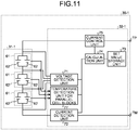
- FIG. 11 is a diagram for explaining a detailed configuration of a secondary battery pack of a sixth embodiment.
- FIG. 11 the same elements as those in FIG. 9 are denoted by the same reference numerals.
- FIG. 11 is different from FIG. 9 in the addition of a temperature detector 77 that is connected to all the parallel cell blocks 61 to detect the temperature of each of the parallel cell blocks 61, instead of the temperature detector 76 that detects the temperature of the storage battery module 31-1.
- FIG. 12 is a process flowchart of an anomaly detection process in the sixth embodiment.
- FIG. 12 the same parts as those in FIG. 10 are denoted by the same reference numerals.
- the measured direct-current internal resistance values R1, R2, and R3 are corrected on the basis of temperature information of the storage battery module 31-1 detected by the temperature detector 76 to determine anomaly from the corrected direct-current internal resistance values.
- the sixth embodiment is different from the fifth embodiment in that the measured direct-current internal resistance values R1, R2, and R3 are corrected on the basis of temperature information of each parallel cell block 61 detected by the temperature detector 76 to determine anomaly from the corrected direct-current internal resistance values.
- the secondary battery pack 30-1 performs the operations from step S11 to step S17 in the first embodiment.
- the calculator 74 calculates, on the basis of a temperature detection signal of the parallel cell block 61 output from the temperature detector 77, a temperature correction for each of the direct-current internal resistance values R1 calculated as in the first embodiment to R3, so as to eliminate the influence of temperature thereon (step S18E).
- the calculator 74 determines whether there is an anomaly in the cells by comparing the ratio RT and a predetermined set value A for cell anomaly detection (step S19E2).
- the set value A is set in the range of 1.2 or more to 2.0 or less.
- step S21 When the ratio RT is greater than the set value A in the determination of step S19E2, that is, when RT > A (No at step S19E2), the calculator 74 determines presence of a non-normal cell (step S21).
- step S19E2 When the ratio RT is equal to or less than the set value A in the determination of step S19E2, that is, when RT ⁇ A (Yes at step S19E2), the calculator 74 determines that there is no non-normal cell and that all the cells are normal (step S20).
- the switch of the current control 75 is opened to stop charging and discharging to and from the secondary battery pack 30-1, or the external device (for example, the BMU 36, the PCS 12, the storage battery controller 5, or the host control device 6) is notified of the anomaly in the secondary battery pack 30-1 via an information communication channel, and the external device stops the charge and discharge operation to the secondary battery pack 30-1.
- the external device for example, the BMU 36, the PCS 12, the storage battery controller 5, or the host control device 6
- the direct-current internal resistance values of the parallel cell blocks 61 can be individually corrected on the basis of the temperature information of each of the parallel cell blocks 61 detected by the temperature detector 77. Consequently, it is possible to more accurately detect the parallel cell block 61 exhibiting a high direct-current internal resistance.
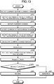
- FIG. 13 is a process flowchart of an anomaly detection process in a seventh embodiment.
- FIG. 13 the same parts as those in FIG. 5 are denoted by the same reference numerals.
- the measured direct-current internal resistance values R1, R2, and R3 are used without change.
- the seventh embodiment is different from the first embodiment in that the measured direct-current internal resistance values R1, R2, and R3 are corrected on the basis of the voltage detected by the voltage detector 71.
- the secondary battery pack 30-1 performs the operations from step S11 to step S17 in the first embodiment.
- the calculator 74 calculates, on the basis of a temperature detection signal of each parallel cell block 61 output from the temperature detector 77, a voltage correction for each of the direct-current internal resistance values R1 to R3 calculated as in the first embodiment so as to eliminate the influence of voltage of each of the parallel cell blocks 61 detected by the voltage detector 71 (step S18F).
- the calculator 74 determines whether there is an anomaly in the cells by comparing between the ratio RT and a predetermined set value A for cell anomaly detection (step S19F2).
- the set value A is typically set in the range of 1.2 or more to 2.0 or less.
- step S21 When the ratio RT is greater than the set value A in the determination of step S19F2, that is, when RT > A (No at step S19F2), the calculator 74 determines presence of a non-normal cell (step S21).
- step S19F2 When the ratio RT is equal to or less then the set value A in the determination of step S19F2, that is, when RT ⁇ A (Yes at step S19F2), the calculator 74 determines that there is no non-normal cell and that all the cells are normal (step S20).
- the switch of the current control 75 is opened to stop charging and discharging to and from the secondary battery pack 30-1, or the external device (for example, the BMU 36, the PCS 12, the storage battery controller 5, or the host control device 6) is notified of the anomaly in the secondary battery pack 30-1 via an information communication channel, and the external device stops the charge and discharge operation to the secondary battery pack 30-1.
- the external device for example, the BMU 36, the PCS 12, the storage battery controller 5, or the host control device 6
- the direct-current internal resistance values of the parallel cell blocks 61 can be individually accurately corrected in accordance with the voltage detected by the voltage detector 71. Consequently, it is possible to more accurately detect the parallel cell block 61 exhibiting a high direct-current internal resistance.
- FIG. 14 is a process flowchart of an anomaly detection process in an eighth embodiment.
- FIG. 14 the same parts as those in FIG. 5 are denoted by the same reference numerals.
- the measured direct-current internal resistance values R1, R2, and R3 are used without change.
- the eighth embodiment is different from the first embodiment in that the direct-current internal resistances are corrected in accordance with the remaining amount of the batteries (state of charge (SOC)) of the storage battery module 31-1.
- the current detector 72 detects the charge and discharge currents of the storage battery module 31-1, and thus the SOC can be calculated by integrating the charge and discharge currents.
- the direct-current internal resistance value varies depending on a difference in the SOC.
- the current detector 72 detects the charge and discharge currents of the storage battery module 31-1 and the charge and discharge currents of the parallel cell blocks 61.
- the calculator 74 calculates the SOC of each of the parallel cell blocks 61 by integrating the detected charge and discharge currents.
- the calculator 74 thus corrects the direct-current internal resistances using the calculated SOC.
- the secondary battery pack 30-1 performs the operations from step S11 to step S17 in the first embodiment.
- the calculator 74 calculates the SOC by integrating the charge and discharge currents of the storage battery module 31-1 output from the current detector 72, and individually corrects the direct-current internal resistance values R1 to R3 calculated on the basis of the calculated SOC (step S18G).
- the calculator 74 determines whether there is an anomaly in the cells by comparing the ratio RT and a predetermined set value A for cell anomaly detection (step S19G2).
- the set value A is typically set in the range of 1.2 or more to 2.0 or less.
- step S21 When the ratio RT is greater than the set value A in the determination of step S19G2, that is, when RT > A (No at step S19G2), the calculator 74 determines presence of a non-normal cell (step S21).
- step S19G2 When the ratio RT is equal to or less than the set value A in the determination of step S19G2, that is, when RT ⁇ A (Yes at step S19G2), the calculator 74 determines that there is no non-normal cell and that all the cells are normal (step S20).
- the switch of the current control 75 is opened to stop charging and discharging to and from the secondary battery pack 30-1, or the external device (for example, the BMU 36, the PCS 12, the storage battery controller 5, or the host control device 6) is notified of the anomaly in the secondary battery pack 30-1 via an information communication channel, and the external device stops the charge and discharge operation to the secondary battery pack 30-1.
- the external device for example, the BMU 36, the PCS 12, the storage battery controller 5, or the host control device 6
- the SOC is found from the current information obtained by the current detector 72 to accurately correct the direct-current internal resistance value of each of the parallel cell blocks 61.
- accurate detection of the parallel cell block 61 exhibiting a high direct-current internal resistance is feasible.
- FIG. 15 is a process flowchart of an anomaly detection process in a ninth embodiment.
- FIG. 15 the same parts as those in FIG. 5 are denoted by the same reference numerals.
- the measured direct-current internal resistance values R1, R2, and R3 are used without change.
- the ninth embodiment is different from the first embodiment in that the direct-current internal resistances are corrected in accordance with current values of the charge and discharge currents.
- batteries may show hysteresis characteristics in the voltage curve called open circuit voltage (OCV) and closed circuit voltage (CCV), and as a result, they may excessively vary in voltage.
- OCV open circuit voltage
- CCV closed circuit voltage
- the current detector 72 detects the charge and discharge currents of the storage battery module 31-1 and the charge and discharge currents of the parallel cell blocks 61, and the calculator calculates a correction for the variation in the direct-current internal resistance value of each of the parallel cell blocks 61 on the basis of the detected current values.
- the secondary battery pack 30-1 performs the operations from step S11 to step S17 in the first embodiment.
- the calculator 74 then corrects each of the direct-current internal resistance values R1 to R3 calculated on the basis of the charge and discharge currents of the storage battery module 31-1 output from the current detector 72 (step S18H).
- the calculator 74 determines whether there is an anomaly in the cells by comparing the ratio RT and a predetermined set value A for cell anomaly detection (step S19H2) .
- the set value A is typically set in the range of 1.2 or more to 2.0 or less.
- step S21 When the ratio RT is greater than the set value A in the determination of step S19H2, that is, when RT > A (No at step S19H2), the calculator 74 determines presence of a non-normal cell (step S21).
- step S19H2 When the ratio RT is equal to or less than the set value A in the determination of step S19H2, that is, when RT ⁇ A (Yes at step S19H2), the calculator 74 determines that there is no non-normal cell and that all the cells are normal (step S20).
- the switch of the current control 75 is opened to stop charging and discharging to and from the secondary battery pack 30-1, or the external device (for example, the BMU 36, the PCS 12, the storage battery controller 5, or the host control device 6) is notified of the anomaly in the secondary battery pack 30-1 via an information communication channel, and the external device stops the charge and discharge operation to the secondary battery pack 30-1.
- the external device for example, the BMU 36, the PCS 12, the storage battery controller 5, or the host control device 6
- the direct-current internal resistance values of the parallel cell blocks 61 are accurately corrected in accordance with the current values detected by the current detector 72 to accurately detect the parallel cell block 61 exhibiting a high direct-current internal resistance.
- the set value A is constant.
- the set value A may be variable with secular change in the system taken into account, or may be changed according to the operation procedure.
Landscapes
- Engineering & Computer Science (AREA)
- Electrochemistry (AREA)
- Manufacturing & Machinery (AREA)
- Chemical & Material Sciences (AREA)
- Chemical Kinetics & Catalysis (AREA)
- General Chemical & Material Sciences (AREA)
- General Physics & Mathematics (AREA)
- Physics & Mathematics (AREA)
- Power Engineering (AREA)
- Microelectronics & Electronic Packaging (AREA)
- Charge And Discharge Circuits For Batteries Or The Like (AREA)
- Secondary Cells (AREA)
- Battery Mounting, Suspending (AREA)
- Connection Of Batteries Or Terminals (AREA)
- Supply And Distribution Of Alternating Current (AREA)
Abstract
Description
- An embodiment herein relates generally to a battery monitoring device and a method.
- In recent years, the use of safe and clean natural energy including solar power generation and wind power generation has been growing. However, the output of natural energy is unstable, so that a large scale of introduction of natural energy may adversely affect the voltage or frequency of the power grid. If the supply of natural energy greatly exceeds power demand, natural-energy power generation systems need to be stopped, lowering the use rate of power generation facilities.
- Conventionally, to stabilize the voltage and frequency of the power grid, a governor-free control and a load frequency control (LFC) function of generators, and load leveling by pumped-storage power generation have been implemented. However, issues arise such as an insufficient lower margin of generators, restrictions on construction site of a pumped storage power plant, and a long construction period.
- In view of this, stationary large-scale storage battery systems including secondary batteries and relatively less restricted by the conditions of site are increasingly attracting attention.
- Such a large-scale storage battery system is known, including a battery pack which incorporates secondary battery blocks in which parallel cell blocks of parallel-connected battery cells are connected in series.
-
- Patent Literature 1: Japanese Patent No.
4606846 - Patent Literature 2: Japanese Patent Application Laid-open No.
2014-075317 - Patent Literature 3: Japanese Patent Application Laid-open No.
2014-119397 - Patent Literature 4: Japanese Patent Application Laid-open No.
2014-023362 - Patent Literature 5: Japanese Patent Application Laid-open No.
2014-041747 - Patent Literature 6: Japanese Patent Application Laid-open No.
2014-110198 - Patent Literature 7: Japanese Patent Application Laid-open No.
2015-008040 - Patent Literature 8: Japanese Patent Application Laid-open No.
2013-137867 - Patent Literature 9: Japanese Patent Application Laid-open No.
2014-127404 - For adopting the above configuration, it is necessary to detect anomaly in any of the cells of the parallel cell blocks. To solve this, anomaly determination is proposed, which includes calculating a ratio of the maximum value to the minimum value of the direct-current internal resistance of each of the parallel cell blocks, and determining anomaly in the battery cell when the ratio exceeds a predetermined set value. However, in such a method, a battery cell with an extremely low internal resistance value (battery cell with excellent performance) may be determined as non-normal.
- In view of the above, an object of the present invention is to provide a battery monitoring device and method which can accurately detect anomaly in any of battery cells of a parallel cell block caused by various factors such as coming-off of a battery cell or degradation of cells.
- A battery monitoring device according to an embodiment monitors a state of a secondary battery block including a plurality of parallel cell blocks connected in series, the parallel cell blocks each including a plurality of battery cells connected in parallel.
- A current detector of a battery monitoring device detects current flowing through each of the parallel cell blocks.
- A voltage detector detects voltage of each of the parallel cell blocks when the current flowing through the parallel cell block is a first current value, and when the current flowing through the parallel cell block is a second current value.
- A calculator that calculates a direct-current internal resistance value of each of the parallel cell blocks on the basis of a differential current between the first current value and the second current value, the voltage of the parallel cell block at the first current value, and the voltage of the parallel cell block at the second current value.
- A determiner that performs anomaly determination for the parallel cell blocks on the basis of internal resistance values of the parallel cell blocks and a maximum value of the direct-current internal resistance values of the parallel cell blocks.
-
-
FIG. 1 is a schematic configuration diagram of a natural-energy power generation system including a storage battery system according to an embodiment.-
FIG. 2 is a schematic configuration block diagram of the storage battery system according to the embodiment. -
FIG. 3 is a diagram for explaining a detailed configuration of a secondary battery pack. -
FIG. 4 is a diagram for explaining a detailed configuration of a BMU. -
FIG. 5 is a process flowchart of an anomaly detection process in a first embodiment. -
FIG. 6 is a process flowchart of an anomaly detection process in a second embodiment. -
FIG. 7 is a process flowchart of an anomaly detection process in a third embodiment. -
FIG. 8 is a process flowchart of an anomaly detection process in a fourth embodiment. -
FIG. 9 is a diagram for explaining a detailed configuration of a secondary battery pack of a fifth embodiment. -
FIG. 10 is a process flowchart of an anomaly detection process in the fifth embodiment. -
FIG. 11 is a diagram for explaining a detailed configuration of a secondary battery pack of a sixth embodiment. -
FIG. 12 is a process flowchart of an anomaly detection process in the sixth embodiment. -
FIG. 13 is a process flowchart of an anomaly detection process in a seventh embodiment. -
FIG. 14 is a process flowchart of an anomaly detection process in an eighth embodiment. -
FIG. 15 is a process flowchart of an anomaly detection process in a ninth embodiment.
-
- Hereinafter, embodiments will be described in detail with reference to the accompanying drawings.
-
FIG. 1 is a schematic configuration diagram of a natural-energy power generation system including a storage battery system according to an embodiment. - A natural-energy
power generation system 100 functions as a power system and includes a natural-energy power generation unit 1, apower meter 2, astorage battery system 3, atransformer 4, astorage battery controller 5, and ahost control device 6. The natural-energy power generation unit 1 can output system power, using natural energy such as solar light, hydraulic-power, wind power, biomass, and geothermal energy (renewable power). Thepower meter 2 measures the power generated by the natural-energy power generation unit 1. Thestorage battery system 3 is charged with surplus electric power of the natural-energy power generation unit 1 on the basis of the measurement result of thepower meter 2, and discharges power to make up for underpower and superimposes the power on the power generated by the natural-energy power generation unit 1 for output. Thetransformer 4 converts the voltage of the output power from the natural-energy power generation unit 1 (including power on which the output power from thestorage battery system 3 is superimposed). Thestorage battery controller 5 locally controls thestorage battery system 3. Thehost control device 6 remotely controls thestorage battery controller 5. -
FIG. 2 is a schematic configuration block diagram of the storage battery system according to the embodiment. Thestorage battery system 3 includes astorage battery device 11 that stores therein electric power, and a power conditioning system (PCS) 12 that converts direct-current power supplied from thestorage battery device 11 into alternating-current power having a desired power quality and supplies the alternating-current power to a load. - The
storage battery device 11 includes a plurality of battery board units 21-1 to 21-N (N being a natural number), and abattery terminal board 22 connected to the battery board units 21-1 to 21-N. - The battery board units 21-1 to 21-N include a plurality of battery boards 23-1 to 23-M (M being a natural number) that are connected to each other in parallel, a
gateway device 24, and a direct-currentpower supply device 25 that supplies direct-current power to a battery management unit (BMU) and cell monitoring units (CMUs) for operation, which will be described below. - A configuration of the battery boards will now be described.
- Each of the battery boards 23-1 to 23-M is connected to output power supply lines (buses) LHO and LLO via a high-potential power supply line LH and a low-potential power supply line LL, and supplies electric power to the PCS 12 being a main circuit.
- The battery boards 23-1 to 23-M have the same configuration, therefore, the battery board 23-1 is explained as an example.
- The battery board 23-1 includes a plurality (24 in
FIG. 2 ) of secondary battery packs 30-1 to 30-24, aservice disconnect 33 provided between the secondary battery pack 30-12 and the secondary battery pack 30-13, acurrent sensor 34, and acontactor 35. The secondary battery packs 30-1 to 30-24, theservice disconnect 33, thecurrent sensor 34, and thecontactor 35 are connected in series. - In the configuration described above, the secondary battery packs 30-1 to 30-24 each include a storage battery module and a CMU. The whole secondary battery packs 30-1 to 30-24 include a plurality of storage battery modules 31-1 to 31-24, and a plurality (24 in
FIG. 2 ) of CMUs 32-1 to 32-24 included in the storage battery modules 31-1 to 31-24, respectively. - The storage battery modules 31-1 to 31-24 form a battery pack in which battery cells are connected in series and in parallel. The storage battery modules 31-1 to 31-24 connected in series form a battery pack group.
- The battery board 23-1 also includes a
BMU 36 connected to the communication line of each of the CMUs 32-1 to 32-24 and the output line of thecurrent sensor 34. - Under the control of the
gateway device 24, theBMU 36 controls the entire battery board 23-1, and opens and closes thecontactor 35 on the basis of a result of the communication (voltage data and temperature data, which will be described below) with each of the CMUs 32-1 to 32-24 and a result of the detection of thecurrent sensor 34. - Next, a configuration of the
battery terminal board 22 will be described. - The
battery terminal board 22 includes a plurality of board breakers 41-1 to 41-N corresponding to the battery board units 21-1 to 21-N, and a master device 42 being a microcomputer for controlling the entirestorage battery device 11. - The master device 42 and the
PCS 12 are connected via a controlpower supply line 51 through which power is supplied to themaster device 12 via an uninterruptible power system (UPS) 12A of thePCS 12 and acontrol communication line 52 being Ethernet (registered trademark) for transfer of control data. - A detailed configuration of the secondary battery packs 30-1 to 30-24 will now be described.
-
FIG. 3 is a diagram for explaining a detailed configuration of a secondary battery pack. - The secondary battery packs 30-1 to 30-24 have the same configuration, therefore, the secondary battery pack 30-1 is explained as an example below.
- The storage battery module 31-1 of the secondary battery pack 30-1 includes a plurality (three in
FIG. 3 ) ofparallel cell blocks 61 that are connected in series, and each of the parallel cell blocks 61 includes a plurality (two inFIG. 3 ) ofbattery cells 62 that are connected to each other in parallel. - The CMU 32-1 of the secondary battery pack 30-1 includes a voltage detector 71, a current detector 72, a set-
value storage 73, acalculator 74, and acurrent control 75. The voltage detector 71 detects voltage of each of the parallel cell blocks 61. The current detector 72 detects conduction current of the storage battery module 31-1 with a shunt resistor or a hall current transformer (CT), for example. The set-value storage 73 stores in advance various types of set-value data such as set-value data for anomaly determination (reference direct-current internal resistance ratio) on the storage battery module 31-1. Thecalculator 74 receives output signals from the voltage detector 71 and the current detector 72, calculates the direct-current internal resistance of each of theparallel cell blocks 61, and determines an non-normal battery cell by comparing a ratio of the calculated direct-current internal resistances of theparallel cell blocks 61 and a value of the set-value data in the set-value storage 73. Thecurrent control 75 includes a mechanical switch or a semiconductor switch, and shuts off a charge and discharge circuit to stop charging and discharging to and from the storage battery module 31-1 when thecalculator 74 determines an anomaly in the battery cells. - In the configuration described above, the electric power of the storage battery module 31-1 is connected to an external device such as a charge and discharge device, a load, or a charger, via a positive electrode terminal TP and a negative electrode terminal TM.
-
FIG. 4 is a diagram for explaining a detailed configuration of a BMU. - The
BMU 36 is configured to be able to communicate with the secondary battery packs 30-1 to 30-24 via a communication line CL (seeFIG. 2 ). TheBMU 36 includes an MPU 81 that controls theentire BMU 36, a communication controller 82 that conforms to the control area network (CAN) standard to perform CAN communication with the CMUs 32-1 to 32-24, and amemory 83 that stores voltage data and temperature data transmitted from the CMUs 32-1 to 32-24. - The
storage battery controller 5 detects electric power generated by the natural-energy power generation unit 1, and controls thestorage battery device 11 to reduce variation in the output of the generated electric power, to relieve influence of the generated electric power on the power grid. Thestorage battery controller 5 or thehost control device 6 calculates a decrease amount of the variation for thestorage battery device 11, and provides it to the PCS (Power Conditioning System) 12 corresponding to thestorage battery device 11 as a charge and discharge command. - As described above, the board breakers 41-1 to 41-N correspond to the battery boards 23-1 to 23-M.
- The board breakers 41-1 to 41-M are sequentially turned on (closed) upon startup of the
storage battery system 3. Thereby, thestorage battery system 3 is connected to the main circuit, allowing the storage battery to be charged or discharged. -
FIG. 5 is a process flowchart of an anomaly detection process in a first embodiment. - In the following, an anomaly detection operation by the CMU 32-1 will be described by way of example.
- In this case, the voltage detector 71 of the CMU 32-1 detects voltage at predetermined timing (voltage detection timing), and outputs detected voltage data to the
calculator 74. - Similarly, the current detector 72 of the CMU 32-1 detects current at predetermined timing (current detection timing), and outputs detected current data to the
calculator 74. - Consequently, the
calculator 74 constantly monitors variation or non-variation in the current. Thecalculator 74 detects current with no predetermined variation (before variation in the current) at certain timing (current detection timing), and stores the detected current as detected current data with no variation in the detected current (step S11). - In this case, the current value before current variation detected by the current detector 72 only needs to be continuously substantially constant, therefore, the current need not be limited to current in a non-conduction state. For example, a stationary large-capacity storage battery continuously charges and discharges without stop for the purpose of frequency or voltage adjustment, however, the current thereof can be used as the current before the current variation. Thus, the external device to be connected via the positive electrode terminal TP and the negative electrode terminal TM may be a charge and discharge device, a charger, or a load. In other words, there is no particular limitation to the external device as long as the environment that the conduction current of the storage battery module 31-1 varies is created.
- Next, the
calculator 74 detects voltage (in the example ofFIG. 3 , detected voltages V1 to V3 corresponding to the three parallel cell blocks 61) of each of theparallel cell blocks 61 with no current variation (before current variation) at predetermined timing (voltage detection timing), from the output of the voltage detector 71, and stores the detected voltage as detected voltage data with no current variation (the detected voltages V1 to V3 in the above example)(step S12). - The
calculator 74 then detects a variation in the current in the storage battery module 31-1 from the output from the current detector 72 (step S13). - Upon detecting the current variation, the
calculator 74 detects the varied current (after the current variation) at predetermined timing (current detection timing), and stores the detected current as detected current data after the current variation (step S14). - Next, the
calculator 74 detects the varied voltage (in the example ofFIG. 3 , detected voltages V1' to V3' corresponding to the three the parallel cell blocks 61) of each of theparallel cell blocks 61 after the current variation at predetermined timing (voltage detection timing), from the output of the voltage detector 71. Thecalculator 74 then stores the detected voltage (detected voltages V1' to V3' in the above example) as detected voltage data after the current variation (step S15). - In this example, in principle the voltage detection timing and the current detection timing coincides with each other. However, the voltage detection timing and the current detection timing may shift from each other as long as the current is stable and does not vary after the current variation.
- The
calculator 74 then calculates a current variation amount ΔI by subtracting a current value corresponding to the detected current data before the current variation from a current value corresponding to the detected current data after the current variation (step S16) . - The
calculator 74 then finds differences in voltage (= V1' - V1, V2' - V21, V3' - V3) among the parallel cell blocks by subtracting the voltages V1 to V3 of theparallel cell blocks 61 corresponding to the detected voltage data before the current variation acquired at step S12 from the voltages V1' to V3' of theparallel cell blocks 61 corresponding to the detected voltage data after the current variation acquired at step S15, respectively. Thecalculator 74 then calculates a direct-current internal resistance value of each of theparallel cell blocks 61 by dividing the voltage difference by the current variation amount ΔI calculated by the current variation-amount calculation (step S16)(step S17). - More specifically, a direct-current internal resistance R1 of the first
parallel cell block 61 is represented by the following formula:
- Similarly, a direct-current internal resistance R2 of the second
parallel cell block 61 and a direct-current internal resistance R3 of the thirdparallel cell block 61 are represented by the following formulae:

- The
calculator 74 then calculates a ratio RT of the maximum value Rmax (= numerator) to the average value (= denominator) of the acquired direct-current internal resistances R1 to R3 (step S18). - More specifically, the
calculator 74 first specifies the maximum direct-current internal resistance Rmax from the direct-current internal resistances R1 to R3 of theparallel cell blocks 61 calculated at step S17. - The
calculator 74 then calculates the average value of the direct-current internal resistances = (R1 + R2 + R3)/3. - The
calculator 74 then calculates the ratio RT of the maximum direct-current internal resistance Rmax to the average value of the direct-current internal resistances by the following formula:
- The
calculator 74 then compares the ratio RT and a predetermined set value A for cell anomaly detection to determine whether there is a non-normal cell (step S19). - The set value A is typically set in the range of 1.2 or more to 2.0 or less.
- When the ratio RT is greater than the set value A in the determination of step S19, that is, when
RT > A (Yes at step S19),
thecalculator 74 determines that there is a non-normal cell (step S21). - When the ratio RT is equal to or less then the set value A in the determination of step S19, that is, when
RT ≤ A (No at step S19),
thecalculator 74 determines that there is no non-normal cell and all the cells are normal (step S20). - As a result of the determination, when no non-normal cell is found and all the cells are normal, the charge and discharge operation continues.
- On the other hand, when a non-normal cell is found as a result of the determination, the switch of the
current control 75 is opened to stop charging and discharging to and from the secondary battery pack 30-1, or the external device (for example, theBMU 36, thePCS 12, thestorage battery controller 5, or the host control device 6) is notified of the anomaly in the secondary battery pack 30-1 via an information communication channel, and the external device stops the charge and discharge operation to the secondary battery pack 30-1. - As described above, according to the first embodiment, the CMU 32-1 determines an anomaly in the
parallel cell block 61 from the ratio RT of the maximum direct-current internal resistance Rmax to the average value of the direct-current internal resistances (R1 + R2 + R3)/3. Consequently, with presence of a battery cell with an extremely low direct-current internal resistance (battery cell with excellent performance), the CMU 32-1 can reduce the influence of the battery by averaging and accurately detect theparallel cell block 61 exhibiting a high direct-current internal resistance. - In the above, the anomaly detection of the parallel cell blocks 61 is described. Alternatively, it is possible to calculate the direct-current internal resistance of the storage battery module 31-1 to determine a storage battery module with a high ratio as non-normal by a similar method.
-
FIG. 6 is a process flowchart of an anomaly detection process in a second embodiment. - In
FIG. 6 , the same parts as those inFIG. 5 are denote by the same reference numerals. - In the first embodiment, anomaly in the
parallel cell block 61 is determined from the ratio RT of the maximum direct-current internal resistance Rmax to the average value (R1 + R2 + R3)/3 of the direct-current internal resistances. The second embodiment is different from the first embodiment in that anomaly in theparallel cell block 61 is determined from a ratio RT1 that is calculated on the basis of the maximum direct-current internal resistance value Rmax and the average value of the direct-current internal resistance values excluding the direct-current internal resistance value corresponding to the maximum direct-current internal resistance value Rmax among the direct-current internal resistance values R1 to R3, instead of the ratio RT of the first embodiment. - Hereinafter, different points will be mainly described.
- First, the secondary battery pack 30-1 performs the operations from step S11 to step S17 as in the first embodiment.
- The
calculator 74 then calculates the ratio RT1 between the maximum value Rmax (= numerator) of the acquired direct-current internal resistance values R1 to R3 and the average value of the direct-current internal resistance values excluding the direct-current internal resistance value corresponding to the maximum direct-current internal resistance value Rmax among the direct-current internal resistance values R1 to R3 (step S18A). - More specifically, the
calculator 74 first specifies the maximum direct-current internal resistance Rmax from the direct-current internal resistances R1 to R3 of theparallel cell blocks 61 calculated at step S17. - The
calculator 74 then calculates a value by subtracting the maximum value Rmax from the sum of the direct-current internal resistances = (R1 + R2 + R3), that is
- More specifically, when the direct-current internal resistance R2 = Rmax,

- The value resulting from (R1 + R2 + R3) - Rmax is the sum of the direct-current internal resistance values excluding the maximum direct-current internal resistance value Rmax.
- Thus, in this case, the average value of the direct-current internal resistance values excluding the maximum direct-current internal resistance value Rmax can be found by dividing the value obtained by subtracting the maximum value Rmax from the sum of the direct-current internal resistances = (R1 + R2 + R3) by two. When the number of the direct-current internal resistance values calculated in this manner is m, the average value of the direct-current internal resistance values excluding the maximum direct-current internal resistance value Rmax can be found by dividing, by (m - 1), the value found by subtracting the maximum direct-current internal resistance value Rmax from the sum of the direct-current internal resistances.
- The
calculator 74 then calculates the ratio RT1 of the maximum direct-current internal resistance Rmax to the average value of the direct-current internal resistance values excluding the maximum value Rmax by the following formula:
- When the number of the direct-current internal resistance values calculated as above is m, the ratio RT1 of the maximum direct-current internal resistance Rmax to the average value of the direct-current internal resistance values excluding the maximum direct-current internal resistance value Rmax is calculated by the following formula:

- The
calculator 74 then determines whether there is an anomaly in the cells by comparing the ratio RT1 and a certain set value A for cell anomaly detection (step S19A). - The set value A is typically set in the range of 1.2 or more to 2.0 or less.
- When the ratio RT1 is greater than the set value A in the determination of step S19A, that is, when
RT1 > A (No at step S19A),
thecalculator 74 determines presence of a non-normal cell (step S21). - When the ratio RT1 is equal to or less than the set value A in the determination of step S19A, that is, when
RT1 ≤ A (Yes at step S19A),
thecalculator 74 determines that there is no non-normal cell and all the cells are normal (step S20). - As a result of the determination, when no non-normal cell is found and all the cells are normal, the charge and discharge operation continues.
- On the other hand, when a non-normal cell is found as a result of the determination, the switch of the
current control 75 is opened to stop charging and discharging to and from the secondary battery pack 30-1, or the external device (for example, theBMU 36, thePCS 12, thestorage battery controller 5, or the host control device 6) is notified of the anomaly in the secondary battery pack 30-1 via an information communication channel, and the external device stops the charge and discharge operation to the secondary battery pack 30-1. - As described above, according to the second embodiment, a difference between the maximum direct-current internal resistance value Rmax and the average value of the direct-current internal resistance values excluding the direct current direct-current internal resistance value corresponding the maximum direct-current internal resistance value Rmax among the direct-current internal resistance values R1 to R3 and the maximum direct-current internal resistance value Rmax is further increased, which can further ensure detection of the
parallel cell block 61 having a high direct-current internal resistance. -
FIG. 7 is a process flowchart of an anomaly detection process in a third embodiment. - In
FIG. 7 , the same parts as those inFIG. 5 are denoted by the same reference numerals. - In the first embodiment, an anomaly in the
parallel cell block 61 is determined from the ratio RT of the maximum direct-current internal resistance Rmax to the average value of the direct-current internal resistance (R1 + R2 + R3)/3. The third embodiment is different from the first embodiment in that an anomaly in theparallel cell block 61 is determined from a ratio RT2 that is calculated on the basis of the maximum direct-current internal resistance value Rmax and a value found by dividing the average value of the direct-current internal resistance values by a standard deviation σ of the direct-current internal resistance values, instead of the ratio RT of the first embodiment. - In this example, the ratio RT2 is used for determining whether the maximum direct-current internal resistance Rmax is an outlier (a value greatly deviated from the other values) relative to the rest of the direct-current internal resistance values.
- Hereinafter, different points will be mainly described.
- First, the secondary battery pack 30-1 performs the operations from step S11 to step S17 in the first embodiment.
- The
calculator 74 then calculates a standard deviation of the direct-current internal resistance values (step S18B). - More specifically, the
calculator 74 finds the average value of the direct-current internal resistances R1 to R3 (R1 + R2 + R3)/3 calculated at step S17, and calculates the standard deviation σ by the following formula.
- The
calculator 74 then calculates the ratio RT2 of the difference Rmax - (R1 + R2 + R3)/3 between the maximum direct-current internal resistance Rmax and the average value relative to the calculated standard deviation σ.
- The
calculator 74 then determines whether there is an anomaly in the cells by comparing the ratio RT2 and a certain set value A for cell anomaly detection (step S19B). - The set value A is typically set in the range of 1.2 or more to 2.0 or less.
- When the ratio RT2 is greater than the set value A in the determination of step S19B, that is, when
RT2 > A (No at step S19B),
thecalculator 74 determines presence of an non-normal cell (step S21). - When the ratio RT2 is equal to or less than the set value A in the determination of step S19B, that is, when
RT2 ≤ A (Yes at step S19B),
thecalculator 74 determines that there is no non-normal cell and all the cells are normal (step S20). - As a result of the determination, when no non-normal cell is found and all the cells are normal, the charge and discharge operation continues.
- On the other hand, when a non-normal cell is found as a result of the determination, the switch of the
current control 75 is opened to stop charging and discharging to and from the secondary battery pack 30-1, or the external device (for example, theBMU 36, thePCS 12, thestorage battery controller 5, or the host control device 6) is notified of the anomaly in the secondary battery pack 30-1 via an information communication channel, and the external device stops the charge and discharge operation to the secondary battery pack 30-1. - As described above, according to the third embodiment, it is possible to detect the
parallel cell block 61 having a high direct-current internal resistance as an non-normal deviation value of the standard deviation σ that corresponds to the distribution of the direct-current internal resistance. -
FIG. 8 is a process flowchart of an anomaly detection process in a fourth embodiment. - In
FIG. 8 , the same parts as those inFIG. 5 are denoted by the same reference numerals. - In the first embodiment, an anomaly in the
parallel cell block 61 is determined from the ratio RT of the maximum direct-current internal resistance Rmax to the average value of the direct-current internal resistances (R1 + R2 + R3)/3. The fourth embodiment is different from the first embodiment in that an anomaly in theparallel cell block 61 is determined from a ratio RT3 that is calculated on the basis of a value found by dividing the difference between the maximum value Rmax and the average value of the direct-current internal resistance values by a standard deviation σ' of the direct-current internal resistance values excluding the maximum direct-current internal resistance value Rmax, instead of the ratio RT of the first embodiment. - Hereinafter, different points will be mainly described.
- First, the secondary battery pack 30-1 performs the operations from step S11 to step S17 in the first embodiment.
- The
calculator 74 then calculates a standard deviation of the direct-current internal resistance values (step S18C). - More specifically, at step S17, the
calculator 74 finds the average value of the direct-current internal resistance values excluding the maximum direct-current internal resistance value from the calculated sum of the direct-current internal resistances R1 to R3 (R1 + R2 + R3 - Rmax)/2, and calculates the standard deviation σ' by the following formula.
- The
calculator 74 then calculates the ratio RT3 of the difference Rmax - (R1 + R2 + R3)/3 between the maximum direct-current internal resistance Rmax and the average value relative to the calculated standard deviation σ'.
- The
calculator 74 then determines whether there is an anomaly in the cells by comparing the ratio RT3 and a predetermined set value A for cell anomaly detection (step S19C). - The set value A is typically set in the range of 1.2 or more to 2.0 or less.
- When the ratio RT3 is greater than the set value A in the determination of step S19C, that is, when
RT3 > A (No at step S19C),
thecalculator 74 determines presence of a non-normal cell (step S21). - When the ratio RT3 is equal to or less than the set value A in the determination of step S19C, that is, when
RT3 ≤ A (Yes at step S19C),
thecalculator 74 determines that there is no non-normal cell and that all the cells are normal (step S20). - As a result of the determination, when no non-normal cell is found and all the cells are normal, the charge and discharge operation continues.
- On the other hand, when a non-normal cell is found as a result of the determination, the switch of the
current control 75 is opened to stop charging and discharging to and from the secondary battery pack 30-1, or the external device (for example, theBMU 36, thePCS 12, thestorage battery controller 5, or the host control device 6) is notified of the anomaly in the secondary battery pack 30-1 via an information communication channel, and the external device stops the charge and discharge operation to the secondary battery pack 30-1. - As described above, according to the fourth embodiment, it is possible to accurately detect the
parallel cell block 61 having a high direct-current internal resistance as a non-normal deviation value of the standard deviation σ' that corresponds to the distribution of the direct-current internal resistances, with the influence of the maximum direct-current internal resistance removed. -
FIG. 9 is a diagram for explaining a detailed configuration of a secondary battery pack of a fifth embodiment. - In
FIG. 9 , the same elements as those inFIG. 3 are denoted by the same reference numerals. -
FIG. 9 is different fromFIG. 3 in the addition of atemperature detector 76 that detects the temperature of the storage battery module 31-1. - The
temperature detector 76 may be a single temperature sensor (temperature detector) connected to the storage battery module 31-1 to measure the ambient temperature of the storage battery module 31-1, a plurality of temperature sensors placed inside the storage battery module 31-1 considering the temperature distribution in the storage battery module 31-1, a temperature sensor provided in one of thebattery cells 62 rising highest in temperature in the storage battery module 31-1 on the premise that the storage battery module 31-1 uniformly rises in temperature, or a temperature sensor used upon estimation of a temperature increase in thebattery cells 62 according to temperature distribution. -
FIG. 10 is a process flowchart of an anomaly detection process in the fifth embodiment. - In
FIG. 10 , the same parts as those inFIG. 5 denote the same reference numerals. - In the first embodiment, the measured direct-current internal resistance values R1, R2, and R3 are used without change. The fifth embodiment is different from the first embodiment in that the measured direct-current internal resistance values R1, R2, and R3 are corrected on the basis of temperature information of the storage battery module 31-1 detected by the
temperature detector 76 and determines anomaly on the basis of the corrected direct-current internal resistance values. - Hereinafter, different points will be mainly described.
- First, the secondary battery pack 30-1 performs the operations from step S11 to step S17 in the first embodiment.
- The
calculator 74 then calculates, on the basis of a temperature detection signal of the storage battery module 31-1 output from thetemperature detector 76, a temperature correction for the direct-current internal resistance values R1 to R3 calculated as in the first embodiment so as to eliminate the influence of temperature (step S18D). - The temperature-correction calculation will now be described in detail.
- Typically, the higher the battery temperature is, the lower the direct-current internal resistance is, and the lower the battery temperature is, the higher the direct-current internal resistance is.
- In the fifth embodiment, thus, when the temperature detected by the temperature detector 76 (for example, 30°C higher than the reference temperature by 10°C) is higher than a predetermined reference temperature (for example, 20°C), the internal resistance values R1 to R3 are corrected to smaller values at a predetermined ratio (for example, 1%), or a database containing converted values of the internal resistance values relative to temperatures is pre-stored to correct the measured internal resistance values R1 to R3 referring to the database.
- The
calculator 74 then calculates the ratio RT of the maximum direct-current internal resistance Rmax to the average value of the corrected direct-current internal resistances by the following formula (step S19D1):
- The
calculator 74 then determines whether there is an anomaly in the cells by comparing the ratio RT and a predetermined set value A for cell anomaly detection (step S19D2). - The set value A is set in the range of 1.2 or more to 2.0 or less.
- When the ratio RT is greater than the set value A in the determination of step S19D2, that is, when
RT > A (No at step S19D2),
thecalculator 74 determines presence of a non-normal cell (step S21). - When the ratio RT is equal to or less than the set value A in the determination of step S19D2, that is, when
RT ≤ A (Yes at step S19D2),
thecalculator 74 determines that there is no non-normal cell and that all the cells are normal (step S20). - As a result of the determination, when no non-normal cell is found and that all the cells are normal, the charge and discharge operation continues.
- On the other hand, when a non-normal cell is found, the switch of the
current control 75 is opened to stop charging and discharging to and from the secondary battery pack 30-1, or the external device (for example, theBMU 36, thePCS 12, thestorage battery controller 5, or the host control device 6) is notified of the anomaly in the secondary battery pack 30-1 via an information communication channel, and the external device stops the charge and discharge operation to the secondary battery pack 30-1. - As described above, according to the fifth embodiment, the direct-current internal resistance values of the
parallel cell blocks 61 are corrected on the basis of the temperature information of the storage battery module 31-1 from thetemperature detector 76, which makes it possible to more accurately detect theparallel cell block 61 exhibiting a high direct-current internal resistance. -
FIG. 11 is a diagram for explaining a detailed configuration of a secondary battery pack of a sixth embodiment. - In
FIG. 11 , the same elements as those inFIG. 9 are denoted by the same reference numerals. -
FIG. 11 is different fromFIG. 9 in the addition of a temperature detector 77 that is connected to all theparallel cell blocks 61 to detect the temperature of each of theparallel cell blocks 61, instead of thetemperature detector 76 that detects the temperature of the storage battery module 31-1. -
FIG. 12 is a process flowchart of an anomaly detection process in the sixth embodiment. - In
FIG. 12 , the same parts as those inFIG. 10 are denoted by the same reference numerals. - In the fifth embodiment, the measured direct-current internal resistance values R1, R2, and R3 are corrected on the basis of temperature information of the storage battery module 31-1 detected by the
temperature detector 76 to determine anomaly from the corrected direct-current internal resistance values. The sixth embodiment is different from the fifth embodiment in that the measured direct-current internal resistance values R1, R2, and R3 are corrected on the basis of temperature information of eachparallel cell block 61 detected by thetemperature detector 76 to determine anomaly from the corrected direct-current internal resistance values. - Hereinafter, different points will be mainly described.
- First, the secondary battery pack 30-1 performs the operations from step S11 to step S17 in the first embodiment.
- The
calculator 74 then calculates, on the basis of a temperature detection signal of theparallel cell block 61 output from the temperature detector 77, a temperature correction for each of the direct-current internal resistance values R1 calculated as in the first embodiment to R3, so as to eliminate the influence of temperature thereon (step S18E). - The
calculator 74 then calculates the ratio RT of the maximum direct-current internal resistance Rmax to the average value of the corrected direct-current internal resistances (step S19E1).
- The
calculator 74 then determines whether there is an anomaly in the cells by comparing the ratio RT and a predetermined set value A for cell anomaly detection (step S19E2). - The set value A is set in the range of 1.2 or more to 2.0 or less.
- When the ratio RT is greater than the set value A in the determination of step S19E2, that is, when
RT > A (No at step S19E2),
thecalculator 74 determines presence of a non-normal cell (step S21). - When the ratio RT is equal to or less than the set value A in the determination of step S19E2, that is, when
RT ≤ A (Yes at step S19E2),
thecalculator 74 determines that there is no non-normal cell and that all the cells are normal (step S20). - As a result of the determination, when no non-normal cell is found and all the cells are normal, the charge and discharge operation continues.
- On the other hand, when a non-normal cell is found as a result of the determination, the switch of the
current control 75 is opened to stop charging and discharging to and from the secondary battery pack 30-1, or the external device (for example, theBMU 36, thePCS 12, thestorage battery controller 5, or the host control device 6) is notified of the anomaly in the secondary battery pack 30-1 via an information communication channel, and the external device stops the charge and discharge operation to the secondary battery pack 30-1. - As described above, according to the sixth embodiment, the direct-current internal resistance values of the
parallel cell blocks 61 can be individually corrected on the basis of the temperature information of each of theparallel cell blocks 61 detected by the temperature detector 77. Consequently, it is possible to more accurately detect theparallel cell block 61 exhibiting a high direct-current internal resistance. -
FIG. 13 is a process flowchart of an anomaly detection process in a seventh embodiment. - In
FIG. 13 , the same parts as those inFIG. 5 are denoted by the same reference numerals. - In the first embodiment, the measured direct-current internal resistance values R1, R2, and R3 are used without change. The seventh embodiment is different from the first embodiment in that the measured direct-current internal resistance values R1, R2, and R3 are corrected on the basis of the voltage detected by the voltage detector 71.
- Hereinafter, different points will be mainly described.
- First, the secondary battery pack 30-1 performs the operations from step S11 to step S17 in the first embodiment.
- The
calculator 74 then calculates, on the basis of a temperature detection signal of eachparallel cell block 61 output from the temperature detector 77, a voltage correction for each of the direct-current internal resistance values R1 to R3 calculated as in the first embodiment so as to eliminate the influence of voltage of each of theparallel cell blocks 61 detected by the voltage detector 71 (step S18F). - The
calculator 74 then calculates the ratio RT of the maximum direct-current internal resistance Rmax to the average value of the corrected direct-current internal resistances (step S19F1).
- The
calculator 74 then determines whether there is an anomaly in the cells by comparing between the ratio RT and a predetermined set value A for cell anomaly detection (step S19F2). - The set value A is typically set in the range of 1.2 or more to 2.0 or less.
- When the ratio RT is greater than the set value A in the determination of step S19F2, that is, when
RT > A (No at step S19F2),
thecalculator 74 determines presence of a non-normal cell (step S21). - When the ratio RT is equal to or less then the set value A in the determination of step S19F2, that is, when
RT ≤ A (Yes at step S19F2),
thecalculator 74 determines that there is no non-normal cell and that all the cells are normal (step S20). - As a result of the determination, when no non-normal cell is found and all the cells are normal, the charge and discharge operation continues.
- On the other hand, when a non-normal cell is found as a result of the determination, the switch of the
current control 75 is opened to stop charging and discharging to and from the secondary battery pack 30-1, or the external device (for example, theBMU 36, thePCS 12, thestorage battery controller 5, or the host control device 6) is notified of the anomaly in the secondary battery pack 30-1 via an information communication channel, and the external device stops the charge and discharge operation to the secondary battery pack 30-1. - As described above, according to the seventh embodiment, the direct-current internal resistance values of the
parallel cell blocks 61 can be individually accurately corrected in accordance with the voltage detected by the voltage detector 71. Consequently, it is possible to more accurately detect theparallel cell block 61 exhibiting a high direct-current internal resistance. Eighth Embodiment -
FIG. 14 is a process flowchart of an anomaly detection process in an eighth embodiment. - In
FIG. 14 , the same parts as those inFIG. 5 are denoted by the same reference numerals. - In the first embodiment, the measured direct-current internal resistance values R1, R2, and R3 are used without change. The eighth embodiment is different from the first embodiment in that the direct-current internal resistances are corrected in accordance with the remaining amount of the batteries (state of charge (SOC)) of the storage battery module 31-1.
- First, the SOC will be described.
- The current detector 72 detects the charge and discharge currents of the storage battery module 31-1, and thus the SOC can be calculated by integrating the charge and discharge currents.
- Meanwhile, the direct-current internal resistance value varies depending on a difference in the SOC. Thus, the current detector 72 detects the charge and discharge currents of the storage battery module 31-1 and the charge and discharge currents of the parallel cell blocks 61. The
calculator 74 calculates the SOC of each of theparallel cell blocks 61 by integrating the detected charge and discharge currents. - The
calculator 74 thus corrects the direct-current internal resistances using the calculated SOC. - Hereinafter, different points will be mainly described.
- First, the secondary battery pack 30-1 performs the operations from step S11 to step S17 in the first embodiment.
- The
calculator 74 then calculates the SOC by integrating the charge and discharge currents of the storage battery module 31-1 output from the current detector 72, and individually corrects the direct-current internal resistance values R1 to R3 calculated on the basis of the calculated SOC (step S18G). - The
calculator 74 then calculates the ratio RT of the maximum direct-current internal resistance Rmax to the average value of the corrected direct-current internal resistance by the following formula (step S19G1):
- The
calculator 74 then determines whether there is an anomaly in the cells by comparing the ratio RT and a predetermined set value A for cell anomaly detection (step S19G2). - The set value A is typically set in the range of 1.2 or more to 2.0 or less.
- When the ratio RT is greater than the set value A in the determination of step S19G2, that is, when
RT > A (No at step S19G2),
thecalculator 74 determines presence of a non-normal cell (step S21). - When the ratio RT is equal to or less than the set value A in the determination of step S19G2, that is, when
RT ≤ A (Yes at step S19G2),
thecalculator 74 determines that there is no non-normal cell and that all the cells are normal (step S20). - As a result of the determination, when no non-normal cell is found and all the cells are normal, the charge and discharge operation continues.
- On the other hand, a non-normal cell is found as a result of the determination, the switch of the
current control 75 is opened to stop charging and discharging to and from the secondary battery pack 30-1, or the external device (for example, theBMU 36, thePCS 12, thestorage battery controller 5, or the host control device 6) is notified of the anomaly in the secondary battery pack 30-1 via an information communication channel, and the external device stops the charge and discharge operation to the secondary battery pack 30-1. - As described above, according to the eighth embodiment, the SOC is found from the current information obtained by the current detector 72 to accurately correct the direct-current internal resistance value of each of the parallel cell blocks 61. Thereby, accurate detection of the
parallel cell block 61 exhibiting a high direct-current internal resistance is feasible. -
FIG. 15 is a process flowchart of an anomaly detection process in a ninth embodiment. - In
FIG. 15 , the same parts as those inFIG. 5 are denoted by the same reference numerals. - In the first embodiment, the measured direct-current internal resistance values R1, R2, and R3 are used without change. The ninth embodiment is different from the first embodiment in that the direct-current internal resistances are corrected in accordance with current values of the charge and discharge currents.
- Along with a change in the charge and discharge currents from charge to discharge or from discharge to charge, batteries may show hysteresis characteristics in the voltage curve called open circuit voltage (OCV) and closed circuit voltage (CCV), and as a result, they may excessively vary in voltage.
- Thus, in the ninth embodiment, the current detector 72 detects the charge and discharge currents of the storage battery module 31-1 and the charge and discharge currents of the
parallel cell blocks 61, and the calculator calculates a correction for the variation in the direct-current internal resistance value of each of the parallel cell blocks 61 on the basis of the detected current values. - Hereinafter, different points will be mainly described.
- First, the secondary battery pack 30-1 performs the operations from step S11 to step S17 in the first embodiment.
- The
calculator 74 then corrects each of the direct-current internal resistance values R1 to R3 calculated on the basis of the charge and discharge currents of the storage battery module 31-1 output from the current detector 72 (step S18H). - The
calculator 74 then calculates the ratio RT of the maximum direct-current internal resistance Rmax to the average value of the corrected direct-current internal resistances (step S19H1).
- The
calculator 74 then determines whether there is an anomaly in the cells by comparing the ratio RT and a predetermined set value A for cell anomaly detection (step S19H2) . - The set value A is typically set in the range of 1.2 or more to 2.0 or less.
- When the ratio RT is greater than the set value A in the determination of step S19H2, that is, when
RT > A (No at step S19H2),
thecalculator 74 determines presence of a non-normal cell (step S21). - When the ratio RT is equal to or less than the set value A in the determination of step S19H2, that is, when
RT ≤ A (Yes at step S19H2),
thecalculator 74 determines that there is no non-normal cell and that all the cells are normal (step S20). - As a result of the determination, when no non-normal cell is found and all the cells are normal, the charge and discharge operation continues.
- On the other hand, when a non-normal cell is found as a result of the determination, the switch of the
current control 75 is opened to stop charging and discharging to and from the secondary battery pack 30-1, or the external device (for example, theBMU 36, thePCS 12, thestorage battery controller 5, or the host control device 6) is notified of the anomaly in the secondary battery pack 30-1 via an information communication channel, and the external device stops the charge and discharge operation to the secondary battery pack 30-1. - According to the ninth embodiment described above, the direct-current internal resistance values of the
parallel cell blocks 61 are accurately corrected in accordance with the current values detected by the current detector 72 to accurately detect theparallel cell block 61 exhibiting a high direct-current internal resistance. - While some embodiments of the invention have been described, these embodiments are merely examples, and are not intended to limit the scope of the invention. These novel embodiments may be implemented in various other forms, and various omissions, replacements, and modifications may be made without departing from the scope and spirit of the invention. These embodiments and the modifications are included in the scope and spirit of the invention, and are included in the invention described in the claims and their equivalents.
- For example, in the above description the set value A is constant. However, the set value A may be variable with secular change in the system taken into account, or may be changed according to the operation procedure.
Claims (10)
- A battery monitoring device that monitors a state of a secondary battery block including a plurality of parallel cell blocks connected in series, the parallel cell blocks each including a plurality of battery cells connected in parallel, the battery monitoring device, comprising:a current detector that detects current flowing through each of the parallel cell blocks;a voltage detector that detects voltage of each of the parallel cell blocks when the current flowing through the parallel cell block is a first current value, and when the current flowing through the parallel cell block is a second current value;a calculator that calculates a direct-current internal resistance value of each of the parallel cell blocks on the basis of a differential current between the first current value and the second current value, the voltage of the parallel cell block at the first current value, and the voltage of the parallel cell block at the second current value; anda determiner that performs anomaly determination for the parallel cell blocks on the basis of internal resistance values of the parallel cell blocks and a maximum value of the direct-current internal resistance values of the parallel cell blocks.
- The battery monitoring device according to claim 1, wherein the determiner calculates a ratio of the maximum value to an average value of direct-current internal resistances of each of the parallel cell blocks and determines that the parallel cell block is non-normal when the ratio exceeds a preset value.
- The battery monitoring device according to claim 1, wherein
the calculator calculates an average value of all of the direct-current internal resistance values excluding the maximum value, and
the determiner calculates a ratio of the maximum value to the average value of all the direct-current internal resistance values excluding the maximum value, and determines that there is an anomaly in the parallel cell block when the ratio exceeds a preset value. - The battery monitoring device according to claim 1, wherein
the calculator calculates a standard deviation σ of all of the direct-current internal resistance values, and
the determiner determines, based on the standard deviation σ, that there is an anomaly in the parallel cell block when the maximum value is an outlier relative to the rest of the direct-current internal resistance values. - The battery monitoring device according to claim 1, wherein
the calculator calculates a standard deviation σ' of all of the direct-current internal resistance values excluding the maximum value, and
the determiner determines, based on the standard deviation σ', that there is an anomaly in the parallel cell block, when the maximum value is an outlier relative to the rest of the direct-current internal resistance values excluding the maximum value. - The battery monitoring device according to claim 1, wherein
the calculator corrects the internal resistance values of the parallel cell blocks according to a value of the voltage detected by the voltage detector, and
the determiner performs anomaly determination for the parallel cell block according to the corrected internal resistance values. - The battery monitoring device according to claim 1, wherein
the calculator calculates state of charge of the parallel cell blocks by integrating the current flowing through the parallel cell blocks detected by the current detector, and corrects the internal resistance values of the parallel cell blocks according to the calculated SOC, and
the determiner performs anomaly determination for the parallel cell blocks from the corrected internal resistance values. - The battery monitoring device according to claim 1, wherein
the calculator corrects the internal resistance values of the parallel cell blocks according to the current flowing through the parallel cell blocks detected by the current detector, and
the determiner performs an anomaly determination for the parallel cell blocks according to the corrected internal resistance values. - The battery monitoring device according to claim 1, further comprising:a temperature detector that detects temperature of each of the parallel cell blocks, whereinthe calculator corrects the internal resistance values of the parallel cell blocks according to the temperatures detected by the temperature detector, andthe determiner performs anomaly determination for the parallel cell blocks according to the corrected internal resistance values.
- A method to be executed by a battery monitoring device that monitors a state of a secondary battery block comprising a plurality of parallel cell blocks connected in series, the parallel cell blocks each including a plurality of battery cells connected in parallel, the method comprising:detecting current flowing through each of the parallel cell blocks;detecting voltage of each of the parallel cell blocks when the current of a first current value flows through the parallel cell blocks and when the current of a second current value flows through the parallel cell blocks;calculating internal resistance values of the parallel cell blocks on the basis of a differential current between the first current value and the second current value, the voltage of the parallel cell blocks at the first current value, and the voltage of the parallel cell blocks at the second current value; and performing anomaly determination for the parallel cell blocks according to the internal resistance values of the parallel cell blocks and a maximum value of the internal resistance values of the parallel cell blocks.
Applications Claiming Priority (1)
| Application Number | Priority Date | Filing Date | Title |
|---|---|---|---|
| PCT/JP2016/057198 WO2017154112A1 (en) | 2016-03-08 | 2016-03-08 | Battery monitoring device and method |
Publications (3)
| Publication Number | Publication Date |
|---|---|
| EP3429053A1 true EP3429053A1 (en) | 2019-01-16 |
| EP3429053A4 EP3429053A4 (en) | 2019-11-06 |
| EP3429053B1 EP3429053B1 (en) | 2024-10-02 |
Family
ID=59790374
Family Applications (1)
| Application Number | Title | Priority Date | Filing Date |
|---|---|---|---|
| EP16893444.6A Active EP3429053B1 (en) | 2016-03-08 | 2016-03-08 | Battery monitoring device and method |
Country Status (5)
| Country | Link |
|---|---|
| US (1) | US11693060B2 (en) |
| EP (1) | EP3429053B1 (en) |
| JP (1) | JP6571268B2 (en) |
| KR (1) | KR102113054B1 (en) |
| WO (1) | WO2017154112A1 (en) |
Cited By (4)
| Publication number | Priority date | Publication date | Assignee | Title |
|---|---|---|---|---|
| EP3940404A4 (en) * | 2019-07-22 | 2022-04-20 | LG Energy Solution, Ltd. | DEVICE AND METHOD FOR DIAGNOSING BATTERY RESISTANCE |
| EP4286869A4 (en) * | 2021-10-28 | 2024-10-02 | LG Energy Solution, Ltd. | BATTERY DIAGNOSTIC METHOD AND BATTERY SYSTEM ADOPTING SAME |
| EP4318008A4 (en) * | 2021-11-02 | 2024-10-23 | Lg Energy Solution, Ltd. | Battery diagnosis method based on degree of resistance degradation and battery system to which battery diagnosis method is applied |
| EP4506704A1 (en) * | 2023-08-08 | 2025-02-12 | Samsung SDI Co., Ltd. | Method and apparatus for diagnosing battery system |
Families Citing this family (36)
| Publication number | Priority date | Publication date | Assignee | Title |
|---|---|---|---|---|
| JP6419977B2 (en) * | 2015-09-03 | 2018-11-14 | 株式会社東芝 | Voltage fluctuation suppressing apparatus and method |
| JP6846659B2 (en) * | 2016-09-13 | 2021-03-24 | パナソニックIpマネジメント株式会社 | Management device and power storage system |
| JP2018048893A (en) * | 2016-09-21 | 2018-03-29 | Ntn株式会社 | Secondary battery degradation determination device |
| JP7006359B2 (en) * | 2018-02-21 | 2022-01-24 | トヨタ自動車株式会社 | Battery smoke determination method and battery system |
| JP7056363B2 (en) * | 2018-05-10 | 2022-04-19 | トヨタ自動車株式会社 | Battery system |
| CN110635177B (en) * | 2018-06-22 | 2021-05-11 | 华为技术有限公司 | Battery control method, battery control device, and computer-readable storage medium |
| DE102018210883A1 (en) * | 2018-07-03 | 2020-01-09 | Robert Bosch Gmbh | Diagnostic method for a plurality of electrochemical energy stores that can be connected in parallel |
| JP7309717B2 (en) * | 2018-08-03 | 2023-07-18 | 株式会社半導体エネルギー研究所 | Secondary battery anomaly detection system |
| JP7120062B2 (en) * | 2019-02-07 | 2022-08-17 | トヨタ自動車株式会社 | BATTERY CHARGE/DISCHARGE CONTROL DEVICE AND BATTERY CHARGE/DISCHARGE CONTROL METHOD |
| KR102794167B1 (en) * | 2019-03-06 | 2025-04-11 | 주식회사 엘지에너지솔루션 | Apparatus and method for detecting undervoltage battery cell |
| KR102824995B1 (en) * | 2019-04-19 | 2025-06-24 | 주식회사 엘지에너지솔루션 | Apparatus and method for managing battery using nondestructive resistance analysis |
| KR102832250B1 (en) * | 2019-06-24 | 2025-07-08 | 삼성에스디아이 주식회사 | Method of detecting abnormal battery cell |
| KR102679707B1 (en) * | 2019-07-10 | 2024-06-27 | 주식회사 엘지에너지솔루션 | Apparatus and method for diagnosing cooling requirement for battery module |
| KR102742036B1 (en) * | 2019-10-01 | 2024-12-13 | 주식회사 엘지에너지솔루션 | Appratus and method for calculating battery power |
| JP7191873B2 (en) * | 2020-01-17 | 2022-12-19 | 株式会社東芝 | Charge/discharge control device, charge/discharge system, charge/discharge control method, and charge/discharge control program |
| CN111257774B (en) * | 2020-01-21 | 2022-10-21 | 福建时代星云科技有限公司 | Method and system for detecting direct current impedance of electric automobile |
| JP7314855B2 (en) * | 2020-04-21 | 2023-07-26 | トヨタ自動車株式会社 | BATTERY STATE DETERMINATION DEVICE AND STATE DETERMINATION METHOD |
| KR20220013112A (en) | 2020-07-24 | 2022-02-04 | 노일호 | Dried Laver And Method For Manufacturing The Same |
| KR102794109B1 (en) * | 2020-09-03 | 2025-04-09 | 주식회사 엘지에너지솔루션 | Apparatus and method for managing battery |
| JP7326237B2 (en) * | 2020-09-07 | 2023-08-15 | 株式会社東芝 | Determination device, power storage system, determination method, and determination program for multiple batteries |
| CN112433157B (en) * | 2020-10-29 | 2024-03-01 | 云南电网有限责任公司丽江供电局 | Online monitoring and differentiation system for internal short circuit and leakage faults of power lithium batteries |
| KR102630222B1 (en) * | 2020-11-05 | 2024-01-25 | 주식회사 엘지에너지솔루션 | Apparatus and method for diagnosing battery |
| DE102021205161B4 (en) * | 2021-05-20 | 2024-01-18 | Volkswagen Aktiengesellschaft | Method and control device for determining a maximum current limit of a battery system with at least two batteries |
| CN113533985B (en) * | 2021-06-28 | 2024-05-03 | 合肥国轩高科动力能源有限公司 | Identification method of battery pack internal resistance abnormal module and storage medium thereof |
| KR102920622B1 (en) * | 2021-11-04 | 2026-01-29 | 주식회사 엘지에너지솔루션 | Method for managing battery banks and battery system using the same |
| US20230142500A1 (en) * | 2021-11-10 | 2023-05-11 | Enersys Delaware Inc. | Battery modules with anti-arcing, hot swapping, and/or self-disabling features |
| CN114325435B (en) * | 2021-12-22 | 2023-07-14 | 蜂巢能源科技股份有限公司 | Method, device and battery system for detecting failed batteries |
| CN114325436B (en) * | 2021-12-24 | 2023-10-10 | 华鼎国联四川动力电池有限公司 | Calibration method of DCIR test value |
| CN114660466A (en) * | 2022-03-25 | 2022-06-24 | 华能澜沧江水电股份有限公司 | Storage battery fault prediction method and system |
| KR102833784B1 (en) * | 2022-05-10 | 2025-07-11 | 주식회사 엘지에너지솔루션 | Internal resistance evaluation device and battery system |
| KR102954865B1 (en) * | 2022-05-20 | 2026-04-17 | 주식회사 엘지에너지솔루션 | Battery diagnosis method, battery diagnosis apparatus and battery system providing the same |
| KR20230162255A (en) * | 2022-05-20 | 2023-11-28 | 주식회사 엘지에너지솔루션 | Battery diagnosis method, battery diagnosis apparatus and battery system providing the same |
| US20240157812A1 (en) * | 2022-11-16 | 2024-05-16 | Transportation Ip Holdings, Llc | Energy storage management system |
| CN116106747A (en) * | 2023-01-28 | 2023-05-12 | 奇瑞新能源汽车股份有限公司 | Method and device for detecting false welding of power battery module busbar |
| JP2025001230A (en) * | 2023-06-20 | 2025-01-08 | トヨタ自動車株式会社 | Power supply system |
| KR20260046684A (en) * | 2024-09-30 | 2026-04-07 | 주식회사 엘지에너지솔루션 | Method for determining normal resistsnce range, and diagnostic device and batery system using the same |
Family Cites Families (17)
| Publication number | Priority date | Publication date | Assignee | Title |
|---|---|---|---|---|
| JPS466846Y1 (en) | 1967-06-26 | 1971-03-10 | ||
| JP3750318B2 (en) * | 1997-11-14 | 2006-03-01 | 日産自動車株式会社 | Module charger / discharger |
| JP3505111B2 (en) | 1998-10-07 | 2004-03-08 | 日本碍子株式会社 | Operation method of sodium-sulfur battery |
| JP2004031123A (en) | 2002-06-26 | 2004-01-29 | Nissan Motor Co Ltd | Method and apparatus for calculating capacity of assembled batteries connected in parallel |
| JP4606846B2 (en) * | 2004-11-12 | 2011-01-05 | パナソニック株式会社 | Battery monitoring device |
| JP5092218B2 (en) | 2005-09-06 | 2012-12-05 | 富士通株式会社 | Abnormality detection method for battery pack, battery pack and electronic device |
| JP4690223B2 (en) * | 2006-02-24 | 2011-06-01 | 株式会社デンソー | Battery state quantity calculation device |
| JP6056344B2 (en) * | 2011-12-12 | 2017-01-11 | 日産自動車株式会社 | Battery connection control device |
| JP5973723B2 (en) | 2011-12-27 | 2016-08-23 | 株式会社東芝 | Secondary battery device and manufacturing method thereof |
| JP2014023362A (en) | 2012-07-20 | 2014-02-03 | Toshiba Corp | Control device, controlled device, control method, and control program |
| JP6289803B2 (en) | 2012-08-22 | 2018-03-07 | 株式会社東芝 | Storage battery device, storage battery device management method, and storage battery system |
| JP2014075317A (en) | 2012-10-05 | 2014-04-24 | Sumitomo Bakelite Co Ltd | Conductive connection sheet, semiconductor device and electronic apparatus |
| JP2014110198A (en) | 2012-12-04 | 2014-06-12 | Toshiba Corp | Battery pack device, battery pack device inspection method and inspection program |
| JP6253137B2 (en) | 2012-12-18 | 2017-12-27 | 株式会社東芝 | Battery state estimation device for secondary battery |
| JP2014127404A (en) | 2012-12-27 | 2014-07-07 | Furukawa Electric Co Ltd:The | Method for replacing battery pack |
| JP2015008040A (en) | 2013-06-24 | 2015-01-15 | 株式会社東芝 | Secondary battery device and module connection discrimination method |
| CN104614630B (en) * | 2015-01-19 | 2017-11-28 | 清华大学 | A kind of recognition methods of battery micro-short circuit |
-
2016
- 2016-03-08 WO PCT/JP2016/057198 patent/WO2017154112A1/en not_active Ceased
- 2016-03-08 KR KR1020187028340A patent/KR102113054B1/en active Active
- 2016-03-08 US US16/082,792 patent/US11693060B2/en active Active
- 2016-03-08 JP JP2018503897A patent/JP6571268B2/en active Active
- 2016-03-08 EP EP16893444.6A patent/EP3429053B1/en active Active
Cited By (6)
| Publication number | Priority date | Publication date | Assignee | Title |
|---|---|---|---|---|
| EP3940404A4 (en) * | 2019-07-22 | 2022-04-20 | LG Energy Solution, Ltd. | DEVICE AND METHOD FOR DIAGNOSING BATTERY RESISTANCE |
| US11846680B2 (en) | 2019-07-22 | 2023-12-19 | Lg Energy Solution, Ltd. | Battery resistance diagnosis device and method |
| EP4286869A4 (en) * | 2021-10-28 | 2024-10-02 | LG Energy Solution, Ltd. | BATTERY DIAGNOSTIC METHOD AND BATTERY SYSTEM ADOPTING SAME |
| US12345770B2 (en) | 2021-10-28 | 2025-07-01 | Lg Energy Solution, Ltd. | Battery diagnosis method and battery system applying the same |
| EP4318008A4 (en) * | 2021-11-02 | 2024-10-23 | Lg Energy Solution, Ltd. | Battery diagnosis method based on degree of resistance degradation and battery system to which battery diagnosis method is applied |
| EP4506704A1 (en) * | 2023-08-08 | 2025-02-12 | Samsung SDI Co., Ltd. | Method and apparatus for diagnosing battery system |
Also Published As
| Publication number | Publication date |
|---|---|
| US11693060B2 (en) | 2023-07-04 |
| US20190081369A1 (en) | 2019-03-14 |
| KR20180122378A (en) | 2018-11-12 |
| WO2017154112A1 (en) | 2017-09-14 |
| EP3429053A4 (en) | 2019-11-06 |
| JPWO2017154112A1 (en) | 2018-12-13 |
| KR102113054B1 (en) | 2020-05-20 |
| JP6571268B2 (en) | 2019-09-04 |
| EP3429053B1 (en) | 2024-10-02 |
Similar Documents
| Publication | Publication Date | Title |
|---|---|---|
| EP3429053B1 (en) | Battery monitoring device and method | |
| US11913998B2 (en) | Management device and power supply system | |
| US9065296B2 (en) | Battery pack, method of measuring voltage of the battery pack, and energy storage system including the battery pack | |
| US8810203B2 (en) | Battery control device and battery control method | |
| US9172259B2 (en) | Apparatus for managing battery, and energy storage system | |
| US11054475B2 (en) | Electric storage capacity estimation apparatus and method for operating the same | |
| US20200176829A1 (en) | Electricity storage system and management device | |
| JP5843051B2 (en) | Pack battery and secondary battery discharge control method | |
| KR101732854B1 (en) | Storage battery device and storage battery system | |
| US8949056B2 (en) | Battery management system and battery pack including battery management system | |
| EP3439132A1 (en) | Power supply system, control system and power control method for power supply system | |
| KR20130063406A (en) | Apparatus for controlling battery pack, and energy storage system including the battery pack | |
| KR101105142B1 (en) | How to measure remaining battery life | |
| CN101335461A (en) | Charging system, electronic device and charging method | |
| TW202327161A (en) | Battery management system and battery management method | |
| EP0505333B1 (en) | Estimating the charge of batteries | |
| US20190036176A1 (en) | Battery charge control algorithm | |
| EP3602724B1 (en) | Controlling a battery charge level | |
| CN105203958A (en) | Battery state monitoring circuit and battery device | |
| EP3323665B1 (en) | A battery pack balancing system and method | |
| JP7240893B2 (en) | battery controller | |
| US11249140B2 (en) | Method and system for testing a rechargeable battery | |
| KR20150005073A (en) | Method and apparatus for estimating SOC in constant current state, battery management system and energy storage system comprising the same | |
| TWI543495B (en) | Battery management method | |
| KR101608212B1 (en) | Uninterruptible power supply with battery management system |
Legal Events
| Date | Code | Title | Description |
|---|---|---|---|
| STAA | Information on the status of an ep patent application or granted ep patent |
Free format text: STATUS: THE INTERNATIONAL PUBLICATION HAS BEEN MADE |
|
| PUAI | Public reference made under article 153(3) epc to a published international application that has entered the european phase |
Free format text: ORIGINAL CODE: 0009012 |
|
| STAA | Information on the status of an ep patent application or granted ep patent |
Free format text: STATUS: REQUEST FOR EXAMINATION WAS MADE |
|
| 17P | Request for examination filed |
Effective date: 20180905 |
|
| AK | Designated contracting states |
Kind code of ref document: A1 Designated state(s): AL AT BE BG CH CY CZ DE DK EE ES FI FR GB GR HR HU IE IS IT LI LT LU LV MC MK MT NL NO PL PT RO RS SE SI SK SM TR |
|
| AX | Request for extension of the european patent |
Extension state: BA ME |
|
| DAV | Request for validation of the european patent (deleted) | ||
| DAX | Request for extension of the european patent (deleted) | ||
| A4 | Supplementary search report drawn up and despatched |
Effective date: 20191008 |
|
| RIC1 | Information provided on ipc code assigned before grant |
Ipc: H01M 10/42 20060101ALI20191001BHEP Ipc: G01R 31/392 20190101ALI20191001BHEP Ipc: H02J 7/00 20060101AFI20191001BHEP Ipc: G01R 31/389 20190101ALI20191001BHEP Ipc: H01M 10/48 20060101ALI20191001BHEP Ipc: H02J 7/02 20160101ALI20191001BHEP |
|
| STAA | Information on the status of an ep patent application or granted ep patent |
Free format text: STATUS: EXAMINATION IS IN PROGRESS |
|
| 17Q | First examination report despatched |
Effective date: 20220920 |
|
| GRAP | Despatch of communication of intention to grant a patent |
Free format text: ORIGINAL CODE: EPIDOSNIGR1 |
|
| STAA | Information on the status of an ep patent application or granted ep patent |
Free format text: STATUS: GRANT OF PATENT IS INTENDED |
|
| INTG | Intention to grant announced |
Effective date: 20240613 |
|
| GRAS | Grant fee paid |
Free format text: ORIGINAL CODE: EPIDOSNIGR3 |
|
| GRAA | (expected) grant |
Free format text: ORIGINAL CODE: 0009210 |
|
| STAA | Information on the status of an ep patent application or granted ep patent |
Free format text: STATUS: THE PATENT HAS BEEN GRANTED |
|
| AK | Designated contracting states |
Kind code of ref document: B1 Designated state(s): AL AT BE BG CH CY CZ DE DK EE ES FI FR GB GR HR HU IE IS IT LI LT LU LV MC MK MT NL NO PL PT RO RS SE SI SK SM TR |
|
| REG | Reference to a national code |
Ref country code: GB Ref legal event code: FG4D |
|
| REG | Reference to a national code |
Ref country code: CH Ref legal event code: EP |
|
| REG | Reference to a national code |
Ref country code: IE Ref legal event code: FG4D |
|
| REG | Reference to a national code |
Ref country code: DE Ref legal event code: R096 Ref document number: 602016089691 Country of ref document: DE |
|
| REG | Reference to a national code |
Ref country code: LT Ref legal event code: MG9D |
|
| REG | Reference to a national code |
Ref country code: NL Ref legal event code: MP Effective date: 20241002 |
|
| REG | Reference to a national code |
Ref country code: AT Ref legal event code: MK05 Ref document number: 1729159 Country of ref document: AT Kind code of ref document: T Effective date: 20241002 |
|
| PG25 | Lapsed in a contracting state [announced via postgrant information from national office to epo] |
Ref country code: NL Free format text: LAPSE BECAUSE OF FAILURE TO SUBMIT A TRANSLATION OF THE DESCRIPTION OR TO PAY THE FEE WITHIN THE PRESCRIBED TIME-LIMIT Effective date: 20241002 |
|
| PG25 | Lapsed in a contracting state [announced via postgrant information from national office to epo] |
Ref country code: NL Free format text: LAPSE BECAUSE OF FAILURE TO SUBMIT A TRANSLATION OF THE DESCRIPTION OR TO PAY THE FEE WITHIN THE PRESCRIBED TIME-LIMIT Effective date: 20241002 |
|
| PG25 | Lapsed in a contracting state [announced via postgrant information from national office to epo] |
Ref country code: IS Free format text: LAPSE BECAUSE OF FAILURE TO SUBMIT A TRANSLATION OF THE DESCRIPTION OR TO PAY THE FEE WITHIN THE PRESCRIBED TIME-LIMIT Effective date: 20250202 Ref country code: HR Free format text: LAPSE BECAUSE OF FAILURE TO SUBMIT A TRANSLATION OF THE DESCRIPTION OR TO PAY THE FEE WITHIN THE PRESCRIBED TIME-LIMIT Effective date: 20241002 Ref country code: PT Free format text: LAPSE BECAUSE OF FAILURE TO SUBMIT A TRANSLATION OF THE DESCRIPTION OR TO PAY THE FEE WITHIN THE PRESCRIBED TIME-LIMIT Effective date: 20250203 |
|
| PG25 | Lapsed in a contracting state [announced via postgrant information from national office to epo] |
Ref country code: FI Free format text: LAPSE BECAUSE OF FAILURE TO SUBMIT A TRANSLATION OF THE DESCRIPTION OR TO PAY THE FEE WITHIN THE PRESCRIBED TIME-LIMIT Effective date: 20241002 |
|
| PG25 | Lapsed in a contracting state [announced via postgrant information from national office to epo] |
Ref country code: BG Free format text: LAPSE BECAUSE OF FAILURE TO SUBMIT A TRANSLATION OF THE DESCRIPTION OR TO PAY THE FEE WITHIN THE PRESCRIBED TIME-LIMIT Effective date: 20241002 |
|
| PG25 | Lapsed in a contracting state [announced via postgrant information from national office to epo] |
Ref country code: ES Free format text: LAPSE BECAUSE OF FAILURE TO SUBMIT A TRANSLATION OF THE DESCRIPTION OR TO PAY THE FEE WITHIN THE PRESCRIBED TIME-LIMIT Effective date: 20241002 |
|
| PG25 | Lapsed in a contracting state [announced via postgrant information from national office to epo] |
Ref country code: NO Free format text: LAPSE BECAUSE OF FAILURE TO SUBMIT A TRANSLATION OF THE DESCRIPTION OR TO PAY THE FEE WITHIN THE PRESCRIBED TIME-LIMIT Effective date: 20250102 |
|
| PG25 | Lapsed in a contracting state [announced via postgrant information from national office to epo] |
Ref country code: LV Free format text: LAPSE BECAUSE OF FAILURE TO SUBMIT A TRANSLATION OF THE DESCRIPTION OR TO PAY THE FEE WITHIN THE PRESCRIBED TIME-LIMIT Effective date: 20241002 Ref country code: AT Free format text: LAPSE BECAUSE OF FAILURE TO SUBMIT A TRANSLATION OF THE DESCRIPTION OR TO PAY THE FEE WITHIN THE PRESCRIBED TIME-LIMIT Effective date: 20241002 Ref country code: GR Free format text: LAPSE BECAUSE OF FAILURE TO SUBMIT A TRANSLATION OF THE DESCRIPTION OR TO PAY THE FEE WITHIN THE PRESCRIBED TIME-LIMIT Effective date: 20250103 |
|
| PG25 | Lapsed in a contracting state [announced via postgrant information from national office to epo] |
Ref country code: PL Free format text: LAPSE BECAUSE OF FAILURE TO SUBMIT A TRANSLATION OF THE DESCRIPTION OR TO PAY THE FEE WITHIN THE PRESCRIBED TIME-LIMIT Effective date: 20241002 Ref country code: CZ Free format text: LAPSE BECAUSE OF FAILURE TO SUBMIT A TRANSLATION OF THE DESCRIPTION OR TO PAY THE FEE WITHIN THE PRESCRIBED TIME-LIMIT Effective date: 20241002 |
|
| PG25 | Lapsed in a contracting state [announced via postgrant information from national office to epo] |
Ref country code: RS Free format text: LAPSE BECAUSE OF FAILURE TO SUBMIT A TRANSLATION OF THE DESCRIPTION OR TO PAY THE FEE WITHIN THE PRESCRIBED TIME-LIMIT Effective date: 20250102 |
|
| PG25 | Lapsed in a contracting state [announced via postgrant information from national office to epo] |
Ref country code: SM Free format text: LAPSE BECAUSE OF FAILURE TO SUBMIT A TRANSLATION OF THE DESCRIPTION OR TO PAY THE FEE WITHIN THE PRESCRIBED TIME-LIMIT Effective date: 20241002 |
|
| REG | Reference to a national code |
Ref country code: DE Ref legal event code: R097 Ref document number: 602016089691 Country of ref document: DE |
|
| PG25 | Lapsed in a contracting state [announced via postgrant information from national office to epo] |
Ref country code: DK Free format text: LAPSE BECAUSE OF FAILURE TO SUBMIT A TRANSLATION OF THE DESCRIPTION OR TO PAY THE FEE WITHIN THE PRESCRIBED TIME-LIMIT Effective date: 20241002 |
|
| PG25 | Lapsed in a contracting state [announced via postgrant information from national office to epo] |
Ref country code: EE Free format text: LAPSE BECAUSE OF FAILURE TO SUBMIT A TRANSLATION OF THE DESCRIPTION OR TO PAY THE FEE WITHIN THE PRESCRIBED TIME-LIMIT Effective date: 20241002 |
|
| PG25 | Lapsed in a contracting state [announced via postgrant information from national office to epo] |
Ref country code: RO Free format text: LAPSE BECAUSE OF FAILURE TO SUBMIT A TRANSLATION OF THE DESCRIPTION OR TO PAY THE FEE WITHIN THE PRESCRIBED TIME-LIMIT Effective date: 20241002 |
|
| PG25 | Lapsed in a contracting state [announced via postgrant information from national office to epo] |
Ref country code: SK Free format text: LAPSE BECAUSE OF FAILURE TO SUBMIT A TRANSLATION OF THE DESCRIPTION OR TO PAY THE FEE WITHIN THE PRESCRIBED TIME-LIMIT Effective date: 20241002 |
|
| PG25 | Lapsed in a contracting state [announced via postgrant information from national office to epo] |
Ref country code: IT Free format text: LAPSE BECAUSE OF FAILURE TO SUBMIT A TRANSLATION OF THE DESCRIPTION OR TO PAY THE FEE WITHIN THE PRESCRIBED TIME-LIMIT Effective date: 20241002 |
|
| PLBE | No opposition filed within time limit |
Free format text: ORIGINAL CODE: 0009261 |
|
| STAA | Information on the status of an ep patent application or granted ep patent |
Free format text: STATUS: NO OPPOSITION FILED WITHIN TIME LIMIT |
|
| PG25 | Lapsed in a contracting state [announced via postgrant information from national office to epo] |
Ref country code: SE Free format text: LAPSE BECAUSE OF FAILURE TO SUBMIT A TRANSLATION OF THE DESCRIPTION OR TO PAY THE FEE WITHIN THE PRESCRIBED TIME-LIMIT Effective date: 20241002 |
|
| 26N | No opposition filed |
Effective date: 20250703 |
|
| PG25 | Lapsed in a contracting state [announced via postgrant information from national office to epo] |
Ref country code: MC Free format text: LAPSE BECAUSE OF FAILURE TO SUBMIT A TRANSLATION OF THE DESCRIPTION OR TO PAY THE FEE WITHIN THE PRESCRIBED TIME-LIMIT Effective date: 20241002 |
|
| REG | Reference to a national code |
Ref country code: CH Ref legal event code: H13 Free format text: ST27 STATUS EVENT CODE: U-0-0-H10-H13 (AS PROVIDED BY THE NATIONAL OFFICE) Effective date: 20251023 |
|
| PG25 | Lapsed in a contracting state [announced via postgrant information from national office to epo] |
Ref country code: LU Free format text: LAPSE BECAUSE OF NON-PAYMENT OF DUE FEES Effective date: 20250308 |
|
| REG | Reference to a national code |
Ref country code: BE Ref legal event code: MM Effective date: 20250331 |
|
| PGFP | Annual fee paid to national office [announced via postgrant information from national office to epo] |
Ref country code: FR Payment date: 20251231 Year of fee payment: 11 |
|
| PG25 | Lapsed in a contracting state [announced via postgrant information from national office to epo] |
Ref country code: BE Free format text: LAPSE BECAUSE OF NON-PAYMENT OF DUE FEES Effective date: 20250331 |
|
| PG25 | Lapsed in a contracting state [announced via postgrant information from national office to epo] |
Ref country code: CH Free format text: LAPSE BECAUSE OF NON-PAYMENT OF DUE FEES Effective date: 20250331 |
|
| PG25 | Lapsed in a contracting state [announced via postgrant information from national office to epo] |
Ref country code: IE Free format text: LAPSE BECAUSE OF NON-PAYMENT OF DUE FEES Effective date: 20250308 |
|
| PGFP | Annual fee paid to national office [announced via postgrant information from national office to epo] |
Ref country code: GB Payment date: 20260106 Year of fee payment: 11 |
|
| PGFP | Annual fee paid to national office [announced via postgrant information from national office to epo] |
Ref country code: DE Payment date: 20260102 Year of fee payment: 11 |