EP3429031A1 - Poke-in connector - Google Patents
Poke-in connector Download PDFInfo
- Publication number
- EP3429031A1 EP3429031A1 EP18182307.1A EP18182307A EP3429031A1 EP 3429031 A1 EP3429031 A1 EP 3429031A1 EP 18182307 A EP18182307 A EP 18182307A EP 3429031 A1 EP3429031 A1 EP 3429031A1
- Authority
- EP
- European Patent Office
- Prior art keywords
- plate
- wire
- connector
- bending
- support plate
- Prior art date
- Legal status (The legal status is an assumption and is not a legal conclusion. Google has not performed a legal analysis and makes no representation as to the accuracy of the status listed.)
- Withdrawn
Links
- 238000005452 bending Methods 0.000 claims abstract description 58
- 238000003780 insertion Methods 0.000 claims abstract description 43
- 230000037431 insertion Effects 0.000 claims abstract description 43
- 239000000758 substrate Substances 0.000 claims abstract description 35
- 230000008878 coupling Effects 0.000 claims description 10
- 238000010168 coupling process Methods 0.000 claims description 10
- 238000005859 coupling reaction Methods 0.000 claims description 10
- 230000000903 blocking effect Effects 0.000 claims description 7
- 238000000465 moulding Methods 0.000 abstract description 10
- 238000005476 soldering Methods 0.000 description 4
- 230000002708 enhancing effect Effects 0.000 description 2
- 230000014509 gene expression Effects 0.000 description 2
- 238000000034 method Methods 0.000 description 2
- 230000000149 penetrating effect Effects 0.000 description 2
- 230000000694 effects Effects 0.000 description 1
- 230000005489 elastic deformation Effects 0.000 description 1
- 238000009413 insulation Methods 0.000 description 1
- 230000002452 interceptive effect Effects 0.000 description 1
- 239000002184 metal Substances 0.000 description 1
- 238000007789 sealing Methods 0.000 description 1
Images


Classifications
-
- H—ELECTRICITY
- H01—ELECTRIC ELEMENTS
- H01R—ELECTRICALLY-CONDUCTIVE CONNECTIONS; STRUCTURAL ASSOCIATIONS OF A PLURALITY OF MUTUALLY-INSULATED ELECTRICAL CONNECTING ELEMENTS; COUPLING DEVICES; CURRENT COLLECTORS
- H01R4/00—Electrically-conductive connections between two or more conductive members in direct contact, i.e. touching one another; Means for effecting or maintaining such contact; Electrically-conductive connections having two or more spaced connecting locations for conductors and using contact members penetrating insulation
- H01R4/28—Clamped connections, spring connections
- H01R4/48—Clamped connections, spring connections utilising a spring, clip, or other resilient member
- H01R4/4809—Clamped connections, spring connections utilising a spring, clip, or other resilient member using a leaf spring to bias the conductor toward the busbar
- H01R4/48185—Clamped connections, spring connections utilising a spring, clip, or other resilient member using a leaf spring to bias the conductor toward the busbar adapted for axial insertion of a wire end
-
- H—ELECTRICITY
- H01—ELECTRIC ELEMENTS
- H01R—ELECTRICALLY-CONDUCTIVE CONNECTIONS; STRUCTURAL ASSOCIATIONS OF A PLURALITY OF MUTUALLY-INSULATED ELECTRICAL CONNECTING ELEMENTS; COUPLING DEVICES; CURRENT COLLECTORS
- H01R4/00—Electrically-conductive connections between two or more conductive members in direct contact, i.e. touching one another; Means for effecting or maintaining such contact; Electrically-conductive connections having two or more spaced connecting locations for conductors and using contact members penetrating insulation
- H01R4/28—Clamped connections, spring connections
- H01R4/48—Clamped connections, spring connections utilising a spring, clip, or other resilient member
-
- H—ELECTRICITY
- H01—ELECTRIC ELEMENTS
- H01R—ELECTRICALLY-CONDUCTIVE CONNECTIONS; STRUCTURAL ASSOCIATIONS OF A PLURALITY OF MUTUALLY-INSULATED ELECTRICAL CONNECTING ELEMENTS; COUPLING DEVICES; CURRENT COLLECTORS
- H01R13/00—Details of coupling devices of the kinds covered by groups H01R12/70 or H01R24/00 - H01R33/00
- H01R13/40—Securing contact members in or to a base or case; Insulating of contact members
- H01R13/42—Securing in a demountable manner
- H01R13/428—Securing in a demountable manner by resilient locking means on the contact members; by locking means on resilient contact members
-
- H—ELECTRICITY
- H01—ELECTRIC ELEMENTS
- H01R—ELECTRICALLY-CONDUCTIVE CONNECTIONS; STRUCTURAL ASSOCIATIONS OF A PLURALITY OF MUTUALLY-INSULATED ELECTRICAL CONNECTING ELEMENTS; COUPLING DEVICES; CURRENT COLLECTORS
- H01R12/00—Structural associations of a plurality of mutually-insulated electrical connecting elements, specially adapted for printed circuits, e.g. printed circuit boards [PCB], flat or ribbon cables, or like generally planar structures, e.g. terminal strips, terminal blocks; Coupling devices specially adapted for printed circuits, flat or ribbon cables, or like generally planar structures; Terminals specially adapted for contact with, or insertion into, printed circuits, flat or ribbon cables, or like generally planar structures
- H01R12/50—Fixed connections
- H01R12/51—Fixed connections for rigid printed circuits or like structures
- H01R12/53—Fixed connections for rigid printed circuits or like structures connecting to cables except for flat or ribbon cables
-
- H—ELECTRICITY
- H01—ELECTRIC ELEMENTS
- H01R—ELECTRICALLY-CONDUCTIVE CONNECTIONS; STRUCTURAL ASSOCIATIONS OF A PLURALITY OF MUTUALLY-INSULATED ELECTRICAL CONNECTING ELEMENTS; COUPLING DEVICES; CURRENT COLLECTORS
- H01R12/00—Structural associations of a plurality of mutually-insulated electrical connecting elements, specially adapted for printed circuits, e.g. printed circuit boards [PCB], flat or ribbon cables, or like generally planar structures, e.g. terminal strips, terminal blocks; Coupling devices specially adapted for printed circuits, flat or ribbon cables, or like generally planar structures; Terminals specially adapted for contact with, or insertion into, printed circuits, flat or ribbon cables, or like generally planar structures
- H01R12/50—Fixed connections
- H01R12/51—Fixed connections for rigid printed circuits or like structures
- H01R12/515—Terminal blocks providing connections to wires or cables
-
- H—ELECTRICITY
- H01—ELECTRIC ELEMENTS
- H01R—ELECTRICALLY-CONDUCTIVE CONNECTIONS; STRUCTURAL ASSOCIATIONS OF A PLURALITY OF MUTUALLY-INSULATED ELECTRICAL CONNECTING ELEMENTS; COUPLING DEVICES; CURRENT COLLECTORS
- H01R12/00—Structural associations of a plurality of mutually-insulated electrical connecting elements, specially adapted for printed circuits, e.g. printed circuit boards [PCB], flat or ribbon cables, or like generally planar structures, e.g. terminal strips, terminal blocks; Coupling devices specially adapted for printed circuits, flat or ribbon cables, or like generally planar structures; Terminals specially adapted for contact with, or insertion into, printed circuits, flat or ribbon cables, or like generally planar structures
- H01R12/50—Fixed connections
- H01R12/51—Fixed connections for rigid printed circuits or like structures
- H01R12/55—Fixed connections for rigid printed circuits or like structures characterised by the terminals
- H01R12/57—Fixed connections for rigid printed circuits or like structures characterised by the terminals surface mounting terminals
-
- H—ELECTRICITY
- H01—ELECTRIC ELEMENTS
- H01R—ELECTRICALLY-CONDUCTIVE CONNECTIONS; STRUCTURAL ASSOCIATIONS OF A PLURALITY OF MUTUALLY-INSULATED ELECTRICAL CONNECTING ELEMENTS; COUPLING DEVICES; CURRENT COLLECTORS
- H01R13/00—Details of coupling devices of the kinds covered by groups H01R12/70 or H01R24/00 - H01R33/00
- H01R13/02—Contact members
- H01R13/10—Sockets for co-operation with pins or blades
- H01R13/11—Resilient sockets
- H01R13/111—Resilient sockets co-operating with pins having a circular transverse section
-
- H—ELECTRICITY
- H01—ELECTRIC ELEMENTS
- H01R—ELECTRICALLY-CONDUCTIVE CONNECTIONS; STRUCTURAL ASSOCIATIONS OF A PLURALITY OF MUTUALLY-INSULATED ELECTRICAL CONNECTING ELEMENTS; COUPLING DEVICES; CURRENT COLLECTORS
- H01R13/00—Details of coupling devices of the kinds covered by groups H01R12/70 or H01R24/00 - H01R33/00
- H01R13/62—Means for facilitating engagement or disengagement of coupling parts or for holding them in engagement
- H01R13/639—Additional means for holding or locking coupling parts together, after engagement, e.g. separate keylock, retainer strap
-
- H—ELECTRICITY
- H01—ELECTRIC ELEMENTS
- H01R—ELECTRICALLY-CONDUCTIVE CONNECTIONS; STRUCTURAL ASSOCIATIONS OF A PLURALITY OF MUTUALLY-INSULATED ELECTRICAL CONNECTING ELEMENTS; COUPLING DEVICES; CURRENT COLLECTORS
- H01R12/00—Structural associations of a plurality of mutually-insulated electrical connecting elements, specially adapted for printed circuits, e.g. printed circuit boards [PCB], flat or ribbon cables, or like generally planar structures, e.g. terminal strips, terminal blocks; Coupling devices specially adapted for printed circuits, flat or ribbon cables, or like generally planar structures; Terminals specially adapted for contact with, or insertion into, printed circuits, flat or ribbon cables, or like generally planar structures
- H01R12/70—Coupling devices
- H01R12/7076—Coupling devices for connection between PCB and component, e.g. display
-
- H—ELECTRICITY
- H01—ELECTRIC ELEMENTS
- H01R—ELECTRICALLY-CONDUCTIVE CONNECTIONS; STRUCTURAL ASSOCIATIONS OF A PLURALITY OF MUTUALLY-INSULATED ELECTRICAL CONNECTING ELEMENTS; COUPLING DEVICES; CURRENT COLLECTORS
- H01R4/00—Electrically-conductive connections between two or more conductive members in direct contact, i.e. touching one another; Means for effecting or maintaining such contact; Electrically-conductive connections having two or more spaced connecting locations for conductors and using contact members penetrating insulation
- H01R4/28—Clamped connections, spring connections
- H01R4/48—Clamped connections, spring connections utilising a spring, clip, or other resilient member
- H01R4/4809—Clamped connections, spring connections utilising a spring, clip, or other resilient member using a leaf spring to bias the conductor toward the busbar
- H01R4/4828—Spring-activating arrangements mounted on or integrally formed with the spring housing
- H01R4/48365—Spring-activating arrangements mounted on or integrally formed with the spring housing with integral release means
Definitions
- the present disclosure relates to a wire to board connector, and more particularly, to a wire to board poke-in connector of a single plate structure, which can be stably mounted on a substrate and is not provided with a separate molding portion.
- a wire to board connector refers to a connector that is used to connect a wire of an electric/electronic device and a printed circuit board with each other.
- One of the connectors that brings a wire into contact with a terminal and locks the wire into the terminal simply by inserting the wire into the terminal is referred to as a poke-in connector.
- a related-art general poke-in connector has a structure in which a molding portion is coupled to a contact terminal mounted on a substrate while surrounding the contact terminal, the contact terminal and a wire insertion port of the molding portion are arranged in the same direction, and a wire is inserted in a horizontal direction through the wire insertion port, and is connected to the contact terminal.
- the molding portion guides the insertion of the wire and prevents unnecessary interference between the wire and the contact terminal, and stably maintains mounting of the contact terminal, thereby enhancing reliability of electrical contact.
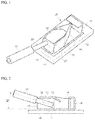
- FIG. 1 is a perspective view showing a related-art connector, that is, the poke-in connector of the prior art document
- FIG. 2 is a cross-sectional view in I-I direction showing a wire insertion structure for the connector of FIG. 1 .
- the connector of the prior art document is formed of the single plate structure without a molding portion, and thus may be easily mounted on a substrate of a small size, and has the advantage of contributing to miniaturization of electric devices.
- the one pair of support plates 13 are coupled to each other by the mounting plate 11 on the lower side, but are physically separated between the pickup plate 15 and the support plate 13 on the other side on the upper side. Accordingly, when the wire 30 is repeatedly connected and pulled out between the one pair of locking terminals 14, the one pair of support plates 13 and the one pair of locking terminals 14 easily suffer from plastic deformation, and thus there is a disadvantage that reliability and durability of contact are degraded.
- the mounting plate 11, the one pair of support plates 13, and a front end of the pickup plate 15 provide the wire insertion port 12 on the same plane in the vertical direction.
- the wire 30 is inserted into the connector 10 in a direction of being tilted slightly.
- the related-art connector 10 has a disadvantage that a sheath 31 surrounding the wire 30 collides or interferes with an end of the pickup plate 15 on the upper side during the wire insertion process as shown in FIG. 2 , and it is difficult to connect the wire.
- the wire 30 should be inserted only at a horizontal tilt angle ⁇ 1 of about 8°or less.
- the present disclosure has been suggested to solve the above-mentioned problems, and an object of the present disclosure is to provide a wire to board poke-in connector of a single plate structure, which removes a molding portion of the connector and is advantageous to miniaturization of electric devices, and can enhance reliability of connection.
- the poke-in connector of the present disclosure has a wire connection space formed therein by bending a plate of a sheet shape in a container shape, and has a wire insertion port formed at a front thereof.
- the poke-in connector includes: a mounting plate mounted on a substrate; a first support plate bending upward from an end of the mounting plate; a pickup plate bending from an end of the first support plate to face the mounting plate; a second support plate bending from an end of the pickup plate to face the first support plate, and having an end mounted on the substrate; and connection plates bending from rear ends of the first support plate and the second support plate toward the wire insertion space, and connecting a wire inserted into the wire connection space.
- the second support plate may have a mounting terminal bending from an end thereof toward the mounting plate, and the mounting terminal may be mounted on the substrate.
- connection plates may have a two-step bending structure including elastic portions bending from rear ends of the first support plate and the second support plate, and locking portions bending from ends of the elastic portions.
- the poke-in connector of the present disclosure may further include a blocking plate bending upward from a rear end of the mounting plate to block excessive insertion of the wire.
- the poke-in connector of the present disclosure is formed by bending a plate of a sheet shape of a single structure in a container shape, and mounting both ends on a substrate. Therefore, the poke-in connector can enhance a coupling force with the substrate, and can be advantageously applied to a substrate or an electric device which is made smaller.
- FIG. 3 is a perspective view showing an example of a connector being mounted on a substrate according to an exemplary embodiment of the present disclosure.
- the connector 100 according to an embodiment of the present disclosure accommodates a wire 30 while being mounted on a substrate 20, and electrically connects the wire 30 and the substrate 20, and is mounted on the substrate 20 without a separate molding portion.
- the connector 100 is formed in a container shape by bending a plate of a sheet shape, processed into a predetermined shape by extruding, at a predetermined location, and provides a wire insertion port 100a having one side opened.
- the substrate 20 may have various elements mounted therein for driving an electric device, and may have circuits printed on a surface thereof to electrically connect the elements, and in particular, may have a mounting pad 21 to allow the connector 100 to be mounted thereon.
- the wire 30 is exposed to the outside of an insulation sheath 31 by a predetermined length, and is inserted into the connector 100.
- the connector 100 is mounted on the mounting pad 21 of the substrate 20 by a process such as soldering, etc., and the wire 30 is inserted through the wire insertion port 100a and then is locked, such that an electrical connection between the substrate 20 and the wire 30 is achieved.
- FIG. 4 is a perspective view showing the connector according to an exemplary embodiment of the present disclosure, and specifically, is a partial cutaway perspective view showing an interior structure
- FIG. 5 is a top view showing the connector of FIG. 4
- FIG. 6 is a perspective view of the connector of FIG. 4 as viewed from the wire insertion port.
- the connector 100 of the present disclosure is formed by extruding and bending a conductive metal plate, and includes a mounting plate 110 fixed to the substrate 20, one pair of support plates 130 formed on both side portions of the mounting plate in a vertical direction, and a pickup plate 150 connecting upper ends of the one pair of support plates to each other.
- the connector 100 of the above-described configuration accommodates the wire 30 in a wire connection space 100b formed among the mounting plate 110, the one pair of support plates 130, and the pickup plate 150.
- a direction in which the insertion of the wire starts is referred to as a front
- a direction in which the insertion of the wire ends is referred to as a rear.
- the connector 100 of the above-described configuration is a plate of a sheet shape of a single structure, and the plate of the sheet shape continuously forms the mounting plate 110 formed in the horizontal direction in parallel with a surface of the substrate 20, a first support plate 130-1 bending upward from one side end (for example, a right side end on the drawing) of the mounting plate 110, the pickup plate 150 bending from an upper end of the first support plate 130-1 in the horizontal direction to face the mounting plate 110, and a second support plate 130-2 bending downward from the other side end (for example, a left side end on the drawing) of the pickup plate 150 to face the first support plate 130-1.
- the connector 100 of the present disclosure is formed in a rectangular container shape by bending the plate of the sheet shape, and provides the wire connection space 100b therein, in which connection and locking of the wire 30 are achieved, and provides the wire insertion port 100a formed at the front of the wire connection space 100b to allow the wire 30 to be inserted therethrough.
- the mounting plate 110 has a lower surface mounted on the mounting pad 21 of the substrate 20, and is electrically connected therewith, and simultaneously, allows the connector 110 to be stably coupled to the substrate 20.
- the mounting plate 110 may be coupled to the mounting pad 21 by soldering, and soldering is performed along an edge of the plate of the sheet shape, thereby stably maintaining coupling with the substrate 20.
- the mounting plate 110 has a blocking plate 120 formed by bending upward an end of the rear thereof to prevent excessive insertion of the wire 30, and has a shielding wall 121 formed by bending and protruding from an upper end and left and right ends of the blocking plate 120 toward the front to shield the wire connection space 100b.
- the shielding wall 121 may have a penetrating hole 122 formed thereon to check a state in which a locking portion 142 and the wire 30 are connected with each other in the wire connection space 100b, as shown in FIG. 5 , and the penetrating hole 122 may be formed on the upper shielding wall 121.
- the upper shielding wall 122 has a stopper surface 123 extended toward the front to prevent excessive insertion of a release tool 40 (see FIG. 9 ), which will be described below.
- the support plates 130 are formed of one pair of plates, including the first support plate 130-1 bending upward from the right side end of the mounting plate 110 in a substantially vertical direction, and the second support plate 130-2 bending downward from the left side end of the pickup plate 150 in a substantially vertical direction, and the first support plate 130-1 and the second support plate 130-2 faces each other to form a symmetrical structure.
- Each of the support plates 130 has a connection plate 140 formed at the rear end thereof and bending toward the wire connection space 100b inside by a predetermined tilt angle.
- connection plates 140 are separated from the mounting plate 110 and the pickup plate 150, and have elasticity with reference to an axis of the support plate 130, and guide the insertion of the wire 30, are electrically connected with the wire 30, and simultaneously, locks the wire 30 to prevent the wire 30 from being released.
- connection plates 140 includes an elastic portion 141 bending from an end of the support plate 130 firstly, and a locking portion 142 bending from an end of the elastic portion 141 secondarily.
- a coupling portion 143 is further interposed between the elastic portion 141 and the locking portion 142 in parallel with the support plate 130, thereby coupling the elastic portion 141 and the locking portion 142 to each other.
- each of the connection plates 140 forms at least two-step bending structure , and the connection plate of the two-step bending structure elastically presses the wire 30 on the locking portion 142 of the end with a stronger force in comparison to a one-step bending structure, and is more resistant even to plastic deformation.
- plastic deformation of the locking portion according to a restoring state after a push is applied is as follows.
- the one-step bending structure shows plastic deformation of 0.078 mm, but the two-step bending structure shows plastic deformation of 0.011 mm. Therefore, the locking portion 142 of the connection plate 140 of the two-step bending structure shows an excellent property even in response to plastic deformation.
- each of the connection plates 140 includes an unlocking portion 144 bending inward from an upper end of the coupling portion 143 in an inverted-U shape (' ⁇ ').
- the one pair of unlocking portions 144 has a predetermined gap therebetween and curve inward to correspond to each other.
- the release tool 40 is inserted between the unlocking portions 144, the one pair of connection plates 140 are spaced apart from each other, such that the wire 30 can be easily pulled out from the connection plates 140.
- each of the support plates 130 may have a concavo-convex portion 131 formed on a side surface thereof coupled to the connection plate 140.
- the concavo-convex portion 131 is concavely recessed or convexly protrudes on the surface of the plate where the support plate 130 and the connection plate 140 are coupled to each other, and adds a tolerance to elastic deformation of the connection plate 140 made with reference to the axis of the end of the support plate 130, such that the connection plate 140 has a stronger elastic pressure.
- the pickup plate 150 bends inward from the upper end of the first support plate 130-1 in a substantially horizontal direction.
- the pickup plate 150 faces the mounting plate 110 in parallel, and provides a pickup surface formed on an upper surface thereof to allow the connector 100 to be adsorbed onto a mounting tool.
- the pickup plate 150 has a stopper surface 151 protruding and extending from an end of the rear thereof to prevent excessive insertion of the release tool 40.
- the second support plate 130-2 bends from the left side end of the pickup plate 150, and faces the first support plate 130-1 in parallel, and has a mounting terminal 132 bending inward from a lower end thereof.
- the mounting plate 110 provides a space to avoid the mounting terminal 132.
- the mounting plate 110 and the mounting terminal 132 form the same plane with a predetermined gap therebetween, and are soldered along their respective edges 110-1, 132-1 and are mounted on the mounting pad 21.
- the connector 100 of the present disclosure forms a sealing structure by being formed by bending the plate of the sheet shape in the container shape, and mounting both side ends on the substrate 20. Therefore, even when the wire 30 is repeatedly connected or pulled out, plastic deformation does not almost appear and reliability and durability of contact can be enhanced.
- FIG. 7 is a front view showing a wire insertion structure for the connector of the present disclosure
- FIG. 8 is a front view showing a wire bending structure for the connector of the present disclosure.
- the mounting plate 110 on the lower side, the one pair of support plates 130 on both sides, and the pickup plate 150 on the upper side form the container shape, and have the wire insertion port 100a formed at the front in a substantial rectangular shape and opened to the front.
- an avoidance recess 100c is formed on the wire insertion port 100a, such that an end B of the pickup plate 150 is further stepped back than an end B of the mounting plate 110.
- the avoidance recess 100c may be formed by giving a slope to an end of the support plate 130 coupling the end A of the mounting plate 110 and the end B of the pickup plate 150, or by positioning a second vertical end 134 on the upper side further back than a first vertical end 133 on the lower side, and aligning the end B of the pickup plate 150 with an upper end of the support plate 130.
- the avoidance recess 100c prevents the wire sheath 31 from colliding or interfering with the upper end of the connector 100 (that is, an end of the pickup plate) when the wire 30 is inserted in a tilt direction as shown in FIG. 7 . Accordingly, the avoidance recess 100c increases a tilt angle ⁇ 2 of the wire 30 being inserted with respect to the horizontal direction, thereby making it easy to connect the wire 30.
- the wire 30 is assembled with an electric device in a state in which the wire 30 is connected to the connector 100 and is bent upward by about 90°.
- the wire sheath 31 may collide and interfere with the end B of the pickup plate 150, and the end of the pickup plate 150 is subject to an upward external force by the collision or interference, and the upward external force may be transmitted to the mounting plate 110 and the mounting terminal 132 on the lower surface, and may damage soldering to the substrate 20 or may attenuate a coupling force between the connector 100 and the substrate 20.
- FIG. 9 is a perspective view showing an unlocking structure for the connector of the present disclosure
- FIG. 10 is a perspective view showing a connector according to another embodiment of the present disclosure.
- the connected wire 30 is locked into the wire connection space 100b by a sharp end of the locking portion 142, and is not easily pulled out. This is because the one pair of locking portions 142 presses both surfaces of the wire 30 with a strong elastic force. Accordingly, to pull out the wire 30, the one pair of locking portions 142 should be spaced apart from each other.
- the stopper surfaces 151, 123 are formed on ends of the pickup plates 150 and the shielding wall 121, respectively, to prevent the excessive insertion of the release tool 40 and to protect the wire 30.
- the unlocking portions 144 may be formed to have one pair of semicircular cross sections corresponding to each other to correspond to an exterior of the release tool 40.
- a means for unlocking the wire 30 may be directly formed on the connector 100 without using a separate tool.
- the pickup plate 150 may have a pressing portion 152 extending from a rear end thereof, and may have an insertion protrusion 154 formed on a lower side of an end of the pressing portion 152 in a wedge shape.
- the pressing portion 152 is coupled to the pickup plate 150 by an elastic piece 153 forming a curved shape.
- the pressing portion 152 formed on the connector 100 as described above may be formed by being extended to the front from an upper end of the blocking plate 120, and the insertion protrusion 154 may be formed on both side portions of the pressing portion 152.
- connector 110 mounting plate 120: blocking plate 130: support plate 130-1: first support plate 130-2: second support plate 132: mounting terminal 140: connection plate 141: elastic portion 142: locking portion 143: coupling portion 144: unlocking portion 150: pickup plate
Abstract
Description
- The present disclosure relates to a wire to board connector, and more particularly, to a wire to board poke-in connector of a single plate structure, which can be stably mounted on a substrate and is not provided with a separate molding portion.
- In general, a wire to board connector refers to a connector that is used to connect a wire of an electric/electronic device and a printed circuit board with each other. One of the connectors that brings a wire into contact with a terminal and locks the wire into the terminal simply by inserting the wire into the terminal is referred to as a poke-in connector.
- A related-art general poke-in connector has a structure in which a molding portion is coupled to a contact terminal mounted on a substrate while surrounding the contact terminal, the contact terminal and a wire insertion port of the molding portion are arranged in the same direction, and a wire is inserted in a horizontal direction through the wire insertion port, and is connected to the contact terminal. The molding portion guides the insertion of the wire and prevents unnecessary interference between the wire and the contact terminal, and stably maintains mounting of the contact terminal, thereby enhancing reliability of electrical contact.
- As electric devices are miniaturized in recent years, sizes of substrates on which connectors are mounted are getting smaller. However, the related-art connector having the molding portion coupled to the contact terminal is an impediment to miniaturization of the substrate and the electric device because the molding portion occupies relatively large area and space on the substrate. As a solution to this problem, U.S. Patent Registration No.
US 8,721,376B1 introduces a poke-in connector of a signal plate structure, which is formed of only a contact terminal, with the title "SINGLE ELEMENT WIRE TO BARD CONNECTOR." -
FIG. 1 is a perspective view showing a related-art connector, that is, the poke-in connector of the prior art document, andFIG. 2 is a cross-sectional view in I-I direction showing a wire insertion structure for the connector ofFIG. 1 . - Referring to
FIG. 1 , theconnector 10 of the prior art document is formed of a single plate, and includes a mounting plate 11 soldered to asubstrate 20, one pair ofsupport plates 13 having awire insertion port 12 formed at a front portion thereof, and bending upward from both sides of the mounting plate 11, and apickup plate 15 which bends when thesupport plate 13 on one side shields an upper portion of thewire insertion port 12. Herein, the mounting plate 11 provides a blockingwall 16 formed by bending upward the opposite end of the wire insertion port 11 to block the insertion of awire 30, and the one pair ofsupport plates 13 facing each other providelocking terminals 14, respectively, having insertion direction ends bending inward. - The connector of the prior art document is formed of the single plate structure without a molding portion, and thus may be easily mounted on a substrate of a small size, and has the advantage of contributing to miniaturization of electric devices.
- However, in the related-art connector, the one pair of
support plates 13 are coupled to each other by the mounting plate 11 on the lower side, but are physically separated between thepickup plate 15 and thesupport plate 13 on the other side on the upper side. Accordingly, when thewire 30 is repeatedly connected and pulled out between the one pair oflocking terminals 14, the one pair ofsupport plates 13 and the one pair oflocking terminals 14 easily suffer from plastic deformation, and thus there is a disadvantage that reliability and durability of contact are degraded. - In addition, in the related-
art connector 10, the mounting plate 11, the one pair ofsupport plates 13, and a front end of thepickup plate 15 provide thewire insertion port 12 on the same plane in the vertical direction. In general, in a poke-in connector in a horizontal connection direction, thewire 30 is inserted into theconnector 10 in a direction of being tilted slightly. Accordingly, the related-art connector 10 has a disadvantage that asheath 31 surrounding thewire 30 collides or interferes with an end of thepickup plate 15 on the upper side during the wire insertion process as shown inFIG. 2 , and it is difficult to connect the wire. In order to prevent collision or interference between theconnector 10 and thewire sheath 31 as described above, thewire 30 should be inserted only at a horizontal tilt angle θ1 of about 8°or less. - The present disclosure has been suggested to solve the above-mentioned problems, and an object of the present disclosure is to provide a wire to board poke-in connector of a single plate structure, which removes a molding portion of the connector and is advantageous to miniaturization of electric devices, and can enhance reliability of connection.
- To achieve the above-described object, the poke-in connector of the present disclosure has a wire connection space formed therein by bending a plate of a sheet shape in a container shape, and has a wire insertion port formed at a front thereof. The poke-in connector includes: a mounting plate mounted on a substrate; a first support plate bending upward from an end of the mounting plate; a pickup plate bending from an end of the first support plate to face the mounting plate; a second support plate bending from an end of the pickup plate to face the first support plate, and having an end mounted on the substrate; and connection plates bending from rear ends of the first support plate and the second support plate toward the wire insertion space, and connecting a wire inserted into the wire connection space.
- In addition, the second support plate may have a mounting terminal bending from an end thereof toward the mounting plate, and the mounting terminal may be mounted on the substrate.
- In addition, the wire insertion port may have an avoidance recess, such that an end of the pickup plate is further stepped back than an end of the mounting plate.
- The connection plates may have a two-step bending structure including elastic portions bending from rear ends of the first support plate and the second support plate, and locking portions bending from ends of the elastic portions.
- In addition, the poke-in connector of the present disclosure may further include a blocking plate bending upward from a rear end of the mounting plate to block excessive insertion of the wire.
- The poke-in connector of the present disclosure is formed by bending a plate of a sheet shape of a single structure in a container shape, and mounting both ends on a substrate. Therefore, the poke-in connector can enhance a coupling force with the substrate, and can be advantageously applied to a substrate or an electric device which is made smaller.
-
-
FIG. 1 is a perspective view showing a related-art connector; -
FIG. 2 is a cross-sectional view showing a wire insertion structure for the connector ofFIG. 1 ; -
FIG. 3 is a perspective view showing an example of a connector being mounted on a substrate according to an exemplary embodiment of the present disclosure; -
FIG. 4 is a perspective view showing the connector according to an exemplary embodiment of the present disclosure; -
FIG. 5 is a top view showing the connector ofFIG. 4 ; -
FIG. 6 is a perspective view of the connector ofFIG. 4 as viewed from a wire insertion port; -
FIG. 7 is a front view showing a wire insertion structure for the connector of the present disclosure; -
FIG. 8 is a front view showing a wire bending structure for the connector of the present disclosure; -
FIG. 9 is a perspective view showing an unlocking structure for the connector of the present disclosure; and -
FIG. 10 is a perspective view showing a connector according to another exemplary embodiment of the present disclosure; - The present disclosure and the technical objects achieved by embodiments of the present disclosure will be more apparent by preferred embodiments of the present disclosure which will be described below. Hereinafter, preferred embodiments of the present disclosure will be described in detail with reference to the accompanying drawings. In the description of the present disclosure, expressions "front," "rear," "upper," "lower," "left," "right," "first," and "second" are expressions according to relative locations or directions, and the configuration of the invention is not limited by their dictionary definitions.
-
FIG. 3 is a perspective view showing an example of a connector being mounted on a substrate according to an exemplary embodiment of the present disclosure. As shown in the drawing, theconnector 100 according to an embodiment of the present disclosure accommodates awire 30 while being mounted on asubstrate 20, and electrically connects thewire 30 and thesubstrate 20, and is mounted on thesubstrate 20 without a separate molding portion. - The
connector 100 is formed in a container shape by bending a plate of a sheet shape, processed into a predetermined shape by extruding, at a predetermined location, and provides awire insertion port 100a having one side opened. Thesubstrate 20 may have various elements mounted therein for driving an electric device, and may have circuits printed on a surface thereof to electrically connect the elements, and in particular, may have amounting pad 21 to allow theconnector 100 to be mounted thereon. Thewire 30 is exposed to the outside of aninsulation sheath 31 by a predetermined length, and is inserted into theconnector 100. - The
connector 100 is mounted on themounting pad 21 of thesubstrate 20 by a process such as soldering, etc., and thewire 30 is inserted through thewire insertion port 100a and then is locked, such that an electrical connection between thesubstrate 20 and thewire 30 is achieved. -
FIG. 4 is a perspective view showing the connector according to an exemplary embodiment of the present disclosure, and specifically, is a partial cutaway perspective view showing an interior structure,FIG. 5 is a top view showing the connector ofFIG. 4 , andFIG. 6 is a perspective view of the connector ofFIG. 4 as viewed from the wire insertion port. - Referring to
FIG. 4 , theconnector 100 of the present disclosure is formed by extruding and bending a conductive metal plate, and includes amounting plate 110 fixed to thesubstrate 20, one pair ofsupport plates 130 formed on both side portions of the mounting plate in a vertical direction, and apickup plate 150 connecting upper ends of the one pair of support plates to each other. Theconnector 100 of the above-described configuration accommodates thewire 30 in awire connection space 100b formed among themounting plate 110, the one pair ofsupport plates 130, and thepickup plate 150. Herein, a direction in which the insertion of the wire starts is referred to as a front, and a direction in which the insertion of the wire ends is referred to as a rear. - The
connector 100 of the above-described configuration is a plate of a sheet shape of a single structure, and the plate of the sheet shape continuously forms themounting plate 110 formed in the horizontal direction in parallel with a surface of thesubstrate 20, a first support plate 130-1 bending upward from one side end (for example, a right side end on the drawing) of themounting plate 110, thepickup plate 150 bending from an upper end of the first support plate 130-1 in the horizontal direction to face themounting plate 110, and a second support plate 130-2 bending downward from the other side end (for example, a left side end on the drawing) of thepickup plate 150 to face the first support plate 130-1. Accordingly, theconnector 100 of the present disclosure is formed in a rectangular container shape by bending the plate of the sheet shape, and provides thewire connection space 100b therein, in which connection and locking of thewire 30 are achieved, and provides thewire insertion port 100a formed at the front of thewire connection space 100b to allow thewire 30 to be inserted therethrough. - Specifically, the
mounting plate 110 has a lower surface mounted on themounting pad 21 of thesubstrate 20, and is electrically connected therewith, and simultaneously, allows theconnector 110 to be stably coupled to thesubstrate 20. Themounting plate 110 may be coupled to themounting pad 21 by soldering, and soldering is performed along an edge of the plate of the sheet shape, thereby stably maintaining coupling with thesubstrate 20. - In addition, the
mounting plate 110 has a blockingplate 120 formed by bending upward an end of the rear thereof to prevent excessive insertion of thewire 30, and has ashielding wall 121 formed by bending and protruding from an upper end and left and right ends of the blockingplate 120 toward the front to shield thewire connection space 100b. Theshielding wall 121 may have a penetratinghole 122 formed thereon to check a state in which alocking portion 142 and thewire 30 are connected with each other in thewire connection space 100b, as shown inFIG. 5 , and the penetratinghole 122 may be formed on theupper shielding wall 121. In addition, theupper shielding wall 122 has astopper surface 123 extended toward the front to prevent excessive insertion of a release tool 40 (seeFIG. 9 ), which will be described below. - The
support plates 130 are formed of one pair of plates, including the first support plate 130-1 bending upward from the right side end of the mountingplate 110 in a substantially vertical direction, and the second support plate 130-2 bending downward from the left side end of thepickup plate 150 in a substantially vertical direction, and the first support plate 130-1 and the second support plate 130-2 faces each other to form a symmetrical structure. Each of thesupport plates 130 has aconnection plate 140 formed at the rear end thereof and bending toward thewire connection space 100b inside by a predetermined tilt angle. The one pair ofconnection plates 140 are separated from the mountingplate 110 and thepickup plate 150, and have elasticity with reference to an axis of thesupport plate 130, and guide the insertion of thewire 30, are electrically connected with thewire 30, and simultaneously, locks thewire 30 to prevent thewire 30 from being released. - Each of the
connection plates 140 includes anelastic portion 141 bending from an end of thesupport plate 130 firstly, and a lockingportion 142 bending from an end of theelastic portion 141 secondarily. Acoupling portion 143 is further interposed between theelastic portion 141 and the lockingportion 142 in parallel with thesupport plate 130, thereby coupling theelastic portion 141 and the lockingportion 142 to each other. Accordingly, each of theconnection plates 140 forms at least two-step bending structure , and the connection plate of the two-step bending structure elastically presses thewire 30 on the lockingportion 142 of the end with a stronger force in comparison to a one-step bending structure, and is more resistant even to plastic deformation.[Table 1] Type Two-step bending One-step bending Push (mm) 0.3 Force (N) 6.012 3.975 Plasticity (mm) 0.011 0.078 - As shown in table 1 above, when the end of the locking portion is pushed to have deformation toward one side by a width of 0.3 mm on the assumption that the wire is inserted, deformation is achieved by a force of 3.975 N in the one-step bending structure, but in the two-step bending structure, the deformation by the same width is achieved only when a force of 6.012 N is applied. Therefore, it can be seen that the locking
portion 142 of theconnection plate 140 of the two-step bending structure shows a relatively larger pressure. - In addition, plastic deformation of the locking portion according to a restoring state after a push is applied is as follows. The one-step bending structure shows plastic deformation of 0.078 mm, but the two-step bending structure shows plastic deformation of 0.011 mm. Therefore, the locking
portion 142 of theconnection plate 140 of the two-step bending structure shows an excellent property even in response to plastic deformation. - In addition, each of the
connection plates 140 includes an unlockingportion 144 bending inward from an upper end of thecoupling portion 143 in an inverted-U shape ('∩'). The one pair of unlockingportions 144 has a predetermined gap therebetween and curve inward to correspond to each other. When therelease tool 40 is inserted between the unlockingportions 144, the one pair ofconnection plates 140 are spaced apart from each other, such that thewire 30 can be easily pulled out from theconnection plates 140. - In addition, each of the
support plates 130 may have a concavo-convex portion 131 formed on a side surface thereof coupled to theconnection plate 140. The concavo-convex portion 131 is concavely recessed or convexly protrudes on the surface of the plate where thesupport plate 130 and theconnection plate 140 are coupled to each other, and adds a tolerance to elastic deformation of theconnection plate 140 made with reference to the axis of the end of thesupport plate 130, such that theconnection plate 140 has a stronger elastic pressure. - The
pickup plate 150 bends inward from the upper end of the first support plate 130-1 in a substantially horizontal direction. Thepickup plate 150 faces the mountingplate 110 in parallel, and provides a pickup surface formed on an upper surface thereof to allow theconnector 100 to be adsorbed onto a mounting tool. In addition, thepickup plate 150 has astopper surface 151 protruding and extending from an end of the rear thereof to prevent excessive insertion of therelease tool 40. - Referring to
FIG. 6 , the second support plate 130-2 bends from the left side end of thepickup plate 150, and faces the first support plate 130-1 in parallel, and has a mountingterminal 132 bending inward from a lower end thereof. To achieve this, the mountingplate 110 provides a space to avoid the mountingterminal 132. The mountingplate 110 and the mountingterminal 132 form the same plane with a predetermined gap therebetween, and are soldered along their respective edges 110-1, 132-1 and are mounted on the mountingpad 21. Accordingly, theconnector 100 of the present disclosure forms a sealing structure by being formed by bending the plate of the sheet shape in the container shape, and mounting both side ends on thesubstrate 20. Therefore, even when thewire 30 is repeatedly connected or pulled out, plastic deformation does not almost appear and reliability and durability of contact can be enhanced. -
FIG. 7 is a front view showing a wire insertion structure for the connector of the present disclosure, andFIG. 8 is a front view showing a wire bending structure for the connector of the present disclosure. - In the
connector 100 of the present disclosure, the mountingplate 110 on the lower side, the one pair ofsupport plates 130 on both sides, and thepickup plate 150 on the upper side form the container shape, and have thewire insertion port 100a formed at the front in a substantial rectangular shape and opened to the front. In this case, as shown inFIGs. 7 and 8 , an avoidance recess 100c is formed on thewire insertion port 100a, such that an end B of thepickup plate 150 is further stepped back than an end B of the mountingplate 110. The avoidance recess 100c may be formed by giving a slope to an end of thesupport plate 130 coupling the end A of the mountingplate 110 and the end B of thepickup plate 150, or by positioning a secondvertical end 134 on the upper side further back than a firstvertical end 133 on the lower side, and aligning the end B of thepickup plate 150 with an upper end of thesupport plate 130. - The avoidance recess 100c prevents the
wire sheath 31 from colliding or interfering with the upper end of the connector 100 (that is, an end of the pickup plate) when thewire 30 is inserted in a tilt direction as shown inFIG. 7 . Accordingly, the avoidance recess 100c increases a tilt angle θ2 of thewire 30 being inserted with respect to the horizontal direction, thereby making it easy to connect thewire 30. - In addition, as shown in
FIG. 8 , thewire 30 is assembled with an electric device in a state in which thewire 30 is connected to theconnector 100 and is bent upward by about 90°. In this case, thewire sheath 31 may collide and interfere with the end B of thepickup plate 150, and the end of thepickup plate 150 is subject to an upward external force by the collision or interference, and the upward external force may be transmitted to the mountingplate 110 and the mountingterminal 132 on the lower surface, and may damage soldering to thesubstrate 20 or may attenuate a coupling force between theconnector 100 and thesubstrate 20. Accordingly, the avoidance recess 100c minimizes the collision and interference of thewire sheath 31 with the end of thepickup plate 150 when thewire 30 is bent upward, thereby enhancing reliability and durability of contact of theconnector 100.[Table 2] Type Example Comparison example Push (mm) 0.5 Force (N) 97.27 87.08 Plasticity (mm) 0.2193 0.3148 - As shown in table 2 above, when the end of the pickup plate of the wire insertion port is pushed to have deformation toward the upper side by a height of 0.5 mm on the assumption that the connected wire is bent by 90°, deformation is achieved by a force of 87.08 N in a pickup plate (comparison example) of a box structure without an avoidance recess, but in a pickup plate (example) of a stepped structure having an avoidance recess, the deformation by the same height is achieved when a force of 97.27 N is applied. In addition, plastic deformation according to a restoring state after deformation is applied is as follows. The comparison example shows plastic deformation of 0.3148, but the example shows plastic deformation of 0.2193.
- Based on the above result, when the same external force is applied to the upper side of the wire insertion port, relatively small deformation may be made on the upper end of the connector having the avoidance recess formed thereon, in comparison to the upper end of the connector without the avoidance recess, and as a result, a relatively small external force is transmitted to the connector having the avoidance recess, and thus reliability and durability of contact of the connector can be enhanced.
-
FIG. 9 is a perspective view showing an unlocking structure for the connector of the present disclosure, andFIG. 10 is a perspective view showing a connector according to another embodiment of the present disclosure. - Referring to
FIG. 9 , the connectedwire 30 is locked into thewire connection space 100b by a sharp end of the lockingportion 142, and is not easily pulled out. This is because the one pair of lockingportions 142 presses both surfaces of thewire 30 with a strong elastic force. Accordingly, to pull out thewire 30, the one pair of lockingportions 142 should be spaced apart from each other. - To achieve this, the present disclosure has the one pair of unlocking
portions 144 formed on upper ends of thecoupling portions 143 in a curved shape, and facing each other to space the lockingportions 142 apart from each other. Accordingly, when therelease tool 40 is inserted between the one pair of unlockingportions 144 as shown in the drawing, ends of the one pair of lockingportions 142 are spaced apart from each other with the unlockingportions 144, such that thewire 30 can be easily pulled out. - In addition, when the
release tool 40 is excessively inserted between the unlockingportions 144, an end of therelease tool 40 presses thewire 30 and rather makes it difficult to pull out thewire 30 or damages thewire 30. Accordingly, the stopper surfaces 151, 123 are formed on ends of thepickup plates 150 and the shieldingwall 121, respectively, to prevent the excessive insertion of therelease tool 40 and to protect thewire 30. - In addition, in the
connector 100 of the present disclosure, the unlockingportions 144 may be formed to have one pair of semicircular cross sections corresponding to each other to correspond to an exterior of therelease tool 40. - Meanwhile, as shown in
FIG. 10 , a means for unlocking thewire 30 may be directly formed on theconnector 100 without using a separate tool. - Specifically, the
pickup plate 150 may have apressing portion 152 extending from a rear end thereof, and may have aninsertion protrusion 154 formed on a lower side of an end of thepressing portion 152 in a wedge shape. In addition, thepressing portion 152 is coupled to thepickup plate 150 by anelastic piece 153 forming a curved shape. When thepressing portion 152 is pressed with thewire 152 being connected to theconnector 100 of the above-described configuration, theinsertion protrusion 154 is inserted between the one pair of lockingportions 142, and spaces the lockingportions 142 apart from each other, such that thewire 30 is unlocked and is easily pulled out. - In addition, the
pressing portion 152 formed on theconnector 100 as described above may be formed by being extended to the front from an upper end of the blockingplate 120, and theinsertion protrusion 154 may be formed on both side portions of thepressing portion 152. - Although the present disclosure has been described with reference to embodiments illustrated in the drawings, it will be understood by an ordinary person skilled in the related art that various changes can be made therefrom and other equivalent embodiments are possible.
Explanation of Signs 100: connector 110: mounting plate 120: blocking plate 130: support plate 130-1: first support plate 130-2: second support plate 132: mounting terminal 140: connection plate 141: elastic portion 142: locking portion 143: coupling portion 144: unlocking portion 150: pickup plate
Claims (6)
- A poke-in connector which has a wire connection space formed therein by bending a plate of a sheet shape in a container shape, and has a wire insertion port formed at a front thereof, the poke-in connector comprising:a mounting plate mounted on a substrate;a first support plate bending upward from an end of the mounting plate;a pickup plate bending from an end of the first support plate to face the mounting plate;a second support plate bending from an end of the pickup plate to face the first support plate, and having an end mounted on the substrate; andconnection plates bending from rear ends of the first support plate and the second support plate toward the wire insertion space, and connecting a wire inserted into the wire connection space.
- The poke-in connector of claim 1,
wherein the second support plate has a mounting terminal bending from an end thereof toward the mounting plate, and the mounting terminal is mounted on the substrate. - The poke-in connector of claim 1,
wherein the wire insertion port has an avoidance recess, such that an end of the pickup plate is further stepped back than an end of the mounting plate. - The poke-in connector of any one of claims 1 to 3,
wherein the connection plates have a two-step bending structure comprising elastic portions bending from rear ends of the first support plate and the second support plate, and locking portions bending from ends of the elastic portions. - The poke-in connector of claim 4,
wherein the elastic portion and the locking portion are coupled to each other by a coupling portion. - The poke-in connector of any one of claims 1 to 3, further comprising
a blocking plate bending upward from a rear end of the mounting plate to block excessive insertion of the wire.
Applications Claiming Priority (1)
| Application Number | Priority Date | Filing Date | Title |
|---|---|---|---|
| KR1020170088523A KR102011845B1 (en) | 2017-07-12 | 2017-07-12 | Poke-in Connector |
Publications (1)
| Publication Number | Publication Date |
|---|---|
| EP3429031A1 true EP3429031A1 (en) | 2019-01-16 |
Family
ID=62874809
Family Applications (1)
| Application Number | Title | Priority Date | Filing Date |
|---|---|---|---|
| EP18182307.1A Withdrawn EP3429031A1 (en) | 2017-07-12 | 2018-07-06 | Poke-in connector |
Country Status (4)
| Country | Link |
|---|---|
| US (1) | US20190020143A1 (en) |
| EP (1) | EP3429031A1 (en) |
| KR (1) | KR102011845B1 (en) |
| CN (1) | CN109256628A (en) |
Cited By (2)
| Publication number | Priority date | Publication date | Assignee | Title |
|---|---|---|---|---|
| TWI702759B (en) * | 2019-11-25 | 2020-08-21 | 陳石火 | Wire-to-board connector |
| CN113178715A (en) * | 2020-01-27 | 2021-07-27 | Bjb两合公司 | Electric connection clamp |
Citations (3)
| Publication number | Priority date | Publication date | Assignee | Title |
|---|---|---|---|---|
| WO2012136536A1 (en) * | 2011-04-08 | 2012-10-11 | Ptr Messtechnik Gmbh & Co. Kommanditgesellschaft | Conductor terminal for two opposite printed circuit boards |
| US8721376B1 (en) | 2012-11-01 | 2014-05-13 | Avx Corporation | Single element wire to board connector |
| US20150311603A1 (en) * | 2014-04-29 | 2015-10-29 | Avx Corporation | Interlocking poke home contact |
Family Cites Families (21)
| Publication number | Priority date | Publication date | Assignee | Title |
|---|---|---|---|---|
| DE3882983D1 (en) * | 1988-08-05 | 1993-09-09 | Weidmueller Interface | SOCKET CONTACT. |
| JP3119418B2 (en) * | 1994-04-20 | 2000-12-18 | 矢崎総業株式会社 | Terminal for waterproof connector |
| US5681190A (en) * | 1995-05-23 | 1997-10-28 | Cardell Corporation | Torsional blade receptacle |
| DE69622369T2 (en) * | 1996-03-11 | 2003-03-27 | Molex Inc | Electrical socket for pen with high contact force |
| JP4013151B2 (en) * | 2004-04-13 | 2007-11-28 | 住友電装株式会社 | Female terminal bracket |
| JP4514645B2 (en) * | 2004-07-12 | 2010-07-28 | タイコエレクトロニクスジャパン合同会社 | Female terminal |
| CN201041875Y (en) * | 2007-05-07 | 2008-03-26 | 富士康(昆山)电脑接插件有限公司 | Electric connector |
| JP5906537B2 (en) * | 2010-09-06 | 2016-04-20 | 矢崎総業株式会社 | Conductive path structure and wire harness |
| WO2014125963A1 (en) * | 2013-02-12 | 2014-08-21 | 矢崎総業株式会社 | Connector |
| US8968022B2 (en) * | 2013-02-25 | 2015-03-03 | Tyco Electronics Corporation | Electrical connector having poke-in wire contact |
| KR101390960B1 (en) * | 2013-03-29 | 2014-05-02 | 몰렉스 인코포레이티드 | Poke in connector |
| KR101978927B1 (en) * | 2013-04-11 | 2019-05-15 | 몰렉스 엘엘씨 | Poke in connector |
| JP5604575B1 (en) * | 2013-09-25 | 2014-10-08 | イリソ電子工業株式会社 | Wire conductor connection terminal |
| WO2015081986A1 (en) * | 2013-12-03 | 2015-06-11 | Fci Asia Pte.Ltd | Connector and pin receiving contact for such a connector |
| DE112015000322T5 (en) * | 2014-01-31 | 2016-11-03 | Panasonic Intellectual Property Management Co., Ltd. | Connector and connector device |
| USD781239S1 (en) * | 2014-03-25 | 2017-03-14 | Molex, Llc | Terminal fitting for electric connector |
| US9647368B2 (en) * | 2014-09-22 | 2017-05-09 | Ideal Industries, Inc. | Terminals for electrical connectors |
| TWI568114B (en) * | 2014-10-03 | 2017-01-21 | Excel Cell Electronic Co Ltd | Terminal block |
| KR20160135882A (en) * | 2015-05-18 | 2016-11-29 | (주)씨엘 | Electric connector for a power cable |
| CN204966753U (en) * | 2015-07-31 | 2016-01-13 | 泰科电子(上海)有限公司 | Connector and connector assembly |
| TWM517439U (en) * | 2015-10-16 | 2016-02-11 | Tarng Yu Entpr Co Ltd | Single element wire board connection terminal |
-
2017
- 2017-07-12 KR KR1020170088523A patent/KR102011845B1/en active IP Right Grant
-
2018
- 2018-07-06 EP EP18182307.1A patent/EP3429031A1/en not_active Withdrawn
- 2018-07-11 US US16/032,299 patent/US20190020143A1/en not_active Abandoned
- 2018-07-12 CN CN201810766484.9A patent/CN109256628A/en active Pending
Patent Citations (3)
| Publication number | Priority date | Publication date | Assignee | Title |
|---|---|---|---|---|
| WO2012136536A1 (en) * | 2011-04-08 | 2012-10-11 | Ptr Messtechnik Gmbh & Co. Kommanditgesellschaft | Conductor terminal for two opposite printed circuit boards |
| US8721376B1 (en) | 2012-11-01 | 2014-05-13 | Avx Corporation | Single element wire to board connector |
| US20150311603A1 (en) * | 2014-04-29 | 2015-10-29 | Avx Corporation | Interlocking poke home contact |
Cited By (4)
| Publication number | Priority date | Publication date | Assignee | Title |
|---|---|---|---|---|
| TWI702759B (en) * | 2019-11-25 | 2020-08-21 | 陳石火 | Wire-to-board connector |
| CN113178715A (en) * | 2020-01-27 | 2021-07-27 | Bjb两合公司 | Electric connection clamp |
| EP3855570A1 (en) * | 2020-01-27 | 2021-07-28 | BJB GmbH & Co. KG | Electrical terminal |
| US11482797B2 (en) | 2020-01-27 | 2022-10-25 | Bjb Gmbh & Co. Kg | Electrical connection terminal |
Also Published As
| Publication number | Publication date |
|---|---|
| KR20190007282A (en) | 2019-01-22 |
| CN109256628A (en) | 2019-01-22 |
| KR102011845B1 (en) | 2019-08-19 |
| US20190020143A1 (en) | 2019-01-17 |
Similar Documents
| Publication | Publication Date | Title |
|---|---|---|
| US6431914B1 (en) | Grounding scheme for a high speed backplane connector system | |
| KR102240783B1 (en) | Electrical connector device | |
| CN106410457B (en) | Electrical connector for substrate connection | |
| US9106024B2 (en) | Electrical connector with a metal plate for preventing electromagnetic interference | |
| KR101928630B1 (en) | Connector apparatus | |
| EP1825573B1 (en) | Connector guide with latch and connectors therefor | |
| US7108554B2 (en) | Electrical connector with shielding member | |
| US7651372B2 (en) | Electric connector with shields on mating housings | |
| KR20150110333A (en) | Connector | |
| US7950965B2 (en) | Electrical connector having passageways protected from contamination | |
| WO2008000145A1 (en) | Electrical connector assembly | |
| US7377821B2 (en) | Electrical connector | |
| US9722356B2 (en) | Connector | |
| US7442082B2 (en) | Shielded connector with folding arrangement ensuring perpendicularity between sidewall and bottom wall of the metal housing | |
| JP6970928B2 (en) | Electrical connector | |
| EP3429031A1 (en) | Poke-in connector | |
| US7241160B2 (en) | Shielded electrical connector for camera module | |
| JP2012146401A (en) | Connector device | |
| KR102133399B1 (en) | Poke-in Connector | |
| JP2016184505A (en) | Electrical connector for substrate connection and electrical connector device for substrate connection | |
| KR100567587B1 (en) | Electrical connector having a holddown for ground connection | |
| TWI689137B (en) | Connector for high-speed signal transmission | |
| US6666714B1 (en) | Electrical connector with terminal protector | |
| US10439306B2 (en) | Electrical contact terminal | |
| CN111082244B (en) | Connector with a plurality of connectors |
Legal Events
| Date | Code | Title | Description |
|---|---|---|---|
| PUAI | Public reference made under article 153(3) epc to a published international application that has entered the european phase |
Free format text: ORIGINAL CODE: 0009012 |
|
| AK | Designated contracting states |
Kind code of ref document: A1 Designated state(s): AL AT BE BG CH CY CZ DE DK EE ES FI FR GB GR HR HU IE IS IT LI LT LU LV MC MK MT NL NO PL PT RO RS SE SI SK SM TR |
|
| AX | Request for extension of the european patent |
Extension state: BA ME |
|
| 17P | Request for examination filed |
Effective date: 20190626 |
|
| RBV | Designated contracting states (corrected) |
Designated state(s): AL AT BE BG CH CY CZ DE DK EE ES FI FR GB GR HR HU IE IS IT LI LT LU LV MC MK MT NL NO PL PT RO RS SE SI SK SM TR |
|
| 17Q | First examination report despatched |
Effective date: 20191031 |
|
| STAA | Information on the status of an ep patent application or granted ep patent |
Free format text: STATUS: THE APPLICATION IS DEEMED TO BE WITHDRAWN |
|
| 18D | Application deemed to be withdrawn |
Effective date: 20200923 |