EP3428669B1 - Apparatus and method for detecting state of health of battery - Google Patents
Apparatus and method for detecting state of health of battery Download PDFInfo
- Publication number
- EP3428669B1 EP3428669B1 EP17762509.2A EP17762509A EP3428669B1 EP 3428669 B1 EP3428669 B1 EP 3428669B1 EP 17762509 A EP17762509 A EP 17762509A EP 3428669 B1 EP3428669 B1 EP 3428669B1
- Authority
- EP
- European Patent Office
- Prior art keywords
- battery
- detected unit
- cpu module
- time point
- loss
- Prior art date
- Legal status (The legal status is an assumption and is not a legal conclusion. Google has not performed a legal analysis and makes no representation as to the accuracy of the status listed.)
- Active
Links
Images


Classifications
-
- G—PHYSICS
- G01—MEASURING; TESTING
- G01R—MEASURING ELECTRIC VARIABLES; MEASURING MAGNETIC VARIABLES
- G01R31/00—Arrangements for testing electric properties; Arrangements for locating electric faults; Arrangements for electrical testing characterised by what is being tested not provided for elsewhere
- G01R31/36—Arrangements for testing, measuring or monitoring the electrical condition of accumulators or electric batteries, e.g. capacity or state of charge [SoC]
- G01R31/392—Determining battery ageing or deterioration, e.g. state of health
-
- G—PHYSICS
- G01—MEASURING; TESTING
- G01R—MEASURING ELECTRIC VARIABLES; MEASURING MAGNETIC VARIABLES
- G01R31/00—Arrangements for testing electric properties; Arrangements for locating electric faults; Arrangements for electrical testing characterised by what is being tested not provided for elsewhere
- G01R31/36—Arrangements for testing, measuring or monitoring the electrical condition of accumulators or electric batteries, e.g. capacity or state of charge [SoC]
- G01R31/3644—Constructional arrangements
- G01R31/3647—Constructional arrangements for determining the ability of a battery to perform a critical function, e.g. cranking
-
- G—PHYSICS
- G01—MEASURING; TESTING
- G01R—MEASURING ELECTRIC VARIABLES; MEASURING MAGNETIC VARIABLES
- G01R31/00—Arrangements for testing electric properties; Arrangements for locating electric faults; Arrangements for electrical testing characterised by what is being tested not provided for elsewhere
- G01R31/36—Arrangements for testing, measuring or monitoring the electrical condition of accumulators or electric batteries, e.g. capacity or state of charge [SoC]
- G01R31/3644—Constructional arrangements
- G01R31/3648—Constructional arrangements comprising digital calculation means, e.g. for performing an algorithm
-
- G—PHYSICS
- G01—MEASURING; TESTING
- G01R—MEASURING ELECTRIC VARIABLES; MEASURING MAGNETIC VARIABLES
- G01R31/00—Arrangements for testing electric properties; Arrangements for locating electric faults; Arrangements for electrical testing characterised by what is being tested not provided for elsewhere
- G01R31/36—Arrangements for testing, measuring or monitoring the electrical condition of accumulators or electric batteries, e.g. capacity or state of charge [SoC]
- G01R31/374—Arrangements for testing, measuring or monitoring the electrical condition of accumulators or electric batteries, e.g. capacity or state of charge [SoC] with means for correcting the measurement for temperature or ageing
-
- G—PHYSICS
- G01—MEASURING; TESTING
- G01R—MEASURING ELECTRIC VARIABLES; MEASURING MAGNETIC VARIABLES
- G01R31/00—Arrangements for testing electric properties; Arrangements for locating electric faults; Arrangements for electrical testing characterised by what is being tested not provided for elsewhere
- G01R31/36—Arrangements for testing, measuring or monitoring the electrical condition of accumulators or electric batteries, e.g. capacity or state of charge [SoC]
- G01R31/382—Arrangements for monitoring battery or accumulator variables, e.g. SoC
- G01R31/3835—Arrangements for monitoring battery or accumulator variables, e.g. SoC involving only voltage measurements
Definitions
- This application mainly relates to technologies for detecting a battery state of health, and in particular, to an apparatus and a method for estimating a deterioration degree of battery performance for a battery that does not supply power to a load within a time period.
- a battery As an electric energy storage apparatus, a battery has significant applications in many fields.
- a standby power source is usually installed in a communications device such as a data center device, an optical transmission device, or a base station.
- the standby power source may be a single battery, or may be a battery group including multiple batteries connected in parallel or in series.
- a battery of the standby power source does not supply power to a load within a time period, natural deterioration inevitably occurs in battery performance. Therefore, to ensure that the standby power source can supply a sufficient electricity quantity to the communications device, a user imposes a relatively high requirement on a state of health (SOH) of the battery of the standby power source.
- SOH state of health
- a battery internal resistance is related to a battery capacity
- an increase in the battery internal resistance does not necessarily cause a loss of the battery capacity.
- a battery retention capacity is usually used as a parameter indicator for measuring a battery SOH, and can accurately represent battery capacity information.
- the battery retention capacity parameter cannot be obtained by detecting a load voltage and a load current. Therefore, in the prior art, the battery retention capacity parameter is usually obtained by means of test by using a method in which the battery is fully charged or fully discharged. However, the battery needs to be removed before being fully charged or fully discharged. That is, the battery needs to be removed from the communications device of the battery. If an active power source of the communications device stops supplying power, when the battery of the standby power source is exactly removed and is in a discharging or charging state, the standby power source cannot ensure normal working of the communications device, and this greatly affects a service.
- LONG LAM ET AL "Practical Capacity Fading Model for Li-Ion Battery Cells in Electric Vehicles", IEEE TRANSACTIONS ON POWER ELECTRONICS, INSTITUTE OF ELECTRICAL AND ELECTRONICS ENGINEERS, USA, vol. 28, no. 12, 1 December 2013 (2013-12-01), pages 5910 - 5918, XP011514321 discloses a model for Li-ion cells based on operating conditions in electric vehicles.
- EP2023154A2 discloses a battery status detecting method for detecting a battery status of a secondary battery that supplies power to an electrical load, the method comprises: a current measuring step of measuring a discharge current value of the secondary battery; and an estimating step of estimating a dischargeable capacity or a dischargeable time of the secondary battery with the measured discharge current value based on discharge characteristics of the secondary battery indicating a discharge status of the secondary battery when a voltage of the secondary battery drops to a predetermined voltage specified by the electrical load.
- WO2015141500A1 discloses a degradation estimation method.
- a stopping time of a battery control device configured so as to be capable of calculating the charge state of a battery is detected; degradation information corresponding to a calculated charge state calculated from the battery and a detection temperature detected from the battery or degradation information corresponding to the calculated charge state and the ambient temperature is acquired on the basis of a first degradation information database indicating battery degradation corresponding to a set charging state and set temperature; and the degradation of the battery at the stopping time is estimated on the basis of the acquired degradation information.
- This application provides an apparatus for detecting a battery state of health, so as to detect a battery state of health for a battery that does not supply power to a load within a time period, and accurately monitor a deterioration degree of battery performance.
- this application provides an apparatus for detecting a battery state of health, and the apparatus includes a CPU module and a sampling circuit.
- the CPU module is configured to: determine a detected unit, and send control information to the sampling circuit.
- the detected unit includes at least one battery, and the at least one battery does not supply power to a load within a time period before the at least one battery is detected.
- the sampling circuit is configured to: receive the control information from the CPU module, collect an open-circuit voltage and a temperature of the detected unit, and output the obtained open-circuit voltage value and temperature value to the CPU module.
- the CPU module is further configured to: perform calculation according to the open-circuit voltage value received from the sampling circuit, to obtain a battery state of charge value of the detected unit; perform calculation according to the battery state of charge value and the temperature value, to obtain a loss capacity of the detected unit; and perform calculation according to a ratio of the loss capacity of the detected unit to an original capacity, to obtain a battery state of health value of the detected unit;
- the sampling circuit (202) is specifically configured to: collect temperatures of the detected unit at multiple different detection time points, and output the temperature values obtained at different detection time points to the CPU module; and the CPU module (201) is specifically configured to perform calculation according to the battery state of charge value and the temperature values obtained at different detection time points, to obtain the loss capacity of the detected unit.
- the sampling circuit is specifically configured to: collect temperatures of the detected unit at multiple different detection time points, and output the temperature values obtained at different detection time points to the CPU module.
- the CPU module is specifically configured to perform calculation according to the battery state of charge value and the temperature values obtained at different detection time points, to obtain the loss capacity of the detected unit.
- dQ loss represents a loss capacity of the detected unit that is between a current detection time point and a previous detection time point
- k represents the first parameter
- ⁇ represents the second parameter
- Q loss (t) represents a loss capacity that is of the detected unit and is corresponding to a detection time point t
- Q nom represents the original capacity of the detected unit.
- t 0 represents a battery delivery time point
- t m represents a current detection time point
- ( t m - t 0 ) represents days between the current detection time point and the battery delivery time point
- Q loss represents a loss capacity of the detected unit that is between the current detection time point and the battery delivery time point
- exp(S+L / T) represents an exponential function in which a natural number e is raised to the power of (S+L / T) , a value of e is 2.718282, S, L, and M are all constants
- T represents the temperature of the detected unit.
- an open-circuit voltage and a temperature of the battery are collected without having the battery removed from a communications device.
- a battery loss capacity is determined by using the open-circuit voltage value and the temperature value of the battery and a battery state of charge value obtained by means of calculation. In this way, a battery state of health is accurately detected, and impact on a service is avoided.
- a battery SOH represents a battery state of health, and is a ratio of a capacity of a battery that is fully charged after the battery is aged, to an original capacity of the battery at delivery.
- a battery retention capacity is a capacity of a battery that is fully charged after the battery is aged.
- Battery aging indicates that battery performance deteriorates if a battery does not supply power to a load within a time period.
- An open-circuit voltage is an end voltage of a battery in an open-circuit state.
- a battery SOC represents a battery state of charge, and is a ratio of a remaining capacity of a battery to a capacity of the battery in a fully charged state.
- Embodiments in this specification provide various technical solutions, so that a battery state of health can be detected for a battery that does not supply power to a load within a time period.
- a communications device includes a central controller, an active power source, a standby power source, an apparatus for detecting a battery state of health, and a load.
- the central controller is configured to: control the active power source or the standby power source to output a corresponding voltage and current according to a need of the load, and control the active power source to charge the standby power source.
- the active power source and the standby power source are configured to provide a reliable voltage and current for the load in the communications device, to ensure that a service is not interrupted.
- the active power source may include one power supply unit (Power Supply Unit, PSU) or multiple PSUs connected in parallel.
- the PSU is configured to convert an external alternating current into a direct current for use by the load.
- the active power source may include one solar supply unit (Solar Supply Unit, SSU) or multiple SSUs connected in parallel.
- SSU solar Supply Unit
- the SSU is configured to convert a direct current from a photovoltaic panel into a direct current for use by the load.
- a voltage of the direct current from the photovoltaic panel is relatively large, and is usually greater than 100 V.
- a load in a communications device such as a base station usually uses a direct current whose voltage is 48 V.
- the active power source may include a PSU and an SSU that are connected in parallel.
- the standby power source may include one battery or multiple batteries connected in series/parallel.
- the standby power source usually does not supply power to the load in the communications device.
- the apparatus for detecting a battery state of health may be referred to as a battery management unit (BMU), or may be referred to as a battery management system (battery manage system, BMS).
- BMU battery management unit
- BMS battery management system
- the apparatus for detecting a battery state of health has different names in different application fields.
- the BMS and the BMU are only examples, and are not intended to limit this application.
- the apparatus for detecting a battery state of health is configured to detect a deterioration degree of battery performance in the standby power source.
- a quantity of apparatuses for detecting a battery state of health is related to a quantity of batteries in the standby power source. If there is a relatively large quantity of batteries, a specific quantity of apparatuses for detecting a battery state of health are configured.
- a type of the battery in the standby power source is not specifically limited, and the type of the battery may include a lithium-ion battery, a lithium polymer battery, a Ni-Cd battery, a NiMH battery, a NiZn battery, and the like.
- the load is presented in multiple forms.
- the load may be a high-speed computing processor of a data center device, a baseband radio frequency processing unit of a base station, or a main control board of a fiber optic communications device.
- the load in this application is not specifically limited.
- FIG. 1 is a schematic structural diagram of a base station 100 according to an embodiment of the present invention.
- the base station 100 includes a central controller 101, an active power source, a standby power source, two BMUs 104, and a load 105.
- the central controller 101 is connected to each of the active power source, the standby power source, the BMUs 104, and the load 105 by using a power bus (shown by a thick solid line in FIG. 1 ).
- the active power source includes two PSUs 102 and two SSUs 103 that are connected in parallel.
- the standby power source includes multiple batteries connected in series.
- the central controller 101 is connected to each of the active power source, the standby power source, the BMUs 104, and the load 105 by using a communications bus (shown by a thin solid line in FIG. 1 ); controls the PSUs 102 and the SSUs 103 to provide a reliable voltage and current for the load 105; controls the PSUs 102 and the SSUs 103 to charge the standby power source; and controls the load 105 to execute a communication service.
- the standby power source provides a reliable voltage and current for the load 105, to ensure that the communication service is not interrupted.
- a quantity of PSUs, a quantity of SSUs, and a quantity of batteries are only examples, and are not intended to limit this application.
- FIG. 2 is a schematic structural diagram of an apparatus for detecting a battery state of health according to an embodiment of the present invention.
- the apparatus for detecting a battery state of health may be referred to as a BMU.
- FIG. 2 further shows an inner composition structure of the BMU 104.
- the BMU 104 includes a CPU module 201 and a sampling circuit 202.
- the apparatus may further include a power source module 203, a communications module 204, a control circuit 205, a memory 206, and a display 207.
- the sampling circuit 202 is further configured to: receive the control information from the CPU module 201, collect a temperature of the detected unit, and output the collected temperature value to the CPU module 201.
- the CPU module 201 stores the temperature value, or the CPU module 201 stores the temperature value in the memory 206.
- the sampling circuit is further configured to: collect a current electricity quantity state information of the standby power source, and output the electricity quantity state information to the CPU module 201.
- the power source module 203 is connected to the CPU module 201, the sampling circuit 202, the communications module 204, the control circuit 205, the memory 206, and the display 207 by using a power bus (shown by a thick solid line in FIG. 2 ).
- the power source module 203 is configured to complete DC/DC conversion, that is, convert a direct current voltage required by the load into a direct current voltage required by the BMU 104.
- the BMU 104 is installed in the base station 100.
- a voltage provided by a power source of the base station 100 for the load 105 is 48 v, and components of the BMU 104 require different voltages.
- a voltage required by the CPU module 201 is 3.3 v
- a voltage required by the sampling circuit 202 is 5 v
- a voltage required by the communications module is 3.3 v
- a voltage required by the control circuit 205 is 12 v
- a voltage required by the memory 206 is 3.3 v
- a voltage required by the display 207 is 3.3 V.
- the power source module 203 converts the input voltage of 48 V into the power source voltages required by the components, and outputs the voltages.
- the CPU module 201 receives the first temperature value of the power source of the detected unit that is obtained at the first time point; and obtains, according to the first temperature value and the battery SOC value, a first parameter and a second parameter that are corresponding to the first temperature value.
- the CPU module 201 obtains the first parameter and the second parameter.
- the CPU module 201 needs to obtain, by means of calculation in a differential manner and based on the loss capacity that is of the detected unit and is corresponding to the first temperature, a loss capacity that is of the detected unit and is corresponding to a temperature to be collected at a next detection time point.
- the CPU module 201 further needs to obtain, by means of calculation based on a time difference between the two time points, a loss capacity that is of the detected unit and is corresponding to T 2 .
- the CPU module 201 receives the second temperature value, and obtains, according to the second temperature value and the battery SOC value, a first parameter and a second parameter that are corresponding to the second temperature.
- the CPU module 201 may obtain, by using formula 2 and formula 3, the first parameter and the second parameter that are corresponding to the second temperature; or may obtain, by reading prestored correspondence information, the first parameter and the second parameter that are corresponding to the second temperature. A detailed calculation process is not described herein.
- the CPU module 201 obtains, by means of calculation by using formula 5 and according to a loss capacity that is of the detected unit and is corresponding to the first temperature and the first parameter and the second parameter that are corresponding to the second temperature, a loss capacity that is of the detected unit and is corresponding to the second temperature.
- t n represents a previous detection time point
- t m represents a current detection time point
- ( t m - t n ) represents days between the current detection time point and the previous detection time point
- ⁇ Q loss represents a loss capacity of the detected unit that is between the current detection time point and the previous detection time point
- Q loss_n represents a loss capacity that is of the detected unit and is corresponding to a temperature collected at the time point t n
- k represents the first parameter
- ⁇ represents the second parameter.
- the first time point is used as t n (for example, 2015-07-01 9:00)
- the second time point is used as t m (for example, 2015-07-01 15:00)
- days between the second time point and the first time point are used as ( t m - t n ) (for example, the difference between 2015-07-01 15:00 and 2015-07-01 9:00 is 0.25 day)
- a loss capacity of the detected unit that is between the second time point and the first time point is used as ⁇ Q loss
- the loss capacity that is of the detected unit and is corresponding to the first temperature is used as Q loss_n .
- the CPU module 201 calculates, by using formula 6 and according to the loss capacity that is of the detected unit and is corresponding to the first temperature and the loss capacity that is of the detected unit and is corresponding to the second temperature, a loss capacity of the detected unit that is between a current detection time point and a battery delivery time point.
- Q th represents the loss capacity of the detected unit that is between the current detection time point and the battery delivery time point
- Q loss represents a loss capacity of the detected unit that is between the first detection time point and the battery delivery time point
- ⁇ Q loss represents a loss capacity of the detected unit that is between the current detection time point and a previous detection time point.
- the sampling circuit 202 collects temperatures of the power source of the detected unit at at least N (N ⁇ 3, and N is a positive integer) time points
- the CPU module 201 obtains Q th by means of calculation according to accumulated (N-1) ⁇ Q loss in a recursive manner.
- the CPU module 201 obtains a battery SOH value by means of calculation according to a ratio of the loss capacity of the detected unit to the original capacity of the detected unit.
- the original capacity of the detected unit may be a capacity marked on a battery, or may be an original capacity, determined by means of measurement, of a battery at delivery.
- the CPU module 201 obtains the battery SOH value of the detected unit by means of calculation by using formula 7.
- SOH th represents the battery state of health of the detected unit
- Q nom represents the original capacity of the detected unit
- Q th represents the loss capacity of the detected unit that is between the current detection time point and the battery delivery time point.
- a battery SOH for a battery that does not supply power to a load within a time period, a battery SOH can be detected without having the battery removed from a communications device.
- a means in which the sampling circuit collects temperatures for multiple times is used, and this represents consideration of a factor that a temperature of the battery varies with time.
- a battery loss capacity corresponding to a temperature obtained in each time of sampling is obtained by means of calculation in a differential and recursive manner, so that Q th is obtained.
- a value of Q th is equivalent to a capacity obtained by fully charging or fully discharging the detected unit by using a current I th , I th ⁇ C 25 , C is a current corresponding to a discharging rate of the detected unit within one hour, and a value of C is equal to a discharging capacity value of the detected unit within one hour.
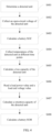
- FIG. 4 is a schematic flowchart of a method for detecting a battery state of health according to another embodiment of the present invention.
- specific content of S401 to S403 is similar to that of S301 to S303 in the foregoing embodiment, and describes determining of a detected unit by the CPU module 201 and how to obtain a battery SOC value by means of calculation.
- Specific content of S404 and S405 is similar to that of S304 and S305 in the foregoing embodiment, and describes how the CPU module 201 obtains a loss capacity of the detected unit by means of calculation. Therefore, details are not described herein again.
- a difference between this embodiment and the foregoing embodiment is as follows: In S406, after obtaining the loss capacity of the detected unit by means of calculation, the CPU module 201 reads a prestored load power value and load end voltage value. In S407, the CPU module 201 obtains a retention capacity of the detected unit by means of calculation according to the load power value, the load end voltage value, and the loss capacity of the detected unit.
- a power value and an end voltage value that are required by the load 105 are usually prestored in the memory 206 or in the storage subunit of the CPU module 201.
- the CPU module 201 reads the prestored load power value and load end voltage value, and then calculates the retention capacity of the detected unit by using formula 8.
- Q r represents a retention capacity of the detected unit at a current detection time point
- Q nom represents an original capacity of the detected unit
- Q th represents a loss capacity of the detected unit that is between the current detection time point and a battery delivery time point
- W represents the load power
- U represents the load end voltage
- I th is a constant
- p is a Peukert coefficient.
- I th I th ⁇ C 25 .
- a value of C is equal to a discharging capacity value of the detected unit within one hour.
- I th may be set according to a service requirement, or may be set by a person skilled in the art according to experience.
- a specified constant may be prestored in the storage subunit of the CPU module 201, or may be prestored in the memory 206.
- the CPU module 201 obtains the battery SOC value according to S402 and S403, and the CPU module 201 searches for the prestored information about the correspondence according to f and the battery SOC value, and determines a value of p .
- Table 1 f 0 ⁇ f ⁇ 5% 5% ⁇ f ⁇ 10% 10% ⁇ f ⁇ 15% 15% ⁇ f ⁇ 20% SOC ⁇ 90% ⁇ 90% ⁇ 90% ⁇ 90% 290% ⁇ 90% ⁇ 90% ⁇ 90% p 0.03 0.01 0.035 0.02 0.04 0.02 0.05 0.025
- the CPU module 201 obtains a battery SOH value by means of calculation according to a ratio of the retention capacity of the detected unit to the original capacity of the detected unit.
- the CPU module 201 obtains the battery SOH value of the detected unit by means of calculation by using formula 9.
- SOH r represents the battery state of health
- Q nom represents the original capacity of the detected unit
- Q r represents the retention capacity of the detected unit at the current detection time point.
- the original capacity of the detected unit may be a capacity marked on a battery, or may be a capacity, determined by means of measurement, of a battery at delivery.
- a battery SOH for a battery that does not supply power to a load within a time period, a battery SOH can be detected without having the battery removed from a communications device in this embodiment of the present invention.
- a process of obtaining the battery SOH not only a means in which the sampling circuit collects temperatures for multiple times is used, but also a method in which a battery loss capacity corresponding to a temperature obtained in each time of sampling is obtained by means of calculation in a differential and recursive manner is used.
- impact of the load on a current when the battery supplies power to the load is further considered, and the Peukert coefficient and a requirement of the communications device on the load power and the load end voltage are introduced as calculation factors.
- W U I r
- I r represents a battery discharging current that is corresponding to the load power and that exists when the battery supplies power to the load.
- I th ⁇ C 25 I r is apparently greater than I th
- I th ⁇ U W I th I r , that is, a value obtained by dividing I th by I r is introduced in a calculation for obtaining the battery SOH value.
- a difference between this embodiment and the foregoing embodiment is as follows: For a special case, that is, a temperature of an environment in which the standby power source is located remains unchanged, the sampling circuit 202 needs to collect a temperature of a power source of the detected unit only once at a current detection time point, and does not need to collect temperatures at different time points. Correspondingly, when calculating a battery SOH value, the CPU module 201 no longer considers, as a factor, a variation relationship between a temperature obtained at a different time point and a battery loss capacity.
- the CPU module 201 sends control information for collecting a temperature to the sampling circuit 202.
- the sampling circuit 202 receives the control information from the CPU module 201, collects a temperature of the detected unit at a current detection time point, and outputs one temperature value of the detected unit to the CPU module 201.
- the CPU module 201 obtains a loss capacity of the detected unit by means of calculation according to the battery SOC value and the temperature value.
- the sampling circuit 202 collects a temperature T of the power source of the detected unit at 2015-10-01 9:00, and then outputs the detection time point and the temperature value to the CPU module 201.
- the CPU module 201 obtains the loss capacity of the detected unit.
- the loss capacity of the detected unit is calculated by using formula 10.
- t 0 represents a battery delivery time point
- t m represents a current detection time point
- ( t m - t 0 ) represents days between the current detection time point and the battery delivery time point
- Q loss represents a loss capacity of the detected unit that is between the current detection time point and the battery delivery time point
- exp(S+L / T) represents an exponential function in which a natural number e is a base, that is, e is raised to the power of ( S + L / T ), a value of e is 2.718282, S, L, and M are all constants
- T represents the temperature of the power source of the detected unit.
- a person skilled in the art presets information about a correspondence between the constants S, L, and M and a battery SOC, and prestores the information in the memory 206 or in the storage subunit of the CPU module 201.
- the CPU module 201 obtains the battery SOC value according to S502 and S503, and then searches for the prestored information about the correspondence, so as to determine values of the constants S, L, and M.
- a method for setting the constants S, L, and M is well known by a person skilled in the art, and details are not further described herein.
- Specific content of S506 is similar to that of S306 in the foregoing embodiment, that is, the CPU module 201 calculates a battery SOH value of the detected unit by using formula 7. Details are not described herein again.
- a temperature of an environment in which the standby power source is located remains unchanged, but also a current change generated due to the load to which the detected unit supplies power is considered.
- specific content of S601 to S603 is similar to that of S301 to S303 in the foregoing embodiment, and describes determining of a detected unit by the CPU module 201 and how to obtain a battery SOC value by means of calculation.
- Specific content of S604 and S605 is similar to that of S504 and S505 in the foregoing embodiment, and describes obtaining, by the CPU module 201, a loss capacity of the detected unit by means of calculation by using formula 10 and according only to one temperature value obtained at a current detection time point.
- Specific content of S606 and S607 is similar to that of S406 and S407 in the foregoing embodiment, and describes obtaining, by the CPU module 201, a retention capacity of the detected unit by means of calculation by using formula 8 and according to a prestored load power value and load end voltage value.
- Specific content of S608 is similar to that of S408 in the foregoing embodiment, and describes obtaining, by the CPU module 201, a battery SOH value by means of calculation by using formula 9. Partial content in this embodiment is described in detail in the foregoing multiple embodiments, and therefore, details are not described herein again.
- a battery SOH for a battery that does not supply power to a load within a time period, a battery SOH can be detected without having the battery removed from a communications device.
- a process of obtaining the battery SOH a special case of the temperature of the environment in which the standby power source is located is considered.
- impact of the load on a current when the battery supplies power to the load is further considered, and the Peukert coefficient and a requirement of the communications device on the load power and the load end voltage are introduced as calculation factors. Therefore, in this embodiment of the present invention, a deterioration degree of battery performance can be accurately monitored, impact on a service can be avoided while the battery SOH is detected, and a capability of supplying power to the load by an aged battery is accurately estimated.
- the subject matters described in this specification may be implemented by using a non-transitory computer readable medium that stores a computer executable instruction.
- the instruction controls the BMU 104 to perform steps.
- a computer readable medium applicable to implementation of the subject matters described in this specification includes the non-transitory computer readable medium, such as a magnetic disk storage device, a chip storage device, a programmable logical device, or an application-specific integrated circuit.
- the computer readable medium that implements the subject matters described in this specification may be located on a single device or computing platform, or may be distributed on multiple devices or computing platforms.
Landscapes
- Physics & Mathematics (AREA)
- General Physics & Mathematics (AREA)
- Secondary Cells (AREA)
- Charge And Discharge Circuits For Batteries Or The Like (AREA)
- Tests Of Electric Status Of Batteries (AREA)
Description
- This application mainly relates to technologies for detecting a battery state of health, and in particular, to an apparatus and a method for estimating a deterioration degree of battery performance for a battery that does not supply power to a load within a time period.
- As an electric energy storage apparatus, a battery has significant applications in many fields. In an application field of stationary energy storage, a standby power source is usually installed in a communications device such as a data center device, an optical transmission device, or a base station. The standby power source may be a single battery, or may be a battery group including multiple batteries connected in parallel or in series. Usually, if a battery of the standby power source does not supply power to a load within a time period, natural deterioration inevitably occurs in battery performance. Therefore, to ensure that the standby power source can supply a sufficient electricity quantity to the communications device, a user imposes a relatively high requirement on a state of health (SOH) of the battery of the standby power source.
- In some existing application fields, although a battery internal resistance is related to a battery capacity, an increase in the battery internal resistance does not necessarily cause a loss of the battery capacity. Comparatively, in most application fields, a battery retention capacity is usually used as a parameter indicator for measuring a battery SOH, and can accurately represent battery capacity information.
- For the battery of the standby power source in the communications device, a battery retention capacity parameter cannot be obtained by detecting a load voltage and a load current. Therefore, in the prior art, the battery retention capacity parameter is usually obtained by means of test by using a method in which the battery is fully charged or fully discharged. However, the battery needs to be removed before being fully charged or fully discharged. That is, the battery needs to be removed from the communications device of the battery. If an active power source of the communications device stops supplying power, when the battery of the standby power source is exactly removed and is in a discharging or charging state, the standby power source cannot ensure normal working of the communications device, and this greatly affects a service.
- LONG LAM ET AL: "Practical Capacity Fading Model for Li-Ion Battery Cells in Electric Vehicles", IEEE TRANSACTIONS ON POWER ELECTRONICS, INSTITUTE OF ELECTRICAL AND ELECTRONICS ENGINEERS, USA, vol. 28, no. 12, 1 December 2013 (2013-12-01), pages 5910 - 5918, XP011514321 discloses a model for Li-ion cells based on operating conditions in electric vehicles.
-
EP2023154A2 discloses a battery status detecting method for detecting a battery status of a secondary battery that supplies power to an electrical load, the method comprises: a current measuring step of measuring a discharge current value of the secondary battery; and an estimating step of estimating a dischargeable capacity or a dischargeable time of the secondary battery with the measured discharge current value based on discharge characteristics of the secondary battery indicating a discharge status of the secondary battery when a voltage of the secondary battery drops to a predetermined voltage specified by the electrical load. -
WO2015141500A1 discloses a degradation estimation method. In this degradation estimation method, a stopping time of a battery control device configured so as to be capable of calculating the charge state of a battery is detected; degradation information corresponding to a calculated charge state calculated from the battery and a detection temperature detected from the battery or degradation information corresponding to the calculated charge state and the ambient temperature is acquired on the basis of a first degradation information database indicating battery degradation corresponding to a set charging state and set temperature; and the degradation of the battery at the stopping time is estimated on the basis of the acquired degradation information. - This application provides an apparatus for detecting a battery state of health, so as to detect a battery state of health for a battery that does not supply power to a load within a time period, and accurately monitor a deterioration degree of battery performance.
- According to a first aspect, this application provides an apparatus for detecting a battery state of health, and the apparatus includes a CPU module and a sampling circuit. The CPU module is configured to: determine a detected unit, and send control information to the sampling circuit. The detected unit includes at least one battery, and the at least one battery does not supply power to a load within a time period before the at least one battery is detected. The sampling circuit is configured to: receive the control information from the CPU module, collect an open-circuit voltage and a temperature of the detected unit, and output the obtained open-circuit voltage value and temperature value to the CPU module. The CPU module is further configured to: perform calculation according to the open-circuit voltage value received from the sampling circuit, to obtain a battery state of charge value of the detected unit; perform calculation according to the battery state of charge value and the temperature value, to obtain a loss capacity of the detected unit; and perform calculation according to a ratio of the loss capacity of the detected unit to an original capacity, to obtain a battery state of health value of the detected unit; the sampling circuit (202) is specifically configured to: collect temperatures of the detected unit at multiple different detection time points, and output the temperature values obtained at different detection time points to the CPU module; and the CPU module (201) is specifically configured to perform calculation according to the battery state of charge value and the temperature values obtained at different detection time points, to obtain the loss capacity of the detected unit.
- With reference to the first aspect, the sampling circuit is specifically configured to: collect temperatures of the detected unit at multiple different detection time points, and output the temperature values obtained at different detection time points to the CPU module. The CPU module is specifically configured to perform calculation according to the battery state of charge value and the temperature values obtained at different detection time points, to obtain the loss capacity of the detected unit. Specifically, the CPU module calculates, by using the following two formulas, first parameters corresponding to the battery state of charge value and the temperature values obtained at different detection time points, and second parameters corresponding to the temperature values obtained at different detection time points:


- In the formulas, k represents the first parameter, T represents the temperature of the detected unit, SOC represents the battery state of charge, and x 1, x 2, y 1, y 2, c, and d are preset constants; and α represents the second parameter, T represents a temperature of a power source of the detected unit, exp(λ/T) represents an exponential function in which a natural number e is raised to the power of (λ/T), a value of e is 2.718282, and x 0 and λ are preset constants. In this implementation, a case in which a temperature of a battery varies with time is considered, and a parameter corresponding to a temperature is calculated according to temperatures collected by the sampling circuit for multiple times, so that the finally obtained battery state of health value is more accurate.
- After the CPU module obtains the first parameters and the second parameters, with reference to the foregoing possible implementation, in a possible implementation, the CPU module performs a differential operation according to the first parameters and the second parameters for the temperatures obtained at different detection time points, to obtain a loss capacity that is of the detected unit and is corresponding to a temperature obtained at each detection time point:

- In the differential expression, dQloss represents a loss capacity of the detected unit that is between a current detection time point and a previous detection time point, k represents the first parameter, α represents the second parameter, Qloss (t) represents a loss capacity that is of the detected unit and is corresponding to a detection time point t, and Qnom represents the original capacity of the detected unit. In this implementation, in consideration that the detected unit does not supply power to the load, and that the detected unit is actually discharged gradually in a form of a small current, a battery loss capacity corresponding to a temperature obtained in each time of sampling is obtained by means of calculation in a differential and recursive manner, so that the finally obtained battery state of health value is more accurate.
- With reference to the first aspect, or the foregoing multiple possible implementations, in a possible implementation, the CPU module collects a temperature of the detected unit only at one detection time point, and calculates the loss capacity of the detected unit by using the following formula:

- In the formula, t0 represents a battery delivery time point, tm represents a current detection time point, (tm - t0 ) represents days between the current detection time point and the battery delivery time point, Qloss represents a loss capacity of the detected unit that is between the current detection time point and the battery delivery time point, exp(S+L/T) represents an exponential function in which a natural number e is raised to the power of (S+L/T), a value of e is 2.718282, S, L, and M are all constants, and T represents the temperature of the detected unit.
- Based on the foregoing content, in this application, for a battery that does not supply power to a load within a time period, an open-circuit voltage and a temperature of the battery are collected without having the battery removed from a communications device. A battery loss capacity is determined by using the open-circuit voltage value and the temperature value of the battery and a battery state of charge value obtained by means of calculation. In this way, a battery state of health is accurately detected, and impact on a service is avoided.
- After the drawings and detailed descriptions in the following are researched, another system, method, feature, and advantage become obvious for a person of ordinary skill in the art.
-
-
FIG. 1 is a schematic structural diagram of a base station according to an embodiment of the present invention; -
FIG. 2 is a schematic structural diagram of an apparatus for detecting a battery state of health according to an embodiment of the present invention; -
FIG. 3 is a schematic flowchart of a method for detecting a battery state of health according to an embodiment of the present invention; and -
FIG. 4 is a schematic flowchart of a method for detecting a battery state of health according to another embodiment of the present invention. - In all the drawings, a same reference symbol or description represents components that are similar but not necessarily the same. Examples of embodiments described in this specification are easily modified in various manners or replaced in another form. Therefore, specific embodiments are already illustrated by using examples in the accompanying drawings and are described in detail in this specification. However, the examples of the embodiments described in this specification are not intended to limit the disclosed specific form. Instead, the present invention covers all modifications, equivalence, and replacements that fall within the scope of the appended claims.
- The following explains and describes some technical terms throughout this specification, to help understand this application.
- A battery SOH represents a battery state of health, and is a ratio of a capacity of a battery that is fully charged after the battery is aged, to an original capacity of the battery at delivery.
- A battery retention capacity is a capacity of a battery that is fully charged after the battery is aged.
- Battery aging indicates that battery performance deteriorates if a battery does not supply power to a load within a time period.
- An open-circuit voltage (OCV) is an end voltage of a battery in an open-circuit state.
- A battery SOC (state of charge) represents a battery state of charge, and is a ratio of a remaining capacity of a battery to a capacity of the battery in a fully charged state.
- Embodiments in this specification provide various technical solutions, so that a battery state of health can be detected for a battery that does not supply power to a load within a time period.
- To make the objectives, technical solutions, and advantages of this application more understandable, the following provides detailed descriptions. The detailed descriptions provide various embodiments of a device and/or a process by using block diagrams, flowcharts, and/or examples. These block diagrams, flowcharts, and/or examples include one or more functions and/or operations. Therefore, a person in the art may understand that each function and/or operation in the block diagrams, the flowcharts, and/or the examples may be performed independently and/or jointly by using much hardware, software, and firmware, and/or any combination thereof.
- Generally, a communications device includes a central controller, an active power source, a standby power source, an apparatus for detecting a battery state of health, and a load. The central controller is configured to: control the active power source or the standby power source to output a corresponding voltage and current according to a need of the load, and control the active power source to charge the standby power source. The active power source and the standby power source are configured to provide a reliable voltage and current for the load in the communications device, to ensure that a service is not interrupted. According to a use need of the communications device, the active power source may include one power supply unit (Power Supply Unit, PSU) or multiple PSUs connected in parallel. The PSU is configured to convert an external alternating current into a direct current for use by the load. Alternatively, the active power source may include one solar supply unit (Solar Supply Unit, SSU) or multiple SSUs connected in parallel. The SSU is configured to convert a direct current from a photovoltaic panel into a direct current for use by the load. A voltage of the direct current from the photovoltaic panel is relatively large, and is usually greater than 100 V. A load in a communications device such as a base station usually uses a direct current whose voltage is 48 V. Alternatively, the active power source may include a PSU and an SSU that are connected in parallel.
- There may be one or more standby power sources. The standby power source may include one battery or multiple batteries connected in series/parallel. The standby power source usually does not supply power to the load in the communications device. The apparatus for detecting a battery state of health may be referred to as a battery management unit (BMU), or may be referred to as a battery management system (battery manage system, BMS). The apparatus for detecting a battery state of health has different names in different application fields. The BMS and the BMU are only examples, and are not intended to limit this application. The apparatus for detecting a battery state of health is configured to detect a deterioration degree of battery performance in the standby power source. Optionally, a quantity of apparatuses for detecting a battery state of health is related to a quantity of batteries in the standby power source. If there is a relatively large quantity of batteries, a specific quantity of apparatuses for detecting a battery state of health are configured. A type of the battery in the standby power source is not specifically limited, and the type of the battery may include a lithium-ion battery, a lithium polymer battery, a Ni-Cd battery, a NiMH battery, a NiZn battery, and the like.
- According to different communications devices, the load is presented in multiple forms. For example, the load may be a high-speed computing processor of a data center device, a baseband radio frequency processing unit of a base station, or a main control board of a fiber optic communications device. The load in this application is not specifically limited.
- For example, the communications device is a base station.
FIG. 1 is a schematic structural diagram of abase station 100 according to an embodiment of the present invention. Referring toFIG. 1 , thebase station 100 includes acentral controller 101, an active power source, a standby power source, twoBMUs 104, and aload 105. Thecentral controller 101 is connected to each of the active power source, the standby power source, theBMUs 104, and theload 105 by using a power bus (shown by a thick solid line inFIG. 1 ). The active power source includes twoPSUs 102 and twoSSUs 103 that are connected in parallel. The standby power source includes multiple batteries connected in series. Thecentral controller 101 is connected to each of the active power source, the standby power source, theBMUs 104, and theload 105 by using a communications bus (shown by a thin solid line inFIG. 1 ); controls thePSUs 102 and theSSUs 103 to provide a reliable voltage and current for theload 105; controls thePSUs 102 and theSSUs 103 to charge the standby power source; and controls theload 105 to execute a communication service. When thePSUs 102 and theSSUs 103 stop supplying power, the standby power source provides a reliable voltage and current for theload 105, to ensure that the communication service is not interrupted. In this embodiment, a quantity of PSUs, a quantity of SSUs, and a quantity of batteries are only examples, and are not intended to limit this application. -
FIG. 2 is a schematic structural diagram of an apparatus for detecting a battery state of health according to an embodiment of the present invention. The apparatus for detecting a battery state of health may be referred to as a BMU. With reference toFIG. 1, FIG. 2 further shows an inner composition structure of theBMU 104. Referring toFIG. 2 , theBMU 104 includes aCPU module 201 and asampling circuit 202. The apparatus may further include apower source module 203, acommunications module 204, acontrol circuit 205, amemory 206, and adisplay 207. - As shown in
FIG. 2 , theCPU module 201, thesampling circuit 202, thecommunications module 204, thecontrol circuit 205, thememory 206, and thedisplay 207 are connected to each other by using a data bus (shown by a thin solid line inFIG. 2 ). TheCPU module 201 is configured to: determine a detected unit, and send control information to thesampling circuit 202. The detected unit includes one or more batteries that do not supply power to the load. For example, if the standby power source is a single battery, the single battery may be used as the detected unit. For example, if the standby power source is a battery group including multiple batteries connected in parallel, the battery group may be used as the detected unit. For example, if the standby power source is a battery group including multiple batteries connected in series, the battery group may be used as the detected unit, or one battery in the battery group may be used as a detected unit, or a battery group including multiple adjacent batteries connected in series in the battery group is used as a detected unit. According to actual composition of the standby power source, with reference to a service requirement, the detected unit may be automatically set by using a preset rule. Alternatively, the detected unit may be set by a person skilled in the art according to experience. - The
sampling circuit 202 receives the control information from theCPU module 201, collects an open-circuit voltage of the detected unit, and outputs the collected voltage value to theCPU module 201. Next, theCPU module 201 stores the voltage value in a storage subunit (not shown in the figure) built in theCPU module 201, or theCPU module 201 stores the voltage value in thememory 206. An open-circuit voltage of a battery is an end voltage of the battery in an open-circuit state. The collected open-circuit voltage correspondingly varies with the detected unit. For example, if the detected unit is one battery, voltages at both ends of the battery in the open-circuit state are open-circuit voltages. For example, if the detected unit is a battery group including multiple batteries connected in parallel or in series, voltages at both ends of the battery group in the open-circuit state are open-circuit voltages. Thesampling circuit 202 is further configured to: receive the control information from theCPU module 201, collect a temperature of the detected unit, and output the collected temperature value to theCPU module 201. Next, theCPU module 201 stores the temperature value, or theCPU module 201 stores the temperature value in thememory 206. The sampling circuit is further configured to: collect a current electricity quantity state information of the standby power source, and output the electricity quantity state information to theCPU module 201. - The
CPU module 201 is further configured to receive information collected by thesampling circuit 202, for example, a battery open-circuit voltage value, a battery current value, a battery level value, or a battery temperature value. TheCPU module 201 is further configured to: read various types of information stored in thememory 206, and perform corresponding computing and processing according to a pre-configured algorithm rule. - The
power source module 203 is connected to theCPU module 201, thesampling circuit 202, thecommunications module 204, thecontrol circuit 205, thememory 206, and thedisplay 207 by using a power bus (shown by a thick solid line inFIG. 2 ). Thepower source module 203 is configured to complete DC/DC conversion, that is, convert a direct current voltage required by the load into a direct current voltage required by theBMU 104. For example, theBMU 104 is installed in thebase station 100. A voltage provided by a power source of thebase station 100 for theload 105 is 48 v, and components of theBMU 104 require different voltages. For example, a voltage required by theCPU module 201 is 3.3 v, a voltage required by thesampling circuit 202 is 5 v, a voltage required by the communications module is 3.3 v, a voltage required by thecontrol circuit 205 is 12 v, a voltage required by thememory 206 is 3.3 v, and a voltage required by thedisplay 207 is 3.3 V. In this case, thepower source module 203 converts the input voltage of 48 V into the power source voltages required by the components, and outputs the voltages. - The
communications module 204 is configured to receive or send information exchanged between thecentral controller 101 and theBMU 104. When a battery electricity quantity of the standby power source is relatively low, theCPU module 201 sends electricity quantity state information of the standby power source to thecommunications module 204. Thecommunications module 204 reports the electricity quantity state information to thecentral controller 101. Next, thecentral controller 101 sends control information for charging the standby power source to thecommunications module 204, and thecommunications module 204 transfers the control information to theCPU module 201. Thecontrol circuit 205 is connected to a power switch of the standby power source. TheCPU module 201 triggers, according to the control information, thecontrol circuit 205 to switch on the power switch of the standby power source, to close a power line loop between the active power source and the standby power source, so that the battery in the standby power source can obtain an electricity quantity supplement provided by the active power source. - The
memory 206 may be a well-known semiconductor component that can record and from which data can be deleted, for example, a RAM, a ROM, an EEPROM, or a mass storage medium such as a hard disk. - The
display 207 is configured to output the electricity quantity state information, battery state of health information, and the like of the battery in the standby power source that are obtained by theCPU module 201. Thedisplay 207 may use any apparatus that displays the information visually. For example, a display apparatus may be an LCD display or an LED display. - To accurately obtain a battery SOH of the detected unit in the standby power source, multiple factors further need to be considered after state of charge information of the detected unit is obtained. In an embodiment of the present invention, because a temperature of a power source of the detected unit varies with time, when calculating the battery SOH value, the apparatus (which may be referred to as a BMU) for detecting a battery state of health needs to consider a relationship between a temperature obtained at a different time point and a battery state of charge, and consider a relationship between a temperature obtained at a different time point and a battery loss capacity. As shown in
FIG. 3, FIG. 3 is a schematic flowchart of a method for detecting a battery state of health according to an embodiment of the present invention. With reference to thebase station 100 described inFIG. 1 and theBMU 104 described inFIG. 2 , the following specifically describes how theBMU 104 obtains the battery SOH value by means of calculation. - In S301, the
CPU module 201 determines a detected unit, and sends, to thesampling circuit 202, control information for collecting an open-circuit voltage. In S302, thesampling circuit 202 receives the control information from theCPU module 201, collects an open-circuit voltage of the detected unit, and outputs the open-circuit voltage value of the detected unit to theCPU module 201. In S303, theCPU module 201 obtains a battery SOC value by means of calculation according to the open-circuit voltage value of the detected unit. - There are multiple implementations in which the
CPU module 201 obtains the battery SOC. For example, the battery SOC value is calculated by using a formula. A correspondence between an open-circuit voltage and a battery SOC may be represented by using the following formula 1:
- In formula 1, OCV represents the open-circuit voltage, SOC represents the battery state of charge, and n, a 1, a 2, an , and b are constants. Theses constants may be set according to a service requirement, or may be set by a person skilled in the art according to experience, and n is a positive integer. Because the setting manner belongs to the prior art well known by a person skilled in the art, details are not further described herein. A specified constant may be prestored in the storage subunit of the
CPU module 201, or may be prestored in thememory 206. - With reference to formula 1, for example, if a value of n is 7, an expression for the correspondence between an open-circuit voltage and a battery state of charge may be as follows:
OCV=-89.6*(SOC) 7 +320*(SOC)6 -447.7*(SOC)5 +307.7*(SOC)4 -10 5.2*(SOC)3 +15.3*(SOC)2 +0.3444*(SOC) +3.31. - For another example, before the battery of the standby power source is installed in the communications device, a person skilled in the art obtains information about a correspondence between an open-circuit voltage and a battery SOC by performing multiple times of experiments and tests; and then prestores the information about the correspondence in the
memory 206, or prestores the information about the correspondence in the storage subunit of theCPU module 201. Because the experiment and test means belongs to the prior art well known by a person skilled in the art, details are not further described herein. TheCPU module 201 receives the open-circuit voltage value of the detected unit, and obtains the battery SOC value by reading the prestored information about the correspondence between an open-circuit voltage and a battery SOC. - In S304, the
CPU module 201 sends control information for collecting a temperature to thesampling circuit 202. Thesampling circuit 202 receives the control information from theCPU module 201; collects temperatures of the detected unit at different detection time points; and outputs, to theCPU module 201, the temperature values of the detected unit that are obtained at different detection time points. In S305, theCPU module 201 obtains a loss capacity of the detected unit by means of calculation according to the battery SOC value and the temperature values obtained at different detection time points. - Specifically, the
sampling circuit 202 collects a temperature of the power source of the detected unit at a first time point (for example, 2015-07-01 9:00), and then outputs a first temperature value of the detected unit to theCPU module 201. For example, if the power source is a single battery, a temperature of the single battery is the collected temperature. For example, if the power source is a battery group including multiple batteries connected in parallel or in series, a temperature of the battery group is the collected temperature. - The
CPU module 201 receives the first temperature value of the power source of the detected unit that is obtained at the first time point; and obtains, according to the first temperature value and the battery SOC value, a first parameter and a second parameter that are corresponding to the first temperature value. There are multiple implementations in which theCPU module 201 obtains the first parameter and the second parameter. For example, the first parameter and the second parameter are calculated by using formulas. Specifically: 1) a correspondence between a first parameter and both a temperature of the detected unit and a battery SOC may be represented by using the following formula 2:
- In formula 2, k represents the first parameter, T represents the temperature of the power source of the detected unit, SOC represents the battery state of charge, and x 1, x 2, y 1, y 2, c, and d are constants. These constants may be set according to a service requirement, or may be set by a person skilled in the art according to experience. Because the setting manner belongs to the prior art well known by a person skilled in the art, details are not further described herein. A specified constant may be prestored in the storage subunit of the
CPU module 201, or may be prestored in thememory 206. - With reference to formula 2, for example, an expression for the correspondence between k and both a temperature and a battery state of charge may be as follows:
k =-0.0015*T +0.0000025*T 2 +0.027*SOC2 +0.000045*T *SOC +0.21. - 2) A correspondence between a second parameter and a temperature of the detected unit may be represented by using the following formula 3:

- In formula 3, α represents the second parameter, T represents the temperature of the power source of the detected unit, exp(λ/T) represents an exponential function in which a natural number e is a base, that is, e is raised to the power of (λ/T), a value of e is 2.718282, and x 0 and λ are constants. These constants may be set according to a service requirement, or may be set by a person skilled in the art according to experience. Because the setting manner belongs to the prior art well known by a person skilled in the art, details are not further described herein. A specified constant may be prestored in the storage subunit of the
CPU module 201, or may be prestored in thememory 206. - With reference to formula 3, for example, an expression for the correspondence between α and T may be as follows:

- For another example, before the battery of the standby power source is installed in the communications device, a person skilled in the art obtains information about a correspondence between a first parameter and both a temperature of the detected unit and a battery SOC, and information about a correspondence between a second parameter and a temperature of the detected unit by performing multiple times of experiments and tests; and then prestores the two pieces of information about the two correspondences in the
memory 206, or in the storage subunit of theCPU module 201. Because the experiment and test means belongs to the prior art well known by a person skilled in the art, details are not further described herein. TheCPU module 201 receives the first temperature value; obtains, by reading the prestored information about the correspondence between a first parameter and both a temperature of the detected unit and a battery SOC, the first parameter corresponding to the first temperature value; and obtains, by reading the prestored information about the correspondence between a second parameter and a temperature of the detected unit, the second parameter corresponding to the first temperature value. - The
CPU module 201 obtains, according to the first parameter and the second parameter that are corresponding to the first temperature value, a loss capacity that is of the detected unit and is corresponding to the first temperature value. There are multiple implementations in which theCPU module 201 obtains the loss capacity of the detected unit. For example, the loss capacity of the detected unit is calculated by using a formula. Specifically, a correspondence between a loss capacity of the detected unit and both a first parameter and a second parameter may be represented by using the following formula 4:
- In formula 4, t 0 represents a battery delivery time point, tm represents a current detection time point, (tm - t0 ) represents days between the current detection time point and the battery delivery time point, Qloss represents a loss capacity of the detected unit that is between the current detection time point and the battery delivery time point, Qnom represents an original capacity of the detected unit, k represents the first parameter, and α represents the second parameter. With reference to this embodiment of the present invention, for example, the battery delivery time point is 2015-06-01 9:00, and the first time point is used as the current detection time point tm . For example, tm is 2015-07-01 9:00.
- Because the temperature of the power source of the detected unit varies with time, k and α correspondingly change. In this case, the
CPU module 201 needs to obtain, by means of calculation in a differential manner and based on the loss capacity that is of the detected unit and is corresponding to the first temperature, a loss capacity that is of the detected unit and is corresponding to a temperature to be collected at a next detection time point. A corresponding differential expression is as follows: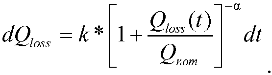
- In the differential expression, dQloss represents a loss capacity of the detected unit that is between a current detection time point and a previous detection time point, k represents the first parameter, and α represents the second parameter. Because differential processing is performed on a basis of time, k and α are separately corresponding to the current time point. Qloss (t) represents a loss capacity that is of the detected unit and is corresponding to a time point t, and Qnom represents the original capacity of the detected unit. In the calculation method, multiple times of temperature sampling are performed, and a loss capacity that is of the detected unit and is corresponding to a temperature obtained in each time of sampling is obtained by means of calculation in a recursive manner and based on each sampling time point. For example, if the
sampling circuit 202 collects temperatures T 1 and T 2 of the power source of the detected unit at two time points, after obtaining a loss capacity that is of the detected unit and is corresponding to T 1, theCPU module 201 further needs to obtain, by means of calculation based on a time difference between the two time points, a loss capacity that is of the detected unit and is corresponding to T 2 . For another example, if thesampling circuit 202 collects temperatures T 1, T 2, and T 3 of the power source of the detected unit at three time points, after obtaining a loss capacity that is of the detected unit and is corresponding to T 1, theCPU module 201 first obtains, by means of calculation based on a time difference (T 2-T 1) between the first two time points, a loss capacity that is of the detected unit and is corresponding to T 2; and then obtains, by means of calculation based on a time difference (T 3-T 2) between the last two time points, a loss capacity that is of the detected unit and is corresponding to T 3. A quantity of temperature sampling times is not limited in the foregoing examples. By analogy, other cases are similar. Details are not further described herein. - A further description is given by using an example that the
sampling circuit 202 collects temperatures of the power source of the detected unit at two time points. Based on the foregoing description, thesampling circuit 202 obtains a first temperature of the detected unit by means of collection. Next, thesampling circuit 202 collects a second temperature of the detected unit at a second time point, and then outputs the first temperature value and the second temperature value to theCPU module 201. A difference between the second time point and a first time point is usually not greater than 0.5 day. For example, if the second time point is 2015-07-01 15:00, and the first time point is 2015-07-01 9:00, a difference between 2015-07-01 15:00 and 2015-07-01 9:00 is 0.25 day. TheCPU module 201 receives the second temperature value, and obtains, according to the second temperature value and the battery SOC value, a first parameter and a second parameter that are corresponding to the second temperature. With reference to the foregoing description, theCPU module 201 may obtain, by using formula 2 and formula 3, the first parameter and the second parameter that are corresponding to the second temperature; or may obtain, by reading prestored correspondence information, the first parameter and the second parameter that are corresponding to the second temperature. A detailed calculation process is not described herein. - The
CPU module 201 obtains, by means of calculation by using formula 5 and according to a loss capacity that is of the detected unit and is corresponding to the first temperature and the first parameter and the second parameter that are corresponding to the second temperature, a loss capacity that is of the detected unit and is corresponding to the second temperature. Formula 5 is as follows:
- In formula 5, tn represents a previous detection time point, tm represents a current detection time point, (tm - tn ) represents days between the current detection time point and the previous detection time point, and usually, (tm - tn ) ≤0.5, ΔQloss represents a loss capacity of the detected unit that is between the current detection time point and the previous detection time point, Qloss_n represents a loss capacity that is of the detected unit and is corresponding to a temperature collected at the time point tn , k represents the first parameter, and α represents the second parameter. With reference to this embodiment of the present invention, the first time point is used as tn (for example, 2015-07-01 9:00), the second time point is used as tm (for example, 2015-07-01 15:00), days between the second time point and the first time point are used as (tm - tn ) (for example, the difference between 2015-07-01 15:00 and 2015-07-01 9:00 is 0.25 day), a loss capacity of the detected unit that is between the second time point and the first time point is used as ΔQloss , and the loss capacity that is of the detected unit and is corresponding to the first temperature is used as Qloss_n .
- The
CPU module 201 calculates, by using formula 6 and according to the loss capacity that is of the detected unit and is corresponding to the first temperature and the loss capacity that is of the detected unit and is corresponding to the second temperature, a loss capacity of the detected unit that is between a current detection time point and a battery delivery time point. Formula 6 is as follows:
- In formula 6, Qth represents the loss capacity of the detected unit that is between the current detection time point and the battery delivery time point, Qloss represents a loss capacity of the detected unit that is between the first detection time point and the battery delivery time point, and ΔQloss represents a loss capacity of the detected unit that is between the current detection time point and a previous detection time point. With reference to this embodiment of the present invention, the second time point is used as the current detection time point, the first time point is used as the first detection time point, and the difference between the second time point and the first time point is used as the difference between the current detection time point and the previous detection time point. It should be noted that if the
sampling circuit 202 collects temperatures of the power source of the detected unit at at least N (N≥3, and N is a positive integer) time points, theCPU module 201 obtains Qth by means of calculation according to accumulated (N-1) ΔQloss in a recursive manner. - In S306, the
CPU module 201 obtains a battery SOH value by means of calculation according to a ratio of the loss capacity of the detected unit to the original capacity of the detected unit. - Usually, the original capacity of the detected unit may be a capacity marked on a battery, or may be an original capacity, determined by means of measurement, of a battery at delivery. The
CPU module 201 obtains the battery SOH value of the detected unit by means of calculation by using formula 7. Formula 7 is as follows:
- In formula 7, SOHth represents the battery state of health of the detected unit, Qnom represents the original capacity of the detected unit, Qth represents the loss capacity of the detected unit that is between the current detection time point and the battery delivery time point.
- In this embodiment of the present invention, for a battery that does not supply power to a load within a time period, a battery SOH can be detected without having the battery removed from a communications device. In a process of obtaining the battery SOH, a means in which the sampling circuit collects temperatures for multiple times is used, and this represents consideration of a factor that a temperature of the battery varies with time. In addition, during calculation, in consideration that the detected unit does not supply power to the load, and that the detected unit is actually discharged gradually in a form of a small current, a battery loss capacity corresponding to a temperature obtained in each time of sampling is obtained by means of calculation in a differential and recursive manner, so that Qth is obtained. A value of Qth is equivalent to a capacity obtained by fully charging or fully discharging the detected unit by using a current Ith,

- Optionally, in another embodiment of the present invention, to accurately obtain a battery SOH of the detected unit in the standby power source, after state of charge information of the detected unit is obtained, it is necessary to consider not only a factor that a temperature of a power source of the detected unit varies with time, but also a current change generated due to the load to which the detected unit supplies power. As shown in
FIG. 4, FIG. 4 is a schematic flowchart of a method for detecting a battery state of health according to another embodiment of the present invention. In this embodiment, specific content of S401 to S403 is similar to that of S301 to S303 in the foregoing embodiment, and describes determining of a detected unit by theCPU module 201 and how to obtain a battery SOC value by means of calculation. Specific content of S404 and S405 is similar to that of S304 and S305 in the foregoing embodiment, and describes how theCPU module 201 obtains a loss capacity of the detected unit by means of calculation. Therefore, details are not described herein again. A difference between this embodiment and the foregoing embodiment is as follows: In S406, after obtaining the loss capacity of the detected unit by means of calculation, theCPU module 201 reads a prestored load power value and load end voltage value. In S407, theCPU module 201 obtains a retention capacity of the detected unit by means of calculation according to the load power value, the load end voltage value, and the loss capacity of the detected unit. - Specifically, for the
base station 100, a power value and an end voltage value that are required by theload 105 are usually prestored in thememory 206 or in the storage subunit of theCPU module 201. TheCPU module 201 reads the prestored load power value and load end voltage value, and then calculates the retention capacity of the detected unit by using formula 8. Formula 8 is as follows:
- In formula 8, Qr represents a retention capacity of the detected unit at a current detection time point, Qnom represents an original capacity of the detected unit, Qth represents a loss capacity of the detected unit that is between the current detection time point and a battery delivery time point, W represents the load power, U represents the load end voltage, Ith is a constant, and p is a Peukert coefficient. For the constant Ith ,

CPU module 201, or may be prestored in thememory 206. For p, a person skilled in the art presets information about a correspondence between p and both battery aging degree f and a battery SOC according to experience, and stores the information in thememory 206 or in the storage subunit of theCPU module 201. For example, refer to the following table 1 for a case of a value, and
CPU module 201 obtains Qth according to S404 and S405, and can further obtain f by means of calculation. In addition, theCPU module 201 obtains the battery SOC value according to S402 and S403, and theCPU module 201 searches for the prestored information about the correspondence according to f and the battery SOC value, and determines a value ofp.Table 1 f 0≤f<5% 5%≤f<10% 10%≤f<15% 15%≤f<20% SOC ≥90% <90% ≥90% <90% 290% <90% ≥90% <90% p 0.03 0.01 0.035 0.02 0.04 0.02 0.05 0.025 - In S408, the
CPU module 201 obtains a battery SOH value by means of calculation according to a ratio of the retention capacity of the detected unit to the original capacity of the detected unit. - The
CPU module 201 obtains the battery SOH value of the detected unit by means of calculation by using formula 9. Formula 9 is as follows:
- In formula 9, SOHr represents the battery state of health, Qnom represents the original capacity of the detected unit, and Qr represents the retention capacity of the detected unit at the current detection time point. For Qnom in formula 8 and formula 9, generally, the original capacity of the detected unit may be a capacity marked on a battery, or may be a capacity, determined by means of measurement, of a battery at delivery.
- In this embodiment of the present invention, for a battery that does not supply power to a load within a time period, a battery SOH can be detected without having the battery removed from a communications device in this embodiment of the present invention. In a process of obtaining the battery SOH, not only a means in which the sampling circuit collects temperatures for multiple times is used, but also a method in which a battery loss capacity corresponding to a temperature obtained in each time of sampling is obtained by means of calculation in a differential and recursive manner is used. In addition, impact of the load on a current when the battery supplies power to the load is further considered, and the Peukert coefficient and a requirement of the communications device on the load power and the load end voltage are introduced as calculation factors. Specifically,


- Optionally, in another embodiment of the present invention, a difference between this embodiment and the foregoing embodiment is as follows: For a special case, that is, a temperature of an environment in which the standby power source is located remains unchanged, the
sampling circuit 202 needs to collect a temperature of a power source of the detected unit only once at a current detection time point, and does not need to collect temperatures at different time points. Correspondingly, when calculating a battery SOH value, theCPU module 201 no longer considers, as a factor, a variation relationship between a temperature obtained at a different time point and a battery loss capacity. In this embodiment, specific content of S501 to S503 is similar to that of S301 to S303 in the foregoing embodiment, and describes determining of a detected unit by theCPU module 201 and how to obtain a battery SOC value by means of calculation. Details are not described herein again. - In S504, the
CPU module 201 sends control information for collecting a temperature to thesampling circuit 202. Thesampling circuit 202 receives the control information from theCPU module 201, collects a temperature of the detected unit at a current detection time point, and outputs one temperature value of the detected unit to theCPU module 201. In S505, theCPU module 201 obtains a loss capacity of the detected unit by means of calculation according to the battery SOC value and the temperature value. - Specifically, for example, the
sampling circuit 202 collects a temperature T of the power source of the detected unit at 2015-10-01 9:00, and then outputs the detection time point and the temperature value to theCPU module 201. There are multiple implementations in which theCPU module 201 obtains the loss capacity of the detected unit. For example, the loss capacity of the detected unit is calculated by using formula 10. Formula 10 is as follows:
- In formula 10, t 0 represents a battery delivery time point, tm represents a current detection time point, (tm - t 0) represents days between the current detection time point and the battery delivery time point, Qloss represents a loss capacity of the detected unit that is between the current detection time point and the battery delivery time point, exp(S+L/T) represents an exponential function in which a natural number e is a base, that is, e is raised to the power of (S+L/T), a value of e is 2.718282, S, L, and M are all constants, and T represents the temperature of the power source of the detected unit. For these constants S, L, and M, a person skilled in the art presets information about a correspondence between the constants S, L, and M and a battery SOC, and prestores the information in the
memory 206 or in the storage subunit of theCPU module 201. TheCPU module 201 obtains the battery SOC value according to S502 and S503, and then searches for the prestored information about the correspondence, so as to determine values of the constants S, L, and M. A method for setting the constants S, L, and M is well known by a person skilled in the art, and details are not further described herein. - Specific content of S506 is similar to that of S306 in the foregoing embodiment, that is, the
CPU module 201 calculates a battery SOH value of the detected unit by using formula 7. Details are not described herein again. - Optionally, in another embodiment of the present invention, not only a special case is considered, that is, a temperature of an environment in which the standby power source is located remains unchanged, but also a current change generated due to the load to which the detected unit supplies power is considered. In this embodiment, specific content of S601 to S603 is similar to that of S301 to S303 in the foregoing embodiment, and describes determining of a detected unit by the
CPU module 201 and how to obtain a battery SOC value by means of calculation. Specific content of S604 and S605 is similar to that of S504 and S505 in the foregoing embodiment, and describes obtaining, by theCPU module 201, a loss capacity of the detected unit by means of calculation by using formula 10 and according only to one temperature value obtained at a current detection time point. Specific content of S606 and S607 is similar to that of S406 and S407 in the foregoing embodiment, and describes obtaining, by theCPU module 201, a retention capacity of the detected unit by means of calculation by using formula 8 and according to a prestored load power value and load end voltage value. Specific content of S608 is similar to that of S408 in the foregoing embodiment, and describes obtaining, by theCPU module 201, a battery SOH value by means of calculation by using formula 9. Partial content in this embodiment is described in detail in the foregoing multiple embodiments, and therefore, details are not described herein again. - In the foregoing embodiment of the present invention, for a battery that does not supply power to a load within a time period, a battery SOH can be detected without having the battery removed from a communications device. In a process of obtaining the battery SOH, a special case of the temperature of the environment in which the standby power source is located is considered. In addition, impact of the load on a current when the battery supplies power to the load is further considered, and the Peukert coefficient and a requirement of the communications device on the load power and the load end voltage are introduced as calculation factors. Therefore, in this embodiment of the present invention, a deterioration degree of battery performance can be accurately monitored, impact on a service can be avoided while the battery SOH is detected, and a capability of supplying power to the load by an aged battery is accurately estimated.
- A person skilled in the art understands that the prior art has progressed to the following degree: Differences between hardware and software implementations of various aspects of a system are extremely small, and use of hardware or software is usually (but not always, because whether hardware or software is selected in some environments becomes very important) an optional design for balancing costs and efficiency. A person skilled in the art understands that there are many tools (such as hardware, software, and/or firmware) capable of implementing the processes and/or systems and/or other technologies in this specification, and that preferred tools change vary with environments in which the processes and/or systems and/or other technologies are deployed.
- A person of ordinary skill in the art should understand that all or some of subject matters in this application may be implemented in software in combination with hardware and/or firmware. In an example of an implementation, the subject matters described in this specification may be implemented by using a non-transitory computer readable medium that stores a computer executable instruction. When the
CPU module 201 executes the computer executable instruction, the instruction controls theBMU 104 to perform steps. An example of a computer readable medium applicable to implementation of the subject matters described in this specification includes the non-transitory computer readable medium, such as a magnetic disk storage device, a chip storage device, a programmable logical device, or an application-specific integrated circuit. In addition, the computer readable medium that implements the subject matters described in this specification may be located on a single device or computing platform, or may be distributed on multiple devices or computing platforms. - Finally, it should be understood that the foregoing embodiments are only used for explanation, but are not limited to the technical solutions in this application. Although this application is described in detail with reference to the foregoing embodiments, it should be understood that a person skilled in the art may make various modifications, changes, or equivalent replacements without departing from the scope of this application and the appended claims.
Claims (3)
- An apparatus for detecting a battery state of health, wherein the apparatus comprises a CPU module (201) and a sampling circuit (202), whereinthe CPU module (201) is configured to: determine a detected unit, and send control information to the sampling circuit (202), wherein the detected unit comprises at least one battery, and the at least one battery does not supply power to a load within a time period before the at least one battery is detected;the sampling circuit (202) is configured to: receive the control information from the CPU module, collect an open-circuit voltage and a temperature of the detected unit, and output the obtained open-circuit voltage value and temperature value to the CPU module (201);the CPU module (201) is further configured to: perform calculation according to the open-circuit voltage value received from the sampling circuit, to obtain a battery state of charge value of the detected unit; perform calculation according to the battery state of charge value and the temperature value, to obtain a loss capacity of the detected unit; and perform calculation according to a ratio of the loss capacity of the detected unit to an original capacity, to obtain a battery state of health value of the detected unit;characterized in that,the sampling circuit (202) is specifically configured to: collect temperatures of the detected unit at multiple different detection time points, and output the temperature values obtained at different detection time points to the CPU module; andthe CPU module (201) is specifically configured to perform calculation according to the battery state of charge value and the temperature values obtained at different detection time points, to obtain the loss capacity of the detected unit;wherein the CPU module (201) is specifically configured to calculate, by using the following formula, first parameters corresponding to the battery state of charge value and the temperature values obtained at different detection time points:
 wherein in the formula, k represents the first parameter, T represents the temperature of the detected unit, SOC represents the battery state of charge, and x 1, x 2, y 1, y2, c, and d are preset constants; andwherein the CPU module (201) is specifically configured to calculate, by using the following formula, second parameters corresponding to the temperature values obtained at different detection time points:
 wherein in the formula, α represents the second parameter, T represents the temperature of a power source of the detected unit, exp(λ/T) represents an exponential function in which a natural number e is raised to the power of (λ/T), a value of e is 2.718282, and x 0 and λ are preset constants.
 - The apparatus according to claim 1, wherein the CPU module (201) is specifically configured to perform a differential operation according to the first parameters and the second parameters for the temperatures obtained at different detection time points, to obtain a loss capacity that is of the detected unit and is corresponding to a temperature obtained at each detection time point:

- The apparatus according to any one of claims 1 to 2, wherein the CPU module (201) is specifically configured to: collect a temperature of the detected unit only at one detection time point, and calculate the loss capacity of the detected unit by using the following formula:

Applications Claiming Priority (2)
| Application Number | Priority Date | Filing Date | Title |
|---|---|---|---|
| CN201610132573.9A CN107179505B (en) | 2016-03-09 | 2016-03-09 | Battery health state detection device and method |
| PCT/CN2017/075783 WO2017152823A1 (en) | 2016-03-09 | 2017-03-06 | Apparatus and method for detecting state of health of battery |
Publications (3)
| Publication Number | Publication Date |
|---|---|
| EP3428669A1 EP3428669A1 (en) | 2019-01-16 |
| EP3428669A4 EP3428669A4 (en) | 2019-02-27 |
| EP3428669B1 true EP3428669B1 (en) | 2025-02-26 |
Family
ID=59790044
Family Applications (1)
| Application Number | Title | Priority Date | Filing Date |
|---|---|---|---|
| EP17762509.2A Active EP3428669B1 (en) | 2016-03-09 | 2017-03-06 | Apparatus and method for detecting state of health of battery |
Country Status (6)
| Country | Link |
|---|---|
| US (1) | US10989762B2 (en) |
| EP (1) | EP3428669B1 (en) |
| JP (1) | JP6686166B2 (en) |
| KR (1) | KR102069003B1 (en) |
| CN (1) | CN107179505B (en) |
| WO (1) | WO2017152823A1 (en) |
Families Citing this family (28)
| Publication number | Priority date | Publication date | Assignee | Title |
|---|---|---|---|---|
| CN108957352A (en) * | 2018-08-30 | 2018-12-07 | 大连理工大学 | A Calculation Method of Capacity Life Loss Based on State of Charge |
| CN110907056A (en) * | 2018-09-14 | 2020-03-24 | 宁德时代新能源科技股份有限公司 | A battery pack temperature detection system |
| US11110816B2 (en) * | 2018-09-18 | 2021-09-07 | GUY Thomas RINI | Condition based maintenance (CBM) of a vehicle primary electrical system |
| JP7206758B2 (en) * | 2018-09-28 | 2023-01-18 | 日本ケミコン株式会社 | Method for estimating lifetime of capacitor, program for estimating lifetime thereof, information processing device, and capacitor |
| JP7044044B2 (en) * | 2018-12-07 | 2022-03-30 | トヨタ自動車株式会社 | Deterioration degree estimation device for secondary batteries and deterioration degree estimation method for secondary batteries |
| CN110244229A (en) * | 2019-07-30 | 2019-09-17 | 联想(北京)有限公司 | Battery control method and electronic equipment |
| CN110361664A (en) * | 2019-08-23 | 2019-10-22 | 清华四川能源互联网研究院 | Battery detection method, battery monitoring device and charging equipment |
| CN113075551B (en) * | 2020-01-03 | 2025-07-18 | 北京海博思创科技股份有限公司 | Battery-based processing method and device, electronic equipment and storage medium |
| TWI733383B (en) | 2020-03-19 | 2021-07-11 | 新普科技股份有限公司 | Method of determining an aging level of a battery |
| CN111628545A (en) * | 2020-06-03 | 2020-09-04 | 浙江大学台州研究院 | A charge-discharge system and its control method considering multi-battery life balance and cell balance at the same time |
| CN111969263B (en) * | 2020-07-20 | 2021-10-26 | 浙江吉智新能源汽车科技有限公司 | Method and device for updating SOH of battery pack in charging and replacing power station |
| CN112083345B (en) * | 2020-08-27 | 2023-10-31 | 欣旺达动力科技股份有限公司 | Battery status detection method, device and storage medium |
| JP7193678B2 (en) * | 2020-09-04 | 2022-12-20 | 株式会社東芝 | Information processing device, information processing method, information processing system, and program |
| CN112068015B (en) * | 2020-09-11 | 2023-04-18 | 中国航空工业集团公司雷华电子技术研究所 | Health degree calculation method and device of power module and electronic equipment |
| CN114646877A (en) * | 2020-12-18 | 2022-06-21 | 胡武韬 | A method for calculating the capacity of a battery or battery pack |
| CN112904217B (en) * | 2021-01-20 | 2024-03-01 | 重庆金康新能源汽车有限公司 | A method for determining calendar models of battery cells |
| US11448709B1 (en) * | 2021-03-03 | 2022-09-20 | Semiconductor Components Industries, Llc | Battery system for battery degradation estimation |
| CN115224375A (en) * | 2021-04-15 | 2022-10-21 | 西门子瑞士有限公司 | Battery management method, device and wireless sensor network node and readable medium |
| CN113433471B (en) * | 2021-06-25 | 2024-01-02 | 科华数据股份有限公司 | A constant current discharge device and related methods and systems |
| CN114217237A (en) * | 2021-11-05 | 2022-03-22 | 东软睿驰汽车技术(沈阳)有限公司 | Battery state-of-health determination method, device and electronic device based on storage durability |
| CN114217236B (en) * | 2021-11-05 | 2024-05-10 | 东软睿驰汽车技术(沈阳)有限公司 | Method and device for determining battery health state based on cyclic charge and discharge |
| CN114236416B (en) * | 2021-12-24 | 2024-01-26 | 南京工程学院 | Battery pack health condition monitoring device |
| WO2023191683A1 (en) * | 2022-04-01 | 2023-10-05 | Telefonaktiebolaget Lm Ericsson (Publ) | Availability handling in a wireless communication system |
| CN117310499A (en) * | 2022-06-23 | 2023-12-29 | 杰锦有限公司 | Detection system for estimating status of battery device and method of operation thereof |
| CN118011225B (en) * | 2024-04-08 | 2024-07-30 | 瑞浦兰钧能源股份有限公司 | Method, device, storage medium and electronic device for correcting chargeable and dischargeable capacity |
| CN118759382B (en) * | 2024-09-05 | 2025-02-14 | 宁德时代新能源科技股份有限公司 | Method for determining state of charge, electronic device and storage medium |
| CN119994991B (en) * | 2025-04-14 | 2025-06-24 | 上海华电闵行能源有限公司 | Photovoltaic energy storage system based on microgrid monitoring |
| CN120870937B (en) * | 2025-09-28 | 2026-01-27 | 南京能瑞自动化设备股份有限公司 | Backup battery detection method and device, electronic equipment and readable storage medium |
Family Cites Families (30)
| Publication number | Priority date | Publication date | Assignee | Title |
|---|---|---|---|---|
| JPH06242193A (en) * | 1993-02-23 | 1994-09-02 | Toyota Motor Corp | Remaining capacity meter |
| JP3965817B2 (en) * | 1999-02-04 | 2007-08-29 | トヨタ自動車株式会社 | Battery capacity prediction device |
| WO2003001224A1 (en) * | 2001-06-22 | 2003-01-03 | Johnson Controls Technology Company | Battery characterization system |
| US6639385B2 (en) * | 2001-08-07 | 2003-10-28 | General Motors Corporation | State of charge method and apparatus |
| US7324902B2 (en) * | 2003-02-18 | 2008-01-29 | General Motors Corporation | Method and apparatus for generalized recursive least-squares process for battery state of charge and state of health |
| JP4864383B2 (en) * | 2005-08-24 | 2012-02-01 | 富士重工業株式会社 | Deterioration state estimation device for power storage device |
| US8890480B2 (en) * | 2006-11-30 | 2014-11-18 | The Boeing Company | Health management of rechargeable batteries |
| JP4631880B2 (en) * | 2007-07-30 | 2011-02-16 | ミツミ電機株式会社 | Battery status detection method |
| KR100970841B1 (en) | 2008-08-08 | 2010-07-16 | 주식회사 엘지화학 | Battery capacity deterioration estimation apparatus and method using battery voltage behavior |
| WO2011072295A2 (en) * | 2009-12-11 | 2011-06-16 | A123 Systems, Inc. | System and method for estimating a state of a battery pack |
| TWI411796B (en) * | 2009-12-22 | 2013-10-11 | Ind Tech Res Inst | Apparatus for estimating battery's state of health |
| WO2011125213A1 (en) * | 2010-04-09 | 2011-10-13 | トヨタ自動車株式会社 | Secondary battery degradation determination device and degradation determination method |
| US8841884B2 (en) * | 2010-11-02 | 2014-09-23 | Enerpro, Inc. | Battery charging method and system with three-stage temperature-compensated charge profile |
| CN102998623B (en) * | 2011-09-14 | 2016-03-16 | 北汽福田汽车股份有限公司 | The estimation on line method and system of storage battery charge state |
| JP2013076570A (en) | 2011-09-29 | 2013-04-25 | Shin Kobe Electric Mach Co Ltd | Clip and battery tester |
| US9157966B2 (en) * | 2011-11-25 | 2015-10-13 | Honeywell International Inc. | Method and apparatus for online determination of battery state of charge and state of health |
| WO2013129273A1 (en) * | 2012-02-29 | 2013-09-06 | 三洋電機株式会社 | Power supply device, vehicle equipped with power supply device, electricity storage device, and method for detecting state of charge of battery |
| JP2013210340A (en) * | 2012-03-30 | 2013-10-10 | Panasonic Corp | Charge control device, charge control method and power storage system |
| US9182449B2 (en) | 2012-10-12 | 2015-11-10 | GM Global Technology Operations LLC | Method and system for estimating battery capacity in a vehicle |
| CN103197257A (en) * | 2013-04-03 | 2013-07-10 | 华为技术有限公司 | Method and device for detecting state of health (SOH) of battery |
| JP6488538B2 (en) * | 2013-07-23 | 2019-03-27 | 日本電気株式会社 | Deterioration coefficient determination system, deterioration prediction system, deterioration coefficient determination method and program |
| JP6555459B2 (en) | 2013-10-31 | 2019-08-07 | 三菱自動車工業株式会社 | Battery deterioration monitoring system |
| CN103823188B (en) * | 2014-02-25 | 2016-06-08 | 宁德时代新能源科技股份有限公司 | Method for evaluating health state of lithium ion battery pack |
| CN106068461A (en) * | 2014-03-18 | 2016-11-02 | 株式会社东芝 | Deterioration estimation method, deterioration hypothetical system and deterioration estimating program |
| KR20150126208A (en) * | 2014-05-02 | 2015-11-11 | 삼성에스디아이 주식회사 | Battery and battery management apparatus |
| CN105334462B (en) * | 2014-08-07 | 2018-09-07 | 华为技术有限公司 | Battery capacity loses estimation on line method |
| GB2518759A (en) * | 2014-09-29 | 2015-04-01 | Daimler Ag | Battery management system for a motor vehicle |
| US20160276843A1 (en) * | 2015-03-20 | 2016-09-22 | Ford Global Technologies, Llc | Battery Charge Strategy Using Discharge Cycle |
| CN104882931B (en) * | 2015-05-27 | 2017-01-25 | 沈阳航空航天大学 | Aviation power supply battery management system and method |
| CN106324508B (en) * | 2015-07-02 | 2020-06-02 | 华为技术有限公司 | Battery health state detection device and method |
-
2016
- 2016-03-09 CN CN201610132573.9A patent/CN107179505B/en active Active
-
2017
- 2017-03-06 EP EP17762509.2A patent/EP3428669B1/en active Active
- 2017-03-06 WO PCT/CN2017/075783 patent/WO2017152823A1/en not_active Ceased
- 2017-03-06 JP JP2018547419A patent/JP6686166B2/en active Active
- 2017-03-06 KR KR1020187026032A patent/KR102069003B1/en active Active
-
2018
- 2018-09-05 US US16/121,767 patent/US10989762B2/en active Active
Also Published As
| Publication number | Publication date |
|---|---|
| WO2017152823A1 (en) | 2017-09-14 |
| CN107179505A (en) | 2017-09-19 |
| KR102069003B1 (en) | 2020-01-22 |
| CN107179505B (en) | 2020-07-07 |
| KR20180111971A (en) | 2018-10-11 |
| EP3428669A4 (en) | 2019-02-27 |
| EP3428669A1 (en) | 2019-01-16 |
| JP2019510970A (en) | 2019-04-18 |
| US10989762B2 (en) | 2021-04-27 |
| JP6686166B2 (en) | 2020-04-22 |
| US20180364312A1 (en) | 2018-12-20 |
Similar Documents
| Publication | Publication Date | Title |
|---|---|---|
| US10989762B2 (en) | Apparatus and method for detecting battery state of health | |
| EP3309568B1 (en) | Method and apparatus for calculating soc of a battery being charged and battery pack including the apparatus | |
| KR101547005B1 (en) | Apparatus and method for estimating state of charging of battery | |
| EP3064952B1 (en) | Energy storage device management apparatus, energy storage device management method, energy storage device module, energy storage device management program, and movable body | |
| KR101227417B1 (en) | A method for the SOC estimation of Li-ion battery and a system for its implementation | |
| ES3020739T3 (en) | Method for diagnosing state of reuse of battery | |
| EP3719515A1 (en) | Evaluation device, power storage system, evaluation method, and computer program | |
| US11054475B2 (en) | Electric storage capacity estimation apparatus and method for operating the same | |
| US11067635B2 (en) | Battery cell evaluation system | |
| EP4102612B1 (en) | Battery management device, battery management method, and electric power storage system | |
| KR101711258B1 (en) | Apparatus and method for calculating of battery system diagnosis reference value using reliability and standard deviation | |
| US20070194756A1 (en) | System and method for monitoring battery state | |
| WO2014065615A1 (en) | Apparatus and method for estimating state of charge of battery | |
| CN1988314A (en) | Method for compensating state of charge of battery and battery management system using the same | |
| US11448709B1 (en) | Battery system for battery degradation estimation | |
| CN117154268B (en) | SOC correction method, device and equipment based on water system sodium ion energy storage battery cabinet and storage medium | |
| Liu et al. | A novel discharge mode identification method for series-connected battery pack online state-of-charge estimation over a wide life scale | |
| EP4137829B1 (en) | Device and method for diagnosing battery | |
| JP7240893B2 (en) | battery controller | |
| Wong et al. | A new state-of-charge estimation method for valve regulated lead acid batteries | |
| US11598813B2 (en) | Method and apparatus for estimating a state of charge of a battery | |
| KR101782527B1 (en) | Method for estimating state-of-charge of battery rack and apparatus thereof | |
| KR20220128023A (en) | Method and Apparatus for Battery Charging Control Using Real-time SOH information | |
| EP4647783A1 (en) | Battery diagnostic device and operation method thereof | |
| US20250123332A1 (en) | Battery management apparatus and operating method of the same |
Legal Events
| Date | Code | Title | Description |
|---|---|---|---|
| STAA | Information on the status of an ep patent application or granted ep patent |
Free format text: STATUS: THE INTERNATIONAL PUBLICATION HAS BEEN MADE |
|
| PUAI | Public reference made under article 153(3) epc to a published international application that has entered the european phase |
Free format text: ORIGINAL CODE: 0009012 |
|
| STAA | Information on the status of an ep patent application or granted ep patent |
Free format text: STATUS: REQUEST FOR EXAMINATION WAS MADE |
|
| 17P | Request for examination filed |
Effective date: 20180824 |
|
| AK | Designated contracting states |
Kind code of ref document: A1 Designated state(s): AL AT BE BG CH CY CZ DE DK EE ES FI FR GB GR HR HU IE IS IT LI LT LU LV MC MK MT NL NO PL PT RO RS SE SI SK SM TR |
|
| AX | Request for extension of the european patent |
Extension state: BA ME |
|
| A4 | Supplementary search report drawn up and despatched |
Effective date: 20190129 |
|
| RIC1 | Information provided on ipc code assigned before grant |
Ipc: G01R 31/36 20190101AFI20190123BHEP |
|
| DAV | Request for validation of the european patent (deleted) | ||
| DAX | Request for extension of the european patent (deleted) | ||
| STAA | Information on the status of an ep patent application or granted ep patent |
Free format text: STATUS: EXAMINATION IS IN PROGRESS |
|
| 17Q | First examination report despatched |
Effective date: 20220811 |
|
| GRAP | Despatch of communication of intention to grant a patent |
Free format text: ORIGINAL CODE: EPIDOSNIGR1 |
|
| STAA | Information on the status of an ep patent application or granted ep patent |
Free format text: STATUS: GRANT OF PATENT IS INTENDED |
|
| INTG | Intention to grant announced |
Effective date: 20241018 |
|
| GRAS | Grant fee paid |
Free format text: ORIGINAL CODE: EPIDOSNIGR3 |
|
| GRAA | (expected) grant |
Free format text: ORIGINAL CODE: 0009210 |
|
| STAA | Information on the status of an ep patent application or granted ep patent |
Free format text: STATUS: THE PATENT HAS BEEN GRANTED |
|
| AK | Designated contracting states |
Kind code of ref document: B1 Designated state(s): AL AT BE BG CH CY CZ DE DK EE ES FI FR GB GR HR HU IE IS IT LI LT LU LV MC MK MT NL NO PL PT RO RS SE SI SK SM TR |
|
| REG | Reference to a national code |
Ref country code: GB Ref legal event code: FG4D |
|
| REG | Reference to a national code |
Ref country code: CH Ref legal event code: EP |
|
| REG | Reference to a national code |
Ref country code: DE Ref legal event code: R096 Ref document number: 602017088012 Country of ref document: DE |
|
| REG | Reference to a national code |
Ref country code: IE Ref legal event code: FG4D |
|
| REG | Reference to a national code |
Ref country code: NL Ref legal event code: MP Effective date: 20250226 |
|
| PG25 | Lapsed in a contracting state [announced via postgrant information from national office to epo] |
Ref country code: RS Free format text: LAPSE BECAUSE OF FAILURE TO SUBMIT A TRANSLATION OF THE DESCRIPTION OR TO PAY THE FEE WITHIN THE PRESCRIBED TIME-LIMIT Effective date: 20250526 |
|
| PG25 | Lapsed in a contracting state [announced via postgrant information from national office to epo] |
Ref country code: FI Free format text: LAPSE BECAUSE OF FAILURE TO SUBMIT A TRANSLATION OF THE DESCRIPTION OR TO PAY THE FEE WITHIN THE PRESCRIBED TIME-LIMIT Effective date: 20250226 |
|
| PG25 | Lapsed in a contracting state [announced via postgrant information from national office to epo] |
Ref country code: PL Free format text: LAPSE BECAUSE OF FAILURE TO SUBMIT A TRANSLATION OF THE DESCRIPTION OR TO PAY THE FEE WITHIN THE PRESCRIBED TIME-LIMIT Effective date: 20250226 |
|
| PG25 | Lapsed in a contracting state [announced via postgrant information from national office to epo] |
Ref country code: ES Free format text: LAPSE BECAUSE OF FAILURE TO SUBMIT A TRANSLATION OF THE DESCRIPTION OR TO PAY THE FEE WITHIN THE PRESCRIBED TIME-LIMIT Effective date: 20250226 |
|
| REG | Reference to a national code |
Ref country code: LT Ref legal event code: MG9D |
|
| PG25 | Lapsed in a contracting state [announced via postgrant information from national office to epo] |
Ref country code: NO Free format text: LAPSE BECAUSE OF FAILURE TO SUBMIT A TRANSLATION OF THE DESCRIPTION OR TO PAY THE FEE WITHIN THE PRESCRIBED TIME-LIMIT Effective date: 20250526 Ref country code: IS Free format text: LAPSE BECAUSE OF FAILURE TO SUBMIT A TRANSLATION OF THE DESCRIPTION OR TO PAY THE FEE WITHIN THE PRESCRIBED TIME-LIMIT Effective date: 20250626 |
|
| PG25 | Lapsed in a contracting state [announced via postgrant information from national office to epo] |
Ref country code: NL Free format text: LAPSE BECAUSE OF FAILURE TO SUBMIT A TRANSLATION OF THE DESCRIPTION OR TO PAY THE FEE WITHIN THE PRESCRIBED TIME-LIMIT Effective date: 20250226 |
|
| PG25 | Lapsed in a contracting state [announced via postgrant information from national office to epo] |
Ref country code: HR Free format text: LAPSE BECAUSE OF FAILURE TO SUBMIT A TRANSLATION OF THE DESCRIPTION OR TO PAY THE FEE WITHIN THE PRESCRIBED TIME-LIMIT Effective date: 20250226 |
|
| PG25 | Lapsed in a contracting state [announced via postgrant information from national office to epo] |
Ref country code: PT Free format text: LAPSE BECAUSE OF FAILURE TO SUBMIT A TRANSLATION OF THE DESCRIPTION OR TO PAY THE FEE WITHIN THE PRESCRIBED TIME-LIMIT Effective date: 20250626 Ref country code: LV Free format text: LAPSE BECAUSE OF FAILURE TO SUBMIT A TRANSLATION OF THE DESCRIPTION OR TO PAY THE FEE WITHIN THE PRESCRIBED TIME-LIMIT Effective date: 20250226 |
|
| PG25 | Lapsed in a contracting state [announced via postgrant information from national office to epo] |
Ref country code: GR Free format text: LAPSE BECAUSE OF FAILURE TO SUBMIT A TRANSLATION OF THE DESCRIPTION OR TO PAY THE FEE WITHIN THE PRESCRIBED TIME-LIMIT Effective date: 20250527 Ref country code: BG Free format text: LAPSE BECAUSE OF FAILURE TO SUBMIT A TRANSLATION OF THE DESCRIPTION OR TO PAY THE FEE WITHIN THE PRESCRIBED TIME-LIMIT Effective date: 20250226 |
|
| REG | Reference to a national code |
Ref country code: AT Ref legal event code: MK05 Ref document number: 1771132 Country of ref document: AT Kind code of ref document: T Effective date: 20250226 |
|
| PG25 | Lapsed in a contracting state [announced via postgrant information from national office to epo] |
Ref country code: SE Free format text: LAPSE BECAUSE OF FAILURE TO SUBMIT A TRANSLATION OF THE DESCRIPTION OR TO PAY THE FEE WITHIN THE PRESCRIBED TIME-LIMIT Effective date: 20250226 |
|
| PG25 | Lapsed in a contracting state [announced via postgrant information from national office to epo] |
Ref country code: SM Free format text: LAPSE BECAUSE OF FAILURE TO SUBMIT A TRANSLATION OF THE DESCRIPTION OR TO PAY THE FEE WITHIN THE PRESCRIBED TIME-LIMIT Effective date: 20250226 |
|
| PG25 | Lapsed in a contracting state [announced via postgrant information from national office to epo] |
Ref country code: DK Free format text: LAPSE BECAUSE OF FAILURE TO SUBMIT A TRANSLATION OF THE DESCRIPTION OR TO PAY THE FEE WITHIN THE PRESCRIBED TIME-LIMIT Effective date: 20250226 |
|
| PG25 | Lapsed in a contracting state [announced via postgrant information from national office to epo] |
Ref country code: IT Free format text: LAPSE BECAUSE OF FAILURE TO SUBMIT A TRANSLATION OF THE DESCRIPTION OR TO PAY THE FEE WITHIN THE PRESCRIBED TIME-LIMIT Effective date: 20250226 |
|
| PG25 | Lapsed in a contracting state [announced via postgrant information from national office to epo] |
Ref country code: AT Free format text: LAPSE BECAUSE OF FAILURE TO SUBMIT A TRANSLATION OF THE DESCRIPTION OR TO PAY THE FEE WITHIN THE PRESCRIBED TIME-LIMIT Effective date: 20250226 |
|
| PG25 | Lapsed in a contracting state [announced via postgrant information from national office to epo] |
Ref country code: EE Free format text: LAPSE BECAUSE OF FAILURE TO SUBMIT A TRANSLATION OF THE DESCRIPTION OR TO PAY THE FEE WITHIN THE PRESCRIBED TIME-LIMIT Effective date: 20250226 Ref country code: CZ Free format text: LAPSE BECAUSE OF FAILURE TO SUBMIT A TRANSLATION OF THE DESCRIPTION OR TO PAY THE FEE WITHIN THE PRESCRIBED TIME-LIMIT Effective date: 20250226 |
|
| REG | Reference to a national code |
Ref country code: CH Ref legal event code: H13 Free format text: ST27 STATUS EVENT CODE: U-0-0-H10-H13 (AS PROVIDED BY THE NATIONAL OFFICE) Effective date: 20251023 |
|
| PG25 | Lapsed in a contracting state [announced via postgrant information from national office to epo] |
Ref country code: RO Free format text: LAPSE BECAUSE OF FAILURE TO SUBMIT A TRANSLATION OF THE DESCRIPTION OR TO PAY THE FEE WITHIN THE PRESCRIBED TIME-LIMIT Effective date: 20250226 |
|
| PG25 | Lapsed in a contracting state [announced via postgrant information from national office to epo] |
Ref country code: SK Free format text: LAPSE BECAUSE OF FAILURE TO SUBMIT A TRANSLATION OF THE DESCRIPTION OR TO PAY THE FEE WITHIN THE PRESCRIBED TIME-LIMIT Effective date: 20250226 |
|
| PG25 | Lapsed in a contracting state [announced via postgrant information from national office to epo] |
Ref country code: LU Free format text: LAPSE BECAUSE OF NON-PAYMENT OF DUE FEES Effective date: 20250306 |
|
| REG | Reference to a national code |
Ref country code: DE Ref legal event code: R097 Ref document number: 602017088012 Country of ref document: DE |
|
| REG | Reference to a national code |
Ref country code: BE Ref legal event code: MM Effective date: 20250331 |
|
| PG25 | Lapsed in a contracting state [announced via postgrant information from national office to epo] |
Ref country code: MC Free format text: LAPSE BECAUSE OF FAILURE TO SUBMIT A TRANSLATION OF THE DESCRIPTION OR TO PAY THE FEE WITHIN THE PRESCRIBED TIME-LIMIT Effective date: 20250226 |
|
| PLBE | No opposition filed within time limit |
Free format text: ORIGINAL CODE: 0009261 |
|
| STAA | Information on the status of an ep patent application or granted ep patent |
Free format text: STATUS: NO OPPOSITION FILED WITHIN TIME LIMIT |
|
| PG25 | Lapsed in a contracting state [announced via postgrant information from national office to epo] |
Ref country code: FR Free format text: LAPSE BECAUSE OF NON-PAYMENT OF DUE FEES Effective date: 20250426 |
|
| PG25 | Lapsed in a contracting state [announced via postgrant information from national office to epo] |
Ref country code: BE Free format text: LAPSE BECAUSE OF NON-PAYMENT OF DUE FEES Effective date: 20250331 |
|
| PG25 | Lapsed in a contracting state [announced via postgrant information from national office to epo] |
Ref country code: CH Free format text: LAPSE BECAUSE OF NON-PAYMENT OF DUE FEES Effective date: 20250331 |
|
| PG25 | Lapsed in a contracting state [announced via postgrant information from national office to epo] |
Ref country code: IE Free format text: LAPSE BECAUSE OF NON-PAYMENT OF DUE FEES Effective date: 20250306 |
|
| GBPC | Gb: european patent ceased through non-payment of renewal fee |
Effective date: 20250526 |
|
| 26N | No opposition filed |
Effective date: 20251127 |
|
| PG25 | Lapsed in a contracting state [announced via postgrant information from national office to epo] |
Ref country code: GB Free format text: LAPSE BECAUSE OF NON-PAYMENT OF DUE FEES Effective date: 20250526 |
|
| PGFP | Annual fee paid to national office [announced via postgrant information from national office to epo] |
Ref country code: DE Payment date: 20260204 Year of fee payment: 10 |