EP3428664A1 - Leakage current calculation device and leakage current calculation method - Google Patents
Leakage current calculation device and leakage current calculation method Download PDFInfo
- Publication number
- EP3428664A1 EP3428664A1 EP16893595.5A EP16893595A EP3428664A1 EP 3428664 A1 EP3428664 A1 EP 3428664A1 EP 16893595 A EP16893595 A EP 16893595A EP 3428664 A1 EP3428664 A1 EP 3428664A1
- Authority
- EP
- European Patent Office
- Prior art keywords
- leakage current
- ground
- voltage
- insulation resistance
- phase
- Prior art date
- Legal status (The legal status is an assumption and is not a legal conclusion. Google has not performed a legal analysis and makes no representation as to the accuracy of the status listed.)
- Granted
Links
Images






Classifications
-
- G—PHYSICS
- G01—MEASURING; TESTING
- G01R—MEASURING ELECTRIC VARIABLES; MEASURING MAGNETIC VARIABLES
- G01R31/00—Arrangements for testing electric properties; Arrangements for locating electric faults; Arrangements for electrical testing characterised by what is being tested not provided for elsewhere
- G01R31/34—Testing dynamo-electric machines
- G01R31/343—Testing dynamo-electric machines in operation
-
- G—PHYSICS
- G01—MEASURING; TESTING
- G01R—MEASURING ELECTRIC VARIABLES; MEASURING MAGNETIC VARIABLES
- G01R19/00—Arrangements for measuring currents or voltages or for indicating presence or sign thereof
- G01R19/165—Indicating that current or voltage is either above or below a predetermined value or within or outside a predetermined range of values
- G01R19/16528—Indicating that current or voltage is either above or below a predetermined value or within or outside a predetermined range of values using digital techniques or performing arithmetic operations
-
- G—PHYSICS
- G01—MEASURING; TESTING
- G01R—MEASURING ELECTRIC VARIABLES; MEASURING MAGNETIC VARIABLES
- G01R19/00—Arrangements for measuring currents or voltages or for indicating presence or sign thereof
- G01R19/165—Indicating that current or voltage is either above or below a predetermined value or within or outside a predetermined range of values
- G01R19/16566—Circuits and arrangements for comparing voltage or current with one or several thresholds and for indicating the result not covered by subgroups G01R19/16504, G01R19/16528, G01R19/16533
- G01R19/16571—Circuits and arrangements for comparing voltage or current with one or several thresholds and for indicating the result not covered by subgroups G01R19/16504, G01R19/16528, G01R19/16533 comparing AC or DC current with one threshold, e.g. load current, over-current, surge current or fault current
-
- G—PHYSICS
- G01—MEASURING; TESTING
- G01R—MEASURING ELECTRIC VARIABLES; MEASURING MAGNETIC VARIABLES
- G01R23/00—Arrangements for measuring frequencies; Arrangements for analysing frequency spectra
- G01R23/16—Spectrum analysis; Fourier analysis
- G01R23/20—Measurement of non-linear distortion
-
- G—PHYSICS
- G01—MEASURING; TESTING
- G01R—MEASURING ELECTRIC VARIABLES; MEASURING MAGNETIC VARIABLES
- G01R31/00—Arrangements for testing electric properties; Arrangements for locating electric faults; Arrangements for electrical testing characterised by what is being tested not provided for elsewhere
- G01R31/50—Testing of electric apparatus, lines, cables or components for short-circuits, continuity, leakage current or incorrect line connections
- G01R31/52—Testing for short-circuits, leakage current or ground faults
-
- G—PHYSICS
- G01—MEASURING; TESTING
- G01R—MEASURING ELECTRIC VARIABLES; MEASURING MAGNETIC VARIABLES
- G01R27/00—Arrangements for measuring resistance, reactance, impedance, or electric characteristics derived therefrom
- G01R27/02—Measuring real or complex resistance, reactance, impedance, or other two-pole characteristics derived therefrom, e.g. time constant
- G01R27/025—Measuring very high resistances, e.g. isolation resistances, i.e. megohm-meters
Definitions
- the invention relates to a leakage current calculation device and a leakage current calculation method that calculates a leakage current.
- a leakage current calculation device that calculates a value of a leakage current flowing through an insulation resistance-to-ground component other than a capacitance-to-ground component of the three-phase motor in a leakage current-to-ground by integrating a zero-phase current component in a frequency band in a period corresponding to zero-crossings of a basic AC frequency waveform is disclosed in Patent Literature 1.
- the leakage current calculation device of Patent Literature 1 can accurately calculate a leakage current flowing through an insulation resistance-to-ground component when a frequency of a commercial power system and an operating frequency of an inverter device are set to difference values. However, when the frequency of the commercial power system and the operating frequency of the inverter device are set to the same value, there is concern that an error will occur in the calculated leakage current.
- the invention is made to solve the above-mentioned problem and an object thereof is to provide a leakage current calculation device and a leakage current calculation method that can accurately calculate an insulation resistance-to-ground leakage current corresponding to a system frequency when the system frequency of a commercial power system and an operating frequency of an inverter device are the same.
- a leakage current calculation device includes: a voltage measuring part that measures at least one of line voltages on an input side of an inverter with a three-phase AC commercial power system, in which any of three different phases is grounded, as a power source; a voltage-to-ground calculating part that calculates a voltage-to-ground between a neutral point of the commercial power system and the ground from the at least one line voltage measured by the voltage measuring part; a leakage current measuring part that measures a leakage current flowing between a load connected to an output side of the inverter and the ground; a frequency component extracting part that extracts a leakage current component synchronized with a system frequency of the commercial power system from the measured leakage current; a phase difference determining part that determines a phase difference between the calculated voltage-to-ground and the extracted leakage current component; and a leakage current calculating part that calculates an insulation resistance-to-ground leakage current corresponding to the system frequency, which
- a leakage current calculation method includes: a voltage measuring step of measuring at least one of line voltages on an input side of an inverter with a three-phase AC commercial power system, in which one of three different phases is grounded, as a power source; a voltage-to-ground calculating step of calculating a voltage-to-ground between a neutral point of the commercial power system and the ground from the measured at least one line voltage; a leakage current measuring step of measuring a leakage current flowing between a load connected to an output side of the inverter and the ground; a frequency component extracting step of extracting a leakage current component synchronized with a system frequency of the commercial power system from the measured leakage current; a phase difference determining step of determining a phase difference between the calculated voltage-to-ground and the determined leakage current component; and a leakage current calculating step of calculating an insulation resistance-to-ground leakage current corresponding to the system frequency, which flows through an insulation resistance
- Fig. 2 is a system diagram schematically illustrating a configuration example in which a leakage current calculation device 1 according to the first embodiment of the invention is employed.
- the leakage current calculation device 1 is configured to monitor a three-phase motor 5 (a load) such as a servomotor which is driven by an inverter 3 with a commercial power system 2 as a power source.
- the commercial power system 2 is a three-phase alternating type AC power source in which an S phase of three different phases (an R phase, an S phase, and a T phase) is grounded to the ground E.
- the three phases are respectively connected to an input side of the inverter 3 via an R line, an S line, and a T line.
- the inverter 3 generates predetermined control voltages from three-phase electric power supplied from the commercial power system 2 and outputs the control voltages to the three-phase motor 5 respectively via three lines (a U line, a V line, and a W line) corresponding to three phases (a U phase, a V phase, and a W phase) on an output side.
- the three-phase motor 5 is connected to the output side of the inverter 3 and operates using the supplied control voltages.
- a zero-phase current transformer 4 surrounding the U line, the V line, and the W line is provided between the inverter 3 and the three-phase motor 5.
- the zero-phase current transformer 4 measures a combined zero-phase current I0 of three phases flowing between the inverter 3 and the three-phase motor 5. Although details thereof will be described later, the zero-phase current I0 is equal to a leakage current flowing between the three-phase motor 5 and the ground E.
- Fig. 1 is a block diagram illustrating a configuration of principal parts of the leakage current calculation device according to the first embodiment of the invention.
- the leakage current calculation device 1 includes a voltage measuring part 11, a leakage current measuring part 12, a voltage-to-ground calculating part 13, a system frequency component extracting part 14 (a frequency component extracting part), a phase difference calculating part 15 (a phase difference determining part), a circle center calculating part 16, a resistance leakage current calculating part 17 (a leakage current calculating part), an insulation resistance calculating part 18, a determination part 19 (an insulation-deteriorated load specifying part and an insulation deterioration determining part), and an output part 20.
- the voltage measuring part 11 measures at least one of line voltages on an input side of the inverter 3.
- the line voltage between the R phase and the S phase on the input side of the inverter 3 is measured.
- the line voltage to be measured is not limited thereto, and an arbitrary line voltage can be measured.
- the voltage measuring part 11 may measure a voltage between the R phase and the T phase or a voltage between the T phase and the S phase.
- the voltage measuring part 11 may include a low-pass filter or a band-pass filter for removing a high-frequency component from the measured voltage or extracting a system frequency component from the measured voltage.
- the voltage-to-ground calculating part 13 calculates a voltage-to-ground between a neutral point of the commercial power system 2 and the ground E from at least one of the line voltages measured by the voltage measuring part 11.
- the voltage-to-ground is calculated from the line voltage between the R line and the S line.
- the leakage current measuring part 12 measures a leakage current (a zero-phase current) flowing between the three-phase motor 5 and the ground E using the zero-phase current transformer 4.
- the leakage current measuring part 12 may include a low-pass filter or a band-pass filter for removing a high-frequency component from the measured leakage current or extracting a system frequency component from the measured leakage current.
- the system frequency component extracting part 14 extracts a leakage current component synchronized with the system frequency of the commercial power system 2 (that is, a leakage current component of the same frequency as the system frequency) from the measured leakage current.
- a leakage current component synchronized with the system frequency of the commercial power system 2 (that is, a leakage current component of the same frequency as the system frequency) from the measured leakage current.
- DFT discrete Fourier transform
- FFT fast Fourier transform
- the phase difference calculating part 15 calculates a phase difference between the calculated voltage-to-ground and the extracted leakage current component.
- the calculation of the phase difference is performed, for example, by a computing process, but the phase difference may be determined by measuring a phase difference using a predetermined measurement circuit instead.
- the circle center calculating part 16 calculates a center of a circle which is described by points (specific points) specified by the leakage current components calculated and the phase differences determined at three or more different time points.
- the resistance leakage current calculating part 17 calculates a current (an insulation resistance-to-ground leakage current corresponding to the system frequency) flowing through an insulation resistance-to-ground of the three-phase motor 5 between the three-phase motor 5 and the ground E on the basis of the calculated center of the circle.
- the insulation resistance calculating part 18 calculates the insulation resistance-to-ground of the three-phase motor 5 using the calculated insulation resistance-to-ground leakage current corresponding to the system frequency and the calculated voltage-to-ground.
- the determination part 19 determines whether insulation failure (insulation deterioration) has occurred in the three-phase motor 5 on the basis of the calculated insulation resistance-to-ground leakage current corresponding to the system frequency or the calculated insulation resistance-to-ground.
- the output part 20 outputs the determination result of insulation failure outside the leakage current calculation device 1 in a desired format. This output is performed, for example, by screen display, communication output, or contact signal output.
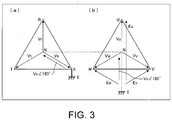
- Fig. 3 is a diagram illustrating a principle for calculating a voltage-to-ground of the commercial power system 2 according to the first embodiment of the invention.
- the leakage current calculation device 1 calculates a voltage (a voltage-to-ground) applied to the insulation resistance-to-ground of the three-phase motor 5 to calculate the insulation resistance-to-ground of the three-phase motor 5.
- the method of calculating the voltage-to-ground will be described below with reference to Fig. 3 .
- the voltage-to-ground applied to the insulation resistance-to-ground of the three-phase motor 5 is equal to a voltage between the neutral point (an N phase) of the commercial power system 2 and the ground E.
- the S phase (the S line) is grounded. Since the voltage of the S phase with respect to the neutral point is a system voltage Vs between the N phase and the S phase, the voltage between the N phase and the ground E is a voltage Vs ⁇ 180° with a phase different 180° from the phase of the system voltage Vs.
- the potential of the neutral point N of the inverter 3 is equal to the potential of the neutral point N of the commercial power system 2. Accordingly, the voltage between the neutral point N of the inverter 3 and the ground E is equal to the voltage-to-ground Vs ⁇ 180° of the commercial power system 2.
- the U-phase voltage-to-ground Eu has a value obtained by adding Vs ⁇ 180° to the voltage Vu between the N phase and the U phase.
- the V-phase voltage-to-ground Ev has a value obtained by adding Vs ⁇ 180° to the voltage Vv between the N phase and the V phase.
- the R-S line voltage is a vector sum of the voltage Vr between the neutral point (the N phase) and the R phase and the voltage-to-ground Vs.
- the voltage-to-ground calculating part 13 can calculate the system voltage Vs of the commercial power system 2 by dividing the measured R-S line voltage by ⁇ 3.
- the system voltage Vs and the voltage-to-ground Vs ⁇ 180° have the same effective value and have phases which are 180° out-of-phase from each other. Accordingly, the voltage-to-ground calculating part 13 can calculate the voltage-to-ground Vs ⁇ 180° by shifting the phase of the calculated system voltage Vs by 180°.
- Fig. 4 is a diagram illustrating a leakage current flowing between the three-phase motor 5 and the ground E in the first embodiment of the invention.
- An insulation resistance-to-ground and a stray capacitance-to-ground of the three-phase motor 5 are impedance components between a wire or a coil of the three-phase motor 5 and the ground E. They are connected in parallel to each other. Accordingly, as illustrated in (a) of Fig. 4 , the insulation resistance-to-ground Ru and the stray capacitance-to-ground Cu between the U phase on the output side of the inverter 3 and the ground E are both components constituting an impedance Zu between the U phase and the ground E.
- the insulation resistance-to-ground Rv and the stray capacitance-to-ground Cv between the V phase and the ground E are both components constituting an impedance Zv between the V phase and the ground E.
- the insulation resistance-to-ground Rw and the stray capacitance-to-ground Cw between the W phase and the ground E are both components constituting an impedance Zw between the W phase and the ground E.
- leakage currents respectively flow in the phases. Specifically, a leakage current Iu flows in the U phase, a leakage current Iv flows in the V phase, and a leakage current Iw flows in the W phase.
- the zero-phase current I0 which is measured using the zero-phase current transformer 4 is equal to a leakage current flowing through a combined impedance of the three-phase motor 5. Accordingly, in the following description, the leakage current may be referred to as a leakage current 10.
- Fig. 5 is a diagram illustrating the insulation resistance-to-ground between the three-phase motor 5 and the ground E in the first embodiment of the invention.
- the voltage-to-ground Vs ⁇ 180° is applied in-phase to the phases (U, V, and W) on the output side of the inverter 3.
- This can be said to mean that Zu, Zv, and Zw are connected in parallel to a common bus to which the voltage-to-ground Vs ⁇ 180° is applied.
- a combined impedance between the three-phase motor 5 and the ground E is defined as Z0
- the combined impedance-to-ground Z0 includes the insulation resistance-to-ground and the stray capacitance-to-ground of the three-phase motor 5 which are connected in parallel respectively as components. Accordingly, a current I0r flowing through the insulation resistance-to-ground of ZO is I0 ⁇ cos ⁇ , where a phase difference between the zero-phase current I0 and the voltage-to-ground Vs ⁇ 180° is defined as ⁇ . On the other hand, a current I0c flowing through the stray capacitance-to-ground of ZO is I0 ⁇ sin ⁇ .
- Fig. 6 is a diagram illustrating a principle for which the leakage current calculation device 1 according to the first embodiment of the invention to calculate a leakage current synchronized with the system frequency of the commercial power system 2.
- the leakage current I0 which is measured by the leakage current measuring part 12 includes a component (I0_sys) synchronized with the system frequency of the commercial power system 2 and a component (I0_inv) synchronized with the operating frequency of the inverter 3.
- I0_sys a component synchronized with the system frequency of the commercial power system 2
- I0_inv a component synchronized with the operating frequency of the inverter 3.
- the frequency (the system frequency) of a voltage supplied from the commercial power system 2 to the inverter 3 is 60 Hz
- the frequency (the operating frequency) of a voltage which is used for the inverter 3 to drive the three-phase motor 5 is 50 Hz. That is, both frequencies are set to be different from each other.
- the system frequency component extracting part 14 extracts only the leakage current I0_sys of the system frequency component from the measured leakage current I0 by performing a computing process of extracting the leakage current of the same frequency as the system frequency. Since the system frequency is different from the operating frequency, the component synchronized with the system frequency is extracted by this extraction process, but the component synchronized with the operating frequency is not extracted. Accordingly, the extracted leakage current I0_sys does not include the leakage current I0_inv synchronized with the operating frequency component of the inverter 3.
- the impedance between the three-phase motor 5 and the ground E includes both the insulation resistance-to-ground and the stray capacitance-to-ground. Since the voltage-to-ground Vs ⁇ 180° is applied to both the insulation resistance-to-ground and the stray capacitance-to-ground, the phase of the measured leakage current I0 is different from the phase of the voltage-to-ground Vs ⁇ 180° due to an influence of the stray capacitance-to-ground. Accordingly, the phase difference ⁇ of the leakage current I0_sys extracted from the leakage current I0 is different from the phase of the voltage-to-ground Vs ⁇ 180°.
- the leakage current component extracted from the leakage current I0 includes only the leakage current I0_sys. Accordingly, the phase difference ⁇ between the voltage-to-ground Vs ⁇ 180° and the leakage current component (I0_sys) is always constant regardless of the measuring time points.
- the value of the projected point is an effective value of I0R_sys.
- a vector connecting the origin of the planar coordinate system to a point obtained by projecting the end point P0 onto the vertical axis of the planar coordinate system accurately corresponds to a capacitance leakage current I0C_sys of the system frequency component. That is, the value of the projected point is an effective value of I0C_sys.
- the leakage current calculation device 1 can accurately calculate the leakage current I0_sys corresponding to the system frequency by extracting a component synchronized with the system frequency from the measured leakage current 10. As a result, it is possible to accurately calculate the insulation resistance-to-ground of the three-phase motor 5 using the voltage-to-ground Vs ⁇ 180° and the leakage current I0R_sys.
- the system frequency component extracting part 14 cannot distinguish a component synchronized with the system frequency and a component synchronized with the operating frequency which are included in the leakage current 10. Accordingly, when the system frequency component extracting part 14 performs the process of extracting the component synchronized with the system frequency from the leakage current 10, a leakage current I0_mix in which the leakage current I0_sys synchronized with the system frequency and the leakage current I0_inv synchronized with the operating frequency are mixed is extracted as a result.
- the vector which is drawn in the planar coordinate system is a combined vector (the vector I0_mix) of the vector of I0_sys and the vector of I0_inv.
- the position of an end point of the combined vector changes depending on the measuring time points, such as a point P1 (a specific point), a point P2 (a specific point), and a point P3 (a specific point), due to an influence of I0_inv.
- this change is occurs such that the end points describe a circle 61.
- Fig. 7 is a diagram illustrating a principle in which an end point rotates when an extracted leakage current component is expressed as a vector in a case in which the system frequency and the operating frequency are the same in the first embodiment of the invention.
- both frequencies will be strictly slightly different from each other. For example, when both frequencies are respectively set to 60 Hz, a slight difference is present therebetween like a case in which the system frequency is 60.00 Hz while the operating frequency is 60.01 Hz. Due to the frequency difference, as illustrated in (a) of Fig. 7 , a waveform 71 of I0_sys and a waveform 72 of I0_inv become gradually different from each other as the measuring time point transitions slowly to PI, P2, and P3.
- the leakage current I0_mix extracted from the leakage current I0 includes the leakage current I0_sys corresponding to the system frequency and the leakage current I0_inv corresponding to the operating frequency.
- the determined phase difference ⁇ is a phase difference between the voltage-to-ground Vs ⁇ 180° and the leakage current I0_mix and thus the value of the phase difference ⁇ changes with the elapse of time due to a difference between the waveform of I0_sys and the waveform of I0_inv included in the leakage current I0_inv. Accordingly, the position of the end point when the leakage current I0_mix is expressed as a vector changes with the elapse of time.
- the positions of the end points (specific points) P1 to P3 of the leakage current I0 change to correspond to differences between the waveforms of P1 to P3 in (a) of Fig. 7 .
- the phase difference ⁇ changes with the elapse of time due to the change and thus the end point of I0_mix describes a circle 73 with the elapse of time as illustrated in (b) of Fig. 7 . That is, P1 to P3 are plotted onto the circle 73 in principle.
- the end point of I0_sys matches the center 74 of the circle 73. Accordingly, the leakage current calculation device 1 according to this embodiment accurately calculates I0R_sys and I0C_inv by calculating the center 74 and projecting the center 74 onto the horizontal axis and the vertical axis respectively of the planar coordinate system.
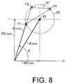
- Fig. 8 is a diagram illustrating a first method for calculating an insulation resistance-to-ground leakage current in the first embodiment of the invention.
- the system frequency component extracting part 14 extracts I0_mix at three different time points.
- the phase difference calculating part 15 calculates the phase difference ⁇ at the three different time points.
- the circle center calculating part 16 calculates the points P1 to P3 which are end points when each I0_mix is expressed as a vector on the basis of the leakage currents I0_mix and the phase differences ⁇ which are determined at the three different time points.
- the circle center calculating part 16 calculates a circumcenter of a triangle 81 with the points P1 to P3 as vertices instead of directly calculating a circle 82 passing through the points P1 to P3.
- the circumcenter is the same as the center 83 of the circle 82 which circumscribes the triangle 81.
- the circle center calculating part 16 can calculate the center 83 of the circle 82 passing through the points by calculating the circumcenter of the triangle 81 with the points P1 to P3 as vertices.
- the circle center calculating part 16 outputs the calculated center 83 to the resistance leakage current calculating part 17.
- a vector with the origin of the planar coordinate system as a start point and with the center 83 as an end point is the same as the leakage current I0_sys corresponding to the system frequency in the leakage current I0_mix extracted from the leakage current 10. Therefore, the resistance leakage current calculating part 17 can calculate the insulation resistance-to-ground leakage current I0R_sys in the leakage current I0_sys corresponding to the system frequency by projecting the calculated center 83 onto the horizontal axis.
- the resistance leakage current calculating part 17 outputs the calculated leakage current I0R_sys to the insulation resistance calculating part 18.
- the insulation resistance calculating part 18 calculates the insulation resistance-to-ground of the three-phase motor 5 using the leakage current I0R_sys and the voltage-to-ground Vs ⁇ 180°.
- the center 83 is calculated using only three points P1 to P3. That is, since it suffices to measure the leakage current I0 has only to be measured at three different time points to calculate the leakage current I0R_sys, it is possible to fast calculate the I0R_sys.
- Fig. 9 is a diagram illustrating a second method for calculating the insulation resistance-to-ground leakage current in the first embodiment of the invention.
- the system frequency component extracting part 14 extracts I0_mix at four or more different time points.
- the phase difference calculating part 15 calculates the phase difference ⁇ at the four or more different time points.
- the circle center calculating part 16 calculates an equation of a circle 91 passing through the points Pn.
- the center 92 of the circle 91 is calculated using the equation.
- the circle center calculating part 16 calculates the equation of the circle 91 using a least squares method of a circle using the calculated points Pn. Hereinafter, this method will be more specifically described.
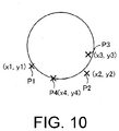
- Fig. 10 is a diagram illustrating a least square method of a circle in the first embodiment of the invention.
- the points Pn are calculated as a point P1(x1, y1), a point P2 (x2, y2), a point P3 (x3, y3), a point P4 (x4, y4), ....
- a B C ⁇ x 2 ⁇ xy ⁇ x ⁇ xy ⁇ y 2 ⁇ y ⁇ x 2 ⁇ y ⁇ 1 ⁇ 1 ⁇ x 3 + x y 2 ⁇ x 2 y + y 2 ⁇ x 2 + y 2
- the parameters A, B, and C are determined by solving the matrix expression. By substituting the determined parameters A, B, and C into the above-mentioned relational expression, the coefficients a, b, and r can be determined. Accordingly, since the equation of the circle 91 is calculated, the center 92 is calculated using the equation. The calculation of the insulation resistance-to-ground leakage current I0_sys based on the center 92 and the calculation of the insulation resistance-to-ground of the three-phase motor 5 based on the leakage current I0_sys and the voltage-to-ground Vs ⁇ 180° are the same as in the above-mentioned example.
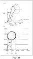
- Fig. 11 is a diagram illustrating a third method for calculating the insulation resistance-to-ground leakage current in the first embodiment of the invention.
- the system frequency component extracting part 14 calculates a minimum value of the insulation resistance-to-ground leakage current in I0_mix and a maximum value of the insulation resistance-to-ground leakage current in I0_mix within a fixed time and calculates a median value therebetween as I0R_sys.
- the system frequency component extracting part 14 extracts I0_mix at each time point over a fixed time (preferably, a long time equal to or longer than 60 seconds), that is, until points corresponding to one round (turn) or more of a circle are calculated.
- the phase difference calculating part 15 calculates the phase difference ⁇ at the each time point until points corresponding to one round (turn) or more of a circle are calculated.
- the circle center calculating part 16 does not calculate a center of a circle.
- the insulation resistance calculating part 18 performs the calculation of I0R_mix at each time point over a long time (60 seconds or more).
- the value of I0R_mix is equal to a value on the horizontal axis at a point obtained by projecting an end point when I0_mix is expressed as a vector onto the horizontal axis. Since the end point describes a circle as described above, the point obtained by projecting the end point onto the horizontal axis is always present on a line acquired by projecting a whole circle onto the horizontal axis. Accordingly, for the calculated I0R_mix, a minimum value 111 and a maximum value 112 respectively corresponding to ends of the line are naturally determined.
- a median value 113 between the minimum value 111 and the maximum value 112 corresponds to the center of the circle.
- the resistance leakage current calculating part 17 can calculate I0R_sys by calculating the median value 113.
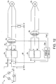
- Fig. 12 is a system diagram schematically illustrating a configuration example of a configuration in which a leakage current calculation device 1 according to a second embodiment of the invention is employed.
- the configuration of the leakage current calculation device 1 is basically the same as in the first embodiment.
- a single leakage current calculation device 1 can monitor each of a plurality of three-phase motors 5a and 5b as illustrated in Fig. 12 .
- the three-phase motors 5a and 5b are driven by inverters 3a and 3b, respectively, Respective input sides of the inverters 3a and 3b are both connected to a common commercial power system 2. An output side of the inverter 3a is connected to the three-phase motor 5a, while and an output side of the inverter 3b is connected to the three-phase motor 5b.
- a zero-phase current transformer 4a is disposed between the inverter 3a and the three-phase motor 5a, while a zero-phase current transformer 4b is disposed between the inverter 3b and the three-phase motor 5b.
- the zero-phase current transformers 4a and 4b are both connected to the leakage current measuring part 12 of the leakage current calculation device 1.
- the leakage current calculation device 1 calculates an insulation resistance-to-ground leakage current and an insulation resistance-to-ground corresponding to each of the three-phase motors 5a and 5b. The calculation procedure thereof will be described below.
- the voltage measuring part 11 measures at least one of line voltages on the input side of any of the plurality of inverters 3a and 3b. Since the input sides of the inverters 3a and 3b are connected to the common commercial power system 2, for example, a voltage Rs between the R phase and the S phase of the inverter 3a is completely equal to a voltage Rs between the R phase and the S phase of the inverter 3b. In this way, in this embodiment, since the voltage Rs may be measured at only one position, it is possible to simplify the configuration of the leakage current calculation device 1.
- the voltage-to-ground calculating part 13 calculates the voltage-to-ground Vs ⁇ 180° on the basis of the voltage Rs measured on the input side of the inverter 3a. Since the voltage Rs is common to the inverters 3a and 3b, the leakage current calculation device 1 uses the voltage-to-ground Vs ⁇ 180° as a voltage-to-ground common to the three-phase motor 5a and the three-phase motor 5b in the following process.
- the leakage current measuring part 12 measures a leakage current of the three-phase motor 5a using the zero-phase current transformer 4a and measure a leakage current of the three-phase motor 5b using the zero-phase current transformer 4b. That is, the leakage current calculation device 1 includes a single leakage current measuring part 12 which is common to the three-phase motors 5a and 5b.
- the leakage current calculation device 1 may include a plurality of leakage current measuring parts 12a and 12b respectively corresponding to the three-phase motors 5a and 5b.
- the leakage current measuring part 12a is connected to the zero-phase current transformer 4a
- the leakage current measuring part 12b is connected to the zero-phase current transformer 4b.
- the leakage current measuring part 12a measures the leakage current of the three-phase motor 5a using the zero-phase current transformer 4a
- the leakage current measuring part 12b measures the leakage current of the three-phase motor 5b using the zero-phase current transformer 4b.
- the system frequency component extracting part 14 extracts a leakage current component corresponding to the three-phase motor 5a from the leakage current of the three-phase motor 5a. On the other hand, the system frequency component extracting part 14 extracts a leakage current component corresponding to the three-phase motor 5b from the leakage current of the three-phase motor 5b.
- the phase difference calculating part 15 calculates a phase difference between the calculated voltage-to-ground and the leakage current component of the three-phase motor 5a.
- the phase difference calculating part 15 further calculates a phase difference between the calculated voltage-to-ground and the leakage current component of the three-phase motor 5b.
- the resistance leakage current calculating part 17 calculates an insulation resistance-to-ground leakage current of the three-phase motor 5a on the basis of a center of a circle corresponding to the three-phase motor 5a.
- the resistance leakage current calculating part 17 calculates an insulation resistance-to-ground leakage current of the three-phase motor 5b on the basis of a center of a circle corresponding to the three-phase motor 5b.
- the insulation resistance calculating part 18 calculates an insulation resistance-to-ground of the three-phase motor 5a from the voltage-to-ground Vs ⁇ 180° and the insulation resistance-to-ground leakage current of the three-phase motor 5a.
- the insulation resistance calculating part 18 calculates an insulation resistance-to-ground of the three-phase motor 5b from the voltage-to-ground Vs ⁇ 180° and the insulation resistance-to-ground leakage current of the three-phase motor 5b.
- Fig. 13 is a diagram illustrating an example of change of a calculated value of the insulation resistance-to-ground leakage current or the insulation resistance-to-ground over time for each three-phase motor 5 in the second embodiment of the invention. Changes of the respective insulation resistance-to-ground leakage currents of the three-phase motors 5a and 5b over time are illustrated in (a) of Fig. 13 .
- Ch1 corresponds to the three-phase motor 5a
- Ch2 corresponds to the three-phase motor 5b.
- changes of the respective insulation resistance-to-ground of the three-phase motors 5a and 5b over time are illustrated in (b) of Fig. 13 .
- Ch1 corresponds to the three-phase motor 5a
- Ch2 corresponds to the three-phase motor 5b.
- the change of the insulation resistance-to-ground leakage current or the insulation resistance-to-ground over time is different between the three-phase motors 5a and 5b.
- the leakage current calculation device 1 can appropriately specify the three-phase motor 5 which has deteriorated in insulation by comparing the values with each other or comparing each of the values with predetermined threshold values.
- the determination part 19 can determine degrees of insulation deterioration in the three-phase motors 5a and 5b respectively by comparing the insulation resistance-to-ground leakage current corresponding to the system frequency of the three-phase motor 5a with the insulation resistance-to-ground leakage current corresponding to the system frequency of the three-phase motor 5b. For example, in the example illustrated in (a) of Fig. 13 , a large degree of separation 131 occurs between the insulation resistance-to-ground leakage current corresponding to the system frequency of the three-phase motor 5a at a certain time point and the insulation resistance-to-ground leakage current corresponding to the system frequency of the three-phase motor 5b at the same time point. When the degree of separation 131 has been detected, the determination part 19 determines that the three-phase motor 5a having a larger insulation resistance-to-ground leakage current has deteriorated in insulation.
- the determination part 19 may specify, among the three-phase motors 5a and 5b, the three-phase motor 5a of which the corresponding insulation resistance-to-ground leakage current is greater than a predetermined threshold value among the three-phase motors 5a and 5b as the three-phase motor 5a that has deteriorated in insulation. For example, in (a) of Fig. 13 , since the insulation resistance-to-ground leakage current of the three-phase motor 5a is greater than a threshold value 132 after a certain time point, the determination part 19 can specify that the three-phase motor 5a has deteriorated in insulation after the time point.
- the determination using the degree of separation or the threshold value as described above may also be performed on the insulation resistance-to-ground of the three-phase motors 5a and 5b as illustrated in (b) of Fig. 13 in addition to the insulation resistance-to-ground leakage current.
- a large degree of separation 133 occurs between the insulation resistance-to-ground of the three-phase motor 5a at a certain time point and the insulation resistance-to-ground of the three-phase motor 5b at the same time point.
- the determination part 19 determines that the three-phase motor 5a having a smaller insulation resistance-to-ground has deteriorated in insulation.
- the determination part 19 can specify that the three-phase motor 5a has deteriorated in insulation after the time point.
- the leakage current measuring part 12 for measuring the leakage current of the three-phase motor 5 which is not monitored is not necessary.
- the leakage current calculation device 1 includes the unnecessary leakage current measuring part 12, it causes an unnecessary increase in costs of the leakage current calculation device 1.
- the leakage current measuring parts 12 may be extension parts for measuring a leakage current.
- the leakage current measuring parts 12 since a necessary number of leakage current measuring parts 12 can be attached to the leakage current calculation device 1 or an unnecessary leakage current measuring part 12 can be detached from the leakage current calculation device 1, it is possible to curb the cost of the leakage current calculation device 1.
- a technique disclosed in Japanese Laid-open No. 2013-181813 can be used to implement the leakage current measuring part 12 as such an extension part.
- a leakage current calculation device includes: a voltage measuring part that measures at least one of line voltages on an input side of an inverter with a three-phase AC commercial power system, in which one of three different phases is grounded, as a power source; a voltage-to-ground calculating part that calculates a voltage-to-ground between a neutral point of the commercial power system and the ground from the at least one line voltage measured by the voltage measuring part; a leakage current measuring part that measures a leakage current flowing between a load connected to an output side of the inverter and the ground; a frequency component extracting part that extracts a leakage current component synchronized with a system frequency of the commercial power system from the measured leakage current; a phase difference determining part that determines a phase difference between the calculated voltage-to-ground and the extracted leakage current component; and a leakage current calculating part that calculates an insulation resistance-to-ground leakage current corresponding to the system frequency
- the leakage current component extracted from the leakage current includes both the leakage current synchronized with the system frequency and the leakage current synchronized with the operating frequency. Since both frequencies are not strictly the same but are slightly different, the phase difference between the voltage-to-ground and the leakage current component becomes different at each measuring time point. Accordingly, the points which are defined by the leakage current components and the phase differences change at each measuring time point and describe a circle.
- the leakage current calculation device calculates the insulation resistance-to-ground leakage current corresponding to the system frequency which flows through the insulation resistance-to-ground of the load between the load and the ground on the basis of the center of the circle which is described by specific points specified by the leakage current component extracted and the phase difference calculated at three or more different time points.
- the center of the circle corresponds to an end point of a vector indicating the leakage current corresponding to the system frequency included in the leakage current component. Accordingly, the leakage current calculation device can accurately calculate the insulation resistance-to-ground leakage current in the leakage current corresponding to the system frequency on the basis of the center.
- the leakage current calculation device As described above, with the leakage current calculation device according to the first aspect of the invention, it is possible to accurately calculate the insulation resistance-to-ground leakage current corresponding to the system frequency when the system frequency of the commercial power system and the operating frequency of the inverter device are the same.
- a leakage current calculation device is the leakage current calculation device according to the first aspect, further including an insulation resistance-to-ground calculating part that calculates an insulation resistance-to-ground of the load on the output side of the inverter on the basis of the calculated voltage-to-ground and the calculated insulation resistance-to-ground leakage current corresponding to the system frequency.
- a leakage current calculation device is the leakage current calculation device according to the first or second aspect, wherein the leakage current calculating part specifies the center of the circle on the basis of an equation of a circumscribed circle which circumscribes a triangle defined by three of the specific points.
- a leakage current calculation device is the leakage current calculation device according to the first or second aspect, wherein the leakage current calculating part specifies the center of the circle on the basis of a least squares method of the circle.
- a leakage current calculation device is the leakage current calculation device according to the first or second aspect, wherein, on the basis of the leakage current component extracted and the phase difference determined at each time point within a fixed time, the leakage current calculating part calculates the insulation resistance-to-ground leakage current the each time point and calculates a median value between a maximum value and a minimum value of the calculated values as the insulation resistance-to-ground leakage current corresponding to the system frequency.
- a leakage current calculation device is as follows.
- a plurality of the loads are separately connected to respective output sides of a plurality of the inverters, respectively, the input side of each of the plurality of the inverters is connected to the same commercial power system
- the voltage measuring part measures at least one of the line voltages on the input side of any of the plurality of the inverters
- the leakage current measuring part measures a plurality of the leakage currents respectively corresponding to the plurality of the loads
- the frequency component extracting part extracts a plurality of the leakage current components respectively corresponding to the plurality of the loads from a plurality of the measured leakage currents
- the phase difference determining part determines a plurality of phase differences on the basis of the calculated voltage-to-ground and the plurality of the extracted leakage current components
- the leakage current calculating part calculates a plurality of insulation resistance-to-ground leakage currents corresponding to the system frequency and respectively corresponding to the loads on the basis of
- the insulation resistance-to-ground leakage currents corresponding to the system frequency of a plurality of different loads can be calculated using a single leakage current calculation device. Since measurement of a voltage by the voltage measuring part may be performed on the input side of any of a plurality of inverters, the measurement of a voltage can be limited to one position. Accordingly, it is possible to simplify the configuration of the leakage current calculation device.
- a leakage current calculation device is the leakage current calculation device according to the sixth aspect, further including an insulation-deteriorated load specifying part that specifies the load of which the corresponding insulation resistance-to-ground leakage current corresponding to the system frequency is greater than a predetermined threshold value among the plurality of the loads as the load which has deteriorated in insulation.
- a leakage current calculation device is the leakage current calculation device according to the sixth or seventh aspect, further including insulation deterioration determining part that determines degrees of insulation deterioration in a plurality of the loads respectively by comparing the plurality of the insulation resistance-to-ground leakage currents corresponding to the system frequency.
- a leakage current calculation method includes: a voltage measuring step of measuring at least one of line voltages on an input side of an inverter with a three-phase AC commercial power system, in which any of three different phases is grounded, as a power source; a voltage-to-ground calculating step of calculating a voltage-to-ground between a neutral point of the commercial power system and the ground from the measured at least one line voltage; a leakage current measuring step of measuring a leakage current flowing between a load connected to an output side of the inverter and the ground; a frequency component extracting step of extracting a leakage current component synchronized with a system frequency of the commercial power system from the measured leakage current; a phase difference determining step of determining a phase difference between the calculated voltage-to-ground and the determined leakage current component; and a leakage current calculating step of calculating an insulation resistance-to-ground leakage current corresponding to the system frequency, which flows through an
Landscapes
- Physics & Mathematics (AREA)
- General Physics & Mathematics (AREA)
- Engineering & Computer Science (AREA)
- Power Engineering (AREA)
- Nonlinear Science (AREA)
- Mathematical Physics (AREA)
- Testing Of Short-Circuits, Discontinuities, Leakage, Or Incorrect Line Connections (AREA)
- Tests Of Circuit Breakers, Generators, And Electric Motors (AREA)
- Emergency Protection Circuit Devices (AREA)
- Measurement Of Current Or Voltage (AREA)
Abstract
Description
- The invention relates to a leakage current calculation device and a leakage current calculation method that calculates a leakage current.
- As an example of technology of calculating a leakage current in a load of a three-phase motor or the like, a leakage current calculation device that calculates a value of a leakage current flowing through an insulation resistance-to-ground component other than a capacitance-to-ground component of the three-phase motor in a leakage current-to-ground by integrating a zero-phase current component in a frequency band in a period corresponding to zero-crossings of a basic AC frequency waveform is disclosed in
Patent Literature 1. - Japanese Unexamined Patent Application Publication No.
2014-228519 (published on December 8, 2014 - The leakage current calculation device of
Patent Literature 1 can accurately calculate a leakage current flowing through an insulation resistance-to-ground component when a frequency of a commercial power system and an operating frequency of an inverter device are set to difference values. However, when the frequency of the commercial power system and the operating frequency of the inverter device are set to the same value, there is concern that an error will occur in the calculated leakage current. - The invention is made to solve the above-mentioned problem and an object thereof is to provide a leakage current calculation device and a leakage current calculation method that can accurately calculate an insulation resistance-to-ground leakage current corresponding to a system frequency when the system frequency of a commercial power system and an operating frequency of an inverter device are the same.
- In order to solve the above-mentioned problem, a leakage current calculation device according to an aspect of the invention includes: a voltage measuring part that measures at least one of line voltages on an input side of an inverter with a three-phase AC commercial power system, in which any of three different phases is grounded, as a power source; a voltage-to-ground calculating part that calculates a voltage-to-ground between a neutral point of the commercial power system and the ground from the at least one line voltage measured by the voltage measuring part; a leakage current measuring part that measures a leakage current flowing between a load connected to an output side of the inverter and the ground; a frequency component extracting part that extracts a leakage current component synchronized with a system frequency of the commercial power system from the measured leakage current; a phase difference determining part that determines a phase difference between the calculated voltage-to-ground and the extracted leakage current component; and a leakage current calculating part that calculates an insulation resistance-to-ground leakage current corresponding to the system frequency, which flows through an insulation resistance-to-ground of the load between the load and the ground on the basis of a center of a circle which is described by specific points which are specified by the leakage current component extracted and the phase difference determined at three or more different time points.
- In order to achieve the above-mentioned object, a leakage current calculation method according to another aspect of the invention includes: a voltage measuring step of measuring at least one of line voltages on an input side of an inverter with a three-phase AC commercial power system, in which one of three different phases is grounded, as a power source; a voltage-to-ground calculating step of calculating a voltage-to-ground between a neutral point of the commercial power system and the ground from the measured at least one line voltage; a leakage current measuring step of measuring a leakage current flowing between a load connected to an output side of the inverter and the ground; a frequency component extracting step of extracting a leakage current component synchronized with a system frequency of the commercial power system from the measured leakage current; a phase difference determining step of determining a phase difference between the calculated voltage-to-ground and the determined leakage current component; and a leakage current calculating step of calculating an insulation resistance-to-ground leakage current corresponding to the system frequency, which flows through an insulation resistance-to-ground of the load between the load and the ground on the basis of a center of a circle which is described by specific points which are specified by the leakage current component and the phase difference which are extracted and determined at three or more different time points.
- According to the invention, it is possible to accurately calculate an insulation resistance-to-ground leakage current corresponding to a system frequency when the system frequency of a commercial power system and an operating frequency of an inverter device are the same.
-
-
Fig. 1 is a block diagram illustrating a configuration of principal parts of a leakage current calculation device according to a first embodiment of the invention. -
Fig. 2 is a system diagram schematically illustrating a configuration example in which the leakage current calculation device according to the first embodiment of the invention is employed. -
Fig. 3 is a diagram illustrating a principle for calculating a voltage-to-ground of a commercial power system according to the first embodiment of the invention. -
Fig. 4 is a diagram illustrating a leakage current flowing between a three-phase motor and the ground in the first embodiment of the invention. -
Fig. 5 is a diagram illustrating an insulation resistance-to-ground between the three-phase motor and the ground in the first embodiment of the invention. -
Fig. 6 is a diagram illustrating a principle for the leakage current calculation device according to the first embodiment of the invention to calculate a leakage current synchronized with the system frequency of the commercial power system. -
Fig. 7 is a diagram illustrating a principle in which an end point rotates when an extracted leakage current is expressed as a vector in a case in which a system frequency and an operating frequency are the same in the first embodiment of the invention. -
Fig. 8 is a diagram illustrating a first method for calculating an insulation resistance-to-ground leakage current in the first embodiment of the invention. -
Fig. 9 is a diagram illustrating a second method for calculating the insulation resistance-to-ground leakage current in the first embodiment of the invention. -
Fig. 10 is a diagram illustrating a least squares method of a circle in the first embodiment of the invention. -
Fig. 11 is a diagram illustrating a third method for calculating the insulation resistance-to-ground leakage current in the first embodiment of the invention. -
Fig. 12 is a system diagram schematically illustrating a configuration example in which a leakage current calculation device according to a second embodiment of the invention is employed. -
Fig. 13 is a diagram illustrating an example of change of a calculated value of an insulation resistance-to-ground leakage current or an insulation resistance-to-ground over time for each three-phase motor in the second embodiment of the invention. - A first embodiment of the invention will be described below with reference to
Figs. 1 to 11 . -
Fig. 2 is a system diagram schematically illustrating a configuration example in which a leakagecurrent calculation device 1 according to the first embodiment of the invention is employed. In the example illustrated in the drawing, the leakagecurrent calculation device 1 is configured to monitor a three-phase motor 5 (a load) such as a servomotor which is driven by aninverter 3 with acommercial power system 2 as a power source. - The
commercial power system 2 is a three-phase alternating type AC power source in which an S phase of three different phases (an R phase, an S phase, and a T phase) is grounded to the ground E. The three phases are respectively connected to an input side of theinverter 3 via an R line, an S line, and a T line. - The
inverter 3 generates predetermined control voltages from three-phase electric power supplied from thecommercial power system 2 and outputs the control voltages to the three-phase motor 5 respectively via three lines (a U line, a V line, and a W line) corresponding to three phases (a U phase, a V phase, and a W phase) on an output side. The three-phase motor 5 is connected to the output side of theinverter 3 and operates using the supplied control voltages. - A zero-
phase current transformer 4 surrounding the U line, the V line, and the W line is provided between theinverter 3 and the three-phase motor 5. The zero-phase current transformer 4 measures a combined zero-phase current I0 of three phases flowing between theinverter 3 and the three-phase motor 5. Although details thereof will be described later, the zero-phase current I0 is equal to a leakage current flowing between the three-phase motor 5 and the ground E. -
Fig. 1 is a block diagram illustrating a configuration of principal parts of the leakage current calculation device according to the first embodiment of the invention. As illustrated in the drawing, the leakagecurrent calculation device 1 includes avoltage measuring part 11, a leakagecurrent measuring part 12, a voltage-to-ground calculating part 13, a system frequency component extracting part 14 (a frequency component extracting part), a phase difference calculating part 15 (a phase difference determining part), a circlecenter calculating part 16, a resistance leakage current calculating part 17 (a leakage current calculating part), an insulationresistance calculating part 18, a determination part 19 (an insulation-deteriorated load specifying part and an insulation deterioration determining part), and anoutput part 20. - The
voltage measuring part 11 measures at least one of line voltages on an input side of theinverter 3. In this embodiment, the line voltage between the R phase and the S phase on the input side of theinverter 3 is measured. The line voltage to be measured is not limited thereto, and an arbitrary line voltage can be measured. For example, thevoltage measuring part 11 may measure a voltage between the R phase and the T phase or a voltage between the T phase and the S phase. Thevoltage measuring part 11 may include a low-pass filter or a band-pass filter for removing a high-frequency component from the measured voltage or extracting a system frequency component from the measured voltage. - The voltage-to-
ground calculating part 13 calculates a voltage-to-ground between a neutral point of thecommercial power system 2 and the ground E from at least one of the line voltages measured by thevoltage measuring part 11. In this embodiment, the voltage-to-ground is calculated from the line voltage between the R line and the S line. - The leakage
current measuring part 12 measures a leakage current (a zero-phase current) flowing between the three-phase motor 5 and the ground E using the zero-phasecurrent transformer 4. The leakagecurrent measuring part 12 may include a low-pass filter or a band-pass filter for removing a high-frequency component from the measured leakage current or extracting a system frequency component from the measured leakage current. - The system frequency
component extracting part 14 extracts a leakage current component synchronized with the system frequency of the commercial power system 2 (that is, a leakage current component of the same frequency as the system frequency) from the measured leakage current. For example, discrete Fourier transform (DFT) or fast Fourier transform (FFT) may be used for the extraction process. - The phase
difference calculating part 15 calculates a phase difference between the calculated voltage-to-ground and the extracted leakage current component. The calculation of the phase difference is performed, for example, by a computing process, but the phase difference may be determined by measuring a phase difference using a predetermined measurement circuit instead. - The circle
center calculating part 16 calculates a center of a circle which is described by points (specific points) specified by the leakage current components calculated and the phase differences determined at three or more different time points. - The resistance leakage
current calculating part 17 calculates a current (an insulation resistance-to-ground leakage current corresponding to the system frequency) flowing through an insulation resistance-to-ground of the three-phase motor 5 between the three-phase motor 5 and the ground E on the basis of the calculated center of the circle. - The insulation
resistance calculating part 18 calculates the insulation resistance-to-ground of the three-phase motor 5 using the calculated insulation resistance-to-ground leakage current corresponding to the system frequency and the calculated voltage-to-ground. - The
determination part 19 determines whether insulation failure (insulation deterioration) has occurred in the three-phase motor 5 on the basis of the calculated insulation resistance-to-ground leakage current corresponding to the system frequency or the calculated insulation resistance-to-ground. - The
output part 20 outputs the determination result of insulation failure outside the leakagecurrent calculation device 1 in a desired format. This output is performed, for example, by screen display, communication output, or contact signal output. -
Fig. 3 is a diagram illustrating a principle for calculating a voltage-to-ground of thecommercial power system 2 according to the first embodiment of the invention. The leakagecurrent calculation device 1 according to this embodiment calculates a voltage (a voltage-to-ground) applied to the insulation resistance-to-ground of the three-phase motor 5 to calculate the insulation resistance-to-ground of the three-phase motor 5. The method of calculating the voltage-to-ground will be described below with reference toFig. 3 . - The voltage-to-ground applied to the insulation resistance-to-ground of the three-
phase motor 5 is equal to a voltage between the neutral point (an N phase) of thecommercial power system 2 and the ground E. In thecommercial power system 2, as illustrated in (a) ofFig. 3 , the S phase (the S line) is grounded. Since the voltage of the S phase with respect to the neutral point is a system voltage Vs between the N phase and the S phase, the voltage between the N phase and the ground E is a voltage Vs∠180° with a phase different 180° from the phase of the system voltage Vs. - On the other hand, as illustrated in (b) of
Fig. 3 , the potential of the neutral point N of theinverter 3 is equal to the potential of the neutral point N of thecommercial power system 2. Accordingly, the voltage between the neutral point N of theinverter 3 and the ground E is equal to the voltage-to-ground Vs∠180° of thecommercial power system 2. As illustrated in (b) ofFig. 3 , the U-phase voltage-to-ground Eu has a value obtained by adding Vs∠180° to the voltage Vu between the N phase and the U phase. The V-phase voltage-to-ground Ev has a value obtained by adding Vs∠180° to the voltage Vv between the N phase and the V phase. The W-phase voltage-to-ground Ew has a value obtained by adding Vs∠180° to the voltage Vw between the N phase and the W phase. That is, Eu=Vu+VsZ180°, Ev=Vv+VsZ180°, and Ew=Vw+VsZ180° are established. - Here, since the U-phase voltage Vu, the V-phase voltage Vv, and the W-phase voltage Vw are 120° out-of-phase from each other, the phase voltages have a characteristic that the sum of the phase voltages is zero. That is, Vu+Vv+Vw=0 is established. Accordingly, the voltage Vs∠180° is a voltage-to-ground corresponding to the system frequency of the
commercial power system 2 which is applied to the insulation resistance-to-ground of the three-phase motor 5. - As illustrated in (a) of
Fig. 3 , the R-S line voltage is a vector sum of the voltage Vr between the neutral point (the N phase) and the R phase and the voltage-to-ground Vs. The voltage-to-ground calculating part 13 can calculate the system voltage Vs of thecommercial power system 2 by dividing the measured R-S line voltage by √3. The system voltage Vs and the voltage-to-ground Vs∠180° have the same effective value and have phases which are 180° out-of-phase from each other. Accordingly, the voltage-to-ground calculating part 13 can calculate the voltage-to-ground Vs∠180° by shifting the phase of the calculated system voltage Vs by 180°. -
Fig. 4 is a diagram illustrating a leakage current flowing between the three-phase motor 5 and the ground E in the first embodiment of the invention. - An insulation resistance-to-ground and a stray capacitance-to-ground of the three-
phase motor 5 are impedance components between a wire or a coil of the three-phase motor 5 and the ground E. They are connected in parallel to each other. Accordingly, as illustrated in (a) ofFig. 4 , the insulation resistance-to-ground Ru and the stray capacitance-to-ground Cu between the U phase on the output side of theinverter 3 and the ground E are both components constituting an impedance Zu between the U phase and the ground E. - Similarly, the insulation resistance-to-ground Rv and the stray capacitance-to-ground Cv between the V phase and the ground E are both components constituting an impedance Zv between the V phase and the ground E. The insulation resistance-to-ground Rw and the stray capacitance-to-ground Cw between the W phase and the ground E are both components constituting an impedance Zw between the W phase and the ground E.
- As illustrated in (b) of
Fig. 4 , on the output side of theinverter 3, leakage currents respectively flow in the phases. Specifically, a leakage current Iu flows in the U phase, a leakage current Iv flows in the V phase, and a leakage current Iw flows in the W phase. The zero-phase current I0 flowing on the output side of theinverter 3 is equal to the total sum of the leakage currents flowing of the phases. Accordingly, I0=Iu+Iv+Iw is established. - When paying attention to a system frequency component, the voltage-to-ground Vs∠180° is applied in-phase to the phases (U, V, and W) on the output side of the
inverter 3. Accordingly, Iu=Vs∠180°÷Zu, Iv=Vs∠180°÷Zu, and Iv=Vs∠180°÷Zu are established. As a result, I0=Vs∠180°÷(1÷Zu+1÷Zv+1÷Zw) is established. - As described above, the zero-phase current I0 which is measured using the zero-phase
current transformer 4 is equal to a leakage current flowing through a combined impedance of the three-phase motor 5. Accordingly, in the following description, the leakage current may be referred to as a leakage current 10. -
Fig. 5 is a diagram illustrating the insulation resistance-to-ground between the three-phase motor 5 and the ground E in the first embodiment of the invention. - When paying attention to the system frequency component, the voltage-to-ground Vs∠180° is applied in-phase to the phases (U, V, and W) on the output side of the
inverter 3. This can be said to mean that Zu, Zv, and Zw are connected in parallel to a common bus to which the voltage-to-ground Vs∠180° is applied. Accordingly, when a combined impedance between the three-phase motor 5 and the ground E is defined as Z0, 1÷Z0=1÷Zu+1÷Zv+1÷Zw is established. This equation is modified to I0=Vs∠180°÷Z0 and thus Z0=Vs∠180°÷I0 is established. - The combined impedance-to-ground Z0 includes the insulation resistance-to-ground and the stray capacitance-to-ground of the three-
phase motor 5 which are connected in parallel respectively as components. Accordingly, a current I0r flowing through the insulation resistance-to-ground of ZO is I0×cosθ, where a phase difference between the zero-phase current I0 and the voltage-to-ground Vs∠180° is defined as θ. On the other hand, a current I0c flowing through the stray capacitance-to-ground of ZO is I0×sinθ. - Accordingly, the insulation resistance-to-ground R0 of the three-
phase motor 5 is calculated by R0=Vs∠180°÷I0r. On the other hand, the stray capacitance-to-ground C0 of the three-phase motor 5 is calculated by C0=Vs∠180°÷I0c. -
Fig. 6 is a diagram illustrating a principle for which the leakagecurrent calculation device 1 according to the first embodiment of the invention to calculate a leakage current synchronized with the system frequency of thecommercial power system 2. - The leakage current I0 which is measured by the leakage
current measuring part 12 includes a component (I0_sys) synchronized with the system frequency of thecommercial power system 2 and a component (I0_inv) synchronized with the operating frequency of theinverter 3. In order to calculate the insulation resistance-to-ground of the three-phase motor 5, it is necessary to extract only the leakage current I0_sys which is a leakage current component synchronized with the system frequency from the leakage current 10. - In (a) of
Fig. 6 , the frequency (the system frequency) of a voltage supplied from thecommercial power system 2 to theinverter 3 is 60 Hz, and the frequency (the operating frequency) of a voltage which is used for theinverter 3 to drive the three-phase motor 5 is 50 Hz. That is, both frequencies are set to be different from each other. - In this case, the system frequency
component extracting part 14 extracts only the leakage current I0_sys of the system frequency component from the measured leakage current I0 by performing a computing process of extracting the leakage current of the same frequency as the system frequency. Since the system frequency is different from the operating frequency, the component synchronized with the system frequency is extracted by this extraction process, but the component synchronized with the operating frequency is not extracted. Accordingly, the extracted leakage current I0_sys does not include the leakage current I0_inv synchronized with the operating frequency component of theinverter 3. - The impedance between the three-
phase motor 5 and the ground E includes both the insulation resistance-to-ground and the stray capacitance-to-ground. Since the voltage-to-ground Vs∠180° is applied to both the insulation resistance-to-ground and the stray capacitance-to-ground, the phase of the measured leakage current I0 is different from the phase of the voltage-to-ground Vs∠180° due to an influence of the stray capacitance-to-ground. Accordingly, the phase difference θ of the leakage current I0_sys extracted from the leakage current I0 is different from the phase of the voltage-to-ground Vs∠180°. - As illustrated in (a) of
Fig. 6 , when the system frequency is different from the operating frequency, the leakage current component extracted from the leakage current I0 includes only the leakage current I0_sys. Accordingly, the phase difference θ between the voltage-to-ground Vs∠180° and the leakage current component (I0_sys) is always constant regardless of the measuring time points. - Accordingly, as illustrated in (a) of
Fig. 6 , when a vector of the leakage current I0_sys is drawn with an origin in a planar coordinate system as a start point and with an angle of the phase difference θ provided on the horizontal axis of the planar coordinate system, it can be noticed that an end point P0 of the vector is always concentrated on the same point regardless of the time points at which the leakage current I0_sys is extracted. Accordingly, a vector connecting the origin of the planar coordinate system to a point obtained by projecting the end point P0 onto the horizontal axis of the planar coordinate system accurately corresponds to a resistance leakage current I0R_sys of the system frequency component. That is, the value of the projected point is an effective value of I0R_sys. On the other hand, a vector connecting the origin of the planar coordinate system to a point obtained by projecting the end point P0 onto the vertical axis of the planar coordinate system accurately corresponds to a capacitance leakage current I0C_sys of the system frequency component. That is, the value of the projected point is an effective value of I0C_sys. - As described above, when the system frequency of the
commercial power system 2 is different from the operating frequency of theinverter 3, the leakagecurrent calculation device 1 can accurately calculate the leakage current I0_sys corresponding to the system frequency by extracting a component synchronized with the system frequency from the measured leakage current 10. As a result, it is possible to accurately calculate the insulation resistance-to-ground of the three-phase motor 5 using the voltage-to-ground Vs∠180° and the leakage current I0R_sys. - On the other hand, when the system frequency of the
commercial power system 2 is the same as the operating frequency of theinverter 3, an end point when the leakage current I0 is expressed as a vector is not fixed to be one point, and the position thereof changes depending on the measuring time points. This is because the leakage current extracted by the system frequencycomponent extracting part 14 includes both the leakage current I0_sys corresponding to the system frequency and the leakage current I0_inv corresponding to the operating frequency. - When the system frequency and the operating frequency are set to the same frequency, the system frequency
component extracting part 14 cannot distinguish a component synchronized with the system frequency and a component synchronized with the operating frequency which are included in the leakage current 10. Accordingly, when the system frequencycomponent extracting part 14 performs the process of extracting the component synchronized with the system frequency from the leakage current 10, a leakage current I0_mix in which the leakage current I0_sys synchronized with the system frequency and the leakage current I0_inv synchronized with the operating frequency are mixed is extracted as a result. - In this case, as illustrated in (b) of
Fig. 6 , the vector which is drawn in the planar coordinate system is a combined vector (the vector I0_mix) of the vector of I0_sys and the vector of I0_inv. Although details will be described later, the position of an end point of the combined vector changes depending on the measuring time points, such as a point P1 (a specific point), a point P2 (a specific point), and a point P3 (a specific point), due to an influence of I0_inv. Specifically, as illustrated in (b) ofFig. 6 , this change is occurs such that the end points describe acircle 61. - Accordingly, when the system frequency and the operating frequency are the same, the end point of the vector is not fixed to one point unlike (a) of
Fig. 6 and thus the resistance leakage current I0R_sys corresponding to the system frequency cannot be accurately calculated on the basis of the end point. In other words, even when I0R_sys is calculated on the basis of the end point, the value thereof changes depending on the measuring time points and thus an accurate value cannot be specified. -
Fig. 7 is a diagram illustrating a principle in which an end point rotates when an extracted leakage current component is expressed as a vector in a case in which the system frequency and the operating frequency are the same in the first embodiment of the invention. - Even when the system frequency and the operating frequency are set to the same value, both frequencies will be strictly slightly different from each other. For example, when both frequencies are respectively set to 60 Hz, a slight difference is present therebetween like a case in which the system frequency is 60.00 Hz while the operating frequency is 60.01 Hz. Due to the frequency difference, as illustrated in (a) of
Fig. 7 , awaveform 71 of I0_sys and awaveform 72 of I0_inv become gradually different from each other as the measuring time point transitions slowly to PI, P2, and P3. - As described above, when the system frequency and the operating frequency are the same, the leakage current I0_mix extracted from the leakage current I0 includes the leakage current I0_sys corresponding to the system frequency and the leakage current I0_inv corresponding to the operating frequency. In this case, the determined phase difference θ is a phase difference between the voltage-to-ground Vs∠180° and the leakage current I0_mix and thus the value of the phase difference θ changes with the elapse of time due to a difference between the waveform of I0_sys and the waveform of I0_inv included in the leakage current I0_inv. Accordingly, the position of the end point when the leakage current I0_mix is expressed as a vector changes with the elapse of time. For example, the positions of the end points (specific points) P1 to P3 of the leakage current I0 change to correspond to differences between the waveforms of P1 to P3 in (a) of
Fig. 7 . The phase difference θ changes with the elapse of time due to the change and thus the end point of I0_mix describes acircle 73 with the elapse of time as illustrated in (b) ofFig. 7 . That is, P1 to P3 are plotted onto thecircle 73 in principle. - The end point of I0_sys matches the center 74 of the
circle 73. Accordingly, the leakagecurrent calculation device 1 according to this embodiment accurately calculates I0R_sys and I0C_inv by calculating the center 74 and projecting the center 74 onto the horizontal axis and the vertical axis respectively of the planar coordinate system. - There are various methods of calculating the center of the circle which is described by the end point of the leakage current I0_mix. Hereinafter, three of the methods will be described respectively.
-
Fig. 8 is a diagram illustrating a first method for calculating an insulation resistance-to-ground leakage current in the first embodiment of the invention. - In the example illustrated in
Fig. 8 , the system frequencycomponent extracting part 14 extracts I0_mix at three different time points. Similarly, the phasedifference calculating part 15 calculates the phase difference θ at the three different time points. Accordingly, the circlecenter calculating part 16 calculates the points P1 to P3 which are end points when each I0_mix is expressed as a vector on the basis of the leakage currents I0_mix and the phase differences θ which are determined at the three different time points. - The circle
center calculating part 16 calculates a circumcenter of atriangle 81 with the points P1 to P3 as vertices instead of directly calculating acircle 82 passing through the points P1 to P3. The circumcenter is the same as thecenter 83 of thecircle 82 which circumscribes thetriangle 81. In this way, in the example illustrated inFig. 8 , the circlecenter calculating part 16 can calculate thecenter 83 of thecircle 82 passing through the points by calculating the circumcenter of thetriangle 81 with the points P1 to P3 as vertices. - The circle
center calculating part 16 outputs the calculatedcenter 83 to the resistance leakagecurrent calculating part 17. As illustrated inFig. 8 , a vector with the origin of the planar coordinate system as a start point and with thecenter 83 as an end point is the same as the leakage current I0_sys corresponding to the system frequency in the leakage current I0_mix extracted from the leakage current 10. Therefore, the resistance leakagecurrent calculating part 17 can calculate the insulation resistance-to-ground leakage current I0R_sys in the leakage current I0_sys corresponding to the system frequency by projecting the calculatedcenter 83 onto the horizontal axis. - The resistance leakage
current calculating part 17 outputs the calculated leakage current I0R_sys to the insulationresistance calculating part 18. The insulationresistance calculating part 18 calculates the insulation resistance-to-ground of the three-phase motor 5 using the leakage current I0R_sys and the voltage-to-ground Vs∠180°. - In this method, the
center 83 is calculated using only three points P1 to P3. That is, since it suffices to measure the leakage current I0 has only to be measured at three different time points to calculate the leakage current I0R_sys, it is possible to fast calculate the I0R_sys. -
Fig. 9 is a diagram illustrating a second method for calculating the insulation resistance-to-ground leakage current in the first embodiment of the invention. - In the example illustrated in
Fig. 9 , the system frequencycomponent extracting part 14 extracts I0_mix at four or more different time points. Similarly, the phasedifference calculating part 15 calculates the phase difference θ at the four or more different time points. Accordingly, the circlecenter calculating part 16 calculates the points Pn (where n=1, 2, 3, 4, ...) which are end points when the leakage currents I0_mix are expressed as vectors on the basis of the leakage currents I0_mix and the phase differences θ which are determined at the four or more time points. - The circle
center calculating part 16 calculates an equation of acircle 91 passing through the points Pn. Thecenter 92 of thecircle 91 is calculated using the equation. In the example illustrated inFig. 9 , the circlecenter calculating part 16 calculates the equation of thecircle 91 using a least squares method of a circle using the calculated points Pn. Hereinafter, this method will be more specifically described. -
Fig. 10 is a diagram illustrating a least square method of a circle in the first embodiment of the invention. As illustrated in the drawing, it is assumed that the points Pn are calculated as a point P1(x1, y1), a point P2 (x2, y2), a point P3 (x3, y3), a point P4 (x4, y4), .... In this embodiment, the equation of thecircle 91 approximating the points is assumed to be (x-a)2×(y-b)2=r2, and coefficients a, b, and r with which a square-sum E of errors between the points and the equation (x-a)2×(y-b)2=r2 is minimized are calculated using the least squares method. - The error E is defined by E=Σ((x-a)2×(y-b)2=r2). However, when the error E is calculated using this expression, a, b, and r are all quartic functions and thus calculation thereof is very complicated. Therefore, a relational expression in which a, b, and r are replaced with parameters A, B, and C is first obtained as follows.

- Here, A=-2a, B=-2b, and C=a2+b2-r2 are established. The following expressions are obtained by partially differentiating the relational expression.

- The following matrix expression is obtained by solving these expressions using matrix calculation.

- The following matrix expression is obtained by developing the matrix expression.

- The parameters A, B, and C are determined by solving the matrix expression. By substituting the determined parameters A, B, and C into the above-mentioned relational expression, the coefficients a, b, and r can be determined. Accordingly, since the equation of the
circle 91 is calculated, thecenter 92 is calculated using the equation. The calculation of the insulation resistance-to-ground leakage current I0_sys based on thecenter 92 and the calculation of the insulation resistance-to-ground of the three-phase motor 5 based on the leakage current I0_sys and the voltage-to-ground Vs∠180° are the same as in the above-mentioned example. - In this method, since the least squares method of a circle is used for calculation of the
circle 91, it is possible to more accurately calculate thecenter 92 of thecircle 91. Accordingly, it is possible to more accurately calculate the leakage current I0_sys and the insulation resistance-to-ground. - An example of an actual calculation result of I0_sys is illustrated in (b) of
Fig. 9 . In this example, (x-0.0044)2+(y-0.0133)2=0.00392 is calculated as the equation of thecircle 91. When thecenter 92 determined from the equation is projected onto the horizontal axis, the value is 4.4 mA and thus 4.4 mA is calculated as I0R_sys. Since a theoretical value of I0_sys in the three-phase motor 5 used for this calculation is 4.3 mA, it can be seen that the calculation result matches the theoretical value. The insulation resistance-to-ground of the three-phase motor 5 calculated using I0_sys of 4.4 mA is 26.9 kΩ which also well matches the theoretical value 27 kΩ. -
Fig. 11 is a diagram illustrating a third method for calculating the insulation resistance-to-ground leakage current in the first embodiment of the invention. - In the example illustrated in
Fig. 11 , instead of directly calculating the center of the circle, the system frequencycomponent extracting part 14 calculates a minimum value of the insulation resistance-to-ground leakage current in I0_mix and a maximum value of the insulation resistance-to-ground leakage current in I0_mix within a fixed time and calculates a median value therebetween as I0R_sys. - In this method, the system frequency
component extracting part 14 extracts I0_mix at each time point over a fixed time (preferably, a long time equal to or longer than 60 seconds), that is, until points corresponding to one round (turn) or more of a circle are calculated. Similarly, the phasedifference calculating part 15 calculates the phase difference θ at the each time point until points corresponding to one round (turn) or more of a circle are calculated. In this method, the circlecenter calculating part 16 does not calculate a center of a circle. Instead, the insulationresistance calculating part 18 calculates the insulation resistance-to-ground leakage current I0R_mix in the leakage current I0_mix at the each time point using the leakage current I0_mix and the phase difference θ which are acquired at the each time point. This is calculated by multiplying I0_mix by cosθ. That is, I0R_mix=I0_mix×cosθ is established. - The insulation
resistance calculating part 18 performs the calculation of I0R_mix at each time point over a long time (60 seconds or more). The value of I0R_mix is equal to a value on the horizontal axis at a point obtained by projecting an end point when I0_mix is expressed as a vector onto the horizontal axis. Since the end point describes a circle as described above, the point obtained by projecting the end point onto the horizontal axis is always present on a line acquired by projecting a whole circle onto the horizontal axis. Accordingly, for the calculated I0R_mix, aminimum value 111 and amaximum value 112 respectively corresponding to ends of the line are naturally determined. - Since the
minimum value 111 and themaximum value 112 respectively correspond to the ends in the horizontal direction on the circle which is described by the end point of I0_mix, amedian value 113 between theminimum value 111 and themaximum value 112 corresponds to the center of the circle. As described above, since the value obtained by projecting the center of the circle onto the horizontal axis corresponds to I0R_sys, the resistance leakagecurrent calculating part 17 can calculate I0R_sys by calculating themedian value 113. - Calculation of the insulation resistance-to-ground of the three-
phase motor 5 based on I0R_sys and the voltage-to-ground Vs∠180° is the same as described above. - In this method, it is not necessary to calculate the center of the circle using a complicated equation to calculate the leakage current I0R_sys, and the leakage current I0R_sys is acquired by simple calculation.
- An example of an actual calculation result of the leakage current I0R_sys using the third method is illustrated in (b) of
Fig. 11 . In this example, 4.3 mA is calculated as themedian value 113, that is, as I0R_sys. The insulation resistance-to-ground of the three-phase motor 5 calculated using I0R_sys of 4.3 mA is 27.1 kΩ which well matches 27 kΩ as a theoretical value. - A second embodiment of the invention will be described below with reference to
Figs. 12 and13 . The same elements as in the first embodiment will be referenced by the same reference signs and detailed description thereof will not be repeated. -
Fig. 12 is a system diagram schematically illustrating a configuration example of a configuration in which a leakagecurrent calculation device 1 according to a second embodiment of the invention is employed. In this embodiment, the configuration of the leakagecurrent calculation device 1 is basically the same as in the first embodiment. However, in this embodiment, a single leakagecurrent calculation device 1 can monitor each of a plurality of three-phase motors Fig. 12 . - The three-
phase motors inverters inverters commercial power system 2. An output side of theinverter 3a is connected to the three-phase motor 5a, while and an output side of theinverter 3b is connected to the three-phase motor 5b. - A zero-phase
current transformer 4a is disposed between theinverter 3a and the three-phase motor 5a, while a zero-phasecurrent transformer 4b is disposed between theinverter 3b and the three-phase motor 5b. The zero-phasecurrent transformers current measuring part 12 of the leakagecurrent calculation device 1. - In this embodiment, the leakage
current calculation device 1 calculates an insulation resistance-to-ground leakage current and an insulation resistance-to-ground corresponding to each of the three-phase motors - The
voltage measuring part 11 measures at least one of line voltages on the input side of any of the plurality ofinverters inverters commercial power system 2, for example, a voltage Rs between the R phase and the S phase of theinverter 3a is completely equal to a voltage Rs between the R phase and the S phase of theinverter 3b. In this way, in this embodiment, since the voltage Rs may be measured at only one position, it is possible to simplify the configuration of the leakagecurrent calculation device 1. - The voltage-to-
ground calculating part 13 calculates the voltage-to-ground Vs∠180° on the basis of the voltage Rs measured on the input side of theinverter 3a. Since the voltage Rs is common to theinverters current calculation device 1 uses the voltage-to-ground Vs∠180° as a voltage-to-ground common to the three-phase motor 5a and the three-phase motor 5b in the following process. - The leakage
current measuring part 12 measures a leakage current of the three-phase motor 5a using the zero-phasecurrent transformer 4a and measure a leakage current of the three-phase motor 5b using the zero-phasecurrent transformer 4b. That is, the leakagecurrent calculation device 1 includes a single leakagecurrent measuring part 12 which is common to the three-phase motors - The leakage
current calculation device 1 may include a plurality of leakage current measuring parts 12a and 12b respectively corresponding to the three-phase motors current transformer 4a, while the leakage current measuring part 12b is connected to the zero-phasecurrent transformer 4b. The leakage current measuring part 12a measures the leakage current of the three-phase motor 5a using the zero-phasecurrent transformer 4a, while the leakage current measuring part 12b measures the leakage current of the three-phase motor 5b using the zero-phasecurrent transformer 4b. - The system frequency
component extracting part 14 extracts a leakage current component corresponding to the three-phase motor 5a from the leakage current of the three-phase motor 5a. On the other hand, the system frequencycomponent extracting part 14 extracts a leakage current component corresponding to the three-phase motor 5b from the leakage current of the three-phase motor 5b. - The phase
difference calculating part 15 calculates a phase difference between the calculated voltage-to-ground and the leakage current component of the three-phase motor 5a. The phasedifference calculating part 15 further calculates a phase difference between the calculated voltage-to-ground and the leakage current component of the three-phase motor 5b. - The resistance leakage
current calculating part 17 calculates an insulation resistance-to-ground leakage current of the three-phase motor 5a on the basis of a center of a circle corresponding to the three-phase motor 5a. The resistance leakagecurrent calculating part 17 calculates an insulation resistance-to-ground leakage current of the three-phase motor 5b on the basis of a center of a circle corresponding to the three-phase motor 5b. - The insulation
resistance calculating part 18 calculates an insulation resistance-to-ground of the three-phase motor 5a from the voltage-to-ground Vs∠180° and the insulation resistance-to-ground leakage current of the three-phase motor 5a. The insulationresistance calculating part 18 calculates an insulation resistance-to-ground of the three-phase motor 5b from the voltage-to-ground Vs∠180° and the insulation resistance-to-ground leakage current of the three-phase motor 5b. -
Fig. 13 is a diagram illustrating an example of change of a calculated value of the insulation resistance-to-ground leakage current or the insulation resistance-to-ground over time for each three-phase motor 5 in the second embodiment of the invention. Changes of the respective insulation resistance-to-ground leakage currents of the three-phase motors Fig. 13 . In the drawing, Ch1 corresponds to the three-phase motor 5a, and Ch2 corresponds to the three-phase motor 5b. On the other hand, changes of the respective insulation resistance-to-ground of the three-phase motors Fig. 13 . In the drawing, Ch1 corresponds to the three-phase motor 5a, and Ch2 corresponds to the three-phase motor 5b. In the drawings, the change of the insulation resistance-to-ground leakage current or the insulation resistance-to-ground over time is different between the three-phase motors current calculation device 1 can appropriately specify the three-phase motor 5 which has deteriorated in insulation by comparing the values with each other or comparing each of the values with predetermined threshold values. - The
determination part 19 can determine degrees of insulation deterioration in the three-phase motors phase motor 5a with the insulation resistance-to-ground leakage current corresponding to the system frequency of the three-phase motor 5b. For example, in the example illustrated in (a) ofFig. 13 , a large degree ofseparation 131 occurs between the insulation resistance-to-ground leakage current corresponding to the system frequency of the three-phase motor 5a at a certain time point and the insulation resistance-to-ground leakage current corresponding to the system frequency of the three-phase motor 5b at the same time point. When the degree ofseparation 131 has been detected, thedetermination part 19 determines that the three-phase motor 5a having a larger insulation resistance-to-ground leakage current has deteriorated in insulation. - The
determination part 19 may specify, among the three-phase motors phase motor 5a of which the corresponding insulation resistance-to-ground leakage current is greater than a predetermined threshold value among the three-phase motors phase motor 5a that has deteriorated in insulation. For example, in (a) ofFig. 13 , since the insulation resistance-to-ground leakage current of the three-phase motor 5a is greater than athreshold value 132 after a certain time point, thedetermination part 19 can specify that the three-phase motor 5a has deteriorated in insulation after the time point. - The determination using the degree of separation or the threshold value as described above may also be performed on the insulation resistance-to-ground of the three-
phase motors Fig. 13 in addition to the insulation resistance-to-ground leakage current. For example, in (b) ofFig. 13 , a large degree ofseparation 133 occurs between the insulation resistance-to-ground of the three-phase motor 5a at a certain time point and the insulation resistance-to-ground of the three-phase motor 5b at the same time point. When the degree ofseparation 133 has been detected, thedetermination part 19 determines that the three-phase motor 5a having a smaller insulation resistance-to-ground has deteriorated in insulation. In (b) ofFig. 13 , since the insulation resistance-to-ground of the three-phase motor 5a is less than athreshold value 134 after a certain time point, thedetermination part 19 can specify that the three-phase motor 5a has deteriorated in insulation after the time point. - In a configuration in which the leakage
current calculation device 1 includes a plurality of leakage current measuringparts 12, the leakagecurrent measuring part 12 for measuring the leakage current of the three-phase motor 5 which is not monitored is not necessary. When the leakagecurrent calculation device 1 includes the unnecessary leakage current measuringpart 12, it causes an unnecessary increase in costs of the leakagecurrent calculation device 1. - For the purpose of preventing this, the leakage
current measuring parts 12 may be extension parts for measuring a leakage current. In this case, since a necessary number of leakage current measuringparts 12 can be attached to the leakagecurrent calculation device 1 or an unnecessary leakage current measuringpart 12 can be detached from the leakagecurrent calculation device 1, it is possible to curb the cost of the leakagecurrent calculation device 1. For example, a technique disclosed in Japanese Laid-open No.2013-181813 current measuring part 12 as such an extension part. - In order to achieve the above-mentioned object, a leakage current calculation device according to a first aspect of the invention includes: a voltage measuring part that measures at least one of line voltages on an input side of an inverter with a three-phase AC commercial power system, in which one of three different phases is grounded, as a power source; a voltage-to-ground calculating part that calculates a voltage-to-ground between a neutral point of the commercial power system and the ground from the at least one line voltage measured by the voltage measuring part; a leakage current measuring part that measures a leakage current flowing between a load connected to an output side of the inverter and the ground; a frequency component extracting part that extracts a leakage current component synchronized with a system frequency of the commercial power system from the measured leakage current; a phase difference determining part that determines a phase difference between the calculated voltage-to-ground and the extracted leakage current component; and a leakage current calculating part that calculates an insulation resistance-to-ground leakage current corresponding to the system frequency, which flows through an insulation resistance-to-ground of the load between the load and the ground on the basis of a center of a circle which is drawn by specific points which are specified by the leakage current component and the phase difference which are extracted and determined at three or more different time points.
- When the system frequency of the commercial power system and the operating frequency of the inverter are the same, the leakage current component extracted from the leakage current includes both the leakage current synchronized with the system frequency and the leakage current synchronized with the operating frequency. Since both frequencies are not strictly the same but are slightly different, the phase difference between the voltage-to-ground and the leakage current component becomes different at each measuring time point. Accordingly, the points which are defined by the leakage current components and the phase differences change at each measuring time point and describe a circle.
- According to this configuration, the leakage current calculation device calculates the insulation resistance-to-ground leakage current corresponding to the system frequency which flows through the insulation resistance-to-ground of the load between the load and the ground on the basis of the center of the circle which is described by specific points specified by the leakage current component extracted and the phase difference calculated at three or more different time points. The center of the circle corresponds to an end point of a vector indicating the leakage current corresponding to the system frequency included in the leakage current component. Accordingly, the leakage current calculation device can accurately calculate the insulation resistance-to-ground leakage current in the leakage current corresponding to the system frequency on the basis of the center.
- As described above, with the leakage current calculation device according to the first aspect of the invention, it is possible to accurately calculate the insulation resistance-to-ground leakage current corresponding to the system frequency when the system frequency of the commercial power system and the operating frequency of the inverter device are the same.
- A leakage current calculation device according to a second aspect of the invention is the leakage current calculation device according to the first aspect, further including an insulation resistance-to-ground calculating part that calculates an insulation resistance-to-ground of the load on the output side of the inverter on the basis of the calculated voltage-to-ground and the calculated insulation resistance-to-ground leakage current corresponding to the system frequency.
- According to above configuration, it is possible to more accurately calculate the insulation resistance-to-ground of the load.
- A leakage current calculation device according to a third aspect of the invention is the leakage current calculation device according to the first or second aspect, wherein the leakage current calculating part specifies the center of the circle on the basis of an equation of a circumscribed circle which circumscribes a triangle defined by three of the specific points.
- According to the above configuration, it is possible to faster calculate the insulation resistance-to-ground leakage current corresponding to the system frequency.
- A leakage current calculation device according to a fourth aspect of the invention is the leakage current calculation device according to the first or second aspect, wherein the leakage current calculating part specifies the center of the circle on the basis of a least squares method of the circle.
- According to the above configuration, it is possible to more accurately calculate the insulation resistance-to-ground leakage current corresponding to the system frequency.
- A leakage current calculation device according to a fifth aspect of the invention is the leakage current calculation device according to the first or second aspect, wherein, on the basis of the leakage current component extracted and the phase difference determined at each time point within a fixed time, the leakage current calculating part calculates the insulation resistance-to-ground leakage current the each time point and calculates a median value between a maximum value and a minimum value of the calculated values as the insulation resistance-to-ground leakage current corresponding to the system frequency.
- According to the above configuration, it is possible to calculate the insulation resistance-to-ground leakage current corresponding to the system frequency without using complicated calculation.
- A leakage current calculation device according to a sixth aspect of the invention is as follows. In the above first to fifth aspects, a plurality of the loads are separately connected to respective output sides of a plurality of the inverters, respectively, the input side of each of the plurality of the inverters is connected to the same commercial power system, the voltage measuring part measures at least one of the line voltages on the input side of any of the plurality of the inverters, the leakage current measuring part measures a plurality of the leakage currents respectively corresponding to the plurality of the loads, the frequency component extracting part extracts a plurality of the leakage current components respectively corresponding to the plurality of the loads from a plurality of the measured leakage currents, the phase difference determining part determines a plurality of phase differences on the basis of the calculated voltage-to-ground and the plurality of the extracted leakage current components, and the leakage current calculating part calculates a plurality of insulation resistance-to-ground leakage currents corresponding to the system frequency and respectively corresponding to the loads on the basis of centers of a plurality of circles respectively corresponding to the plurality of the loads.
- According to the above configuration, the insulation resistance-to-ground leakage currents corresponding to the system frequency of a plurality of different loads can be calculated using a single leakage current calculation device. Since measurement of a voltage by the voltage measuring part may be performed on the input side of any of a plurality of inverters, the measurement of a voltage can be limited to one position. Accordingly, it is possible to simplify the configuration of the leakage current calculation device.
- A leakage current calculation device according to a seventh aspect of the invention is the leakage current calculation device according to the sixth aspect, further including an insulation-deteriorated load specifying part that specifies the load of which the corresponding insulation resistance-to-ground leakage current corresponding to the system frequency is greater than a predetermined threshold value among the plurality of the loads as the load which has deteriorated in insulation.
- According to the above configuration, it is possible to accurately specify a load which has deteriorated in insulation.
- A leakage current calculation device according to an eighth aspect of the invention is the leakage current calculation device according to the sixth or seventh aspect, further including insulation deterioration determining part that determines degrees of insulation deterioration in a plurality of the loads respectively by comparing the plurality of the insulation resistance-to-ground leakage currents corresponding to the system frequency.
- According to the above configuration, it is possible to accurately specify a load which has deteriorated in insulation.
- In order to solve the above-mentioned problem, a leakage current calculation method according to a ninth aspect of the invention includes: a voltage measuring step of measuring at least one of line voltages on an input side of an inverter with a three-phase AC commercial power system, in which any of three different phases is grounded, as a power source; a voltage-to-ground calculating step of calculating a voltage-to-ground between a neutral point of the commercial power system and the ground from the measured at least one line voltage; a leakage current measuring step of measuring a leakage current flowing between a load connected to an output side of the inverter and the ground; a frequency component extracting step of extracting a leakage current component synchronized with a system frequency of the commercial power system from the measured leakage current; a phase difference determining step of determining a phase difference between the calculated voltage-to-ground and the determined leakage current component; and a leakage current calculating step of calculating an insulation resistance-to-ground leakage current corresponding to the system frequency, which flows through an insulation resistance-to-ground of the load between the load and the ground on the basis of a center of a circle which is described by specific points which are specified by the leakage current component extracted and the phase difference determined at three or more different time points.
- According to the above configuration, when the system frequency of the commercial power system and the operating frequency of the inverter device are the same, it is possible to accurately calculate the insulation resistance-to-ground leakage current corresponding to the system frequency.
- The invention is not limited to the above-mentioned embodiments, and can be modified in various forms within the scope defined by the appended claims. Embodiments obtained by appropriately combining technical means respectively described in the different embodiments are included in the technical scope of the invention. New technical features may be created by combining the technical means respectively described in the embodiments.
-
- 11 Voltage measuring part
- 12 Leakage current measuring part
- 13 Voltage-to-ground calculating part
- 14 System frequency component extracting part (frequency component extracting part)
- 15 Phase difference calculating part (phase difference determining part)
- 16 Circle center calculating part
- 17 Resistance leakage current calculating part (leakage current calculating part)
- 18 Insulation resistance calculating part
- 19 Determination part (insulation-deteriorated load specifying part, insulation deterioration determining part)
- 20 Output part
Claims (9)
- A leakage current calculation device comprising:a voltage measuring part that measures at least one of line voltages on an input side of an inverter with a three-phase AC commercial power system, in which any of three different phases is grounded, as a power source;a voltage-to-ground calculating part that calculates a voltage-to-ground between a neutral point of the commercial power system and a ground from the at least one line voltage measured by the voltage measuring part;a leakage current measuring part that measures a leakage current flowing between a load connected to an output side of the inverter and the ground;a frequency component extracting part that extracts a leakage current component synchronized with a system frequency of the commercial power system from the measured leakage current;a phase difference determining part that determines a phase difference between the calculated voltage-to-ground and the extracted leakage current component; anda leakage current calculating part that calculates an insulation resistance-to-ground leakage current corresponding to the system frequency, which flows through an insulation resistance-to-ground of the load between the load and the ground on the basis of a center of a circle which is described by specific points which are specified by the leakage current component extracted and the phase difference determined at three or more different time points.
- The leakage current calculation device according to claim 1, further comprising an insulation resistance calculating part that calculates an insulation resistance-to-ground on the output side of the inverter on the basis of the calculated voltage-to-ground and the calculated insulation resistance-to-ground leakage current corresponding to the system frequency.
- The leakage current calculation device according to claim 1 or 2, wherein the leakage current calculating part specifies the center of the circle on the basis of an equation of the circle which circumscribes a triangle defined by three of the specific points.
- The leakage current calculation device according to claim 1 or 2, wherein the leakage current calculating part specifies the center of the circle on the basis of a least squares method of the circle.
- The leakage current calculation device according to claim 1 or 2, wherein, on the basis of the leakage current component extracted and the phase difference determined at each time point within a fixed time, the leakage current calculating part calculates the insulation resistance-to-ground leakage current at the each time point and calculates a median value between a maximum value and a minimum value of the calculated values as the insulation resistance-to-ground leakage current corresponding to the system frequency.
- The leakage current calculation device according to any one of claims 1 to 5, wherein a plurality of the loads are separately connected to respective output sides of a plurality of the inverters, respectively,
wherein the input side of each of the plurality of the inverters is connected to a same commercial power system,
wherein the voltage measuring part measures at least one of the line voltages on the input side of any of the plurality of the inverters,
wherein the leakage current measuring part measures a plurality of the leakage currents respectively corresponding to the plurality of the loads,
wherein the frequency component extracting part extracts a plurality of the leakage current components respectively corresponding to the plurality of the loads from a plurality of the measured leakage currents,
wherein the phase difference determining part determines a plurality of the phase differences on the basis of the calculated voltage-to-ground and the plurality of the extracted leakage current components, and
wherein the leakage current calculating part calculates a plurality of the insulation resistance-to-ground leakage currents corresponding to the system frequency and respectively corresponding to the loads on the basis of centers of a plurality of the circles respectively corresponding to the plurality of the loads. - The leakage current calculation device according to claim 6, further comprising an insulation-deteriorated load specifying part that specifies the load of which the corresponding insulation resistance-to-ground leakage current corresponding to the system frequency is greater than a predetermined threshold value among the plurality of loads as the load which has deteriorated in insulation.
- The leakage current calculation device according to claim 6 or 7, further comprising an insulation deterioration determining part that determines degrees of insulation deterioration in the plurality of the loads respectively by comparing the plurality of insulation resistance-to-ground leakage currents corresponding to the system frequency.
- A leakage current calculation method comprising:a voltage measuring step of measuring at least one of line voltages on an input side of an inverter with a three-phase AC commercial power system, in which any of three different phases is grounded, as a power source;a voltage-to-ground calculating step of calculating a voltage-to-ground between a neutral point of the commercial power system and a ground from the measured at least one line voltage;a leakage current measuring step of measuring a leakage current flowing between a load connected to an output side of the inverter and the ground;a frequency component extracting step of extracting a leakage current component synchronized with a system frequency of the commercial power system from the measured leakage current;a phase difference determining step of determining a phase difference between the calculated voltage-to-ground and the extracted leakage current component; anda leakage current calculating step of calculating an insulation resistance-to-ground leakage current corresponding to the system frequency, which flows through an insulation resistance-to-ground of the load between the load and the ground on the basis of a center of a circle which is described by specific points which are specified by the leakage current component extracted and the phase difference determined at three or more different time points.
Applications Claiming Priority (2)
| Application Number | Priority Date | Filing Date | Title |
|---|---|---|---|
| JP2016046127A JP6477548B2 (en) | 2016-03-09 | 2016-03-09 | Leakage current calculation device and leakage current calculation method |
| PCT/JP2016/084416 WO2017154271A1 (en) | 2016-03-09 | 2016-11-21 | Leakage current calculation device and leakage current calculation method |
Publications (3)
| Publication Number | Publication Date |
|---|---|
| EP3428664A1 true EP3428664A1 (en) | 2019-01-16 |
| EP3428664A4 EP3428664A4 (en) | 2019-12-11 |
| EP3428664B1 EP3428664B1 (en) | 2022-11-09 |
Family
ID=59790324
Family Applications (1)
| Application Number | Title | Priority Date | Filing Date |
|---|---|---|---|
| EP16893595.5A Not-in-force EP3428664B1 (en) | 2016-03-09 | 2016-11-21 | Leakage current calculation device and leakage current calculation method |
Country Status (6)
| Country | Link |
|---|---|
| US (1) | US10782359B2 (en) |
| EP (1) | EP3428664B1 (en) |
| JP (1) | JP6477548B2 (en) |
| KR (1) | KR102007909B1 (en) |
| CN (1) | CN107923936B (en) |
| WO (1) | WO2017154271A1 (en) |
Cited By (2)
| Publication number | Priority date | Publication date | Assignee | Title |
|---|---|---|---|---|
| KR102124554B1 (en) * | 2019-01-25 | 2020-06-18 | 한국전기안전공사 | Real-time remote three-phase electrical equipment live-wire leakage monitoring apparatus and method |
| EP3961231A4 (en) * | 2019-04-26 | 2023-01-18 | Hitachi, Ltd. | Electric machine diagnosis method and diagnosis device, and rotating electric machine |
Families Citing this family (7)
| Publication number | Priority date | Publication date | Assignee | Title |
|---|---|---|---|---|
| EP3370073B1 (en) | 2017-03-01 | 2020-04-29 | ABB Power Grids Switzerland AG | Method and device for determining capacitive component parameters |
| JP6460146B2 (en) | 2017-04-21 | 2019-01-30 | オムロン株式会社 | Leakage current calculation device and leakage current calculation method |
| EP3748837B1 (en) * | 2018-01-29 | 2023-10-11 | Toshiba Mitsubishi-Electric Industrial Systems Corporation | Insulation degradation monitoring device and insulation degradation monitoring method |
| JP6922816B2 (en) * | 2018-03-29 | 2021-08-18 | オムロン株式会社 | Insulation measuring device and insulation measuring method |
| DE102019107399A1 (en) * | 2019-03-22 | 2020-09-24 | Vega Grieshaber Kg | Field device with monitoring device and method for operating a field device |
| CN111768599B (en) * | 2020-07-08 | 2021-08-10 | 安徽先兆科技有限公司 | AC380V loop electric safety control method and system |
| CN121721442B (en) * | 2026-02-26 | 2026-05-08 | 深圳艾为电气技术股份有限公司 | Insulation detection method, device, equipment and medium based on vehicle charger |
Family Cites Families (18)
| Publication number | Priority date | Publication date | Assignee | Title |
|---|---|---|---|---|
| JPS53100350A (en) | 1977-02-15 | 1978-09-01 | Nifco Inc | Fastener for jointing two panels |
| US6421618B1 (en) * | 1998-12-28 | 2002-07-16 | General Electric Company | Incipient leakage current fault detection apparatus and method |
| WO2001079869A1 (en) * | 2000-04-17 | 2001-10-25 | Suparules Limited | Current measurement device |
| JP3652584B2 (en) | 2000-06-08 | 2005-05-25 | 光商工株式会社 | Leakage detection protection method and apparatus for low-voltage ground circuit |
| CN2502278Y (en) * | 2001-08-02 | 2002-07-24 | 南京普天通信股份有限公司 | Power frequency current monitor |
| EP1855122B1 (en) * | 2005-01-31 | 2011-12-28 | Toyotsugu Atoji | Leak current breaker and method |
| JP2007114190A (en) | 2005-09-20 | 2007-05-10 | Daihen Corp | Leakage current resistance fraction detection method and device for it |
| CN1963539B (en) * | 2005-11-09 | 2011-03-09 | 李岩松 | Optical current transformer and method for measuring current with the same |
| JP2009115754A (en) * | 2007-11-09 | 2009-05-28 | Sbc Co Ltd | Device and method for measuring leakage current in electric equipment |
| CN101271130A (en) * | 2008-01-24 | 2008-09-24 | 武汉格蓝若光电互感器有限公司 | Lattice type Hall electric current transducer |
| JP5544517B2 (en) * | 2010-01-27 | 2014-07-09 | 株式会社三和技術総合研究所 | Leakage current measuring device and measuring method in electrical equipment |
| JP5618910B2 (en) * | 2011-06-01 | 2014-11-05 | 三菱電機株式会社 | Insulation deterioration monitoring system |
| JP6222722B2 (en) | 2012-02-22 | 2017-11-01 | 株式会社三和技術総合研究所 | Power and leakage current measuring apparatus and measuring method thereof |
| JP5942506B2 (en) * | 2012-03-15 | 2016-06-29 | オムロン株式会社 | Earth leakage detector |
| CN102739066B (en) * | 2012-06-20 | 2014-12-31 | 中国计量科学研究院 | Inductive current-to-voltage converter and method for measuring high frequency current |
| JP5631444B1 (en) * | 2013-05-27 | 2014-11-26 | タナシン電機株式会社 | Leakage current calculation device and leakage current calculation method |
| JP5705382B1 (en) | 2013-11-22 | 2015-04-22 | 三菱電機株式会社 | Insulation detector and electrical equipment |
| JP5770903B1 (en) * | 2014-09-26 | 2015-08-26 | タナシン電機株式会社 | Leakage current calculation device and leakage current calculation method |
-
2016
- 2016-03-09 JP JP2016046127A patent/JP6477548B2/en not_active Expired - Fee Related
- 2016-11-21 KR KR1020187004138A patent/KR102007909B1/en active Active
- 2016-11-21 EP EP16893595.5A patent/EP3428664B1/en not_active Not-in-force
- 2016-11-21 US US15/751,468 patent/US10782359B2/en not_active Expired - Fee Related
- 2016-11-21 WO PCT/JP2016/084416 patent/WO2017154271A1/en not_active Ceased
- 2016-11-21 CN CN201680047997.3A patent/CN107923936B/en active Active
Cited By (2)
| Publication number | Priority date | Publication date | Assignee | Title |
|---|---|---|---|---|
| KR102124554B1 (en) * | 2019-01-25 | 2020-06-18 | 한국전기안전공사 | Real-time remote three-phase electrical equipment live-wire leakage monitoring apparatus and method |
| EP3961231A4 (en) * | 2019-04-26 | 2023-01-18 | Hitachi, Ltd. | Electric machine diagnosis method and diagnosis device, and rotating electric machine |
Also Published As
| Publication number | Publication date |
|---|---|
| CN107923936B (en) | 2020-09-04 |
| US10782359B2 (en) | 2020-09-22 |
| WO2017154271A1 (en) | 2017-09-14 |
| KR102007909B1 (en) | 2019-08-06 |
| JP2017161362A (en) | 2017-09-14 |
| EP3428664A4 (en) | 2019-12-11 |
| EP3428664B1 (en) | 2022-11-09 |
| CN107923936A (en) | 2018-04-17 |
| KR20180115663A (en) | 2018-10-23 |
| US20200200832A1 (en) | 2020-06-25 |
| JP6477548B2 (en) | 2019-03-06 |
Similar Documents
| Publication | Publication Date | Title |
|---|---|---|
| EP3428664B1 (en) | Leakage current calculation device and leakage current calculation method | |
| US11009559B2 (en) | Leakage current calculation method | |
| US20180306853A1 (en) | Method and system for locating ground faults in a network of drives | |
| EP2439827B1 (en) | System for detection of a ground fault in a high resistance ground network | |
| US10859612B2 (en) | Method and testing device for testing wiring of transformers | |
| CN102809717B (en) | Insulation ag(e)ing surveillance | |
| EP2881748B1 (en) | Impedance detector apparatus and method | |
| US9802642B2 (en) | Phase current measurement diagnostic | |
| EP3199959A1 (en) | Leakage current calculation device and leakage current calculation method | |
| US10509078B2 (en) | Assessment method | |
| WO2015153444A1 (en) | System and method for detecting, localizing, and quantifying stator winding faults in ac motors | |
| JP6416416B2 (en) | Insulation resistance measuring device | |
| CN102868354B (en) | Torque observer based on measurement output current and output voltage | |
| KR101909379B1 (en) | Leakage current measuring method and leakage current measuring apparatus | |
| KR102900166B1 (en) | Motor monitoring device and motor monitoring method | |
| EP2940821A1 (en) | Calculating line-to-neutral voltages without a connection to a system neutral or earth ground | |
| KR101206689B1 (en) | Apparatus for protecting power line, system for testing operation property, and method for deciding breakdown in test mode | |
| WO2022239432A1 (en) | Insulation resistance calculation device and insulation resistance calculation method | |
| JP2025140646A (en) | Live-line dc insulation resistance monitoring device, power reception equipment, and live-line dc insulation monitoring method | |
| JP2016197614A (en) | Instrument transformer | |
| JP2013051802A (en) | Single-phase three-phase pseudo current generating device unit |
Legal Events
| Date | Code | Title | Description |
|---|---|---|---|
| STAA | Information on the status of an ep patent application or granted ep patent |
Free format text: STATUS: THE INTERNATIONAL PUBLICATION HAS BEEN MADE |
|
| PUAI | Public reference made under article 153(3) epc to a published international application that has entered the european phase |
Free format text: ORIGINAL CODE: 0009012 |
|
| STAA | Information on the status of an ep patent application or granted ep patent |
Free format text: STATUS: REQUEST FOR EXAMINATION WAS MADE |
|
| 17P | Request for examination filed |
Effective date: 20180209 |
|
| AK | Designated contracting states |
Kind code of ref document: A1 Designated state(s): AL AT BE BG CH CY CZ DE DK EE ES FI FR GB GR HR HU IE IS IT LI LT LU LV MC MK MT NL NO PL PT RO RS SE SI SK SM TR |
|
| AX | Request for extension of the european patent |
Extension state: BA ME |
|
| DAV | Request for validation of the european patent (deleted) | ||
| DAX | Request for extension of the european patent (deleted) | ||
| A4 | Supplementary search report drawn up and despatched |
Effective date: 20191112 |
|
| RIC1 | Information provided on ipc code assigned before grant |
Ipc: G01R 31/02 20060101AFI20191106BHEP Ipc: G01R 27/02 20060101ALN20191106BHEP Ipc: G01R 31/34 20060101ALI20191106BHEP |
|
| REG | Reference to a national code |
Ref country code: DE Ref legal event code: R079 Ref document number: 602016076284 Country of ref document: DE Free format text: PREVIOUS MAIN CLASS: G01R0031020000 Ipc: G01R0031340000 |
|
| GRAP | Despatch of communication of intention to grant a patent |
Free format text: ORIGINAL CODE: EPIDOSNIGR1 |
|
| STAA | Information on the status of an ep patent application or granted ep patent |
Free format text: STATUS: GRANT OF PATENT IS INTENDED |
|
| RIC1 | Information provided on ipc code assigned before grant |
Ipc: G01R 27/02 20060101ALN20220602BHEP Ipc: G01R 31/52 20200101ALI20220602BHEP Ipc: G01R 31/34 20060101AFI20220602BHEP |
|
| INTG | Intention to grant announced |
Effective date: 20220622 |
|
| GRAS | Grant fee paid |
Free format text: ORIGINAL CODE: EPIDOSNIGR3 |
|
| GRAA | (expected) grant |
Free format text: ORIGINAL CODE: 0009210 |
|
| STAA | Information on the status of an ep patent application or granted ep patent |
Free format text: STATUS: THE PATENT HAS BEEN GRANTED |
|
| AK | Designated contracting states |
Kind code of ref document: B1 Designated state(s): AL AT BE BG CH CY CZ DE DK EE ES FI FR GB GR HR HU IE IS IT LI LT LU LV MC MK MT NL NO PL PT RO RS SE SI SK SM TR |
|
| REG | Reference to a national code |
Ref country code: GB Ref legal event code: FG4D |
|
| REG | Reference to a national code |
Ref country code: CH Ref legal event code: EP Ref country code: AT Ref legal event code: REF Ref document number: 1530716 Country of ref document: AT Kind code of ref document: T Effective date: 20221115 |
|
| REG | Reference to a national code |
Ref country code: DE Ref legal event code: R096 Ref document number: 602016076284 Country of ref document: DE |
|
| REG | Reference to a national code |
Ref country code: IE Ref legal event code: FG4D |
|
| REG | Reference to a national code |
Ref country code: LT Ref legal event code: MG9D |
|
| REG | Reference to a national code |
Ref country code: NL Ref legal event code: MP Effective date: 20221109 |
|
| REG | Reference to a national code |
Ref country code: AT Ref legal event code: MK05 Ref document number: 1530716 Country of ref document: AT Kind code of ref document: T Effective date: 20221109 |
|
| PG25 | Lapsed in a contracting state [announced via postgrant information from national office to epo] |
Ref country code: SE Free format text: LAPSE BECAUSE OF FAILURE TO SUBMIT A TRANSLATION OF THE DESCRIPTION OR TO PAY THE FEE WITHIN THE PRESCRIBED TIME-LIMIT Effective date: 20221109 Ref country code: PT Free format text: LAPSE BECAUSE OF FAILURE TO SUBMIT A TRANSLATION OF THE DESCRIPTION OR TO PAY THE FEE WITHIN THE PRESCRIBED TIME-LIMIT Effective date: 20230309 Ref country code: NO Free format text: LAPSE BECAUSE OF FAILURE TO SUBMIT A TRANSLATION OF THE DESCRIPTION OR TO PAY THE FEE WITHIN THE PRESCRIBED TIME-LIMIT Effective date: 20230209 Ref country code: LT Free format text: LAPSE BECAUSE OF FAILURE TO SUBMIT A TRANSLATION OF THE DESCRIPTION OR TO PAY THE FEE WITHIN THE PRESCRIBED TIME-LIMIT Effective date: 20221109 Ref country code: FI Free format text: LAPSE BECAUSE OF FAILURE TO SUBMIT A TRANSLATION OF THE DESCRIPTION OR TO PAY THE FEE WITHIN THE PRESCRIBED TIME-LIMIT Effective date: 20221109 Ref country code: ES Free format text: LAPSE BECAUSE OF FAILURE TO SUBMIT A TRANSLATION OF THE DESCRIPTION OR TO PAY THE FEE WITHIN THE PRESCRIBED TIME-LIMIT Effective date: 20221109 Ref country code: AT Free format text: LAPSE BECAUSE OF FAILURE TO SUBMIT A TRANSLATION OF THE DESCRIPTION OR TO PAY THE FEE WITHIN THE PRESCRIBED TIME-LIMIT Effective date: 20221109 |
|
| PG25 | Lapsed in a contracting state [announced via postgrant information from national office to epo] |
Ref country code: RS Free format text: LAPSE BECAUSE OF FAILURE TO SUBMIT A TRANSLATION OF THE DESCRIPTION OR TO PAY THE FEE WITHIN THE PRESCRIBED TIME-LIMIT Effective date: 20221109 Ref country code: PL Free format text: LAPSE BECAUSE OF FAILURE TO SUBMIT A TRANSLATION OF THE DESCRIPTION OR TO PAY THE FEE WITHIN THE PRESCRIBED TIME-LIMIT Effective date: 20221109 Ref country code: LV Free format text: LAPSE BECAUSE OF FAILURE TO SUBMIT A TRANSLATION OF THE DESCRIPTION OR TO PAY THE FEE WITHIN THE PRESCRIBED TIME-LIMIT Effective date: 20221109 Ref country code: IS Free format text: LAPSE BECAUSE OF FAILURE TO SUBMIT A TRANSLATION OF THE DESCRIPTION OR TO PAY THE FEE WITHIN THE PRESCRIBED TIME-LIMIT Effective date: 20230309 Ref country code: HR Free format text: LAPSE BECAUSE OF FAILURE TO SUBMIT A TRANSLATION OF THE DESCRIPTION OR TO PAY THE FEE WITHIN THE PRESCRIBED TIME-LIMIT Effective date: 20221109 Ref country code: GR Free format text: LAPSE BECAUSE OF FAILURE TO SUBMIT A TRANSLATION OF THE DESCRIPTION OR TO PAY THE FEE WITHIN THE PRESCRIBED TIME-LIMIT Effective date: 20230210 |
|
| PG25 | Lapsed in a contracting state [announced via postgrant information from national office to epo] |
Ref country code: NL Free format text: LAPSE BECAUSE OF FAILURE TO SUBMIT A TRANSLATION OF THE DESCRIPTION OR TO PAY THE FEE WITHIN THE PRESCRIBED TIME-LIMIT Effective date: 20221109 |
|
| REG | Reference to a national code |
Ref country code: CH Ref legal event code: PL |
|
| REG | Reference to a national code |
Ref country code: BE Ref legal event code: MM Effective date: 20221130 |
|
| PG25 | Lapsed in a contracting state [announced via postgrant information from national office to epo] |
Ref country code: SM Free format text: LAPSE BECAUSE OF FAILURE TO SUBMIT A TRANSLATION OF THE DESCRIPTION OR TO PAY THE FEE WITHIN THE PRESCRIBED TIME-LIMIT Effective date: 20221109 Ref country code: RO Free format text: LAPSE BECAUSE OF FAILURE TO SUBMIT A TRANSLATION OF THE DESCRIPTION OR TO PAY THE FEE WITHIN THE PRESCRIBED TIME-LIMIT Effective date: 20221109 Ref country code: LI Free format text: LAPSE BECAUSE OF NON-PAYMENT OF DUE FEES Effective date: 20221130 Ref country code: EE Free format text: LAPSE BECAUSE OF FAILURE TO SUBMIT A TRANSLATION OF THE DESCRIPTION OR TO PAY THE FEE WITHIN THE PRESCRIBED TIME-LIMIT Effective date: 20221109 Ref country code: DK Free format text: LAPSE BECAUSE OF FAILURE TO SUBMIT A TRANSLATION OF THE DESCRIPTION OR TO PAY THE FEE WITHIN THE PRESCRIBED TIME-LIMIT Effective date: 20221109 Ref country code: CZ Free format text: LAPSE BECAUSE OF FAILURE TO SUBMIT A TRANSLATION OF THE DESCRIPTION OR TO PAY THE FEE WITHIN THE PRESCRIBED TIME-LIMIT Effective date: 20221109 Ref country code: CH Free format text: LAPSE BECAUSE OF NON-PAYMENT OF DUE FEES Effective date: 20221130 |
|
| REG | Reference to a national code |
Ref country code: DE Ref legal event code: R097 Ref document number: 602016076284 Country of ref document: DE |
|
| PG25 | Lapsed in a contracting state [announced via postgrant information from national office to epo] |
Ref country code: SK Free format text: LAPSE BECAUSE OF FAILURE TO SUBMIT A TRANSLATION OF THE DESCRIPTION OR TO PAY THE FEE WITHIN THE PRESCRIBED TIME-LIMIT Effective date: 20221109 Ref country code: LU Free format text: LAPSE BECAUSE OF NON-PAYMENT OF DUE FEES Effective date: 20221121 Ref country code: AL Free format text: LAPSE BECAUSE OF FAILURE TO SUBMIT A TRANSLATION OF THE DESCRIPTION OR TO PAY THE FEE WITHIN THE PRESCRIBED TIME-LIMIT Effective date: 20221109 |
|
| PLBE | No opposition filed within time limit |
Free format text: ORIGINAL CODE: 0009261 |
|
| STAA | Information on the status of an ep patent application or granted ep patent |
Free format text: STATUS: NO OPPOSITION FILED WITHIN TIME LIMIT |
|
| 26N | No opposition filed |
Effective date: 20230810 |
|
| GBPC | Gb: european patent ceased through non-payment of renewal fee |
Effective date: 20230209 |
|
| PG25 | Lapsed in a contracting state [announced via postgrant information from national office to epo] |
Ref country code: IE Free format text: LAPSE BECAUSE OF NON-PAYMENT OF DUE FEES Effective date: 20221121 |
|
| PG25 | Lapsed in a contracting state [announced via postgrant information from national office to epo] |
Ref country code: SI Free format text: LAPSE BECAUSE OF FAILURE TO SUBMIT A TRANSLATION OF THE DESCRIPTION OR TO PAY THE FEE WITHIN THE PRESCRIBED TIME-LIMIT Effective date: 20221109 Ref country code: FR Free format text: LAPSE BECAUSE OF NON-PAYMENT OF DUE FEES Effective date: 20230109 Ref country code: BE Free format text: LAPSE BECAUSE OF NON-PAYMENT OF DUE FEES Effective date: 20221130 |
|
| PG25 | Lapsed in a contracting state [announced via postgrant information from national office to epo] |
Ref country code: GB Free format text: LAPSE BECAUSE OF NON-PAYMENT OF DUE FEES Effective date: 20230209 |
|
| PG25 | Lapsed in a contracting state [announced via postgrant information from national office to epo] |
Ref country code: GB Free format text: LAPSE BECAUSE OF NON-PAYMENT OF DUE FEES Effective date: 20230209 |
|
| PG25 | Lapsed in a contracting state [announced via postgrant information from national office to epo] |
Ref country code: HU Free format text: LAPSE BECAUSE OF FAILURE TO SUBMIT A TRANSLATION OF THE DESCRIPTION OR TO PAY THE FEE WITHIN THE PRESCRIBED TIME-LIMIT; INVALID AB INITIO Effective date: 20161121 |
|
| PG25 | Lapsed in a contracting state [announced via postgrant information from national office to epo] |
Ref country code: CY Free format text: LAPSE BECAUSE OF FAILURE TO SUBMIT A TRANSLATION OF THE DESCRIPTION OR TO PAY THE FEE WITHIN THE PRESCRIBED TIME-LIMIT Effective date: 20221109 |
|
| PG25 | Lapsed in a contracting state [announced via postgrant information from national office to epo] |
Ref country code: MK Free format text: LAPSE BECAUSE OF FAILURE TO SUBMIT A TRANSLATION OF THE DESCRIPTION OR TO PAY THE FEE WITHIN THE PRESCRIBED TIME-LIMIT Effective date: 20221109 Ref country code: IT Free format text: LAPSE BECAUSE OF FAILURE TO SUBMIT A TRANSLATION OF THE DESCRIPTION OR TO PAY THE FEE WITHIN THE PRESCRIBED TIME-LIMIT Effective date: 20221109 |
|
| PG25 | Lapsed in a contracting state [announced via postgrant information from national office to epo] |
Ref country code: MC Free format text: LAPSE BECAUSE OF FAILURE TO SUBMIT A TRANSLATION OF THE DESCRIPTION OR TO PAY THE FEE WITHIN THE PRESCRIBED TIME-LIMIT Effective date: 20221109 |
|
| PG25 | Lapsed in a contracting state [announced via postgrant information from national office to epo] |
Ref country code: MC Free format text: LAPSE BECAUSE OF FAILURE TO SUBMIT A TRANSLATION OF THE DESCRIPTION OR TO PAY THE FEE WITHIN THE PRESCRIBED TIME-LIMIT Effective date: 20221109 |
|
| PG25 | Lapsed in a contracting state [announced via postgrant information from national office to epo] |
Ref country code: BG Free format text: LAPSE BECAUSE OF FAILURE TO SUBMIT A TRANSLATION OF THE DESCRIPTION OR TO PAY THE FEE WITHIN THE PRESCRIBED TIME-LIMIT Effective date: 20221109 |
|
| PG25 | Lapsed in a contracting state [announced via postgrant information from national office to epo] |
Ref country code: MT Free format text: LAPSE BECAUSE OF FAILURE TO SUBMIT A TRANSLATION OF THE DESCRIPTION OR TO PAY THE FEE WITHIN THE PRESCRIBED TIME-LIMIT Effective date: 20221109 |
|
| PGFP | Annual fee paid to national office [announced via postgrant information from national office to epo] |
Ref country code: DE Payment date: 20241119 Year of fee payment: 9 |
|
| PG25 | Lapsed in a contracting state [announced via postgrant information from national office to epo] |
Ref country code: TR Free format text: LAPSE BECAUSE OF FAILURE TO SUBMIT A TRANSLATION OF THE DESCRIPTION OR TO PAY THE FEE WITHIN THE PRESCRIBED TIME-LIMIT Effective date: 20221109 |
|
| REG | Reference to a national code |
Ref country code: DE Ref legal event code: R119 Ref document number: 602016076284 Country of ref document: DE |