EP3428617B1 - Optical density sensor protective casing and optical density testing device - Google Patents
Optical density sensor protective casing and optical density testing device Download PDFInfo
- Publication number
- EP3428617B1 EP3428617B1 EP16891044.6A EP16891044A EP3428617B1 EP 3428617 B1 EP3428617 B1 EP 3428617B1 EP 16891044 A EP16891044 A EP 16891044A EP 3428617 B1 EP3428617 B1 EP 3428617B1
- Authority
- EP
- European Patent Office
- Prior art keywords
- solution
- tested
- hole
- testing
- separating
- Prior art date
- Legal status (The legal status is an assumption and is not a legal conclusion. Google has not performed a legal analysis and makes no representation as to the accuracy of the status listed.)
- Active
Links
Images


Classifications
-
- G—PHYSICS
- G01—MEASURING; TESTING
- G01N—INVESTIGATING OR ANALYSING MATERIALS BY DETERMINING THEIR CHEMICAL OR PHYSICAL PROPERTIES
- G01N15/00—Investigating characteristics of particles; Investigating permeability, pore-volume or surface-area of porous materials
- G01N15/06—Investigating concentration of particle suspensions
-
- G—PHYSICS
- G01—MEASURING; TESTING
- G01N—INVESTIGATING OR ANALYSING MATERIALS BY DETERMINING THEIR CHEMICAL OR PHYSICAL PROPERTIES
- G01N21/00—Investigating or analysing materials by the use of optical means, i.e. using sub-millimetre waves, infrared, visible or ultraviolet light
- G01N21/01—Arrangements or apparatus for facilitating the optical investigation
- G01N21/03—Cuvette constructions
- G01N21/05—Flow-through cuvettes
-
- B—PERFORMING OPERATIONS; TRANSPORTING
- B60—VEHICLES IN GENERAL
- B60K—ARRANGEMENT OR MOUNTING OF PROPULSION UNITS OR OF TRANSMISSIONS IN VEHICLES; ARRANGEMENT OR MOUNTING OF PLURAL DIVERSE PRIME-MOVERS IN VEHICLES; AUXILIARY DRIVES FOR VEHICLES; INSTRUMENTATION OR DASHBOARDS FOR VEHICLES; ARRANGEMENTS IN CONNECTION WITH COOLING, AIR INTAKE, GAS EXHAUST OR FUEL SUPPLY OF PROPULSION UNITS IN VEHICLES
- B60K13/00—Arrangement in connection with combustion air intake or gas exhaust of propulsion units
- B60K13/04—Arrangement in connection with combustion air intake or gas exhaust of propulsion units concerning exhaust
-
- F—MECHANICAL ENGINEERING; LIGHTING; HEATING; WEAPONS; BLASTING
- F01—MACHINES OR ENGINES IN GENERAL; ENGINE PLANTS IN GENERAL; STEAM ENGINES
- F01N—GAS-FLOW SILENCERS OR EXHAUST APPARATUS FOR MACHINES OR ENGINES IN GENERAL; GAS-FLOW SILENCERS OR EXHAUST APPARATUS FOR INTERNAL-COMBUSTION ENGINES
- F01N3/00—Exhaust or silencing apparatus having means for purifying, rendering innocuous, or otherwise treating exhaust
- F01N3/08—Exhaust or silencing apparatus having means for purifying, rendering innocuous, or otherwise treating exhaust for rendering innocuous
- F01N3/10—Exhaust or silencing apparatus having means for purifying, rendering innocuous, or otherwise treating exhaust for rendering innocuous by thermal or catalytic conversion of noxious components of exhaust
- F01N3/18—Exhaust or silencing apparatus having means for purifying, rendering innocuous, or otherwise treating exhaust for rendering innocuous by thermal or catalytic conversion of noxious components of exhaust characterised by methods of operation; Control
- F01N3/20—Exhaust or silencing apparatus having means for purifying, rendering innocuous, or otherwise treating exhaust for rendering innocuous by thermal or catalytic conversion of noxious components of exhaust characterised by methods of operation; Control specially adapted for catalytic conversion
- F01N3/206—Adding periodically or continuously substances to exhaust gases for promoting purification, e.g. catalytic material in liquid form, NOx reducing agents
- F01N3/2066—Selective catalytic reduction [SCR]
-
- G—PHYSICS
- G01—MEASURING; TESTING
- G01N—INVESTIGATING OR ANALYSING MATERIALS BY DETERMINING THEIR CHEMICAL OR PHYSICAL PROPERTIES
- G01N15/00—Investigating characteristics of particles; Investigating permeability, pore-volume or surface-area of porous materials
- G01N15/06—Investigating concentration of particle suspensions
- G01N15/075—Investigating concentration of particle suspensions by optical means
-
- G—PHYSICS
- G01—MEASURING; TESTING
- G01N—INVESTIGATING OR ANALYSING MATERIALS BY DETERMINING THEIR CHEMICAL OR PHYSICAL PROPERTIES
- G01N21/00—Investigating or analysing materials by the use of optical means, i.e. using sub-millimetre waves, infrared, visible or ultraviolet light
- G01N21/01—Arrangements or apparatus for facilitating the optical investigation
-
- G—PHYSICS
- G01—MEASURING; TESTING
- G01N—INVESTIGATING OR ANALYSING MATERIALS BY DETERMINING THEIR CHEMICAL OR PHYSICAL PROPERTIES
- G01N21/00—Investigating or analysing materials by the use of optical means, i.e. using sub-millimetre waves, infrared, visible or ultraviolet light
- G01N21/17—Systems in which incident light is modified in accordance with the properties of the material investigated
- G01N21/25—Colour; Spectral properties, i.e. comparison of effect of material on the light at two or more different wavelengths or wavelength bands
-
- G—PHYSICS
- G01—MEASURING; TESTING
- G01N—INVESTIGATING OR ANALYSING MATERIALS BY DETERMINING THEIR CHEMICAL OR PHYSICAL PROPERTIES
- G01N21/00—Investigating or analysing materials by the use of optical means, i.e. using sub-millimetre waves, infrared, visible or ultraviolet light
- G01N21/01—Arrangements or apparatus for facilitating the optical investigation
- G01N21/03—Cuvette constructions
- G01N21/05—Flow-through cuvettes
- G01N2021/054—Bubble trap; Debubbling
-
- G—PHYSICS
- G01—MEASURING; TESTING
- G01N—INVESTIGATING OR ANALYSING MATERIALS BY DETERMINING THEIR CHEMICAL OR PHYSICAL PROPERTIES
- G01N2201/00—Features of devices classified in G01N21/00
- G01N2201/02—Mechanical
- G01N2201/021—Special mounting in general
- G01N2201/0216—Vehicle borne
-
- G—PHYSICS
- G01—MEASURING; TESTING
- G01N—INVESTIGATING OR ANALYSING MATERIALS BY DETERMINING THEIR CHEMICAL OR PHYSICAL PROPERTIES
- G01N2201/00—Features of devices classified in G01N21/00
- G01N2201/02—Mechanical
- G01N2201/022—Casings
-
- Y—GENERAL TAGGING OF NEW TECHNOLOGICAL DEVELOPMENTS; GENERAL TAGGING OF CROSS-SECTIONAL TECHNOLOGIES SPANNING OVER SEVERAL SECTIONS OF THE IPC; TECHNICAL SUBJECTS COVERED BY FORMER USPC CROSS-REFERENCE ART COLLECTIONS [XRACs] AND DIGESTS
- Y02—TECHNOLOGIES OR APPLICATIONS FOR MITIGATION OR ADAPTATION AGAINST CLIMATE CHANGE
- Y02A—TECHNOLOGIES FOR ADAPTATION TO CLIMATE CHANGE
- Y02A50/00—TECHNOLOGIES FOR ADAPTATION TO CLIMATE CHANGE in human health protection, e.g. against extreme weather
- Y02A50/20—Air quality improvement or preservation, e.g. vehicle emission control or emission reduction by using catalytic converters
-
- Y—GENERAL TAGGING OF NEW TECHNOLOGICAL DEVELOPMENTS; GENERAL TAGGING OF CROSS-SECTIONAL TECHNOLOGIES SPANNING OVER SEVERAL SECTIONS OF THE IPC; TECHNICAL SUBJECTS COVERED BY FORMER USPC CROSS-REFERENCE ART COLLECTIONS [XRACs] AND DIGESTS
- Y02—TECHNOLOGIES OR APPLICATIONS FOR MITIGATION OR ADAPTATION AGAINST CLIMATE CHANGE
- Y02T—CLIMATE CHANGE MITIGATION TECHNOLOGIES RELATED TO TRANSPORTATION
- Y02T10/00—Road transport of goods or passengers
- Y02T10/10—Internal combustion engine [ICE] based vehicles
- Y02T10/12—Improving ICE efficiencies
Definitions
- the present application relates to the field of sensor technology.
- the present application relates to an optical concentration sensor protective casing and optical concentration testing device.
- a urea solution or a urea-based solution is often used in automobiles to reduce exhaust emissions.
- some diesel-powered motor vehicles include a urea tank separated from the fuel tank.
- the urea tank is used for carrying a working fluid such as an automotive urea solution.
- the automotive urea solution is stored in the urea tank and injected into the exhaust of a vehicle to convert nitrogen oxides into basic nitrogen and water, thereby reducing harmful emissions from the vehicle.
- a sensor for measuring a liquid is disclosed in the existing art.
- the sensor includes: a light source operatively coupled to an inner chamber disposed in a liquid solution and configured to emit light and transmit the light to the inner chamber; a light detector operatively coupled to the inner chamber and configured to receive at least a portion of the light from the inner chamber; and a controller configured to determine a concentration or quality of the liquid solution on a basis of the light emitted by the light source and the portion of the light received by the light detector.
- the above-mentioned sensor for measuring a liquid may measure the concentration of urea, factors affecting the testing precision in the urea concentration testing process cannot be eliminated. For example, bubbles in the solution to be tested cannot be eliminated in advance. If the solution to be tested is bubble-doped, the precision of testing the concentration of urea will be affected. Therefore, the result of testing the concentration of urea obtained by the above-mentioned solution has low reliability.
- Document US-3,849,002 A describes a method and apparatus for eliminating air in fluid samples continuously flowing through a closed turbidimeter instrument, wherein the fluid flowed at a predetermined rate is directed through an air trap zone isolated from the turbidity sensing zone, a fluid is maintained in the air trap zone by means of the flow rate for a sufficient time period and through an elongated path to remove air bubbles present in the fluid.
- Document KR-101 221 880 B1 describes an apparatus for measuring water quality that is provided to simultaneously measure general property and turbidity of water to be measured.
- a protective cap with a turbidity measuring container for a water quality sensor comprises: a protection cap of which open upper end is mounted at a sensor holder to protect the sensor; and the container which is mounted inside the protective cap.
- the container comprise: an outer container with a first inlet hole formed between the upper and lower ends; and an inner container which is mounted inside the outer container.
- an optical concentration testing device comprising an optical concentration sensor protective casing as defined with appended independent claim 1.
- Preferred embodiments of the invention are defined with the dependent claims.
- Embodiments of the present invention provide an optical concentration sensor protective casing to protect a sensor body from being damaged due to collision or squeeze to the sensor body, thereby prolonging the service life of the sensor body.
- the embodiments of the present invention further provide an optical concentration sensor protective casing to make a solution to be tested inside the protective casing tend to be still, thereby improving the reliability of the testing result.
- the embodiments of the present invention further provide an optical concentration testing device to effectively protect the sensor body, prolong the service life of the sensor body, and improve the testing precision.
- an optical concentration sensor protective casing including an outer cover and a bubble isolation shield.
- the bubble isolation shield is embedded on an inner side of the outer cover.
- the outer cover is provided with a convection hole.
- the outer cover and the bubble isolation shield may be both made of lightproof materials.
- the protective casing may be arranged to protect the sensor body from being damaged due to collision or squeeze to the sensor body, thereby prolonging the service life of the sensor body.
- the optical concentration sensor protective casing includes a middle fixing frame, and may further include an upper fixing support, a lower fixing support, and a fixing ring.
- the outer cover and the bubble isolation shield are mounted at one end of the middle fixing frame, the fixing ring is mounted at the other end of the middle fixing frame, and the upper fixing support and the lower fixing support are nested on the outer sides of the middle fixing frame.
- the bubble isolation shield and the inner space of the middle fixing frame form a testing section for a solution to be tested.
- the air hole baffle plate may be secured to the upper fixing support.
- the air hole baffle plate is to the middle fixing frame.
- the air hole baffle plate may be secured to the outer cover.
- the air hole baffle plate may be disposed on the outer side of the first exhaust hole, so as to prevent the solution to be tested from directly entering the testing section through the first exhaust hole and prevent such pollutants as dust from entering the testing section through the first exhaust hole and affecting the precision of the testing result, thereby ensuring the reliability of the testing result.
- the bubble isolation shield is provided with a second exhaust hole, the first exhaust hole and the second exhaust hole intercommunicate.
- the central axis of the first exhaust hole and the central axis of the second exhaust hole may be a same straight line.
- the first exhaust hole and the second exhaust hole which intercommunicate, may be provided for cross-ventilation between the testing section and the outside, thereby ensuring that the solution to be tested may enter the testing section.
- an obstacle is disposed between the convection hole and the liquid intake hole and the solution to be tested bypasses the obstacle from the convection hole to the liquid intake hole.
- the obstacle may be disposed between the convection hole and the liquid intake hole, so that the solution to be tested needs to bypass the obstacle to reach the liquid intake hole, thereby effectively separating bubbles from the liquid of the solution to be tested and ensuring that the solution to be tested entering the testing section is free of bubbles.
- the outer cover is provided with two convention hole
- the obstacle includes two separating plate
- the liquid intake hole is disposed between the two separating plates
- the two convection holes are disposed on respective outer sides of the two separating plates.
- the two convection holes may be provided, to enable the effective convection between the inner side and the outer side of the outer cover, so that the solution to be tested may quickly enter the outer cover.
- the two convection holes are disposed on respective outer sides of the two separating plates, so that the separating plates may effectively space the convection holes and the liquid intake hole out, thereby more effectively separating bubbles from the liquid of the solution to be tested.
- the two separating plates are arranged in a splayed pattern.
- the separating plates may be disposed on a slant, so that bubbles in the solution to be tested may float up and be discharged easily along the separating plates.
- the two separating plates include a first separating plate and a second separating plate, the liquid intake hole is located between the first separating plate and the second separating plate and at an end where a distance between the first separating plate and the second separating plate is larger, and the liquid intake hole abuts the second separating plate.
- the first separating plate may be located above the second separating plate.
- the liquid intake hole abuts the second separating plate, that is, the liquid intake hole is disposed at a relatively lower position, to prevent bubbles in the solution to be tested from entering the testing section through the liquid intake hole.
- the outer cover has an open end and a closed end, and the convection holes are disposed on the periphery of the closed end of the outer cover;
- the bubble isolation shield has an open end and a closed end, the obstacle and the liquid intake hole are both disposed at the closed end of the bubble isolation shield, and a bubble separating cavity is formed between the closed end of the bubble isolation shield and the closed end of the outer cover.
- the bubble isolation shield is made of elastic materials.
- the bubble isolation shield may be made of rubber.
- the bubble isolation shield may be made of elastic materials, so that the bubble isolation shield may buffer the acting force of the solution to be tested due to icing to avoid the damages to the product caused by the acting force of the solution to be tested due to icing.
- an optical concentration testing device including the above-mentioned optical concentration sensor protective casing.
- the optical concentration testing device is configured to detect the concentration of urea in the urea solution.
- the device further includes a sensor body, the sensor body is provided with a testing gap and the testing gap opens in a horizontal direction.
- the sensor body is mounted within the middle fixing frame.
- the testing gap is disposed on the horizontal side wall of the sensor body, so that bubbles in the solution to be tested may float up and be discharged easily along the testing gap and thus be eliminated, thereby improving the precision of the testing result.
- FIGS. 1 to 12 are identical to FIGS. 1 to 12 :
- an optical concentration sensor protective casing includes an outer cover 1 and a bubble isolation shield 2.
- the bubble isolation shield 2 is embedded on an inner side of the outer cover 1.
- the optical concentration sensor protective casing further includes a middle fixing frame 3, an upper fixing support 4, a lower fixing support 5 and a fixing ring 6.
- the outer cover 1 and the bubble isolation shield 2 are mounted at one end of the middle fixing frame 3, the fixing ring 6 is mounted at the other end of the middle fixing frame 3, and the upper fixing support 4 and the lower fixing support 5 are nested on the outer sides of the middle fixing frame 3.
- the bubble isolation shield 2 and the inner space of the middle fixing frame 3 form a testing section for a solution to be tested.
- the outer cover 1 is provided with one or more convection holes 11 and the bubble isolation shield 2 is provided with a liquid intake hole 23.
- An obstacle is disposed between the convection holes 11 and the liquid intake hole 23, and a solution to be tested bypasses the obstacle from the convection holes 11 to the liquid intake hole 23.
- the outer cover 1 is provided with two convection holes 11.
- the obstacle includes two separating plates.
- the liquid intake hole 23 and the two separating plates are disposed on the bubble isolation shield 2, the liquid intake hole 23 is disposed between the two separating plates, and the two convection holes 11 are disposed on respective outer sides of the two separating plates.
- the separating plates may be disposed on the inner wall of the outer cover 1.
- the outer cover 1 has an open end and a closed end, and the convection holes 11 are disposed on the periphery of the closed end of the outer cover 1.
- the bubble isolation shield 2 has an open end and a closed end, the obstacle and the liquid intake hole 23 are both disposed at the closed end of the bubble isolation shield 2, and a bubble separating cavity is formed between the closed end of the bubble isolation shield 2 and the closed end of the outer cover 1.
- the two convection holes 11 may be provided to enable the effective convection between the inner side and the outer side of the outer cover 1, so that the solution to be tested may quickly enter the bubble separating cavity within the outer cover 1.
- the two separating plates are disposed, and the liquid intake hole 23 is disposed between the two separating plates, so that the solution to be tested needs to bypass the separating plates to reach the liquid intake hole 23, thereby effectively separating bubbles from the liquid of the solution to be tested and ensuring that the solution to be tested entering the testing section is free of bubbles.
- the two convection holes 11 are disposed on respective outer sides of the two separating plates, so that the separating plates may effectively space out the convection holes 11 and the liquid intake hole 23, thereby more effectively separating bubbles from the liquid of the solution to be tested.
- the two separating plates are arranged in a splayed pattern.
- the separating plates may be disposed on a slant, so that bubbles in the solution to be tested may float up and be discharged easily along the separating plates.
- the two separating plates include a first separating plate 21 and a second separating plate 22, the liquid intake hole 23 is located at an end where a distance between the first separating plate 21 and the second separating plate 22 is larger, and the liquid intake hole 23 abuts the second separating plate 22.
- the first separating plate 21 may be located above the second separating plate 22.
- the liquid intake hole 23 abuts the second separating plate 22, that is, the liquid intake hole 23 is disposed at a relatively lower position, to prevent bubbles in the solution to be tested from entering the testing section through the liquid intake hole 23.
- the outer cover 1 is made of lightproof materials.
- the bubble isolation shield 2 is made of lightproof elastic materials.
- the bubble isolation shield 2 may be made of elastic materials, so that the bubble isolation shield 2 may buffer the acting force of the solution to be tested due to icing, so as to avoid the damages to the product caused by the acting force of the solution to be tested due to icing.
- the bubble isolation shield 2 is made of rubber.
- the outer cover 1 is provided with a first exhaust hole 12 and the bubble isolation shield 2 is provided with a second exhaust hole 24.
- the first exhaust hole 12 and the second exhaust hole 24 intercommunicate.
- the first exhaust hole 12 and the second exhaust hole 24, which intercommunicate, may be provided for cross-ventilation between the testing section and the outside, thereby ensuring that the solution to be tested may enter the testing section.
- the central axis of the first exhaust hole 12 and the central axis of the second exhaust hole 24 are a same straight line.
- the optical concentration sensor protective casing further includes an air hole baffle plate 7.
- the air hole baffle plate 7 covers the first exhaust hole 12 and an interstice exists between the air hole baffle plate 7 and the first exhaust hole 12.
- the air hole baffle plate 7 may be disposed on the outer side of the first exhaust hole 12, so as to prevent the solution to be tested from directly entering the testing section through the first exhaust hole 12 and prevent such pollutants as dust from entering the testing section through the first exhaust hole 12 and affecting the precision of the testing result, thereby ensuring the reliability of the testing result.
- the air hole baffle plate 7 is secured to the upper fixing support 4.
- An optical concentration testing device includes the above-mentioned optical concentration sensor protective casing and a sensor body 8.
- the sensor body 8 is mounted in the interior of the optical concentration sensor protective casing, the sensor body 8 is provided with a testing gap 81, and the testing gap 81 opens in the horizontal direction.
- the testing gap 81 is disposed on the horizontal side wall of the sensor body 8, so that bubbles in the solution to be tested may float up and be discharged easily along the testing gap 81 and thus be eliminated, thereby improving the precision of the testing result.
- the sensor body 8 is mounted within the middle fixing frame 3.
- the testing gap 81 is V-shaped.
- the testing gap 81 of the sensor body 8 may open in the horizontal direction and the side walls of the testing gap 81 slant. In this way, if bubbles in the solution to be tested are not eliminated, the remaining bubbles will float up along the side walls of the testing gap 81 and be discharged from the second exhaust hole, thereby eliminating bubbles in the solution to be tested.
- the solution to be tested may enter the bubble separating cavity through the convection holes 11; the solution to be tested in the bubble separating cavity is blocked by the separating plates and is forced to change the flow direction of the solution to be tested instead of directly entering the liquid intake hole 23; after the solution to be tested flows to the ends between the separating plates along the extending direction of the separating plates, the solution to be tested is no longer blocked by the separating plates and flows towards the liquid intake hole 23. Because of the small density of bubbles, the doped bubbles in the solution to be tested float up and are discharged from the solution to be tested. After bubbles are eliminated, the solution to be tested enters the testing section through the liquid intake hole 23 and the concentration of the solution to be tested is tested by the sensor body 8.
- an optical concentration sensor protective casing includes an outer cover 1 and a bubble isolation shield 2.
- the bubble isolation shield 2 is embedded on an inner side of the outer cover 1.
- the optical concentration sensor protective casing further includes a middle fixing frame 3, an upper fixing support 4, a lower fixing support 5 and a fixing ring 6.
- the outer cover 1 and the bubble isolation shield 2 are mounted at one end of the middle fixing frame 3, the fixing ring 6 is mounted at the other end of the middle fixing frame 3, and the upper fixing support 4 and the lower fixing support 5 are nested on the outer sides of the middle fixing frame 3.
- the bubble isolation shield 2 and the inner space of the middle fixing frame 3 form a testing section for a solution to be tested.
- the outer cover 1 is provided with one or more convection holes 11 and the bubble isolation shield 2 is provided with a liquid intake hole 23.
- An obstacle is disposed between the convection holes 11 and the liquid intake hole 23, and a solution to be tested bypasses the obstacle from the convection holes 11 to the liquid intake hole 23.
- the outer cover 1 is provided with two convection holes 11.
- the obstacle includes two separating plates.
- the liquid intake hole 23 and the two separating plates are disposed on the bubble isolation shield 2, the liquid intake hole 23 is disposed between the two separating plates, and the two convection holes 11 are disposed on respective outer sides of the two separating plates.
- the separating plates may be disposed on the inner wall of the outer cover 1.
- the outer cover 1 has an open end and a closed end, and the convection holes 11 are disposed on the periphery of the closed end of the outer cover 1.
- the bubble isolation shield 2 has an open end and a closed end, the obstacle and the liquid intake hole 23 are both disposed at the closed end of the bubble isolation shield 2, and a bubble separating cavity is formed between the closed end of the bubble isolation shield 2 and the closed end of the outer cover 1.
- the two convection holes 11 may be provided, to enable the effective convection between the inner side and the outer side of the outer cover 1, so that the solution to be tested may quickly enter the bubble separating cavity within the outer cover 1.
- the two separating plates are disposed, and the liquid intake hole 23 is disposed between the two separating plates, so that the solution to be tested needs to bypass the separating plates to reach the liquid intake hole 23, thereby effectively separating bubbles from the liquid of the solution to be tested and ensuring that the solution to be tested entering the testing section is free of bubbles.
- the two convection holes 11 are disposed on respective outer sides of the two separating plates, so that the separating plates may effectively space out the convection holes 11 and the liquid intake hole 23, thereby more effectively separating bubbles from the liquid of the solution to be tested.
- the two separating plates are spaced in parallel, the two separating plates include a first separating plate 21 and a second separating plate 22, and the distance between the liquid intake hole 23 and the first separating plate 21 is equal to the distance between the liquid intake hole 23 and the second separating plate 22.
- the outer cover 1 is made of lightproof materials.
- the bubble isolation shield 2 is made of lightproof elastic materials.
- the bubble isolation shield 2 may be made of elastic materials so that the bubble isolation shield 2 may buffer the acting force of the solution to be tested due to icing to, so as avoid the damages to the product caused by the acting force of the solution to be tested due to icing.
- the bubble isolation shield 2 is made of rubber.
- the outer cover 1 is provided with a first exhaust hole 12 and the bubble isolation shield 2 is provided with a second exhaust hole 24.
- the first exhaust hole 12 and the second exhaust hole 24 are interconnected with each other.
- the first exhaust hole 12 and the second exhaust hole 24 interconnected with each other may be provided for cross-ventilation between the testing section and the outside, thereby ensuring that the solution to be tested may enter the testing section.
- the first exhaust hole 12 and the second exhaust hole 24 are staggered and the first exhaust hole 12 is connected to the second exhaust hole 24 via a pipe.
- the optical concentration sensor protective casing further includes an air hole baffle plate 7.
- the air hole baffle plate 7 covers the first exhaust hole 12 and an interstice exists between the air hole baffle plate 7 and the first exhaust hole 12.
- the air hole baffle plate 7 may be disposed on the outer side of the first exhaust hole 12, so as to prevent the solution to be tested from directly entering the testing section through the first exhaust hole 12 and prevent such pollutants as dust from entering the testing section through the first exhaust hole 12 and affecting the precision of the testing result, thereby ensuring the reliability of the testing result.
- the air hole baffle plate 7 is secured to the middle fixing frame 3.
- An optical concentration testing device includes the above-mentioned optical concentration sensor protective casing and a sensor body 8.
- the sensor body 8 is mounted in the interior of the optical concentration sensor protective casing, the sensor body 8 is provided with a testing gap 81, and the testing gap 81 opens in the horizontal direction.
- the testing gap 81 is disposed on the horizontal side wall of the sensor body 8 so that bubbles in the solution to be tested may float up and be discharged easily along the testing gap 81 and thus be eliminated, thereby improving the precision of the testing result.
- the sensor body 8 is mounted within the middle fixing frame 3.
- the testing gap 81 is semi-circular.
- the testing gap 81 of the sensor body 8 may open in the horizontal direction and the side walls of the testing gap 81 slant. In this way, if bubbles in the solution to be tested are not eliminated, the remaining bubbles will float up along the side walls of the testing gap 81 and be discharged from the second exhaust hole, thereby eliminating bubbles in the solution to be tested.
- the solution to be tested may enter the bubble separating cavity through the convection holes 11; the solution to be tested in the bubble separating cavity is blocked by the separating plates and is forced to change the flow direction of the solution to be tested instead of directly entering the liquid intake hole 23; after the solution to be tested flows to the ends between the separating plates along the extending direction of the separating plates, the solution to be tested is no longer locked by the separating plates and flows towards the liquid intake hole 23. Because of the small density of bubbles, the doped bubbles in the solution to be tested float up and are discharged from the solution to be tested. After bubbles are eliminated, the solution to be tested enters the testing section through the liquid intake hole 23 and the concentration of the solution to be tested is tested by the sensor body 8.
- an optical concentration sensor protective casing includes an outer cover 1 and a bubble isolation shield 2.
- the bubble isolation shield 2 is embedded on an inner side of the outer cover 1.
- the optical concentration sensor protective casing further includes a middle fixing frame 3, an upper fixing support 4, a lower fixing support 5 and a fixing ring 6.
- the outer cover 1 and the bubble isolation shield 2 are mounted at one end of the middle fixing frame 3, the fixing ring 6 is mounted at the other end of the middle fixing frame 3, and the upper fixing support 4 and the lower fixing support 5 are nested on the outer sides of the middle fixing frame 3.
- the inner space of the bubble isolation shield 2 and the inner space of the middle fixing frame 3 form a testing section for a solution to be tested.
- the outer cover 1 is provided with one or more convection holes 11 and the bubble isolation shield 2 is provided with a liquid intake hole 23.
- An obstacle is disposed between the convection holes 11 and the liquid intake hole 23, and a solution to be tested bypasses the obstacle from the convection holes 11 to the liquid intake hole 23.
- the outer cover 1 is provided with two convection holes 11.
- the obstacle includes two separating plates.
- the liquid intake hole 23 and the two separating plates are disposed on the bubble isolation shield 2, the liquid intake hole 23 is disposed between the two separating plates, and the two convection holes 11 are disposed on respective outer sides of the two separating plates.
- the separating plates may be disposed on the inner wall of the outer cover 1.
- the outer cover 1 has an open end and a closed end, and the convection holes 11 are disposed on the periphery of the closed end of the outer cover 1.
- the bubble isolation shield 2 has an open end and a closed end, the obstacle and the liquid intake hole 23 are both disposed at the closed end of the bubble isolation shield 2, and a bubble separating cavity is formed between the closed end of the bubble isolation shield 2 and the closed end of the outer cover 1.
- the two convection holes 11 may be provided, to enable the effective convection between the inner side and the outer side of the outer cover 1 so that the solution to be tested may quickly enter the bubble separating cavity within the outer cover 1.
- the two separating plates are disposed, and the liquid intake hole 23 is disposed between the two separating plates, so that the solution to be tested needs to bypass the separating plates to reach the liquid intake hole 23, thereby effectively separating bubbles from the liquid of the solution to be tested and ensuring that the solution to be tested entering the testing section is free of bubbles.
- the two convection holes 11 are disposed on respective outer sides of the two separating plates so that the separating plates may effectively space out the convection holes 11 and the liquid intake hole 23, thereby more effectively separating bubbles from the liquid of the solution to be tested.
- the two separating plates are spaced in parallel, the two separating plates include a first separating plate 21 and a second separating plate 22, and the liquid intake hole 23 abuts the second separating plate 22, that is, the distance between the liquid intake hole 23 and the first separating plate 21 is larger than the distance between the liquid intake hole 23 and the second separating plate 22.
- the first separating plate 21 may be located above the second separating plate 22.
- the liquid intake hole 23 abuts the second separating plate 22, that is, the liquid intake hole 23 is disposed at a relatively lower position, to prevent bubbles in the solution to be tested from entering the testing section through the liquid intake hole 23.
- the outer cover 1 is made of lightproof materials.
- the bubble isolation shield 2 is made of lightproof elastic materials.
- the bubble isolation shield 2 may be made of elastic materials so that the bubble isolation shield 2 may buffer the acting force of the solution to be tested due to icing, so as to avoid the damages to the product caused by the acting force of the solution to be tested due to icing,
- the bubble isolation shield 2 is made of rubber.
- the outer cover 1 is provided with a first exhaust hole 12 and the bubble isolation shield 2 is provided with a second exhaust hole 24.
- the first exhaust hole 12 and the second exhaust hole 24 intercommunicate.
- the first exhaust hole 12 and the second exhaust hole 24, which intercommunicate, may be provided for cross-ventilation between the testing section and the outside, thereby ensuring that the solution to be tested may enter the testing section.
- the central axis of the first exhaust hole 12 and the central axis of the second exhaust hole 24 are a same straight line.
- the optical concentration sensor protective casing further includes an air hole baffle plate 7.
- the air hole baffle plate 7 covers the first exhaust hole 12 and an interstice exists between the air hole baffle plate 7 and the first exhaust hole 12.
- the air hole baffle plate 7 may be disposed on the outer side of the first exhaust hole 12, so as to prevent the solution to be tested from directly entering the testing section through the first exhaust hole 12 and prevent such pollutants as dust from entering the testing section through the first exhaust hole 12 and affecting the precision of the testing result, thereby ensuring the reliability of the testing result.
- the air hole baffle plate 7 is secured to the outer cover 1.
- An optical concentration testing device includes the above-mentioned optical concentration sensor protective casing and a sensor body 8.
- the sensor body 8 is mounted in the interior of the optical concentration sensor protective casing, the sensor body 8 is provided with a testing gap 81, and the testing gap 81 opens in the horizontal direction.
- the testing gap 81 is disposed on the horizontal side wall of the sensor body 8, so that bubbles in the solution to be tested may float up and be discharged easily along the testing gap 81 and thus be eliminated, thereby improving the precision of the testing result.
- the sensor body 8 is mounted within the middle fixing frame 3.
- the testing gap 81 is trapezoidal.
- the testing gap 81 of the sensor body 8 may open in the horizontal direction and the side walls of the testing gap 81 slant. In this way, if bubbles in the solution to be tested are not eliminated, the remaining bubbles will float up along the side walls of the testing gap 81 and be discharged from the second exhaust hole, thereby eliminating bubbles in the solution to be tested.
- the solution to be tested may enter the bubble separating cavity through the convection holes 11; the solution to be tested in the bubble separating cavity is blocked by the separating plates and is forced to change the flow direction of the solution to be tested instead of directly entering the liquid intake hole 23; after the solution to be tested flows to the ends between the separating plates along the extending direction of the separating plates, the solution to be tested is no longer blocked by the separating plates and flows towards the liquid intake hole 23. Because of the small density of bubbles, the doped bubbles in the solution to be tested float up and are discharged from the solution to be tested. After bubbles are eliminated, the solution to be tested enters the testing section through the liquid intake hole 23 and the concentration of the solution to be tested is tested by the sensor body 8.
- an optical concentration sensor protective casing includes an outer cover 1 and a bubble isolation shield 2.
- the bubble isolation shield 2 is embedded on an inner side of the outer cover 1.
- the optical concentration sensor protective casing further includes a middle fixing frame 3, an upper fixing support 4, a lower fixing support 5 and a fixing ring 6.
- the outer cover 1 and the bubble isolation shield 2 are mounted at one end of the middle fixing frame 3, the fixing ring 6 is mounted at the other end of the middle fixing frame 3, and the upper fixing support 4 and the lower fixing support 5 are nested on the outer sides of the middle fixing frame 3,
- the bubble isolation shield 2 and the inner space of the middle fixing frame 3 form a testing section for a solution to be tested.
- the outer cover 1 is provided with one or more convection holes 11 and the bubble isolation shield 2 is provided with a liquid intake hole 23.
- An obstacle is disposed between the convection holes 11 and the liquid intake hole 23, and a solution to be tested bypasses the obstacle from the convection holes 11 to the liquid intake hole 23.
- the outer cover 1 is provided with two convection holes 11.
- the obstacle includes two separating plates.
- the liquid intake hole 23 and the two separating plates are disposed on the bubble isolation shield 2, the liquid intake hole 23 is disposed between the two separating plates, and the two convection holes 11 are disposed on respective outer sides of the two separating plates.
- the separating plates may be disposed on the inner wall of the outer cover 1.
- the outer cover 1 has an open end and a closed end, and the convection holes 11 are disposed on the periphery of the closed end of the outer cover 1.
- the bubble isolation shield 2 has an open end and a closed end, the obstacle and the liquid intake hole 23 are both disposed at the closed end of the bubble isolation shield 2, and a bubble separating cavity is formed between the closed end of the bubble isolation shield 2 and the closed end of the outer cover 1.
- the two convection holes 11 may be provided to enable the effective convection between the inner side and the outer side of the outer cover 1, so that the solution to be tested may quickly enter the bubble separating cavity within the outer cover 1.
- the two separating plates are disposed, and the liquid intake hole 23 is disposed between the two separating plates, so that the solution to be tested needs to bypass the separating plates to reach the liquid intake hole 23, thereby effectively separating bubbles from the liquid of the solution to be tested and ensuring that the solution to be tested entering the testing section is free of bubbles.
- the two convection holes 11 are disposed on respective outer sides of the two separating plates, so that the separating plates may effectively space out the convection holes 11 and the liquid intake hole 23, thereby more effectively separating bubbles from the liquid of the solution to be tested.
- the two separating plates are arranged in a splayed pattern.
- the separating plates may be disposed on a slant so that bubbles in the solution to be tested may float up and be discharged easily along the separating plates.
- the two separating plates include a first separating plate 21 and a second separating plate 22, the liquid intake hole 23 is located at an end where a distance between the first separating plate 21 and the second separating plate 22 is larger, and the distance between the liquid intake hole 23 and the first separating plate 21 is equal to the distance between the liquid intake hole 23 and the second separating plate 22.
- the outer cover 1 is made of lightproof materials.
- the bubble isolation shield 2 is made of lightproof elastic materials.
- the bubble isolation shield 2 may be made of elastic materials, so that the bubble isolation shield 2 may buffer the acting force of the solution to be tested due to icing, so as to avoid the damages to the product caused by the acting force of the solution to be tested due to icing.
- the bubble isolation shield 2 is made of rubber.
- the outer cover 1 is provided with a first exhaust hole 12 and the bubble isolation shield 2 is provided with a second exhaust hole 24.
- the first exhaust hole 12 and the second exhaust hole 24 intercommunicate.
- the first exhaust hole 12 and the second exhaust hole 24, which intercommunicate, may be provided for cross-ventilation between the testing section and the outside, thereby ensuring that the solution to be tested may enter the testing section.
- the central axis of the first exhaust hole 12 and the central axis of the second exhaust hole 24 are a same straight line.
- the optical concentration sensor protective casing further includes an air hole baffle plate 7.
- the air hole baffle plate 7 covers the first exhaust hole 12 and an interstice exists between the air hole baffle plate 7 and the first exhaust hole 12.
- the air hole baffle plate 7 may be disposed on the outer side of the first exhaust hole 12, so as to prevent the solution to be tested from directly entering the testing section through the first exhaust hole 12 and prevent such pollutants as dust from entering the testing section through the first exhaust hole 12 and affecting the precision of the testing result, thereby ensuring the reliability of the testing result.
- the air hole baffle plate 7 is secured to the upper fixing support 4.
- An optical concentration testing device includes the above-mentioned optical concentration sensor protective casing and a sensor body 8.
- the sensor body 8 is mounted in the interior of the optical concentration sensor protective casing, the sensor body 8 is provided with a testing gap 81, and the testing gap 81 opens in the horizontal direction.
- the testing gap 81 is disposed on the horizontal side wall of the sensor body 8, so that bubbles in the solution to be tested may float up and be discharged easily along the testing gap 81 and thus be eliminated, thereby improving the precision of the testing result.
- the sensor body 8 is mounted within the middle fixing frame 3.
- the testing gap 81 is V-shaped.
- the testing gap 81 of the sensor body 8 may open in the horizontal direction and the side walls of the testing gap 81 slant. In this way, if bubbles in the solution to be tested are not eliminated, the remaining bubbles will float up along the side walls of the testing gap 81 and be discharged from the second exhaust hole, thereby eliminating bubbles in the solution to be tested.
- the solution to be tested may enter the bubble separating cavity through the convection holes 11; the solution to be tested in the bubble separating cavity is blocked by the separating plates and is forced to change the flow direction of the solution to be tested instead of directly entering the liquid intake hole 23; after the solution to be tested flows to the end between the separating plates along the extending direction of the separating plates, the solution to be tested is on longer blocked by the separating plates and flows towards the liquid intake hole 23. Because of the small density of bubbles, the doped bubbles in the solution to be tested float up and are discharged from the solution to be tested. After bubbles are eliminated, the solution to be tested enters the testing section through the liquid intake hole 23 and the concentration of the solution to be tested is tested by the sensor body 8.
- the present application provides an optical concentration sensor protective casing.
- the optical concentration sensor protective casing includes an outer cover and a bubble isolation shield.
- the bubble isolation shield is embedded on the inner side of the outer cover.
- the outer cover is provided with convection holes.
- the bubble isolation shield is provided with a liquid intake hole.
- the present application further provides an optical concentration testing device including the protective casing. With the protective casing provided to protect a sensor body, on the one hand, the sensor body is prevented from being damaged due to collision or squeeze to the sensor body, thereby prolonging the service life of the sensor body; on the other hand, a solution to be tested inside the protective casing tends to be still, thereby improving the precision of the testing result.
- an air hole baffle plate is disposed on the outer side of the outer cover to prevent the solution to be tested from directly entering a testing section in a pouring process and prevent such pollutants as dust that affect the precision of the testing result from entering the testing section, thereby ensuring the reliability of the testing result.
Landscapes
- Chemical & Material Sciences (AREA)
- Engineering & Computer Science (AREA)
- Health & Medical Sciences (AREA)
- Physics & Mathematics (AREA)
- Pathology (AREA)
- Biochemistry (AREA)
- General Health & Medical Sciences (AREA)
- General Physics & Mathematics (AREA)
- Immunology (AREA)
- Life Sciences & Earth Sciences (AREA)
- Analytical Chemistry (AREA)
- Combustion & Propulsion (AREA)
- Chemical Kinetics & Catalysis (AREA)
- Mechanical Engineering (AREA)
- Transportation (AREA)
- General Engineering & Computer Science (AREA)
- Toxicology (AREA)
- Dispersion Chemistry (AREA)
- Spectroscopy & Molecular Physics (AREA)
- Investigating Or Analysing Materials By Optical Means (AREA)
- Optical Measuring Cells (AREA)
Description
- The present application relates to the field of sensor technology. For example, the present application relates to an optical concentration sensor protective casing and optical concentration testing device.
- A urea solution or a urea-based solution is often used in automobiles to reduce exhaust emissions. For example, some diesel-powered motor vehicles include a urea tank separated from the fuel tank. The urea tank is used for carrying a working fluid such as an automotive urea solution. The automotive urea solution is stored in the urea tank and injected into the exhaust of a vehicle to convert nitrogen oxides into basic nitrogen and water, thereby reducing harmful emissions from the vehicle.
- The overall implementation of the National Standard IV and higher emission standards requires that all heavy-duty commercial vehicles must be equipped with an SCR system or an equivalent emission after-treatment device. Most of existing automobile manufacturers prefer the SCR system and thus urea is necessary. Only when it is ensured that the automobile urea solution is in a certain concentration range, can the oxide be fully converted into nitrogen and water. The excessive of concentration will cause secondary pollution of NH3. The lack of concentration cannot ensure that the emission standards are met. The use of tap water or sea water out of fraud or the adding of other solvents such as diesel oil by mistake may even cause damages to the expensive after-treatment system. With the enforcement of an on-board diagnostics (OBD) system, if the emission standards are not met or the quality and concentration of urea does not meet the requirements, the torque of the vehicle is limited and even the vehicle cannot be started. Therefore, with the implementation of Euro Vl standards, a quality sensor becomes a mandatory installation component. Based on the above situation, the precision of detecting the concentration of urea in a urea solution is very important.
- A sensor for measuring a liquid is disclosed in the existing art.
- The sensor includes: a light source operatively coupled to an inner chamber disposed in a liquid solution and configured to emit light and transmit the light to the inner chamber; a light detector operatively coupled to the inner chamber and configured to receive at least a portion of the light from the inner chamber; and a controller configured to determine a concentration or quality of the liquid solution on a basis of the light emitted by the light source and the portion of the light received by the light detector.
- Although the above-mentioned sensor for measuring a liquid may measure the concentration of urea, factors affecting the testing precision in the urea concentration testing process cannot be eliminated. For example, bubbles in the solution to be tested cannot be eliminated in advance. If the solution to be tested is bubble-doped, the precision of testing the concentration of urea will be affected. Therefore, the result of testing the concentration of urea obtained by the above-mentioned solution has low reliability. Document
US-3,849,002 A describes a method and apparatus for eliminating air in fluid samples continuously flowing through a closed turbidimeter instrument, wherein the fluid flowed at a predetermined rate is directed through an air trap zone isolated from the turbidity sensing zone, a fluid is maintained in the air trap zone by means of the flow rate for a sufficient time period and through an elongated path to remove air bubbles present in the fluid. DocumentKR-101 221 880 B1 - According to the invention, there is provided an optical concentration testing device comprising an optical concentration sensor protective casing as defined with appended
independent claim 1. Preferred embodiments of the invention are defined with the dependent claims. - Embodiments of the present invention provide an optical concentration sensor protective casing to protect a sensor body from being damaged due to collision or squeeze to the sensor body, thereby prolonging the service life of the sensor body.
- The embodiments of the present invention further provide an optical concentration sensor protective casing to make a solution to be tested inside the protective casing tend to be still, thereby improving the reliability of the testing result.
- The embodiments of the present invention further provide an optical concentration testing device to effectively protect the sensor body, prolong the service life of the sensor body, and improve the testing precision.
- The technical solutions provided by the embodiments of the present invention are described below.
- According to one aspect and as further defined with
claim 1, an optical concentration sensor protective casing is provided, including an outer cover and a bubble isolation shield. The bubble isolation shield is embedded on an inner side of the outer cover. - The outer cover is provided with a convection hole.
- The bubble isolation shield is provided with a liquid intake hole.
- The outer cover and the bubble isolation shield may be both made of lightproof materials.
- The protective casing may be arranged to protect the sensor body from being damaged due to collision or squeeze to the sensor body, thereby prolonging the service life of the sensor body.
- As a technical solution of the optical concentration sensor protective casing, the protective casing further includes an air hole baffle plate. The outer cover is provided with a first exhaust hole, the air hole baffle plate covers the first exhaust hole, and an interstice exists between the air hole baffle plate and the first exhaust hole.
- The optical concentration sensor protective casing includes a middle fixing frame, and may further include an upper fixing support, a lower fixing support, and a fixing ring. The outer cover and the bubble isolation shield are mounted at one end of the middle fixing frame, the fixing ring is mounted at the other end of the middle fixing frame, and the upper fixing support and the lower fixing support are nested on the outer sides of the middle fixing frame. The bubble isolation shield and the inner space of the middle fixing frame form a testing section for a solution to be tested.
- The air hole baffle plate may be secured to the upper fixing support.
- The air hole baffle plate is to the middle fixing frame.
- The air hole baffle plate may be secured to the outer cover.
- The air hole baffle plate may be disposed on the outer side of the first exhaust hole, so as to prevent the solution to be tested from directly entering the testing section through the first exhaust hole and prevent such pollutants as dust from entering the testing section through the first exhaust hole and affecting the precision of the testing result, thereby ensuring the reliability of the testing result.
- As a technical solution of the optical concentration sensor protective casing, the bubble isolation shield is provided with a second exhaust hole, the first exhaust hole and the second exhaust hole intercommunicate.
- The central axis of the first exhaust hole and the central axis of the second exhaust hole may be a same straight line.
- The first exhaust hole and the second exhaust hole, which intercommunicate, may be provided for cross-ventilation between the testing section and the outside, thereby ensuring that the solution to be tested may enter the testing section.
- As a technical solution of the optical concentration sensor protective casing, an obstacle is disposed between the convection hole and the liquid intake hole and the solution to be tested bypasses the obstacle from the convection hole to the liquid intake hole.
- The obstacle may be disposed between the convection hole and the liquid intake hole, so that the solution to be tested needs to bypass the obstacle to reach the liquid intake hole, thereby effectively separating bubbles from the liquid of the solution to be tested and ensuring that the solution to be tested entering the testing section is free of bubbles.
- As a technical solution of the optical concentration sensor protective casing, the outer cover is provided with two convention hole, the obstacle includes two separating plate, the liquid intake hole is disposed between the two separating plates, and the two convection holes are disposed on respective outer sides of the two separating plates.
- The two convection holes may be provided, to enable the effective convection between the inner side and the outer side of the outer cover, so that the solution to be tested may quickly enter the outer cover.
- The two convection holes are disposed on respective outer sides of the two separating plates, so that the separating plates may effectively space the convection holes and the liquid intake hole out, thereby more effectively separating bubbles from the liquid of the solution to be tested.
- As a technical solution of the optical concentration sensor protective casing, the two separating plates are arranged in a splayed pattern.
- The separating plates may be disposed on a slant, so that bubbles in the solution to be tested may float up and be discharged easily along the separating plates.
- As a technical solution of the optical concentration sensor protective casing, the two separating plates include a first separating plate and a second separating plate, the liquid intake hole is located between the first separating plate and the second separating plate and at an end where a distance between the first separating plate and the second separating plate is larger, and the liquid intake hole abuts the second separating plate.
- In a working state, the first separating plate may be located above the second separating plate. In the solution, the liquid intake hole abuts the second separating plate, that is, the liquid intake hole is disposed at a relatively lower position, to prevent bubbles in the solution to be tested from entering the testing section through the liquid intake hole.
- As a technical solution of the optical concentration sensor protective casing, the outer cover has an open end and a closed end, and the convection holes are disposed on the periphery of the closed end of the outer cover; the bubble isolation shield has an open end and a closed end, the obstacle and the liquid intake hole are both disposed at the closed end of the bubble isolation shield, and a bubble separating cavity is formed between the closed end of the bubble isolation shield and the closed end of the outer cover.
- As a technical solution of the optical concentration sensor protective casing, the bubble isolation shield is made of elastic materials.
- The bubble isolation shield may be made of rubber.
- The bubble isolation shield may be made of elastic materials, so that the bubble isolation shield may buffer the acting force of the solution to be tested due to icing to avoid the damages to the product caused by the acting force of the solution to be tested due to icing.
- According to the invention as defined with
claim 1, an optical concentration testing device is provided, including the above-mentioned optical concentration sensor protective casing. - The optical concentration testing device is configured to detect the concentration of urea in the urea solution.
- As a technical solution of the optical concentration testing device, the device further includes a sensor body, the sensor body is provided with a testing gap and the testing gap opens in a horizontal direction.
- The sensor body is mounted within the middle fixing frame.
- The testing gap is disposed on the horizontal side wall of the sensor body, so that bubbles in the solution to be tested may float up and be discharged easily along the testing gap and thus be eliminated, thereby improving the precision of the testing result.
- The embodiments of the present invention have the following beneficial effects:
- (1) An optical concentration sensor protective casing is provided to protect the sensor body from being damaged due to collision or squeeze to the sensor body, thereby prolonging the service life of the sensor body.
- (2) An optical concentration sensor protective casing is provided to make the solution to be tested inside the protective casing tend to be still, thereby improving the reliability of the testing result.
- (3) An optical concentration sensor protective casing is provided. With the liquid intake hole disposed between the two separating plates, the solution to be tested needs to bypass the separating plates to reach the liquid intake hole, thereby effectively separating bubbles from the liquid of the solution to be tested and ensuring that the solution to be tested entering the testing section is free of bubbles.
- (4) An optical concentration sensor protective casing is provided. The air hole baffle plate is disposed on the outer side of the first exhaust hole to prevent the solution to be tested from directly entering the testing section through the first exhaust hole and prevent such pollutants as dust that affect the precision of the testing result from entering the testing section through the first exhaust hole, thereby ensuring the reliability of the testing result.
- (5) An optical concentration sensor protective casing is provided. The bubble isolation shield is made of elastic materials, so that the bubble isolation shield may buffer the acting force of the solution to be tested due to icing, so as to avoid the damages to the product caused by the acting force of the solution to be tested due to icing.
- (6) An optical concentration testing device is provided. The separating plates are disposed within the protective casing, so that the solution to be tested needs to bypass the separating plates to reach the liquid intake hole, thereby effectively separating bubbles from the liquid of the solution to be tested, ensuring that the solution to be tested entering the testing section is free of bubbles, and improving the precision of testing the concentration of the solution to be tested.
- (7) An optical concentration testing device is provided. The testing gap is provided on the horizontal side wall of the sensor body, so that bubbles in the solution to be tested may float up and be discharged easily along the testing gap and thus be eliminated, thereby improving the precision of the testing result.
- The present invention will be described in detail with reference to the accompanying drawings and embodiments.
-
FIG. 1 is a section view of an optical concentration testing device according to anembodiment 1; -
FIG. 2 is a side view of a bubble isolation shield according to theembodiment 1; -
FIG. 3 is a side view of a sensor body according to theembodiment 1; -
FIG. 4 is a section view of an optical concentration testing device according to anembodiment 2; -
FIG. 5 is a side view of a bubble isolation shield according to theembodiment 2; -
FIG. 6 is a side view of a sensor body according to theembodiment 2; -
FIG. 7 is a section view of an optical concentration testing device according to anembodiment 3; -
FIG. 8 is a side view of a bubble isolation shield according to theembodiment 3; -
FIG. 9 is a side view of a sensor body according to theembodiment 3; -
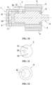
FIG. 10 is a section view of an optical concentration testing device according to anembodiment 4; -
FIG. 11 is a side view of a bubble isolation shield according to theembodiment 4; and -
FIG. 12 is a side view of a sensor body according to theembodiment 4. - In
FIGS. 1 to 12 : - 1: Outer cover; 11: Convection hole; 12: First exhaust hole
- 2: Bubble isolation shield; 21: First separating plate; 22: Second separating plate; 23: Liquid intake hole; 24: Second exhaust hole
- 3: Middle fixing frame; 4: Upper fixing support; 5: Lower fixing support; 6: Fixing ring; 7: Air hole baffle plate;
- 8: Sensor body; 81: Testing gap.
- The technical solutions of the present invention are described hereinafter through embodiments in conjunction with the accompanying drawings.
- As shown in
FIG. 1 to FIG. 3 , an optical concentration sensor protective casing includes anouter cover 1 and abubble isolation shield 2. Thebubble isolation shield 2 is embedded on an inner side of theouter cover 1. The optical concentration sensor protective casing further includes amiddle fixing frame 3, anupper fixing support 4, alower fixing support 5 and a fixing ring 6. Theouter cover 1 and thebubble isolation shield 2 are mounted at one end of themiddle fixing frame 3, the fixing ring 6 is mounted at the other end of themiddle fixing frame 3, and theupper fixing support 4 and thelower fixing support 5 are nested on the outer sides of themiddle fixing frame 3. Thebubble isolation shield 2 and the inner space of themiddle fixing frame 3 form a testing section for a solution to be tested. - The
outer cover 1 is provided with one or more convection holes 11 and thebubble isolation shield 2 is provided with aliquid intake hole 23. An obstacle is disposed between the convection holes 11 and theliquid intake hole 23, and a solution to be tested bypasses the obstacle from the convection holes 11 to theliquid intake hole 23. In the present embodiment, theouter cover 1 is provided with two convection holes 11. The obstacle includes two separating plates. Theliquid intake hole 23 and the two separating plates are disposed on thebubble isolation shield 2, theliquid intake hole 23 is disposed between the two separating plates, and the twoconvection holes 11 are disposed on respective outer sides of the two separating plates. In other embodiments, the separating plates may be disposed on the inner wall of theouter cover 1. - The
outer cover 1 has an open end and a closed end, and the convection holes 11 are disposed on the periphery of the closed end of theouter cover 1. Thebubble isolation shield 2 has an open end and a closed end, the obstacle and theliquid intake hole 23 are both disposed at the closed end of thebubble isolation shield 2, and a bubble separating cavity is formed between the closed end of thebubble isolation shield 2 and the closed end of theouter cover 1. - The two
convection holes 11 may be provided to enable the effective convection between the inner side and the outer side of theouter cover 1, so that the solution to be tested may quickly enter the bubble separating cavity within theouter cover 1. The two separating plates are disposed, and theliquid intake hole 23 is disposed between the two separating plates, so that the solution to be tested needs to bypass the separating plates to reach theliquid intake hole 23, thereby effectively separating bubbles from the liquid of the solution to be tested and ensuring that the solution to be tested entering the testing section is free of bubbles. The twoconvection holes 11 are disposed on respective outer sides of the two separating plates, so that the separating plates may effectively space out the convection holes 11 and theliquid intake hole 23, thereby more effectively separating bubbles from the liquid of the solution to be tested. - In the present embodiment, the two separating plates are arranged in a splayed pattern. The separating plates may be disposed on a slant, so that bubbles in the solution to be tested may float up and be discharged easily along the separating plates. The two separating plates include a
first separating plate 21 and asecond separating plate 22, theliquid intake hole 23 is located at an end where a distance between thefirst separating plate 21 and thesecond separating plate 22 is larger, and theliquid intake hole 23 abuts thesecond separating plate 22. In the working state, thefirst separating plate 21 may be located above thesecond separating plate 22. In the solution, theliquid intake hole 23 abuts thesecond separating plate 22, that is, theliquid intake hole 23 is disposed at a relatively lower position, to prevent bubbles in the solution to be tested from entering the testing section through theliquid intake hole 23. - The
outer cover 1 is made of lightproof materials. Thebubble isolation shield 2 is made of lightproof elastic materials. Thebubble isolation shield 2 may be made of elastic materials, so that thebubble isolation shield 2 may buffer the acting force of the solution to be tested due to icing, so as to avoid the damages to the product caused by the acting force of the solution to be tested due to icing. In the present embodiment, thebubble isolation shield 2 is made of rubber. - The
outer cover 1 is provided with afirst exhaust hole 12 and thebubble isolation shield 2 is provided with asecond exhaust hole 24. Thefirst exhaust hole 12 and thesecond exhaust hole 24 intercommunicate. Thefirst exhaust hole 12 and thesecond exhaust hole 24, which intercommunicate, may be provided for cross-ventilation between the testing section and the outside, thereby ensuring that the solution to be tested may enter the testing section. In the present embodiment, the central axis of thefirst exhaust hole 12 and the central axis of thesecond exhaust hole 24 are a same straight line. - The optical concentration sensor protective casing further includes an air
hole baffle plate 7. The airhole baffle plate 7 covers thefirst exhaust hole 12 and an interstice exists between the airhole baffle plate 7 and thefirst exhaust hole 12. The airhole baffle plate 7 may be disposed on the outer side of thefirst exhaust hole 12, so as to prevent the solution to be tested from directly entering the testing section through thefirst exhaust hole 12 and prevent such pollutants as dust from entering the testing section through thefirst exhaust hole 12 and affecting the precision of the testing result, thereby ensuring the reliability of the testing result. In the present embodiment, the airhole baffle plate 7 is secured to theupper fixing support 4. - An optical concentration testing device includes the above-mentioned optical concentration sensor protective casing and a
sensor body 8. Thesensor body 8 is mounted in the interior of the optical concentration sensor protective casing, thesensor body 8 is provided with atesting gap 81, and thetesting gap 81 opens in the horizontal direction. Thetesting gap 81 is disposed on the horizontal side wall of thesensor body 8, so that bubbles in the solution to be tested may float up and be discharged easily along thetesting gap 81 and thus be eliminated, thereby improving the precision of the testing result. In the present embodiment, thesensor body 8 is mounted within themiddle fixing frame 3. Thetesting gap 81 is V-shaped. Thetesting gap 81 of thesensor body 8 may open in the horizontal direction and the side walls of thetesting gap 81 slant. In this way, if bubbles in the solution to be tested are not eliminated, the remaining bubbles will float up along the side walls of thetesting gap 81 and be discharged from the second exhaust hole, thereby eliminating bubbles in the solution to be tested. - In a testing process, the solution to be tested may enter the bubble separating cavity through the convection holes 11; the solution to be tested in the bubble separating cavity is blocked by the separating plates and is forced to change the flow direction of the solution to be tested instead of directly entering the
liquid intake hole 23; after the solution to be tested flows to the ends between the separating plates along the extending direction of the separating plates, the solution to be tested is no longer blocked by the separating plates and flows towards theliquid intake hole 23. Because of the small density of bubbles, the doped bubbles in the solution to be tested float up and are discharged from the solution to be tested. After bubbles are eliminated, the solution to be tested enters the testing section through theliquid intake hole 23 and the concentration of the solution to be tested is tested by thesensor body 8. - As shown in
FIG. 4 to FIG. 6 , an optical concentration sensor protective casing includes anouter cover 1 and abubble isolation shield 2. Thebubble isolation shield 2 is embedded on an inner side of theouter cover 1. The optical concentration sensor protective casing further includes amiddle fixing frame 3, anupper fixing support 4, alower fixing support 5 and a fixing ring 6. Theouter cover 1 and thebubble isolation shield 2 are mounted at one end of themiddle fixing frame 3, the fixing ring 6 is mounted at the other end of themiddle fixing frame 3, and theupper fixing support 4 and thelower fixing support 5 are nested on the outer sides of themiddle fixing frame 3. Thebubble isolation shield 2 and the inner space of themiddle fixing frame 3 form a testing section for a solution to be tested. - The
outer cover 1 is provided with one or more convection holes 11 and thebubble isolation shield 2 is provided with aliquid intake hole 23. An obstacle is disposed between the convection holes 11 and theliquid intake hole 23, and a solution to be tested bypasses the obstacle from the convection holes 11 to theliquid intake hole 23. In the present embodiment, theouter cover 1 is provided with two convection holes 11. The obstacle includes two separating plates. Theliquid intake hole 23 and the two separating plates are disposed on thebubble isolation shield 2, theliquid intake hole 23 is disposed between the two separating plates, and the twoconvection holes 11 are disposed on respective outer sides of the two separating plates. In other embodiments, the separating plates may be disposed on the inner wall of theouter cover 1. - The
outer cover 1 has an open end and a closed end, and the convection holes 11 are disposed on the periphery of the closed end of theouter cover 1. Thebubble isolation shield 2 has an open end and a closed end, the obstacle and theliquid intake hole 23 are both disposed at the closed end of thebubble isolation shield 2, and a bubble separating cavity is formed between the closed end of thebubble isolation shield 2 and the closed end of theouter cover 1. - The two
convection holes 11 may be provided, to enable the effective convection between the inner side and the outer side of theouter cover 1, so that the solution to be tested may quickly enter the bubble separating cavity within theouter cover 1. The two separating plates are disposed, and theliquid intake hole 23 is disposed between the two separating plates, so that the solution to be tested needs to bypass the separating plates to reach theliquid intake hole 23, thereby effectively separating bubbles from the liquid of the solution to be tested and ensuring that the solution to be tested entering the testing section is free of bubbles. The twoconvection holes 11 are disposed on respective outer sides of the two separating plates, so that the separating plates may effectively space out the convection holes 11 and theliquid intake hole 23, thereby more effectively separating bubbles from the liquid of the solution to be tested. - In the present embodiment, the two separating plates are spaced in parallel, the two separating plates include a
first separating plate 21 and asecond separating plate 22, and the distance between theliquid intake hole 23 and thefirst separating plate 21 is equal to the distance between theliquid intake hole 23 and thesecond separating plate 22. - The
outer cover 1 is made of lightproof materials. Thebubble isolation shield 2 is made of lightproof elastic materials. Thebubble isolation shield 2 may be made of elastic materials so that thebubble isolation shield 2 may buffer the acting force of the solution to be tested due to icing to, so as avoid the damages to the product caused by the acting force of the solution to be tested due to icing. In the present embodiment, thebubble isolation shield 2 is made of rubber. - The
outer cover 1 is provided with afirst exhaust hole 12 and thebubble isolation shield 2 is provided with asecond exhaust hole 24. Thefirst exhaust hole 12 and thesecond exhaust hole 24 are interconnected with each other. Thefirst exhaust hole 12 and thesecond exhaust hole 24 interconnected with each other may be provided for cross-ventilation between the testing section and the outside, thereby ensuring that the solution to be tested may enter the testing section. In the present embodiment, thefirst exhaust hole 12 and thesecond exhaust hole 24 are staggered and thefirst exhaust hole 12 is connected to thesecond exhaust hole 24 via a pipe. - The optical concentration sensor protective casing further includes an air
hole baffle plate 7. The airhole baffle plate 7 covers thefirst exhaust hole 12 and an interstice exists between the airhole baffle plate 7 and thefirst exhaust hole 12. The airhole baffle plate 7 may be disposed on the outer side of thefirst exhaust hole 12, so as to prevent the solution to be tested from directly entering the testing section through thefirst exhaust hole 12 and prevent such pollutants as dust from entering the testing section through thefirst exhaust hole 12 and affecting the precision of the testing result, thereby ensuring the reliability of the testing result. In the present embodiment, the airhole baffle plate 7 is secured to themiddle fixing frame 3. - An optical concentration testing device includes the above-mentioned optical concentration sensor protective casing and a
sensor body 8. Thesensor body 8 is mounted in the interior of the optical concentration sensor protective casing, thesensor body 8 is provided with atesting gap 81, and thetesting gap 81 opens in the horizontal direction. Thetesting gap 81 is disposed on the horizontal side wall of thesensor body 8 so that bubbles in the solution to be tested may float up and be discharged easily along thetesting gap 81 and thus be eliminated, thereby improving the precision of the testing result. In the present embodiment, thesensor body 8 is mounted within themiddle fixing frame 3. Thetesting gap 81 is semi-circular. Thetesting gap 81 of thesensor body 8 may open in the horizontal direction and the side walls of thetesting gap 81 slant. In this way, if bubbles in the solution to be tested are not eliminated, the remaining bubbles will float up along the side walls of thetesting gap 81 and be discharged from the second exhaust hole, thereby eliminating bubbles in the solution to be tested. - In a testing process, the solution to be tested may enter the bubble separating cavity through the convection holes 11; the solution to be tested in the bubble separating cavity is blocked by the separating plates and is forced to change the flow direction of the solution to be tested instead of directly entering the
liquid intake hole 23; after the solution to be tested flows to the ends between the separating plates along the extending direction of the separating plates, the solution to be tested is no longer locked by the separating plates and flows towards theliquid intake hole 23. Because of the small density of bubbles, the doped bubbles in the solution to be tested float up and are discharged from the solution to be tested. After bubbles are eliminated, the solution to be tested enters the testing section through theliquid intake hole 23 and the concentration of the solution to be tested is tested by thesensor body 8. - As shown in
FIG. 7 to FIG. 9 , an optical concentration sensor protective casing includes anouter cover 1 and abubble isolation shield 2. Thebubble isolation shield 2 is embedded on an inner side of theouter cover 1. The optical concentration sensor protective casing further includes amiddle fixing frame 3, anupper fixing support 4, alower fixing support 5 and a fixing ring 6. Theouter cover 1 and thebubble isolation shield 2 are mounted at one end of themiddle fixing frame 3, the fixing ring 6 is mounted at the other end of themiddle fixing frame 3, and theupper fixing support 4 and thelower fixing support 5 are nested on the outer sides of themiddle fixing frame 3. The inner space of thebubble isolation shield 2 and the inner space of themiddle fixing frame 3 form a testing section for a solution to be tested. - The
outer cover 1 is provided with one or more convection holes 11 and thebubble isolation shield 2 is provided with aliquid intake hole 23. An obstacle is disposed between the convection holes 11 and theliquid intake hole 23, and a solution to be tested bypasses the obstacle from the convection holes 11 to theliquid intake hole 23. In the present embodiment, theouter cover 1 is provided with two convection holes 11. The obstacle includes two separating plates. Theliquid intake hole 23 and the two separating plates are disposed on thebubble isolation shield 2, theliquid intake hole 23 is disposed between the two separating plates, and the twoconvection holes 11 are disposed on respective outer sides of the two separating plates. In other embodiments, the separating plates may be disposed on the inner wall of theouter cover 1. - The
outer cover 1 has an open end and a closed end, and the convection holes 11 are disposed on the periphery of the closed end of theouter cover 1. Thebubble isolation shield 2 has an open end and a closed end, the obstacle and theliquid intake hole 23 are both disposed at the closed end of thebubble isolation shield 2, and a bubble separating cavity is formed between the closed end of thebubble isolation shield 2 and the closed end of theouter cover 1. - The two
convection holes 11 may be provided, to enable the effective convection between the inner side and the outer side of theouter cover 1 so that the solution to be tested may quickly enter the bubble separating cavity within theouter cover 1. The two separating plates are disposed, and theliquid intake hole 23 is disposed between the two separating plates, so that the solution to be tested needs to bypass the separating plates to reach theliquid intake hole 23, thereby effectively separating bubbles from the liquid of the solution to be tested and ensuring that the solution to be tested entering the testing section is free of bubbles. The twoconvection holes 11 are disposed on respective outer sides of the two separating plates so that the separating plates may effectively space out the convection holes 11 and theliquid intake hole 23, thereby more effectively separating bubbles from the liquid of the solution to be tested. - In the present embodiment, the two separating plates are spaced in parallel, the two separating plates include a
first separating plate 21 and asecond separating plate 22, and theliquid intake hole 23 abuts thesecond separating plate 22, that is, the distance between theliquid intake hole 23 and thefirst separating plate 21 is larger than the distance between theliquid intake hole 23 and thesecond separating plate 22. In the working state, thefirst separating plate 21 may be located above thesecond separating plate 22. In the solution, theliquid intake hole 23 abuts thesecond separating plate 22, that is, theliquid intake hole 23 is disposed at a relatively lower position, to prevent bubbles in the solution to be tested from entering the testing section through theliquid intake hole 23. - The
outer cover 1 is made of lightproof materials. Thebubble isolation shield 2 is made of lightproof elastic materials. Thebubble isolation shield 2 may be made of elastic materials so that thebubble isolation shield 2 may buffer the acting force of the solution to be tested due to icing, so as to avoid the damages to the product caused by the acting force of the solution to be tested due to icing, In the present embodiment, thebubble isolation shield 2 is made of rubber. - The
outer cover 1 is provided with afirst exhaust hole 12 and thebubble isolation shield 2 is provided with asecond exhaust hole 24. Thefirst exhaust hole 12 and the second exhaust hole 24intercommunicate. Thefirst exhaust hole 12 and thesecond exhaust hole 24, which intercommunicate, may be provided for cross-ventilation between the testing section and the outside, thereby ensuring that the solution to be tested may enter the testing section. In the present embodiment, the central axis of thefirst exhaust hole 12 and the central axis of thesecond exhaust hole 24 are a same straight line. - The optical concentration sensor protective casing further includes an air
hole baffle plate 7. The airhole baffle plate 7 covers thefirst exhaust hole 12 and an interstice exists between the airhole baffle plate 7 and thefirst exhaust hole 12. The airhole baffle plate 7 may be disposed on the outer side of thefirst exhaust hole 12, so as to prevent the solution to be tested from directly entering the testing section through thefirst exhaust hole 12 and prevent such pollutants as dust from entering the testing section through thefirst exhaust hole 12 and affecting the precision of the testing result, thereby ensuring the reliability of the testing result. In the present embodiment, the airhole baffle plate 7 is secured to theouter cover 1. - An optical concentration testing device includes the above-mentioned optical concentration sensor protective casing and a
sensor body 8. Thesensor body 8 is mounted in the interior of the optical concentration sensor protective casing, thesensor body 8 is provided with atesting gap 81, and thetesting gap 81 opens in the horizontal direction. Thetesting gap 81 is disposed on the horizontal side wall of thesensor body 8, so that bubbles in the solution to be tested may float up and be discharged easily along thetesting gap 81 and thus be eliminated, thereby improving the precision of the testing result. In the present embodiment, thesensor body 8 is mounted within themiddle fixing frame 3. Thetesting gap 81 is trapezoidal. Thetesting gap 81 of thesensor body 8 may open in the horizontal direction and the side walls of thetesting gap 81 slant. In this way, if bubbles in the solution to be tested are not eliminated, the remaining bubbles will float up along the side walls of thetesting gap 81 and be discharged from the second exhaust hole, thereby eliminating bubbles in the solution to be tested. - In a testing process, the solution to be tested may enter the bubble separating cavity through the convection holes 11; the solution to be tested in the bubble separating cavity is blocked by the separating plates and is forced to change the flow direction of the solution to be tested instead of directly entering the
liquid intake hole 23; after the solution to be tested flows to the ends between the separating plates along the extending direction of the separating plates, the solution to be tested is no longer blocked by the separating plates and flows towards theliquid intake hole 23. Because of the small density of bubbles, the doped bubbles in the solution to be tested float up and are discharged from the solution to be tested. After bubbles are eliminated, the solution to be tested enters the testing section through theliquid intake hole 23 and the concentration of the solution to be tested is tested by thesensor body 8. - As shown in
FIG. 10 to FIG. 12 , an optical concentration sensor protective casing includes anouter cover 1 and abubble isolation shield 2. Thebubble isolation shield 2 is embedded on an inner side of theouter cover 1. The optical concentration sensor protective casing further includes amiddle fixing frame 3, anupper fixing support 4, alower fixing support 5 and a fixing ring 6. Theouter cover 1 and thebubble isolation shield 2 are mounted at one end of themiddle fixing frame 3, the fixing ring 6 is mounted at the other end of themiddle fixing frame 3, and theupper fixing support 4 and thelower fixing support 5 are nested on the outer sides of themiddle fixing frame 3, Thebubble isolation shield 2 and the inner space of themiddle fixing frame 3 form a testing section for a solution to be tested. - The
outer cover 1 is provided with one or more convection holes 11 and thebubble isolation shield 2 is provided with aliquid intake hole 23. An obstacle is disposed between the convection holes 11 and theliquid intake hole 23, and a solution to be tested bypasses the obstacle from the convection holes 11 to theliquid intake hole 23. In the present embodiment, theouter cover 1 is provided with two convection holes 11. The obstacle includes two separating plates. Theliquid intake hole 23 and the two separating plates are disposed on thebubble isolation shield 2, theliquid intake hole 23 is disposed between the two separating plates, and the twoconvection holes 11 are disposed on respective outer sides of the two separating plates. In other embodiments, the separating plates may be disposed on the inner wall of theouter cover 1. - The
outer cover 1 has an open end and a closed end, and the convection holes 11 are disposed on the periphery of the closed end of theouter cover 1. Thebubble isolation shield 2 has an open end and a closed end, the obstacle and theliquid intake hole 23 are both disposed at the closed end of thebubble isolation shield 2, and a bubble separating cavity is formed between the closed end of thebubble isolation shield 2 and the closed end of theouter cover 1. - The two
convection holes 11 may be provided to enable the effective convection between the inner side and the outer side of theouter cover 1, so that the solution to be tested may quickly enter the bubble separating cavity within theouter cover 1. The two separating plates are disposed, and theliquid intake hole 23 is disposed between the two separating plates, so that the solution to be tested needs to bypass the separating plates to reach theliquid intake hole 23, thereby effectively separating bubbles from the liquid of the solution to be tested and ensuring that the solution to be tested entering the testing section is free of bubbles. The twoconvection holes 11 are disposed on respective outer sides of the two separating plates, so that the separating plates may effectively space out the convection holes 11 and theliquid intake hole 23, thereby more effectively separating bubbles from the liquid of the solution to be tested. - In the present embodiment, the two separating plates are arranged in a splayed pattern. The separating plates may be disposed on a slant so that bubbles in the solution to be tested may float up and be discharged easily along the separating plates. The two separating plates include a
first separating plate 21 and asecond separating plate 22, theliquid intake hole 23 is located at an end where a distance between thefirst separating plate 21 and thesecond separating plate 22 is larger, and the distance between theliquid intake hole 23 and thefirst separating plate 21 is equal to the distance between theliquid intake hole 23 and thesecond separating plate 22. - The
outer cover 1 is made of lightproof materials. Thebubble isolation shield 2 is made of lightproof elastic materials. Thebubble isolation shield 2 may be made of elastic materials, so that thebubble isolation shield 2 may buffer the acting force of the solution to be tested due to icing, so as to avoid the damages to the product caused by the acting force of the solution to be tested due to icing. In the present embodiment, thebubble isolation shield 2 is made of rubber. - The
outer cover 1 is provided with afirst exhaust hole 12 and thebubble isolation shield 2 is provided with asecond exhaust hole 24. Thefirst exhaust hole 12 and thesecond exhaust hole 24 intercommunicate. Thefirst exhaust hole 12 and thesecond exhaust hole 24, which intercommunicate, may be provided for cross-ventilation between the testing section and the outside, thereby ensuring that the solution to be tested may enter the testing section. In the present embodiment, the central axis of thefirst exhaust hole 12 and the central axis of thesecond exhaust hole 24 are a same straight line. - The optical concentration sensor protective casing further includes an air
hole baffle plate 7. The airhole baffle plate 7 covers thefirst exhaust hole 12 and an interstice exists between the airhole baffle plate 7 and thefirst exhaust hole 12. The airhole baffle plate 7 may be disposed on the outer side of thefirst exhaust hole 12, so as to prevent the solution to be tested from directly entering the testing section through thefirst exhaust hole 12 and prevent such pollutants as dust from entering the testing section through thefirst exhaust hole 12 and affecting the precision of the testing result, thereby ensuring the reliability of the testing result. In the present embodiment, the airhole baffle plate 7 is secured to theupper fixing support 4. - An optical concentration testing device includes the above-mentioned optical concentration sensor protective casing and a
sensor body 8. Thesensor body 8 is mounted in the interior of the optical concentration sensor protective casing, thesensor body 8 is provided with atesting gap 81, and thetesting gap 81 opens in the horizontal direction. Thetesting gap 81 is disposed on the horizontal side wall of thesensor body 8, so that bubbles in the solution to be tested may float up and be discharged easily along thetesting gap 81 and thus be eliminated, thereby improving the precision of the testing result. In the present embodiment, thesensor body 8 is mounted within themiddle fixing frame 3. Thetesting gap 81 is V-shaped. Thetesting gap 81 of thesensor body 8 may open in the horizontal direction and the side walls of thetesting gap 81 slant. In this way, if bubbles in the solution to be tested are not eliminated, the remaining bubbles will float up along the side walls of thetesting gap 81 and be discharged from the second exhaust hole, thereby eliminating bubbles in the solution to be tested. - In a testing process, the solution to be tested may enter the bubble separating cavity through the convection holes 11; the solution to be tested in the bubble separating cavity is blocked by the separating plates and is forced to change the flow direction of the solution to be tested instead of directly entering the
liquid intake hole 23; after the solution to be tested flows to the end between the separating plates along the extending direction of the separating plates, the solution to be tested is on longer blocked by the separating plates and flows towards theliquid intake hole 23. Because of the small density of bubbles, the doped bubbles in the solution to be tested float up and are discharged from the solution to be tested. After bubbles are eliminated, the solution to be tested enters the testing section through theliquid intake hole 23 and the concentration of the solution to be tested is tested by thesensor body 8. - The terms "first" and "second" in the specification are only used for descriptive purposes and have no special meanings.
- It is to be noted that the above technical solutions are merely embodiments of the present invention and, within the technical scope disclosed by the present invention, any change or substitution easily conceivable to those skilled in the art should fall within the protection scope of the present invention.
- The present application provides an optical concentration sensor protective casing. The optical concentration sensor protective casing includes an outer cover and a bubble isolation shield. The bubble isolation shield is embedded on the inner side of the outer cover. The outer cover is provided with convection holes. The bubble isolation shield is provided with a liquid intake hole. The present application further provides an optical concentration testing device including the protective casing. With the protective casing provided to protect a sensor body, on the one hand, the sensor body is prevented from being damaged due to collision or squeeze to the sensor body, thereby prolonging the service life of the sensor body; on the other hand, a solution to be tested inside the protective casing tends to be still, thereby improving the precision of the testing result. In addition, an air hole baffle plate is disposed on the outer side of the outer cover to prevent the solution to be tested from directly entering a testing section in a pouring process and prevent such pollutants as dust that affect the precision of the testing result from entering the testing section, thereby ensuring the reliability of the testing result.
Claims (6)
- An optical concentration testing device comprising an optical concentration sensor protective casing, wherein,said optical concentration sensor protective casing comprises an outer cover (1), and a bubble isolation shield (2) embedded on an inner side of the outer cover (1);the outer cover (1) is provided with a convection hole (11); andthe bubble isolation shield (2) is provided with a liquid intake hole (23);said optical concentration sensor protective casing further comprises a middle fixing frame (3) and an air hole baffle plate (7),wherein the outer cover (1) is provided with a first exhaust hole (12), the air hole baffle plate (7) covers the first exhaust hole (12), and an interstice exists between the air hole baffle plate (7) and the first exhaust hole (12),wherein the bubble isolation shield (2) is provided with a second exhaust hole (24), the first exhaust hole (12) and the second exhaust hole (24) intercommunicate,wherein the outer cover (1) and the bubble isolation shield (2) are mounted at one end of the middle fixing frame (3), the bubble isolation shield (2) and an inner space of the middle fixing frame (3) form a testing section for a solution to be tested,said optical concentration testing device further comprises a sensor body (8) configured to test the concentration of the solution and mounted in the interior of the optical concentration sensor protective casing, andcharacterized in that, the sensor body (8) is provided with a testing gap (81) opening in a horizontal direction and disposed on a horizontal side wall of the sensor body (8), the sensor body (8) is mounted within the middle fixing frame (3), and the testing gap (81) has slanted side walls, so that if bubbles in the solution to be tested are not eliminated and enter into the testing section, the remaining bubbles in the testing section will float up along the slanted side walls of the testing gap (81) and be discharged from the second exhaust hole (24).
- The optical concentration testing device according to claim 1, wherein an obstacle is disposed between the convection hole (11) and the liquid intake hole (23) and the solution to be tested bypasses the obstacle from the convection hole (11) to the liquid intake hole (23).
- The optical concentration testing device according to claim 2, wherein the outer cover (1) is provided with two convection holes (11), the obstacle comprises two separating plates, the liquid intake hole (23) is disposed between the two separating plates, and the two convection holes (11) are disposed on respective outer sides of the two separating plates.
- The optical concentration testing device according to claim 3, wherein the two separating plates are arranged in a splayed pattern.
- The optical concentration testing device according to claim 4, wherein the two separating plates comprise a first separating plate (21) and a second separating plate (22), the liquid intake hole (23) is located between the first separating plate (21) and the second separating plate (22) and at an end where a distance between the first separating plate (21) and the second separating plate (22) is larger, and the liquid intake hole (23) abuts the second separating plate.
- The optical concentration testing device according to any one of claims 1 to 5, wherein the bubble isolation shield (2) is made of elastic materials.
Applications Claiming Priority (1)
| Application Number | Priority Date | Filing Date | Title |
|---|---|---|---|
| PCT/CN2016/074697 WO2017143590A1 (en) | 2016-02-26 | 2016-02-26 | Optical density sensor protective casing and optical density testing device |
Publications (3)
| Publication Number | Publication Date |
|---|---|
| EP3428617A1 EP3428617A1 (en) | 2019-01-16 |
| EP3428617A4 EP3428617A4 (en) | 2019-11-20 |
| EP3428617B1 true EP3428617B1 (en) | 2024-10-16 |
Family
ID=59684928
Family Applications (1)
| Application Number | Title | Priority Date | Filing Date |
|---|---|---|---|
| EP16891044.6A Active EP3428617B1 (en) | 2016-02-26 | 2016-02-26 | Optical density sensor protective casing and optical density testing device |
Country Status (4)
| Country | Link |
|---|---|
| US (1) | US10670516B2 (en) |
| EP (1) | EP3428617B1 (en) |
| KR (1) | KR102106564B1 (en) |
| WO (1) | WO2017143590A1 (en) |
Families Citing this family (5)
| Publication number | Priority date | Publication date | Assignee | Title |
|---|---|---|---|---|
| CN113075153B (en) * | 2021-03-31 | 2021-12-24 | 浙江焜腾红外科技有限公司 | Imaging sensor for remote infrared gas and detection mechanism thereof |
| CN114034767B (en) * | 2021-12-01 | 2025-07-25 | 广东正扬传感科技股份有限公司 | Solution detection sensor |
| CN114460008B (en) * | 2022-02-16 | 2023-11-21 | 西南石油大学 | Wellhead foam detection device and method |
| CN115616091A (en) * | 2022-08-23 | 2023-01-17 | 南昌攀藤科技有限公司 | Ultrasonic probe |
| WO2024054630A1 (en) * | 2022-09-08 | 2024-03-14 | Shaw Development, Llc | Diesel exhaust fluid sensor adapter for fluid aeration mitigation |
Family Cites Families (11)
| Publication number | Priority date | Publication date | Assignee | Title |
|---|---|---|---|---|
| DK117739B (en) * | 1968-07-10 | 1970-05-25 | Inst Produktudvikling | Bulb-separating flow-through cuvette. |
| SE370454B (en) * | 1970-01-30 | 1974-10-14 | Nordstjernan Rederi Ab | |
| US3849002A (en) | 1973-05-11 | 1974-11-19 | Hach Chemical Co | Method and apparatus for eliminating air during fluid turbidity measurement |
| US5831727A (en) * | 1997-04-29 | 1998-11-03 | Hach Company | Bubble elimination from liquid |
| JP5221053B2 (en) * | 2007-04-09 | 2013-06-26 | 株式会社日本自動車部品総合研究所 | Urea concentration detector |
| US8248611B2 (en) * | 2010-03-31 | 2012-08-21 | Ecolab Usa Inc. | Handheld optical measuring device and method of use |
| CN202110139U (en) * | 2011-05-31 | 2012-01-11 | 中国农业大学 | Underwater Optical Dissolved Oxygen Sensor |
| US8663562B2 (en) * | 2011-09-13 | 2014-03-04 | Sabic Innovative Plastics Ip B.V. | Flow cell for measuring electromagnetic radiation absorption spectra in a continuously flowing immiscible liquid(s) or liquids with entrained gas phases |
| KR101221880B1 (en) * | 2012-04-30 | 2013-01-16 | 주식회사 과학기술분석센타 | Protective cap having turbidity mesuring container for water quailty sensor and apparatus having turbidity mesuring container for water quailty sensor |
| KR101732039B1 (en) * | 2014-04-18 | 2017-06-05 | 주식회사 과학기술분석센타 | Measuring apparatus of water quality for stable inlet and outlet seawater |
| CN204214768U (en) * | 2014-11-24 | 2015-03-18 | 安徽芯核防务装备技术股份有限公司 | A kind of froth breaking shade for turbidity and dissolved oxygen sensor |
-
2016
- 2016-02-26 KR KR1020187027737A patent/KR102106564B1/en active Active
- 2016-02-26 EP EP16891044.6A patent/EP3428617B1/en active Active
- 2016-02-26 US US16/079,702 patent/US10670516B2/en active Active
- 2016-02-26 WO PCT/CN2016/074697 patent/WO2017143590A1/en not_active Ceased
Also Published As
| Publication number | Publication date |
|---|---|
| WO2017143590A1 (en) | 2017-08-31 |
| KR102106564B1 (en) | 2020-05-07 |
| EP3428617A4 (en) | 2019-11-20 |
| US20190072480A1 (en) | 2019-03-07 |
| US10670516B2 (en) | 2020-06-02 |
| EP3428617A1 (en) | 2019-01-16 |
| KR20180116395A (en) | 2018-10-24 |
Similar Documents
| Publication | Publication Date | Title |
|---|---|---|
| US10670516B2 (en) | Optical concentration sensor protective casing and optical concentration testing device | |
| CN105738284B (en) | Protective cover for optical density sensor and optical density testing device | |
| RU2672013C2 (en) | On-board diagnostics system for catalysed substrate | |
| RU2704382C2 (en) | System (embodiments) and method of detecting solid particles | |
| US9038369B2 (en) | Systems and methods for aftertreatment system diagnostics | |
| US9664089B2 (en) | Fault diagnosis method of SCR system and an apparatus thereof | |
| KR101416408B1 (en) | Method and system of determining failure of urea quality sensor | |
| US11136911B2 (en) | Method and device for diagnosis of a particle filter arranged in the exhuast gas system of a petro-operated internal combustion engine | |
| EP3665372B1 (en) | Level sensor assembly. | |
| WO2022105900A1 (en) | Detection device | |
| US9804004B1 (en) | Fluid quality sensor and cover assembly | |
| US9404845B2 (en) | Sensor for detecting the quality of a fluid | |
| ES2886609T3 (en) | Procedure for the control of NOx emissions from a vehicle | |
| CN103046990A (en) | Monitor of ammonia in dosing system | |
| KR101822268B1 (en) | SENSOR FOR SENSING PM-NOx | |
| CN205404384U (en) | Protective cover for optical density sensor and optical density testing device | |
| KR101836282B1 (en) | Exhaust system with differential pressure sensor | |
| US11066975B2 (en) | Method and device for diagnosis of a particle filter arranged in the exhaust gas system of a petrol-operated internal combustion engine | |
| JP2009041415A (en) | Exhaust purification device | |
| CN212483260U (en) | Vehicle exhaust particulate matter detection device and system | |
| JP2004219269A (en) | Light oil identification method, light oil identification device, and light oil identification system | |
| KR101834839B1 (en) | remote control device of exhaust gas pressure control valve for automobile | |
| KR100836406B1 (en) | SC monitoring system | |
| KR20170143132A (en) | Apparatus for diagnosing urea | |
| CN215180022U (en) | Vehicle-mounted diesel engine tail gas detection device |
Legal Events
| Date | Code | Title | Description |
|---|---|---|---|
| STAA | Information on the status of an ep patent application or granted ep patent |
Free format text: STATUS: THE INTERNATIONAL PUBLICATION HAS BEEN MADE |
|
| PUAI | Public reference made under article 153(3) epc to a published international application that has entered the european phase |
Free format text: ORIGINAL CODE: 0009012 |
|
| STAA | Information on the status of an ep patent application or granted ep patent |
Free format text: STATUS: REQUEST FOR EXAMINATION WAS MADE |
|
| 17P | Request for examination filed |
Effective date: 20180907 |
|
| AK | Designated contracting states |
Kind code of ref document: A1 Designated state(s): AL AT BE BG CH CY CZ DE DK EE ES FI FR GB GR HR HU IE IS IT LI LT LU LV MC MK MT NL NO PL PT RO RS SE SI SK SM TR |
|
| AX | Request for extension of the european patent |
Extension state: BA ME |
|
| DAV | Request for validation of the european patent (deleted) | ||
| DAX | Request for extension of the european patent (deleted) | ||
| A4 | Supplementary search report drawn up and despatched |
Effective date: 20191017 |
|
| RIC1 | Information provided on ipc code assigned before grant |
Ipc: B60K 13/04 20060101ALI20191011BHEP Ipc: F01N 3/20 20060101ALI20191011BHEP Ipc: G01N 21/05 20060101ALI20191011BHEP Ipc: G01N 21/01 20060101AFI20191011BHEP |
|
| STAA | Information on the status of an ep patent application or granted ep patent |
Free format text: STATUS: EXAMINATION IS IN PROGRESS |
|
| 17Q | First examination report despatched |
Effective date: 20220621 |
|
| GRAP | Despatch of communication of intention to grant a patent |
Free format text: ORIGINAL CODE: EPIDOSNIGR1 |
|
| STAA | Information on the status of an ep patent application or granted ep patent |
Free format text: STATUS: GRANT OF PATENT IS INTENDED |
|
| INTG | Intention to grant announced |
Effective date: 20240513 |
|
| GRAS | Grant fee paid |
Free format text: ORIGINAL CODE: EPIDOSNIGR3 |
|
| GRAA | (expected) grant |
Free format text: ORIGINAL CODE: 0009210 |
|
| STAA | Information on the status of an ep patent application or granted ep patent |
Free format text: STATUS: THE PATENT HAS BEEN GRANTED |
|
| RAP3 | Party data changed (applicant data changed or rights of an application transferred) |
Owner name: KUS TECHNOLOGY CORPORATION |
|
| AK | Designated contracting states |
Kind code of ref document: B1 Designated state(s): AL AT BE BG CH CY CZ DE DK EE ES FI FR GB GR HR HU IE IS IT LI LT LU LV MC MK MT NL NO PL PT RO RS SE SI SK SM TR |
|
| REG | Reference to a national code |
Ref country code: GB Ref legal event code: FG4D |
|
| REG | Reference to a national code |
Ref country code: CH Ref legal event code: EP |
|
| REG | Reference to a national code |
Ref country code: IE Ref legal event code: FG4D |
|
| REG | Reference to a national code |
Ref country code: DE Ref legal event code: R096 Ref document number: 602016089893 Country of ref document: DE |
|
| REG | Reference to a national code |
Ref country code: LT Ref legal event code: MG9D |
|
| REG | Reference to a national code |
Ref country code: NL Ref legal event code: MP Effective date: 20241016 |
|
| REG | Reference to a national code |
Ref country code: AT Ref legal event code: MK05 Ref document number: 1733281 Country of ref document: AT Kind code of ref document: T Effective date: 20241016 |
|
| PG25 | Lapsed in a contracting state [announced via postgrant information from national office to epo] |
Ref country code: NL Free format text: LAPSE BECAUSE OF FAILURE TO SUBMIT A TRANSLATION OF THE DESCRIPTION OR TO PAY THE FEE WITHIN THE PRESCRIBED TIME-LIMIT Effective date: 20241016 |
|
| PG25 | Lapsed in a contracting state [announced via postgrant information from national office to epo] |
Ref country code: NL Free format text: LAPSE BECAUSE OF FAILURE TO SUBMIT A TRANSLATION OF THE DESCRIPTION OR TO PAY THE FEE WITHIN THE PRESCRIBED TIME-LIMIT Effective date: 20241016 |
|
| PG25 | Lapsed in a contracting state [announced via postgrant information from national office to epo] |
Ref country code: IS Free format text: LAPSE BECAUSE OF FAILURE TO SUBMIT A TRANSLATION OF THE DESCRIPTION OR TO PAY THE FEE WITHIN THE PRESCRIBED TIME-LIMIT Effective date: 20250216 Ref country code: HR Free format text: LAPSE BECAUSE OF FAILURE TO SUBMIT A TRANSLATION OF THE DESCRIPTION OR TO PAY THE FEE WITHIN THE PRESCRIBED TIME-LIMIT Effective date: 20241016 Ref country code: PT Free format text: LAPSE BECAUSE OF FAILURE TO SUBMIT A TRANSLATION OF THE DESCRIPTION OR TO PAY THE FEE WITHIN THE PRESCRIBED TIME-LIMIT Effective date: 20250217 |
|
| PG25 | Lapsed in a contracting state [announced via postgrant information from national office to epo] |
Ref country code: FI Free format text: LAPSE BECAUSE OF FAILURE TO SUBMIT A TRANSLATION OF THE DESCRIPTION OR TO PAY THE FEE WITHIN THE PRESCRIBED TIME-LIMIT Effective date: 20241016 |
|
| PG25 | Lapsed in a contracting state [announced via postgrant information from national office to epo] |
Ref country code: BG Free format text: LAPSE BECAUSE OF FAILURE TO SUBMIT A TRANSLATION OF THE DESCRIPTION OR TO PAY THE FEE WITHIN THE PRESCRIBED TIME-LIMIT Effective date: 20241016 |
|
| PG25 | Lapsed in a contracting state [announced via postgrant information from national office to epo] |
Ref country code: ES Free format text: LAPSE BECAUSE OF FAILURE TO SUBMIT A TRANSLATION OF THE DESCRIPTION OR TO PAY THE FEE WITHIN THE PRESCRIBED TIME-LIMIT Effective date: 20241016 |
|
| PG25 | Lapsed in a contracting state [announced via postgrant information from national office to epo] |
Ref country code: NO Free format text: LAPSE BECAUSE OF FAILURE TO SUBMIT A TRANSLATION OF THE DESCRIPTION OR TO PAY THE FEE WITHIN THE PRESCRIBED TIME-LIMIT Effective date: 20250116 |
|
| PG25 | Lapsed in a contracting state [announced via postgrant information from national office to epo] |
Ref country code: AT Free format text: LAPSE BECAUSE OF FAILURE TO SUBMIT A TRANSLATION OF THE DESCRIPTION OR TO PAY THE FEE WITHIN THE PRESCRIBED TIME-LIMIT Effective date: 20241016 Ref country code: LV Free format text: LAPSE BECAUSE OF FAILURE TO SUBMIT A TRANSLATION OF THE DESCRIPTION OR TO PAY THE FEE WITHIN THE PRESCRIBED TIME-LIMIT Effective date: 20241016 Ref country code: GR Free format text: LAPSE BECAUSE OF FAILURE TO SUBMIT A TRANSLATION OF THE DESCRIPTION OR TO PAY THE FEE WITHIN THE PRESCRIBED TIME-LIMIT Effective date: 20250117 |
|
| PG25 | Lapsed in a contracting state [announced via postgrant information from national office to epo] |
Ref country code: PL Free format text: LAPSE BECAUSE OF FAILURE TO SUBMIT A TRANSLATION OF THE DESCRIPTION OR TO PAY THE FEE WITHIN THE PRESCRIBED TIME-LIMIT Effective date: 20241016 |
|
| PG25 | Lapsed in a contracting state [announced via postgrant information from national office to epo] |
Ref country code: RS Free format text: LAPSE BECAUSE OF FAILURE TO SUBMIT A TRANSLATION OF THE DESCRIPTION OR TO PAY THE FEE WITHIN THE PRESCRIBED TIME-LIMIT Effective date: 20250116 |
|
| PG25 | Lapsed in a contracting state [announced via postgrant information from national office to epo] |
Ref country code: SM Free format text: LAPSE BECAUSE OF FAILURE TO SUBMIT A TRANSLATION OF THE DESCRIPTION OR TO PAY THE FEE WITHIN THE PRESCRIBED TIME-LIMIT Effective date: 20241016 |
|
| PG25 | Lapsed in a contracting state [announced via postgrant information from national office to epo] |
Ref country code: DK Free format text: LAPSE BECAUSE OF FAILURE TO SUBMIT A TRANSLATION OF THE DESCRIPTION OR TO PAY THE FEE WITHIN THE PRESCRIBED TIME-LIMIT Effective date: 20241016 |
|
| REG | Reference to a national code |
Ref country code: DE Ref legal event code: R097 Ref document number: 602016089893 Country of ref document: DE |
|
| PG25 | Lapsed in a contracting state [announced via postgrant information from national office to epo] |
Ref country code: EE Free format text: LAPSE BECAUSE OF FAILURE TO SUBMIT A TRANSLATION OF THE DESCRIPTION OR TO PAY THE FEE WITHIN THE PRESCRIBED TIME-LIMIT Effective date: 20241016 |
|
| PG25 | Lapsed in a contracting state [announced via postgrant information from national office to epo] |
Ref country code: RO Free format text: LAPSE BECAUSE OF FAILURE TO SUBMIT A TRANSLATION OF THE DESCRIPTION OR TO PAY THE FEE WITHIN THE PRESCRIBED TIME-LIMIT Effective date: 20241016 |
|
| PG25 | Lapsed in a contracting state [announced via postgrant information from national office to epo] |
Ref country code: SK Free format text: LAPSE BECAUSE OF FAILURE TO SUBMIT A TRANSLATION OF THE DESCRIPTION OR TO PAY THE FEE WITHIN THE PRESCRIBED TIME-LIMIT Effective date: 20241016 |
|
| PG25 | Lapsed in a contracting state [announced via postgrant information from national office to epo] |
Ref country code: CZ Free format text: LAPSE BECAUSE OF FAILURE TO SUBMIT A TRANSLATION OF THE DESCRIPTION OR TO PAY THE FEE WITHIN THE PRESCRIBED TIME-LIMIT Effective date: 20241016 |
|
| PG25 | Lapsed in a contracting state [announced via postgrant information from national office to epo] |
Ref country code: IT Free format text: LAPSE BECAUSE OF FAILURE TO SUBMIT A TRANSLATION OF THE DESCRIPTION OR TO PAY THE FEE WITHIN THE PRESCRIBED TIME-LIMIT Effective date: 20241016 |
|
| PLBE | No opposition filed within time limit |
Free format text: ORIGINAL CODE: 0009261 |
|
| STAA | Information on the status of an ep patent application or granted ep patent |
Free format text: STATUS: NO OPPOSITION FILED WITHIN TIME LIMIT |
|
| PG25 | Lapsed in a contracting state [announced via postgrant information from national office to epo] |
Ref country code: SE Free format text: LAPSE BECAUSE OF FAILURE TO SUBMIT A TRANSLATION OF THE DESCRIPTION OR TO PAY THE FEE WITHIN THE PRESCRIBED TIME-LIMIT Effective date: 20241016 |
|
| PG25 | Lapsed in a contracting state [announced via postgrant information from national office to epo] |
Ref country code: MC Free format text: LAPSE BECAUSE OF FAILURE TO SUBMIT A TRANSLATION OF THE DESCRIPTION OR TO PAY THE FEE WITHIN THE PRESCRIBED TIME-LIMIT Effective date: 20241016 |
|
| 26N | No opposition filed |
Effective date: 20250717 |
|
| REG | Reference to a national code |
Ref country code: CH Ref legal event code: PL |
|
| PG25 | Lapsed in a contracting state [announced via postgrant information from national office to epo] |
Ref country code: LU Free format text: LAPSE BECAUSE OF NON-PAYMENT OF DUE FEES Effective date: 20250226 |
|
| PG25 | Lapsed in a contracting state [announced via postgrant information from national office to epo] |
Ref country code: CH Free format text: LAPSE BECAUSE OF NON-PAYMENT OF DUE FEES Effective date: 20250228 |
|
| GBPC | Gb: european patent ceased through non-payment of renewal fee |
Effective date: 20250226 |
|
| REG | Reference to a national code |
Ref country code: BE Ref legal event code: MM Effective date: 20250228 |
|
| PG25 | Lapsed in a contracting state [announced via postgrant information from national office to epo] |
Ref country code: GB Free format text: LAPSE BECAUSE OF NON-PAYMENT OF DUE FEES Effective date: 20250226 |
|
| PG25 | Lapsed in a contracting state [announced via postgrant information from national office to epo] |
Ref country code: FR Free format text: LAPSE BECAUSE OF NON-PAYMENT OF DUE FEES Effective date: 20250228 |
|
| PG25 | Lapsed in a contracting state [announced via postgrant information from national office to epo] |
Ref country code: BE Free format text: LAPSE BECAUSE OF NON-PAYMENT OF DUE FEES Effective date: 20250228 |
|
| PG25 | Lapsed in a contracting state [announced via postgrant information from national office to epo] |
Ref country code: IE Free format text: LAPSE BECAUSE OF NON-PAYMENT OF DUE FEES Effective date: 20250226 |
|
| PGFP | Annual fee paid to national office [announced via postgrant information from national office to epo] |
Ref country code: DE Payment date: 20260218 Year of fee payment: 11 |