EP3428577A1 - Système d'assistance au conducteur et procédé - Google Patents
Système d'assistance au conducteur et procédé Download PDFInfo
- Publication number
- EP3428577A1 EP3428577A1 EP17181013.8A EP17181013A EP3428577A1 EP 3428577 A1 EP3428577 A1 EP 3428577A1 EP 17181013 A EP17181013 A EP 17181013A EP 3428577 A1 EP3428577 A1 EP 3428577A1
- Authority
- EP
- European Patent Office
- Prior art keywords
- ego vehicle
- measurement
- static feature
- driver assistance
- location
- Prior art date
- Legal status (The legal status is an assumption and is not a legal conclusion. Google has not performed a legal analysis and makes no representation as to the accuracy of the status listed.)
- Pending
Links
- 238000000034 method Methods 0.000 title claims abstract description 25
- 230000003068 static effect Effects 0.000 claims abstract description 162
- 238000005259 measurement Methods 0.000 claims abstract description 104
- 230000000007 visual effect Effects 0.000 claims abstract description 9
- 230000007704 transition Effects 0.000 claims description 20
- 238000004364 calculation method Methods 0.000 claims description 5
- 238000007670 refining Methods 0.000 claims description 4
- 238000001514 detection method Methods 0.000 abstract description 5
- 238000004891 communication Methods 0.000 description 17
- 238000012545 processing Methods 0.000 description 12
- 230000006870 function Effects 0.000 description 6
- 238000012544 monitoring process Methods 0.000 description 6
- 235000004522 Pentaglottis sempervirens Nutrition 0.000 description 3
- 238000013500 data storage Methods 0.000 description 3
- 230000003044 adaptive effect Effects 0.000 description 2
- 230000008859 change Effects 0.000 description 2
- 230000008569 process Effects 0.000 description 2
- 230000009467 reduction Effects 0.000 description 2
- 238000000926 separation method Methods 0.000 description 2
- 230000003466 anti-cipated effect Effects 0.000 description 1
- 230000006399 behavior Effects 0.000 description 1
- 238000009826 distribution Methods 0.000 description 1
- 230000000694 effects Effects 0.000 description 1
- 238000005516 engineering process Methods 0.000 description 1
- 230000003993 interaction Effects 0.000 description 1
- 238000004519 manufacturing process Methods 0.000 description 1
- 239000003550 marker Substances 0.000 description 1
- 239000011159 matrix material Substances 0.000 description 1
- 230000000116 mitigating effect Effects 0.000 description 1
- 238000012986 modification Methods 0.000 description 1
- 230000004048 modification Effects 0.000 description 1
- 230000003287 optical effect Effects 0.000 description 1
- 230000002265 prevention Effects 0.000 description 1
- 238000003860 storage Methods 0.000 description 1
- 230000009466 transformation Effects 0.000 description 1
Images


Classifications
-
- G—PHYSICS
- G01—MEASURING; TESTING
- G01C—MEASURING DISTANCES, LEVELS OR BEARINGS; SURVEYING; NAVIGATION; GYROSCOPIC INSTRUMENTS; PHOTOGRAMMETRY OR VIDEOGRAMMETRY
- G01C21/00—Navigation; Navigational instruments not provided for in groups G01C1/00 - G01C19/00
- G01C21/10—Navigation; Navigational instruments not provided for in groups G01C1/00 - G01C19/00 by using measurements of speed or acceleration
- G01C21/12—Navigation; Navigational instruments not provided for in groups G01C1/00 - G01C19/00 by using measurements of speed or acceleration executed aboard the object being navigated; Dead reckoning
- G01C21/16—Navigation; Navigational instruments not provided for in groups G01C1/00 - G01C19/00 by using measurements of speed or acceleration executed aboard the object being navigated; Dead reckoning by integrating acceleration or speed, i.e. inertial navigation
- G01C21/165—Navigation; Navigational instruments not provided for in groups G01C1/00 - G01C19/00 by using measurements of speed or acceleration executed aboard the object being navigated; Dead reckoning by integrating acceleration or speed, i.e. inertial navigation combined with non-inertial navigation instruments
- G01C21/1656—Navigation; Navigational instruments not provided for in groups G01C1/00 - G01C19/00 by using measurements of speed or acceleration executed aboard the object being navigated; Dead reckoning by integrating acceleration or speed, i.e. inertial navigation combined with non-inertial navigation instruments with passive imaging devices, e.g. cameras
-
- B—PERFORMING OPERATIONS; TRANSPORTING
- B60—VEHICLES IN GENERAL
- B60W—CONJOINT CONTROL OF VEHICLE SUB-UNITS OF DIFFERENT TYPE OR DIFFERENT FUNCTION; CONTROL SYSTEMS SPECIALLY ADAPTED FOR HYBRID VEHICLES; ROAD VEHICLE DRIVE CONTROL SYSTEMS FOR PURPOSES NOT RELATED TO THE CONTROL OF A PARTICULAR SUB-UNIT
- B60W60/00—Drive control systems specially adapted for autonomous road vehicles
- B60W60/001—Planning or execution of driving tasks
-
- G—PHYSICS
- G01—MEASURING; TESTING
- G01C—MEASURING DISTANCES, LEVELS OR BEARINGS; SURVEYING; NAVIGATION; GYROSCOPIC INSTRUMENTS; PHOTOGRAMMETRY OR VIDEOGRAMMETRY
- G01C21/00—Navigation; Navigational instruments not provided for in groups G01C1/00 - G01C19/00
- G01C21/10—Navigation; Navigational instruments not provided for in groups G01C1/00 - G01C19/00 by using measurements of speed or acceleration
- G01C21/12—Navigation; Navigational instruments not provided for in groups G01C1/00 - G01C19/00 by using measurements of speed or acceleration executed aboard the object being navigated; Dead reckoning
- G01C21/16—Navigation; Navigational instruments not provided for in groups G01C1/00 - G01C19/00 by using measurements of speed or acceleration executed aboard the object being navigated; Dead reckoning by integrating acceleration or speed, i.e. inertial navigation
- G01C21/165—Navigation; Navigational instruments not provided for in groups G01C1/00 - G01C19/00 by using measurements of speed or acceleration executed aboard the object being navigated; Dead reckoning by integrating acceleration or speed, i.e. inertial navigation combined with non-inertial navigation instruments
- G01C21/1652—Navigation; Navigational instruments not provided for in groups G01C1/00 - G01C19/00 by using measurements of speed or acceleration executed aboard the object being navigated; Dead reckoning by integrating acceleration or speed, i.e. inertial navigation combined with non-inertial navigation instruments with ranging devices, e.g. LIDAR or RADAR
-
- G—PHYSICS
- G01—MEASURING; TESTING
- G01C—MEASURING DISTANCES, LEVELS OR BEARINGS; SURVEYING; NAVIGATION; GYROSCOPIC INSTRUMENTS; PHOTOGRAMMETRY OR VIDEOGRAMMETRY
- G01C21/00—Navigation; Navigational instruments not provided for in groups G01C1/00 - G01C19/00
- G01C21/26—Navigation; Navigational instruments not provided for in groups G01C1/00 - G01C19/00 specially adapted for navigation in a road network
- G01C21/28—Navigation; Navigational instruments not provided for in groups G01C1/00 - G01C19/00 specially adapted for navigation in a road network with correlation of data from several navigational instruments
- G01C21/30—Map- or contour-matching
-
- G—PHYSICS
- G01—MEASURING; TESTING
- G01C—MEASURING DISTANCES, LEVELS OR BEARINGS; SURVEYING; NAVIGATION; GYROSCOPIC INSTRUMENTS; PHOTOGRAMMETRY OR VIDEOGRAMMETRY
- G01C21/00—Navigation; Navigational instruments not provided for in groups G01C1/00 - G01C19/00
- G01C21/26—Navigation; Navigational instruments not provided for in groups G01C1/00 - G01C19/00 specially adapted for navigation in a road network
- G01C21/34—Route searching; Route guidance
- G01C21/36—Input/output arrangements for on-board computers
- G01C21/3626—Details of the output of route guidance instructions
- G01C21/3644—Landmark guidance, e.g. using POIs or conspicuous other objects
-
- G—PHYSICS
- G01—MEASURING; TESTING
- G01S—RADIO DIRECTION-FINDING; RADIO NAVIGATION; DETERMINING DISTANCE OR VELOCITY BY USE OF RADIO WAVES; LOCATING OR PRESENCE-DETECTING BY USE OF THE REFLECTION OR RERADIATION OF RADIO WAVES; ANALOGOUS ARRANGEMENTS USING OTHER WAVES
- G01S13/00—Systems using the reflection or reradiation of radio waves, e.g. radar systems; Analogous systems using reflection or reradiation of waves whose nature or wavelength is irrelevant or unspecified
- G01S13/86—Combinations of radar systems with non-radar systems, e.g. sonar, direction finder
- G01S13/867—Combination of radar systems with cameras
-
- G—PHYSICS
- G01—MEASURING; TESTING
- G01S—RADIO DIRECTION-FINDING; RADIO NAVIGATION; DETERMINING DISTANCE OR VELOCITY BY USE OF RADIO WAVES; LOCATING OR PRESENCE-DETECTING BY USE OF THE REFLECTION OR RERADIATION OF RADIO WAVES; ANALOGOUS ARRANGEMENTS USING OTHER WAVES
- G01S13/00—Systems using the reflection or reradiation of radio waves, e.g. radar systems; Analogous systems using reflection or reradiation of waves whose nature or wavelength is irrelevant or unspecified
- G01S13/88—Radar or analogous systems specially adapted for specific applications
- G01S13/93—Radar or analogous systems specially adapted for specific applications for anti-collision purposes
- G01S13/931—Radar or analogous systems specially adapted for specific applications for anti-collision purposes of land vehicles
-
- G—PHYSICS
- G01—MEASURING; TESTING
- G01S—RADIO DIRECTION-FINDING; RADIO NAVIGATION; DETERMINING DISTANCE OR VELOCITY BY USE OF RADIO WAVES; LOCATING OR PRESENCE-DETECTING BY USE OF THE REFLECTION OR RERADIATION OF RADIO WAVES; ANALOGOUS ARRANGEMENTS USING OTHER WAVES
- G01S19/00—Satellite radio beacon positioning systems; Determining position, velocity or attitude using signals transmitted by such systems
- G01S19/38—Determining a navigation solution using signals transmitted by a satellite radio beacon positioning system
- G01S19/39—Determining a navigation solution using signals transmitted by a satellite radio beacon positioning system the satellite radio beacon positioning system transmitting time-stamped messages, e.g. GPS [Global Positioning System], GLONASS [Global Orbiting Navigation Satellite System] or GALILEO
- G01S19/42—Determining position
- G01S19/48—Determining position by combining or switching between position solutions derived from the satellite radio beacon positioning system and position solutions derived from a further system
-
- G—PHYSICS
- G05—CONTROLLING; REGULATING
- G05D—SYSTEMS FOR CONTROLLING OR REGULATING NON-ELECTRIC VARIABLES
- G05D1/00—Control of position, course or altitude of land, water, air, or space vehicles, e.g. automatic pilot
- G05D1/02—Control of position or course in two dimensions
- G05D1/021—Control of position or course in two dimensions specially adapted to land vehicles
- G05D1/0231—Control of position or course in two dimensions specially adapted to land vehicles using optical position detecting means
-
- G—PHYSICS
- G06—COMPUTING; CALCULATING OR COUNTING
- G06V—IMAGE OR VIDEO RECOGNITION OR UNDERSTANDING
- G06V20/00—Scenes; Scene-specific elements
- G06V20/50—Context or environment of the image
- G06V20/56—Context or environment of the image exterior to a vehicle by using sensors mounted on the vehicle
-
- B—PERFORMING OPERATIONS; TRANSPORTING
- B60—VEHICLES IN GENERAL
- B60W—CONJOINT CONTROL OF VEHICLE SUB-UNITS OF DIFFERENT TYPE OR DIFFERENT FUNCTION; CONTROL SYSTEMS SPECIALLY ADAPTED FOR HYBRID VEHICLES; ROAD VEHICLE DRIVE CONTROL SYSTEMS FOR PURPOSES NOT RELATED TO THE CONTROL OF A PARTICULAR SUB-UNIT
- B60W2420/00—Indexing codes relating to the type of sensors based on the principle of their operation
- B60W2420/40—Photo or light sensitive means, e.g. infrared sensors
- B60W2420/403—Image sensing, e.g. optical camera
-
- B—PERFORMING OPERATIONS; TRANSPORTING
- B60—VEHICLES IN GENERAL
- B60W—CONJOINT CONTROL OF VEHICLE SUB-UNITS OF DIFFERENT TYPE OR DIFFERENT FUNCTION; CONTROL SYSTEMS SPECIALLY ADAPTED FOR HYBRID VEHICLES; ROAD VEHICLE DRIVE CONTROL SYSTEMS FOR PURPOSES NOT RELATED TO THE CONTROL OF A PARTICULAR SUB-UNIT
- B60W2552/00—Input parameters relating to infrastructure
- B60W2552/53—Road markings, e.g. lane marker or crosswalk
-
- B—PERFORMING OPERATIONS; TRANSPORTING
- B60—VEHICLES IN GENERAL
- B60W—CONJOINT CONTROL OF VEHICLE SUB-UNITS OF DIFFERENT TYPE OR DIFFERENT FUNCTION; CONTROL SYSTEMS SPECIALLY ADAPTED FOR HYBRID VEHICLES; ROAD VEHICLE DRIVE CONTROL SYSTEMS FOR PURPOSES NOT RELATED TO THE CONTROL OF A PARTICULAR SUB-UNIT
- B60W2554/00—Input parameters relating to objects
- B60W2554/20—Static objects
-
- G—PHYSICS
- G08—SIGNALLING
- G08G—TRAFFIC CONTROL SYSTEMS
- G08G1/00—Traffic control systems for road vehicles
- G08G1/16—Anti-collision systems
- G08G1/167—Driving aids for lane monitoring, lane changing, e.g. blind spot detection
Definitions
- the present invention relates to a driver assistance system and method, and more particularly a driver assistance system and method for improving a geolocation measurement of an ego vehicle.
- driver assistance systems that are capable of performing an assistance function are fitted to the driver's vehicle (hereinafter referred to as the "ego vehicle").
- the assistance function may comprise relieving the driver of some of his/her driving duties, or may comprise monitoring the driver's performance in order that errors may be anticipated and/or avoided.
- the assistance function may introduce some additional functionality not ordinarily available to a driver.
- additional functionality may allow the driver to have more information than they ordinarily would do, in order that they can perform a driving task more easily.
- a rear-facing camera for example which can provide a video feed to a driver when reversing, constitutes an example of such an additional functionality.
- the video feed allows the driver to reverse-park more easily and safely but is not actually necessarily monitoring the driver's performance or performing some task for them.
- driver assistance systems therefore mitigate risk for the driver of the ego vehicle, his/her passengers, and other road users.
- driver assistance functions will be developed to such an extent that they can control most or all aspects of driving an ego vehicle.
- the driver assistance system will be an autonomous driving system.
- Driver assistance systems may include active devices, which are capable of actively intervening in the operation of the ego vehicle, for example by changing the speed of the ego vehicle.
- Driver assistance systems may alternatively or additionally include passive devices, which, for example, notify the driver of a particular driving situation so that the user can react to the notification. For example, the driver assistance system may make an audible signal when the ego vehicle deviates across a road marking unexpectedly.
- a given ego vehicle may include both passive and active systems.
- a driver assistance system may include at least one sensor.
- a particular sensor measures parameters of the vehicle and/or its surroundings.
- the data from such a sensor is processed in order to draw conclusions based on the sensor measurements.
- the driver assistance system may then trigger an interaction with the ego vehicle, or with the driver, based on the result of the conclusions.
- substantially all driving functions are controlled by the system.
- Examples of potential sensors used in driver assistance systems and autonomous driving systems include RADAR systems, LIDAR systems, cameras or camera, inter-vehicle communications, and vehicle-to-infrastructure communications.
- a driver assistance system may be used to control a variety of different aspects of driving safety or driver monitoring.
- ACC Adaptive Cruise Control
- LIDAR Light-AR
- the driver assistance system also knows, and can control, the velocity of the ego vehicle.
- the driver assistance system may control the speed of the ego vehicle in order to maintain a predefined safety condition relative to the vehicle ahead. For example, the driver assistance system may control the speed to maintain a certain distance between the ego vehicle and the vehicle ahead. Alternatively, the driver assistance system may control the speed to maintain a predetermined time-period between the vehicle ahead passing a point, and the ego vehicle passing the same point.
- a driver assistance system that monitors the surroundings of the ego vehicle to identify the position of other vehicles and entities on or around the road on which the ego vehicle is travelling. By monitoring the surroundings, such a driver assistance system can maintain a situational awareness for the ego vehicle. This situational awareness can be used to notify the user of potential hazards. For example, the ego vehicle changing lanes when a second vehicle is in a blind spot, or detecting a second vehicle cutting-in to the path of the ego vehicle, may be notified to a driver. The situational awareness may also be used as an input to an ACC system, for example.
- lanes In the majority of driving situations, vehicles are travelling in lanes. That is, the road is split into a number of generally parallel lanes, each of which forms a corridor along which vehicles should travel.
- the lanes are designated by road markings on the road surface, which visually indicate to a driver where the boundaries of the lanes are.
- road markings There are no road markings, and the driver simply has to take care not to stray into a lane of oncoming traffic.
- the lane markings change along a particular section of road. For example, when work is being done to a road, the lanes may be narrowed relative to their normal configuration. Lanes may also separate from one another or come together, for example with slip roads.
- an autonomous driving system may be able to control the ego vehicle to remain within a particular lane.
- knowledge of the lane locations is also required.
- Knowledge of which lane the ego vehicle is travelling in is also important for driving assistance systems, for example in monitoring the behaviour of other vehicles on the road.
- an autonomous driving system may correspond generally to a more advanced driver assistance system.
- driver assistance systems focusses on driver assistance systems, the intention is that the present invention is also readily applicable to an autonomous driving system.
- Satellite geolocation systems are commonly used in a variety of contexts, including automotive systems, to measure the location of a receiver.
- An example of such a system is the Global Positioning System (GPS).
- GPS Global Positioning System
- a measured location determined using a satellite geolocation system has an uncertainty. Often times, and in particular with satellite geolocation systems that are suitable for mass production and affordable use, the uncertainty can be approximately 5-10 metres. Typically, a lane on a road is between 2.5 and 4.5 metres wide. Thus, a geolocation measurement from a typical satellite geolocation system may have an uncertainty of such a magnitude that a driver assistance/automated driving system may not be able to determine the lane in which lane the ego vehicle is likely located.
- a driver assistance system for an ego vehicle, the system being for refining a coarse geolocation measurement of the location of the ego vehicle, the system being configured to: perform at least one measurement of the visual appearance of each of at least one static feature located in the vicinity of the ego vehicle; using the at least one measurement, calculate a relative position of the at least one static feature and the ego vehicle; using a map, identify a real-world location of each of the at least one static feature; calculate a static feature measurement of the location of the ego vehicle using the relative position of the static feature and the ego vehicle and the real-world location of the at least one static feature; combine the course geolocation measurement of the location of the ego vehicle with the static feature measurement of the location of the ego vehicle to form a fine geolocation position.
- the driver assistance system may be an apparatus.
- each of the at least one static feature is located within an uncertainty margin of the course geolocation measurement.
- system is further configured to: use the at least one measurement of each of two or more static features in the calculation of the static feature measurement of the location of the ego vehicle.
- At least one static feature is a transition between a dashed line marking region and solid line marking region of the road on which the ego vehicle travels.
- the system is further configured to: using the fine geolocation position, calculate a traffic lane along which the ego vehicle is most likely to be travelling.
- system is further configured to: determine a sub-region of the map in which to identify a real-world location of each of the at least one static feature.
- the sub-region is based on an uncertainty margin of the course geolocation measurement.
- the system is further configured to: determine whether or not the at least one static feature is identified uniquely within the sub-region of the map.
- the system is configured to: wait to receive at least one measurement of the visual appearance of each of at least one further static feature located in the vicinity of the ego vehicle.
- the system further includes an inertial measurement unit (“IMU”) that is configured to measure at least one ego vehicle motion parameter.
- IMU inertial measurement unit
- the at least one ego vehicle motion parameter is used in determining a position of the ego vehicle when a predetermined period of time has elapsed since the calculation of the most static feature measurement.
- the coarse geolocation measurement includes an ego vehicle latitude, an ego vehicle longitude, and an ego vehicle heading.
- the driver assistance system is an autonomous driving system.
- a method for a driver assistance system for an ego vehicle the method being for refining a coarse geolocation measurement of the location of the ego vehicle, the method including the steps of: performing at least one measurement of the visual appearance of each of at least one static feature located in the vicinity of the ego vehicle; using the at least one measurement, calculating a relative position of the at least one static feature and the ego vehicle; using a map, identifying a real-world location of each of the at least one static feature; calculating a static feature measurement of the location of the ego vehicle using the relative position of the static feature and the ego vehicle and the real world location of the at least one static feature; combining the course geolocation measurement of the location of the ego vehicle with the static feature measurement of the location of the ego vehicle to form a fine geolocation position.
- FIG. 1 there is illustrated a schematic representation of an exemplary driver assistance system 1 installed in an ego vehicle 2 (only one side panel of which is denoted in figure 1 to indicate the vehicle's orientation).
- the driver assistance system 1 comprises a number of different types of sensor mounted at appropriate positions on the ego vehicle 2.
- the system 1 illustrated includes: a pair of divergent and outwardly directed mid-range radar (“MRR") sensors 3 mounted at respective front corners of the vehicle 2, a similar pair of divergent and outwardly directed multi-role radar sensors 4 mounted at respective rear corners of the vehicle, a forwardly directed long-range radar (“LRR”) sensor 5 mounted centrally at the front of the vehicle 2, and a pair of generally forwardly directed optical sensors 6 (cameras) forming part of a stereo vision system (“SVS”) 7 which may be mounted, for example, in the region of the upper edge of the vehicle's windscreen.
- the various sensors 3-6 are operatively connected to a central electronic control system which is typically provided in the form of an integrated electronic control unit 8 mounted at a convenient location within the vehicle.
- the front and rear MRR sensors 3, 4 are connected to the central control unit 8 (ECU) via a conventional Controller Area Network ("CAN") bus 9, and the LRR sensor 5 and the sensors of the SVS 7 are connected to the ECU 8 via a faster FlexRay serial bus 9, also of a type known per se.
- CAN Controller Area Network
- the various sensors 3-6 can be used to provide a variety of different types of driver assistance functionalities such as, for example: blind spot monitoring; adaptive cruise control; collision prevention assist; lane departure protection; and rear collision mitigation. Similar sensors may be used in an autonomous driving system.
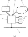
- FIG. 2 An example of the system according to the present invention is shown in Figure 2 .
- the system includes an electronic control unit (ECU) 8 of the type shown in Figure 1 .
- a particular ego vehicle may include a plurality of such ECUs 8.
- the ECU 8 is connected to an ego vehicle communication network 9 within the ego vehicle.
- the ego vehicle communication network 9 may be a CAN bus or a FlexRay system, for example.
- a particular ECU 8 may be connected to more than one such network, which may not be of the same type.
- the ECU may communicate with other ECUs in the ego vehicle via the ego vehicle communication network 9.
- the ECU 8 is connected to at least one sensor 10.
- three sensors 10 are connected to the ECU 8, although this number of sensors should not be considered limiting.
- the connections of each of the sensors 10 to the ECU 8 may be wired or wireless.
- the sensor connections may also be via the ego vehicle communication network 9.
- the connection between each sensor 10 and the ECU 8 may be a two-way connection - that is, the ECU 8 may receive data from the sensor 10 and the ECU 8 may send data and or commands to the sensors 10.
- the sensors 10 may be providing information concerning the state of the ego vehicle itself and/or the state of the surrounding environment.
- the sensors 10 may also provide some data reduction capability - that is determined parameters may be calculated at the sensors 10 and sent to the ECU 8 from the sensors 10, rather than (or in addition to) the sensors 10 sending raw measurements performed by the sensors 10 to the ECU 8.
- the ECU 8 is also capable of wireless communication with the internet across a 2-way internet communication link 11.
- the internet includes a cloud computing capability 12, to which the ECU 8 may offload processing tasks.
- the internet communication link 11 may comprise a connection to a mobile telephone communications network, for example.
- the ECU 8 may send processing tasks to the cloud 11 over the internet communication link 11, where the processing task is performed in the cloud 11, before the results of the processing task are sent back to the ECU 8 over the internet communication link 11.
- the internet communication link 11 may also provide access to data that is not available immediately to the ECU 8.
- data may include map data, for example.
- the ECU 8 also has a second communication link 13, which provides access to a distributed functionality 14 external to the ego vehicle.
- the distributed functionality may include Vehicle-to-Vehicle communications, and/or Vehicle-to-Infrastructure communications. These may permit driver assistance functionality and/or autonomous driving functionalities in which information can be shared with the ego vehicle, or to which the ego vehicle can share information across the second communication link 13.
- FIG 3 shows an example schematic architecture of the ECU 8.
- the ECU 8 includes a master microcontroller unit (MCU) 15 and a slave MCU 16.
- MCU master microcontroller unit
- the operations of the slave MCU 16 are controlled by the master MCU 16.
- Control commands and data can be exchanged between the master MCU 15 and the slave MCU 16 across the two-way MCU interconnection 17.
- the ECU schematic in Figure 3 includes two MCUs - the master MCU 15 and the slave MCU 16 - although an ECU 8 in accordance with the present invention could equally include more than two MCUs, or one MCU.
- Each of the master MCU 15 and the slave MCU 16 include a processor 18.
- Each processor 18 is a so-called multicore processor, which includes a plurality of processing cores 19.
- a multicore processor may include, for example, 2, 4, 8, 16, or more, processing cores. Hundreds or thousands of processing cores are also considered. As such, the present invention should not be limited to the number of cores, which will surely increase as processor technology develops.
- Each processing core 19 of the multicore processor may include a core memory 20.
- the processing cores 19 allow for parallel processing within the processor 18.
- Each of the processors 18 may also include a processor memory (not shown).
- the processor memory may be shared by the processing cores 19 in the respective processor 18.
- the ECU 8 includes an ECU memory 21, which is shared by the MCUs in the ECU (the master MCU 15 and the slave MCU 16, in the example of Figure 3 ).
- the ECU 8 may also be connected to a non-volatile data storage device (not shown), for example a flash device, a ROM unit, or a hard-drive.
- the data storage may also be located remotely, and be accessed via the internet, for example.
- FIG 4 shows a bird's eye view schematic of a first ego vehicle driving scenario.
- the ego vehicle 11 includes the driver assistance system 1 of the vehicle 2 shown in Figure 1 .
- the system may comprise an ECU 8 as shown in Figures 2 and 3 .
- the ego vehicle 22 is travelling along the road 23.
- the road 23 has two lanes 24, 25.
- the traffic in the two lanes 24, 25 travels in opposite directions along the road 23.
- the ego vehicle 22 is shown driving on the right, and so is located in the right-most lane 25, as shown.
- the ego vehicle 22 is equipped with a GPS receiver, which corresponds to an example of a sensor 10.
- a coarse geolocation measurement 26 of the ego vehicle 22 is made - in Figure 4 the course geolocation measurement 26 is indicated by the marker.
- the extent of the uncertainty 27 surrounding the coarse geolocation measurement 26 also referred to as the "uncertainty margin"
- the extent of the uncertainty is indicated by a circle; however, the uncertainty in a geolocation measurement may be non-circular. By way of example, the uncertainty may correspond to an area approximately 10 metres across.
- the uncertainty is simply a parameterisation of the probability distribution of the course geolocation measurement 26.
- the uncertainty 27 may correspond, for example, to a confidence level, e.g. the 1-, 2-, or 3-sigma confidence level, where sigma is the standard deviation of the coarse geolocation measurement 26.
- a confidence level e.g. the 1-, 2-, or 3-sigma confidence level, where sigma is the standard deviation of the coarse geolocation measurement 26.
- the uncertainty may be represented by a covariance matrix, and therefore correspond to a variance of the measurement.
- the uncertainty 27 extends into the left-most lane 24 of the road 23, and to the right of the right-most lane 25 in which the ego vehicle 22 is travelling.
- the uncertainty 27 also extends in front of, and behind, the ego vehicle 22.
- using the GPS receiver there is an uncertainty 27 about where on the road 23 the ego vehicle 22 is located.
- the direction of travel of the ego vehicle 22 is indicated by the arrow 28.
- the direction of travel 28 may correspond to a heading of the ego vehicle 22.
- the heading of the ego vehicle 22 may be calculated using the GPS receiver.
- the driver assistance system can perform manoeuvres (for example) at the correct position along the road 23. It is also important to know more accurately the location of the ego vehicle 22 in a transverse sense, so that the driver assistance system can determine in which lane 24, 25 of the road 23 the ego vehicle 22 is travelling. A more accurate location for the ego vehicle 22 is also useful for other driver assistance/autonomous driving system functionalities.
- a fine geolocation position is calculated according to the following methodology, which is implemented by the driver assistance system.
- the fine geolocation position has a smaller uncertainty than the coarse geolocation measurement 26, and is thus more reliable than the coarse geolocation measurement 26.
- the fine geolocation position may have a smaller longitudinal uncertainty and/or a smaller transverse uncertainty.
- Figure 5 shows a bird's eye view schematic of a second ego vehicle driving scenario. Elements in Figure 5 that are also shown in Figure 4 are labelled with the same reference numerals to avoid duplication. Description of those elements will also not be duplicated herein.
- a road sign 30 which is a first example of a static feature.
- the sign 30 is shown as flat (against the page) in Figure 5 , however this is for convenience of representation only. It will be appreciated that the sign 30 is intended to represent a sign that effectively protrudes upwardly from the ground upon which the road is located, in the conventional manner of road signage.
- the sign 30 is located at a position adjacent to the road 23.
- the sign 30 may be located directly at the edge of the road 23, or may be transversely set back from the edge of the road 23. In the latter case, there may be a "hard-shoulder" or emergency lane located between the sign 30 and the outermost lane intended for ordinary traffic use.
- Road signs as examples of static features, could alternatively be located on an overhead gantry, for example, or any other convenient location in which road signs are typically located - what is important is that the static feature is visible to sensors mounted to the ego vehicle 22, as will be described in more detail below.
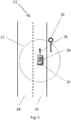
- Figure 6 shows a bird's eye view schematic of a second ego vehicle driving scenario. Elements shown in Figure 6 that are also shown in Figure 5 are labelled with the same reference numerals to avoid duplication. Description of those elements will also not be duplicated herein.
- the lanes 24, 25 are delineated by a separating road marking 31.
- the separating road marking 31 has a dashed line portion 32 and a solid line portion 33.
- a line marking transition point 34 is a location at which there is a transition between the dashed line portion 32 and the solid line portion 33.
- the ego vehicle 22 encounters the solid line portion 33 before encountering the dashed line portion 32 as the ego vehicle 22 travels along the right-most lane 25.
- the situation could be the opposite, i.e. that the ego vehicle 22 could encounter a dashed line portion 32 that transitions to a solid line portion 33. Indeed, if the ego vehicle 22 were travelling in the opposite direction along the road 23, in left-most lane 24, then that is precisely what would happen.
- the line marking transition point 34 is a second example of a static feature that is visible to sensors mounted to the ego vehicle 11.
- a post adjacent to the road, a bridge, a tunnel entrance, a building or other landmark would all be suitable as a static feature.
- visibly identifiable road marking features formed on the road are also suitable static features.
- the convergence point of linear road markings, the divergence point of linear road markings, or the transition point from a first road-marking regime to a second, different, road-marking regime are also suitable static features.
- a start and/or end point of a single road marking may also be used as a static feature.
- a dashed lane marking portion may constitute a plurality of sequential linear dashes in the conventional manner.
- Each linear dash (forming a single road marking) may have a dash start point and a dash end point.
- start and end in this context are used in the sense of the order in which the two ends of the dash are encountered by the travelling ego vehicle.
- Each of the dash start point and the dash end point (of a particular dash) may be used as a static feature in accordance with the present invention.
- each of the dash start point and dash end point of a plurality of dashes may be used as static features as the dashes are encountered by ego vehicle as it travels along the road.
- the ego vehicle 22 includes a camera system.
- the camera system may include a mono-camera (i.e. one point of view) or a stereo camera (i.e. two points of view). Camera systems with more than two points of view may also be used.
- the camera system is another example of a sensor 10.
- the embodiment is configured to calculate the position of the static feature relative to the ego vehicle 22.
- Such measurements may include apparent position, angular size, and/or shape of the static feature 30, 34 as detected in the image.
- the system may include knowledge of a standard, real world, size and/or shape of the static feature 30, 34.
- a sequence of images from the camera system may be used to determine the relative position of the static feature 30, 34. This may allow for a more accurate determination of the position of the static feature 30, 34 relative to the ego vehicle 22 because the apparent position, size and/or shape of the static feature 30, 34 will change in the view of the camera system as the ego vehicle 22 moves.
- the static feature 30, 34 is identified in a map.
- the map includes the real-world location of that static feature 30, 34.
- Such a real-world location may include a latitude and longitude of the static feature 30, 34.
- the map may be a so-called high-definition map that includes more information than a simple map. This process of identifying the static feature 30, 34 in a map is described below.
- the map may be stored in the non-volatile data storage device discussed above.
- the map data may be accessed via the internet.
- the map data may be partially stored in the non-volatile storage device or the ECU memory 21 in the manner of cached content, for example.
- the coarse GPS measurement 26, and optionally the uncertainty 27 of the coarse GPS measurement is used to define a sub-region of the map in which to search for the static feature 30, 34.
- the sub-region of the map may be the uncertainty/variance 27 of the coarse GPS measurement 26, or may be defined using the uncertainty/variance 27. In Figures 5 and 6 , the sub-region of the map may thus correspond to the area circumscribed by the uncertainty 27.
- the system is configured to search for a uniquely identified record of the static feature 30, 34. If, for example, within the sub-region, two records of two distinct potential matches for the static feature 30, 34 are found, then it may be impossible to identify in the map which of those two records corresponds to the static feature 30, 34 identified by, or from, the camera system. If it is not possible to identify uniquely the detected static feature 30, 34 in the sub-region of the map, then the system may wait for a predetermined time period before attempting the processing steps again. With the predetermined time period having elapsed, the scene visible to camera system will have changed as the ego vehicle 22 has moved along the road, and a different static feature 30, 34 may be in the field of view of the camera system. The above methodology can then be repeated for that further static feature 30, 34.
- a primary static feature may be used to initialise the location of the ego vehicle, which enables the detection and measurement of secondary static features.
- detection and measurement of secondary static features support the position derived for the ego vehicle as the ego vehicle travels between primary static features.
- Occurrence of the primary static features may be relatively rare when compared to the occurrence of the secondary static features as the ego vehicle travels along a road.
- the primary static features may be relatively rare static features, for example road signs or lane marking transition points.
- the secondary static features may be relatively common static features, for example dash start points and/or end points.
- Two or more static features 30, 34 may be identified and measured by the camera system. For example, if two static features 30, 34 are detected and measured simultaneously by the camera system, then the chance of being unable to find a unique pair of records within the sub-region of the map that corresponds to those two static features 30, 34 is reduced compared to that for a single static feature. Of course, a greater number still of static features 30, 34 will reduce further still the chances of being unable to identify uniquely the combination of the static features 30, 34 located within the sub-region. An improved accuracy is also achieved with larger angular separations between static features, as observed by the camera system. The system may be configured to identify static features with maximal angular separation.
- a first static feature may be a line marking transition 34 and a second static feature may be a road sign 30.
- each static feature 30, 34 is gathered from the map.
- the real-world location of each static feature 30, 34 is thus known to the system.
- Figure 7 shows an enlarged view of the scenario shown in Figure 6 .
- Elements shown in Figure 7 which are also shown in Figure 6 , are labelled with the same reference numerals to avoid duplication. Description of those elements will also not be duplicated herein. Only a portion of the uncertainty 27 is shown in Figure 7 .
- the real-world location of the line marking transition 34 is gathered from the map having been identified uniquely in the sub-region of the map.
- the relative position of the ego vehicle 22 and the line marking transition 34 is calculated using the measurement(s) of the visual appearance of the line marking transition 34, as described above.
- the embodiment uses a predetermined fixed point on the ego vehicle 22 as the origin of its frame of reference.
- the origin is taken to be the centre of the ego vehicle 22, as shown in Figure 7 .
- the choice of origin is a mathematical convenience, and is, in effect, inconsequential.
- the relative position between the ego vehicle 22 and the line marking transition 34 is broken down into a transverse component 35 and a longitudinal component 36.
- a position of the ego vehicle 22 is therefore calculated by using the real-world location of the line marking transition 34 and the relative position of the ego vehicle 22 and the line marking transition 34 (as calculated from the appearance of the line marking transition 34 to the camera system on the ego vehicle 22). This is referred to as the "static feature measurement" of the location of the ego vehicle 22.
- a static feature measurement of the location of the ego vehicle 22 can be derived for each of the static features 30, 34. Such measurements may be combined to form a single combined static feature measurement of the location of the ego vehicle 22.
- the position of the ego vehicle 22 is known via two independent methods.
- the first is the coarse geolocation measurement using the GPS receiver; the second is the position calculated using the ego vehicle position relative to the static feature 30, 34 (the real world position of which is known from the map).
- the latter of these positions is more accurate than the former.
- those measurements may be combined (or "fused") to form a fine geolocation position.
- the fine geolocation position may be more accurate than either of the measurements from which it is formed.
- the fusing of the positions may be performed by incorporating the position calculated using the ego vehicle position relative to the static feature as a measurement of the state of the ego vehicle (corresponding to the coarse position measurement of the ego vehicle) into the state of the of the ego vehicle.
- Such fusing may be achieved by using a Kalman filter to update the state of the ego vehicle to incorporate the position calculated using the ego vehicle position relative to the static feature.
- the Kalman filter may be an unscented Kalman filter. See the discussion of in connection with Figure 8 for more detail.
- the fine geolocation position may then be used for a variety of downstream driving aids, or in an autonomous driving system/functionality.
- the fine geolocation position determination may be performed repeatedly as the ego vehicle 22 travels along a road. An accurate geolocation of the ego vehicle may therefore be maintained for use in the system by constantly updating that position with static feature measurements of the location of the ego vehicle 22 as they are calculated as the ego vehicle 22 drives down a road.
- IMU inertial measurement unit
- a later time location measurement as determined using an IMU may also be fused with the coarse geolocation measurement in the same manner as the static feature measurement of the location of the ego vehicle. Again, such use of an IMU may improve the geolocation measurement performance of the driver assistance system.
- the system is also more resilient insofar as an accurate geolocation of the ego vehicle 22 may be maintained even in the absence of static features to measure and use, as above.
- the IMU may measure, for example, the yaw-rate and/or the speed of the ego vehicle 22, which can be used to calculate the position to which the ego vehicle 22 has moved since the last geolocation measurement.
- Figure 8 illustrates a schematic method in accordance with an embodiment of the present invention.
- any and all detected static features that are identified and measured by the camera system are transformed into to map co-ordinates. For each detected static feature, this transformation is performed using a current state of the ego vehicle state x ⁇ k , and the position of the detected static feature relative to the ego vehicle.
- the ego vehicle state x ⁇ k includes at least:
- the sub-region of the map may correspond to the variance of the ego vehicle state.
- the matching of the feature type means the checking of the type of the feature detected by the camera and the potential match for that feature in the map. For example, if the camera detects a road sign, then it is checked that there is only one static feature of a Type equal to "road sign" in the sub-region of the map.
- the state of the ego vehicle is then updated using the unscented Kalman filter to incorporate the static feature measurement of the positon of the ego vehicle derived from the measurement of the static feature and the map.
- a prediction for a future state of the ego vehicle is also made based on a predictive model using the unscented Kalman filter.
- the state is refined to include position measurements derived from a static feature each time that a static feature is uniquely identified.
- the covariance of the state may also be refined at the same time.
- the present inventors have noted that the unscented Kalman filter is particularly useful as the state estimator in this case. This is because of highly non-linear state observation and transition models required to predict a future state of the system from a current or previous state.
- the unscented Kalman filter is capable of describing highly non-linear systems without introducing large errors.
- the "no" path is taken.
- a prediction for the state of the ego vehicle is then made based on a predictive model using the unscented Kalman filter. In this case, however, no static feature measurement of the positon of the ego vehicle derived from the measurement of the static feature is available, and thus it is not incorporated into the state of the ego vehicle.
- a static feature measurement of the positon of the ego vehicle may improve the accuracy of the state and may reduce the size of the variance of the state.
- the sub-region of the map in which to identify the static features may correspond to the variance of the state.
- the sub-region of the map is made smaller by making and including in the state the static feature measurement of the positon of the ego vehicle. This reduction in the size of the sub-region means increases the likelihood that more commonly occurring static features may be uniquely identified in the sub-region of the map.
- the coarse measurement of the state of the ego vehicle may be initialised by a detection and measurement of a primary static feature, for example, a relatively rare static feature (such as a road sign or line marking transition).
- a primary static feature for example, a relatively rare static feature (such as a road sign or line marking transition).
- this improves the accuracy of the state of the ego vehicle and reduces the size of the variance of the state, thus reducing the size of the sub-region of the map in which to search for static features.
- this may allow a secondary static feature to be detected and measured to refine further the state of the ego vehicle, for example a relatively common static feature.
- a relatively common static feature may be dash start points and/or dash end points.
- secondary static features e.g. relatively common static features
- primary static features e.g. relatively rare static features
- the relative rarity and commonality of the relatively rare and relatively common static features described above refers to the chances of encountering said static features by the ego vehicle as the ego vehicle travels along a particular road.
- the rarity/commonality of the static features is relative to one another.
- the relatively common static features have a higher rate of relative occurrence than the relatively rare static features. In other words, along a particular stretch of road, an ego vehicle would expect to pass relatively common static features more often than the ego vehicle would expect to pass the relatively rare static features.
- relatively common static features may include the start and/or end of single road markings; relatively rare common features may include road signs and/or line marking transition points.
- the dash start points and/or dash end points of a linear dash may be located with a few metres of each other, whereas road signs may be located within hundreds of metres of each other, for example.
- the start and/or end of single road markings would correspond to relatively common static features; the road signs would correspond to relative rare static features.
Priority Applications (5)
| Application Number | Priority Date | Filing Date | Title |
|---|---|---|---|
| EP17181013.8A EP3428577A1 (fr) | 2017-07-12 | 2017-07-12 | Système d'assistance au conducteur et procédé |
| PCT/EP2018/068155 WO2019025112A1 (fr) | 2017-07-12 | 2018-07-04 | Système et procédé de guidage routier |
| US16/627,904 US11550330B2 (en) | 2017-07-12 | 2018-07-04 | Driver assistance system and method |
| CN201880045525.3A CN110869702A (zh) | 2017-07-12 | 2018-07-04 | 驾驶员辅助系统和方法 |
| US17/976,477 US20230047404A1 (en) | 2017-07-12 | 2022-10-28 | Driver assistance system and method |
Applications Claiming Priority (1)
| Application Number | Priority Date | Filing Date | Title |
|---|---|---|---|
| EP17181013.8A EP3428577A1 (fr) | 2017-07-12 | 2017-07-12 | Système d'assistance au conducteur et procédé |
Publications (1)
| Publication Number | Publication Date |
|---|---|
| EP3428577A1 true EP3428577A1 (fr) | 2019-01-16 |
Family
ID=59485127
Family Applications (1)
| Application Number | Title | Priority Date | Filing Date |
|---|---|---|---|
| EP17181013.8A Pending EP3428577A1 (fr) | 2017-07-12 | 2017-07-12 | Système d'assistance au conducteur et procédé |
Country Status (4)
| Country | Link |
|---|---|
| US (2) | US11550330B2 (fr) |
| EP (1) | EP3428577A1 (fr) |
| CN (1) | CN110869702A (fr) |
| WO (1) | WO2019025112A1 (fr) |
Cited By (1)
| Publication number | Priority date | Publication date | Assignee | Title |
|---|---|---|---|---|
| CN112092827A (zh) * | 2020-09-23 | 2020-12-18 | 北京百度网讯科技有限公司 | 自动驾驶功能控制方法、装置、电子设备及存储介质 |
Families Citing this family (5)
| Publication number | Priority date | Publication date | Assignee | Title |
|---|---|---|---|---|
| CN110375739B (zh) * | 2019-06-26 | 2021-08-24 | 中国科学院深圳先进技术研究院 | 一种移动端视觉融合定位方法、系统及电子设备 |
| DE102019213612A1 (de) * | 2019-09-06 | 2021-03-11 | Robert Bosch Gmbh | Verfahren und Vorrichtung zum Betreiben eines automatisierten Fahrzeugs |
| JP7421923B2 (ja) * | 2019-12-23 | 2024-01-25 | フォルシアクラリオン・エレクトロニクス株式会社 | 位置推定装置、及び位置推定方法 |
| AU2021236690A1 (en) * | 2020-03-20 | 2022-11-17 | Rosendin Electric, Inc. | An autonomous ground vehicle for solar module installation |
| CN114076601B (zh) * | 2021-11-16 | 2024-03-19 | 北京经纬恒润科技股份有限公司 | 辅助定位方法及装置 |
Citations (3)
| Publication number | Priority date | Publication date | Assignee | Title |
|---|---|---|---|---|
| EP2034271A1 (fr) * | 2006-06-21 | 2009-03-11 | Toyota Jidosha Kabushiki Kaisha | Dispositif de positionnement |
| US20150316386A1 (en) * | 2014-04-30 | 2015-11-05 | Toyota Motor Engineering & Manufacturing North America, Inc. | Detailed map format for autonomous driving |
| US20170016740A1 (en) * | 2015-07-16 | 2017-01-19 | Ford Global Technologies, Llc | Method and apparatus for determining a vehicle ego-position |
Family Cites Families (20)
| Publication number | Priority date | Publication date | Assignee | Title |
|---|---|---|---|---|
| JP2006208223A (ja) * | 2005-01-28 | 2006-08-10 | Aisin Aw Co Ltd | 車両位置認識装置及び車両位置認識方法 |
| JP4724043B2 (ja) * | 2006-05-17 | 2011-07-13 | トヨタ自動車株式会社 | 対象物認識装置 |
| CN101476891A (zh) * | 2008-01-02 | 2009-07-08 | 丘玓 | 移动物体的精确导航系统及方法 |
| US9194949B2 (en) * | 2011-10-20 | 2015-11-24 | Robert Bosch Gmbh | Methods and systems for precise vehicle localization using radar maps |
| EP2746137B1 (fr) * | 2012-12-19 | 2019-02-20 | Volvo Car Corporation | Procédé et système pour aider un conducteur |
| US9650337B2 (en) | 2013-02-14 | 2017-05-16 | Galderma Research & Development | Method of synthesising 4-piperidin-4-yl-benzene-1,3-diol and the salts of same and novel compound tert-butyl 4-(2,4-dihydroxy-phenyl)-4-hydroxy-piperidine-1-carboxylate |
| CN103207634A (zh) * | 2013-03-20 | 2013-07-17 | 北京工业大学 | 一种智能车辆中差分gps与惯性导航数据融合的系统和方法 |
| US9435653B2 (en) * | 2013-09-17 | 2016-09-06 | GM Global Technology Operations LLC | Sensor-aided vehicle positioning system |
| US9796400B2 (en) * | 2013-11-27 | 2017-10-24 | Solfice Research, Inc. | Real time machine vision and point-cloud analysis for remote sensing and vehicle control |
| US20150316387A1 (en) | 2014-04-30 | 2015-11-05 | Toyota Motor Engineering & Manufacturing North America, Inc. | Detailed map format for autonomous driving |
| CN105044757A (zh) * | 2015-06-29 | 2015-11-11 | 中国矿业大学 | 卫星信号遮蔽区域gnss差分与惯性测量组合测图方法 |
| US20170032676A1 (en) | 2015-07-30 | 2017-02-02 | Illinois Institute Of Technology | System for detecting pedestrians by fusing color and depth information |
| US10366204B2 (en) | 2015-08-03 | 2019-07-30 | Change Healthcare Holdings, Llc | System and method for decentralized autonomous healthcare economy platform |
| US10082797B2 (en) * | 2015-09-16 | 2018-09-25 | Ford Global Technologies, Llc | Vehicle radar perception and localization |
| CN105489035B (zh) * | 2015-12-29 | 2018-03-30 | 大连楼兰科技股份有限公司 | 应用在主动驾驶技术中检测交通信号灯的方法 |
| CN105676253B (zh) * | 2016-01-15 | 2019-01-01 | 武汉光庭科技有限公司 | 一种自动驾驶中基于城市道路标线地图的纵向定位系统及其方法 |
| GB2559908A (en) | 2016-05-13 | 2018-08-22 | Nchain Holdings Ltd | A method and system for verifying ownership of a digital asset using a distributed hash table and a peer-to-peer distributed ledger |
| US10209081B2 (en) * | 2016-08-09 | 2019-02-19 | Nauto, Inc. | System and method for precision localization and mapping |
| US10447480B2 (en) | 2016-12-30 | 2019-10-15 | Guardtime Sa | Event verification receipt system and methods |
| CN108303103B (zh) * | 2017-02-07 | 2020-02-07 | 腾讯科技(深圳)有限公司 | 目标车道的确定方法和装置 |
-
2017
- 2017-07-12 EP EP17181013.8A patent/EP3428577A1/fr active Pending
-
2018
- 2018-07-04 US US16/627,904 patent/US11550330B2/en active Active
- 2018-07-04 CN CN201880045525.3A patent/CN110869702A/zh active Pending
- 2018-07-04 WO PCT/EP2018/068155 patent/WO2019025112A1/fr active Application Filing
-
2022
- 2022-10-28 US US17/976,477 patent/US20230047404A1/en active Pending
Patent Citations (3)
| Publication number | Priority date | Publication date | Assignee | Title |
|---|---|---|---|---|
| EP2034271A1 (fr) * | 2006-06-21 | 2009-03-11 | Toyota Jidosha Kabushiki Kaisha | Dispositif de positionnement |
| US20150316386A1 (en) * | 2014-04-30 | 2015-11-05 | Toyota Motor Engineering & Manufacturing North America, Inc. | Detailed map format for autonomous driving |
| US20170016740A1 (en) * | 2015-07-16 | 2017-01-19 | Ford Global Technologies, Llc | Method and apparatus for determining a vehicle ego-position |
Cited By (1)
| Publication number | Priority date | Publication date | Assignee | Title |
|---|---|---|---|---|
| CN112092827A (zh) * | 2020-09-23 | 2020-12-18 | 北京百度网讯科技有限公司 | 自动驾驶功能控制方法、装置、电子设备及存储介质 |
Also Published As
| Publication number | Publication date |
|---|---|
| WO2019025112A1 (fr) | 2019-02-07 |
| US11550330B2 (en) | 2023-01-10 |
| US20230047404A1 (en) | 2023-02-16 |
| US20210149409A1 (en) | 2021-05-20 |
| CN110869702A (zh) | 2020-03-06 |
Similar Documents
| Publication | Publication Date | Title |
|---|---|---|
| US20230047404A1 (en) | Driver assistance system and method | |
| US11513518B2 (en) | Avoidance of obscured roadway obstacles | |
| JP7377317B2 (ja) | 道路の曲率データ無しでの進行レーン識別 | |
| US10668925B2 (en) | Driver intention-based lane assistant system for autonomous driving vehicles | |
| US11092456B2 (en) | Object location indicator system and method | |
| CN106873580B (zh) | 基于感知数据在交叉口处自主驾驶 | |
| EP3299921A1 (fr) | Assistance spécifique à la position d'un véhicule pour le système de commande de véhicule autonome | |
| EP3324556A1 (fr) | Système de communication visuelle pour véhicules de conduite autonomes (adv) | |
| DE102017100013A1 (de) | Bestimmen der fahrerabsicht an strassenverkehrskreuzungen zum vermeiden der kollision von automobilen | |
| GB2528360A (en) | Traffic light anticipation | |
| CN113741485A (zh) | 车路协同自动驾驶的控制方法、装置、电子设备及车辆 | |
| US11195027B2 (en) | Automated crowd sourcing of road environment information | |
| CN115328110A (zh) | 用于自主运载工具的系统和方法以及存储介质 | |
| KR20220124616A (ko) | 근접 규칙을 사용한 자율 주행 차량의 제어 | |
| DE112020002546T5 (de) | Steuervorrichtung für autonomes fahren, steuersystem für autonomes fahren und steuerverfahren für autonomes fahren | |
| CN109425861B (zh) | 本车位置可信度运算装置 | |
| CN114212108A (zh) | 自动驾驶方法、装置、车辆、存储介质及产品 | |
| CN113734191A (zh) | 人工地虚造传感器数据以发起用于自动驾驶车辆的安全动作 | |
| CN113196356A (zh) | 交通灯估计 | |
| US20220340139A1 (en) | Vehicle Route Modification to Improve Vehicle Location Information | |
| CN116343506A (zh) | 用于运载工具的方法、运载工具和存储介质 | |
| US11926342B2 (en) | Autonomous vehicle post-action explanation system | |
| US11645906B2 (en) | Navigation system with traffic state detection mechanism and method of operation thereof | |
| US20240124060A1 (en) | A method for determining whether an automatic collision avoidance steering maneuver should be executed or not | |
| US11731492B2 (en) | Systems and methods for guiding a vehicle occupant's attention |
Legal Events
| Date | Code | Title | Description |
|---|---|---|---|
| PUAI | Public reference made under article 153(3) epc to a published international application that has entered the european phase |
Free format text: ORIGINAL CODE: 0009012 |
|
| STAA | Information on the status of an ep patent application or granted ep patent |
Free format text: STATUS: THE APPLICATION HAS BEEN PUBLISHED |
|
| AK | Designated contracting states |
Kind code of ref document: A1 Designated state(s): AL AT BE BG CH CY CZ DE DK EE ES FI FR GB GR HR HU IE IS IT LI LT LU LV MC MK MT NL NO PL PT RO RS SE SI SK SM TR |
|
| AX | Request for extension of the european patent |
Extension state: BA ME |
|
| STAA | Information on the status of an ep patent application or granted ep patent |
Free format text: STATUS: REQUEST FOR EXAMINATION WAS MADE |
|
| 17P | Request for examination filed |
Effective date: 20190618 |
|
| RBV | Designated contracting states (corrected) |
Designated state(s): AL AT BE BG CH CY CZ DE DK EE ES FI FR GB GR HR HU IE IS IT LI LT LU LV MC MK MT NL NO PL PT RO RS SE SI SK SM TR |
|
| STAA | Information on the status of an ep patent application or granted ep patent |
Free format text: STATUS: EXAMINATION IS IN PROGRESS |
|
| 17Q | First examination report despatched |
Effective date: 20200401 |
|
| STAA | Information on the status of an ep patent application or granted ep patent |
Free format text: STATUS: EXAMINATION IS IN PROGRESS |
|
| STAA | Information on the status of an ep patent application or granted ep patent |
Free format text: STATUS: EXAMINATION IS IN PROGRESS |
|
| RAP1 | Party data changed (applicant data changed or rights of an application transferred) |
Owner name: ARRIVER SOFTWARE AB |