EP3428502B1 - Safety joint - Google Patents
Safety joint Download PDFInfo
- Publication number
- EP3428502B1 EP3428502B1 EP18181171.2A EP18181171A EP3428502B1 EP 3428502 B1 EP3428502 B1 EP 3428502B1 EP 18181171 A EP18181171 A EP 18181171A EP 3428502 B1 EP3428502 B1 EP 3428502B1
- Authority
- EP
- European Patent Office
- Prior art keywords
- plug
- socket
- depressurizing
- passage
- hydrogen gas
- Prior art date
- Legal status (The legal status is an assumption and is not a legal conclusion. Google has not performed a legal analysis and makes no representation as to the accuracy of the status listed.)
- Active
Links
Images



Classifications
-
- B—PERFORMING OPERATIONS; TRANSPORTING
- B60—VEHICLES IN GENERAL
- B60K—ARRANGEMENT OR MOUNTING OF PROPULSION UNITS OR OF TRANSMISSIONS IN VEHICLES; ARRANGEMENT OR MOUNTING OF PLURAL DIVERSE PRIME-MOVERS IN VEHICLES; AUXILIARY DRIVES FOR VEHICLES; INSTRUMENTATION OR DASHBOARDS FOR VEHICLES; ARRANGEMENTS IN CONNECTION WITH COOLING, AIR INTAKE, GAS EXHAUST OR FUEL SUPPLY OF PROPULSION UNITS IN VEHICLES
- B60K15/00—Arrangement in connection with fuel supply of combustion engines or other fuel consuming energy converters, e.g. fuel cells; Mounting or construction of fuel tanks
-
- F—MECHANICAL ENGINEERING; LIGHTING; HEATING; WEAPONS; BLASTING
- F16—ENGINEERING ELEMENTS AND UNITS; GENERAL MEASURES FOR PRODUCING AND MAINTAINING EFFECTIVE FUNCTIONING OF MACHINES OR INSTALLATIONS; THERMAL INSULATION IN GENERAL
- F16L—PIPES; JOINTS OR FITTINGS FOR PIPES; SUPPORTS FOR PIPES, CABLES OR PROTECTIVE TUBING; MEANS FOR THERMAL INSULATION IN GENERAL
- F16L37/00—Couplings of the quick-acting type
- F16L37/28—Couplings of the quick-acting type with fluid cut-off means
- F16L37/38—Couplings of the quick-acting type with fluid cut-off means with fluid cut-off means in only one of two pipe-end fittings
- F16L37/40—Couplings of the quick-acting type with fluid cut-off means with fluid cut-off means in only one of two pipe-end fittings with a lift valve being opened automatically when the coupling is applied
-
- F—MECHANICAL ENGINEERING; LIGHTING; HEATING; WEAPONS; BLASTING
- F16—ENGINEERING ELEMENTS AND UNITS; GENERAL MEASURES FOR PRODUCING AND MAINTAINING EFFECTIVE FUNCTIONING OF MACHINES OR INSTALLATIONS; THERMAL INSULATION IN GENERAL
- F16K—VALVES; TAPS; COCKS; ACTUATING-FLOATS; DEVICES FOR VENTING OR AERATING
- F16K17/00—Safety valves; Equalising valves, e.g. pressure relief valves
- F16K17/20—Excess-flow valves
-
- B—PERFORMING OPERATIONS; TRANSPORTING
- B60—VEHICLES IN GENERAL
- B60K—ARRANGEMENT OR MOUNTING OF PROPULSION UNITS OR OF TRANSMISSIONS IN VEHICLES; ARRANGEMENT OR MOUNTING OF PLURAL DIVERSE PRIME-MOVERS IN VEHICLES; AUXILIARY DRIVES FOR VEHICLES; INSTRUMENTATION OR DASHBOARDS FOR VEHICLES; ARRANGEMENTS IN CONNECTION WITH COOLING, AIR INTAKE, GAS EXHAUST OR FUEL SUPPLY OF PROPULSION UNITS IN VEHICLES
- B60K15/00—Arrangement in connection with fuel supply of combustion engines or other fuel consuming energy converters, e.g. fuel cells; Mounting or construction of fuel tanks
- B60K15/03—Fuel tanks
- B60K15/04—Tank inlets
-
- B—PERFORMING OPERATIONS; TRANSPORTING
- B67—OPENING, CLOSING OR CLEANING BOTTLES, JARS OR SIMILAR CONTAINERS; LIQUID HANDLING
- B67D—DISPENSING, DELIVERING OR TRANSFERRING LIQUIDS, NOT OTHERWISE PROVIDED FOR
- B67D7/00—Apparatus or devices for transferring liquids from bulk storage containers or reservoirs into vehicles or into portable containers, e.g. for retail sale purposes
- B67D7/06—Details or accessories
- B67D7/32—Arrangements of safety or warning devices; Means for preventing unauthorised delivery of liquid
-
- F—MECHANICAL ENGINEERING; LIGHTING; HEATING; WEAPONS; BLASTING
- F16—ENGINEERING ELEMENTS AND UNITS; GENERAL MEASURES FOR PRODUCING AND MAINTAINING EFFECTIVE FUNCTIONING OF MACHINES OR INSTALLATIONS; THERMAL INSULATION IN GENERAL
- F16L—PIPES; JOINTS OR FITTINGS FOR PIPES; SUPPORTS FOR PIPES, CABLES OR PROTECTIVE TUBING; MEANS FOR THERMAL INSULATION IN GENERAL
- F16L29/00—Joints with fluid cut-off means
- F16L29/02—Joints with fluid cut-off means with a cut-off device in one of the two pipe ends, the cut-off device being automatically opened when the coupling is applied
-
- F—MECHANICAL ENGINEERING; LIGHTING; HEATING; WEAPONS; BLASTING
- F16—ENGINEERING ELEMENTS AND UNITS; GENERAL MEASURES FOR PRODUCING AND MAINTAINING EFFECTIVE FUNCTIONING OF MACHINES OR INSTALLATIONS; THERMAL INSULATION IN GENERAL
- F16L—PIPES; JOINTS OR FITTINGS FOR PIPES; SUPPORTS FOR PIPES, CABLES OR PROTECTIVE TUBING; MEANS FOR THERMAL INSULATION IN GENERAL
- F16L33/00—Arrangements for connecting hoses to rigid members; Rigid hose-connectors, i.e. single members engaging both hoses
-
- F—MECHANICAL ENGINEERING; LIGHTING; HEATING; WEAPONS; BLASTING
- F16—ENGINEERING ELEMENTS AND UNITS; GENERAL MEASURES FOR PRODUCING AND MAINTAINING EFFECTIVE FUNCTIONING OF MACHINES OR INSTALLATIONS; THERMAL INSULATION IN GENERAL
- F16L—PIPES; JOINTS OR FITTINGS FOR PIPES; SUPPORTS FOR PIPES, CABLES OR PROTECTIVE TUBING; MEANS FOR THERMAL INSULATION IN GENERAL
- F16L37/00—Couplings of the quick-acting type
- F16L37/22—Couplings of the quick-acting type in which the connection is maintained by means of balls, rollers or helical springs under radial pressure between the parts
- F16L37/23—Couplings of the quick-acting type in which the connection is maintained by means of balls, rollers or helical springs under radial pressure between the parts by means of balls
-
- F—MECHANICAL ENGINEERING; LIGHTING; HEATING; WEAPONS; BLASTING
- F16—ENGINEERING ELEMENTS AND UNITS; GENERAL MEASURES FOR PRODUCING AND MAINTAINING EFFECTIVE FUNCTIONING OF MACHINES OR INSTALLATIONS; THERMAL INSULATION IN GENERAL
- F16L—PIPES; JOINTS OR FITTINGS FOR PIPES; SUPPORTS FOR PIPES, CABLES OR PROTECTIVE TUBING; MEANS FOR THERMAL INSULATION IN GENERAL
- F16L37/00—Couplings of the quick-acting type
- F16L37/28—Couplings of the quick-acting type with fluid cut-off means
- F16L37/30—Couplings of the quick-acting type with fluid cut-off means with fluid cut-off means in each of two pipe-end fittings
-
- F—MECHANICAL ENGINEERING; LIGHTING; HEATING; WEAPONS; BLASTING
- F16—ENGINEERING ELEMENTS AND UNITS; GENERAL MEASURES FOR PRODUCING AND MAINTAINING EFFECTIVE FUNCTIONING OF MACHINES OR INSTALLATIONS; THERMAL INSULATION IN GENERAL
- F16L—PIPES; JOINTS OR FITTINGS FOR PIPES; SUPPORTS FOR PIPES, CABLES OR PROTECTIVE TUBING; MEANS FOR THERMAL INSULATION IN GENERAL
- F16L37/00—Couplings of the quick-acting type
- F16L37/28—Couplings of the quick-acting type with fluid cut-off means
- F16L37/30—Couplings of the quick-acting type with fluid cut-off means with fluid cut-off means in each of two pipe-end fittings
- F16L37/36—Couplings of the quick-acting type with fluid cut-off means with fluid cut-off means in each of two pipe-end fittings with two lift valves being actuated to initiate the flow through the coupling after the two coupling parts are locked against withdrawal
-
- F—MECHANICAL ENGINEERING; LIGHTING; HEATING; WEAPONS; BLASTING
- F16—ENGINEERING ELEMENTS AND UNITS; GENERAL MEASURES FOR PRODUCING AND MAINTAINING EFFECTIVE FUNCTIONING OF MACHINES OR INSTALLATIONS; THERMAL INSULATION IN GENERAL
- F16L—PIPES; JOINTS OR FITTINGS FOR PIPES; SUPPORTS FOR PIPES, CABLES OR PROTECTIVE TUBING; MEANS FOR THERMAL INSULATION IN GENERAL
- F16L55/00—Devices or appurtenances for use in, or in connection with, pipes or pipe systems
- F16L55/10—Means for stopping flow in pipes or hoses
-
- F—MECHANICAL ENGINEERING; LIGHTING; HEATING; WEAPONS; BLASTING
- F16—ENGINEERING ELEMENTS AND UNITS; GENERAL MEASURES FOR PRODUCING AND MAINTAINING EFFECTIVE FUNCTIONING OF MACHINES OR INSTALLATIONS; THERMAL INSULATION IN GENERAL
- F16L—PIPES; JOINTS OR FITTINGS FOR PIPES; SUPPORTS FOR PIPES, CABLES OR PROTECTIVE TUBING; MEANS FOR THERMAL INSULATION IN GENERAL
- F16L55/00—Devices or appurtenances for use in, or in connection with, pipes or pipe systems
- F16L55/10—Means for stopping flow in pipes or hoses
- F16L55/1007—Couplings closed automatically when broken
-
- F—MECHANICAL ENGINEERING; LIGHTING; HEATING; WEAPONS; BLASTING
- F16—ENGINEERING ELEMENTS AND UNITS; GENERAL MEASURES FOR PRODUCING AND MAINTAINING EFFECTIVE FUNCTIONING OF MACHINES OR INSTALLATIONS; THERMAL INSULATION IN GENERAL
- F16L—PIPES; JOINTS OR FITTINGS FOR PIPES; SUPPORTS FOR PIPES, CABLES OR PROTECTIVE TUBING; MEANS FOR THERMAL INSULATION IN GENERAL
- F16L55/00—Devices or appurtenances for use in, or in connection with, pipes or pipe systems
- F16L55/10—Means for stopping flow in pipes or hoses
- F16L55/1015—Couplings closed automatically when disengaging force exceeds preselected value
-
- F—MECHANICAL ENGINEERING; LIGHTING; HEATING; WEAPONS; BLASTING
- F16—ENGINEERING ELEMENTS AND UNITS; GENERAL MEASURES FOR PRODUCING AND MAINTAINING EFFECTIVE FUNCTIONING OF MACHINES OR INSTALLATIONS; THERMAL INSULATION IN GENERAL
- F16L—PIPES; JOINTS OR FITTINGS FOR PIPES; SUPPORTS FOR PIPES, CABLES OR PROTECTIVE TUBING; MEANS FOR THERMAL INSULATION IN GENERAL
- F16L57/00—Protection of pipes or objects of similar shape against external or internal damage or wear
-
- F—MECHANICAL ENGINEERING; LIGHTING; HEATING; WEAPONS; BLASTING
- F16—ENGINEERING ELEMENTS AND UNITS; GENERAL MEASURES FOR PRODUCING AND MAINTAINING EFFECTIVE FUNCTIONING OF MACHINES OR INSTALLATIONS; THERMAL INSULATION IN GENERAL
- F16L—PIPES; JOINTS OR FITTINGS FOR PIPES; SUPPORTS FOR PIPES, CABLES OR PROTECTIVE TUBING; MEANS FOR THERMAL INSULATION IN GENERAL
- F16L57/00—Protection of pipes or objects of similar shape against external or internal damage or wear
- F16L57/005—Protection of pipes or objects of similar shape against external or internal damage or wear specially adapted for the ends of pipes
-
- F—MECHANICAL ENGINEERING; LIGHTING; HEATING; WEAPONS; BLASTING
- F17—STORING OR DISTRIBUTING GASES OR LIQUIDS
- F17C—VESSELS FOR CONTAINING OR STORING COMPRESSED, LIQUEFIED OR SOLIDIFIED GASES; FIXED-CAPACITY GAS-HOLDERS; FILLING VESSELS WITH, OR DISCHARGING FROM VESSELS, COMPRESSED, LIQUEFIED, OR SOLIDIFIED GASES
- F17C13/00—Details of vessels or of the filling or discharging of vessels
- F17C13/04—Arrangement or mounting of valves
-
- F—MECHANICAL ENGINEERING; LIGHTING; HEATING; WEAPONS; BLASTING
- F17—STORING OR DISTRIBUTING GASES OR LIQUIDS
- F17C—VESSELS FOR CONTAINING OR STORING COMPRESSED, LIQUEFIED OR SOLIDIFIED GASES; FIXED-CAPACITY GAS-HOLDERS; FILLING VESSELS WITH, OR DISCHARGING FROM VESSELS, COMPRESSED, LIQUEFIED, OR SOLIDIFIED GASES
- F17C13/00—Details of vessels or of the filling or discharging of vessels
- F17C13/12—Arrangements or mounting of devices for preventing or minimising the effect of explosion ; Other safety measures
-
- F—MECHANICAL ENGINEERING; LIGHTING; HEATING; WEAPONS; BLASTING
- F17—STORING OR DISTRIBUTING GASES OR LIQUIDS
- F17C—VESSELS FOR CONTAINING OR STORING COMPRESSED, LIQUEFIED OR SOLIDIFIED GASES; FIXED-CAPACITY GAS-HOLDERS; FILLING VESSELS WITH, OR DISCHARGING FROM VESSELS, COMPRESSED, LIQUEFIED, OR SOLIDIFIED GASES
- F17C5/00—Methods or apparatus for filling containers with liquefied, solidified, or compressed gases under pressures
- F17C5/06—Methods or apparatus for filling containers with liquefied, solidified, or compressed gases under pressures for filling with compressed gases
-
- F—MECHANICAL ENGINEERING; LIGHTING; HEATING; WEAPONS; BLASTING
- F17—STORING OR DISTRIBUTING GASES OR LIQUIDS
- F17C—VESSELS FOR CONTAINING OR STORING COMPRESSED, LIQUEFIED OR SOLIDIFIED GASES; FIXED-CAPACITY GAS-HOLDERS; FILLING VESSELS WITH, OR DISCHARGING FROM VESSELS, COMPRESSED, LIQUEFIED, OR SOLIDIFIED GASES
- F17C7/00—Methods or apparatus for discharging liquefied, solidified, or compressed gases from pressure vessels, not covered by another subclass
-
- F—MECHANICAL ENGINEERING; LIGHTING; HEATING; WEAPONS; BLASTING
- F17—STORING OR DISTRIBUTING GASES OR LIQUIDS
- F17C—VESSELS FOR CONTAINING OR STORING COMPRESSED, LIQUEFIED OR SOLIDIFIED GASES; FIXED-CAPACITY GAS-HOLDERS; FILLING VESSELS WITH, OR DISCHARGING FROM VESSELS, COMPRESSED, LIQUEFIED, OR SOLIDIFIED GASES
- F17C2205/00—Vessel construction, in particular mounting arrangements, attachments or identifications means
- F17C2205/03—Fluid connections, filters, valves, closure means or other attachments
- F17C2205/0302—Fittings, valves, filters, or components in connection with the gas storage device
- F17C2205/0352—Pipes
-
- F—MECHANICAL ENGINEERING; LIGHTING; HEATING; WEAPONS; BLASTING
- F17—STORING OR DISTRIBUTING GASES OR LIQUIDS
- F17C—VESSELS FOR CONTAINING OR STORING COMPRESSED, LIQUEFIED OR SOLIDIFIED GASES; FIXED-CAPACITY GAS-HOLDERS; FILLING VESSELS WITH, OR DISCHARGING FROM VESSELS, COMPRESSED, LIQUEFIED, OR SOLIDIFIED GASES
- F17C2205/00—Vessel construction, in particular mounting arrangements, attachments or identifications means
- F17C2205/03—Fluid connections, filters, valves, closure means or other attachments
- F17C2205/0302—Fittings, valves, filters, or components in connection with the gas storage device
- F17C2205/037—Quick connecting means, e.g. couplings
-
- F—MECHANICAL ENGINEERING; LIGHTING; HEATING; WEAPONS; BLASTING
- F17—STORING OR DISTRIBUTING GASES OR LIQUIDS
- F17C—VESSELS FOR CONTAINING OR STORING COMPRESSED, LIQUEFIED OR SOLIDIFIED GASES; FIXED-CAPACITY GAS-HOLDERS; FILLING VESSELS WITH, OR DISCHARGING FROM VESSELS, COMPRESSED, LIQUEFIED, OR SOLIDIFIED GASES
- F17C2205/00—Vessel construction, in particular mounting arrangements, attachments or identifications means
- F17C2205/03—Fluid connections, filters, valves, closure means or other attachments
- F17C2205/0302—Fittings, valves, filters, or components in connection with the gas storage device
- F17C2205/0376—Dispensing pistols
-
- F—MECHANICAL ENGINEERING; LIGHTING; HEATING; WEAPONS; BLASTING
- F17—STORING OR DISTRIBUTING GASES OR LIQUIDS
- F17C—VESSELS FOR CONTAINING OR STORING COMPRESSED, LIQUEFIED OR SOLIDIFIED GASES; FIXED-CAPACITY GAS-HOLDERS; FILLING VESSELS WITH, OR DISCHARGING FROM VESSELS, COMPRESSED, LIQUEFIED, OR SOLIDIFIED GASES
- F17C2221/00—Handled fluid, in particular type of fluid
- F17C2221/01—Pure fluids
- F17C2221/012—Hydrogen
-
- F—MECHANICAL ENGINEERING; LIGHTING; HEATING; WEAPONS; BLASTING
- F17—STORING OR DISTRIBUTING GASES OR LIQUIDS
- F17C—VESSELS FOR CONTAINING OR STORING COMPRESSED, LIQUEFIED OR SOLIDIFIED GASES; FIXED-CAPACITY GAS-HOLDERS; FILLING VESSELS WITH, OR DISCHARGING FROM VESSELS, COMPRESSED, LIQUEFIED, OR SOLIDIFIED GASES
- F17C2223/00—Handled fluid before transfer, i.e. state of fluid when stored in the vessel or before transfer from the vessel
- F17C2223/01—Handled fluid before transfer, i.e. state of fluid when stored in the vessel or before transfer from the vessel characterised by the phase
- F17C2223/0107—Single phase
- F17C2223/0123—Single phase gaseous, e.g. CNG, GNC
-
- F—MECHANICAL ENGINEERING; LIGHTING; HEATING; WEAPONS; BLASTING
- F17—STORING OR DISTRIBUTING GASES OR LIQUIDS
- F17C—VESSELS FOR CONTAINING OR STORING COMPRESSED, LIQUEFIED OR SOLIDIFIED GASES; FIXED-CAPACITY GAS-HOLDERS; FILLING VESSELS WITH, OR DISCHARGING FROM VESSELS, COMPRESSED, LIQUEFIED, OR SOLIDIFIED GASES
- F17C2223/00—Handled fluid before transfer, i.e. state of fluid when stored in the vessel or before transfer from the vessel
- F17C2223/03—Handled fluid before transfer, i.e. state of fluid when stored in the vessel or before transfer from the vessel characterised by the pressure level
- F17C2223/036—Very high pressure (>80 bar)
-
- F—MECHANICAL ENGINEERING; LIGHTING; HEATING; WEAPONS; BLASTING
- F17—STORING OR DISTRIBUTING GASES OR LIQUIDS
- F17C—VESSELS FOR CONTAINING OR STORING COMPRESSED, LIQUEFIED OR SOLIDIFIED GASES; FIXED-CAPACITY GAS-HOLDERS; FILLING VESSELS WITH, OR DISCHARGING FROM VESSELS, COMPRESSED, LIQUEFIED, OR SOLIDIFIED GASES
- F17C2260/00—Purposes of gas storage and gas handling
- F17C2260/04—Reducing risks and environmental impact
- F17C2260/042—Reducing risk of explosion
-
- F—MECHANICAL ENGINEERING; LIGHTING; HEATING; WEAPONS; BLASTING
- F17—STORING OR DISTRIBUTING GASES OR LIQUIDS
- F17C—VESSELS FOR CONTAINING OR STORING COMPRESSED, LIQUEFIED OR SOLIDIFIED GASES; FIXED-CAPACITY GAS-HOLDERS; FILLING VESSELS WITH, OR DISCHARGING FROM VESSELS, COMPRESSED, LIQUEFIED, OR SOLIDIFIED GASES
- F17C2265/00—Effects achieved by gas storage or gas handling
- F17C2265/06—Fluid distribution
- F17C2265/065—Fluid distribution for refuelling vehicle fuel tanks
-
- F—MECHANICAL ENGINEERING; LIGHTING; HEATING; WEAPONS; BLASTING
- F17—STORING OR DISTRIBUTING GASES OR LIQUIDS
- F17C—VESSELS FOR CONTAINING OR STORING COMPRESSED, LIQUEFIED OR SOLIDIFIED GASES; FIXED-CAPACITY GAS-HOLDERS; FILLING VESSELS WITH, OR DISCHARGING FROM VESSELS, COMPRESSED, LIQUEFIED, OR SOLIDIFIED GASES
- F17C2270/00—Applications
- F17C2270/01—Applications for fluid transport or storage
- F17C2270/0134—Applications for fluid transport or storage placed above the ground
- F17C2270/0139—Fuel stations
-
- F—MECHANICAL ENGINEERING; LIGHTING; HEATING; WEAPONS; BLASTING
- F17—STORING OR DISTRIBUTING GASES OR LIQUIDS
- F17C—VESSELS FOR CONTAINING OR STORING COMPRESSED, LIQUEFIED OR SOLIDIFIED GASES; FIXED-CAPACITY GAS-HOLDERS; FILLING VESSELS WITH, OR DISCHARGING FROM VESSELS, COMPRESSED, LIQUEFIED, OR SOLIDIFIED GASES
- F17C2270/00—Applications
- F17C2270/01—Applications for fluid transport or storage
- F17C2270/0165—Applications for fluid transport or storage on the road
- F17C2270/0168—Applications for fluid transport or storage on the road by vehicles
-
- Y—GENERAL TAGGING OF NEW TECHNOLOGICAL DEVELOPMENTS; GENERAL TAGGING OF CROSS-SECTIONAL TECHNOLOGIES SPANNING OVER SEVERAL SECTIONS OF THE IPC; TECHNICAL SUBJECTS COVERED BY FORMER USPC CROSS-REFERENCE ART COLLECTIONS [XRACs] AND DIGESTS
- Y02—TECHNOLOGIES OR APPLICATIONS FOR MITIGATION OR ADAPTATION AGAINST CLIMATE CHANGE
- Y02E—REDUCTION OF GREENHOUSE GAS [GHG] EMISSIONS, RELATED TO ENERGY GENERATION, TRANSMISSION OR DISTRIBUTION
- Y02E60/00—Enabling technologies; Technologies with a potential or indirect contribution to GHG emissions mitigation
- Y02E60/30—Hydrogen technology
- Y02E60/32—Hydrogen storage
Definitions
- the present invention relates to a safety joint for a filling apparatus for filling gas such as hydrogen gas used as fuel, more particularly to a safety joint for separating the filling apparatus and a filling hose from each other in an emergency.
- a hydrogen filling station is filled hydrogen gas after a filling nozzle 202 mounted on an end of a filling hose 201 and a vehicle side filling port 203 are connected with each other.
- the filling is controlled depending on the maximum using pressure of a hydrogen tank 204 mounted in the vehicle A.
- a hydrogen filling apparatus is pulled down and broken to inject a hydrogen gas, or, devices such as the filling nozzle 202 and the filling hose 201 are broken to inject a hydrogen gas, so that it becomes a dangerous condition.
- a safety joint 300 for emergency releasing is mounted on an area between the hydrogen filling apparatus 200 and the filling hose 201, the safety joint 300 is separated when a tensile force more or equal to a predetermined value is applied to the filling hose 201, and it is prevented that the hydrogen filling apparatus 200 and devices such as the filling nozzle 202 and the filling hose 201 are broken.
- the safety joint for emergency releasing is proposed a safety joint in which a passage in a member on a weighing machine (the hydrogen filling apparatus 200) side (the passage communicating with a weighing machine side hose) and a passage in a member on a vehicle side (the passage communicating with the hose having the filling nozzle) are orthogonal with each other (refer to Japanese Patent Publication No. 2007-120717 gazette for example).
- the safety joint for emergency releasing has a long rod as a member on the weighing machine side or on the vehicle side, and the rod is exposed when the weighing machine side member and the vehicle side member are separated from each other. Then, when the member having the long rod falls or collides with the weighing machine or the vehicle, there is a possibility that the exposed rod is broken.
- a technique for solving the problem has not been proposed yet.
- the present invention has been made in consideration of the above problems in the prior art, and the object thereof is to provide a safety joint capable of preventing a component of the weighing machine (hydrogen filling apparatus) side member or the vehicle side member is broken in case that the weighing machine side member and the vehicle side member are separated from each other in an emergency when the vehicle runs while hydrogen gas is filled for instance.
- a safety joint having the features of claim1 is provided.
- the longitudinal size of the cover (50) is longer than that of the valve rod (2), and the cover (50) is configured to thoroughly surround the valve rod (2).
- the safety joint (100) according to the present invention is arranged near a weighing machine (hydrogen filling apparatus) and near a base portion of the filling hose communicating with the filling nozzle.
- cover (50) does not prevent the separation between a weighing machine (hydrogen filling apparatus) side member and a vehicle side member, but the cover (50) is not separated from the weighing machine side member or the vehicle side member after they are separated from each other.
- one of the plug (10) and the socket (20) includes depressurizers (30, 30A) including a main body portion (31) made of metal, a depressurizing communication hole (31B) communicating with a hydrogen gas passage (31A) in the main body portion (31), a depressurizing plug (32) made of metal, the depressurizing plug (32) insertable into the depressurizing communication hole (31B), and tapered portions (pin tapered portion 32B of the depressurizing plug 32, tapered portion 31BB of the depressurizing communication hole 31B) formed on the depressurizing communication hole (31B) and the depressurizing plug (32) respectively, the tapered portions (32B, 31BB) having complemental shapes with each other.
- depressurizers (30, 30A) including a main body portion (31) made of metal, a depressurizing communication hole (31B) communicating with a hydrogen gas passage (31A) in the main body portion (31), a depressurizing plug (32) made of metal, the depressurizing plug (3
- the safety joint (100) further includes a relief circuit (31C) for outflowing a filled fluid (hydrogen gas for instance) and communicating with the depressurizing communication hole (31B), an outlet of the relief circuit (31C) being formed at a position separated from an area above the depressurizing plug (32).
- a relief circuit (31C) for outflowing a filled fluid (hydrogen gas for instance) and communicating with the depressurizing communication hole (31B), an outlet of the relief circuit (31C) being formed at a position separated from an area above the depressurizing plug (32).
- a length (L) of a hydrogen passage side end portion (32A: pin end portion) of the depressurizing plug (32) and a length (HL) of a hydrogen passage side end portion (31BA: small diameter portion) of the depressurizing communication hole (31B) are long.
- the length (L) of the hydrogen passage side end portion (32A: pin end portion) is short, in the depressurizer (30A) can be mounted a locking pin insertion hole (31D) (the depressurizer 30A can be configured such that a locking pin P for suppressing rotation of a hexagonal rod spanner S can be inserted therein).
- one of the plug (10) and the socket (20) has the cover (50) for surrounding (protecting) the valve rod (2: plug side rod), so that impacts are not directly added to the valve rod (2) even if a member on which the valve rod (2) is mounted (one of the plug 10 and the socket 20) is separated from the member on which the valve rod (2) is not mounted (another one of the plug 10 and the socket 20) to fall or collide with the weighing machine or the vehicle in an emergency such that a vehicle suddenly moves when hydrogen is filled. Therefore, it is prevented that the valve rod (2) is broken.
- the safety joint (100) according to the prevent invention when the safety joint (100) according to the prevent invention is attached to the filling hose on the filling nozzle side, weight of the hose becomes heavy by the safety joint (100), so that there is a possibility that workers feel inconvenience to handle the hose.
- the safety joint (100) when the safety joint (100) is disposed near the weighing machine and near the base portion of the filling hose communicating with the filling nozzle, the safety joint (100) is supported by the weighing machine, so that the weight of the hose does not become heavy and there is no possibility that workers feel inconvenience to handle the hose.
- central axes of a passage (the in-plug passage 1A) in the plug (10) and another passage (the in-socket passage 21A) in the socket (20) do not form a straight line (orthogonal with each other for instance), so that central axes of a valve rod (rod 2) in the plug (10) and a valve rod (rod 22) in the socket (20) do not form a straight line also, the plug side rod 2 and the socket side rod 22 are not pressed with each other in a straight line under a condition that end portions (pin connecting end portions) contact with each other.
- the safety joint 100 can be made small in size and light in weight, and when high pressure hydrogen gas is filled for instance, operability of the filling hose improves.
- a metal main portion (31) in a metal main portion (31) may be formed a depressurizing communication hole (31B) communicating with a hydrogen gas passage (31A), a metal depressurizing plug (32) insertable into the depressurizing communication hole (31B) can be mounted, and to the depressurizing communication hole (31B) and the depressurizing plug (32) may be formed tapered portions (a pin tapered portion 32B of the depressurizing plug 32 and a tapered portion 31BB of the depressurizing communication hole 31B) having complemental shapes with each other.
- the gap (cross sectional area ( ⁇ /4)(d 2 - ⁇ 2 ), annular gap) formed between an outer periphery of the hydrogen passage side end portion (32A: pin end portion, diameter size " ⁇ ") of the depressurizing plug 32 and an inner periphery of the hydrogen passage side end portion (31BA: small diameter portion, inner diameter "d") of the depressurizing communication hole 31B works as an orifice, and imparts pressure loss to high pressure hydrogen gas flowing through the orifice, so that injecting velocity of hydrogen gas outflowing from the depressurizers (30, 30A) becomes slow, which prevents the filling hose with the depressurizers (30, 30A) from unexpectedly moving around.
- the relief circuit (31C) for outflowing hydrogen gas may be formed, and the outlet of the relief circuit (31C) can be disposed apart from an area above the depressurizing plug (32), even if sparks generate by contacts between metals when the hexagonal rod spanner (S: hexagonal wrench) is inserted into a hexagonal hole (32E: plug hexagonal hole) at an upper portion of the plug (32) to be rotated, a position where the hydrogen gas outflows from relief circuit (31C) is separated from a position where the sparks generate, so that the a possibility that the hydrogen gas catches fire due to the sparks becomes extremely low, and safety of the filling apparatus improves.
- S hexagonal wrench
- a whole safety joint according to the embodiment is shown as the numeral 100, and the safety joint 100 includes a plug 10 (covered with a cover described below) with a cylindrical shape and a socket 20.
- the socket 20 is connected to the plug 10 (the plug 10 is inserted into the socket 20), opening a shutoff valve to communicate an in-socket passage 21A (refer to Fig. 2 etc.) with an in-plug passage 1A ( Fig. 2 ).
- the plug 10 and the socket 20 are connected with each other.
- the plug 10 is basically connected to a vehicle (not shown in in Fig.
- the socket 20 is basically connected to a hydrogen filling apparatus (or a dispenser, a weighing machine, not shown in Fig. 1 ) side.
- a hydrogen filling apparatus or a dispenser, a weighing machine, not shown in Fig. 1
- FIG. 1 on an area extending on the vehicle side (left side in Fig. 1 ) in the central axis C1 of the in-plug passage 1A is arranged a filling hose not shown, and a hydrogen gas introducing port side (upper side in Fig. 1 ) in the central axis C2 of the in-socket passage 21A is connected to a hydrogen filling apparatus not shown.
- a cover 50 is mounted to protect a plug side rod 2 ( Figs. 2 to 5 ) mounted to the plug 10, the longitudinal size of the cover 50 is longer than that of the plug side rod 2, and thoroughly surrounds the plug side rod 2.
- the cover 50 surrounds an area from a portion near one end of the plug 10 to another portion near another end of the plug 10 in the central axis C1 direction of the in-plug passage 1A, and thoroughly surrounds the plug side rod 2 mounted in the plug 10.
- the cover 50 is attached to the plug 10, and surrounds a portion (lower portion in Fig. 1 ) of the socket 20.
- the cover 50 is connected to the plug 10 such that the cover 50 does not prevent the separation between the plug 10 and the socket 20 but the cover 50 is connected to the plug 10 to a degree that the cover 50 does not separate from the plug 10 after the plug 10 and the socket 20 are separated from each other in an emergency such that a vehicle moves when hydrogen is filled.
- the safety joint 100 is arranged near the hydrogen filling apparatus 200 ( Fig. 12 ) and near the base portion of the filling hose 201.
- a depressurizer 30 (or 30A).
- the depressurizer 30 is not surrounded by the cover 50, and a plug hexagonal hole 32E into which a depressurizing plug formed on an outer side surface of the depressurizer 30 is exposed in Fig. 1 .
- a hydrogen gas passage 31A ( Figs. 6 to 9 ), and the hydrogen gas passage 31A is connected to the in-plug passage 1A ( Figs. 2 to 5 ) of the plug 10.
- a filling hose not shown.
- the numeral 31F in Fig. 1 indicates a concave portion to which the filling hose on the vehicle side is connected, and the numeral 31C indicates (an outlet of an outer side surface of) a relief circuit in the depressurizer 30.
- the depressurizer 30 (or 30A) will be explained with reference to Figs. 6 to 10 .
- the plug 10 and the socket 20 of the safety joint 100 will be explained with reference to Figs. 2 to 5 .
- the cover 50 explained with reference to Fig. 1 is shown by doted lines in Figs. 3 and 5 to simplify illustrations, but is deleted in Figs. 2 and 4 to avoid complexities in illustrations.
- the plug 10 shaped like a cylinder as a whole body includes a plug main body 1 and a plug side rod case 3.
- a hydrogen gas supply port 1B To a central portion (a vertically central portion in Fig. 2 ) of the vehicle side (right side in Fig. 2 ) end portion of the plug main body 1 is mounted to a central portion (a vertically central portion in Fig. 2 ) of the vehicle side (right side in Fig. 2 ) end portion of the plug main body 1 is mounted to a central portion (a vertically central portion in Fig. 2 ) of the vehicle side (right side in Fig. 2 ) end portion of the plug main body 1 is mounted to a central portion (a vertically central
- the in-plug passage 1A On the plug main body 1 is formed the in-plug passage 1A extending in a lateral direction of Fig. 2 , and on the in-plug passage 1A is formed a plug side valve element accommodating portion 1C.
- the in-plug passage 1A communicates with a passage in the plug side rod case 3, and communicates through a passage in the plug side valve element accommodating portion 1C with the hydrogen gas supply port 1B.
- a plug side valve element 6 On the vehicle side (right side in Fig. 2 ) of the plug side valve element 6 accommodated in the valve element accommodating portion 1C is arranged a plug side spring 4, which energizes the plug side valve element 6 toward the socket 20 side (left side in Fig. 2 ). Then, the plug side valve element 6 and a valve seat 1F configure a plug side shutoff valve 5, and the plug side shutoff valve 5 has a function of shutting/opening the plug side passage 1A. An end portion on the opposite side (left side in Fig. 2 ) of the valve element 6 configures a locking portion 2A.
- a flange portion 1D On the outside in a radial direction of the hydrogen gas supply port 1B of the plug main body 1 is formed a flange portion 1D.
- the flange portion 1D is a connecting surface to the depressurizer 30 (or 30A: refer to Figs. 1 and 6 to 10) not shown. Then, when the plug 10 and the socket 20 are connected with each other, the surface (left side surface of the flange portion 1D in Fig. 2 ) of the flange portion 1D on the opposite side to the surface connected to the depressurizer 30 ( Fig. 1 ) abuts on a plug accommodating housing 26.
- a connecting channel 1E On an outer peripheral surface of the plug main body 1 is formed a connecting channel 1E, and to the connecting channel 1E is fitted connecting balls 40 for connecting the plug 10 and the socket 20 with each other.
- the plug side rod case 3 projects from the plug main body 1 toward the socket 20 side (left side in Fig. 2 ).
- a socket 20 side end portion On a socket 20 side end portion is shaped a opening portion 21C whose hollow cylindrical shape is closed, and in Figs. 2 and 3 in an inner space of the opening portion 21C is accommodated the plug side rod 2.
- an opening 3A In the outer periphery of the plug side rod case 3, at a predetermined position (corresponding to a lower portion of a socket side rod 22) is formed an opening 3A for passage connection.
- the plug side rod case 3 is inserted into an opening portion 21C of the socket 20 (the socket main body 21), and the in-plug passage 1A and an in-socket passage 21A are communicated with each other through the opening 3A.
- a locking ball channel 3B near the socket 20 side end portion of the plug side rod case 3 is formed a locking ball channel 3B, and in the locking ball channel 3B are held locking balls 7.
- a tapered portion of the locking portion 2A are pressed the locking balls 7 radially outward.
- the locking balls 7 do not move radially outward the plug side rod case 3.
- Fig. 5 under a condition that the plug 10 and the socket 20 are separated from each other, there is no member that prevents the locking balls 7 from moving radially outward, and the locking balls 7 position radially outward (the plug side rod case 3).
- the socket 20 shaped like a cylinder as a whole body has the socket main body 21 and the plug accommodating housing 26.
- a hydrogen filling apparatus side upper side in Fig. 2
- a hydrogen gas introducing port 21B On a horizontally central portion of the socket main body 21 shown in Fig. 2 is formed the in-socket passage 21A extending in the vertical direction, and in a socket side valve element accommodating portion 21D (enlarged portion) formed on the in-socket passage 21A is accommodated a socket side valve element 25.
- the in-socket passage 21A communicates from the hydrogen gas introducing port 21B through the socket side valve element accommodating portion 21D and a hollow portion of the socket side rod 22, with the opening portion 21C of the socket main body 21.
- an end portion on the side separated from the plug 10 of the opening portion 21C is opened.
- the plug side rod case 3 into the opening portion 21C is inserted the plug side rod case 3, and the in-socket passage 21A communicates through the hollow portion of the socket side rod 22 and the opening 3A of the plug side rod case 3 with the in-plug passage 1A.
- On the inner periphery of the opening portion 21C of the socket main body 21 are mounted O-rings SS1, SS2.
- the socket side valve element 25 To the socket side valve element 25 is connected the socket side rod 22. On the side of the hydrogen gas introducing port 21B (upper side in Fig. 2 ) of the socket side valve element 25 is arranged a socket side spring 23, and the socket side spring 23 energizes the socket side valve element 25 toward a valve seat 21E (lower side in Fig. 2 ). Then, the valve element 25 and the valve seat 21E configure a socket side shutoff valve 24, which has a function of shutting/opening the socket side passage 21A. A hydrogen gas fed to the valve element accommodating portion 21D inflows through the openings 22A formed on the socket side rod 22 to the hollow portion of the socket side rod 22. Here, the hollow portion of the socket side rod 22 configures a portion of the in-socket passage 21A.
- the plug accommodating housing 26 whose end portion is opened projects from the socket main body 21 toward the plug 10 (right side in Fig. 2 ).
- On the inner peripheral surface of the plug accommodating housing 26 are formed at-connection arrangement portions 26A and an at-disconnection accommodating channel 26B.
- On the at-connection arrangement portions 26A are arranged the connecting balls 40 when the plug 10 and the socket 20 are connected with each other, and in the at-disconnection accommodating channel 26B are accommodated the connecting balls 40 moved from the at-connection arrangement portions 26A when from the socket 20 is disconnected the plug 10.
- the horizontal (lateral in Fig. 2 ) position of the at-connection arrangement portions 26A corresponds to that of the plug side connecting channel 1E of the plug main body 1.
- the main body 1 of the plug 10 When hydrogen gas is filled, the main body 1 of the plug 10 is inserted into the plug accommodating housing 26, and by the connecting balls 40 and the connecting spring 41 are integrally connected the plug 10 and the socket 20 with each other.
- the spring holder 42 to which the connecting spring 41 is attached positions in a gap between the inner peripheral surface of the plug accommodating housing 26 and the outer peripheral surface of the plug main body 1.
- the connecting balls 40 are fitted into connecting ball holes 42A formed on the spring holder 42, and engage with the plug side connecting channel 1E of the plug main body 1.
- the socket 20 side of the connecting balls 40 left side in Fig.
- the spring holder 42 engages with the plug 10 through the connecting balls 40 and the plug side connecting channel 1E into which the connecting balls 40 are fitted. Therefore, when the plug 10 and the socket 20 are connected with each other, the plug 10 and the socket 20 are integrated with each other so as to hold the spring holder 42 and the connecting balls 40 in between.
- the connecting balls 40 disengaged from the plug side connecting channel 1E and move in the arrow M directions, and as show in Fig. 4 , the connecting balls 40 are fitted into the at-disconnection accommodating channel 26B ( Fig. 2 ) of the plug accommodating housing 26. Then, the plug 10 is disconnected from the socket 20, resulting in a disjoint condition shown in Figs. 4 and 5 .
- the predetermined value (boundary value that the joint between the plug 10 and the socket 20 is released) is determined based on specifications of the hydrogen filling apparatus, the filling hose and the like, and based on the predetermined value are designed the plug 10 and the plug accommodating housing 26, the connecting balls 40, the connecting spring 41 and the spring holder 42 of the socket 20.
- the in-socket passage 21A (the hydrogen gas introducing port 21B, the socket side valve element accommodating portion 21D, the hollow portion of the socket side rod 22 and the opening portion 21C of the socket 20) and the in-plug passage 1A (the hollow portion of the plug side rod case 3, the plug side valve element accommodating portion 1C) are communicated with each other, and from the side of the hydrogen filling apparatus (weighing machine) to the side of the vehicle flows hydrogen gas.
- a tensile force more or equal to a predetermined magnitude is applied to the filling hose so as to detach the connecting balls 40 from the plug side connecting channel 1E, the plug 10 and the socket 20 are disconnected from each other.
- the plug side rod case 3 of the plug 10 is detached from the opening portion 21C of the socket 20 (socket main body 21), and the socket side valve element 25 moves downward in Fig. 4 by an elastically repulsive force of the socket side spring 23.
- the socket side valve element 25 seats on the socket side valve seat 21E, and the socket side shutoff valve 24 shuts the in-socket passage 21A.
- the locking portion 2A ( Fig. 2 ) of the plug side rod 2 moves leftward from the locking balls 7 by the elastically repulsive force of the plug side spring 4.
- the plug side valve element 6 seats on the plug side valve seat 1F, and the plug side shutoff valve 5 shuts the in-plug passage 1A. Since the socket side shutoff valve 24 and the plug side shutoff valve 5 close the in-socket passage 21A and the in-plug passage 1A respectively, hydrogen gas does not leak from vehicle side and hydrogen filling apparatus side.
- the cover 50 is mounted to protect the plug side rod 2, the cover 50 covering the plug 10 and a portion of the socket 20.
- the cover 50 is expressed with dashed lines in Figs. 3 and 5 .
- FIG. 5 when the plug 10 and the socket 20 are disconnected from each other, the cover 50 attached to the plug 10 side separates from the socket 20.
- a length of the cover 50 is long in a longitudinal direction of the plug side rod 2, and the cover 50 is configured such that perfectly covering the plug side rod 2. Therefore, even if the plug 10 and the socket 20 are separated from each other, and the plug 10 falls or collides with the hydrogen filling apparatus or the like, the plug side rod 2 is protected by the cover 50.
- the end portion opposite to the plug 10 side (left side in Fig. 2 ) of the opening portion 21C in which the plug side rod case 3 is inserted opens to be a through hole.
- the end portion opposite to the plug 10 side (left side in Fig. 2 ) can be closed to be a blind hole.
- the O-ring SS2 is not required.
- the depressurizer 30 (or 30A) will be explained with reference to Figs. 6 to 10 .
- the depressurizer 30 is, as shown in Fig. 1 for example, attached to the plug 10 of the safety joint 100, and has a function of depressurizing high pressure hydrogen gas in an area on the vehicle side from the plug 10 (in-plug passage 1A, Figs. 2 to 5 ) when the plug 10 and the socket 20 are separated from each other.
- high pressure hydrogen gas in an area on the hydrogen filling apparatus side from the socket 20 is depressurized by a depressurizing mechanism not shown on the hydrogen filling apparatus side.
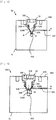
- the depressurizer 30 has a metal depressurizer main body portion (hereinafter referred to as "main body portion”) 31 with a nearly rectangular parallelepiped shape and a metal depressurizing plug 32, and the depressurizing plug 32 is configured to engage with (screw to) a depressurizing communication hole 31B of the main body portion 31.
- main body portion 31 On the left side of the main body portion 31 is formed a projecting portion 31E, and the projecting portion 31E is connected to the plug 10 side of the safety joint 100.
- a concaved portion 31F On the right side of the main body portion 31 is formed a concaved portion 31F, and to the concaved portion 31F is connected the vehicle side filling hose ( Fig. 12 ).
- the projecting portion 31E is connected to the vehicle side filling hose, and the concaved portion 31F is connected to the plug 10 side of the safety joint 100.
- the depressurizing communication hole 31B communicating from an upper surface 31G with the hydrogen gas passage 31A extends in a vertical direction, and with the depressurizing communication hole 31B communicates a relief circuit 31C (refer to Figs. 7 and 8 : not shown in Fig. 6 ).
- a cross sectional area of the relief circuit 31C is set small to be enough to add a sufficient pressure loss to a flowing hydrogen gas.
- the depressurizing communication hole 31B has a small diameter portion 31BA communicating with the hydrogen gas passage 31A, a tapered portion 31BB, the first middle diameter portion 31BC, the second middle diameter portion 31BD, and a female screw portion 31BE communicating with the upper surface 31G.
- the depressurizing plug 32 has a pin end portion 32A with a minimum diameter in a lower end portion, a pin tapered portion 32B, a pin middle diameter portion 32C, a male screw portion 32D forming a male screw on an outer periphery.
- the pin tapered portion 32B of the depressurizing plug 32 and the tapered portion 31BB of the depressurizing communication hole 31B are complementary shapes with each other, and the pin tapered portion 32B contacts the tapered portion 31BB.
- the depressurizing plug 32 and the main body portion 31 are made of metal, so that a portion where the pin tapered portion 32B and the tapered portion 31BB contact with each other configures a so-called "metal seal".
- an O-ring 31H prevents high pressure hydrogen gas from injecting upward from a gap between the depressurizing plug 32 and the depressurizing communication hole 31B when the depressurizing plug 32 sufficiently moves relative to (rises against: refer to Fig. 6 ) the depressurizing communication hole 31B (in a condition that engagement between the depressurizing plug 32 and the main body portion 31 is released: refer to Fig. 8 ).
- a male screw formed on the outer periphery of the male screw portion 32D of the depressurizing plug 32 is formed on an upper surface of the depressurizing plug 32.
- a plug hexagonal hole 32E is formed on an upper surface of the depressurizing plug 32, and a hexagonal rod spanner S is inserted into the plug hexagonal hole 32E to be rotated as shown in Fig. 10 when the depressurizing plug 32 is attached to/detached from the depressurizing communication hole 31B.
- the depressurizing communication hole 31B communicates with the relief circuit 31C.
- the pin tapered portion 32B and the tapered portion 31BB of the depressurizing communication hole 31B contact with each other to configure the metal seal, so that high pressure hydrogen gas flowing in the hydrogen gas passage 31A is completely shut by the metal seal and does not flow into the relief circuit 31C.
- the depressurizing plug 32 is rotated in a depressurizing direction by the hexagonal rod spanner S, the engagement between the female screw portion 31BE of the depressurizing communication hole 31B and the male screw portion 32D of the depressurizing plug 32 is released, the pin tapered portion 32B and the tapered portion 31BB of the depressurizing communication hole 31B are separated from each other, and the metal seal is released.
- a condition that the metal seal is released is shown in Fig. 8 .
- a diameter size ⁇ of the pin end portion 32A is set slightly smaller than the inner diameter d of the small diameter portion 31BA of the depressurizing communication hole 31B ( ⁇ d), and between an outer periphery of the pin end portion 32A and an inner periphery of the small diameter portion 31BA of the depressurizing communication hole 31B is formed an annular gap whose cross sectional area is ( ⁇ /4)(d 2 - ⁇ 2 ).
- high pressure hydrogen gas filled in the hydrogen gas passage 31A inflows through the annular gap into the relief circuit 31C and passes through the relief circuit 31C to outflow from the depressurizer 30 as shown by the arrow ⁇ .
- a hydrogen gas outlet of the relief circuit 31C is formed at a position apart from the plug hexagonal hole 32E.
- a length L of the pin end portion 32A (vertical length in Fig. 7 ) and a length HL of the small diameter portion 31BA of the depressurizing communication hole 31B are relatively long, and a length LW of the pin end portion 32A inserted into the small diameter portion 31BA of the depressurizing communication hole 31B is relatively long also.
- a depressurizer 30A different from the depressurizer 30 shown in Figs. 6 to 8 is shown a depressurizer 30A different from the depressurizer 30 shown in Figs. 6 to 8 .
- the length L (vertical length in Fig. 9 ) of the pin end portion 32A of the plug 32 is clearly shorter than that of the depressurizer 30 shown in Fig. 7
- the length LW (refer to the depressurizer 30 shown in Fig. 7 ) of the pin end portion 32A inserted into the small diameter portion 31BA is shorter than that also. Therefore, when in depressurizing shown in Fig.
- a locking pin insertion hole 31D on the upper surface 31G of the main body portion 31 is formed a locking pin insertion hole 31D, and into the locking pin insertion hole 31D is insertable a locking pin P for suppressing rotation of the hexagonal rod spanner S.
- the locking pin P By the locking pin P, excessive rotation of the hexagonal rod spanner S is suppressed, and a condition that the gap between the pin end portion 32A of the plug 32 and the small diameter portion 31BA of the depressurizing communication hole 31B exists is maintained, which functions to generate a pressure loss in hydrogen gas.
- the arrow D indicates the filling hose on the vehicle side
- the arrow E indicates the plug 10 side in the safety joint 100.
- the depressurizer 30 shown in Figs. 6 to 8 also, the locking pin P and the locking pin insertion hole 31D can be mounted to prevent the excessive rotation of the hexagonal rod spanner S.
- Figs. 9 and 10 to the same members as those shown in Figs. 6 to 8 are attached the same numerals as those, and overlapped explanation is omitted. Then, other construction and action effect of the depressurizer 30A shown in Figs. 9 and 10 are the same as those of the depressurizer 30.
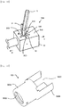
- the cover 50 is integrally constituted by metal members, and has a main body portion 50A with a cylindrical shape and a socket inserted portion 50B.
- the main body portion 50A of the cover 50 covers the plug main body 1 and the plug accommodating housing 26 (refer to Fig. 2 etc.) of the socket 20, and the socket inserted portion 50B covers the plug side rod accommodating case 3 and the plug side rod 2 ( Figs. 2 to 4 ).
- a space portion 50C of the socket inserted portion 50B is accommodated a connected portion of the plug 10 and the socket 20, the connected portion positioning lower side of the socket 20.
- the cover 50 is attached to the plug 10 by a conventionally known method.
- the cover 50 is mounted to protect the plug side rod 2 when the plug 10 and the socket 20 are separated from each other, so that the cover 50 surrounds the socket 20 side such that the separation between the socket 20 and the plug 10 are not prevented.
- An end portion opposite to the socket inserted portion 50B (left side in Fig. 11 ) in the main body portion 50A of the cover 50 has an opening 50D.
- the plug main body 1 is connected through the depressurizer 30 (or 30A) to the vehicle side (refer to Fig. 1 ).
- the cover 50 is mounted to completely surround the plug side rod 2 (valve rod) mounted on the plug 10 and/or the plug side rod accommodating case 3 including the longitudinal directions thereof, so that it is prevented that the plug side rod 2 is broken because impacts are not directly acted on the plug side rod 2 even if the plug 10 falls or collides with the hydrogen filling apparatus or the vehicle in case that the plug 10 and the socket 20 are separated from each other in an emergency when the vehicle runs while hydrogen is filled.
- the plug side rod 2 valve rod mounted on the plug 10 and/or the plug side rod accommodating case 3 including the longitudinal directions thereof
- the cover 50 is securely attached to the plug 10 side, and covers the socket 20 side such that separation of the socket is not prevented, so that it maintains that the cover 50 covers the plug side rod 2, and the cover 50 separates from the socket 20 side when the plug 10 and the socket 20 are separated from each other. Therefore, the plug side rod 2 can be surely protected.
- the safety joint 100 is arranged near the hydrogen filling apparatus (weighing machine) and near a base portion of the filling hose communicating with the filling nozzle, so that the safety joint 100 is supported by the hydrogen filling apparatus, and weight of the hose does not increase. Therefore, there is no possibility that it becomes difficult for filling workers to handle the hose.
- central axes of the in-plug passage 1A and the in-socket passage 1A do not form a straight line, and are orthogonal with each other, so that central axes of the plug side rod 2 and the socket side rod 22 do not form a straight line also, the plug side rod 2 and the socket side rod 22 are not pressed with each other under a condition that end portions (pin connecting end portions) contact with each other. Therefore, even if high pressure hydrogen gas is fed, forces that push end portions of the socket side rod 22 and the plug side rod 2 with each other do not increase, and the socket 20 and the plug 10 are not separated from each other.
- the safety joint 100 can be made small in size and light in weight, and operability when hydrogen gas is filled improves.
- the plug 10 and the socket 20 are connected with each other by the connecting balls (connecting members) 40 radially mounted at plurality of portions, so that a condition that the plug 10 and the socket 20 are connected with each other is surely maintained.
- the connecting balls 40 are configured to release the connection when an external force in a separating direction more or equal to a predetermined value acts on the connecting balls 40, so that the external force acting on the filling hose (tensile force acting on the filling hose when the vehicle runs while hydrogen is filled) separates the plug 10 and the socket 20 from each other regardless of pressures in the passages in the plug 10 and the socket 20.
- the depressurizers 30, 30A are mounted on the plug 10, when the plug 10 and the socket 20 are separated from each other for example, high pressure hydrogen gas in the filling hose can be discharged at small flow rate and low pressure outside the filling hose (outside the depressurizers 30, 30A). Therefore, it is prevented that the high pressure hydrogen gas rapidly injects, and the filling hose unexpectedly moves around due to the rapid injection of the hydrogen gas.
- a portion where the pin tapered portion 32B of the depressurizing plug 32 and the tapered portion 31BB of the depressurizing communication hole 31B contact with each other configures metal seal to completely shut high pressure hydrogen gas flowing in the hydrogen gas passage 31A.
- the gap (cross sectional area ( ⁇ /4)(d 2 - ⁇ 2 ), annular gap) formed between an outer periphery of the hydrogen passage side end portion (32A: pin end portion, diameter size " ⁇ ") of the depressurizing plug 32 and inner periphery of the hydrogen passage side end portion (31BA: small diameter portion, inner diameter "d") of the depressurizing communication hole 31B works as an orifice, and imparts pressure loss to high pressure hydrogen gas flowing through the orifice, so that injecting velocity of hydrogen gas outflowing from the depressurizers 30, 30A becomes slow.
- the relief circuit 31C for outflowing hydrogen gas is formed, and the hydrogen gas outlet of the relief circuit 31C is formed at a position apart from an area above the depressurizing plug 32. Then, even if sparks generate by contacts between metals when the hexagonal rod spanner S is inserted into the plug hexagonal hole 32E mounted on the upper portion of the plug 32 to be rotated, a possibility that the hydrogen gas catches fire due to the sparks becomes extremely low, and safety thereof improves.
Landscapes
- Engineering & Computer Science (AREA)
- General Engineering & Computer Science (AREA)
- Mechanical Engineering (AREA)
- Life Sciences & Earth Sciences (AREA)
- Sustainable Development (AREA)
- Sustainable Energy (AREA)
- Chemical & Material Sciences (AREA)
- Combustion & Propulsion (AREA)
- Transportation (AREA)
- Filling Or Discharging Of Gas Storage Vessels (AREA)
- Quick-Acting Or Multi-Walled Pipe Joints (AREA)
Description
- The present invention relates to a safety joint for a filling apparatus for filling gas such as hydrogen gas used as fuel, more particularly to a safety joint for separating the filling apparatus and a filling hose from each other in an emergency.
- For example, to a vehicle A using hydrogen as fuel, as show in
Fig. 12 , at a hydrogen filling station is filled hydrogen gas after a fillingnozzle 202 mounted on an end of afilling hose 201 and a vehicleside filling port 203 are connected with each other. The filling is controlled depending on the maximum using pressure of ahydrogen tank 204 mounted in the vehicle A. Here, when the vehicle A runs to pull thefilling hose 201 while hydrogen gas is filled, a hydrogen filling apparatus is pulled down and broken to inject a hydrogen gas, or, devices such as thefilling nozzle 202 and thefilling hose 201 are broken to inject a hydrogen gas, so that it becomes a dangerous condition. In order to prevent the condition, asafety joint 300 for emergency releasing is mounted on an area between thehydrogen filling apparatus 200 and thefilling hose 201, thesafety joint 300 is separated when a tensile force more or equal to a predetermined value is applied to thefilling hose 201, and it is prevented that thehydrogen filling apparatus 200 and devices such as thefilling nozzle 202 and thefilling hose 201 are broken. - As the safety joint for emergency releasing is proposed a safety joint in which a passage in a member on a weighing machine (the hydrogen filling apparatus 200) side (the passage communicating with a weighing machine side hose) and a passage in a member on a vehicle side (the passage communicating with the hose having the filling nozzle) are orthogonal with each other (refer to Japanese Patent Publication No.
2007-120717 - The contents of Japanese Patent Publication No.
2007-120717 - The present invention has been made in consideration of the above problems in the prior art, and the object thereof is to provide a safety joint capable of preventing a component of the weighing machine (hydrogen filling apparatus) side member or the vehicle side member is broken in case that the weighing machine side member and the vehicle side member are separated from each other in an emergency when the vehicle runs while hydrogen gas is filled for instance.
- According to an aspect of the present invention, a safety joint having the features of claim1 is provided.
- Here, it is preferable that the longitudinal size of the cover (50) is longer than that of the valve rod (2), and the cover (50) is configured to thoroughly surround the valve rod (2). In addition, it is preferable that the safety joint (100) according to the present invention is arranged near a weighing machine (hydrogen filling apparatus) and near a base portion of the filling hose communicating with the filling nozzle.
- Here, "capable of being attached" defines that, in an emergency such that a vehicle suddenly moves when hydrogen is filled, the cover (50) does not prevent the separation between a weighing machine (hydrogen filling apparatus) side member and a vehicle side member, but the cover (50) is not separated from the weighing machine side member or the vehicle side member after they are separated from each other.
- In addition, in the present invention, it is preferable that one of the plug (10) and the socket (20) includes depressurizers (30, 30A) including a main body portion (31) made of metal, a depressurizing communication hole (31B) communicating with a hydrogen gas passage (31A) in the main body portion (31), a depressurizing plug (32) made of metal, the depressurizing plug (32) insertable into the depressurizing communication hole (31B), and tapered portions (pin tapered
portion 32B of thedepressurizing plug 32, tapered portion 31BB of the depressurizingcommunication hole 31B) formed on the depressurizing communication hole (31B) and the depressurizing plug (32) respectively, the tapered portions (32B, 31BB) having complemental shapes with each other. In this case, it is preferable that the safety joint (100) further includes a relief circuit (31C) for outflowing a filled fluid (hydrogen gas for instance) and communicating with the depressurizing communication hole (31B), an outlet of the relief circuit (31C) being formed at a position separated from an area above the depressurizing plug (32). - In the depressurizer (30), it is preferable that a length (L) of a hydrogen passage side end portion (32A: pin end portion) of the depressurizing plug (32) and a length (HL) of a hydrogen passage side end portion (31BA: small diameter portion) of the depressurizing communication hole (31B) are long. However, when the length (L) of the hydrogen passage side end portion (32A: pin end portion) is short, in the depressurizer (30A) can be mounted a locking pin insertion hole (31D) (the
depressurizer 30A can be configured such that a locking pin P for suppressing rotation of a hexagonal rod spanner S can be inserted therein). - With the present invention with the above construction, one of the plug (10) and the socket (20) has the cover (50) for surrounding (protecting) the valve rod (2: plug side rod), so that impacts are not directly added to the valve rod (2) even if a member on which the valve rod (2) is mounted (one of the
plug 10 and the socket 20) is separated from the member on which the valve rod (2) is not mounted (another one of theplug 10 and the socket 20) to fall or collide with the weighing machine or the vehicle in an emergency such that a vehicle suddenly moves when hydrogen is filled. Therefore, it is prevented that the valve rod (2) is broken. - Here, when the safety joint (100) according to the prevent invention is attached to the filling hose on the filling nozzle side, weight of the hose becomes heavy by the safety joint (100), so that there is a possibility that workers feel inconvenience to handle the hose. On the contrary, when the safety joint (100) is disposed near the weighing machine and near the base portion of the filling hose communicating with the filling nozzle, the safety joint (100) is supported by the weighing machine, so that the weight of the hose does not become heavy and there is no possibility that workers feel inconvenience to handle the hose.
- In the present invention, central axes of a passage (the in-
plug passage 1A) in the plug (10) and another passage (the in-socket passage 21A) in the socket (20) do not form a straight line (orthogonal with each other for instance), so that central axes of a valve rod (rod 2) in the plug (10) and a valve rod (rod 22) in the socket (20) do not form a straight line also, theplug side rod 2 and thesocket side rod 22 are not pressed with each other in a straight line under a condition that end portions (pin connecting end portions) contact with each other. Therefore, even if high pressure hydrogen gas is fed, forces generated at the press between thesocket side rod 22 and theplug side rod 2 with each other do not increase and the socket (20) and the plug (10) do not separate from each other. Then, the end portions of the socket side rod (22) and the plug side rod (2) are not pressed with each other, and directions that the socket (20) and the plug (10) are separated from each other are different from each other, so that the separated socket (20) and plug (10) are not blown off. Further, thesafety joint 100 can be made small in size and light in weight, and when high pressure hydrogen gas is filled for instance, operability of the filling hose improves. - In the present invention, with the depressurizers (30, 30A) mounted on one of the plug (10) and the socket (20), when the plug (10) and the socket (20) are separated from each other, high pressure hydrogen gas in the filling hose can be discharged at small flow rate outside the filling hose (outside the
depressurizers - Here, in the depressurizers (30, 30A), in a metal main portion (31) may be formed a depressurizing communication hole (31B) communicating with a hydrogen gas passage (31A), a metal depressurizing plug (32) insertable into the depressurizing communication hole (31B) can be mounted, and to the depressurizing communication hole (31B) and the depressurizing plug (32) may be formed tapered portions (a pin tapered
portion 32B of thedepressurizing plug 32 and a tapered portion 31BB of the depressurizingcommunication hole 31B) having complemental shapes with each other. With this, a portion where the pin tapered portion (32B) of the depressurizing plug (32) and the tapered portion (31BB) of the depressurizing communication hole (31B) contact with each other configures metal seal to completely shut high pressure hydrogen gas flowing in the hydrogen gas passage (31A). Then, at the depressurizing, when the contact of the tapered portions (the pin taperedportion 32B and the tapered portion 31BB) is released, the gap (cross sectional area (π/4)(d2-ϕ2), annular gap) formed between an outer periphery of the hydrogen passage side end portion (32A: pin end portion, diameter size "ϕ") of thedepressurizing plug 32 and an inner periphery of the hydrogen passage side end portion (31BA: small diameter portion, inner diameter "d") of the depressurizingcommunication hole 31B works as an orifice, and imparts pressure loss to high pressure hydrogen gas flowing through the orifice, so that injecting velocity of hydrogen gas outflowing from the depressurizers (30, 30A) becomes slow, which prevents the filling hose with the depressurizers (30, 30A) from unexpectedly moving around. - In addition, the relief circuit (31C) for outflowing hydrogen gas may be formed, and the outlet of the relief circuit (31C) can be disposed apart from an area above the depressurizing plug (32), even if sparks generate by contacts between metals when the hexagonal rod spanner (S: hexagonal wrench) is inserted into a hexagonal hole (32E: plug hexagonal hole) at an upper portion of the plug (32) to be rotated, a position where the hydrogen gas outflows from relief circuit (31C) is separated from a position where the sparks generate, so that the a possibility that the hydrogen gas catches fire due to the sparks becomes extremely low, and safety of the filling apparatus improves.
-
-
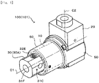
Figure 1 is a perspective view showing an outline of a safety joint according to an embodiment of the present invention; -
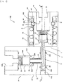
Figure 2 is an explanatory cross sectional view showing a condition that a plug and a socket are connected with each other in the embodiment; -
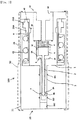
Figure 3 is a cross sectional view taken along the A-A line inFig. 2 ; -
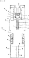
Figure 4 is an explanatory cross sectional view showing a condition that the plug and the socket are separated from each other in the embodiment; -
Figure 5 is a cross sectional view taken along the B-B line inFig. 4 ; -
Figure 6 is a cross sectional view showing a depressurizer in the embodiment; -
Figure 7 is a cross sectional view taken along the C-C line inFig. 6 ; -
Figure 8 is a cross sectional view showing a condition that a risen depressurizing plug allows hydrogen gas to outflow from a hydrogen gas passage to a relief circuit; -
Figure 9 is a cross sectional view showing a condition that a risen depressurizing plug allows hydrogen gas to outflow to a relief circuit in another depressurizer different from that shown inFigs. 6 to 8 ; -
Figure 10 is a perspective view showing the depressurizer shown inFig. 9 ; -
Figure 11 is a perspective view showing a cover according to the embodiment; and -
Figure 12 is a brock diagram showing an outline of a hydrogen filling station. - Hereinafter, an embodiment of the present invention will be explained with reference to the attached drawings. In
Fig. 1 , a whole safety joint according to the embodiment is shown as thenumeral 100, and thesafety joint 100 includes a plug 10 (covered with a cover described below) with a cylindrical shape and asocket 20. When thesocket 20 is connected to the plug 10 (theplug 10 is inserted into the socket 20), opening a shutoff valve to communicate an in-socket passage 21A (refer toFig. 2 etc.) with an in-plug passage 1A (Fig. 2 ). InFig. 1 , theplug 10 and thesocket 20 are connected with each other. Here, theplug 10 is basically connected to a vehicle (not shown in inFig. 1 ) side, and thesocket 20 is basically connected to a hydrogen filling apparatus (or a dispenser, a weighing machine, not shown inFig. 1 ) side. However, it is possible to arrange theplug 10 to the hydrogen filling apparatus side and arrange thesocket 20 to the vehicle side. - Central axes of the in-
plug passage 1A (Fig. 2 ) in theplug 10 and the in-socket passage 21A (Fig. 2 ) in thesocket 20 are orthogonal with each other, and the central axes of the in-plug passage 1A and the in-socket passage 21A do not form a straight line. Constructions and action effects of theplug 10 and thesocket 20 including the in-plug passage 1A, the in-socket passage 21A and the like (in a condition that theplug 10 and thesocket 20 are connected with/separated from each other) will be explained in detail with reference toFigs. 2 to 5 , and to the central axes of the in-plug passage 1A and the in-socket passage 21A are attached C1 and C2 respectively inFig. 1 . InFig. 1 , on an area extending on the vehicle side (left side inFig. 1 ) in the central axis C1 of the in-plug passage 1A is arranged a filling hose not shown, and a hydrogen gas introducing port side (upper side inFig. 1 ) in the central axis C2 of the in-socket passage 21A is connected to a hydrogen filling apparatus not shown. - A
cover 50 is mounted to protect a plug side rod 2 (Figs. 2 to 5 ) mounted to theplug 10, the longitudinal size of thecover 50 is longer than that of theplug side rod 2, and thoroughly surrounds theplug side rod 2. InFig. 1 , thecover 50 surrounds an area from a portion near one end of theplug 10 to another portion near another end of theplug 10 in the central axis C1 direction of the in-plug passage 1A, and thoroughly surrounds theplug side rod 2 mounted in theplug 10. In addition, thecover 50 is attached to theplug 10, and surrounds a portion (lower portion inFig. 1 ) of thesocket 20. Here, thecover 50 is connected to theplug 10 such that thecover 50 does not prevent the separation between theplug 10 and thesocket 20 but thecover 50 is connected to theplug 10 to a degree that thecover 50 does not separate from theplug 10 after theplug 10 and thesocket 20 are separated from each other in an emergency such that a vehicle moves when hydrogen is filled. Meanwhile, thesafety joint 100 is arranged near the hydrogen filling apparatus 200 (Fig. 12 ) and near the base portion of thefilling hose 201. - In
Fig. 1 , on a vehicle side end portion (left end portion inFig. 1 ) of theplug 10 surrounded by thecover 50 is mounted a depressurizer 30 (or 30A). Thedepressurizer 30 is not surrounded by thecover 50, and a plughexagonal hole 32E into which a depressurizing plug formed on an outer side surface of thedepressurizer 30 is exposed inFig. 1 . On a radially central portion of thedepressurizer 30 is formed ahydrogen gas passage 31A (Figs. 6 to 9 ), and thehydrogen gas passage 31A is connected to the in-plug passage 1A (Figs. 2 to 5 ) of theplug 10. On the vehicle side (left side inFig. 1 ) of thedepressurizer 30 is arranged a filling hose not shown. The numeral 31F inFig. 1 indicates a concave portion to which the filling hose on the vehicle side is connected, and the numeral 31C indicates (an outlet of an outer side surface of) a relief circuit in thedepressurizer 30. In addition, the depressurizer 30 (or 30A) will be explained with reference toFigs. 6 to 10 . - Next, the
plug 10 and thesocket 20 of thesafety joint 100 will be explained with reference toFigs. 2 to 5 . Here, thecover 50 explained with reference toFig. 1 is shown by doted lines inFigs. 3 and5 to simplify illustrations, but is deleted inFigs. 2 and4 to avoid complexities in illustrations. InFig. 2 , theplug 10 shaped like a cylinder as a whole body includes a plugmain body 1 and a plugside rod case 3. To a central portion (a vertically central portion inFig. 2 ) of the vehicle side (right side inFig. 2 ) end portion of the plugmain body 1 is mounted a hydrogengas supply port 1B. On the plugmain body 1 is formed the in-plug passage 1A extending in a lateral direction ofFig. 2 , and on the in-plug passage 1A is formed a plug side valveelement accommodating portion 1C. The in-plug passage 1A communicates with a passage in the plugside rod case 3, and communicates through a passage in the plug side valveelement accommodating portion 1C with the hydrogengas supply port 1B. - In the in-
plug passage 1A is accommodated theplug side rod 2, and on an end portion on the side (right side inFig. 2 ) separated from thesocket 20 of theplug side rod 2 is mounted a plugside valve element 6. On the vehicle side (right side inFig. 2 ) of the plugside valve element 6 accommodated in the valveelement accommodating portion 1C is arranged a plug side spring 4, which energizes the plugside valve element 6 toward thesocket 20 side (left side inFig. 2 ). Then, the plugside valve element 6 and avalve seat 1F configure a plugside shutoff valve 5, and the plugside shutoff valve 5 has a function of shutting/opening theplug side passage 1A. An end portion on the opposite side (left side inFig. 2 ) of thevalve element 6 configures a lockingportion 2A. - In
Fig. 2 , on the outside in a radial direction of the hydrogengas supply port 1B of the plugmain body 1 is formed aflange portion 1D. Theflange portion 1D is a connecting surface to the depressurizer 30 (or 30A: refer toFigs. 1 and6 to 10) not shown. Then, when theplug 10 and thesocket 20 are connected with each other, the surface (left side surface of theflange portion 1D inFig. 2 ) of theflange portion 1D on the opposite side to the surface connected to the depressurizer 30 (Fig. 1 ) abuts on aplug accommodating housing 26. On an outer peripheral surface of the plugmain body 1 is formed a connectingchannel 1E, and to the connectingchannel 1E is fitted connectingballs 40 for connecting theplug 10 and thesocket 20 with each other. - The plug
side rod case 3 projects from the plugmain body 1 toward thesocket 20 side (left side inFig. 2 ). On asocket 20 side end portion is shaped aopening portion 21C whose hollow cylindrical shape is closed, and inFigs. 2 and3 in an inner space of theopening portion 21C is accommodated theplug side rod 2. In the outer periphery of the plugside rod case 3, at a predetermined position (corresponding to a lower portion of a socket side rod 22) is formed anopening 3A for passage connection. InFig. 2 , the plugside rod case 3 is inserted into anopening portion 21C of the socket 20 (the socket main body 21), and the in-plug passage 1A and an in-socket passage 21A are communicated with each other through theopening 3A. - In
Fig. 3 , near thesocket 20 side end portion of the plugside rod case 3 is formed alocking ball channel 3B, and in thelocking ball channel 3B are held lockingballs 7. As shown inFig. 3 , by a tapered portion of the lockingportion 2A are pressed the lockingballs 7 radially outward. But, under the condition shown inFig. 3 , by an inner wall surface of theopening portion 21C of thesocket 20, the lockingballs 7 do not move radially outward the plugside rod case 3. On the other hand, as shown inFig. 5 , under a condition that theplug 10 and thesocket 20 are separated from each other, there is no member that prevents the lockingballs 7 from moving radially outward, and the lockingballs 7 position radially outward (the plug side rod case 3). - In
Fig. 2 , thesocket 20 shaped like a cylinder as a whole body has the socketmain body 21 and theplug accommodating housing 26. On a horizontally central portion of a hydrogen filling apparatus side (upper side inFig. 2 ) end portion of the socketmain body 21 is formed a hydrogen gas introducing port 21B. On a horizontally central portion of the socketmain body 21 shown inFig. 2 is formed the in-socket passage 21A extending in the vertical direction, and in a socket side valveelement accommodating portion 21D (enlarged portion) formed on the in-socket passage 21A is accommodated a socketside valve element 25. The in-socket passage 21A communicates from the hydrogen gas introducing port 21B through the socket side valveelement accommodating portion 21D and a hollow portion of thesocket side rod 22, with theopening portion 21C of the socketmain body 21. Here, an end portion on the side separated from theplug 10 of theopening portion 21C is opened. InFigs. 2 and3 , into theopening portion 21C is inserted the plugside rod case 3, and the in-socket passage 21A communicates through the hollow portion of thesocket side rod 22 and theopening 3A of the plugside rod case 3 with the in-plug passage 1A. On the inner periphery of theopening portion 21C of the socketmain body 21 are mounted O-rings SS1, SS2. - To the socket
side valve element 25 is connected thesocket side rod 22. On the side of the hydrogen gas introducing port 21B (upper side inFig. 2 ) of the socketside valve element 25 is arranged asocket side spring 23, and thesocket side spring 23 energizes the socketside valve element 25 toward avalve seat 21E (lower side inFig. 2 ). Then, thevalve element 25 and thevalve seat 21E configure a socketside shutoff valve 24, which has a function of shutting/opening thesocket side passage 21A. A hydrogen gas fed to the valveelement accommodating portion 21D inflows through theopenings 22A formed on thesocket side rod 22 to the hollow portion of thesocket side rod 22. Here, the hollow portion of thesocket side rod 22 configures a portion of the in-socket passage 21A. - The
plug accommodating housing 26 whose end portion is opened projects from the socketmain body 21 toward the plug 10 (right side inFig. 2 ). On the inner peripheral surface of theplug accommodating housing 26 are formed at-connection arrangement portions 26A and an at-disconnection accommodating channel 26B. On the at-connection arrangement portions 26A are arranged the connectingballs 40 when theplug 10 and thesocket 20 are connected with each other, and in the at-disconnection accommodating channel 26B are accommodated the connectingballs 40 moved from the at-connection arrangement portions 26A when from thesocket 20 is disconnected theplug 10. The horizontal (lateral inFig. 2 ) position of the at-connection arrangement portions 26A corresponds to that of the plugside connecting channel 1E of the plugmain body 1. In addition, on the side of the socket 20 (left side inFig. 2 ) of the at-connection arrangement portions 26A is formed a projection α projecting from the at-connection arrangement portions 26A inwardly in a radial direction of theplug 10. - When hydrogen gas is filled, the
main body 1 of theplug 10 is inserted into theplug accommodating housing 26, and by the connectingballs 40 and the connectingspring 41 are integrally connected theplug 10 and thesocket 20 with each other. As shown inFig. 2 , when theplug 10 and thesocket 20 are connected with each other, thespring holder 42 to which the connectingspring 41 is attached positions in a gap between the inner peripheral surface of theplug accommodating housing 26 and the outer peripheral surface of the plugmain body 1. The connectingballs 40 are fitted into connectingball holes 42A formed on thespring holder 42, and engage with the plugside connecting channel 1E of the plugmain body 1. At this time, on thesocket 20 side of the connecting balls 40 (left side inFig. 1 ) positions the projection α, and in the radially outward direction of the connectingballs 40 position the at-connection arrangement portions 26A. Thespring holder 42 engages with theplug 10 through the connectingballs 40 and the plugside connecting channel 1E into which the connectingballs 40 are fitted. Therefore, when theplug 10 and thesocket 20 are connected with each other, theplug 10 and thesocket 20 are integrated with each other so as to hold thespring holder 42 and the connectingballs 40 in between. - In
Fig. 2 , when a force pulling out the plug 10 (a tensile force for separating from the socket 20: a force moving theplug 10 rightward inFig. 2 ) is applied, through the connectingballs 40, thespring holder 42 and the connectingspring 41 try to move in a direction apart from the socket 20 (right side inFig. 2 ). Unless more or equal to predetermined magnitude of force for pulling out theplug 10 is applied thereto, even if to the connectingballs 40 are applied the forces shown as the allows M inFig. 2 , the forces are weakened by the elastically repulsive force by the connectingspring 41, and a condition that connectingballs 40 are fitted into the plugside connecting channel 1E is maintained, which does not release the connection between theplug 10 and thesocket 20. On the other hand, when more or equal to predetermined magnitude of force for pulling out theplug 10 is applied thereto, the connectingballs 40 disengaged from the plugside connecting channel 1E and move in the arrow M directions, and as show inFig. 4 , the connectingballs 40 are fitted into the at-disconnection accommodating channel 26B (Fig. 2 ) of theplug accommodating housing 26. Then, theplug 10 is disconnected from thesocket 20, resulting in a disjoint condition shown inFigs. 4 and5 . Here, the predetermined value (boundary value that the joint between theplug 10 and thesocket 20 is released) is determined based on specifications of the hydrogen filling apparatus, the filling hose and the like, and based on the predetermined value are designed theplug 10 and theplug accommodating housing 26, the connectingballs 40, the connectingspring 41 and thespring holder 42 of thesocket 20. - As shown in
Fig. 2 , under a condition theplug 10 and thesocket 20 are connected with each other, the lower end portion (Fig. 2 ) of the hollowsocket side rod 22 abuts on the plugside rod case 3, so that thesocket side rod 22 positions, against the elastically repulsive force of thesocket side spring 23, on an upper portion from thevalve seat 21E inFig. 2 , and the socketside shutoff valve 24 opens. In addition, as shown inFig. 3 , theplug side rod 2 that cannot move leftward from the lockingballs 7 separates, against the elastically repulsive force of the plug side spring 4, the plugside valve element 6 from the plugside valve seat 1F. As a result, the plugside shutoff valve 5 opens. When both of the socketside shutoff valve 24 in thesocket 20 and the plugside shutoff valve 5 in theplug 10 become open, the in-socket passage 21A (the hydrogen gas introducing port 21B, the socket side valveelement accommodating portion 21D, the hollow portion of thesocket side rod 22 and theopening portion 21C of the socket 20) and the in-plug passage 1A (the hollow portion of the plugside rod case 3, the plug side valveelement accommodating portion 1C) are communicated with each other, and from the side of the hydrogen filling apparatus (weighing machine) to the side of the vehicle flows hydrogen gas. - At an emergency such as vehicle starts while hydrogen gas filling, a tensile force more or equal to a predetermined magnitude is applied to the filling hose so as to detach the connecting
balls 40 from the plugside connecting channel 1E, theplug 10 and thesocket 20 are disconnected from each other. When theplug 10 and thesocket 20 are disconnected from each other, as shown inFig. 4 , the plugside rod case 3 of theplug 10 is detached from theopening portion 21C of the socket 20 (socket main body 21), and the socketside valve element 25 moves downward inFig. 4 by an elastically repulsive force of thesocket side spring 23. As a result, the socketside valve element 25 seats on the socketside valve seat 21E, and the socketside shutoff valve 24 shuts the in-socket passage 21A. In addition, as shown inFig. 5 , when the lockingballs 7 move outward the plugside rod case 3 in a radial direction from the lockingball channel 3B, the lockingportion 2A (Fig. 2 ) of theplug side rod 2 moves leftward from the lockingballs 7 by the elastically repulsive force of the plug side spring 4. As a result, the plugside valve element 6 seats on the plugside valve seat 1F, and the plugside shutoff valve 5 shuts the in-plug passage 1A. Since the socketside shutoff valve 24 and the plugside shutoff valve 5 close the in-socket passage 21A and the in-plug passage 1A respectively, hydrogen gas does not leak from vehicle side and hydrogen filling apparatus side. - As explained with reference to
Fig. 1 , thecover 50 is mounted to protect theplug side rod 2, thecover 50 covering theplug 10 and a portion of thesocket 20. Thecover 50 is expressed with dashed lines inFigs. 3 and5 . As shown inFig. 5 , when theplug 10 and thesocket 20 are disconnected from each other, thecover 50 attached to theplug 10 side separates from thesocket 20. A length of thecover 50 is long in a longitudinal direction of theplug side rod 2, and thecover 50 is configured such that perfectly covering theplug side rod 2. Therefore, even if theplug 10 and thesocket 20 are separated from each other, and theplug 10 falls or collides with the hydrogen filling apparatus or the like, theplug side rod 2 is protected by thecover 50. - In the socket 20 (socket main body 21) of the safety joint 100 shown in
Figs. 2 to 5 , the end portion opposite to theplug 10 side (left side inFig. 2 ) of theopening portion 21C in which the plugside rod case 3 is inserted opens to be a through hole. But, in theopening portion 21C, the end portion opposite to theplug 10 side (left side inFig. 2 ) can be closed to be a blind hole. In this case, the O-ring SS2 is not required. - Next, the depressurizer 30 (or 30A) will be explained with reference to
Figs. 6 to 10 . Thedepressurizer 30 is, as shown inFig. 1 for example, attached to theplug 10 of thesafety joint 100, and has a function of depressurizing high pressure hydrogen gas in an area on the vehicle side from the plug 10 (in-plug passage 1A,Figs. 2 to 5 ) when theplug 10 and thesocket 20 are separated from each other. In addition, high pressure hydrogen gas in an area on the hydrogen filling apparatus side from thesocket 20 is depressurized by a depressurizing mechanism not shown on the hydrogen filling apparatus side. - In
Fig. 6 , thedepressurizer 30 has a metal depressurizer main body portion (hereinafter referred to as "main body portion") 31 with a nearly rectangular parallelepiped shape and ametal depressurizing plug 32, and the depressurizingplug 32 is configured to engage with (screw to) a depressurizingcommunication hole 31B of themain body portion 31. On the left side of themain body portion 31 is formed a projectingportion 31E, and the projectingportion 31E is connected to theplug 10 side of thesafety joint 100. On the right side of themain body portion 31 is formed aconcaved portion 31F, and to theconcaved portion 31F is connected the vehicle side filling hose (Fig. 12 ). However, it is possible that the projectingportion 31E is connected to the vehicle side filling hose, and theconcaved portion 31F is connected to theplug 10 side of thesafety joint 100. On a central portion in a vertical direction of themain body portion 31 inFig. 6 is formed ahydrogen gas passage 31A, and thehydrogen gas passage 31A communicates through the projectingportion 31E with the in-plug passage 1A on theplug 10 side and communicates through theconcaved portion 31F with the vehicle side filling hose. - In
Fig. 6 , the depressurizingcommunication hole 31B communicating from anupper surface 31G with thehydrogen gas passage 31A extends in a vertical direction, and with the depressurizingcommunication hole 31B communicates arelief circuit 31C (refer toFigs. 7 and8 : not shown inFig. 6 ). A cross sectional area of therelief circuit 31C is set small to be enough to add a sufficient pressure loss to a flowing hydrogen gas. Into the depressurizingcommunication hole 31B is fitted the depressurizingplug 32, and as shown inFig. 7 , engagement of the depressurizingplug 32 and the depressurizingcommunication hole 31B shuts therelief circuit 31C from thehydrogen gas passage 31A. - The depressurizing
communication hole 31B has a small diameter portion 31BA communicating with thehydrogen gas passage 31A, a tapered portion 31BB, the first middle diameter portion 31BC, the second middle diameter portion 31BD, and a female screw portion 31BE communicating with theupper surface 31G. The depressurizingplug 32 has apin end portion 32A with a minimum diameter in a lower end portion, a pin taperedportion 32B, a pinmiddle diameter portion 32C, amale screw portion 32D forming a male screw on an outer periphery. When the depressurizingplug 32 is fitted into the depressurizingcommunication hole 31B, thepin end portion 32A of the depressurizingplug 32 is inserted into the small diameter portion 31BA of the depressurizingcommunication hole 31B. - As shown in
Fig. 6 , the pin taperedportion 32B of the depressurizingplug 32 and the tapered portion 31BB of the depressurizingcommunication hole 31B are complementary shapes with each other, and the pin taperedportion 32B contacts the tapered portion 31BB. Here, the depressurizingplug 32 and themain body portion 31 are made of metal, so that a portion where the pin taperedportion 32B and the tapered portion 31BB contact with each other configures a so-called "metal seal". Between the pinmiddle diameter portion 32C of the depressurizingplug 32 and the second middle diameter portion 31BD of the pressurizingcommunication hole 31B is arranged an O-ring 31H, and the O-ring 31H prevents high pressure hydrogen gas from injecting upward from a gap between the depressurizingplug 32 and the depressurizingcommunication hole 31B when the depressurizingplug 32 sufficiently moves relative to (rises against: refer toFig. 6 ) the depressurizingcommunication hole 31B (in a condition that engagement between the depressurizingplug 32 and themain body portion 31 is released: refer toFig. 8 ). To the female screw portion 31BE of the depressurizingcommunication hole 31B screws a male screw formed on the outer periphery of themale screw portion 32D of the depressurizingplug 32. On an upper surface of the depressurizingplug 32 is formed a plughexagonal hole 32E, and a hexagonal rod spanner S is inserted into the plughexagonal hole 32E to be rotated as shown inFig. 10 when the depressurizingplug 32 is attached to/detached from the depressurizingcommunication hole 31B. - As shown in
Figs. 7 and8 , in an area near a boundary between the tapered portion 31BB and the first middle diameter portion 31BC, the depressurizingcommunication hole 31B communicates with therelief circuit 31C. As shown inFigs. 6 and 7 , in a condition that the depressurizingplug 32 is tightened to the depressurizingcommunication hole 31B (in a condition that hydrogen is filled without separation of the safety joint 100), the pin taperedportion 32B and the tapered portion 31BB of the depressurizingcommunication hole 31B contact with each other to configure the metal seal, so that high pressure hydrogen gas flowing in thehydrogen gas passage 31A is completely shut by the metal seal and does not flow into therelief circuit 31C. On the other hand, in case that thesafety joint 100 is separated, when high pressure hydrogen gas existing in an area on the vehicle side from the plug 10 (in-plug passage 1A shown inFigs. 2 to 5 ) is discharged as depressureizing, the depressurizingplug 32 is rotated in a depressurizing direction by the hexagonal rod spanner S, the engagement between the female screw portion 31BE of the depressurizingcommunication hole 31B and themale screw portion 32D of the depressurizingplug 32 is released, the pin taperedportion 32B and the tapered portion 31BB of the depressurizingcommunication hole 31B are separated from each other, and the metal seal is released. - A condition that the metal seal is released is shown in
Fig. 8 . A diameter size ϕ of thepin end portion 32A is set slightly smaller than the inner diameter d of the small diameter portion 31BA of the depressurizingcommunication hole 31B (ϕ<d), and between an outer periphery of thepin end portion 32A and an inner periphery of the small diameter portion 31BA of the depressurizingcommunication hole 31B is formed an annular gap whose cross sectional area is (π/4)(d2-ϕ2). When the depressurization is performed, high pressure hydrogen gas filled in thehydrogen gas passage 31A inflows through the annular gap into therelief circuit 31C and passes through therelief circuit 31C to outflow from thedepressurizer 30 as shown by the arrow θ. Here, a hydrogen gas outlet of therelief circuit 31C is formed at a position apart from the plughexagonal hole 32E. - In
Figs. 6 to 8 , as shown inFig. 7 for example, in a condition the depressurizingplug 32 is tightened to the depressurizingcommunication hole 31B, a length L of thepin end portion 32A (vertical length inFig. 7 ) and a length HL of the small diameter portion 31BA of the depressurizingcommunication hole 31B are relatively long, and a length LW of thepin end portion 32A inserted into the small diameter portion 31BA of the depressurizingcommunication hole 31B is relatively long also. Therefore, even if the hexagonal rod spanner S is excessively rotated in the plughexagonal hole 32E, thepin end portion 32A will not be completely separated from the small diameter portion 31BA of the depressurizingcommunication hole 31B, a condition that the hydrogen gas passes through the annular gap between the small diameter portion 31BA and thepin end portion 32A (cross sectional area is (π/4)(d2-ϕ2)) is maintained, and pressure loss can be applied to the high pressure hydrogen gas. - In
Figs. 9 and10 is shown adepressurizer 30A different from thedepressurizer 30 shown inFigs. 6 to 8 . The length L (vertical length inFig. 9 ) of thepin end portion 32A of theplug 32 is clearly shorter than that of thedepressurizer 30 shown inFig. 7 , and the length LW (refer to thedepressurizer 30 shown inFig. 7 ) of thepin end portion 32A inserted into the small diameter portion 31BA is shorter than that also. Therefore, when in depressurizing shown inFig. 9 , into the plughexagonal hole 32E is inserted the hexagonal rod spanner S, and the hexagonal rod spanner S is excessively rotated, there is a possibility that from the small diameter portion 31BA of the depressurizingcommunication hole 31B is completely separated thepin end portion 32A of theplug 32; cross sectional area of a gap between the depressurizingcommunication hole 31B and theplug 32 becomes large; the gap does not work as an orifice; and velocity of the hydrogen gas outflowing from therelief circuit 31C increases. - Therefore, in the
depressurizer 30A, as shown inFigs. 9 and10 , on theupper surface 31G of themain body portion 31 is formed a lockingpin insertion hole 31D, and into the lockingpin insertion hole 31D is insertable a locking pin P for suppressing rotation of the hexagonal rod spanner S. By the locking pin P, excessive rotation of the hexagonal rod spanner S is suppressed, and a condition that the gap between thepin end portion 32A of theplug 32 and the small diameter portion 31BA of the depressurizingcommunication hole 31B exists is maintained, which functions to generate a pressure loss in hydrogen gas. In addition, inFig. 10 , the arrow D indicates the filling hose on the vehicle side, and the arrow E indicates theplug 10 side in thesafety joint 100. In addition, thedepressurizer 30 shown inFigs. 6 to 8 also, the locking pin P and the lockingpin insertion hole 31D can be mounted to prevent the excessive rotation of the hexagonal rod spanner S. InFigs. 9 and10 , to the same members as those shown inFigs. 6 to 8 are attached the same numerals as those, and overlapped explanation is omitted. Then, other construction and action effect of thedepressurizer 30A shown inFigs. 9 and10 are the same as those of thedepressurizer 30. - In
Fig 11 , thecover 50 is integrally constituted by metal members, and has amain body portion 50A with a cylindrical shape and a socket insertedportion 50B. As shown inFig. 1 , themain body portion 50A of thecover 50 covers the plugmain body 1 and the plug accommodating housing 26 (refer toFig. 2 etc.) of thesocket 20, and the socket insertedportion 50B covers the plug siderod accommodating case 3 and the plug side rod 2 (Figs. 2 to 4 ). In aspace portion 50C of the socket insertedportion 50B is accommodated a connected portion of theplug 10 and thesocket 20, the connected portion positioning lower side of thesocket 20. - Although not clearly shown in figures, the
cover 50 is attached to theplug 10 by a conventionally known method. Thecover 50 is mounted to protect theplug side rod 2 when theplug 10 and thesocket 20 are separated from each other, so that thecover 50 surrounds thesocket 20 side such that the separation between thesocket 20 and theplug 10 are not prevented. An end portion opposite to the socket insertedportion 50B (left side inFig. 11 ) in themain body portion 50A of thecover 50 has anopening 50D. As described above, the plugmain body 1 is connected through the depressurizer 30 (or 30A) to the vehicle side (refer toFig. 1 ). - With the safety joint 100 according to the embodiment shown in the figures, the
cover 50 is mounted to completely surround the plug side rod 2 (valve rod) mounted on theplug 10 and/or the plug siderod accommodating case 3 including the longitudinal directions thereof, so that it is prevented that theplug side rod 2 is broken because impacts are not directly acted on theplug side rod 2 even if theplug 10 falls or collides with the hydrogen filling apparatus or the vehicle in case that theplug 10 and thesocket 20 are separated from each other in an emergency when the vehicle runs while hydrogen is filled. In addition, thecover 50 is securely attached to theplug 10 side, and covers thesocket 20 side such that separation of the socket is not prevented, so that it maintains that thecover 50 covers theplug side rod 2, and thecover 50 separates from thesocket 20 side when theplug 10 and thesocket 20 are separated from each other. Therefore, theplug side rod 2 can be surely protected. - In addition, in the embodiment shown in the figures, the
safety joint 100 is arranged near the hydrogen filling apparatus (weighing machine) and near a base portion of the filling hose communicating with the filling nozzle, so that thesafety joint 100 is supported by the hydrogen filling apparatus, and weight of the hose does not increase. Therefore, there is no possibility that it becomes difficult for filling workers to handle the hose. - In the embodiment shown in the figures, central axes of the in-
plug passage 1A and the in-socket passage 1A do not form a straight line, and are orthogonal with each other, so that central axes of theplug side rod 2 and thesocket side rod 22 do not form a straight line also, theplug side rod 2 and thesocket side rod 22 are not pressed with each other under a condition that end portions (pin connecting end portions) contact with each other. Therefore, even if high pressure hydrogen gas is fed, forces that push end portions of thesocket side rod 22 and theplug side rod 2 with each other do not increase, and thesocket 20 and theplug 10 are not separated from each other. Then, the end portions of thesocket side rod 22 and theplug side rod 2 do not press with each other, and directions that thesocket 20 and theplug 10 are separated from each other are different from each other, so that the separatedsocket 20 and plug 10 are not blown off. Further, thesafety joint 100 can be made small in size and light in weight, and operability when hydrogen gas is filled improves. - In addition, in the embodiment shown in the figures, the
plug 10 and thesocket 20 are connected with each other by the connecting balls (connecting members) 40 radially mounted at plurality of portions, so that a condition that theplug 10 and thesocket 20 are connected with each other is surely maintained. Then, the connectingballs 40 are configured to release the connection when an external force in a separating direction more or equal to a predetermined value acts on the connectingballs 40, so that the external force acting on the filling hose (tensile force acting on the filling hose when the vehicle runs while hydrogen is filled) separates theplug 10 and thesocket 20 from each other regardless of pressures in the passages in theplug 10 and thesocket 20. - In the embodiment shown in the figures, when the
plug 10 and thesocket 20 are separated from each other, the socket side shut offvalve 24 and the plug side shut offvalve 5 are surely closed. Therefore, when theplug 10 and thesocket 20 are separated from each other, it is prevented that hydrogen gas outflows. - In addition, in the embodiment shown in the figures, since the
depressurizers plug 10, when theplug 10 and thesocket 20 are separated from each other for example, high pressure hydrogen gas in the filling hose can be discharged at small flow rate and low pressure outside the filling hose (outside thedepressurizers - In the
depressurizers portion 32B of the depressurizingplug 32 and the tapered portion 31BB of the depressurizingcommunication hole 31B contact with each other configures metal seal to completely shut high pressure hydrogen gas flowing in thehydrogen gas passage 31A. Then, at the depressurizing, when the contact of the taperedportions 32B , 31BB is released, the gap (cross sectional area (π/4)(d2-ϕ2), annular gap) formed between an outer periphery of the hydrogen passage side end portion (32A: pin end portion, diameter size "ϕ") of the depressurizingplug 32 and inner periphery of the hydrogen passage side end portion (31BA: small diameter portion, inner diameter "d") of the depressurizingcommunication hole 31B works as an orifice, and imparts pressure loss to high pressure hydrogen gas flowing through the orifice, so that injecting velocity of hydrogen gas outflowing from thedepressurizers - In addition, the
relief circuit 31C for outflowing hydrogen gas is formed, and the hydrogen gas outlet of therelief circuit 31C is formed at a position apart from an area above the depressurizingplug 32. Then, even if sparks generate by contacts between metals when the hexagonal rod spanner S is inserted into the plughexagonal hole 32E mounted on the upper portion of theplug 32 to be rotated, a possibility that the hydrogen gas catches fire due to the sparks becomes extremely low, and safety thereof improves. - Since the embodiments shown in the drawings are merely examples, and the embodiments do not limit the technical scope of the present invention.
-
- 1 plug main body
- 1A in-plug passage
- 2 plug side rod
- 10 plug
- 20 socket
- 21 socket main body
- 21A in-socket passage
- 30, 30A depressurizers
- 31 main body portion
- 31A hydrogen gas passage
- 31B depressurizing communication hole
- 31BA small diameter portion
- 31BB tapered portion
- 31C relief circuit
- 31D locking pin insertion hole
- 32 depressurizing plug
- 32A pin end portion
- 32B pin tapered portion
- 50 cover
- 100 safety joint
- HL length of depressurizing communication hole
- L length of small diameter portion
- P locking pin
- S hexagonal rod spanner
Claims (3)
- A safety joint (100) comprising a plug (10) with a cylindrical shape in which a passage (1A) is formed, a socket (20) in which a passage (21A) continuing to the passage (1A) in the plug (10) is formed, and a shut off valve (24) mounted on the passage (21A) in the socket (20), the shut off valve (24) opening when the plug (10) being inserted into the socket (20) and closing when the plug (10) being disconnected therefrom,
wherein central axes of the passages (21A) of the plug (10) and the socket (20) do not form a straight line, characterised in that the safety joint further comprises a cover (50) for protecting a valve rod (2) mounted on the plug (10), wherein the cover (50) surrounds an area from a portion near one end of the plug (10) to another portion near another end of the plug (10) in the central axis (C1) direction of the in-plug passage (1A), and surrounds the valve rod (2), wherein the cover (50) is attached to the plug (10), and surrounds a portion of the socket (20) when the plug (10) is inserted into the socket, and wherein the cover (50) is connected to the plug (10) such that the cover (50) does not separate from the plug (10) after the plug (10) and the socket (20) are separated from each other. - The safety joint as claimed in claim 1, wherein one of the plug (10) and the socket (20) comprises a depressurizer (30, 30A) including a main body portion (31) made of metal, a depressurizing communication hole (31B) communicating with a hydrogen gas passage (21A) in the main body portion (31), a depressurizing plug (10) made of metal, the depressurizing plug (10) insertable into the depressurizing communication hole (31B), and tapered portions (32B, 31BB) formed on the depressurizing communication hole (31B) and the depressurizing plug (10) respectively, the tapered portions (32B, 31BB) having complemental shapes with each other.
- The safety joint as claimed in claim 2, further comprising a relief circuit (31C) for outflowing a filled fluid and communicating with the depressurizing communication hole (31B), an outlet of the relief circuit (31C) being formed at a position separated from an area above the depressurizing plug (10).
Applications Claiming Priority (1)
| Application Number | Priority Date | Filing Date | Title |
|---|---|---|---|
| JP2017135273A JP6604487B2 (en) | 2017-07-11 | 2017-07-11 | Pipe fitting |
Publications (2)
| Publication Number | Publication Date |
|---|---|
| EP3428502A1 EP3428502A1 (en) | 2019-01-16 |
| EP3428502B1 true EP3428502B1 (en) | 2019-09-04 |
Family
ID=62841978
Family Applications (1)
| Application Number | Title | Priority Date | Filing Date |
|---|---|---|---|
| EP18181171.2A Active EP3428502B1 (en) | 2017-07-11 | 2018-07-02 | Safety joint |
Country Status (6)
| Country | Link |
|---|---|
| US (1) | US10598294B2 (en) |
| EP (1) | EP3428502B1 (en) |
| JP (1) | JP6604487B2 (en) |
| KR (1) | KR102096899B1 (en) |
| CN (1) | CN109237180B (en) |
| RU (1) | RU2765853C2 (en) |
Cited By (1)
| Publication number | Priority date | Publication date | Assignee | Title |
|---|---|---|---|---|
| WO2023144598A1 (en) * | 2022-01-28 | 2023-08-03 | Barun Kumar Bhoumik | Sealing mechanism for boss part assembly of composite cylinder and method thereof |
Families Citing this family (7)
| Publication number | Priority date | Publication date | Assignee | Title |
|---|---|---|---|---|
| JP6590159B2 (en) * | 2017-07-11 | 2019-10-16 | 株式会社タツノ | Safety fitting |
| JP7205780B2 (en) * | 2020-11-24 | 2023-01-17 | 株式会社タツノ | safety fittings |
| JP7300111B2 (en) * | 2021-01-06 | 2023-06-29 | 株式会社タツノ | safety fittings |
| JP7276721B2 (en) * | 2021-01-14 | 2023-05-18 | 株式会社タツノ | safety fittings |
| JP7372606B2 (en) * | 2022-01-05 | 2023-11-01 | 株式会社タツノ | safety fittings |
| JP7614567B2 (en) * | 2023-03-31 | 2025-01-16 | 株式会社タツノ | Support structure for filling nozzle |
| WO2025074602A1 (en) * | 2023-10-06 | 2025-04-10 | 日立Astemo株式会社 | Coupler and hydraulic equipment using coupler |
Family Cites Families (24)
| Publication number | Priority date | Publication date | Assignee | Title |
|---|---|---|---|---|
| FR1557750A (en) * | 1967-11-30 | 1969-02-21 | ||
| MX151632A (en) * | 1980-02-15 | 1985-01-23 | Gould Inc | IMPROVEMENTS TO BURST PROTECTOR FOR HIGH PRESSURE HOSES |
| US4617975A (en) * | 1982-07-23 | 1986-10-21 | Charles Rabushka | Tension actuated uncoupler |
| SU1151749A1 (en) * | 1983-08-10 | 1985-04-23 | Винницкий политехнический институт | Check safety valve |
| JPS6099372U (en) * | 1983-12-13 | 1985-07-06 | 日立建機株式会社 | Air bleed plug |
| JPH0450800U (en) * | 1990-09-07 | 1992-04-28 | ||
| JP2848203B2 (en) * | 1993-08-25 | 1999-01-20 | 株式会社タツノ・メカトロニクス | Safety fittings |
| JP3339611B2 (en) * | 1996-01-11 | 2002-10-28 | 株式会社タツノ・メカトロニクス | Safety fittings |
| JP3298097B2 (en) * | 1996-01-12 | 2002-07-02 | 株式会社タツノ・メカトロニクス | Cover of safety fitting of weighing machine |
| DE10061653C1 (en) * | 2000-12-11 | 2002-01-31 | Mertik Maxitrol Gmbh & Co Kg | Gas plug has housing with inlet pipe, outlet socket, shutoff device, cap covering opening, cover and lock |
| JP2003113983A (en) * | 2001-10-01 | 2003-04-18 | Sony Corp | Fluid connector device |
| RU2283452C1 (en) * | 2005-03-09 | 2006-09-10 | Сергей Юрьевич Горохов | Pipeline quick-release coupling |
| JP2007120717A (en) * | 2005-10-31 | 2007-05-17 | Hitachi Ltd | Emergency disconnect coupling |
| JP2010078027A (en) * | 2008-09-25 | 2010-04-08 | Nagano Yuki Kk | Piping joint |
| GB0904805D0 (en) * | 2009-03-20 | 2009-05-06 | Erwin Alexander | Valve assembly |
| US8485235B2 (en) * | 2009-06-19 | 2013-07-16 | Piramal Critical Care, Inc. | Receiver with valves |
| CN201875329U (en) * | 2010-11-24 | 2011-06-22 | 徐洪才 | Anti-theft and antifreeze quick joint |
| CN102128329A (en) * | 2011-03-10 | 2011-07-20 | 庄志军 | Plunger type pneumatic quick change coupler |
| CN102297302A (en) * | 2011-08-05 | 2011-12-28 | 庄志军 | Plunger type pneumatic fast-changing connector |
| US8931499B2 (en) * | 2011-11-23 | 2015-01-13 | Opw Fueling Components Inc. | Ball and socket breakaway connector |
| JP5872283B2 (en) * | 2011-12-27 | 2016-03-01 | Kyb株式会社 | Pressure relief valve |
| DE102012004515A1 (en) * | 2012-03-06 | 2013-09-12 | Beda Oxygentechnik Armaturen-GmbH | Lance holder with fuse for odd, especially bent oxygen lances |
| CN103075598A (en) * | 2013-01-22 | 2013-05-01 | 苏州市捷达消防车辆装备有限公司 | Water outlet joint structure of fire pump |
| CN205026267U (en) * | 2015-10-09 | 2016-02-10 | 河南城建学院 | Quick shut -off valve of pressure type |
-
2017
- 2017-07-11 JP JP2017135273A patent/JP6604487B2/en active Active
-
2018
- 2018-07-02 EP EP18181171.2A patent/EP3428502B1/en active Active
- 2018-07-06 KR KR1020180078687A patent/KR102096899B1/en active Active
- 2018-07-09 RU RU2018124976A patent/RU2765853C2/en active
- 2018-07-10 CN CN201810748802.9A patent/CN109237180B/en active Active
- 2018-07-10 US US16/031,901 patent/US10598294B2/en active Active
Non-Patent Citations (1)
| Title |
|---|
| None * |
Cited By (1)
| Publication number | Priority date | Publication date | Assignee | Title |
|---|---|---|---|---|
| WO2023144598A1 (en) * | 2022-01-28 | 2023-08-03 | Barun Kumar Bhoumik | Sealing mechanism for boss part assembly of composite cylinder and method thereof |
Also Published As
| Publication number | Publication date |
|---|---|
| EP3428502A1 (en) | 2019-01-16 |
| RU2765853C2 (en) | 2022-02-03 |
| CN109237180A (en) | 2019-01-18 |
| US10598294B2 (en) | 2020-03-24 |
| RU2018124976A (en) | 2020-01-09 |
| KR20190006915A (en) | 2019-01-21 |
| RU2018124976A3 (en) | 2021-09-10 |
| CN109237180B (en) | 2021-08-31 |
| JP6604487B2 (en) | 2019-11-13 |
| JP2019015390A (en) | 2019-01-31 |
| KR102096899B1 (en) | 2020-04-06 |
| US20190017616A1 (en) | 2019-01-17 |
Similar Documents
| Publication | Publication Date | Title |
|---|---|---|
| EP3428502A1 (en) | Safety joint | |
| EP3431853B1 (en) | Safety joint | |
| US10274118B2 (en) | Pipe joint having releasably engageable plug and socket | |
| EP3428500B1 (en) | Safety joint | |
| EP3324096B1 (en) | Filling device | |
| US8726923B2 (en) | Safety valve | |
| AU2014289979B2 (en) | Tool and method for draining a fire sprinkler system and a fire sprinkler | |
| CN104797870A (en) | Valve assembly | |
| US10641425B2 (en) | Depressurizer | |
| EP4001725B1 (en) | Pipe joint | |
| KR102491391B1 (en) | Couplings for transmission of fluids, methods for closing fluid channels of such couplings and preferred uses of such couplings | |
| US7757712B2 (en) | Coupling device for a compressed gas cylinder | |
| EP4030093B1 (en) | Safety joint |
Legal Events
| Date | Code | Title | Description |
|---|---|---|---|
| PUAI | Public reference made under article 153(3) epc to a published international application that has entered the european phase |
Free format text: ORIGINAL CODE: 0009012 |
|
| STAA | Information on the status of an ep patent application or granted ep patent |
Free format text: STATUS: THE APPLICATION HAS BEEN PUBLISHED |
|
| AK | Designated contracting states |
Kind code of ref document: A1 Designated state(s): AL AT BE BG CH CY CZ DE DK EE ES FI FR GB GR HR HU IE IS IT LI LT LU LV MC MK MT NL NO PL PT RO RS SE SI SK SM TR |
|
| AX | Request for extension of the european patent |
Extension state: BA ME |
|
| STAA | Information on the status of an ep patent application or granted ep patent |
Free format text: STATUS: REQUEST FOR EXAMINATION WAS MADE |
|
| 17P | Request for examination filed |
Effective date: 20190130 |
|
| RBV | Designated contracting states (corrected) |
Designated state(s): AL AT BE BG CH CY CZ DE DK EE ES FI FR GB GR HR HU IE IS IT LI LT LU LV MC MK MT NL NO PL PT RO RS SE SI SK SM TR |
|
| GRAP | Despatch of communication of intention to grant a patent |
Free format text: ORIGINAL CODE: EPIDOSNIGR1 |
|
| STAA | Information on the status of an ep patent application or granted ep patent |
Free format text: STATUS: GRANT OF PATENT IS INTENDED |
|
| RIC1 | Information provided on ipc code assigned before grant |
Ipc: B67D 7/32 20100101ALI20190503BHEP Ipc: F16L 57/00 20060101ALI20190503BHEP Ipc: F16L 55/10 20060101AFI20190503BHEP Ipc: F16K 17/20 20060101ALI20190503BHEP |
|
| INTG | Intention to grant announced |
Effective date: 20190521 |
|
| GRAS | Grant fee paid |
Free format text: ORIGINAL CODE: EPIDOSNIGR3 |
|
| GRAA | (expected) grant |
Free format text: ORIGINAL CODE: 0009210 |
|
| STAA | Information on the status of an ep patent application or granted ep patent |
Free format text: STATUS: THE PATENT HAS BEEN GRANTED |
|
| AK | Designated contracting states |
Kind code of ref document: B1 Designated state(s): AL AT BE BG CH CY CZ DE DK EE ES FI FR GB GR HR HU IE IS IT LI LT LU LV MC MK MT NL NO PL PT RO RS SE SI SK SM TR |
|
| REG | Reference to a national code |
Ref country code: GB Ref legal event code: FG4D |
|
| REG | Reference to a national code |
Ref country code: CH Ref legal event code: EP |
|
| REG | Reference to a national code |
Ref country code: AT Ref legal event code: REF Ref document number: 1175831 Country of ref document: AT Kind code of ref document: T Effective date: 20190915 |
|
| REG | Reference to a national code |
Ref country code: DE Ref legal event code: R096 Ref document number: 602018000566 Country of ref document: DE |
|
| REG | Reference to a national code |
Ref country code: IE Ref legal event code: FG4D |
|
| REG | Reference to a national code |
Ref country code: CH Ref legal event code: NV Representative=s name: NOVAGRAAF INTERNATIONAL SA, CH |
|
| REG | Reference to a national code |
Ref country code: SE Ref legal event code: TRGR |
|
| REG | Reference to a national code |
Ref country code: NL Ref legal event code: MP Effective date: 20190904 |
|
| REG | Reference to a national code |
Ref country code: LT Ref legal event code: MG4D Ref country code: NO Ref legal event code: T2 Effective date: 20190904 |
|
| PG25 | Lapsed in a contracting state [announced via postgrant information from national office to epo] |
Ref country code: LT Free format text: LAPSE BECAUSE OF FAILURE TO SUBMIT A TRANSLATION OF THE DESCRIPTION OR TO PAY THE FEE WITHIN THE PRESCRIBED TIME-LIMIT Effective date: 20190904 Ref country code: HR Free format text: LAPSE BECAUSE OF FAILURE TO SUBMIT A TRANSLATION OF THE DESCRIPTION OR TO PAY THE FEE WITHIN THE PRESCRIBED TIME-LIMIT Effective date: 20190904 Ref country code: BG Free format text: LAPSE BECAUSE OF FAILURE TO SUBMIT A TRANSLATION OF THE DESCRIPTION OR TO PAY THE FEE WITHIN THE PRESCRIBED TIME-LIMIT Effective date: 20191204 Ref country code: FI Free format text: LAPSE BECAUSE OF FAILURE TO SUBMIT A TRANSLATION OF THE DESCRIPTION OR TO PAY THE FEE WITHIN THE PRESCRIBED TIME-LIMIT Effective date: 20190904 |
|
| PG25 | Lapsed in a contracting state [announced via postgrant information from national office to epo] |
Ref country code: RS Free format text: LAPSE BECAUSE OF FAILURE TO SUBMIT A TRANSLATION OF THE DESCRIPTION OR TO PAY THE FEE WITHIN THE PRESCRIBED TIME-LIMIT Effective date: 20190904 Ref country code: AL Free format text: LAPSE BECAUSE OF FAILURE TO SUBMIT A TRANSLATION OF THE DESCRIPTION OR TO PAY THE FEE WITHIN THE PRESCRIBED TIME-LIMIT Effective date: 20190904 Ref country code: ES Free format text: LAPSE BECAUSE OF FAILURE TO SUBMIT A TRANSLATION OF THE DESCRIPTION OR TO PAY THE FEE WITHIN THE PRESCRIBED TIME-LIMIT Effective date: 20190904 Ref country code: LV Free format text: LAPSE BECAUSE OF FAILURE TO SUBMIT A TRANSLATION OF THE DESCRIPTION OR TO PAY THE FEE WITHIN THE PRESCRIBED TIME-LIMIT Effective date: 20190904 Ref country code: GR Free format text: LAPSE BECAUSE OF FAILURE TO SUBMIT A TRANSLATION OF THE DESCRIPTION OR TO PAY THE FEE WITHIN THE PRESCRIBED TIME-LIMIT Effective date: 20191205 |
|
| REG | Reference to a national code |
Ref country code: AT Ref legal event code: MK05 Ref document number: 1175831 Country of ref document: AT Kind code of ref document: T Effective date: 20190904 |
|
| PG25 | Lapsed in a contracting state [announced via postgrant information from national office to epo] |
Ref country code: AT Free format text: LAPSE BECAUSE OF FAILURE TO SUBMIT A TRANSLATION OF THE DESCRIPTION OR TO PAY THE FEE WITHIN THE PRESCRIBED TIME-LIMIT Effective date: 20190904 Ref country code: PL Free format text: LAPSE BECAUSE OF FAILURE TO SUBMIT A TRANSLATION OF THE DESCRIPTION OR TO PAY THE FEE WITHIN THE PRESCRIBED TIME-LIMIT Effective date: 20190904 Ref country code: NL Free format text: LAPSE BECAUSE OF FAILURE TO SUBMIT A TRANSLATION OF THE DESCRIPTION OR TO PAY THE FEE WITHIN THE PRESCRIBED TIME-LIMIT Effective date: 20190904 Ref country code: EE Free format text: LAPSE BECAUSE OF FAILURE TO SUBMIT A TRANSLATION OF THE DESCRIPTION OR TO PAY THE FEE WITHIN THE PRESCRIBED TIME-LIMIT Effective date: 20190904 Ref country code: RO Free format text: LAPSE BECAUSE OF FAILURE TO SUBMIT A TRANSLATION OF THE DESCRIPTION OR TO PAY THE FEE WITHIN THE PRESCRIBED TIME-LIMIT Effective date: 20190904 Ref country code: PT Free format text: LAPSE BECAUSE OF FAILURE TO SUBMIT A TRANSLATION OF THE DESCRIPTION OR TO PAY THE FEE WITHIN THE PRESCRIBED TIME-LIMIT Effective date: 20200106 |
|
| PG25 | Lapsed in a contracting state [announced via postgrant information from national office to epo] |
Ref country code: IS Free format text: LAPSE BECAUSE OF FAILURE TO SUBMIT A TRANSLATION OF THE DESCRIPTION OR TO PAY THE FEE WITHIN THE PRESCRIBED TIME-LIMIT Effective date: 20200224 Ref country code: SK Free format text: LAPSE BECAUSE OF FAILURE TO SUBMIT A TRANSLATION OF THE DESCRIPTION OR TO PAY THE FEE WITHIN THE PRESCRIBED TIME-LIMIT Effective date: 20190904 Ref country code: SM Free format text: LAPSE BECAUSE OF FAILURE TO SUBMIT A TRANSLATION OF THE DESCRIPTION OR TO PAY THE FEE WITHIN THE PRESCRIBED TIME-LIMIT Effective date: 20190904 |
|
| REG | Reference to a national code |
Ref country code: DE Ref legal event code: R097 Ref document number: 602018000566 Country of ref document: DE |
|
| PLBE | No opposition filed within time limit |
Free format text: ORIGINAL CODE: 0009261 |
|
| STAA | Information on the status of an ep patent application or granted ep patent |
Free format text: STATUS: NO OPPOSITION FILED WITHIN TIME LIMIT |
|
| PG2D | Information on lapse in contracting state deleted |
Ref country code: IS |
|
| PG25 | Lapsed in a contracting state [announced via postgrant information from national office to epo] |
Ref country code: DK Free format text: LAPSE BECAUSE OF FAILURE TO SUBMIT A TRANSLATION OF THE DESCRIPTION OR TO PAY THE FEE WITHIN THE PRESCRIBED TIME-LIMIT Effective date: 20190904 Ref country code: IS Free format text: LAPSE BECAUSE OF FAILURE TO SUBMIT A TRANSLATION OF THE DESCRIPTION OR TO PAY THE FEE WITHIN THE PRESCRIBED TIME-LIMIT Effective date: 20200105 |
|
| 26N | No opposition filed |
Effective date: 20200605 |
|
| PG25 | Lapsed in a contracting state [announced via postgrant information from national office to epo] |
Ref country code: MC Free format text: LAPSE BECAUSE OF FAILURE TO SUBMIT A TRANSLATION OF THE DESCRIPTION OR TO PAY THE FEE WITHIN THE PRESCRIBED TIME-LIMIT Effective date: 20190904 |
|
| REG | Reference to a national code |
Ref country code: BE Ref legal event code: MM Effective date: 20200731 |
|
| PG25 | Lapsed in a contracting state [announced via postgrant information from national office to epo] |
Ref country code: IE Free format text: LAPSE BECAUSE OF NON-PAYMENT OF DUE FEES Effective date: 20200702 Ref country code: LU Free format text: LAPSE BECAUSE OF NON-PAYMENT OF DUE FEES Effective date: 20200702 |
|
| PG25 | Lapsed in a contracting state [announced via postgrant information from national office to epo] |
Ref country code: BE Free format text: LAPSE BECAUSE OF NON-PAYMENT OF DUE FEES Effective date: 20200731 |
|
| PG25 | Lapsed in a contracting state [announced via postgrant information from national office to epo] |
Ref country code: TR Free format text: LAPSE BECAUSE OF FAILURE TO SUBMIT A TRANSLATION OF THE DESCRIPTION OR TO PAY THE FEE WITHIN THE PRESCRIBED TIME-LIMIT Effective date: 20190904 Ref country code: MT Free format text: LAPSE BECAUSE OF FAILURE TO SUBMIT A TRANSLATION OF THE DESCRIPTION OR TO PAY THE FEE WITHIN THE PRESCRIBED TIME-LIMIT Effective date: 20190904 Ref country code: CY Free format text: LAPSE BECAUSE OF FAILURE TO SUBMIT A TRANSLATION OF THE DESCRIPTION OR TO PAY THE FEE WITHIN THE PRESCRIBED TIME-LIMIT Effective date: 20190904 |
|
| PG25 | Lapsed in a contracting state [announced via postgrant information from national office to epo] |
Ref country code: MK Free format text: LAPSE BECAUSE OF FAILURE TO SUBMIT A TRANSLATION OF THE DESCRIPTION OR TO PAY THE FEE WITHIN THE PRESCRIBED TIME-LIMIT Effective date: 20190904 |
|
| PG25 | Lapsed in a contracting state [announced via postgrant information from national office to epo] |
Ref country code: SI Free format text: LAPSE BECAUSE OF FAILURE TO SUBMIT A TRANSLATION OF THE DESCRIPTION OR TO PAY THE FEE WITHIN THE PRESCRIBED TIME-LIMIT Effective date: 20190904 |
|
| PGFP | Annual fee paid to national office [announced via postgrant information from national office to epo] |
Ref country code: CZ Payment date: 20250625 Year of fee payment: 8 |
|
| PGFP | Annual fee paid to national office [announced via postgrant information from national office to epo] |
Ref country code: DE Payment date: 20250731 Year of fee payment: 8 |
|
| PGFP | Annual fee paid to national office [announced via postgrant information from national office to epo] |
Ref country code: NO Payment date: 20250725 Year of fee payment: 8 |
|
| PGFP | Annual fee paid to national office [announced via postgrant information from national office to epo] |
Ref country code: IT Payment date: 20250724 Year of fee payment: 8 |
|
| PGFP | Annual fee paid to national office [announced via postgrant information from national office to epo] |
Ref country code: GB Payment date: 20250722 Year of fee payment: 8 |
|
| PGFP | Annual fee paid to national office [announced via postgrant information from national office to epo] |
Ref country code: FR Payment date: 20250725 Year of fee payment: 8 |
|
| PGFP | Annual fee paid to national office [announced via postgrant information from national office to epo] |
Ref country code: CH Payment date: 20250801 Year of fee payment: 8 Ref country code: SE Payment date: 20250722 Year of fee payment: 8 |