EP3428469A1 - Torque limiter assembly - Google Patents
Torque limiter assembly Download PDFInfo
- Publication number
- EP3428469A1 EP3428469A1 EP17461567.4A EP17461567A EP3428469A1 EP 3428469 A1 EP3428469 A1 EP 3428469A1 EP 17461567 A EP17461567 A EP 17461567A EP 3428469 A1 EP3428469 A1 EP 3428469A1
- Authority
- EP
- European Patent Office
- Prior art keywords
- rotation
- bush
- assembly
- input shaft
- motion converter
- Prior art date
- Legal status (The legal status is an assumption and is not a legal conclusion. Google has not performed a legal analysis and makes no representation as to the accuracy of the status listed.)
- Granted
Links
Images



Classifications
-
- F—MECHANICAL ENGINEERING; LIGHTING; HEATING; WEAPONS; BLASTING
- F16—ENGINEERING ELEMENTS AND UNITS; GENERAL MEASURES FOR PRODUCING AND MAINTAINING EFFECTIVE FUNCTIONING OF MACHINES OR INSTALLATIONS; THERMAL INSULATION IN GENERAL
- F16D—COUPLINGS FOR TRANSMITTING ROTATION; CLUTCHES; BRAKES
- F16D7/00—Slip couplings, e.g. slipping on overload, for absorbing shock
- F16D7/04—Slip couplings, e.g. slipping on overload, for absorbing shock of the ratchet type
- F16D7/042—Slip couplings, e.g. slipping on overload, for absorbing shock of the ratchet type with at least one part moving axially between engagement and disengagement
- F16D7/044—Slip couplings, e.g. slipping on overload, for absorbing shock of the ratchet type with at least one part moving axially between engagement and disengagement the axially moving part being coaxial with the rotation, e.g. a gear with face teeth
-
- F—MECHANICAL ENGINEERING; LIGHTING; HEATING; WEAPONS; BLASTING
- F16—ENGINEERING ELEMENTS AND UNITS; GENERAL MEASURES FOR PRODUCING AND MAINTAINING EFFECTIVE FUNCTIONING OF MACHINES OR INSTALLATIONS; THERMAL INSULATION IN GENERAL
- F16D—COUPLINGS FOR TRANSMITTING ROTATION; CLUTCHES; BRAKES
- F16D41/00—Freewheels or freewheel clutches
- F16D41/02—Freewheels or freewheel clutches disengaged by contact of a part of or on the freewheel or freewheel clutch with a stationarily-mounted member
-
- F—MECHANICAL ENGINEERING; LIGHTING; HEATING; WEAPONS; BLASTING
- F16—ENGINEERING ELEMENTS AND UNITS; GENERAL MEASURES FOR PRODUCING AND MAINTAINING EFFECTIVE FUNCTIONING OF MACHINES OR INSTALLATIONS; THERMAL INSULATION IN GENERAL
- F16D—COUPLINGS FOR TRANSMITTING ROTATION; CLUTCHES; BRAKES
- F16D41/00—Freewheels or freewheel clutches
- F16D41/06—Freewheels or freewheel clutches with intermediate wedging coupling members between an inner and an outer surface
- F16D41/064—Freewheels or freewheel clutches with intermediate wedging coupling members between an inner and an outer surface the intermediate members wedging by rolling and having a circular cross-section, e.g. balls
- F16D41/066—Freewheels or freewheel clutches with intermediate wedging coupling members between an inner and an outer surface the intermediate members wedging by rolling and having a circular cross-section, e.g. balls all members having the same size and only one of the two surfaces being cylindrical
- F16D41/067—Freewheels or freewheel clutches with intermediate wedging coupling members between an inner and an outer surface the intermediate members wedging by rolling and having a circular cross-section, e.g. balls all members having the same size and only one of the two surfaces being cylindrical and the members being distributed by a separate cage encircling the axis of rotation
-
- F—MECHANICAL ENGINEERING; LIGHTING; HEATING; WEAPONS; BLASTING
- F16—ENGINEERING ELEMENTS AND UNITS; GENERAL MEASURES FOR PRODUCING AND MAINTAINING EFFECTIVE FUNCTIONING OF MACHINES OR INSTALLATIONS; THERMAL INSULATION IN GENERAL
- F16D—COUPLINGS FOR TRANSMITTING ROTATION; CLUTCHES; BRAKES
- F16D41/00—Freewheels or freewheel clutches
- F16D41/06—Freewheels or freewheel clutches with intermediate wedging coupling members between an inner and an outer surface
- F16D41/08—Freewheels or freewheel clutches with intermediate wedging coupling members between an inner and an outer surface with provision for altering the freewheeling action
- F16D41/086—Freewheels or freewheel clutches with intermediate wedging coupling members between an inner and an outer surface with provision for altering the freewheeling action the intermediate members being of circular cross-section and wedging by rolling
- F16D41/088—Freewheels or freewheel clutches with intermediate wedging coupling members between an inner and an outer surface with provision for altering the freewheeling action the intermediate members being of circular cross-section and wedging by rolling the intermediate members being of only one size and wedging by a movement not having an axial component, between inner and outer races, one of which is cylindrical
-
- F—MECHANICAL ENGINEERING; LIGHTING; HEATING; WEAPONS; BLASTING
- F16—ENGINEERING ELEMENTS AND UNITS; GENERAL MEASURES FOR PRODUCING AND MAINTAINING EFFECTIVE FUNCTIONING OF MACHINES OR INSTALLATIONS; THERMAL INSULATION IN GENERAL
- F16D—COUPLINGS FOR TRANSMITTING ROTATION; CLUTCHES; BRAKES
- F16D43/00—Automatic clutches
- F16D43/02—Automatic clutches actuated entirely mechanically
- F16D43/20—Automatic clutches actuated entirely mechanically controlled by torque, e.g. overload-release clutches, slip-clutches with means by which torque varies the clutching pressure
-
- F—MECHANICAL ENGINEERING; LIGHTING; HEATING; WEAPONS; BLASTING
- F16—ENGINEERING ELEMENTS AND UNITS; GENERAL MEASURES FOR PRODUCING AND MAINTAINING EFFECTIVE FUNCTIONING OF MACHINES OR INSTALLATIONS; THERMAL INSULATION IN GENERAL
- F16D—COUPLINGS FOR TRANSMITTING ROTATION; CLUTCHES; BRAKES
- F16D43/00—Automatic clutches
- F16D43/02—Automatic clutches actuated entirely mechanically
- F16D43/20—Automatic clutches actuated entirely mechanically controlled by torque, e.g. overload-release clutches, slip-clutches with means by which torque varies the clutching pressure
- F16D43/202—Automatic clutches actuated entirely mechanically controlled by torque, e.g. overload-release clutches, slip-clutches with means by which torque varies the clutching pressure of the ratchet type
- F16D43/2022—Automatic clutches actuated entirely mechanically controlled by torque, e.g. overload-release clutches, slip-clutches with means by which torque varies the clutching pressure of the ratchet type with at least one part moving axially between engagement and disengagement
- F16D43/2024—Automatic clutches actuated entirely mechanically controlled by torque, e.g. overload-release clutches, slip-clutches with means by which torque varies the clutching pressure of the ratchet type with at least one part moving axially between engagement and disengagement the axially moving part being coaxial with the rotation, e.g. a gear with face teeth
-
- F—MECHANICAL ENGINEERING; LIGHTING; HEATING; WEAPONS; BLASTING
- F16—ENGINEERING ELEMENTS AND UNITS; GENERAL MEASURES FOR PRODUCING AND MAINTAINING EFFECTIVE FUNCTIONING OF MACHINES OR INSTALLATIONS; THERMAL INSULATION IN GENERAL
- F16D—COUPLINGS FOR TRANSMITTING ROTATION; CLUTCHES; BRAKES
- F16D43/00—Automatic clutches
- F16D43/02—Automatic clutches actuated entirely mechanically
- F16D43/20—Automatic clutches actuated entirely mechanically controlled by torque, e.g. overload-release clutches, slip-clutches with means by which torque varies the clutching pressure
- F16D43/202—Automatic clutches actuated entirely mechanically controlled by torque, e.g. overload-release clutches, slip-clutches with means by which torque varies the clutching pressure of the ratchet type
- F16D43/204—Automatic clutches actuated entirely mechanically controlled by torque, e.g. overload-release clutches, slip-clutches with means by which torque varies the clutching pressure of the ratchet type with intermediate balls or rollers
- F16D43/208—Automatic clutches actuated entirely mechanically controlled by torque, e.g. overload-release clutches, slip-clutches with means by which torque varies the clutching pressure of the ratchet type with intermediate balls or rollers moving radially between engagement and disengagement
-
- F—MECHANICAL ENGINEERING; LIGHTING; HEATING; WEAPONS; BLASTING
- F16—ENGINEERING ELEMENTS AND UNITS; GENERAL MEASURES FOR PRODUCING AND MAINTAINING EFFECTIVE FUNCTIONING OF MACHINES OR INSTALLATIONS; THERMAL INSULATION IN GENERAL
- F16D—COUPLINGS FOR TRANSMITTING ROTATION; CLUTCHES; BRAKES
- F16D7/00—Slip couplings, e.g. slipping on overload, for absorbing shock
- F16D7/04—Slip couplings, e.g. slipping on overload, for absorbing shock of the ratchet type
- F16D7/06—Slip couplings, e.g. slipping on overload, for absorbing shock of the ratchet type with intermediate balls or rollers
- F16D7/10—Slip couplings, e.g. slipping on overload, for absorbing shock of the ratchet type with intermediate balls or rollers moving radially between engagement and disengagement
Definitions
- the present disclosure relates generally to assemblies for limiting the amount of torque in a system where an input shaft drives an output shaft.
- Torque limiting apparatus are known in which the input shaft is prevented from rotating if the torque in the system becomes excessive due to mechanical overloading. These apparatus are used to protect mechanical equipment from damage caused by excessive torque.
- a known type of torque limiting apparatus comprises a torsion bar that transmits the turning force (torque) from the input shaft to the output shaft, so that rotation of the input shaft drives a corresponding rotation of the output shaft. If there is excessive resistance to rotation of the output shaft due to mechanical overloading, then the input shaft forces the torsion bar to twist, enabling the input shaft to rotate relative to the output shaft.
- the torque limiting apparatus is configured such that this relative rotation urges rollers, which are coupled to the input shaft, into contact with a surrounding casing, thereby preventing rotation of the input shaft relative to the casing and hence preventing further torque being applied to the output shaft.
- the present disclosure provides a torque limiting assembly as claimed in claim 1.
- the input shaft is driven to rotate, e.g. by a motor.
- the low torque mode occurs when there is relatively low resistance to rotation of the output shaft and the high torque mode occurs when there is relatively high resistance to rotation of the output shaft.
- the motion conversion mechanism may comprise a rotational-to-linear motion converter and a linear-to-rotational converter.
- the assembly may have the features of claim 2.
- the motion converter mechanism may be moved along the axis of rotation towards the drive bush.
- the first protrusion may be arranged on a circumferential exterior surface of the output shaft.
- the first channel may be arranged in the circumferential interior surface of the motion converter mechanism. It is alternatively contemplated that the output shaft may comprise the first channel (on an exterior or interior surface) and the motion converter mechanism may comprise the first protrusion (on an interior or exterior surface).
- the assembly may have the features of claim 3.
- the motion converter mechanism may be moved along the axis of rotation and along the drive bush so as to rotate the drive bush.
- the second protrusion may be arranged on a circumferential exterior surface of the drive bush.
- the second channel may be arranged in the circumferential interior surface of the motion converter mechanism.
- the drive bush may comprise the second channel (on an exterior or interior surface) and the motion converter mechanism may comprise the second protrusion (on an interior or exterior surface).
- the assembly may have the features of claim 4.
- the first protrusion may form part of a helix around the output shaft and/or the first channel may form part of a helix around the motion converter mechanism.
- the second protrusion may form part of a helix around the drive bush and/or the second channel may form part of a helix around the motion converter mechanism.
- the first and second protrusions may form parts of helices that are helical in opposite directions around an axis; and/or the first and second channels may form parts of helices that are helical in opposite directions around an axis.
- the assembly may have the features of claim 5.
- the engagement between the drive bush and the motion converter mechanism is configured to transform the rotational force from the drive bush into an axial force towards the output shaft, and the engagement between the motion converter mechanism and the output shaft is configured to transform the axial force to a rotational force to rotate the output shaft.
- the engagement between the output shaft and the motion converter mechanism is configured to transform the relative rotation therebetween into an axial force towards the drive bush, and the engagement between the motion converter mechanism and the drive bush is configured to transform this axial force to a rotational force to rotate the drive bush relative to the input shaft.
- the assembly may have the features of claim 6.
- the engagement member In the low torque mode, the engagement member is not moved or urged to engage the casing and does not prevent or significantly inhibit rotation of the input shaft relative to the casing.
- the assembly may have the features of claim 7.
- the resilient biasing member to be preloaded so that it has a preselected resistance to compression and hence a preselected level of torque at which the assembly switches from the low torque mode to the high torque mode.
- the assembly may have the features of claim 8.
- the assembly may have the features of claim 9.
- resilient biasing member may be used, such as materials that themselves inherently have resilient biasing properties (e.g. elastic properties), rather than being formed into a structure that is resiliently biasing.
- the resilient biasing member may be an annular member arranged around the input shaft.
- the assembly may have the features of claim 10.
- the assembly may have the features of claim 11.
- the intermediate bush enables the backlashes between each pair of cooperating teeth to be made smaller, whilst still allowing sufficient relative rotation of the components when switching between the low and high torque modes.
- the intermediate bush may not be provided and that the teeth on the input shaft may directly engage the teeth on the drive bush, with the backlashes being between these sets of teeth.
- the input shaft may drive the intermediate bush, which may drive the drive bush.
- the drive bush may drive the intermediate bush to rotate relative to the input shaft.
- the assembly may have the features of claim 12.
- the assembly may have the features of claim 13.
- the intermediate bush may be arranged concentrically with, and between, at least a portion of the input shaft and at least a portion of the casing.
- the portion of the intermediate bush may comprise an aperture in which the engagement member is arranged, wherein the aperture is sized and configured to contain the engagement so that rotation of the intermediate bush causes a corresponding rotation of the engagement member.
- the torque limiting assembly may have an outer housing and the casing may be part of the housing, or may be a separate member within the housing.
- the assembly may have the features of claim 14.
- Embodiments disclosed herein automatically switch from the low torque mode to the high torque mode when the torque rises to a predetermined level.
- the torque limiting assembly may automatically switch from the high torque mode to the low torque mode when the torque drops to a predetermined level.
- the torque limiting assembly may form part of an actuator, such as an actuator in secondary flight control.
- the torque limiting assembly may form part of a flight control actuation system in order to prevent overload of the actuation system at the output shaft.
- the torque limiting assembly may be used in planetary geared actuators in flight control actuation systems.
- the torque limiting assembly may form part of a high-lift system actuator.
- Fig. 1 shows a schematic sectional view of a torque limiting assembly according to an embodiment of the present disclosure.
- the assembly comprises a housing 2, an input shaft 4, a bearing 5, an output shaft 6, a first bush 8 (an “intermediate bush"), a second bush 10 (a “drive bush”), and a third bush 12.
- the first bush 8 is arranged concentrically around the input shaft 4, towards a first end of the input shaft, and the second bush 10 is arranged concentrically around the first bush 8.
- the exterior surface of the input shaft 4 is splined so as to provide teeth (not shown) at the first end that are arranged circumferentially around the input shaft 4.
- the interior surface of the first bush 8 also comprises teeth (not shown) that engage with the teeth on the input shaft 4.
- the exterior surface of the first bush 8 comprises teeth 14 arranged circumferentially around it.
- the interior surface of the second bush 10 also comprises teeth 16 that engage with the teeth 14 on the exterior surface of the first bush 8.
- the third bush 12 is arranged concentrically around the input shaft 4, towards a second end of the input shaft 4, and the output shaft 6 is arranged concentrically around the third bush 12.
- the exterior surface of the input shaft 4 is splined so as to provide teeth 18 arranged circumferentially around the input shaft 4.
- the interior surface of the third bush 12 also comprises teeth 20 that engage with the teeth 18 on the input shaft 4.
- the exterior surface of the third bush 12 comprises teeth 22 arranged circumferentially around it.
- the interior surface of the output shaft 6 also comprises teeth 24 that engage with the teeth 22 on the exterior surface of the third bush 12.
- the assembly also comprises a motion converter mechanism 25 for urging the second bush 10 circumferentially in the opposite direction to the output shaft 6.
- This mechanism 25 comprises a first spring base 26, a second spring base 28 and a spring 30 arranged between the first and second spring bases for resisting movement of the spring bases 26,28 towards each other and for biasing these bases away from each other in the longitudinal direction of the assembly (i.e. in a direction along the axis of rotation of the input and output shafts).
- the first spring base 26 is arranged concentrically around the second bush 10 and engaged with two projections 32 extending radially therefrom.
- the second spring base 28 is arranged concentrically around the output shaft 6 and engaged with two projections 34 extending radially therefrom.
- the spring base 28 therefore forms a first portion of the motion converter mechanism 25 engaged with the output shaft 6, and the spring base 26 forms a second portion of the motion converter mechanism 25 engaged with the output shaft second bush (drive bush) 10.
- the spring 30 may be a helical spring surrounding around the axes of rotation of the input and output shafts.
- a spring or another type of resilient biasing member may be arranged between the spring bases 26,28 only at selected circumferential portions of the bases, rather than entirely surrounding the axes of rotation.
- a plurality of such springs (or other types of resilient biasing members) may be arranged between, and spaced circumferentially around, the spring bases 26,28.
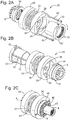
- Figs. 2A-2B show exploded views of the motion converter mechanism 25 with various components separated for ease of viewing.
- Fig. 2A shows the mechanism from a first angle
- Fig. 2B shows the same mechanism from another angle.
- each of the radial projections 34 on the output shaft 6 is elongated, extending along the exterior surface of the output shaft 6 at an angle to the circumferential direction and at an angle to the axis of rotation of the output shaft 6, e.g. in a helical manner.
- the second spring base 28 has complementally recessed channels 36 arranged in its interior surface and configured to receive the protrusions 34.
- the protrusions 34 and channels 36 are configured such that rotation of the second spring base 28 in a first direction relative to the output shaft 6, causes the second spring base 28 to move in a direction towards the first spring base 26.
- each of the radial projections 32 on the second bush 10 is also elongated, extending along the exterior surface of the second bush 10 at an angle to the circumferential direction and at an angle to the axis of rotation of the input shaft 4 (and output shaft 6), e.g. in a helical manner.
- the protrusions 32 on the second bush 10 may be symmetrical relative to the protrusions 34 on the output shaft 6 (about a plane orthogonal to the axis of rotation and arranged between the output shaft 6 and second bush 10).
- the first spring base 26 has complementally recessed channels 38 arranged in its interior surface and configured to receive the protrusions 32.
- the protrusions 32 and channels 38 are configured such that movement of the first spring base 26 along the axis of rotation towards the second bush 10, causes the second bush 10 to be urged in the first rotational direction (shown by the arrow in Fig. 2A ).
- the motion converter mechanism 25 also comprises movement limiting members 40 (not shown in Fig. 1 ) for limiting the distance that the spring bases 26,28 are able to moved away from each other in the longitudinal direction by the spring 30.
- movement limiting members 40 may be configured such that when the torque limiting assembly is assembled, the spring bases 26,28 are maintained at a certain distance apart by the movement limiting members 40 such that the spring 30 is preloaded, i.e. partially compressed, by a preselected amount.
- the movement limiting members 40 may be configured such that the distance, and hence preloading of the spring 30, may be selectively adjusted (e.g. after the torque limiting assembly has been assembled).
- the movement limiting members 40 may be (regulation) bolts that can be screwed, or otherwise selectively moved, relative to the screw bases 26,28 so as to adjust the maximum spacing between the spring bases 26,28 allowed and hence change the level of preloading of the spring 30.
- (regulation) bolts that can be screwed, or otherwise selectively moved, relative to the screw bases 26,28 so as to adjust the maximum spacing between the spring bases 26,28 allowed and hence change the level of preloading of the spring 30.
- Fig. 2C shows the motion converter mechanism 25 when arranged in the torque limiting assembly, albeit with the housing 2 and bearing 5 removed for illustrative purposes only and so that the other components may be viewed more easily.
- Fig. 2D shows a schematic of the assembly when viewed along the direction from the input shaft 4 to the output shaft 6.
- the input shaft 4 comprises a plurality of ramped portions 42 (e.g. forming a cam), in the form of wells, spaced circumferentially around the input shaft 4.
- the first bush 8 comprises a corresponding plurality of apertures 44 therethrough that are arranged at locations radially outward of the curved ramps 42 on the input shaft.
- An engagement member 46 which in this embodiment is in the form of a cylindrical roller member, is located sitting in each of the curved ramps 42 and also within the corresponding aperture 44 in the first bush 8.
- a casing 48 is arranged concentrically around the first bush 8.
- the casing 48 is an independent member from the housing 2 and arranged therein. However, it is contemplated that in other embodiments the casing 48 may be part of the housing 2.
- Fig. 3A shows a longitudinal sectional view of the assembly.
- Fig. 3B shows a view along A-A in Fig. 3A during a normal (low torque) mode of operation and also shows an enlarged view of a portion of that view. It can be seen that there are relatively large gaps 50 (backlashes) between the teeth 52 of the input shaft 4 and the cooperating teeth 56 on the interior side of the first bush 8, and that there are relatively large gaps 58 (backlashes) between the teeth 14 of the exterior side of the first bush 8 and the cooperating teeth 16 on the interior side of the second bush 10.
- Fig. 3C shows a view along B-B in Fig. 3A during a normal (low torque) mode of operation and also shows an enlarged view of a portion of that view.
- Fig. 4A shows a view along A-A in Fig. 3A during a high torque mode of operation
- Fig. 4B shows a view along B-B in Fig. 3A during a high torque mode of operation.
- the input shaft 4 may be rotated about its longitudinal axis in a first direction, as shown by the arrow in Figs. 1 and 3B-3C .
- a normal mode of operation a low torque mode of operation
- Fig. 3B the front sides of the teeth 52 on the external surface of the input shaft 4 push against the rear sides of the teeth 56 on the internal surface of the first bush 8, leaving gaps 50 (backlashes) between the rear sides of the teeth 52 on the input shaft 4 and the front sides of the teeth 56 on the first bush 8.
- the front sides of the teeth 14 on the external surface of the first bush 8 push against the rear sides of the teeth 16 on the internal surface of the second bush 10, leaving gaps 58 (backlashes) between the rear sides of the teeth 14 on the first bush 8 and the front sides of the teeth 16 on the second bush 10.
- the first and second bushes 8,10 are therefore rotated in the first direction by the input shaft 4.
- the rotation of the second bush 10 in the first direction causes the first spring base 26 to also rotate in first direction, since the protrusions 32 on the second bush 10 push on the channels 38 in the first spring base 26.
- the movement limiting members 40 couple the first and second spring bases 26,28 and therefore the second spring base 28 is also driven to rotate in the first direction.
- Rotation of the second spring base 28 causes output shaft 6 to rotate in the first direction, since the channels 36 on the second spring base 28 push on the corresponding protrusions 34 on the output shaft 6.
- the front sides of the teeth 24 on the internal surface of the output shaft 6 push against the rear sides of the teeth 22 on the external surface of the third bush 12, leaving gaps 62 (backlashes) between the rear sides of the teeth 24 on the output shaft and the front sides of the teeth 22 on the third bush 12.
- the front sides of the teeth 20 on the internal surface of the third bush 12 are against the rear sides of the teeth 18 on the external surface of input shaft 4, leaving gaps 60 (backlashes) between the rear sides of the teeth 20 on the third bush and the front sides of the teeth 18 on the third bush 12.
- the second spring base 28 rotates at a higher rate in the first direction than the output shaft 6.
- the angled channels 36 in the second spring base 28 act on the angled protrusions 34 on the output shaft 6.
- the spring 30 between the spring bases 26,28 is compressed, which pushes the first spring base 26 in the longitudinal direction and such that the angled channels 38 in the first spring base 26 move along the second bush 10.
- the angled channels 38 in the first spring base 26 act on the angled protrusions 32 on the second bush 10, thereby driving the second bush 10 to rotate in the first direction.
- the second bush 10 is rotated in the first direction, causing the front sides of the teeth 16 on the internal surface of the second bush 10 to push against the rear sides of the teeth 14 on the external surface of the first bush 8, leaving gaps (backlashes) 57 between the rear sides of the teeth 16 on the internal surface of the second bush 8 and the front sides of the teeth 14 on the external surface of the first bush 8.
- this moves the front sides of the teeth 56 on the internal surface of the first bush 8 to be against the rear sides of the teeth 52 on the external surface of the input shaft 4, leaving gaps 55 (backlashes) between the rear sides of the teeth 56 on the internal surface of the first bush 8 and the front sides of the teeth 52 on the input shaft 4.
- the first and second bushes 8,10 are therefore rotated ahead of the input shaft 4 in the first direction.
- the first and second bushes 8,10 are rotated ahead of the input shaft 4 in the first direction.
- the rollers 46 are located within the apertures 44 of the first bush 8, when the first bush 8 is rotated relative to the input shaft 4, the apertures in the first bush 8 force the rollers 46 up their respective ramps 42 on the input shaft 4 to the position shown in Fig. 5 .
- the rollers 46 are therefore urged radially outwards and into contact with the casing 48.
- the casing 48 may be a static structure.
- the assembly may be configured such that the rollers 46 are urged or moved into engagement with the casing 48 with such force that the friction between the rollers 46 and casing 48 prevents or inhibits rotation of the rollers 46 relative to the casing 48 and hence prevents or inhibits rotation of the input shaft 4. Accordingly, this reduces the torque in the system and may help prevent or reduce damage.
- the assembly is configured to switch from the low torque mode to the high torque mode when a relatively high resistance to rotation of the output shaft 6 causes the spring 30 to be compressed (beyond its initial pre-loaded level).
- the assembly may be configured to switch from the high torque mode to the low torque mode when a relatively low resistance to rotation of the output shaft 6 allows the spring 30 to relax.
- the properties of the spring 30 may define the level of torque in the system at which the assembly switches between the two modes. The level of torque at which such switching occurs is therefore relatively easy to control in the embodiments disclosed herein.
- the movement limiting members 40 may be configured to selectively allow adjustment of the distance between the spring bases 26,28 (prior to use of the assembly) and hence selectively adjust the level of compression (pre-loading) of the spring 30. This defines the level of resistance to compression of the spring 30 and hence the level of torque at which the assembly moves from the low toque mode to the high torque mode.
- the distance between the spring bases 28,30 may be selectively adjusted by known means, such as a threaded bolt 40 that may be screwed relative to the spring bases 26,28 so as to extend or contract the distance therebetween.
- a drive bush is moved rotationally relative to the input shaft in a direction counter to a force of a biasing member (e.g. which may comprise a spring) by a helical engagement between the drive bush and the biasing member, the drive bush being coupled to at least one engagement member (e.g. via an intermediate bush having apertures 44) such that the rotational movement of the drive bush relative to the input shaft causes the at least one engagement member to move relative to the input shaft thereby moving the at least one engagement member into engagement with a casing.
- a biasing member e.g. which may comprise a spring
- engagement members 46 have been described as rollers, they may alternatively be non-rolling engagement members for engaging the casing 48.
- the internal surface of the casing 48 may be configured with barriers that prevent circumferential movement of the engagement members 46 once they have been urged radially outwards.
- protrusions 32,34 have been described as being on the second bush 10 and output shaft 6 and the cooperating channels 36,38 have been described as being on the spring bases 26,28, it is contemplated that the protrusions 32,34 may be on the spring bases 26,28 and the cooperating channels may be on the second bush 10 and output shaft 6.
- protrusions 32,34 may be on an internal surface of the component that it protrudes from and the cooperating channel 36,38 may be on an external surface of the component that it is in.
- the assembly has been described as comprising the first and third bushes 8,12. These bushes allow the backlashes to be easily tailored and for the backlash between two sets of teeth to be relatively small. However, it is contemplated that the first and/or third bush 8,12 may be eliminated. In such embodiments, the teeth 56 on the first end of the input shaft 4 may directly engage the teeth 16 on the "third" bush 12. Alternatively, or additionally, the teeth 18 on the second end of the input shaft 4 may directly engage the teeth 22 on the output shaft 6.
- Embodiments of the present disclosure enable the torque limiting assembly to be relatively small.
- known assemblies comprising torsion bars are required to be relatively large since the torsion bar must be relatively long in order to obtain a suitable torsion angle.
- the torsion bar must also be accurately designed since the torque is dependent on the fourth power of the torsion bar diameter.
Landscapes
- Engineering & Computer Science (AREA)
- General Engineering & Computer Science (AREA)
- Mechanical Engineering (AREA)
- One-Way And Automatic Clutches, And Combinations Of Different Clutches (AREA)
- Transmission Devices (AREA)
Description
- The present disclosure relates generally to assemblies for limiting the amount of torque in a system where an input shaft drives an output shaft.
- Torque limiting apparatus are known in which the input shaft is prevented from rotating if the torque in the system becomes excessive due to mechanical overloading. These apparatus are used to protect mechanical equipment from damage caused by excessive torque.
- A known type of torque limiting apparatus comprises a torsion bar that transmits the turning force (torque) from the input shaft to the output shaft, so that rotation of the input shaft drives a corresponding rotation of the output shaft. If there is excessive resistance to rotation of the output shaft due to mechanical overloading, then the input shaft forces the torsion bar to twist, enabling the input shaft to rotate relative to the output shaft. The torque limiting apparatus is configured such that this relative rotation urges rollers, which are coupled to the input shaft, into contact with a surrounding casing, thereby preventing rotation of the input shaft relative to the casing and hence preventing further torque being applied to the output shaft.
- The present disclosure provides a torque limiting assembly as claimed in claim 1.
- In use, the input shaft is driven to rotate, e.g. by a motor. It will be appreciated that the low torque mode occurs when there is relatively low resistance to rotation of the output shaft and the high torque mode occurs when there is relatively high resistance to rotation of the output shaft.
- The motion conversion mechanism may comprise a rotational-to-linear motion converter and a linear-to-rotational converter.
- The assembly may have the features of
claim 2. - The motion converter mechanism may be moved along the axis of rotation towards the drive bush.
- The first protrusion may be arranged on a circumferential exterior surface of the output shaft. The first channel may be arranged in the circumferential interior surface of the motion converter mechanism. It is alternatively contemplated that the output shaft may comprise the first channel (on an exterior or interior surface) and the motion converter mechanism may comprise the first protrusion (on an interior or exterior surface).
- The assembly may have the features of claim 3.
- The motion converter mechanism may be moved along the axis of rotation and along the drive bush so as to rotate the drive bush.
- The second protrusion may be arranged on a circumferential exterior surface of the drive bush. The second channel may be arranged in the circumferential interior surface of the motion converter mechanism. It is alternatively contemplated that the drive bush may comprise the second channel (on an exterior or interior surface) and the motion converter mechanism may comprise the second protrusion (on an interior or exterior surface).
- The assembly may have the features of
claim 4. - The first protrusion may form part of a helix around the output shaft and/or the first channel may form part of a helix around the motion converter mechanism.
- The second protrusion may form part of a helix around the drive bush and/or the second channel may form part of a helix around the motion converter mechanism.
- The first and second protrusions may form parts of helices that are helical in opposite directions around an axis; and/or the first and second channels may form parts of helices that are helical in opposite directions around an axis.
- The assembly may have the features of
claim 5. - In the low torque mode the engagement between the drive bush and the motion converter mechanism is configured to transform the rotational force from the drive bush into an axial force towards the output shaft, and the engagement between the motion converter mechanism and the output shaft is configured to transform the axial force to a rotational force to rotate the output shaft.
- In the high torque mode the engagement between the output shaft and the motion converter mechanism is configured to transform the relative rotation therebetween into an axial force towards the drive bush, and the engagement between the motion converter mechanism and the drive bush is configured to transform this axial force to a rotational force to rotate the drive bush relative to the input shaft.
- The assembly may have the features of
claim 6. - In the low torque mode there may be no rotation of the motion converter mechanism relative to the output shaft and/or substantially no compression of the resilient biasing member.
- In the low torque mode, the engagement member is not moved or urged to engage the casing and does not prevent or significantly inhibit rotation of the input shaft relative to the casing.
- The assembly may have the features of claim 7.
- This allows the resilient biasing member to be preloaded so that it has a preselected resistance to compression and hence a preselected level of torque at which the assembly switches from the low torque mode to the high torque mode.
- The assembly may have the features of
claim 8. - This allows the torque level at which the assembly switches from the low torque mode to the high torque mode to be adjusted.
- The assembly may have the features of
claim 9. - However, it is contemplated that other forms of resilient biasing member may be used, such as materials that themselves inherently have resilient biasing properties (e.g. elastic properties), rather than being formed into a structure that is resiliently biasing.
- The resilient biasing member may be an annular member arranged around the input shaft.
- The assembly may have the features of
claim 10. - The assembly may have the features of claim 11.
- The provision of the intermediate bush enables the backlashes between each pair of cooperating teeth to be made smaller, whilst still allowing sufficient relative rotation of the components when switching between the low and high torque modes. However, it is contemplated that the intermediate bush may not be provided and that the teeth on the input shaft may directly engage the teeth on the drive bush, with the backlashes being between these sets of teeth.
- In the low torque mode the input shaft may drive the intermediate bush, which may drive the drive bush. In the high torque mode, the drive bush may drive the intermediate bush to rotate relative to the input shaft.
- The assembly may have the features of
claim 12. - The assembly may have the features of claim 13.
- In embodiments comprising the intermediate bush, the intermediate bush may be arranged concentrically with, and between, at least a portion of the input shaft and at least a portion of the casing. The portion of the intermediate bush may comprise an aperture in which the engagement member is arranged, wherein the aperture is sized and configured to contain the engagement so that rotation of the intermediate bush causes a corresponding rotation of the engagement member.
- Although a mechanism of using ramped surfaces has been described for moving or urging the engagement member to engage the casing (so as to prevent or inhibit rotation of the input shaft relative to the casing), it will be appreciated that other mechanisms may be used for converting relative rotational movement into radial movement of the engagement member.
- The torque limiting assembly may have an outer housing and the casing may be part of the housing, or may be a separate member within the housing.
- The assembly may have the features of
claim 14. - Embodiments disclosed herein automatically switch from the low torque mode to the high torque mode when the torque rises to a predetermined level. Optionally, the torque limiting assembly may automatically switch from the high torque mode to the low torque mode when the torque drops to a predetermined level.
- The torque limiting assembly may form part of an actuator, such as an actuator in secondary flight control. The torque limiting assembly may form part of a flight control actuation system in order to prevent overload of the actuation system at the output shaft. For example, the torque limiting assembly may be used in planetary geared actuators in flight control actuation systems. The torque limiting assembly may form part of a high-lift system actuator.
- Various embodiments will now be described, by way of example only, and with reference to the accompanying drawings in which:
-
Fig. 1 shows a perspective sectional view of a torque limiting assembly according to an embodiment of the present disclosure; -
Figs. 2A-2B show exploded views of the motion converter mechanism of the assembly inFig. 1 ,Fig. 2C shows a perspective view of part of the assembly ofFig. 1 , andFig. 2D shows a schematic of the assembly when viewed along the direction from the input shaft to the output shaft in a low torque mode; -
Fig. 3A shows a longitudinal sectional view of the assembly ofFig. 1 ,Fig. 3B shows a view along A-A inFig. 3A during the low torque mode of operation, andFig. 3C shows a view along B-B inFig. 3A during the low torque mode of operation; -
Fig. 4A shows a view along A-A inFig. 3A during a high torque mode of operation, andFig. 4B shows a view along B-B inFig. 3A during a high torque mode of operation; and -
Fig. 5 shows a schematic of the assembly when viewed along the direction from the input shaft to the output shaft in the high torque mode. -
Fig. 1 shows a schematic sectional view of a torque limiting assembly according to an embodiment of the present disclosure. The assembly comprises ahousing 2, aninput shaft 4, abearing 5, anoutput shaft 6, a first bush 8 (an "intermediate bush"), a second bush 10 (a "drive bush"), and athird bush 12. Thefirst bush 8 is arranged concentrically around theinput shaft 4, towards a first end of the input shaft, and thesecond bush 10 is arranged concentrically around thefirst bush 8. The exterior surface of theinput shaft 4 is splined so as to provide teeth (not shown) at the first end that are arranged circumferentially around theinput shaft 4. The interior surface of thefirst bush 8 also comprises teeth (not shown) that engage with the teeth on theinput shaft 4. The exterior surface of thefirst bush 8 comprisesteeth 14 arranged circumferentially around it. The interior surface of thesecond bush 10 also comprisesteeth 16 that engage with theteeth 14 on the exterior surface of thefirst bush 8. - The
third bush 12 is arranged concentrically around theinput shaft 4, towards a second end of theinput shaft 4, and theoutput shaft 6 is arranged concentrically around thethird bush 12. The exterior surface of theinput shaft 4 is splined so as to provideteeth 18 arranged circumferentially around theinput shaft 4. The interior surface of thethird bush 12 also comprisesteeth 20 that engage with theteeth 18 on theinput shaft 4. The exterior surface of thethird bush 12 comprisesteeth 22 arranged circumferentially around it. The interior surface of theoutput shaft 6 also comprisesteeth 24 that engage with theteeth 22 on the exterior surface of thethird bush 12. - The assembly also comprises a
motion converter mechanism 25 for urging thesecond bush 10 circumferentially in the opposite direction to theoutput shaft 6. Thismechanism 25 comprises afirst spring base 26, asecond spring base 28 and aspring 30 arranged between the first and second spring bases for resisting movement of the spring bases 26,28 towards each other and for biasing these bases away from each other in the longitudinal direction of the assembly (i.e. in a direction along the axis of rotation of the input and output shafts). Thefirst spring base 26 is arranged concentrically around thesecond bush 10 and engaged with twoprojections 32 extending radially therefrom. Thesecond spring base 28 is arranged concentrically around theoutput shaft 6 and engaged with twoprojections 34 extending radially therefrom. Thespring base 28 therefore forms a first portion of themotion converter mechanism 25 engaged with theoutput shaft 6, and thespring base 26 forms a second portion of themotion converter mechanism 25 engaged with the output shaft second bush (drive bush) 10. Although each of thesecond bush 10 andoutput shaft 6 are described as having two projections thereon, it is contemplated that only a single projection, or more than two projections, may be provided. Thespring 30 may be a helical spring surrounding around the axes of rotation of the input and output shafts. Alternatively, it is contemplated that a spring (or another type of resilient biasing member) may be arranged between the spring bases 26,28 only at selected circumferential portions of the bases, rather than entirely surrounding the axes of rotation. A plurality of such springs (or other types of resilient biasing members) may be arranged between, and spaced circumferentially around, the spring bases 26,28. -
Figs. 2A-2B show exploded views of themotion converter mechanism 25 with various components separated for ease of viewing.Fig. 2A shows the mechanism from a first angle andFig. 2B shows the same mechanism from another angle. From these Figures it can be seen that each of theradial projections 34 on theoutput shaft 6 is elongated, extending along the exterior surface of theoutput shaft 6 at an angle to the circumferential direction and at an angle to the axis of rotation of theoutput shaft 6, e.g. in a helical manner. FromFig. 2B it can be seen that thesecond spring base 28 has complementally recessedchannels 36 arranged in its interior surface and configured to receive theprotrusions 34. Theprotrusions 34 andchannels 36 are configured such that rotation of thesecond spring base 28 in a first direction relative to theoutput shaft 6, causes thesecond spring base 28 to move in a direction towards thefirst spring base 26. - It can also be seen that each of the
radial projections 32 on thesecond bush 10 is also elongated, extending along the exterior surface of thesecond bush 10 at an angle to the circumferential direction and at an angle to the axis of rotation of the input shaft 4 (and output shaft 6), e.g. in a helical manner. Theprotrusions 32 on thesecond bush 10 may be symmetrical relative to theprotrusions 34 on the output shaft 6 (about a plane orthogonal to the axis of rotation and arranged between theoutput shaft 6 and second bush 10). FromFig. 2A it can be seen that thefirst spring base 26 has complementally recessedchannels 38 arranged in its interior surface and configured to receive theprotrusions 32. Theprotrusions 32 andchannels 38 are configured such that movement of thefirst spring base 26 along the axis of rotation towards thesecond bush 10, causes thesecond bush 10 to be urged in the first rotational direction (shown by the arrow inFig. 2A ). - The
motion converter mechanism 25 also comprises movement limiting members 40 (not shown inFig. 1 ) for limiting the distance that the spring bases 26,28 are able to moved away from each other in the longitudinal direction by thespring 30. Thesemovement limiting members 40 may be configured such that when the torque limiting assembly is assembled, the spring bases 26,28 are maintained at a certain distance apart by themovement limiting members 40 such that thespring 30 is preloaded, i.e. partially compressed, by a preselected amount. Themovement limiting members 40 may be configured such that the distance, and hence preloading of thespring 30, may be selectively adjusted (e.g. after the torque limiting assembly has been assembled). For example, themovement limiting members 40 may be (regulation) bolts that can be screwed, or otherwise selectively moved, relative to the screw bases 26,28 so as to adjust the maximum spacing between the spring bases 26,28 allowed and hence change the level of preloading of thespring 30. -
Fig. 2C shows themotion converter mechanism 25 when arranged in the torque limiting assembly, albeit with thehousing 2 andbearing 5 removed for illustrative purposes only and so that the other components may be viewed more easily. -
Fig. 2D shows a schematic of the assembly when viewed along the direction from theinput shaft 4 to theoutput shaft 6. As can be seen fromFigs. 2C and2D , theinput shaft 4 comprises a plurality of ramped portions 42 (e.g. forming a cam), in the form of wells, spaced circumferentially around theinput shaft 4. Thefirst bush 8 comprises a corresponding plurality ofapertures 44 therethrough that are arranged at locations radially outward of thecurved ramps 42 on the input shaft. Anengagement member 46, which in this embodiment is in the form of a cylindrical roller member, is located sitting in each of thecurved ramps 42 and also within the correspondingaperture 44 in thefirst bush 8. Acasing 48 is arranged concentrically around thefirst bush 8. In the illustrated embodiment, thecasing 48 is an independent member from thehousing 2 and arranged therein. However, it is contemplated that in other embodiments thecasing 48 may be part of thehousing 2. -
Fig. 3A shows a longitudinal sectional view of the assembly.Fig. 3B shows a view along A-A inFig. 3A during a normal (low torque) mode of operation and also shows an enlarged view of a portion of that view. It can be seen that there are relatively large gaps 50 (backlashes) between theteeth 52 of theinput shaft 4 and the cooperatingteeth 56 on the interior side of thefirst bush 8, and that there are relatively large gaps 58 (backlashes) between theteeth 14 of the exterior side of thefirst bush 8 and the cooperatingteeth 16 on the interior side of thesecond bush 10.Fig. 3C shows a view along B-B inFig. 3A during a normal (low torque) mode of operation and also shows an enlarged view of a portion of that view. It can be seen that there are relatively large gaps 60 (backlashes) between theteeth 18 of theinput shaft 4 and theteeth 20 on the interior side of thethird bush 12, and that there are relatively large gaps 62 (backlashes) between theteeth 22 of the exterior side of thethird bush 20 and theteeth 24 on the interior side of theoutput shaft 6. -
Fig. 4A shows a view along A-A inFig. 3A during a high torque mode of operation, andFig. 4B shows a view along B-B inFig. 3A during a high torque mode of operation. - The operation of the torque limiting assembly will now be described. The
input shaft 4 may be rotated about its longitudinal axis in a first direction, as shown by the arrow inFigs. 1 and3B-3C . In a normal mode of operation (a low torque mode of operation) there is relatively little resistance to rotation of theoutput shaft 6 in the first direction. As shown inFig. 3B , the front sides of theteeth 52 on the external surface of theinput shaft 4 push against the rear sides of theteeth 56 on the internal surface of thefirst bush 8, leaving gaps 50 (backlashes) between the rear sides of theteeth 52 on theinput shaft 4 and the front sides of theteeth 56 on thefirst bush 8. In turn, the front sides of theteeth 14 on the external surface of thefirst bush 8 push against the rear sides of theteeth 16 on the internal surface of thesecond bush 10, leaving gaps 58 (backlashes) between the rear sides of theteeth 14 on thefirst bush 8 and the front sides of theteeth 16 on thesecond bush 10. The first andsecond bushes input shaft 4. - Referring to
Fig. 2A , the rotation of thesecond bush 10 in the first direction causes thefirst spring base 26 to also rotate in first direction, since theprotrusions 32 on thesecond bush 10 push on thechannels 38 in thefirst spring base 26. Themovement limiting members 40 couple the first and second spring bases 26,28 and therefore thesecond spring base 28 is also driven to rotate in the first direction. Rotation of thesecond spring base 28 causesoutput shaft 6 to rotate in the first direction, since thechannels 36 on thesecond spring base 28 push on the correspondingprotrusions 34 on theoutput shaft 6. - Referring to
Fig. 3C , the front sides of theteeth 24 on the internal surface of theoutput shaft 6 push against the rear sides of theteeth 22 on the external surface of thethird bush 12, leaving gaps 62 (backlashes) between the rear sides of theteeth 24 on the output shaft and the front sides of theteeth 22 on thethird bush 12. In turn, the front sides of theteeth 20 on the internal surface of thethird bush 12 are against the rear sides of theteeth 18 on the external surface ofinput shaft 4, leaving gaps 60 (backlashes) between the rear sides of theteeth 20 on the third bush and the front sides of theteeth 18 on thethird bush 12. - The operation described so far has been in the normal mode of operation, i.e. a low torque mode, when there is relatively little resistance to rotation of the
output shaft 6 in the first direction. However, when the resistance to rotation in the first direction of theoutput shaft 6 increases to a relatively high level, the assembly switches to a high torque mode of operation as will now be described. - Referring to
Fig. 2A , when the resistance to rotation of theoutput shaft 6 in the first direction increases, thesecond spring base 28 rotates at a higher rate in the first direction than theoutput shaft 6. As thesecond spring base 28 rotates relative to theoutput shaft 6, theangled channels 36 in thesecond spring base 28 act on the angledprotrusions 34 on theoutput shaft 6. This drives thesecond spring base 28 in the longitudinal direction, along the rotational axis, towards thefirst spring base 26. Thespring 30 between the spring bases 26,28 is compressed, which pushes thefirst spring base 26 in the longitudinal direction and such that theangled channels 38 in thefirst spring base 26 move along thesecond bush 10. Theangled channels 38 in thefirst spring base 26 act on the angledprotrusions 32 on thesecond bush 10, thereby driving thesecond bush 10 to rotate in the first direction. - Referring to
Fig. 4A , thesecond bush 10 is rotated in the first direction, causing the front sides of theteeth 16 on the internal surface of thesecond bush 10 to push against the rear sides of theteeth 14 on the external surface of thefirst bush 8, leaving gaps (backlashes) 57 between the rear sides of theteeth 16 on the internal surface of thesecond bush 8 and the front sides of theteeth 14 on the external surface of thefirst bush 8. In turn, this moves the front sides of theteeth 56 on the internal surface of thefirst bush 8 to be against the rear sides of theteeth 52 on the external surface of theinput shaft 4, leaving gaps 55 (backlashes) between the rear sides of theteeth 56 on the internal surface of thefirst bush 8 and the front sides of theteeth 52 on theinput shaft 4. The first andsecond bushes input shaft 4 in the first direction. - As shown in
Fig. 4B , resistance to rotation of theoutput shaft 6 in the first direction results in the front sides of theteeth 22 on the external surface of thethird bush 12 moving to positions against the rear sides of theteeth 24 on theoutput shaft 6. Also, the front sides of theteeth 18 on theinput shaft 4 move to positions against the rear sides of theteeth 20 on the internal surface of thethird bush 12. - As described in relation to
Fig. 4A , in the high torque mode, the first andsecond bushes input shaft 4 in the first direction. As can be seen fromFig. 2C and2D , as therollers 46 are located within theapertures 44 of thefirst bush 8, when thefirst bush 8 is rotated relative to theinput shaft 4, the apertures in thefirst bush 8 force therollers 46 up theirrespective ramps 42 on theinput shaft 4 to the position shown inFig. 5 . Therollers 46 are therefore urged radially outwards and into contact with thecasing 48. Thecasing 48 may be a static structure. The assembly may be configured such that therollers 46 are urged or moved into engagement with thecasing 48 with such force that the friction between therollers 46 andcasing 48 prevents or inhibits rotation of therollers 46 relative to thecasing 48 and hence prevents or inhibits rotation of theinput shaft 4. Accordingly, this reduces the torque in the system and may help prevent or reduce damage. - When the resistance to rotation of the
output shaft 6 in the first direction reduces back down to a normal or acceptable level (i.e. when the torque is reduced to a normal or acceptable level), the force on thespring 30 is relieved and thespring 30 is able to expand, forcing thesecond spring base 26 in the longitudinal direction towards theoutput shaft 6. Thespring 30 therefore exerts a lower force on thefirst spring base 26 in a direction towards thesecond bush 10. Thesecond bush 10 is therefore no longer biased ahead of theinput shaft 4 in the first direction and so theinput shaft 4,first bush 8 andsecond bush 10 are able to rotate back to the relative positions shown inFig. 3B . Thefirst bush 8 therefore rotates relative to theinput shaft 4 back to the position shown inFig. 2D , forcing therollers 46 back down theramp 42 so that they are no longer urged into thecasing 48. Therollers 46 are therefore able to rotate about their axes and do not create significant friction with thecasing 48. Theinput shaft 4 then returns to rotating as normal and theinput shaft 4,third bush 12 andoutput shaft 6 are able to rotate back to the relative positions shown inFig. 3C . - As described above, the assembly is configured to switch from the low torque mode to the high torque mode when a relatively high resistance to rotation of the
output shaft 6 causes thespring 30 to be compressed (beyond its initial pre-loaded level). Similarly, the assembly may be configured to switch from the high torque mode to the low torque mode when a relatively low resistance to rotation of theoutput shaft 6 allows thespring 30 to relax. As such, the properties of thespring 30 may define the level of torque in the system at which the assembly switches between the two modes. The level of torque at which such switching occurs is therefore relatively easy to control in the embodiments disclosed herein. For example, themovement limiting members 40 may be configured to selectively allow adjustment of the distance between the spring bases 26,28 (prior to use of the assembly) and hence selectively adjust the level of compression (pre-loading) of thespring 30. This defines the level of resistance to compression of thespring 30 and hence the level of torque at which the assembly moves from the low toque mode to the high torque mode. The distance between the spring bases 28,30 may be selectively adjusted by known means, such as a threadedbolt 40 that may be screwed relative to the spring bases 26,28 so as to extend or contract the distance therebetween. - According to embodiments of the present disclosure, as torque transmission between an input shaft and an output shaft increases a drive bush is moved rotationally relative to the input shaft in a direction counter to a force of a biasing member (e.g. which may comprise a spring) by a helical engagement between the drive bush and the biasing member, the drive bush being coupled to at least one engagement member (e.g. via an intermediate bush having apertures 44) such that the rotational movement of the drive bush relative to the input shaft causes the at least one engagement member to move relative to the input shaft thereby moving the at least one engagement member into engagement with a casing.
- Although the present disclosure has been described with reference to various embodiments, it will be understood by those skilled in the art that various changes in form and detail may be made without departing from the scope of the invention as set forth in the accompanying claims.
- For example, although the
engagement members 46 have been described as rollers, they may alternatively be non-rolling engagement members for engaging thecasing 48. Alternatively, or additionally, rather than theengagement members 46 frictionally engaging the internal surface of thecasing 48, the internal surface of thecasing 48 may be configured with barriers that prevent circumferential movement of theengagement members 46 once they have been urged radially outwards. - Although the
protrusions second bush 10 andoutput shaft 6 and the cooperatingchannels protrusions second bush 10 andoutput shaft 6. - It is contemplated that the
protrusions channel - The assembly has been described as comprising the first and
third bushes third bush teeth 56 on the first end of theinput shaft 4 may directly engage theteeth 16 on the "third"bush 12. Alternatively, or additionally, theteeth 18 on the second end of theinput shaft 4 may directly engage theteeth 22 on theoutput shaft 6. - Embodiments of the present disclosure enable the torque limiting assembly to be relatively small. For example, known assemblies comprising torsion bars are required to be relatively large since the torsion bar must be relatively long in order to obtain a suitable torsion angle. The torsion bar must also be accurately designed since the torque is dependent on the fourth power of the torsion bar diameter.
Claims (14)
- A torque limiting assembly comprising:an input shaft; an output shaft; a drive bush; a motion converter mechanism; a casing; and at least one engagement member for engaging the casing;wherein the input shaft is coupled to the drive bush, and the drive bush is coupled to the output shaft by the motion converter mechanism such that, in a low torque mode, rotation of the input shaft drives rotation of the drive bush, motion converter mechanism and output shaft; andwherein the output shaft and the motion converter mechanism are coupled such that, in a high torque mode, rotation of the motion converter mechanism relative to the output shaft about an axis of rotation urges the motion converter mechanism in a direction along the axis of rotation, wherein the motion converter mechanism and drive bush are coupled such that when the motion converter mechanism is urged along said axis of rotation the motion converter mechanism rotates the drive bush relative to the input shaft; and wherein the engagement member is coupled to both the drive bush and the input shaft such that when the drive bush is rotated relative to the input shaft, the engagement member is moved or urged to engage the casing so as to prevent or inhibit rotation of the input shaft relative to the casing.
- The assembly of claim 1, wherein one of the output shaft and the motion converter mechanism comprises a first protrusion and the other of the output shaft and motion converter mechanism comprises a first channel in which the protrusion is located, and wherein the first protrusion and first channel are arranged and configured such that, in the high torque mode, said rotation of the motion converter mechanism relative to the output shaft urges the motion converter mechanism in a direction along the axis of rotation.
- The assembly of claim 1 or 2, wherein one of the drive bush and the motion converter mechanism comprises a second protrusion and the other of the drive bush and the motion converter mechanism comprises a second channel in which the second protrusion is located, and wherein the second protrusion and second channel are arranged and configured such that, in the high torque mode, when the motion converter mechanism is urged in a direction along said axis of rotation the motion converter mechanism rotates the drive bush relative to the input shaft.
- The assembly of claim 2 or 3, wherein the first channel and/or first protrusion is elongated and extends both around and along the axis of rotation; and/or
wherein the second channel and/or second protrusion is elongated and extends both around and along the axis of rotation. - The assembly of any preceding claim, wherein motion converter mechanism comprises a first portion engaged with the output shaft, a second portion engaged with the drive bush, and a resilient biasing member arranged between the first and second portions for resisting movement of the first and second portions towards each other along the axis of rotation, and thereby resisting rotation of the motion converter mechanism relative to the output shaft.
- The assembly of claim 5, wherein the resilient biasing member is configured such that in the low torque mode it is compressed by a relatively low amount such that there is a relatively low amount of rotation of the motion converter mechanism relative to the output shaft; and the resilient biasing member is configured such that in the high torque mode it is compressed by a relatively high amount such that there is a relatively high amount of rotation of the motion converter mechanism relative to the output shaft.
- The assembly of claim 5 or 6, wherein the resilient biasing member is arranged between the first and second portions for biasing the first and second portions away from each other along the axis of rotation, and wherein the assembly further comprises a movement limiting member for limiting the maximum amount of movement of the first and second portions away from each other.
- The assembly of claim 7, wherein the movement limiting member is selectively adjustable for selectively adjusting the maximum amount of movement of the first and second portions away from each other.
- The assembly of any one of claims 5-8, wherein the resilient biasing member is a spring.
- The assembly of any preceding claim, wherein the input shaft is coupled to the drive bush by an intermediate bush, wherein the input shaft comprises first teeth engaged with second teeth on the intermediate bush and the intermediate bush comprises third teeth engaged with fourth teeth on the drive bush.
- The assembly of claim 10, wherein backlashes are arranged between the first and second teeth and/or between the third and fourth teeth, thereby allowing the input shaft to drive the drive bush in the low torque mode and allowing rotation of the drive bush relative to the input shaft in the high torque mode.
- The assembly of claim 10 or 11, wherein the intermediate bush contacts the engagement member so that rotation of the intermediate bush causes a corresponding rotation of the engagement member.
- The assembly of any preceding claim, wherein the input shaft comprises a portion in contact with the engagement member that is curved or otherwise ramped in a circumferential direction; and wherein the assembly is configured such that rotation of the drive bush relative to the input shaft, in the high torque mode, forces said engagement member along the curved or ramped surface and moves or urges the engagement member radially outwards to engage the casing so as to prevent or inhibit rotation of the input shaft relative to the casing.
- The assembly of any preceding claim, wherein the engagement member is a roller.
Priority Applications (4)
| Application Number | Priority Date | Filing Date | Title |
|---|---|---|---|
| EP17461567.4A EP3428469B1 (en) | 2017-07-13 | 2017-07-13 | Torque limiter assembly |
| CA3006250A CA3006250A1 (en) | 2017-07-13 | 2018-05-25 | Torque limiter assembly |
| BR102018013474-4A BR102018013474B1 (en) | 2017-07-13 | 2018-06-29 | TORQUE LIMITER ASSEMBLY |
| US16/029,735 US10738837B2 (en) | 2017-07-13 | 2018-07-09 | Torque limiter assembly |
Applications Claiming Priority (1)
| Application Number | Priority Date | Filing Date | Title |
|---|---|---|---|
| EP17461567.4A EP3428469B1 (en) | 2017-07-13 | 2017-07-13 | Torque limiter assembly |
Publications (2)
| Publication Number | Publication Date |
|---|---|
| EP3428469A1 true EP3428469A1 (en) | 2019-01-16 |
| EP3428469B1 EP3428469B1 (en) | 2022-05-18 |
Family
ID=59366359
Family Applications (1)
| Application Number | Title | Priority Date | Filing Date |
|---|---|---|---|
| EP17461567.4A Active EP3428469B1 (en) | 2017-07-13 | 2017-07-13 | Torque limiter assembly |
Country Status (4)
| Country | Link |
|---|---|
| US (1) | US10738837B2 (en) |
| EP (1) | EP3428469B1 (en) |
| BR (1) | BR102018013474B1 (en) |
| CA (1) | CA3006250A1 (en) |
Families Citing this family (2)
| Publication number | Priority date | Publication date | Assignee | Title |
|---|---|---|---|---|
| JP2020159478A (en) * | 2019-03-27 | 2020-10-01 | 日本電産株式会社 | Torque limiter, geared motor, drive mechanism and robot |
| EP3767120B1 (en) * | 2019-07-19 | 2023-05-03 | Goodrich Actuation Systems Limited | Torque limiting device |
Citations (4)
| Publication number | Priority date | Publication date | Assignee | Title |
|---|---|---|---|---|
| US3205985A (en) * | 1963-03-18 | 1965-09-14 | Gardner Denver Co | Torque responsive clutch |
| GB1208958A (en) * | 1967-04-19 | 1970-10-14 | Marcel Pierre Alexis Bouhot | A device for limiting a torque to a predetermined maximum value |
| US3640092A (en) * | 1970-07-10 | 1972-02-08 | Hobson Ltd H M | Torque limiter |
| GB1333153A (en) * | 1967-04-19 | 1973-10-10 | Bouhot M P A | Torque limiting device |
Family Cites Families (9)
| Publication number | Priority date | Publication date | Assignee | Title |
|---|---|---|---|---|
| US1333153A (en) * | 1919-05-16 | 1920-03-09 | Arthur W Bowser | Washing-machine |
| DE2351240C3 (en) * | 1973-10-12 | 1981-06-19 | Robert Bosch Gmbh, 7000 Stuttgart | Overload clutch |
| CH674061A5 (en) * | 1987-04-02 | 1990-04-30 | Elpatronic Ag | |
| DE4426305C2 (en) * | 1994-07-25 | 1997-03-06 | Hilti Ag | Adaptive slip clutch |
| US5901817A (en) | 1997-04-18 | 1999-05-11 | The Boeing Company | Torque limiter with trip indicator |
| DE19953484C2 (en) * | 1999-11-06 | 2002-03-07 | Oechsler Ag | Disengageable swivel drive |
| WO2010147908A2 (en) * | 2009-06-15 | 2010-12-23 | Neapco Llc | Torque limiting driveline |
| CA2802114A1 (en) | 2010-06-25 | 2011-12-29 | Litens Automotive Partnership | Overrunning decoupler |
| US8967004B2 (en) | 2012-06-11 | 2015-03-03 | Remy Technologies Llc | Armature with torque limiter for engine starter |
-
2017
- 2017-07-13 EP EP17461567.4A patent/EP3428469B1/en active Active
-
2018
- 2018-05-25 CA CA3006250A patent/CA3006250A1/en active Pending
- 2018-06-29 BR BR102018013474-4A patent/BR102018013474B1/en active IP Right Grant
- 2018-07-09 US US16/029,735 patent/US10738837B2/en active Active
Patent Citations (4)
| Publication number | Priority date | Publication date | Assignee | Title |
|---|---|---|---|---|
| US3205985A (en) * | 1963-03-18 | 1965-09-14 | Gardner Denver Co | Torque responsive clutch |
| GB1208958A (en) * | 1967-04-19 | 1970-10-14 | Marcel Pierre Alexis Bouhot | A device for limiting a torque to a predetermined maximum value |
| GB1333153A (en) * | 1967-04-19 | 1973-10-10 | Bouhot M P A | Torque limiting device |
| US3640092A (en) * | 1970-07-10 | 1972-02-08 | Hobson Ltd H M | Torque limiter |
Also Published As
| Publication number | Publication date |
|---|---|
| BR102018013474A2 (en) | 2019-06-11 |
| CA3006250A1 (en) | 2019-01-13 |
| BR102018013474B1 (en) | 2023-03-28 |
| EP3428469B1 (en) | 2022-05-18 |
| US10738837B2 (en) | 2020-08-11 |
| US20190017553A1 (en) | 2019-01-17 |
Similar Documents
| Publication | Publication Date | Title |
|---|---|---|
| US6202803B1 (en) | Output load limiter | |
| CN107131340B (en) | Adjusting device and valve control device having an adjusting device | |
| US5605071A (en) | Enveloped worm gear clutch wedgelock responsive to reaction force | |
| DE69826560T2 (en) | Torque limiter with trip status indicator | |
| KR101855712B1 (en) | Backlash-free cycloidal reducer | |
| EP2745988B1 (en) | Hand-Held Power Tool with Torque Limiting Unit | |
| KR20140073442A (en) | Clutch actuated by inertia mass and friction damping | |
| WO2008053226A1 (en) | Worm gear for electric assisted steering apparatus and method of controlling the movement of the worm shaft in a worm gearing | |
| US10738837B2 (en) | Torque limiter assembly | |
| CN113767229A (en) | Reverse input disconnect clutch | |
| CN103206462B (en) | Bearing pre-tightening device | |
| JP7113600B2 (en) | Rotary drive with load-dependent brake | |
| EP0878724B1 (en) | Electrically driven optical element with manual operation member | |
| US20180104801A1 (en) | Torque-limiting driver with embodied roller | |
| EP3743635B1 (en) | Anti-backdrive lock | |
| DE102015102543B3 (en) | Device for phase shifting the angle of rotation of a drive part to a driven part | |
| US11440181B2 (en) | Planetary gear train, gearbox and industrial robot | |
| CN110131328A (en) | Multimode clutch | |
| EP3611374A1 (en) | Rotary actuator | |
| EP3862588A1 (en) | Adjustable spring assembly | |
| WO2007036385A1 (en) | Axial backlash-adjusted transmission drive unit | |
| JP2020143709A (en) | Linear motion actuator | |
| EP1645780A2 (en) | Screw Actuator | |
| JP2018179109A (en) | Torque limiter | |
| EP3699448A1 (en) | Regulating device for torque limiter |
Legal Events
| Date | Code | Title | Description |
|---|---|---|---|
| PUAI | Public reference made under article 153(3) epc to a published international application that has entered the european phase |
Free format text: ORIGINAL CODE: 0009012 |
|
| STAA | Information on the status of an ep patent application or granted ep patent |
Free format text: STATUS: THE APPLICATION HAS BEEN PUBLISHED |
|
| AK | Designated contracting states |
Kind code of ref document: A1 Designated state(s): AL AT BE BG CH CY CZ DE DK EE ES FI FR GB GR HR HU IE IS IT LI LT LU LV MC MK MT NL NO PL PT RO RS SE SI SK SM TR |
|
| AX | Request for extension of the european patent |
Extension state: BA ME |
|
| STAA | Information on the status of an ep patent application or granted ep patent |
Free format text: STATUS: REQUEST FOR EXAMINATION WAS MADE |
|
| 17P | Request for examination filed |
Effective date: 20190716 |
|
| RBV | Designated contracting states (corrected) |
Designated state(s): AL AT BE BG CH CY CZ DE DK EE ES FI FR GB GR HR HU IE IS IT LI LT LU LV MC MK MT NL NO PL PT RO RS SE SI SK SM TR |
|
| STAA | Information on the status of an ep patent application or granted ep patent |
Free format text: STATUS: EXAMINATION IS IN PROGRESS |
|
| 17Q | First examination report despatched |
Effective date: 20200904 |
|
| GRAP | Despatch of communication of intention to grant a patent |
Free format text: ORIGINAL CODE: EPIDOSNIGR1 |
|
| STAA | Information on the status of an ep patent application or granted ep patent |
Free format text: STATUS: GRANT OF PATENT IS INTENDED |
|
| INTG | Intention to grant announced |
Effective date: 20211207 |
|
| GRAS | Grant fee paid |
Free format text: ORIGINAL CODE: EPIDOSNIGR3 |
|
| GRAA | (expected) grant |
Free format text: ORIGINAL CODE: 0009210 |
|
| STAA | Information on the status of an ep patent application or granted ep patent |
Free format text: STATUS: THE PATENT HAS BEEN GRANTED |
|
| AK | Designated contracting states |
Kind code of ref document: B1 Designated state(s): AL AT BE BG CH CY CZ DE DK EE ES FI FR GB GR HR HU IE IS IT LI LT LU LV MC MK MT NL NO PL PT RO RS SE SI SK SM TR |
|
| REG | Reference to a national code |
Ref country code: GB Ref legal event code: FG4D |
|
| REG | Reference to a national code |
Ref country code: CH Ref legal event code: EP |
|
| REG | Reference to a national code |
Ref country code: IE Ref legal event code: FG4D |
|
| REG | Reference to a national code |
Ref country code: DE Ref legal event code: R096 Ref document number: 602017057582 Country of ref document: DE |
|
| REG | Reference to a national code |
Ref country code: AT Ref legal event code: REF Ref document number: 1493309 Country of ref document: AT Kind code of ref document: T Effective date: 20220615 |
|
| REG | Reference to a national code |
Ref country code: LT Ref legal event code: MG9D |
|
| REG | Reference to a national code |
Ref country code: NL Ref legal event code: MP Effective date: 20220518 |
|
| REG | Reference to a national code |
Ref country code: AT Ref legal event code: MK05 Ref document number: 1493309 Country of ref document: AT Kind code of ref document: T Effective date: 20220518 |
|
| PG25 | Lapsed in a contracting state [announced via postgrant information from national office to epo] |
Ref country code: SE Free format text: LAPSE BECAUSE OF FAILURE TO SUBMIT A TRANSLATION OF THE DESCRIPTION OR TO PAY THE FEE WITHIN THE PRESCRIBED TIME-LIMIT Effective date: 20220518 Ref country code: PT Free format text: LAPSE BECAUSE OF FAILURE TO SUBMIT A TRANSLATION OF THE DESCRIPTION OR TO PAY THE FEE WITHIN THE PRESCRIBED TIME-LIMIT Effective date: 20220919 Ref country code: NO Free format text: LAPSE BECAUSE OF FAILURE TO SUBMIT A TRANSLATION OF THE DESCRIPTION OR TO PAY THE FEE WITHIN THE PRESCRIBED TIME-LIMIT Effective date: 20220818 Ref country code: NL Free format text: LAPSE BECAUSE OF FAILURE TO SUBMIT A TRANSLATION OF THE DESCRIPTION OR TO PAY THE FEE WITHIN THE PRESCRIBED TIME-LIMIT Effective date: 20220518 Ref country code: LT Free format text: LAPSE BECAUSE OF FAILURE TO SUBMIT A TRANSLATION OF THE DESCRIPTION OR TO PAY THE FEE WITHIN THE PRESCRIBED TIME-LIMIT Effective date: 20220518 Ref country code: HR Free format text: LAPSE BECAUSE OF FAILURE TO SUBMIT A TRANSLATION OF THE DESCRIPTION OR TO PAY THE FEE WITHIN THE PRESCRIBED TIME-LIMIT Effective date: 20220518 Ref country code: GR Free format text: LAPSE BECAUSE OF FAILURE TO SUBMIT A TRANSLATION OF THE DESCRIPTION OR TO PAY THE FEE WITHIN THE PRESCRIBED TIME-LIMIT Effective date: 20220819 Ref country code: FI Free format text: LAPSE BECAUSE OF FAILURE TO SUBMIT A TRANSLATION OF THE DESCRIPTION OR TO PAY THE FEE WITHIN THE PRESCRIBED TIME-LIMIT Effective date: 20220518 Ref country code: ES Free format text: LAPSE BECAUSE OF FAILURE TO SUBMIT A TRANSLATION OF THE DESCRIPTION OR TO PAY THE FEE WITHIN THE PRESCRIBED TIME-LIMIT Effective date: 20220518 Ref country code: BG Free format text: LAPSE BECAUSE OF FAILURE TO SUBMIT A TRANSLATION OF THE DESCRIPTION OR TO PAY THE FEE WITHIN THE PRESCRIBED TIME-LIMIT Effective date: 20220818 Ref country code: AT Free format text: LAPSE BECAUSE OF FAILURE TO SUBMIT A TRANSLATION OF THE DESCRIPTION OR TO PAY THE FEE WITHIN THE PRESCRIBED TIME-LIMIT Effective date: 20220518 |
|
| PG25 | Lapsed in a contracting state [announced via postgrant information from national office to epo] |
Ref country code: RS Free format text: LAPSE BECAUSE OF FAILURE TO SUBMIT A TRANSLATION OF THE DESCRIPTION OR TO PAY THE FEE WITHIN THE PRESCRIBED TIME-LIMIT Effective date: 20220518 Ref country code: PL Free format text: LAPSE BECAUSE OF FAILURE TO SUBMIT A TRANSLATION OF THE DESCRIPTION OR TO PAY THE FEE WITHIN THE PRESCRIBED TIME-LIMIT Effective date: 20220518 Ref country code: LV Free format text: LAPSE BECAUSE OF FAILURE TO SUBMIT A TRANSLATION OF THE DESCRIPTION OR TO PAY THE FEE WITHIN THE PRESCRIBED TIME-LIMIT Effective date: 20220518 Ref country code: IS Free format text: LAPSE BECAUSE OF FAILURE TO SUBMIT A TRANSLATION OF THE DESCRIPTION OR TO PAY THE FEE WITHIN THE PRESCRIBED TIME-LIMIT Effective date: 20220918 |
|
| PG25 | Lapsed in a contracting state [announced via postgrant information from national office to epo] |
Ref country code: SM Free format text: LAPSE BECAUSE OF FAILURE TO SUBMIT A TRANSLATION OF THE DESCRIPTION OR TO PAY THE FEE WITHIN THE PRESCRIBED TIME-LIMIT Effective date: 20220518 Ref country code: SK Free format text: LAPSE BECAUSE OF FAILURE TO SUBMIT A TRANSLATION OF THE DESCRIPTION OR TO PAY THE FEE WITHIN THE PRESCRIBED TIME-LIMIT Effective date: 20220518 Ref country code: RO Free format text: LAPSE BECAUSE OF FAILURE TO SUBMIT A TRANSLATION OF THE DESCRIPTION OR TO PAY THE FEE WITHIN THE PRESCRIBED TIME-LIMIT Effective date: 20220518 Ref country code: EE Free format text: LAPSE BECAUSE OF FAILURE TO SUBMIT A TRANSLATION OF THE DESCRIPTION OR TO PAY THE FEE WITHIN THE PRESCRIBED TIME-LIMIT Effective date: 20220518 Ref country code: DK Free format text: LAPSE BECAUSE OF FAILURE TO SUBMIT A TRANSLATION OF THE DESCRIPTION OR TO PAY THE FEE WITHIN THE PRESCRIBED TIME-LIMIT Effective date: 20220518 Ref country code: CZ Free format text: LAPSE BECAUSE OF FAILURE TO SUBMIT A TRANSLATION OF THE DESCRIPTION OR TO PAY THE FEE WITHIN THE PRESCRIBED TIME-LIMIT Effective date: 20220518 |
|
| REG | Reference to a national code |
Ref country code: DE Ref legal event code: R097 Ref document number: 602017057582 Country of ref document: DE |
|
| PG25 | Lapsed in a contracting state [announced via postgrant information from national office to epo] |
Ref country code: MC Free format text: LAPSE BECAUSE OF FAILURE TO SUBMIT A TRANSLATION OF THE DESCRIPTION OR TO PAY THE FEE WITHIN THE PRESCRIBED TIME-LIMIT Effective date: 20220518 |
|
| REG | Reference to a national code |
Ref country code: CH Ref legal event code: PL |
|
| PLBE | No opposition filed within time limit |
Free format text: ORIGINAL CODE: 0009261 |
|
| STAA | Information on the status of an ep patent application or granted ep patent |
Free format text: STATUS: NO OPPOSITION FILED WITHIN TIME LIMIT |
|
| REG | Reference to a national code |
Ref country code: BE Ref legal event code: MM Effective date: 20220731 |
|
| PG25 | Lapsed in a contracting state [announced via postgrant information from national office to epo] |
Ref country code: AL Free format text: LAPSE BECAUSE OF FAILURE TO SUBMIT A TRANSLATION OF THE DESCRIPTION OR TO PAY THE FEE WITHIN THE PRESCRIBED TIME-LIMIT Effective date: 20220518 |
|
| 26N | No opposition filed |
Effective date: 20230221 |
|
| PG25 | Lapsed in a contracting state [announced via postgrant information from national office to epo] |
Ref country code: LU Free format text: LAPSE BECAUSE OF NON-PAYMENT OF DUE FEES Effective date: 20220713 Ref country code: LI Free format text: LAPSE BECAUSE OF NON-PAYMENT OF DUE FEES Effective date: 20220731 Ref country code: CH Free format text: LAPSE BECAUSE OF NON-PAYMENT OF DUE FEES Effective date: 20220731 |
|
| PG25 | Lapsed in a contracting state [announced via postgrant information from national office to epo] |
Ref country code: SI Free format text: LAPSE BECAUSE OF FAILURE TO SUBMIT A TRANSLATION OF THE DESCRIPTION OR TO PAY THE FEE WITHIN THE PRESCRIBED TIME-LIMIT Effective date: 20220518 Ref country code: BE Free format text: LAPSE BECAUSE OF NON-PAYMENT OF DUE FEES Effective date: 20220731 |
|
| P01 | Opt-out of the competence of the unified patent court (upc) registered |
Effective date: 20230522 |
|
| PG25 | Lapsed in a contracting state [announced via postgrant information from national office to epo] |
Ref country code: IE Free format text: LAPSE BECAUSE OF NON-PAYMENT OF DUE FEES Effective date: 20220713 |
|
| PG25 | Lapsed in a contracting state [announced via postgrant information from national office to epo] |
Ref country code: HU Free format text: LAPSE BECAUSE OF FAILURE TO SUBMIT A TRANSLATION OF THE DESCRIPTION OR TO PAY THE FEE WITHIN THE PRESCRIBED TIME-LIMIT; INVALID AB INITIO Effective date: 20170713 |
|
| PG25 | Lapsed in a contracting state [announced via postgrant information from national office to epo] |
Ref country code: MK Free format text: LAPSE BECAUSE OF FAILURE TO SUBMIT A TRANSLATION OF THE DESCRIPTION OR TO PAY THE FEE WITHIN THE PRESCRIBED TIME-LIMIT Effective date: 20220511 Ref country code: CY Free format text: LAPSE BECAUSE OF FAILURE TO SUBMIT A TRANSLATION OF THE DESCRIPTION OR TO PAY THE FEE WITHIN THE PRESCRIBED TIME-LIMIT Effective date: 20220511 |
|
| PG25 | Lapsed in a contracting state [announced via postgrant information from national office to epo] |
Ref country code: TR Free format text: LAPSE BECAUSE OF FAILURE TO SUBMIT A TRANSLATION OF THE DESCRIPTION OR TO PAY THE FEE WITHIN THE PRESCRIBED TIME-LIMIT Effective date: 20220511 |
|
| PG25 | Lapsed in a contracting state [announced via postgrant information from national office to epo] |
Ref country code: MT Free format text: LAPSE BECAUSE OF FAILURE TO SUBMIT A TRANSLATION OF THE DESCRIPTION OR TO PAY THE FEE WITHIN THE PRESCRIBED TIME-LIMIT Effective date: 20220511 |
|
| PG25 | Lapsed in a contracting state [announced via postgrant information from national office to epo] |
Ref country code: BG Free format text: LAPSE BECAUSE OF FAILURE TO SUBMIT A TRANSLATION OF THE DESCRIPTION OR TO PAY THE FEE WITHIN THE PRESCRIBED TIME-LIMIT Effective date: 20220518 |
|
| PG25 | Lapsed in a contracting state [announced via postgrant information from national office to epo] |
Ref country code: BG Free format text: LAPSE BECAUSE OF FAILURE TO SUBMIT A TRANSLATION OF THE DESCRIPTION OR TO PAY THE FEE WITHIN THE PRESCRIBED TIME-LIMIT Effective date: 20220518 |
|
| PGFP | Annual fee paid to national office [announced via postgrant information from national office to epo] |
Ref country code: GB Payment date: 20250619 Year of fee payment: 9 |
|
| PGFP | Annual fee paid to national office [announced via postgrant information from national office to epo] |
Ref country code: FR Payment date: 20250620 Year of fee payment: 9 |
|
| PGFP | Annual fee paid to national office [announced via postgrant information from national office to epo] |
Ref country code: DE Payment date: 20250620 Year of fee payment: 9 |
|
| PGFP | Annual fee paid to national office [announced via postgrant information from national office to epo] |
Ref country code: IT Payment date: 20250619 Year of fee payment: 9 |