EP3428433A1 - Internal combustion engine intake structure - Google Patents
Internal combustion engine intake structure Download PDFInfo
- Publication number
- EP3428433A1 EP3428433A1 EP17763122.3A EP17763122A EP3428433A1 EP 3428433 A1 EP3428433 A1 EP 3428433A1 EP 17763122 A EP17763122 A EP 17763122A EP 3428433 A1 EP3428433 A1 EP 3428433A1
- Authority
- EP
- European Patent Office
- Prior art keywords
- inlet pipe
- intake
- cylinder head
- intake port
- partition member
- Prior art date
- Legal status (The legal status is an assumption and is not a legal conclusion. Google has not performed a legal analysis and makes no representation as to the accuracy of the status listed.)
- Granted
Links
Images


Classifications
-
- F—MECHANICAL ENGINEERING; LIGHTING; HEATING; WEAPONS; BLASTING
- F02—COMBUSTION ENGINES; HOT-GAS OR COMBUSTION-PRODUCT ENGINE PLANTS
- F02F—CYLINDERS, PISTONS OR CASINGS, FOR COMBUSTION ENGINES; ARRANGEMENTS OF SEALINGS IN COMBUSTION ENGINES
- F02F1/00—Cylinders; Cylinder heads
- F02F1/24—Cylinder heads
- F02F1/42—Shape or arrangement of intake or exhaust channels in cylinder heads
- F02F1/4235—Shape or arrangement of intake or exhaust channels in cylinder heads of intake channels
- F02F1/4242—Shape or arrangement of intake or exhaust channels in cylinder heads of intake channels with a partition wall inside the channel
-
- F—MECHANICAL ENGINEERING; LIGHTING; HEATING; WEAPONS; BLASTING
- F02—COMBUSTION ENGINES; HOT-GAS OR COMBUSTION-PRODUCT ENGINE PLANTS
- F02B—INTERNAL-COMBUSTION PISTON ENGINES; COMBUSTION ENGINES IN GENERAL
- F02B31/00—Modifying induction systems for imparting a rotation to the charge in the cylinder
- F02B31/04—Modifying induction systems for imparting a rotation to the charge in the cylinder by means within the induction channel, e.g. deflectors
-
- F—MECHANICAL ENGINEERING; LIGHTING; HEATING; WEAPONS; BLASTING
- F02—COMBUSTION ENGINES; HOT-GAS OR COMBUSTION-PRODUCT ENGINE PLANTS
- F02M—SUPPLYING COMBUSTION ENGINES IN GENERAL WITH COMBUSTIBLE MIXTURES OR CONSTITUENTS THEREOF
- F02M35/00—Combustion-air cleaners, air intakes, intake silencers, or induction systems specially adapted for, or arranged on, internal-combustion engines
- F02M35/10—Air intakes; Induction systems
- F02M35/10006—Air intakes; Induction systems characterised by the position of elements of the air intake system in direction of the air intake flow, i.e. between ambient air inlet and supply to the combustion chamber
- F02M35/10072—Intake runners
-
- F—MECHANICAL ENGINEERING; LIGHTING; HEATING; WEAPONS; BLASTING
- F02—COMBUSTION ENGINES; HOT-GAS OR COMBUSTION-PRODUCT ENGINE PLANTS
- F02M—SUPPLYING COMBUSTION ENGINES IN GENERAL WITH COMBUSTIBLE MIXTURES OR CONSTITUENTS THEREOF
- F02M35/00—Combustion-air cleaners, air intakes, intake silencers, or induction systems specially adapted for, or arranged on, internal-combustion engines
- F02M35/10—Air intakes; Induction systems
- F02M35/10006—Air intakes; Induction systems characterised by the position of elements of the air intake system in direction of the air intake flow, i.e. between ambient air inlet and supply to the combustion chamber
- F02M35/10078—Connections of intake systems to the engine
- F02M35/10085—Connections of intake systems to the engine having a connecting piece, e.g. a flange, between the engine and the air intake being foreseen with a throttle valve, fuel injector, mixture ducts or the like
-
- F—MECHANICAL ENGINEERING; LIGHTING; HEATING; WEAPONS; BLASTING
- F02—COMBUSTION ENGINES; HOT-GAS OR COMBUSTION-PRODUCT ENGINE PLANTS
- F02M—SUPPLYING COMBUSTION ENGINES IN GENERAL WITH COMBUSTIBLE MIXTURES OR CONSTITUENTS THEREOF
- F02M35/00—Combustion-air cleaners, air intakes, intake silencers, or induction systems specially adapted for, or arranged on, internal-combustion engines
- F02M35/10—Air intakes; Induction systems
- F02M35/10242—Devices or means connected to or integrated into air intakes; Air intakes combined with other engine or vehicle parts
- F02M35/10262—Flow guides, obstructions, deflectors or the like
-
- F—MECHANICAL ENGINEERING; LIGHTING; HEATING; WEAPONS; BLASTING
- F02—COMBUSTION ENGINES; HOT-GAS OR COMBUSTION-PRODUCT ENGINE PLANTS
- F02M—SUPPLYING COMBUSTION ENGINES IN GENERAL WITH COMBUSTIBLE MIXTURES OR CONSTITUENTS THEREOF
- F02M35/00—Combustion-air cleaners, air intakes, intake silencers, or induction systems specially adapted for, or arranged on, internal-combustion engines
- F02M35/16—Combustion-air cleaners, air intakes, intake silencers, or induction systems specially adapted for, or arranged on, internal-combustion engines characterised by use in vehicles
- F02M35/162—Motorcycles; All-terrain vehicles, e.g. quads, snowmobiles; Small vehicles, e.g. forklifts
-
- F—MECHANICAL ENGINEERING; LIGHTING; HEATING; WEAPONS; BLASTING
- F02—COMBUSTION ENGINES; HOT-GAS OR COMBUSTION-PRODUCT ENGINE PLANTS
- F02M—SUPPLYING COMBUSTION ENGINES IN GENERAL WITH COMBUSTIBLE MIXTURES OR CONSTITUENTS THEREOF
- F02M35/00—Combustion-air cleaners, air intakes, intake silencers, or induction systems specially adapted for, or arranged on, internal-combustion engines
- F02M35/10—Air intakes; Induction systems
- F02M35/1015—Air intakes; Induction systems characterised by the engine type
- F02M35/1017—Small engines, e.g. for handheld tools, or model engines; Single cylinder engines
-
- F—MECHANICAL ENGINEERING; LIGHTING; HEATING; WEAPONS; BLASTING
- F02—COMBUSTION ENGINES; HOT-GAS OR COMBUSTION-PRODUCT ENGINE PLANTS
- F02M—SUPPLYING COMBUSTION ENGINES IN GENERAL WITH COMBUSTIBLE MIXTURES OR CONSTITUENTS THEREOF
- F02M35/00—Combustion-air cleaners, air intakes, intake silencers, or induction systems specially adapted for, or arranged on, internal-combustion engines
- F02M35/10—Air intakes; Induction systems
- F02M35/10242—Devices or means connected to or integrated into air intakes; Air intakes combined with other engine or vehicle parts
- F02M35/10288—Air intakes combined with another engine part, e.g. cylinder head cover or being cast in one piece with the exhaust manifold, cylinder head or engine block
-
- Y—GENERAL TAGGING OF NEW TECHNOLOGICAL DEVELOPMENTS; GENERAL TAGGING OF CROSS-SECTIONAL TECHNOLOGIES SPANNING OVER SEVERAL SECTIONS OF THE IPC; TECHNICAL SUBJECTS COVERED BY FORMER USPC CROSS-REFERENCE ART COLLECTIONS [XRACs] AND DIGESTS
- Y02—TECHNOLOGIES OR APPLICATIONS FOR MITIGATION OR ADAPTATION AGAINST CLIMATE CHANGE
- Y02T—CLIMATE CHANGE MITIGATION TECHNOLOGIES RELATED TO TRANSPORTATION
- Y02T10/00—Road transport of goods or passengers
- Y02T10/10—Internal combustion engine [ICE] based vehicles
- Y02T10/12—Improving ICE efficiencies
Definitions
- the present invention relates to an intake structure for use in an internal combustion engine, in which a partition member is integrally formed with an intake port.
- intake structures for internal combustion engines include a continuous intake air-fuel mixture passage provided by an inlet pipe that is connected to the intake port of a cylinder head.
- One such intake structure disclosed in Patent Document 1 mentioned below, for example, has a partition member provided in an intake air passageway in order to generate a tumbling air-fuel mixture flow in the combustion chamber of an internal combustion engine, the partition member dividing the intake air-fuel mixture passage into a tumble flow passageway and a main flow passageway.
- an intake air-fuel mixture from the on/off valve of a carburetor is led into the tumble flow passageway to promote the generation of a tumble flow.
- an intake air-fuel mixture is led chiefly into the main flow passageway.
- the cylinder head and the inlet pipe may be made of different materials, and the partition member provided in the intake air-fuel mixture passage may include separate partition members provided respectively in the cylinder head and the inlet pipe.
- the partition member provided in the cylinder head and leading to the intake port is often cast integrally with the cylinder head.
- a hollow or vacant area is formed between the partition member and an inlet pipe mount as in the prior art, then the fluidity of a molten metal, typically molten aluminum, that flows to cast the thin partition member tends to be poor.
- the molten aluminum that is about to flow to cast the partition member has its heat absorbed by a mold for forming the hollow or vacant area, so that the molten aluminum tends to solidify before it flows into the partition member.
- JP H11-210478 A ( FIGS. 1 , 6 , and 11)
- the present invention has been made in view of the above prior art. It is an object of the present invention to provide an intake structure for use in an internal combustion engine including a cylinder head in which a partition member is integrally formed with an intake port, wherein the intake structure is arranged to make it easy to retain the heat of a molten metal when the molten metal is introduced to cast the intake structure, thereby increasing the fluidity of the molten metal introduced to cast the intake structure.
- an intake structure for an internal combustion engine in which a combustion chamber is defined between a top surface of a piston slidably fitted in a cylinder bore in a cylinder block and an inner surface of a combustion chamber ceiling wall in a cylinder head which is faced by the top surface, and an intake port and an exhaust port extend from an intake valve opening and an exhaust valve opening that are open in the inner surface of the combustion chamber ceiling wall in the cylinder head, the intake port and the exhaust port being curved in directions spaced away from each other.
- An inlet pipe is connected to the intake port, providing a continuous intake air-fuel mixture passage which is divided into a first intake air-fuel mixture passageway and a second intake air-fuel mixture passageway by a partition, the partition member in the intake port being integrally formed with the cylinder head.
- the cylinder head has a connection face member for connection to the inlet pipe, the connection face member including an inlet pipe mount portion for receiving an inlet pipe fastening member to be threaded therein, and the inlet pipe mount portion and the partition member of the intake port are integrally formed with each other, and at least part of the inlet pipe mount portion is positioned on an extension of the partition member in a direction across the intake port on an upstream end face of the intake port.
- the inlet pipe mount portion and the partition member are integrally coupled to each other by a joint.
- the joint lies on an extension of the partition member extending in leftward and rightward directions across the intake port.
- the cylinder head has a spark ignition plug mount on an outer surface of the combustion chamber ceiling wall, and a cavity in a region of the spark ignition plug mount, the cylinder head having an opening on the side of the inlet pipe mount portion of the cavity, the opening and the inlet pipe mount portion being offset from each other.
- the partition member and the inlet pipe mount portion are brought closely to each other, providing an increased volume in a compact area, so that when the cylinder head is cast, it is easy to retain the heat of a molten metal, and fluidity of the molten metal is increased.
- the partition member and the inlet pipe mount portion are structurally contiguous, the rigidity of and around the inlet pipe mount portion is increased.
- the joint by which the inlet pipe mount portion and the partition member are coupled to each other allows a molten metal introduced to cast the cylinder head to flow therethrough into the partition member. Furthermore, fluidity of a molten metal flowing into the partition is increased because the heat of the molten metal prevented from being absorbed by a mold for forming a hollow area which would otherwise be present between the inlet pipe mount portion and the partition member.
- the open area of the opening of the cavity is increased to cool the spark ignition plug mount of the cylinder head well.
- the vehicle refers to a small-size two-wheel vehicle such as a scooter-type motorcycle, for example.
- FR represents a forward direction of the vehicle, LH a leftward direction of the vehicle, RH a rightward direction of the vehicle, and UP an upward direction of the vehicle.
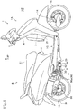
- FIG. 1 shows a right-hand side elevational view of a two-wheel scooter-type motorcycle (hereinafter simply referred to as "motorcycle") 1 having a power unit that includes an internal combustion engine according to the present embodiment.
- motorcycle a two-wheel scooter-type motorcycle
- the motorcycle 1 includes a front vehicle portion 1A and a rear vehicle portion 1B that are coupled to each other by a low floor portion 1C, and has a vehicle body including a vehicle body frame 2 as a skeletal structure that generally includes a down tube 21 and a pair of left and right main pipes 22 (see FIG. 2 ).
- the down tube 21 extends downward from a head pipe 20 of the front vehicle portion 1A and is bent horizontally at a lower end portion thereof and extends rearward below the floor portion 1C.
- a pair of the left and right main pipes 22 are joined to a rear end of the horizontal portion of the down tube 21 by a joint frame 23 extending in widthwise directions of the vehicle.
- the main pipes 22 extend obliquely rearward from the joint frame 23, and are bent at a reduced gradient and extend rearward.
- the main pipes 22 support a rider's seat 11, a storage case, a fuel tank, and the like beneath the rider's seat 11, and an area below the rider's seat 11 is covered with the vehicle body cover 12.
- a handle 13 is angularly movably supported on and disposed above the head pipe 20, and a front fork 14 extends downward from the head pipe 20, with a front wheel 15 rotatably supported on the lower end of the front fork 14.
- FIG. 2 which is a right-hand side elevational view of a rear portion of the motorcycle 1, with the vehicle body cover 12 removed, a bracket 24 projects from the lower ends of the oblique portions of the main pipes 22, and a power unit 3 is swingably joined to and supported on the bracket 24 by a link 25.
- the power unit 3 includes, in its front portion, a single-cylinder four-stroke-cycle air-cooled internal combustion engine (hereinafter referred to as "internal combustion engine") 30.
- the internal combustion engine 30 includes a crankshaft 51 extending in the widthwise directions of the vehicle and rotatably supported in a front portion of a power unit case 50 that serves as a crankcase 50a, and has a cylinder axis X inclined largely forward so as to lie essentially horizontally.
- a hanger arm 52 projects forward from the lower end of the power unit case 50 and has an end coupled to the link 25 that is mounted to the bracket 24 on the main pipes 22.
- the power unit 3 has the internal combustion engine 30 inclined largely forward in the front portion of the power unit case 50 that serves as the crankcase 50a.
- the internal combustion engine 30 includes a cylinder block 31, a cylinder head 32, and a cylinder head cover 33 that are successively stacked and fastened together.
- a power transmitting case 55 including a belt-type continuously variable transmission and the like, extends integrally rearward on the left side from the crankcase 50a.
- a rear axle 56 that serves as the output shaft of the power unit 3 is disposed rearward of the power transmitting case 55, and a rear wheel 16 is mounted on the rear axle 56.
- a rear cushion is interposed between the power transmitting case 55 in a rear portion of the power unit 3 and rear portions of the main pipes 22.
- an inlet pipe 6 extends and is curved rearward from an upper portion of the cylinder head 32 that is inclined largely forward of the internal combustion engine 30 in an upper portion of the power unit 3.
- a carburetor 7 connected to the inlet pipe 6 is positioned above the cylinder block 31.
- the carburetor 7 is connected through a connecting tube 37 to an air cleaner device, not shown, disposed above the power transmitting case 55.
- An exhaust pipe 38 extends downward from a lower portion of the cylinder head 32, is bent rearward and shifted to the right, extends rearward, and is connected to a muffler 39 on the right side of the rear wheel 16.
- FIG. 3 shows a sectional side elevational view of the front portion of the power unit 3, i.e., the internal combustion engine 30, the parts being of the same orientation as those shown in FIG. 2 .
- the internal combustion engine 30 includes a piston 34 movable back and forth in a cylinder bore 31a defined in the cylinder block 31, a crankpin 51a on a crankshaft 51, and a connecting rod 35 interconnecting the piston 34 and the crankpin 51a.
- the piston 34 that is slidably fitted in the cylinder bore 31a defined in the cylinder block 31 has a top surface 34a that faces an inner surface 32ai of a combustion chamber ceiling wall 32a of the cylinder head 32.
- the top surface 34a and the inner surface 32ai define a combustion chamber 36 therebetween.
- the internal combustion engine 30 incorporates a SOHC-type two-valve system and includes a valve train or valve operating mechanism 9 provided in the cylinder head 32.
- a cylinder head cover 33 is superposed on and placed over the cylinder head 32 in covering relation to the valve operating mechanism 9.
- T transmit power to the valve operating mechanism 9 provided in the cylinder head cover 33
- an endless cam chain is trained around and extends between a camshaft 91 and the crankshaft 51 through a cam chain compartment 96 (see FIG. 9 ) provided on one side of the crankcase 50a, the cylinder block 31, and the cylinder head 32 along the crankshaft 51.
- the camshaft 91 rotates in synchronism with the crankshaft 51 at a rotational speed that is one-half of the rotational speed of the crankshaft 51.
- a spark ignition plug is inserted into a spark ignition plug mount 32b (see FIG. 9 ) from the side of the cylinder head 32 that is opposite the cam chain compartment 96, i.e., from the other side along the crankshaft 51 toward the combustion chamber 36.
- the cylinder head 32 that has the cylinder axis X inclined largely forward so as to lie essentially horizontally, includes an intake port 42 and an exhaust port 43 extending respectively from an intake valve opening 40 and an exhaust valve opening 41 that are open in the inner surface 32ai of the combustion chamber ceiling wall 32a.
- the intake port 42 and the exhaust port 43 are curved respectively in upward and downward directions spaced away from each other.
- the intake port 42 has an upstream end face 42a facing upward of the cylinder head 32 and connected to the inlet pipe 6, providing a continuous intake air-fuel mixture passage 80.
- the carburetor 7 is connected to an upstream side of the inlet pipe 6.
- the exhaust port 43 has a downstream end facing downward of the cylinder head 32 and coupled to the exhaust pipe 38.
- a tubular valve guide 44 is integrally fitted in a curved outer wall of the intake port 42 in the cylinder head 32.
- An intake valve 46 slidably supported in the valve guide 44 opens and closes the intake valve opening 40 of the intake port 42, which faces the combustion chamber 36.
- An exhaust valve 47 is slidably supported in a valve guide 45 integrally fitted in a curved outer wall of the exhaust port 43 in the cylinder head 32, and opens and closes the exhaust valve opening 41 of the exhaust port 43, which faces the combustion chamber 36.
- the intake valve 46 and the exhaust valve 47 are normally biased upward with respect to the engine by valve springs 48 such that their valve heads 46a and 47a close the intake valve opening 40 and the exhaust valve opening 41, respectively, that face the combustion chamber 36.
- valve springs 48 When an intake rocker arm 94 and an exhaust rocker arm 95 that abut respectively against an intake cam 92 and an exhaust cam 93 on the camshaft 91 are swung, they depress respective stem ends 46b and 47b of the intake and exhaust valves 46 and 47, causing the intake and exhaust valves 46 and 47 to open at predetermined timings to bring the intake port 42 and the combustion chamber 36 and also the exhaust port 43 and the combustion chamber 36 into fluid communication with each other for thereby introducing an air-fuel mixture into the combustion chamber 36 and discharging an exhaust gas from the combustion chamber 36 at predetermined timings.
- the intake air-fuel mixture passage 80 is formed to produce a tumble flow of air-fuel mixture, i.e., a vertical swirl of air-fuel mixture, in the combustion chamber 36 for achieving preferred combustion in the combustion chamber 36.
- the intake air-fuel mixture passage 80 is divided into a first intake air-fuel mixture passageway 80A and a second intake air-fuel mixture passageway 80B by a partition 85 extending continuously from within the inlet pipe 6 into the intake port 42.
- the second intake air-fuel mixture passageway 80B is a lower passageway adjoining a lower end 71a of an on/off valve 71 of the carburetor 71 at the time it is closed, and serves as a tumble flow passageway.
- the first intake air-fuel mixture passageway 80A is an upper passageway except the second intake air-fuel mixture passageway 80B, and serves as a main flow passageway.
- the carburetor 7 has a flow passageway 70 having an upstream side connected to the connecting tube 37 and a downstream end 70a connected to an upstream end 6a of the inlet pipe 6, i.e., an upstream end 80a of the intake air-fuel mixture passage 80, through an insulator 75.
- the on/off valve 71 which includes a venturi piston of a venturi unit 72, is provided in the flow passageway 70.
- the carburetor 7 includes a throttle valve 73 ( FIG. 3 ) disposed upstream of the on/off valve 71, and is arranged as a negative-pressure-operated carburetor 7.
- the carburetor 7 itself is widely known in the art, and will not be described below.
- the on/off valve 71 closes the flow passageway 70 when it is pressed against the lower end of the flow passageway 70.
- a fuel is drawn from the venturi unit 72, producing an air-fuel mixture that is delivered from a downstream portion of the flow passageway 70 of the carburetor 7 into the inlet pipe 6, i.e., the intake air-fuel mixture passage 80.
- intake air The mixture of air and fuel (hereinafter simply referred to as "intake air") that flows into the intake air-fuel mixture passage when the internal combustion engine operates under a low load is of such a characteristic that it flows, from between the lower end 71a of the gate valve 71 having a small degree of opening and a bottom 70b of the flow passageway 70, as a sectorial flow along the bottom 70b, and then reaches the intake air-fuel mixture passage 80.
- the second intake air-fuel mixture passageway 80B is arranged to allow the intake air to flow into the combustion chamber 36 over the back of the valve head 46a of the intake valve 46 that has been opened, making it easy to produce a tumble flow in the combustion chamber 36.
- the on/off valve 71 of the carburetor 7 is opened to a large degree, allowing most of the intake air to flow through the first intake air-fuel mixture passageway 80A. Since the intake air flows through the second intake air-fuel mixture passageway 80B at a low flow rate, the intake air flowing through the first intake air-fuel mixture passageway 80A and the intake air flowing through the second intake air-fuel mixture passageway 80B are prevented from colliding with each other in a downstream region of the intake air-fuel mixture passage 80, i.e., in a downstream region of the intake port 42.
- the partition 85 includes an inlet-pipe-side partition member 85A, an intake-port-side partition member 85B, and a partition member 85C corresponding to the thickness of the insulator 60.
- the partition member 85 in the intake port 42 according to the present embodiment i.e., the intake-port-side partition member 85B, is integrally formed with the cylinder head 32.
- FIG. 5 shows a left-hand side elevational view of the shell body of the cylinder head, as viewed from the side opposite to FIGS. 3 and 4 , which are right-hand sectional side elevational views, the left in FIG. 5 being oriented forward of the vehicle.
- the cylinder head 32 has a flat connection face member 100 on which the inlet pipe 6 is to be mounted with the insulator 60 interposed therebetween.
- connection face member 100 is in the form of a flange of a tube joint.
- the connection face member 100 includes a first inlet pipe mount portion 101 on its left side and a second inlet pipe mount portion 102 on its right side.
- the first inlet pipe mount portion 101 has a left internally threaded hole 105 defined therein for receiving a fastening bolt 103 to be threaded therein as a fastening member for the inlet pipe 6, and the second inlet pipe mount portion 102 has a right internally threaded hole 106 defined therein for receiving a fastening bolt 103 to be threaded therein as a fastening member for the inlet pipe 6.
- connection face member 100 includes a right side area 100B where the second inlet pipe mount portion 102 is positioned, the right side area 100B being formed of the shell body of the cylinder head 32 itself, as a bulging portion thereof. Therefore, the second inlet pipe mount portion 102 is part of the shell body of the cylinder head 32 itself, and the right internally threaded hole 106 is formed in the shell body of the cylinder head 32 from the right side area 100B of the connection face member 100.
- connection face member 100 includes a left side area 100A where the first inlet pipe mount portion 101 is positioned, the left side area 100A being integrally formed with the cylinder head 32, but formed as a flange-like member 104 extending from the shell body of the cylinder head 32 itself and spaced from an outer surface of the shell body of the cylinder head 32. Therefore, the left internally threaded hole 105 into which the fastening bolt 103 is to be threaded is defined in a boss 107 projecting from the outer surface of the shell body of the cylinder head 32 to the left side area 100A of the connection face member 100.
- the first inlet pipe mount portion 101 includes the boss 107 projecting from the outer surface of the shell body of the cylinder head 32 to the left side area 100A of the connection face member 100 and integrally formed with the cylinder head 32 and the left side area 100A, integrally combining them.
- the upstream end face 42a of the intake port 42 is open substantially upward in the connection face member 100 at its center in the leftward and rightward directions.
- the first intake air-fuel mixture passageway 80A is defined in a front portion (upper portion in FIG. 6 ) of the upstream end face 42a
- the second intake air-fuel mixture passageway 80B is defined in a rear portion (lower portion in FIG. 6 ) of the upstream end face 42a, with the partition member 85 (85B) in the intake port 42 being disposed therebetween.
- the first and second inlet pipe mount portions 101 and 102 that are positioned on the left and right of the connection face member 100 are provided in bilateral symmetry with respect to the center of the opening of the intake port 42.
- the first inlet pipe mount portion 101 particularly, the area of the left internally threaded hole 105, is shifted toward the second intake air-fuel mixture passageway 80B which is located rearward of the center of the opening of the intake port 42, and is essentially in the same position in the forward and rearward directions as the partition member 85 (85B) that extends in the leftward and rightward directions across the intake port 42.
- first inlet pipe mount portion 101 of the connection face member 100 and the partition member 85 (85B) in the intake port 42 are integrally formed with each other, and the first inlet pipe mount portion 101, particularly, the area of the left internally threaded hole 105, is positioned on an extension of the partition member 85 (85B) that extends in the directions across the intake port 42, on the upstream end face 42a of the intake port 42.
- the fact that at least part of the first inlet pipe mount portion 101 is positioned on an extension of the partition member 85 on the upstream end face 42a of the intake port 42 offers the following advantages:
- the volume of the partition member 85 (85B) and the first inlet pipe mount portion 101 is increased, making it easy to retain the heat of a molten metal when the molten metal is introduced to cast the partition member 85 (85B) and the first inlet pipe mount portion 101, thereby increasing the fluidity of the molten metal that is introduced to cast the partition member 85 (85B) and the first inlet pipe mount portion 101.
- the partition member 85 (85B) and the first inlet pipe mount portion 101 are structurally contiguous, the rigidity of and around the first inlet pipe mount portion 101 is increased.
- the second inlet pipe mount portion 102 is formed of the shell body of the cylinder head 32 itself, as a bulging portion thereof, the fluidity of the molten metal that is introduced to cast the second inlet pipe mount portion 102 and the rigidity thereof are excellent.
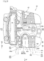
- FIG. 7 which is a sectional plan view of the shell body of the cylinder head 32, taken along line VII - VII of FIG. 5 , the right internally threaded hole 106 is defined in the shell body of the cylinder head 32 at the second inlet pipe mount portion 102.
- the left internally threaded hole 105 is defined in the boss 107 serving as part of the first inlet pipe mount portion 101, rearward (downward in FIG. 7 ) of the right internally threaded hole 106.
- the boss 107 is surrounded by a space for providing a hollow area (a wall thickness reduction for a reduced weight), and is spaced from around the intake port 42, resulting in problems about the fluidity of a molten metal that flows to cast the cylinder head.
- the boss 107 that serves as part of the first inlet pipe mount portion 101 and the partition member 85 (85B) are integrally coupled to each other by a joint 108 extending a shortest distance therebetween.
- the joint 108 lies on the extension of the partition member 85B that extends in the leftward and rightward directions across the intake port 42.
- An intermediate portion, in particular, of the joint 108 has a thickness that substantially corresponds to the thickness of the partition member 85 (85B).
- the joint 108 With the joint 108 being positioned on the extension of the partition member 85B that extends in the leftward and rightward directions across the intake port 42, the overall volume of the portion that includes the boss 107 and the joint 108 is maintained, and the fluidity of a molten metal flowing through the joint 108 is maintained at the time the cylinder head is cast.
- the joint 108 by which the first inlet pipe mount portion 101 and the partition member 85 (85B) are coupled to each other over a shortest distance allows a molten metal introduced to cast the cylinder head to flow from a molding space for casting the cylinder head through the joint 108 that acts as a sprue into the partition member 85 (85B). Furthermore, the fluidity of a molten metal flowing into the partition 85 is increased because the heat of the molten metal is prevented from being absorbed by a mold for forming a hollow area which would otherwise be present between the first inlet pipe mount portion 101 and the partition member 85 (85B).
- FIG. 9 which is a sectional front elevational view of the shell body of the cylinder head 32, taken along line IX - IX of FIGS. 6 and 7 , as viewed rearwardly and downwardly from above the intake port 42 that is in an upper position, the cylinder head 32 has a cavity 32c provided in the vicinity of the spark ignition plug mount 32b on an outer surface 32ao of the combustion chamber ceiling wall 32a.
- the cavity 32c which is provided for air-cooling the cylinder head 32, has openings on the right side of the spark ignition plug mount 32b, the opening side (downward in FIG. 9 ) of the upper intake port 42, and the opening side (upward in FIG. 9 ) of the lower exhaust port 43, for promoting a circulation of ambient air therethrough.
- the opening of the cavity 32c in the cylinder head 32 on the opening side of the intake port 42 i.e., an opening 32d on the side of the first inlet pipe mount portion 101, extends along a peripheral wall 42b of the intake port 42 to a front portion (upward portion in FIGS. 6 and 7 ) of the first inlet pipe mount portion 101, where it is open as shown in FIGS 6 to 8 .
- the boss 107 that serves as the first inlet pipe mount portion 101 is positioned rearward (downward in FIG. 7 ) of the center of the intake port 42 and generally positioned sideways of the partition member 85 (85B).
- the open area of the opening 32d of the cavity 32c in the cylinder head 32 on the side of the first inlet pipe mount portion 101 is thus offset from the first inlet pipe mount portion 101, the open area of the opening 32d of the cavity 32c is increased for a better circulation of ambient air to cool the spark ignition plug mount 32b of the cylinder head 32 well.
- the carburetor is disposed upstream of the inlet pipe.
- the present invention may be applied to an intake structure in which a throttle body is disposed upstream of the inlet pipe and a fuel injection valve is disposed downstream of the throttle body.
- the power unit having the internal combustion engine whose cylinder axis is inclined forward so as to lie essentially horizontally, with the parts disposed in the illustrated lateral layout, has been described above.
- the present invention covers different types of vehicles, power units, and internal combustion engines, internal combustion engines with vertical cylinder axes, and internal combustion engines whose parts are disposed in different lateral layouts, insofar as they fall within the scope of present invention.
- 1 ⁇ Two-wheel motorcycle (scooter-type motorcycle), 2 ⁇ Vehicle body frame, 3 ⁇ Power unit, 6 ⁇ Inlet pipe, 30 ⁇ ⁇ Internal combustion engine (air-cooled internal combustion engine), 31 ⁇ Cylinder block, 31a ⁇ Cylinder bore, 32 ⁇ Cylinder head, 32a ⁇ Combustion chamber ceiling wall, 32ai ⁇ Inner surface, 32ao ⁇ Outer surface, 32b ⁇ Spark ignition plug mount, 32c ⁇ Cavity, 32d ⁇ Opening (of the cavity 32c on the side of the first inlet pipe mount portion 101), 34...Piston, 34a ⁇ Top surface, 36 ⁇ Combustion chamber, 40 ⁇ Intake valve opening, 41 ⁇ Exhaust valve opening, 42 ⁇ Intake port, 42a ⁇ Upstream end face, 43 ⁇ Exhaust port, 46 ⁇ Intake valve, 47 ⁇ Exhaust valve, 50 ⁇ Power unit case, 50a ⁇ Crankcase, 51 ⁇ Crankshaft, 80 ⁇ Intake air-fuel mixture passage, 80a ⁇ Upstream end, 80A ⁇ First
Landscapes
- Engineering & Computer Science (AREA)
- Chemical & Material Sciences (AREA)
- Combustion & Propulsion (AREA)
- Mechanical Engineering (AREA)
- General Engineering & Computer Science (AREA)
- Cylinder Crankcases Of Internal Combustion Engines (AREA)
Abstract
Description
- The present invention relates to an intake structure for use in an internal combustion engine, in which a partition member is integrally formed with an intake port.
- Heretofore, intake structures for internal combustion engines include a continuous intake air-fuel mixture passage provided by an inlet pipe that is connected to the intake port of a cylinder head. One such intake structure, disclosed in
Patent Document 1 mentioned below, for example, has a partition member provided in an intake air passageway in order to generate a tumbling air-fuel mixture flow in the combustion chamber of an internal combustion engine, the partition member dividing the intake air-fuel mixture passage into a tumble flow passageway and a main flow passageway. When the internal combustion engine operates under a low load, an intake air-fuel mixture from the on/off valve of a carburetor is led into the tumble flow passageway to promote the generation of a tumble flow. When the internal combustion engine operates under a high load, an intake air-fuel mixture is led chiefly into the main flow passageway. - With the above intake structure, the cylinder head and the inlet pipe may be made of different materials, and the partition member provided in the intake air-fuel mixture passage may include separate partition members provided respectively in the cylinder head and the inlet pipe.
- For this reason, the partition member provided in the cylinder head and leading to the intake port is often cast integrally with the cylinder head. In such a case, if a hollow or vacant area is formed between the partition member and an inlet pipe mount as in the prior art, then the fluidity of a molten metal, typically molten aluminum, that flows to cast the thin partition member tends to be poor. In addition, the molten aluminum that is about to flow to cast the partition member has its heat absorbed by a mold for forming the hollow or vacant area, so that the molten aluminum tends to solidify before it flows into the partition member.
-
JP H11-210478 A FIGS. 1 ,6 , and 11) - The present invention has been made in view of the above prior art. It is an object of the present invention to provide an intake structure for use in an internal combustion engine including a cylinder head in which a partition member is integrally formed with an intake port, wherein the intake structure is arranged to make it easy to retain the heat of a molten metal when the molten metal is introduced to cast the intake structure, thereby increasing the fluidity of the molten metal introduced to cast the intake structure.
- To achieve the above task, there is provided in accordance with the present invention an intake structure for an internal combustion engine, in which a combustion chamber is defined between a top surface of a piston slidably fitted in a cylinder bore in a cylinder block and an inner surface of a combustion chamber ceiling wall in a cylinder head which is faced by the top surface, and an intake port and an exhaust port extend from an intake valve opening and an exhaust valve opening that are open in the inner surface of the combustion chamber ceiling wall in the cylinder head, the intake port and the exhaust port being curved in directions spaced away from each other. An inlet pipe is connected to the intake port, providing a continuous intake air-fuel mixture passage which is divided into a first intake air-fuel mixture passageway and a second intake air-fuel mixture passageway by a partition, the partition member in the intake port being integrally formed with the cylinder head. The cylinder head has a connection face member for connection to the inlet pipe, the connection face member including an inlet pipe mount portion for receiving an inlet pipe fastening member to be threaded therein, and the inlet pipe mount portion and the partition member of the intake port are integrally formed with each other, and at least part of the inlet pipe mount portion is positioned on an extension of the partition member in a direction across the intake port on an upstream end face of the intake port.
- According to a preferred embodiment of the present invention, the inlet pipe mount portion and the partition member are integrally coupled to each other by a joint. The joint lies on an extension of the partition member extending in leftward and rightward directions across the intake port.
- According to a preferred embodiment of the present invention, the cylinder head has a spark ignition plug mount on an outer surface of the combustion chamber ceiling wall, and a cavity in a region of the spark ignition plug mount, the cylinder head having an opening on the side of the inlet pipe mount portion of the cavity, the opening and the inlet pipe mount portion being offset from each other.
- With the intake structure for an internal combustion engine according to the present invention, in the cylinder head in which the partition member is integrally formed with the intake port, the partition member and the inlet pipe mount portion are brought closely to each other, providing an increased volume in a compact area, so that when the cylinder head is cast, it is easy to retain the heat of a molten metal, and fluidity of the molten metal is increased. In addition, as the partition member and the inlet pipe mount portion are structurally contiguous, the rigidity of and around the inlet pipe mount portion is increased.
- According to the embodiment of the present invention, the joint by which the inlet pipe mount portion and the partition member are coupled to each other allows a molten metal introduced to cast the cylinder head to flow therethrough into the partition member. Furthermore, fluidity of a molten metal flowing into the partition is increased because the heat of the molten metal prevented from being absorbed by a mold for forming a hollow area which would otherwise be present between the inlet pipe mount portion and the partition member.
- According to the embodiment of the present invention, since the inlet pipe mount portion and the opening of the cavity on the side of the inlet pipe mount portion are offset from each other, the open area of the opening of the cavity is increased to cool the spark ignition plug mount of the cylinder head well.
-
-
FIG. 1 is a right-hand side elevational view of a two-wheel scooter-type motorcycle having thereon a power unit that incorporates an intake structure for use in an internal combustion engine according to an embodiment of the present invention; -
FIG. 2 is a right-hand side elevational view of a rear portion of the scooter-type motorcycle shown inFIG. 1 , with a vehicle body cover removed; -
FIG. 3 is a sectional side elevational view of the internal combustion engine of the power unit shown inFIG. 2 , the parts being of the same orientation as those shown inFIG. 2 ; -
FIG. 4 is an enlarged view of a portion of the internal combustion engine shown inFIG. 3 ; -
FIG. 5 is a left-hand side elevational view of the shell body of a cylinder head, the left ofFIG. 5 being oriented forwardly of the vehicle; -
FIG. 6 is a plan view of the shell body of the cylinder head, taken along line VI - VI ofFIG. 5 ; -
FIG. 7 is a sectional plan view of the shell body of the cylinder head, taken along line VII - VII ofFIG. 5 ; -
FIG. 8 is a perspective view of an upper surface of the shell body of the cylinder head, taken along line VIII ofFIG. 5 ; and -
FIG. 9 is a sectional front elevational view of the shell body of the cylinder head, taken along line IX - IX ofFIGS. 6 and7 . - An intake structure for use in an internal combustion engine according to an embodiment of the present invention will be described below with reference to the drawings.
- Forward, rearward, leftward, rightward, upward, and downward directions, and other directional expressions used in the present description and the claims are in accord with those of a vehicle having an internal combustion engine that incorporates the intake structure according to the present embodiment. According to the present embodiment, the vehicle refers to a small-size two-wheel vehicle such as a scooter-type motorcycle, for example.
- In the drawings, FR represents a forward direction of the vehicle, LH a leftward direction of the vehicle, RH a rightward direction of the vehicle, and UP an upward direction of the vehicle.
-
FIG. 1 shows a right-hand side elevational view of a two-wheel scooter-type motorcycle (hereinafter simply referred to as "motorcycle") 1 having a power unit that includes an internal combustion engine according to the present embodiment. - The
motorcycle 1 includes afront vehicle portion 1A and arear vehicle portion 1B that are coupled to each other by alow floor portion 1C, and has a vehicle body including avehicle body frame 2 as a skeletal structure that generally includes adown tube 21 and a pair of left and right main pipes 22 (seeFIG. 2 ). - Specifically, the
down tube 21 extends downward from ahead pipe 20 of thefront vehicle portion 1A and is bent horizontally at a lower end portion thereof and extends rearward below thefloor portion 1C. As shown inFIG. 2 , a pair of the left and rightmain pipes 22 are joined to a rear end of the horizontal portion of thedown tube 21 by ajoint frame 23 extending in widthwise directions of the vehicle. Themain pipes 22 extend obliquely rearward from thejoint frame 23, and are bent at a reduced gradient and extend rearward. - The
main pipes 22 support a rider'sseat 11, a storage case, a fuel tank, and the like beneath the rider'sseat 11, and an area below the rider'sseat 11 is covered with thevehicle body cover 12. - In the
front vehicle portion 1A, ahandle 13 is angularly movably supported on and disposed above thehead pipe 20, and afront fork 14 extends downward from thehead pipe 20, with afront wheel 15 rotatably supported on the lower end of thefront fork 14. - As shown in
FIG. 2 , which is a right-hand side elevational view of a rear portion of themotorcycle 1, with thevehicle body cover 12 removed, abracket 24 projects from the lower ends of the oblique portions of themain pipes 22, and apower unit 3 is swingably joined to and supported on thebracket 24 by alink 25. - The
power unit 3 includes, in its front portion, a single-cylinder four-stroke-cycle air-cooled internal combustion engine (hereinafter referred to as "internal combustion engine") 30. Theinternal combustion engine 30 includes acrankshaft 51 extending in the widthwise directions of the vehicle and rotatably supported in a front portion of apower unit case 50 that serves as acrankcase 50a, and has a cylinder axis X inclined largely forward so as to lie essentially horizontally. Ahanger arm 52 projects forward from the lower end of thepower unit case 50 and has an end coupled to thelink 25 that is mounted to thebracket 24 on themain pipes 22. - The
power unit 3 has theinternal combustion engine 30 inclined largely forward in the front portion of thepower unit case 50 that serves as thecrankcase 50a. Theinternal combustion engine 30 includes acylinder block 31, acylinder head 32, and acylinder head cover 33 that are successively stacked and fastened together. A power transmittingcase 55, including a belt-type continuously variable transmission and the like, extends integrally rearward on the left side from thecrankcase 50a. Arear axle 56 that serves as the output shaft of thepower unit 3 is disposed rearward of the power transmittingcase 55, and arear wheel 16 is mounted on therear axle 56. - A rear cushion, not shown, is interposed between the power transmitting
case 55 in a rear portion of thepower unit 3 and rear portions of themain pipes 22. - As shown in
FIG. 2 , aninlet pipe 6 extends and is curved rearward from an upper portion of thecylinder head 32 that is inclined largely forward of theinternal combustion engine 30 in an upper portion of thepower unit 3. Acarburetor 7 connected to theinlet pipe 6 is positioned above thecylinder block 31. Thecarburetor 7 is connected through aconnecting tube 37 to an air cleaner device, not shown, disposed above the power transmittingcase 55. - An
exhaust pipe 38 extends downward from a lower portion of thecylinder head 32, is bent rearward and shifted to the right, extends rearward, and is connected to amuffler 39 on the right side of therear wheel 16. -
FIG. 3 shows a sectional side elevational view of the front portion of thepower unit 3, i.e., theinternal combustion engine 30, the parts being of the same orientation as those shown inFIG. 2 . Theinternal combustion engine 30 includes apiston 34 movable back and forth in acylinder bore 31a defined in thecylinder block 31, acrankpin 51a on acrankshaft 51, and a connectingrod 35 interconnecting thepiston 34 and thecrankpin 51a. - The
piston 34 that is slidably fitted in thecylinder bore 31a defined in thecylinder block 31 has atop surface 34a that faces an inner surface 32ai of a combustionchamber ceiling wall 32a of thecylinder head 32. Thetop surface 34a and the inner surface 32ai define acombustion chamber 36 therebetween. - According to the present embodiment, the
internal combustion engine 30 incorporates a SOHC-type two-valve system and includes a valve train orvalve operating mechanism 9 provided in thecylinder head 32. - A
cylinder head cover 33 is superposed on and placed over thecylinder head 32 in covering relation to thevalve operating mechanism 9. - T transmit power to the
valve operating mechanism 9 provided in thecylinder head cover 33, an endless cam chain, not shown, is trained around and extends between acamshaft 91 and thecrankshaft 51 through a cam chain compartment 96 (seeFIG. 9 ) provided on one side of thecrankcase 50a, thecylinder block 31, and thecylinder head 32 along thecrankshaft 51. Thecamshaft 91 rotates in synchronism with thecrankshaft 51 at a rotational speed that is one-half of the rotational speed of thecrankshaft 51. - A spark ignition plug, not shown, is inserted into a spark
ignition plug mount 32b (seeFIG. 9 ) from the side of thecylinder head 32 that is opposite thecam chain compartment 96, i.e., from the other side along thecrankshaft 51 toward thecombustion chamber 36. - As shown in
FIG. 3 , thecylinder head 32 that has the cylinder axis X inclined largely forward so as to lie essentially horizontally, includes anintake port 42 and anexhaust port 43 extending respectively from anintake valve opening 40 and an exhaust valve opening 41 that are open in the inner surface 32ai of the combustionchamber ceiling wall 32a. Theintake port 42 and theexhaust port 43 are curved respectively in upward and downward directions spaced away from each other. - The
intake port 42 has anupstream end face 42a facing upward of thecylinder head 32 and connected to theinlet pipe 6, providing a continuous intake air-fuel mixture passage 80. Thecarburetor 7 is connected to an upstream side of theinlet pipe 6. - The
exhaust port 43 has a downstream end facing downward of thecylinder head 32 and coupled to theexhaust pipe 38. - A
tubular valve guide 44 is integrally fitted in a curved outer wall of theintake port 42 in thecylinder head 32. Anintake valve 46 slidably supported in thevalve guide 44 opens and closes the intake valve opening 40 of theintake port 42, which faces thecombustion chamber 36. - An exhaust valve 47 is slidably supported in a
valve guide 45 integrally fitted in a curved outer wall of theexhaust port 43 in thecylinder head 32, and opens and closes the exhaust valve opening 41 of theexhaust port 43, which faces thecombustion chamber 36. - The
intake valve 46 and the exhaust valve 47 are normally biased upward with respect to the engine by valve springs 48 such that theirvalve heads 46a and 47a close theintake valve opening 40 and the exhaust valve opening 41, respectively, that face thecombustion chamber 36. When anintake rocker arm 94 and anexhaust rocker arm 95 that abut respectively against anintake cam 92 and anexhaust cam 93 on thecamshaft 91 are swung, they depress respective stem ends 46b and 47b of the intake andexhaust valves 46 and 47, causing the intake andexhaust valves 46 and 47 to open at predetermined timings to bring theintake port 42 and thecombustion chamber 36 and also theexhaust port 43 and thecombustion chamber 36 into fluid communication with each other for thereby introducing an air-fuel mixture into thecombustion chamber 36 and discharging an exhaust gas from thecombustion chamber 36 at predetermined timings. - In the
internal combustion engine 30 described above according to the present embodiment, the intake air-fuel mixture passage 80 is formed to produce a tumble flow of air-fuel mixture, i.e., a vertical swirl of air-fuel mixture, in thecombustion chamber 36 for achieving preferred combustion in thecombustion chamber 36. - Specifically, the intake air-
fuel mixture passage 80 is divided into a first intake air-fuel mixture passageway 80A and a second intake air-fuel mixture passageway 80B by apartition 85 extending continuously from within theinlet pipe 6 into theintake port 42. The second intake air-fuel mixture passageway 80B is a lower passageway adjoining alower end 71a of an on/offvalve 71 of thecarburetor 71 at the time it is closed, and serves as a tumble flow passageway. The first intake air-fuel mixture passageway 80A is an upper passageway except the second intake air-fuel mixture passageway 80B, and serves as a main flow passageway. - According to the present embodiment, as shown in
FIG. 4 , thecarburetor 7 has aflow passageway 70 having an upstream side connected to the connectingtube 37 and adownstream end 70a connected to anupstream end 6a of theinlet pipe 6, i.e., anupstream end 80a of the intake air-fuel mixture passage 80, through aninsulator 75. The on/offvalve 71, which includes a venturi piston of aventuri unit 72, is provided in theflow passageway 70. Thecarburetor 7 includes a throttle valve 73 (FIG. 3 ) disposed upstream of the on/offvalve 71, and is arranged as a negative-pressure-operatedcarburetor 7. Thecarburetor 7 itself is widely known in the art, and will not be described below. - As shown in
FIG. 4 , which is an enlarged view of a portion of the internal combustion engine shown inFIG. 3 , the on/offvalve 71 closes theflow passageway 70 when it is pressed against the lower end of theflow passageway 70. When the on/offvalve 71 is open, a fuel is drawn from theventuri unit 72, producing an air-fuel mixture that is delivered from a downstream portion of theflow passageway 70 of thecarburetor 7 into theinlet pipe 6, i.e., the intake air-fuel mixture passage 80. - The mixture of air and fuel (hereinafter simply referred to as "intake air") that flows into the intake air-fuel mixture passage when the internal combustion engine operates under a low load is of such a characteristic that it flows, from between the
lower end 71a of thegate valve 71 having a small degree of opening and a bottom 70b of theflow passageway 70, as a sectorial flow along the bottom 70b, and then reaches the intake air-fuel mixture passage 80. - Therefore, when the
internal combustion engine 30 operates under a low load, the intake air is liable to flow into the second intake air-fuel mixture passageway 80B. The second intake air-fuel mixture passageway 80B is arranged to allow the intake air to flow into thecombustion chamber 36 over the back of thevalve head 46a of theintake valve 46 that has been opened, making it easy to produce a tumble flow in thecombustion chamber 36. - When the
internal combustion engine 30 operates under a high load, the on/offvalve 71 of thecarburetor 7 is opened to a large degree, allowing most of the intake air to flow through the first intake air-fuel mixture passageway 80A. Since the intake air flows through the second intake air-fuel mixture passageway 80B at a low flow rate, the intake air flowing through the first intake air-fuel mixture passageway 80A and the intake air flowing through the second intake air-fuel mixture passageway 80B are prevented from colliding with each other in a downstream region of the intake air-fuel mixture passage 80, i.e., in a downstream region of theintake port 42. - As shown in
FIG. 4 , theintake port 42 and theinlet pipe 6 are connected to each other through theinsulator 60. Thepartition 85 includes an inlet-pipe-side partition member 85A, an intake-port-side partition member 85B, and apartition member 85C corresponding to the thickness of theinsulator 60. - The
partition member 85 in theintake port 42 according to the present embodiment, i.e., the intake-port-side partition member 85B, is integrally formed with thecylinder head 32. -
FIG. 5 shows a left-hand side elevational view of the shell body of the cylinder head, as viewed from the side opposite toFIGS. 3 and4 , which are right-hand sectional side elevational views, the left inFIG. 5 being oriented forward of the vehicle. - The
cylinder head 32 has a flatconnection face member 100 on which theinlet pipe 6 is to be mounted with theinsulator 60 interposed therebetween. - As shown in
FIG. 6 , which is a plan view of the shell body of thecylinder head 32, taken along line VI - VI ofFIG. 5 , theconnection face member 100 is in the form of a flange of a tube joint. In order to allow theinlet pipe 6 to be fastened to theconnection face member 100 with theinsulator 60 interposed therebetween, according to the present embodiment, theconnection face member 100 includes a first inletpipe mount portion 101 on its left side and a second inletpipe mount portion 102 on its right side. - The first inlet
pipe mount portion 101 has a left internally threadedhole 105 defined therein for receiving afastening bolt 103 to be threaded therein as a fastening member for theinlet pipe 6, and the second inletpipe mount portion 102 has a right internally threadedhole 106 defined therein for receiving afastening bolt 103 to be threaded therein as a fastening member for theinlet pipe 6. - As shown in
FIG. 8 , which is a perspective view of an upper surface of the shell body of thecylinder head 32, taken along line VIII ofFIG. 5 , theconnection face member 100 includes aright side area 100B where the second inletpipe mount portion 102 is positioned, theright side area 100B being formed of the shell body of thecylinder head 32 itself, as a bulging portion thereof. Therefore, the second inletpipe mount portion 102 is part of the shell body of thecylinder head 32 itself, and the right internally threadedhole 106 is formed in the shell body of thecylinder head 32 from theright side area 100B of theconnection face member 100. - On the other hand, as shown in
FIG. 8 , theconnection face member 100 includes aleft side area 100A where the first inletpipe mount portion 101 is positioned, theleft side area 100A being integrally formed with thecylinder head 32, but formed as a flange-like member 104 extending from the shell body of thecylinder head 32 itself and spaced from an outer surface of the shell body of thecylinder head 32. Therefore, the left internally threadedhole 105 into which thefastening bolt 103 is to be threaded is defined in aboss 107 projecting from the outer surface of the shell body of thecylinder head 32 to theleft side area 100A of theconnection face member 100. - In other words, the first inlet
pipe mount portion 101 includes theboss 107 projecting from the outer surface of the shell body of thecylinder head 32 to theleft side area 100A of theconnection face member 100 and integrally formed with thecylinder head 32 and theleft side area 100A, integrally combining them. - As shown in
FIG. 6 , theupstream end face 42a of theintake port 42 is open substantially upward in theconnection face member 100 at its center in the leftward and rightward directions. The first intake air-fuel mixture passageway 80A is defined in a front portion (upper portion inFIG. 6 ) of theupstream end face 42a, and the second intake air-fuel mixture passageway 80B is defined in a rear portion (lower portion inFIG. 6 ) of theupstream end face 42a, with the partition member 85 (85B) in theintake port 42 being disposed therebetween. - Generally, the first and second inlet
pipe mount portions connection face member 100 are provided in bilateral symmetry with respect to the center of the opening of theintake port 42. In the present embodiment, the first inletpipe mount portion 101, particularly, the area of the left internally threadedhole 105, is shifted toward the second intake air-fuel mixture passageway 80B which is located rearward of the center of the opening of theintake port 42, and is essentially in the same position in the forward and rearward directions as the partition member 85 (85B) that extends in the leftward and rightward directions across theintake port 42. - Specifically, the first inlet
pipe mount portion 101 of theconnection face member 100 and the partition member 85 (85B) in theintake port 42 are integrally formed with each other, and the first inletpipe mount portion 101, particularly, the area of the left internally threadedhole 105, is positioned on an extension of the partition member 85 (85B) that extends in the directions across theintake port 42, on theupstream end face 42a of theintake port 42. - The fact that at least part of the first inlet
pipe mount portion 101 is positioned on an extension of thepartition member 85 on theupstream end face 42a of theintake port 42 offers the following advantages: In thecylinder head 32 in which the partition member 85 (85B) is integrally formed with theintake port 42, the volume of the partition member 85 (85B) and the first inletpipe mount portion 101 is increased, making it easy to retain the heat of a molten metal when the molten metal is introduced to cast the partition member 85 (85B) and the first inletpipe mount portion 101, thereby increasing the fluidity of the molten metal that is introduced to cast the partition member 85 (85B) and the first inletpipe mount portion 101. In addition, as the partition member 85 (85B) and the first inletpipe mount portion 101 are structurally contiguous, the rigidity of and around the first inletpipe mount portion 101 is increased. - Inasmuch as the second inlet
pipe mount portion 102 is formed of the shell body of thecylinder head 32 itself, as a bulging portion thereof, the fluidity of the molten metal that is introduced to cast the second inletpipe mount portion 102 and the rigidity thereof are excellent. - As shown in
FIG. 7 , which is a sectional plan view of the shell body of thecylinder head 32, taken along line VII - VII ofFIG. 5 , the right internally threadedhole 106 is defined in the shell body of thecylinder head 32 at the second inletpipe mount portion 102. The left internally threadedhole 105 is defined in theboss 107 serving as part of the first inletpipe mount portion 101, rearward (downward inFIG. 7 ) of the right internally threadedhole 106. - Heretofore, the
boss 107 is surrounded by a space for providing a hollow area (a wall thickness reduction for a reduced weight), and is spaced from around theintake port 42, resulting in problems about the fluidity of a molten metal that flows to cast the cylinder head. - According to the present embodiment, the
boss 107 that serves as part of the first inletpipe mount portion 101 and the partition member 85 (85B) are integrally coupled to each other by a joint 108 extending a shortest distance therebetween. The joint 108 lies on the extension of thepartition member 85B that extends in the leftward and rightward directions across theintake port 42. An intermediate portion, in particular, of the joint 108 has a thickness that substantially corresponds to the thickness of the partition member 85 (85B). With the joint 108 being positioned on the extension of thepartition member 85B that extends in the leftward and rightward directions across theintake port 42, the overall volume of the portion that includes theboss 107 and the joint 108 is maintained, and the fluidity of a molten metal flowing through the joint 108 is maintained at the time the cylinder head is cast. - Therefore, the joint 108 by which the first inlet
pipe mount portion 101 and the partition member 85 (85B) are coupled to each other over a shortest distance allows a molten metal introduced to cast the cylinder head to flow from a molding space for casting the cylinder head through the joint 108 that acts as a sprue into the partition member 85 (85B). Furthermore, the fluidity of a molten metal flowing into thepartition 85 is increased because the heat of the molten metal is prevented from being absorbed by a mold for forming a hollow area which would otherwise be present between the first inletpipe mount portion 101 and the partition member 85 (85B). - As shown in
FIG. 9 , which is a sectional front elevational view of the shell body of thecylinder head 32, taken along line IX - IX ofFIGS. 6 and7 , as viewed rearwardly and downwardly from above theintake port 42 that is in an upper position, thecylinder head 32 has acavity 32c provided in the vicinity of the sparkignition plug mount 32b on an outer surface 32ao of the combustionchamber ceiling wall 32a. - The
cavity 32c, which is provided for air-cooling thecylinder head 32, has openings on the right side of the sparkignition plug mount 32b, the opening side (downward inFIG. 9 ) of theupper intake port 42, and the opening side (upward inFIG. 9 ) of thelower exhaust port 43, for promoting a circulation of ambient air therethrough. - The opening of the
cavity 32c in thecylinder head 32 on the opening side of theintake port 42, i.e., anopening 32d on the side of the first inletpipe mount portion 101, extends along aperipheral wall 42b of theintake port 42 to a front portion (upward portion inFIGS. 6 and7 ) of the first inletpipe mount portion 101, where it is open as shown inFIGS 6 to 8 . - As can also be seen from
FIG. 7 , theboss 107 that serves as the first inletpipe mount portion 101 is positioned rearward (downward inFIG. 7 ) of the center of theintake port 42 and generally positioned sideways of the partition member 85 (85B). - Since the
opening 32d of thecavity 32c in thecylinder head 32 on the side of the first inletpipe mount portion 101 is thus offset from the first inletpipe mount portion 101, the open area of theopening 32d of thecavity 32c is increased for a better circulation of ambient air to cool the sparkignition plug mount 32b of thecylinder head 32 well. - While the embodiment of the present invention has been described above, the present invention is not limited to the above embodiment, but may be reduced to practice in various forms within the scope of present invention.
- According to the present embodiment, the carburetor is disposed upstream of the inlet pipe. However, the present invention may be applied to an intake structure in which a throttle body is disposed upstream of the inlet pipe and a fuel injection valve is disposed downstream of the throttle body.
- For illustrative purposes, the power unit having the internal combustion engine whose cylinder axis is inclined forward so as to lie essentially horizontally, with the parts disposed in the illustrated lateral layout, has been described above. However, the present invention covers different types of vehicles, power units, and internal combustion engines, internal combustion engines with vertical cylinder axes, and internal combustion engines whose parts are disposed in different lateral layouts, insofar as they fall within the scope of present invention.
- 1···Two-wheel motorcycle (scooter-type motorcycle), 2···Vehicle body frame, 3···Power unit, 6···Inlet pipe, 30· ··Internal combustion engine (air-cooled internal combustion engine), 31···Cylinder block, 31a···Cylinder bore, 32···Cylinder head, 32a···Combustion chamber ceiling wall, 32ai···Inner surface, 32ao···Outer surface, 32b··· Spark ignition plug mount, 32c···Cavity, 32d···Opening (of the
cavity 32c on the side of the first inlet pipe mount portion 101), 34...Piston, 34a···Top surface, 36··· Combustion chamber, 40···Intake valve opening, 41··· Exhaust valve opening, 42···Intake port, 42a···Upstream end face, 43···Exhaust port, 46···Intake valve, 47··· Exhaust valve, 50···Power unit case, 50a···Crankcase, 51··· Crankshaft, 80···Intake air-fuel mixture passage, 80a··· Upstream end, 80A···First intake air-fuel mixture passageway, 80B···Second intake air-fuel mixture passageway, 85···Partition, 85B···Intake-port-side partition member, 100···Connection face member, 101··· First inlet pipe mount portion (inlet pipe mount portion), 103···Fastening bolt (fastening member), 105··· (Left) internally threaded hole, 107···Boss, 108···Joint, X··· Cylinder axis
Claims (4)
- An intake structure for an internal combustion engine, wherein a combustion chamber (36) is defined between a top surface (34a) of a piston (34) slidably fitted in a cylinder bore (31a) in a cylinder block (31) and an inner surface (32ai) of a combustion chamber ceiling wall (32a) in a cylinder head (32) which is faced by the top surface (34a), and an intake port (42) and an exhaust port (43) extend respectively from an intake valve opening (40) and an exhaust valve opening (41) that are open in the inner surface (32ai) of said combustion chamber ceiling wall (32a) in said cylinder head (32), said intake port (42) and said exhaust port (43) being curved in directions spaced away from each other; and
an inlet pipe (6) is connected to said intake port (42), providing a continuous intake air-fuel mixture passage (80) which is divided into a first intake air-fuel mixture passageway (80A) and a second intake air-fuel mixture passageway (80B) by a partition (85), said partition member (85B) in said intake port (42) being integrally formed with said cylinder head (32);
wherein said cylinder head (32) has a connection face member (100) for connection to said inlet pipe (6), said connection face member (100) including an inlet pipe mount portion (101) for receiving an inlet pipe fastening member (103) to be threaded therein; and
the inlet pipe mount portion (101) and said partition member (85B) of said intake port (42) are integrally formed with each other, and at least a part of said inlet pipe mount portion (101) is positioned on an extension of said partition member (85B) in a direction across said intake port (42) on an upstream end face (42a) of said intake port (42). - The intake structure for an internal combustion engine according to claim 1, wherein said inlet pipe mount portion (101) and said partition member (85B) are integrally coupled to each other by a joint (108).
- The intake structure for an internal combustion engine according to claim 2, wherein said joint (108) lies on an extension of said partition member (85B) extending in leftward and rightward directions across said intake port (42).
- The intake structure for an internal combustion engine according to claim 1, 2, or 3, wherein said cylinder head (32) has a spark ignition plug mount (32b) on an outer surface (32ao) of said combustion chamber ceiling wall (32a), and a cavity (32c) in a region of said spark ignition plug mount (32b), said cylinder head (32) having an opening (32d) on a side of said inlet pipe mount portion (101) of said cavity (32c), said opening (32d) and said inlet pipe mount portion (101) being offset from each other.
Applications Claiming Priority (2)
| Application Number | Priority Date | Filing Date | Title |
|---|---|---|---|
| JP2016045800 | 2016-03-09 | ||
| PCT/JP2017/008537 WO2017154782A1 (en) | 2016-03-09 | 2017-03-03 | Internal combustion engine intake structure |
Publications (3)
| Publication Number | Publication Date |
|---|---|
| EP3428433A1 true EP3428433A1 (en) | 2019-01-16 |
| EP3428433A4 EP3428433A4 (en) | 2019-02-27 |
| EP3428433B1 EP3428433B1 (en) | 2020-02-19 |
Family
ID=59789301
Family Applications (1)
| Application Number | Title | Priority Date | Filing Date |
|---|---|---|---|
| EP17763122.3A Active EP3428433B1 (en) | 2016-03-09 | 2017-03-03 | Internal combustion engine intake structure |
Country Status (4)
| Country | Link |
|---|---|
| EP (1) | EP3428433B1 (en) |
| JP (1) | JP6574543B2 (en) |
| CN (1) | CN108779736B (en) |
| WO (1) | WO2017154782A1 (en) |
Cited By (3)
| Publication number | Priority date | Publication date | Assignee | Title |
|---|---|---|---|---|
| EP3650671A4 (en) * | 2017-07-05 | 2020-05-13 | Honda Motor Co., Ltd. | INTAKE STRUCTURE OF INTERNAL COMBUSTION ENGINE |
| EP3650679A4 (en) * | 2017-07-05 | 2020-08-19 | Honda Motor Co., Ltd. | AIR INTAKE STRUCTURE FOR COMBUSTION ENGINE |
| EP4123139A4 (en) * | 2020-03-16 | 2023-07-26 | Honda Motor Co., Ltd. | INTAKE STRUCTURE FOR INTERNAL COMBUSTION ENGINE |
Families Citing this family (2)
| Publication number | Priority date | Publication date | Assignee | Title |
|---|---|---|---|---|
| JP7229334B2 (en) * | 2019-03-01 | 2023-02-27 | 本田技研工業株式会社 | Intake structure of internal combustion engine |
| WO2023053378A1 (en) * | 2021-09-30 | 2023-04-06 | 本田技研工業株式会社 | Air intake structure for internal combustion engine |
Family Cites Families (8)
| Publication number | Priority date | Publication date | Assignee | Title |
|---|---|---|---|---|
| JPS58138255A (en) * | 1982-02-13 | 1983-08-17 | Honda Motor Co Ltd | engine intake system |
| DE19803867A1 (en) * | 1998-01-31 | 1999-08-05 | Volkswagen Ag | Method for manufacturing a cylinder head of an internal combustion engine |
| JP3695401B2 (en) * | 2002-02-13 | 2005-09-14 | 日産自動車株式会社 | Intake device for internal combustion engine |
| JP4657177B2 (en) * | 2006-08-29 | 2011-03-23 | 本田技研工業株式会社 | Internal combustion engine |
| DE102008006681A1 (en) * | 2008-01-30 | 2009-08-06 | Andreas Stihl Ag & Co. Kg | Internal combustion engine with an elastic connecting piece and method for producing an elastic connecting piece |
| CN101633388B (en) * | 2008-07-24 | 2012-09-05 | 雅马哈发动机株式会社 | Automatic tumbrel |
| JP6262587B2 (en) * | 2014-03-28 | 2018-01-17 | 本田技研工業株式会社 | Intake structure of internal combustion engine |
| CN206860281U (en) * | 2016-12-01 | 2018-01-09 | Tvs电机股份有限公司 | Lean-burn formula explosive motor and its adapter |
-
2017
- 2017-03-03 EP EP17763122.3A patent/EP3428433B1/en active Active
- 2017-03-03 JP JP2018504449A patent/JP6574543B2/en active Active
- 2017-03-03 WO PCT/JP2017/008537 patent/WO2017154782A1/en not_active Ceased
- 2017-03-03 CN CN201780015703.3A patent/CN108779736B/en active Active
Cited By (3)
| Publication number | Priority date | Publication date | Assignee | Title |
|---|---|---|---|---|
| EP3650671A4 (en) * | 2017-07-05 | 2020-05-13 | Honda Motor Co., Ltd. | INTAKE STRUCTURE OF INTERNAL COMBUSTION ENGINE |
| EP3650679A4 (en) * | 2017-07-05 | 2020-08-19 | Honda Motor Co., Ltd. | AIR INTAKE STRUCTURE FOR COMBUSTION ENGINE |
| EP4123139A4 (en) * | 2020-03-16 | 2023-07-26 | Honda Motor Co., Ltd. | INTAKE STRUCTURE FOR INTERNAL COMBUSTION ENGINE |
Also Published As
| Publication number | Publication date |
|---|---|
| JP6574543B2 (en) | 2019-09-11 |
| EP3428433B1 (en) | 2020-02-19 |
| CN108779736B (en) | 2020-10-27 |
| CN108779736A (en) | 2018-11-09 |
| WO2017154782A1 (en) | 2017-09-14 |
| EP3428433A4 (en) | 2019-02-27 |
| JPWO2017154782A1 (en) | 2018-11-29 |
Similar Documents
| Publication | Publication Date | Title |
|---|---|---|
| EP3428433B1 (en) | Internal combustion engine intake structure | |
| JP3911950B2 (en) | Motorcycle | |
| US8985072B2 (en) | Piston structure for internal combustion engine | |
| JP2009133320A (en) | Saddle riding type vehicle | |
| EP3594471B1 (en) | Air intake structure for internal combustion engine | |
| US7163074B2 (en) | Motorcycle and engine for motorcycle | |
| US12202566B2 (en) | Straddled vehicle | |
| CN101092897A (en) | Internal combustion engine for vehicle | |
| JP2887797B2 (en) | 4-cycle engine intake system | |
| JPS6249464B2 (en) | ||
| JPS6069256A (en) | Air suction device for 2-cycle multi-cylinder engine | |
| JP2007008357A (en) | Air intake structure for motorcycles | |
| EP3650679B1 (en) | Air intake structure for internal combustion engine | |
| JP5754538B1 (en) | Motorcycle | |
| JPS6228038B2 (en) | ||
| JPS6330198B2 (en) | ||
| WO2021176720A1 (en) | Intake control device for saddle-type vehicle internal combustion engine | |
| CN111608817B (en) | Saddle-ride type internal combustion engine for vehicle | |
| JPS58170627A (en) | Autobicycle | |
| JPH0437249B2 (en) | ||
| JP2607265B2 (en) | 2 cycle engine | |
| JPH0340230B2 (en) | ||
| JP2003278627A (en) | Spark ignition engine with fuel injection valve | |
| JP2524667Y2 (en) | Exhaust system for motorcycle with two-cycle engine | |
| JPS63302143A (en) | Intake system for motorcycles equipped with V-type two-stroke engines |
Legal Events
| Date | Code | Title | Description |
|---|---|---|---|
| STAA | Information on the status of an ep patent application or granted ep patent |
Free format text: STATUS: THE INTERNATIONAL PUBLICATION HAS BEEN MADE |
|
| PUAI | Public reference made under article 153(3) epc to a published international application that has entered the european phase |
Free format text: ORIGINAL CODE: 0009012 |
|
| STAA | Information on the status of an ep patent application or granted ep patent |
Free format text: STATUS: REQUEST FOR EXAMINATION WAS MADE |
|
| 17P | Request for examination filed |
Effective date: 20180905 |
|
| AK | Designated contracting states |
Kind code of ref document: A1 Designated state(s): AL AT BE BG CH CY CZ DE DK EE ES FI FR GB GR HR HU IE IS IT LI LT LU LV MC MK MT NL NO PL PT RO RS SE SI SK SM TR |
|
| AX | Request for extension of the european patent |
Extension state: BA ME |
|
| A4 | Supplementary search report drawn up and despatched |
Effective date: 20190124 |
|
| RIC1 | Information provided on ipc code assigned before grant |
Ipc: F02F 1/42 20060101AFI20190118BHEP Ipc: F02M 35/10 20060101ALI20190118BHEP Ipc: F02B 31/00 20060101ALI20190118BHEP Ipc: F02F 1/32 20060101ALI20190118BHEP |
|
| DAV | Request for validation of the european patent (deleted) | ||
| DAX | Request for extension of the european patent (deleted) | ||
| GRAP | Despatch of communication of intention to grant a patent |
Free format text: ORIGINAL CODE: EPIDOSNIGR1 |
|
| STAA | Information on the status of an ep patent application or granted ep patent |
Free format text: STATUS: GRANT OF PATENT IS INTENDED |
|
| INTG | Intention to grant announced |
Effective date: 20190913 |
|
| GRAS | Grant fee paid |
Free format text: ORIGINAL CODE: EPIDOSNIGR3 |
|
| GRAA | (expected) grant |
Free format text: ORIGINAL CODE: 0009210 |
|
| STAA | Information on the status of an ep patent application or granted ep patent |
Free format text: STATUS: THE PATENT HAS BEEN GRANTED |
|
| AK | Designated contracting states |
Kind code of ref document: B1 Designated state(s): AL AT BE BG CH CY CZ DE DK EE ES FI FR GB GR HR HU IE IS IT LI LT LU LV MC MK MT NL NO PL PT RO RS SE SI SK SM TR |
|
| REG | Reference to a national code |
Ref country code: CH Ref legal event code: EP |
|
| REG | Reference to a national code |
Ref country code: DE Ref legal event code: R096 Ref document number: 602017012061 Country of ref document: DE |
|
| REG | Reference to a national code |
Ref country code: AT Ref legal event code: REF Ref document number: 1235243 Country of ref document: AT Kind code of ref document: T Effective date: 20200315 |
|
| REG | Reference to a national code |
Ref country code: IE Ref legal event code: FG4D |
|
| REG | Reference to a national code |
Ref country code: NL Ref legal event code: MP Effective date: 20200219 |
|
| PG25 | Lapsed in a contracting state [announced via postgrant information from national office to epo] |
Ref country code: RS Free format text: LAPSE BECAUSE OF FAILURE TO SUBMIT A TRANSLATION OF THE DESCRIPTION OR TO PAY THE FEE WITHIN THE PRESCRIBED TIME-LIMIT Effective date: 20200219 Ref country code: FI Free format text: LAPSE BECAUSE OF FAILURE TO SUBMIT A TRANSLATION OF THE DESCRIPTION OR TO PAY THE FEE WITHIN THE PRESCRIBED TIME-LIMIT Effective date: 20200219 Ref country code: NO Free format text: LAPSE BECAUSE OF FAILURE TO SUBMIT A TRANSLATION OF THE DESCRIPTION OR TO PAY THE FEE WITHIN THE PRESCRIBED TIME-LIMIT Effective date: 20200519 |
|
| REG | Reference to a national code |
Ref country code: LT Ref legal event code: MG4D |
|
| PG25 | Lapsed in a contracting state [announced via postgrant information from national office to epo] |
Ref country code: GR Free format text: LAPSE BECAUSE OF FAILURE TO SUBMIT A TRANSLATION OF THE DESCRIPTION OR TO PAY THE FEE WITHIN THE PRESCRIBED TIME-LIMIT Effective date: 20200520 Ref country code: IS Free format text: LAPSE BECAUSE OF FAILURE TO SUBMIT A TRANSLATION OF THE DESCRIPTION OR TO PAY THE FEE WITHIN THE PRESCRIBED TIME-LIMIT Effective date: 20200619 Ref country code: LV Free format text: LAPSE BECAUSE OF FAILURE TO SUBMIT A TRANSLATION OF THE DESCRIPTION OR TO PAY THE FEE WITHIN THE PRESCRIBED TIME-LIMIT Effective date: 20200219 Ref country code: SE Free format text: LAPSE BECAUSE OF FAILURE TO SUBMIT A TRANSLATION OF THE DESCRIPTION OR TO PAY THE FEE WITHIN THE PRESCRIBED TIME-LIMIT Effective date: 20200219 Ref country code: BG Free format text: LAPSE BECAUSE OF FAILURE TO SUBMIT A TRANSLATION OF THE DESCRIPTION OR TO PAY THE FEE WITHIN THE PRESCRIBED TIME-LIMIT Effective date: 20200519 Ref country code: HR Free format text: LAPSE BECAUSE OF FAILURE TO SUBMIT A TRANSLATION OF THE DESCRIPTION OR TO PAY THE FEE WITHIN THE PRESCRIBED TIME-LIMIT Effective date: 20200219 |
|
| PG25 | Lapsed in a contracting state [announced via postgrant information from national office to epo] |
Ref country code: NL Free format text: LAPSE BECAUSE OF FAILURE TO SUBMIT A TRANSLATION OF THE DESCRIPTION OR TO PAY THE FEE WITHIN THE PRESCRIBED TIME-LIMIT Effective date: 20200219 |
|
| REG | Reference to a national code |
Ref country code: DE Ref legal event code: R119 Ref document number: 602017012061 Country of ref document: DE |
|
| PG25 | Lapsed in a contracting state [announced via postgrant information from national office to epo] |
Ref country code: LT Free format text: LAPSE BECAUSE OF FAILURE TO SUBMIT A TRANSLATION OF THE DESCRIPTION OR TO PAY THE FEE WITHIN THE PRESCRIBED TIME-LIMIT Effective date: 20200219 Ref country code: EE Free format text: LAPSE BECAUSE OF FAILURE TO SUBMIT A TRANSLATION OF THE DESCRIPTION OR TO PAY THE FEE WITHIN THE PRESCRIBED TIME-LIMIT Effective date: 20200219 Ref country code: DK Free format text: LAPSE BECAUSE OF FAILURE TO SUBMIT A TRANSLATION OF THE DESCRIPTION OR TO PAY THE FEE WITHIN THE PRESCRIBED TIME-LIMIT Effective date: 20200219 Ref country code: SM Free format text: LAPSE BECAUSE OF FAILURE TO SUBMIT A TRANSLATION OF THE DESCRIPTION OR TO PAY THE FEE WITHIN THE PRESCRIBED TIME-LIMIT Effective date: 20200219 Ref country code: PT Free format text: LAPSE BECAUSE OF FAILURE TO SUBMIT A TRANSLATION OF THE DESCRIPTION OR TO PAY THE FEE WITHIN THE PRESCRIBED TIME-LIMIT Effective date: 20200712 Ref country code: SK Free format text: LAPSE BECAUSE OF FAILURE TO SUBMIT A TRANSLATION OF THE DESCRIPTION OR TO PAY THE FEE WITHIN THE PRESCRIBED TIME-LIMIT Effective date: 20200219 Ref country code: ES Free format text: LAPSE BECAUSE OF FAILURE TO SUBMIT A TRANSLATION OF THE DESCRIPTION OR TO PAY THE FEE WITHIN THE PRESCRIBED TIME-LIMIT Effective date: 20200219 Ref country code: CZ Free format text: LAPSE BECAUSE OF FAILURE TO SUBMIT A TRANSLATION OF THE DESCRIPTION OR TO PAY THE FEE WITHIN THE PRESCRIBED TIME-LIMIT Effective date: 20200219 Ref country code: RO Free format text: LAPSE BECAUSE OF FAILURE TO SUBMIT A TRANSLATION OF THE DESCRIPTION OR TO PAY THE FEE WITHIN THE PRESCRIBED TIME-LIMIT Effective date: 20200219 |
|
| REG | Reference to a national code |
Ref country code: CH Ref legal event code: PL |
|
| REG | Reference to a national code |
Ref country code: AT Ref legal event code: MK05 Ref document number: 1235243 Country of ref document: AT Kind code of ref document: T Effective date: 20200219 |
|
| PG25 | Lapsed in a contracting state [announced via postgrant information from national office to epo] |
Ref country code: MC Free format text: LAPSE BECAUSE OF FAILURE TO SUBMIT A TRANSLATION OF THE DESCRIPTION OR TO PAY THE FEE WITHIN THE PRESCRIBED TIME-LIMIT Effective date: 20200219 |
|
| REG | Reference to a national code |
Ref country code: BE Ref legal event code: MM Effective date: 20200331 |
|
| PLBE | No opposition filed within time limit |
Free format text: ORIGINAL CODE: 0009261 |
|
| STAA | Information on the status of an ep patent application or granted ep patent |
Free format text: STATUS: NO OPPOSITION FILED WITHIN TIME LIMIT |
|
| PG25 | Lapsed in a contracting state [announced via postgrant information from national office to epo] |
Ref country code: LU Free format text: LAPSE BECAUSE OF NON-PAYMENT OF DUE FEES Effective date: 20200303 |
|
| 26N | No opposition filed |
Effective date: 20201120 |
|
| PG25 | Lapsed in a contracting state [announced via postgrant information from national office to epo] |
Ref country code: IE Free format text: LAPSE BECAUSE OF NON-PAYMENT OF DUE FEES Effective date: 20200303 Ref country code: CH Free format text: LAPSE BECAUSE OF NON-PAYMENT OF DUE FEES Effective date: 20200331 Ref country code: DE Free format text: LAPSE BECAUSE OF NON-PAYMENT OF DUE FEES Effective date: 20201001 Ref country code: LI Free format text: LAPSE BECAUSE OF NON-PAYMENT OF DUE FEES Effective date: 20200331 Ref country code: AT Free format text: LAPSE BECAUSE OF FAILURE TO SUBMIT A TRANSLATION OF THE DESCRIPTION OR TO PAY THE FEE WITHIN THE PRESCRIBED TIME-LIMIT Effective date: 20200219 Ref country code: FR Free format text: LAPSE BECAUSE OF NON-PAYMENT OF DUE FEES Effective date: 20200419 |
|
| PG25 | Lapsed in a contracting state [announced via postgrant information from national office to epo] |
Ref country code: SI Free format text: LAPSE BECAUSE OF FAILURE TO SUBMIT A TRANSLATION OF THE DESCRIPTION OR TO PAY THE FEE WITHIN THE PRESCRIBED TIME-LIMIT Effective date: 20200219 Ref country code: BE Free format text: LAPSE BECAUSE OF NON-PAYMENT OF DUE FEES Effective date: 20200331 Ref country code: PL Free format text: LAPSE BECAUSE OF FAILURE TO SUBMIT A TRANSLATION OF THE DESCRIPTION OR TO PAY THE FEE WITHIN THE PRESCRIBED TIME-LIMIT Effective date: 20200219 |
|
| GBPC | Gb: european patent ceased through non-payment of renewal fee |
Effective date: 20210303 |
|
| PG25 | Lapsed in a contracting state [announced via postgrant information from national office to epo] |
Ref country code: GB Free format text: LAPSE BECAUSE OF NON-PAYMENT OF DUE FEES Effective date: 20210303 |
|
| PG25 | Lapsed in a contracting state [announced via postgrant information from national office to epo] |
Ref country code: TR Free format text: LAPSE BECAUSE OF FAILURE TO SUBMIT A TRANSLATION OF THE DESCRIPTION OR TO PAY THE FEE WITHIN THE PRESCRIBED TIME-LIMIT Effective date: 20200219 Ref country code: MT Free format text: LAPSE BECAUSE OF FAILURE TO SUBMIT A TRANSLATION OF THE DESCRIPTION OR TO PAY THE FEE WITHIN THE PRESCRIBED TIME-LIMIT Effective date: 20200219 Ref country code: CY Free format text: LAPSE BECAUSE OF FAILURE TO SUBMIT A TRANSLATION OF THE DESCRIPTION OR TO PAY THE FEE WITHIN THE PRESCRIBED TIME-LIMIT Effective date: 20200219 |
|
| PG25 | Lapsed in a contracting state [announced via postgrant information from national office to epo] |
Ref country code: MK Free format text: LAPSE BECAUSE OF FAILURE TO SUBMIT A TRANSLATION OF THE DESCRIPTION OR TO PAY THE FEE WITHIN THE PRESCRIBED TIME-LIMIT Effective date: 20200219 Ref country code: AL Free format text: LAPSE BECAUSE OF FAILURE TO SUBMIT A TRANSLATION OF THE DESCRIPTION OR TO PAY THE FEE WITHIN THE PRESCRIBED TIME-LIMIT Effective date: 20200219 |
|
| PGFP | Annual fee paid to national office [announced via postgrant information from national office to epo] |
Ref country code: IT Payment date: 20260219 Year of fee payment: 10 |