EP3428407A1 - Ventilsystem für ein fluidleitungssystem in einem flugzeugtriebwerk und verfahren zum betrieb eines ventilsystems für ein fluidleitungssystem in einem flugzeugtriebwerk - Google Patents
Ventilsystem für ein fluidleitungssystem in einem flugzeugtriebwerk und verfahren zum betrieb eines ventilsystems für ein fluidleitungssystem in einem flugzeugtriebwerk Download PDFInfo
- Publication number
- EP3428407A1 EP3428407A1 EP18181212.4A EP18181212A EP3428407A1 EP 3428407 A1 EP3428407 A1 EP 3428407A1 EP 18181212 A EP18181212 A EP 18181212A EP 3428407 A1 EP3428407 A1 EP 3428407A1
- Authority
- EP
- European Patent Office
- Prior art keywords
- valve
- valve system
- control valve
- air
- fluid line
- Prior art date
- Legal status (The legal status is an assumption and is not a legal conclusion. Google has not performed a legal analysis and makes no representation as to the accuracy of the status listed.)
- Withdrawn
Links
Images


Classifications
-
- F—MECHANICAL ENGINEERING; LIGHTING; HEATING; WEAPONS; BLASTING
- F15—FLUID-PRESSURE ACTUATORS; HYDRAULICS OR PNEUMATICS IN GENERAL
- F15B—SYSTEMS ACTING BY MEANS OF FLUIDS IN GENERAL; FLUID-PRESSURE ACTUATORS, e.g. SERVOMOTORS; DETAILS OF FLUID-PRESSURE SYSTEMS, NOT OTHERWISE PROVIDED FOR
- F15B15/00—Fluid-actuated devices for displacing a member from one position to another; Gearing associated therewith
- F15B15/20—Other details, e.g. assembly with regulating devices
- F15B15/28—Means for indicating the position, e.g. end of stroke
- F15B15/2815—Position sensing, i.e. means for continuous measurement of position, e.g. LVDT
- F15B15/2861—Position sensing, i.e. means for continuous measurement of position, e.g. LVDT using magnetic means
-
- F—MECHANICAL ENGINEERING; LIGHTING; HEATING; WEAPONS; BLASTING
- F01—MACHINES OR ENGINES IN GENERAL; ENGINE PLANTS IN GENERAL; STEAM ENGINES
- F01D—NON-POSITIVE DISPLACEMENT MACHINES OR ENGINES, e.g. STEAM TURBINES
- F01D17/00—Regulating or controlling by varying flow
- F01D17/02—Arrangement of sensing elements
- F01D17/08—Arrangement of sensing elements responsive to condition of working-fluid, e.g. pressure
- F01D17/085—Arrangement of sensing elements responsive to condition of working-fluid, e.g. pressure to temperature
-
- F—MECHANICAL ENGINEERING; LIGHTING; HEATING; WEAPONS; BLASTING
- F01—MACHINES OR ENGINES IN GENERAL; ENGINE PLANTS IN GENERAL; STEAM ENGINES
- F01D—NON-POSITIVE DISPLACEMENT MACHINES OR ENGINES, e.g. STEAM TURBINES
- F01D17/00—Regulating or controlling by varying flow
- F01D17/10—Final actuators
- F01D17/105—Final actuators by passing part of the fluid
-
- F—MECHANICAL ENGINEERING; LIGHTING; HEATING; WEAPONS; BLASTING
- F02—COMBUSTION ENGINES; HOT-GAS OR COMBUSTION-PRODUCT ENGINE PLANTS
- F02C—GAS-TURBINE PLANTS; AIR INTAKES FOR JET-PROPULSION PLANTS; CONTROLLING FUEL SUPPLY IN AIR-BREATHING JET-PROPULSION PLANTS
- F02C6/00—Plural gas-turbine plants; Combinations of gas-turbine plants with other apparatus; Adaptations of gas-turbine plants for special use
- F02C6/04—Gas-turbine plants providing heated or pressurised working fluid for other apparatus, e.g. without mechanical power output
- F02C6/06—Gas-turbine plants providing heated or pressurised working fluid for other apparatus, e.g. without mechanical power output providing compressed gas
- F02C6/08—Gas-turbine plants providing heated or pressurised working fluid for other apparatus, e.g. without mechanical power output providing compressed gas the gas being bled from the gas-turbine compressor
-
- F—MECHANICAL ENGINEERING; LIGHTING; HEATING; WEAPONS; BLASTING
- F02—COMBUSTION ENGINES; HOT-GAS OR COMBUSTION-PRODUCT ENGINE PLANTS
- F02C—GAS-TURBINE PLANTS; AIR INTAKES FOR JET-PROPULSION PLANTS; CONTROLLING FUEL SUPPLY IN AIR-BREATHING JET-PROPULSION PLANTS
- F02C7/00—Features, components parts, details or accessories, not provided for in, or of interest apart form groups F02C1/00 - F02C6/00; Air intakes for jet-propulsion plants
- F02C7/12—Cooling of plants
- F02C7/16—Cooling of plants characterised by cooling medium
- F02C7/18—Cooling of plants characterised by cooling medium the medium being gaseous, e.g. air
-
- F—MECHANICAL ENGINEERING; LIGHTING; HEATING; WEAPONS; BLASTING
- F02—COMBUSTION ENGINES; HOT-GAS OR COMBUSTION-PRODUCT ENGINE PLANTS
- F02C—GAS-TURBINE PLANTS; AIR INTAKES FOR JET-PROPULSION PLANTS; CONTROLLING FUEL SUPPLY IN AIR-BREATHING JET-PROPULSION PLANTS
- F02C9/00—Controlling gas-turbine plants; Controlling fuel supply in air- breathing jet-propulsion plants
- F02C9/16—Control of working fluid flow
- F02C9/18—Control of working fluid flow by bleeding, bypassing or acting on variable working fluid interconnections between turbines or compressors or their stages
-
- F—MECHANICAL ENGINEERING; LIGHTING; HEATING; WEAPONS; BLASTING
- F15—FLUID-PRESSURE ACTUATORS; HYDRAULICS OR PNEUMATICS IN GENERAL
- F15B—SYSTEMS ACTING BY MEANS OF FLUIDS IN GENERAL; FLUID-PRESSURE ACTUATORS, e.g. SERVOMOTORS; DETAILS OF FLUID-PRESSURE SYSTEMS, NOT OTHERWISE PROVIDED FOR
- F15B15/00—Fluid-actuated devices for displacing a member from one position to another; Gearing associated therewith
- F15B15/20—Other details, e.g. assembly with regulating devices
- F15B15/28—Means for indicating the position, e.g. end of stroke
- F15B15/2815—Position sensing, i.e. means for continuous measurement of position, e.g. LVDT
- F15B15/2869—Position sensing, i.e. means for continuous measurement of position, e.g. LVDT using electromagnetic radiation, e.g. radar or microwaves
- F15B15/2876—Position sensing, i.e. means for continuous measurement of position, e.g. LVDT using electromagnetic radiation, e.g. radar or microwaves using optical means, e.g. laser
-
- F—MECHANICAL ENGINEERING; LIGHTING; HEATING; WEAPONS; BLASTING
- F16—ENGINEERING ELEMENTS AND UNITS; GENERAL MEASURES FOR PRODUCING AND MAINTAINING EFFECTIVE FUNCTIONING OF MACHINES OR INSTALLATIONS; THERMAL INSULATION IN GENERAL
- F16K—VALVES; TAPS; COCKS; ACTUATING-FLOATS; DEVICES FOR VENTING OR AERATING
- F16K1/00—Lift valves or globe valves, i.e. cut-off apparatus with closure members having at least a component of their opening and closing motion perpendicular to the closing faces
- F16K1/16—Lift valves or globe valves, i.e. cut-off apparatus with closure members having at least a component of their opening and closing motion perpendicular to the closing faces with pivoted closure-members
- F16K1/18—Lift valves or globe valves, i.e. cut-off apparatus with closure members having at least a component of their opening and closing motion perpendicular to the closing faces with pivoted closure-members with pivoted discs or flaps
- F16K1/22—Lift valves or globe valves, i.e. cut-off apparatus with closure members having at least a component of their opening and closing motion perpendicular to the closing faces with pivoted closure-members with pivoted discs or flaps with axis of rotation crossing the valve member, e.g. butterfly valves
- F16K1/221—Lift valves or globe valves, i.e. cut-off apparatus with closure members having at least a component of their opening and closing motion perpendicular to the closing faces with pivoted closure-members with pivoted discs or flaps with axis of rotation crossing the valve member, e.g. butterfly valves specially adapted operating means therefor
-
- F—MECHANICAL ENGINEERING; LIGHTING; HEATING; WEAPONS; BLASTING
- F16—ENGINEERING ELEMENTS AND UNITS; GENERAL MEASURES FOR PRODUCING AND MAINTAINING EFFECTIVE FUNCTIONING OF MACHINES OR INSTALLATIONS; THERMAL INSULATION IN GENERAL
- F16K—VALVES; TAPS; COCKS; ACTUATING-FLOATS; DEVICES FOR VENTING OR AERATING
- F16K37/00—Special means in or on valves or other cut-off apparatus for indicating or recording operation thereof, or for enabling an alarm to be given
-
- F—MECHANICAL ENGINEERING; LIGHTING; HEATING; WEAPONS; BLASTING
- F16—ENGINEERING ELEMENTS AND UNITS; GENERAL MEASURES FOR PRODUCING AND MAINTAINING EFFECTIVE FUNCTIONING OF MACHINES OR INSTALLATIONS; THERMAL INSULATION IN GENERAL
- F16K—VALVES; TAPS; COCKS; ACTUATING-FLOATS; DEVICES FOR VENTING OR AERATING
- F16K37/00—Special means in or on valves or other cut-off apparatus for indicating or recording operation thereof, or for enabling an alarm to be given
- F16K37/0008—Mechanical means
-
- F—MECHANICAL ENGINEERING; LIGHTING; HEATING; WEAPONS; BLASTING
- F16—ENGINEERING ELEMENTS AND UNITS; GENERAL MEASURES FOR PRODUCING AND MAINTAINING EFFECTIVE FUNCTIONING OF MACHINES OR INSTALLATIONS; THERMAL INSULATION IN GENERAL
- F16K—VALVES; TAPS; COCKS; ACTUATING-FLOATS; DEVICES FOR VENTING OR AERATING
- F16K37/00—Special means in or on valves or other cut-off apparatus for indicating or recording operation thereof, or for enabling an alarm to be given
- F16K37/0025—Electrical or magnetic means
- F16K37/0041—Electrical or magnetic means for measuring valve parameters
-
- F—MECHANICAL ENGINEERING; LIGHTING; HEATING; WEAPONS; BLASTING
- F16—ENGINEERING ELEMENTS AND UNITS; GENERAL MEASURES FOR PRODUCING AND MAINTAINING EFFECTIVE FUNCTIONING OF MACHINES OR INSTALLATIONS; THERMAL INSULATION IN GENERAL
- F16K—VALVES; TAPS; COCKS; ACTUATING-FLOATS; DEVICES FOR VENTING OR AERATING
- F16K37/00—Special means in or on valves or other cut-off apparatus for indicating or recording operation thereof, or for enabling an alarm to be given
- F16K37/0058—Optical means, e.g. light transmission, observation ports
-
- F—MECHANICAL ENGINEERING; LIGHTING; HEATING; WEAPONS; BLASTING
- F05—INDEXING SCHEMES RELATING TO ENGINES OR PUMPS IN VARIOUS SUBCLASSES OF CLASSES F01-F04
- F05D—INDEXING SCHEME FOR ASPECTS RELATING TO NON-POSITIVE-DISPLACEMENT MACHINES OR ENGINES, GAS-TURBINES OR JET-PROPULSION PLANTS
- F05D2270/00—Control
- F05D2270/01—Purpose of the control system
- F05D2270/09—Purpose of the control system to cope with emergencies
-
- F—MECHANICAL ENGINEERING; LIGHTING; HEATING; WEAPONS; BLASTING
- F05—INDEXING SCHEMES RELATING TO ENGINES OR PUMPS IN VARIOUS SUBCLASSES OF CLASSES F01-F04
- F05D—INDEXING SCHEME FOR ASPECTS RELATING TO NON-POSITIVE-DISPLACEMENT MACHINES OR ENGINES, GAS-TURBINES OR JET-PROPULSION PLANTS
- F05D2270/00—Control
- F05D2270/30—Control parameters, e.g. input parameters
- F05D2270/301—Pressure
-
- F—MECHANICAL ENGINEERING; LIGHTING; HEATING; WEAPONS; BLASTING
- F05—INDEXING SCHEMES RELATING TO ENGINES OR PUMPS IN VARIOUS SUBCLASSES OF CLASSES F01-F04
- F05D—INDEXING SCHEME FOR ASPECTS RELATING TO NON-POSITIVE-DISPLACEMENT MACHINES OR ENGINES, GAS-TURBINES OR JET-PROPULSION PLANTS
- F05D2270/00—Control
- F05D2270/30—Control parameters, e.g. input parameters
- F05D2270/303—Temperature
-
- Y—GENERAL TAGGING OF NEW TECHNOLOGICAL DEVELOPMENTS; GENERAL TAGGING OF CROSS-SECTIONAL TECHNOLOGIES SPANNING OVER SEVERAL SECTIONS OF THE IPC; TECHNICAL SUBJECTS COVERED BY FORMER USPC CROSS-REFERENCE ART COLLECTIONS [XRACs] AND DIGESTS
- Y02—TECHNOLOGIES OR APPLICATIONS FOR MITIGATION OR ADAPTATION AGAINST CLIMATE CHANGE
- Y02T—CLIMATE CHANGE MITIGATION TECHNOLOGIES RELATED TO TRANSPORTATION
- Y02T50/00—Aeronautics or air transport
- Y02T50/60—Efficient propulsion technologies, e.g. for aircraft
Definitions
- the invention relates to a valve system for a fluid line system in an aircraft engine having the features of claim 1 and to a method for operating a valve system for a fluid line system in an aircraft engine having the features of claim 10.
- a plurality of fluids are routed through fluid conduit systems.
- An example of such a fluid conduit system is the so-called secondary air system, which includes all air ducts in the aircraft engine, which do not contribute directly to the thrust of the aircraft engine.
- the secondary air system carries e.g. Cooling air and / or sealing air in the areas of the aircraft engine in which the air is needed.
- Cooling air is typically used to cool turbine blades, turbine disks and / or the turbine housing (eg as part of a tip clearance control).
- Barrier air is used e.g. for fluid dynamic sealing of spaces in the turbine area, e.g. against the penetration of hot gases.
- the object is to efficiently guide or control fluids within the aircraft engine and to provide fluid conduit systems that are particularly robust against failure of a fluid conduit.
- the valve position of an actuating element in the at least one control valve in response to the respectively impressed on the at least one control valve pressure conditions changeable, in particular automatically changeable.
- a monitoring means detects the respective valve position, in particular an open position and / or closed position of the actuating element, as a function of at least one measured value, wherein a signal is emitted as a function of the detected valve position.
- the at least one measured value is a temperature value, a pressure value and / or a flow velocity value.
- a sensor in particular at least one temperature sensor, at least one pressure sensor and / or at least one flow rate sensor is arranged upstream and / or downstream of the at least one control valve.
- a deviation of the measured values from given and / or determined reference measured values is determined.
- absolute measurements need not be used for monitoring, but suitably scaled values can be used.
- the signal for the valve position may be magnetically, optically, haptically and / or mechanically displayable.
- the signal may e.g. be performed on the flight data processing of the aircraft engine, so that a corresponding valve position in the Maintenance Recorder or in the cockpit can be displayed.
- Embodiments of the valve system may comprise at least one control valve with a double flap, a rotary flap and / or a ball as a control element for the fluid. With these control elements, an efficient opening and closing of the fluid line can be achieved.
- air in particular cooling air and / or blocking air, may be the fluid which flows through the fluid line.
- the fluid line can lead air from a compressor stage to a turbine stage, in particular a high-pressure turbine of the aircraft engine. Especially in the field of high-pressure turbine high temperatures are present, so that an efficient cooling air supply makes sense.
- the at least one control valve is arranged in spatial proximity to a turbine stage.
- the object is also achieved by a method for operating a valve system for a fluid line system in an aircraft engine.
- valve position of an actuating element in the at least one control valve is changed as a function of the respectively impressed on the at least one control valve pressure ratios, in particular automatically changed and with a monitoring means the respective valve position, in particular the open position and / or the closed position of the control element, as a function of at least one measured value is monitored, depending on the detected valve position then emit a signal and a minimum necessary purge air flow is set.
- the measured value can e.g. a temperature value, a pressure value and / or a flow velocity value.
- At least one measured value can be measured upstream and / or downstream of the at least one control valve.
- the monitoring means may determine a deviation of the measured values from given and / or determined reference measured values during the processing of the measured values. This determination of the deviation is a comparatively simple measure.
- valve position signal may be e.g. be displayed magnetically, optically, haptically and / or mechanically.
- the fluid is air, in particular cooling air and / or sealing air. These media are needed in aircraft engines.
- Fig. 1 is shown in part a part of an aircraft engine.
- a fluid line 10 which here leads an air flow L from a compressor stage 11 to a turbine stage 12.
- the air flow L is removed at the compressor stage 11, wherein the air duct is guided here by the - at least in the side view - substantially U-shaped fluid line 10.
- the destination of the comparatively cool air from the compressor stage 11 is a space around one of the disks of the turbine stage.
- a part of the air flow L is used as cooling air.
- a control valve 1 Before entering the area of the turbine stage 12, namely before the entry of the air into the space around one of the turbine disks and the space for sealing air, a control valve 1 is arranged as part of a valve system.
- the presentation of the Fig. 1 is to be understood as an example.
- the aircraft engine may have a different design (eg a different number of compressor and / or turbine stages).
- the fluid conduit 10 may tap air at another location and / or guide it to another location where it is used, for example, as cooling air or sealing air.
- the shapes of the fluid lines 10 may be different, in particular, they may be more complex, so that, for example, air is discharged from several points in the aircraft engine and / or distributed to several locations.
- the fluid line 10 is formed as a tube with a circular cross-section.
- other cross sections eg polygonal, elliptical
- the cross section changes along the flow in the air line 10.
- the fluid conduit can also be liquid media, such as e.g. Hydraulic fluid or oil.
- control valve 1 within the embodiments of the valve system will be described in more detail below.
- control valves 1 in the sense of the following embodiments are shut-off valves, quick-acting valves, check valves or shut-off valves which enable or prevent a fluid flow, in which case the control valves 1 are automatically controlled in particular as a function of pressure conditions applied to the control valve 1 ,
- Fig. 1 For reasons of simplicity, only one check valve 1 is shown on the input flange of the turbine housing. In principle, more than one control valve 1 can be used. It is also possible to arrange one or more control valves at other locations of the fluid lines 1.
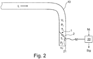
- Fig. 2 is shown in a schematic representation of the structure of an embodiment of a valve system for a fluid line system. Basically, in each case to relevant parts of the description of Fig. 1 Be referred.
- the fluid line system here has a fluid line 10 through which - as in the embodiment of Fig. 1 - Air is guided.
- a control valve 1 in the form of a rotary valve with an actuator 2 is arranged.
- the two valve positions (S1, S2) of the rotary valve are in the FIGS. 2A and 2B shown.
- the check valve 1 is open (S1), in Fig. 2B closed (S2).
- a check valve in the form of a flap instead of the butterfly valve, e.g. a check valve in the form of a flap used.
- valve position S1, S2 of the control element 2 in the control valve 1 in response to the respectively impressed on the control valve 1 pressure conditions P1, P2 can be changed. Should be e.g. due to a break or a leak, a pressure difference (
- Fig. 1 It has been shown that the control valve 1 is located spatially upstream of the turbine stage 12.
- the rapid closing of the check valve 1 causes the air (ie, the cooling air and the purging air) to remain in the respective areas and can not flow back. Cooling and blocking air could then still flow into the spaces in the region of the turbine disks 12 through other fluid lines 1.
- valve position S1, S2 open, closed
- a sensor 21 is used to measure at least one temperature T, pressure P, and / or velocity v in the fluid conduit 10 in the vicinity of the control valve 1 (upstream and / or downstream).
- This measured value M (i.e., the absolute value) will be different for the case of a closed and an open control valve 1, respectively, so that monitoring of the valve position S1, S2 is possible.
- the measured values M are sent to a monitoring means 20, e.g. a microcomputer, which can process the measured values M and / or store.
- the state of the valve position S1, S2 can then be transmitted in the form of a signal Sig to an optical, mechanical, haptic and / or acoustic reproduction device (not shown here).
- the monitoring of the valve positions S1, S2 can also take place as a function of a deviation of the measured values M from a reference measured value Mr.
- the reference measurement Mr may be e.g. may be a set point or an average value measured by the monitoring means 20 for a certain period of time.
- the monitoring means 20 can also be used to ensure the minimum sealing air supply should a fluid line 10 be closed by the control valve 1 (ie, there is a corresponding signal Sig). This can be done, for example, by conveying correspondingly more air into the spaces around the turbine stage via other fluid lines.
Landscapes
- Engineering & Computer Science (AREA)
- General Engineering & Computer Science (AREA)
- Mechanical Engineering (AREA)
- Chemical & Material Sciences (AREA)
- Combustion & Propulsion (AREA)
- Physics & Mathematics (AREA)
- Fluid Mechanics (AREA)
- Optics & Photonics (AREA)
- Health & Medical Sciences (AREA)
- Electromagnetism (AREA)
- Radar, Positioning & Navigation (AREA)
- Remote Sensing (AREA)
- Toxicology (AREA)
- Indication Of The Valve Opening Or Closing Status (AREA)
- Fluid-Driven Valves (AREA)
Abstract
Description
- Die Erfindung betrifft ein Ventilsystem für ein Fluidleitungssystem in einem Flugzeugtriebwerk mit den Merkmalen des Anspruchs 1 und ein Verfahren zum Betrieb eines Ventilsystems für ein Fluidleitungssystem in einem Flugzeugtriebwerk mit den Merkmalen des Anspruchs 10.
- In einem Flugzeugtriebwerk wird eine Vielzahl von Fluiden (z.B. Hydraulikflüssigkeit, Öl, Luft) durch Fluidleitungssysteme geführt. Ein Beispiel für ein solches Fluidleitungssystem ist das sogenannte Sekundär-Luftsystem (secondary air system), das alle Luftführungen im Flugzeugtriebwerk umfasst, die nicht unmittelbar zum Schub des Flugzeugtriebwerkes beitragen. Das Sekundär-Luftsystem führt z.B. Kühlluft und / oder Sperrluft in die Bereiche des Flugzeugtriebwerks, in denen die Luft benötigt wird.
- Kühlluft wird typischerweise zur Kühlung von Turbinenschaufeln, Turbinenscheiben und / oder dem Turbinengehäuse (z.B. im Rahmen einer Schaufelspitzenspaltkontrolle (Tip Clearance Control) verwendet.
- Sperrluft dient z.B. zurfluiddynamischen Abdichtung von Räumen im Turbinenbereich, z.B. gegenüber dem Eindringen heißer Gase.
- Daher besteht die Aufgabe, Fluide innerhalb des Flugzeugtriebwerkes effizient zu führen oder zu steuern und Fluidleitungssysteme zu schaffen, die insbesondere auch robust gegenüber einem Versagen einer Fluidleitung sind.
- Die Aufgabe wird durch ein Ventilsystem mit den Merkmalen des Anspruchs 1 gelöst.
- Dabei ist im Ventilsystem die Ventilstellung eines Stellelementes im mindestens einen Kontrollventil in Abhängigkeit der jeweils auf das mindestens eine Kontrollventil aufgeprägten Druckverhältnisse änderbar, insbesondere automatisch änderbar. Und ein Überwachungsmittel erfasst die jeweilige Ventilstellung, insbesondere eine Offenstellung und / oder Geschlossenstellung des Stellelementes, in Abhängigkeit mindestens eines Messwertes, wobei in Abhängigkeit der erfassten Ventilstellung ein Signal abgeben wird. Durch die Verwendung einer Messwertüberwachung ist eine effiziente und nicht-invasive Überwachung der Ventilstellungen möglich. Damit kann z.B. effizient auf ein mögliches Versagen der Fluidleitungen, insbesondere von Luftleitungen, reagiert werden. Ein Mittel, z.B. das Überwachungsmittel, wird dazu verwendet, ein Einstellen eines minimal notwendigen Sperrluftstroms zu erreichen. Damit kann verhindert werden, dass der Druck lokal zu weit abfällt.
- In einer Ausführungsform ist der mindestens eine Messwert ein Temperaturwert, ein Druckwert und / oder ein Strömungsgeschwindigkeitswert. Es ist insbesondere auch möglich, mehrere unterschiedliche Messwerte zu verwenden und Korrelationen zwischen den Messwerten auszunutzen.
- In einer Ausführungsform ist ein Sensor, insbesondere mindestens ein Temperatursensor, mindestens ein Drucksensor und / oder mindestens ein Strömungsgeschwindigkeitssensor stromaufwärts und / oder stromabwärts des mindestens einen Kontrollventils angeordnet.
- Auch wird in einer Ausführungsform des Ventilsystems mit dem Überwachungsmittel bei der Verarbeitung der Messwerte eine Abweichung der Messwerte von gegebenen und / oder ermittelten Referenzmesswerten ermittelt. Somit müssen nicht absolute Messwerte zur Überwachung verwendet werden, sondern es können geeignet skalierte Werte verwendet werden.
- Ferner ist es in einer Ausführungsform möglich, dass das Signal für die Ventilstellung magnetisch, optisch, haptisch und / oder mechanisch anzeigbar ist. Das Signal kann z.B. über die Flugdatenverarbeitung des Flugzeugtriebwerks geführt werden, so dass eine entsprechende Ventilstellung im Maintenance Recorder oder auch im Cockpit anzeigbar ist.
- Ausführungsformen des Ventilsystems können mindestens ein Kontrollventil mit einer Doppelklappe, einer Drehklappe und / oder einer Kugel als Stellelement für das Fluid aufweisen. Mit diesen Stellelementen kann ein effizientes Öffnen und Schließen der Fluidleitung erreicht werden.
- Dabei kann in einer Ausführungsform Luft, insbesondere Kühlluft und / oder Sperrluft das Fluid sein, das durch die Fluidleitung strömt.
- Dabei kann die Fluidleitung in einer Ausführungsform Luft von einer Kompressorstufe zu einer Turbinenstufe, insbesondere einer Hochdruckturbine des Flugzeugtriebwerkes, führen. Gerade im Bereich der Hochdruckturbine liegen hohe Temperaturen vor, so dass eine effiziente Kühlluftzufuhr sinnvoll ist. In einer weiteren Ausführungsform ist das mindestens eine Kontrollventil in räumlicher Nähe zu einer Turbinenstufe angeordnet.
- Die Aufgabe wird auch durch ein Verfahren zum Betreiben eines Ventilsystems für ein Fluidleitungssystem in einem Flugzeugtriebwerk gelöst.
- Dabei wird die Ventilstellung eines Stellelementes im mindestens einen Kontrollventil in Abhängigkeit der jeweils auf das mindestens eine Kontrollventil aufgeprägten Druckverhältnisse geändert, insbesondere automatisch geändert und mit einem Überwachungsmittel die jeweilige Ventilstellung, insbesondere die Offenstellung und / oder die Geschlossenstellung des Stellelementes, in Abhängigkeit mindestens eines Messwertes überwacht wird, wobei in Abhängigkeit der erfassten Ventilstellung dann ein Signal abgeben wird und ein minimal notwendiger Sperrluftstrom eingestellt wird.
- Der Messwert kann z.B. ein Temperaturwert, ein Druckwert und / oder ein Strömungsgeschwindigkeitswert sein.
- Dabei kann z.B. mindestens ein Messwert stromaufwärts und / oder stromabwärts des mindestens einen Kontrollventils gemessen werden.
- Auch kann in einer Ausführungsform das Überwachungsmittel bei der Verarbeitung der Messwerte eine Abweichung der Messwerte von gegebenen und / oder ermittelten Referenzmesswerten ermitteln. Diese Ermittlung der Abweichung ist eine vergleichsweise einfache Maßnahme.
- Auch kann das Signal für die Ventilstellung z.B. magnetisch, optisch, haptisch und / oder mechanisch angezeigt werden.
- In einer Ausführungsform des Verfahrens ist das Fluid Luft, insbesondere Kühlluft und / oder Sperrluft. Diese Medien werden in Flugzeugtriebwerken benötigt.
- In Zusammenhang mit den in den Figuren dargestellten Ausführungsbeispielen wird die Erfindung erläutert. Dabei zeigt
-
Fig. 1 eine schematische Schnittansicht durch einen Teil eines Flugzeugtriebwerkes mit einem Teil eines Sekundär-Luftsystems; -
Fig. 2 eine schematische Schnittansicht einer Ausführungsform eines Ventilsystems im Sekundär-Luftsystems mit einem Kontrollventil; -
Fig. 2A eine schematische Schnittansicht eines Kontrollventils in offener Ventilstellung; -
Fig. 2B eine schematische Schnittansicht eines Kontrollventils in geschlossener Ventilstellung. - In
Fig. 1 ist ausschnittsweise ein Teil eines Flugzeugtriebwerkes dargestellt. In der dargestellten Ausführungsform ist exemplarisch eine Fluidleitung 10 dargestellt, die hier einen Luftstrom L von einer Kompressorstufe 11 zu einer Turbinenstufe 12 führt. Der Luftstrom L wird an der Kompressorstufe 11 entnommen, wobei die Luftführung hier durch die - zumindest in der Seitenansicht - im Wesentlichen U-förmige Fluidleitung 10 geführt wird. Der Zielort der vergleichsweise kühlen Luft aus der Kompressorstufe 11 ist ein Raum um eine der Scheiben der Turbinenstufe. Hier wird ein Teil des Luftstroms L als Kühlluft eingesetzt. - Auch wird ein Teil des Luftstroms L noch weiter in das Innere des Flugzeugtriebwerks geführt, nämlich in einen Raum für Sperrluft. Damit können z.B. Lager vor dem Eintritt von Heißgasen geschützt werden.
- Vor dem Eintritt in den Bereich der Turbinenstufe 12, nämlich vor dem Eintritt der Luft in den Raum um eine der Turbinenscheiben und den Raum für Sperrluft, ist ein Kontrollventil 1 als Teil eines Ventilsystems angeordnet.
- Die Darstellung der
Fig. 1 ist beispielhaft zu verstehen. Das Flugzeugtriebwerk kann eine andere Bauform haben (z.B. eine andere Anzahl von Kompressor- und / oder Turbinenstufen). Auch kann die Fluidleitung 10 Luft an einem anderen Ort abzapfen und / oder sie zu einem anderen Ort führen, wo sie z.B. als Kühlluft oder Sperrluft verwendet wird. Auch die Formen der Fluidleitungen 10 können anders, insbesondere kann sie komplexer, sein, so dass z.B. Luft von mehreren Stellen im Flugzeugtriebwerk abgeführt wird und / oder zu mehreren Stellen verteilt wird. - In der Ausführungsform der
Fig. 1 ist die Fluidleitung 10 als Rohr mit einem kreisförmigen Querschnitt ausgebildet. In anderen Ausführungsformen sind auch andere Querschnitte (z.B. polygonal, elliptisch) möglich. Auch ist es möglich, dass sich der Querschnitt entlang der Strömung in der Luftleitung 10 ändert. - Grundsätzlich kann die Fluidleitung in einer anderen Ausführungsform des Ventilsystems auch flüssige Medien, wie z.B. Hydraulikflüssigkeit oder Öl, führen.
- Die Funktion des Kontrollventils 1 innerhalb der Ausführungsformen des Ventilsystems wird im Folgenden genauer beschrieben.
- Beispiele für Kontrollventile 1 (im Englischen check valves) im Sinne der folgenden Ausführungsformen sind Absperrventile, Schnellschlussventile, Rückschlagventile oder auch Verschlussventile, die einen Fluidfluss ermöglichen oder unterbinden können, wobei hier die Kontrollventile 1 in Abhängigkeit von am Kontrollventil 1 anliegenden Druckverhältnissen insbesondere automatisch steuerbar sind.
- In
Fig. 1 ist aus Gründen der Einfachheit nur ein Kontrollventil 1 am Eingangsflansch des Turbinengehäuses dargestellt. Grundsätzlich können auch mehr als ein Kontrollventil 1 verwendet werden. Auch ist es möglich, ein oder mehr Kontrollventile an anderen Stellen der Fluidleitungen 1 anzuordnen. - In
Fig. 2 ist in einer schematischen Darstellung der Aufbau einer Ausführungsform eines Ventilsystems für ein Fluidleitungssystem dargestellt. Dabei kann grundsätzlich auf jeweils relevante Teile der Beschreibung derFig. 1 Bezug genommen werden. - Das Fluidleitungssystem weist hier eine Fluidleitung 10 auf, durch die - wie im Ausführungsbeispiel der
Fig. 1 - Luft geführt wird. - In der Fluidleitung 10 ist hier ein Kontrollventil 1 in Form eines Drehklappenventils mit einem Stellelement 2 angeordnet. Die beiden Ventilstellungen (S1, S2) des Drehklappenventils sind in den
Fig. 2A und 2B dargestellt. InFig. 2A ist das Kontrollventil 1 offen (S1) dargestellt, inFig. 2B geschlossen (S2). - In alternativen Ausführungsformen wird anstelle des Drehklappenventils z.B. ein Rückschlagventil in Form einer Klappe verwendet.
- Stromaufwärts des Kontrollventils 1 herrscht die Temperatur T1, der Druck P1 und die Strömungsgeschwindigkeit v1; stromabwärts herrschen die Temperatur T2, der Druck P2 und die Strömungsgeschwindigkeit v2. Die Sensoren 21 für diese Messwerte M, d.h. die Drücke Temperaturen und / oder Strömungsgeschwindigkeiten sind in den
Fig. 2 ,2A, 2B nicht dargestellt. - Dabei ist die Ventilstellung S1, S2 des Stellelementes 2 im Kontrollventil 1 in Abhängigkeit der jeweils am Kontrollventil 1 aufgeprägten Druckverhältnisse P1, P2 änderbar. Sollte z.B. auf Grund eines Bruchs oder eines Lecks, ein Druckunterschied (|P1 - P2|) einer bestimmten Größe vorliegen, so wird das Kontrollventil 1 automatisch geschlossen.
- In
Fig. 1 war dargestellt worden, dass das Kontrollventil 1 räumlich stromaufwärts der Turbinenstufe 12 liegt. Das schnelle Schließen des Kontrollventils 1 führt dazu, dass die Luft (d.h. die Kühlluft und die Sperrluft) in den jeweiligen Bereichen verbleibt und nicht zurückströmen kann. Durch andere Fluidleitungen 1 könnte dann immer noch Kühl- und Sperrluft in die Räume im Bereich der Turbinenscheiben 12 strömen. - Sollte z.B. durch das Leck in der Fluidleitung 1 Heißgas aus der Fluidleitung 1 strömen, so würde der Umgebungsbereich der Fluidleitung vor dem Heißgas aus den Räumen im Turbinenraum geschützt werden.
- U.a. für die Betriebssicherheit ist es von Interesse, die Ventilstellung S1, S2 (offen, geschlossen) in robuster Weise zu überwachen.
- In der dargestellten Ausführungsform wird ein Sensor 21 dazu verwendet, mindestens eine Temperatur T, einen Druck P und / oder eine Geschwindigkeit v in der Fluidleitung 10 in der Nähe des Kontrollventils 1 (stromaufwärts und / oder stromabwärts) zu messen.
- Dieser gemessene Messwert M (d.h. der absolute Wert) wird für den Fall eines geschlossenen und eines offenen Kontrollventils 1 jeweils unterschiedlich sein, so dass eine Überwachung der Ventilstellung S1, S2 möglich ist.
- Die Messwerte M werden an ein Überwachungsmittel 20, z.B. einen Mikrorechner, übertragen, der die Messwerte M verarbeiten und / oder speichern kann. Der Zustand der Ventilstellung S1, S2 kann dann in Form eines Signals Sig an eine optische, mechanische, haptische und / oder akustische Wiedergabeeinrichtung (hier nicht dargestellt) übertragen werden.
- Die Überwachung der Ventilstellungen S1, S2 kann dabei auch in Abhängigkeit von einer Abweichung der Messwerte M von einem Referenzmesswert Mr erfolgen. Der Referenzmesswert Mr kann z.B. ein Sollwert oder ein gemittelter Wert sein, der über einen bestimmten Zeitraum hinaus vom Überwachungsmittel 20 gemessen wurde. Durch das Abziehen eines z.B. numerisch relativ großen Sollwertes (d.h. durch eine Skalierung) (|x- xr|) kann die Änderung des Wertes u.U. genauer erfasst werden.
- Das Überwachungsmittel 20 kann auch dazu verwendet werden, die minimale Sperrluftversorgung sicherzustellen, sollte eine Fluidleitung 10 durch das Kontrollventil 1 geschlossen sein (d.h. es liegt ein entsprechendes Signal Sig vor). Dies kann z.B. dadurch erfolgen, dass über andere Fluidleitungen entsprechend mehr Luft in die Räume um die Turbinenstufe gefördert wird.
-
- 1
- Kontrollventil
- 2
- Stellelement
- 10
- Fluidleitung
- 11
- Kompressorstufe
- 12
- Turbinenstufe
- 20
- Überwachungsmittel
- L
- Luftstrom (Fluidstrom)
- M
- Messwert (Druck P, Temperatur T, Strömungsgeschwindigkeit v)
- Mr
- Referenzmesswert
- P1
- Druck vor dem Kontrollventil
- P2
- Druck nach dem Kontrollventil
- S1
- Ventilstellung offen
- S2
- Ventilstellung geschlossen
- Sig
- Signal in Abhängigkeit von der Ventilstellung
Claims (15)
- Ventilsystem für ein Fluidleitungssystem in einem Flugzeugtriebwerk mit mindestens einer Fluidleitung (10), wobei die mindestens eine Fluidleitung (10) mindestens ein Kontrollventil (1) aufweist,
dadurch gekennzeichnet, dass
die Ventilstellung (S1, S2) eines Stellelementes (2) im mindestens einen Kontrollventil (1) in Abhängigkeit der jeweils auf das mindestens eine Kontrollventil (1) aufgeprägten Druckverhältnisse (P1, P2) änderbar, insbesondere automatisch änderbar, ist und
das Ventilsystem folgendes aufweist:- ein Überwachungsmittel (20) zur Erfassung der jeweiligen Ventilstellung (S1, S2), insbesondere der Offenstellung und / oder der Geschlossenstellung des Stellelementes (2), in Abhängigkeit mindestens eines Messwertes (M), wobei in Abhängigkeit der erfassten Ventilstellung (S1, S2) ein Signal (Sig) abgeben wird, und- ein Mittel zum Einstellen eines minimal notwendigen Sperrluftstroms. - Ventilsystem nach Anspruch 1, dadurch gekennzeichnet, dass der Messwert (M) ein Temperaturwert, ein Druckwert und / oder ein Strömungsgeschwindigkeitswert ist.
- Ventilsystem nach Anspruch 1 oder 2, gekennzeichnet durch mindestens einen Sensor (21), insbesondere mindestens einen Temperatursensor, mindestens einen Drucksensor und / oder mindestens einen Strömungsgeschwindigkeitssensor stromaufwärts und / oder stromabwärts des mindestens einen Kontrollventils (1).
- Ventilsystem nach mindestens einem der vorhergehenden Ansprüche, dadurch gekennzeichnet, dass mit dem Überwachungsmittel (20) bei der Verarbeitung der Messwerte (M) eine Abweichung der gemessenen Messwerte (M) von gegebenen und / oder ermittelten Referenzmesswerten (Mr) ermittelbar ist.
- Ventilsystem nach mindestens einem der vorhergehenden Ansprüche, dadurch gekennzeichnet, dass das Signal (Sig) für die Ventilstellung (S1, S2) magnetisch, optisch, haptisch und / oder mechanisch anzeigbar ist.
- Ventilsystem nach mindestens einem der vorhergehenden Ansprüche, dadurch gekennzeichnet, dass das mindestens eine Kontrollventil (1) eine Doppelklappe, eine Drehklappe oder eine Kugel als Stellelement (2) für das Fluid aufweist.
- Ventilsystem nach mindestens einem der vorhergehenden Ansprüche, dadurch gekennzeichnet, dass das durch das Kontrollventil strömende Fluid Luft, insbesondere Kühlluft und / oder Sperrluft, ist.
- Ventilsystem nach Anspruch 7, dadurch gekennzeichnet, dass die Fluidleitung (10) Luft von einer Kompressorstufe zu einer Turbinenstufe, insbesondere einer Hochdruckturbine, des Flugzeugtriebwerkes führt.
- Ventilsystem nach mindestens einem der vorhergehenden Ansprüche, dadurch gekennzeichnet, dass das mindestens eine Kontrollventil (1) in räumlicher Nähe zu einer Turbinenstufe angeordnet ist.
- Verfahren zum Betreiben eines Ventilsystems für ein Fluidleitungssystem in einem Flugzeugtriebwerk mit mindestens einer Fluidleitung (10), wobei die mindestens eine Fluidleitung (10) mindestens ein Kontrollventil (1) aufweist,
dadurch gekennzeichnet, dassa) die Ventilstellung (S1, S2) eines Stellelementes (2) im mindestens einen Kontrollventil (1) in Abhängigkeit der jeweils auf das mindestens eine Kontrollventil (1) aufgeprägten Druckverhältnisse (P1, P2) geändert wird, insbesondere automatisch geändert wird,b) mit einem Überwachungsmittel (20) die jeweilige Ventilstellung (S1, S2), insbesondere die Offenstellung und die Geschlossenstellung, des Stellelementes (2) in Abhängigkeit mindestens eines Messwertes (M) überwacht wird, wobeic) in Abhängigkeit der erfassten Ventilstellung (S1, S2) ein Signal (Sig) abgeben wird, undd) ein minimal notwendiger Sperrluftstrom eingestellt wird. - Verfahren zum Betrieben eines Ventilsystems nach Anspruch 10, dadurch gekennzeichnet, dass der Messwert (M) ein Temperaturwert, ein Druckwert und / oder ein Strömungsgeschwindigkeitswert ist.
- Verfahren zum Betreiben eines Ventilsystems nach Anspruch 10 oder 11, dadurch gekennzeichnet, dass mindestens ein Messwert (M) stromaufwärts und / oder stromabwärts des mindestens einen Kontrollventils (1) gemessen wird.
- Verfahren zum Betreiben eines Ventilsystems nach mindestens einem der Ansprüche 10 bis 12, dadurch gekennzeichnet, dass das Überwachungsmittel (20) bei der Verarbeitung der Messwerte (M), eine Abweichung der Messwerte (M) von gegebenen und / oder ermittelten Referenzmesswerten (Mr) ermittelt.
- Verfahren zum Betreiben eines Ventilsystems nach mindestens einem der Ansprüche 10 bis 13, dadurch gekennzeichnet, dass das Signal (Sig) für die Ventilstellung (S1, S2) magnetisch, optisch, haptisch und / oder mechanisch angezeigt wird.
- Verfahren zum Betreiben eines Ventilsystems nach mindestens einem der Ansprüche 10 bis 14, dadurch gekennzeichnet, dass das durch das Kontrollventil strömende Fluid Luft, insbesondere Kühlluft und / oder Sperrluft, ist.
Applications Claiming Priority (1)
| Application Number | Priority Date | Filing Date | Title |
|---|---|---|---|
| DE102017115671.2A DE102017115671A1 (de) | 2017-07-12 | 2017-07-12 | Ventilsystem für ein Fluidleitungssystem in einem Flugzeugtriebwerk und Verfahren zum Betrieb eines Ventilsystems für ein Fluidleitungssystem in einem Flugzeugtriebwerk |
Publications (1)
| Publication Number | Publication Date |
|---|---|
| EP3428407A1 true EP3428407A1 (de) | 2019-01-16 |
Family
ID=62841995
Family Applications (1)
| Application Number | Title | Priority Date | Filing Date |
|---|---|---|---|
| EP18181212.4A Withdrawn EP3428407A1 (de) | 2017-07-12 | 2018-07-02 | Ventilsystem für ein fluidleitungssystem in einem flugzeugtriebwerk und verfahren zum betrieb eines ventilsystems für ein fluidleitungssystem in einem flugzeugtriebwerk |
Country Status (3)
| Country | Link |
|---|---|
| US (1) | US20190017524A1 (de) |
| EP (1) | EP3428407A1 (de) |
| DE (1) | DE102017115671A1 (de) |
Families Citing this family (1)
| Publication number | Priority date | Publication date | Assignee | Title |
|---|---|---|---|---|
| DE102020114408A1 (de) * | 2020-05-28 | 2021-12-02 | Bürkert Werke GmbH & Co. KG | Diagnoseverfahren für ein Prozessventil, Diagnosemodul und Prozessventil |
Citations (4)
| Publication number | Priority date | Publication date | Assignee | Title |
|---|---|---|---|---|
| US20040129316A1 (en) * | 2002-10-29 | 2004-07-08 | Honeywell Normalair-Garrett (Holdings) Limited | Providing an indication of the position of a valve member |
| WO2015030907A1 (en) * | 2013-08-26 | 2015-03-05 | Hamilton Sundstrand Corporation | Variable pressure air supply |
| EP3043097A1 (de) * | 2015-01-08 | 2016-07-13 | United Technologies Corporation | Transiente fehlererkennungsverfahren und systeme |
| WO2016121684A1 (ja) * | 2015-01-30 | 2016-08-04 | 三菱日立パワーシステムズ株式会社 | ガスタービンの冷却系統、これを備えているガスタービン設備、及びガスタービンの部品冷却方法 |
Family Cites Families (9)
| Publication number | Priority date | Publication date | Assignee | Title |
|---|---|---|---|---|
| US6308723B1 (en) * | 1998-11-18 | 2001-10-30 | Alliedsignal, Inc. | Piezo-resistive position indicator |
| GB0619243D0 (en) * | 2006-09-29 | 2006-11-08 | Rolls Royce Plc | Activation sensing |
| DE102008005648B4 (de) * | 2008-01-23 | 2018-12-27 | Robert Bosch Gmbh | Reglereinheit und Verfahren zum Regeln einer Klappenöffnung einer Klappe, die in einer Massenstromleitung angeordnet ist |
| RU2623336C2 (ru) * | 2012-03-30 | 2017-06-23 | АНСАЛДО ЭНЕРДЖИА АйПи ЮКей ЛИМИТЕД | Газовая турбина с регулируемой системой воздушного охлаждения |
| US20160305281A1 (en) * | 2012-05-01 | 2016-10-20 | General Electric Company | Gas turbomachine including a counter-flow cooling system and method |
| US9228512B2 (en) * | 2013-10-01 | 2016-01-05 | Fca Us Llc | EGR flow metering systems and methods |
| JP2016192039A (ja) * | 2015-03-31 | 2016-11-10 | アズビル株式会社 | 流量制御弁 |
| US20170219118A1 (en) * | 2016-01-28 | 2017-08-03 | Hamilton Sundstrand Corporation | Bleed valve position sensor |
| US12392289B2 (en) * | 2017-05-22 | 2025-08-19 | Rtx Corporation | Active bleed flow modulation |
-
2017
- 2017-07-12 DE DE102017115671.2A patent/DE102017115671A1/de not_active Withdrawn
-
2018
- 2018-07-02 EP EP18181212.4A patent/EP3428407A1/de not_active Withdrawn
- 2018-07-03 US US16/026,323 patent/US20190017524A1/en not_active Abandoned
Patent Citations (4)
| Publication number | Priority date | Publication date | Assignee | Title |
|---|---|---|---|---|
| US20040129316A1 (en) * | 2002-10-29 | 2004-07-08 | Honeywell Normalair-Garrett (Holdings) Limited | Providing an indication of the position of a valve member |
| WO2015030907A1 (en) * | 2013-08-26 | 2015-03-05 | Hamilton Sundstrand Corporation | Variable pressure air supply |
| EP3043097A1 (de) * | 2015-01-08 | 2016-07-13 | United Technologies Corporation | Transiente fehlererkennungsverfahren und systeme |
| WO2016121684A1 (ja) * | 2015-01-30 | 2016-08-04 | 三菱日立パワーシステムズ株式会社 | ガスタービンの冷却系統、これを備えているガスタービン設備、及びガスタービンの部品冷却方法 |
Also Published As
| Publication number | Publication date |
|---|---|
| US20190017524A1 (en) | 2019-01-17 |
| DE102017115671A1 (de) | 2019-01-17 |
Similar Documents
| Publication | Publication Date | Title |
|---|---|---|
| EP2475920B1 (de) | Diagnosesystem für ein ventil | |
| EP3234512B1 (de) | Durchflussmessanordnung nach dem differenzdruckmessprinzip | |
| EP3865199B1 (de) | Filtermodul mit sensor zur bestimmung des beladungszustandes und verfahren zum bestimmen des beladungszustandes | |
| DE102009046758A1 (de) | Sich selbst überwachende Durchflussmessanordnung und Verfahren zu deren Betrieb | |
| EP3546763B1 (de) | Erfassung von wartungszuständen von ventilen | |
| DE102012111883B4 (de) | Verfahren zur technischen Zustandsprüfung von drehantreibbaren Armaturen | |
| EP3222980B1 (de) | Durchflussmessgerät mit fehlererkennung | |
| EP1217352A1 (de) | Verfahren und Einrichtung zur Ermittlung von Leckagen an der Dichtung eines Ventils | |
| EP4264090A1 (de) | Verfahren zum überwachen einer gleitringdichtungsanordnung sowie gleitringdichtungsanordnung | |
| DE102015226732A1 (de) | Sensoranordnung und Messverfahren für eine Turbomaschine | |
| DE112015004729T5 (de) | Mehrfachanwendungs-Öffnungs-Kondensatableitvorrichtung | |
| DE102012017320B4 (de) | Vorrichtung und Verfahren zur Überwachung von Regel- oder Absperrarmaturen | |
| DE102012023041B4 (de) | Leckageerkennung | |
| EP1315060A1 (de) | Verfahren zur kontinuierlichen Regelung einer Stellung eines Stellventils | |
| AT521899A1 (de) | Messsystem und Verfahren zur Messung eines Massendurchflusses, einer Dichte, einer Temperatur oder einer Strömungsgeschwindigkeit | |
| EP3712502B1 (de) | Verfahren zum prüfen des vorhandenseins einer rückschlagklappe in einer heizungsanlage | |
| DE102017115671A1 (de) | Ventilsystem für ein Fluidleitungssystem in einem Flugzeugtriebwerk und Verfahren zum Betrieb eines Ventilsystems für ein Fluidleitungssystem in einem Flugzeugtriebwerk | |
| DE102009039224A1 (de) | Verfahren und Vorrichtung zur Erkennung von verstopften Bohrungen in einem Bauteil | |
| AT523401A4 (de) | Messsystem zur Messung eines Durchflusses | |
| EP2924414B1 (de) | Druckmessvorrichtung zur messung dynamischer drücke sowie gasturbinenbrennkammer mit einer druckmessvorrichtung | |
| DE102019129324A1 (de) | Detektion einer Leckage in einer Rohrleitung | |
| EP2087334B1 (de) | Drucksensor mit integrierter prüfvorrichtung und verfahren zum prüfen eines solchen sensors | |
| EP2241864B1 (de) | Vorrichtung zur Messung des Volumens- oder Messestromes eines Mediums mittels Differenzdrucksensors mit einer Verbindungsvorrichtung für den Sensor | |
| DE102020130850B3 (de) | Verfahren zum Erkennen von Leckagen in einem Kältekreis einer Kompressionskältemaschine und Leckagedetektiersystem | |
| EP1447544A1 (de) | Fehlerdetektionslogik für Triebwerke |
Legal Events
| Date | Code | Title | Description |
|---|---|---|---|
| PUAI | Public reference made under article 153(3) epc to a published international application that has entered the european phase |
Free format text: ORIGINAL CODE: 0009012 |
|
| AK | Designated contracting states |
Kind code of ref document: A1 Designated state(s): AL AT BE BG CH CY CZ DE DK EE ES FI FR GB GR HR HU IE IS IT LI LT LU LV MC MK MT NL NO PL PT RO RS SE SI SK SM TR |
|
| AX | Request for extension of the european patent |
Extension state: BA ME |
|
| 17P | Request for examination filed |
Effective date: 20190710 |
|
| RBV | Designated contracting states (corrected) |
Designated state(s): AL AT BE BG CH CY CZ DE DK EE ES FI FR GB GR HR HU IE IS IT LI LT LU LV MC MK MT NL NO PL PT RO RS SE SI SK SM TR |
|
| 17Q | First examination report despatched |
Effective date: 20191023 |
|
| STAA | Information on the status of an ep patent application or granted ep patent |
Free format text: STATUS: THE APPLICATION IS DEEMED TO BE WITHDRAWN |
|
| 18D | Application deemed to be withdrawn |
Effective date: 20201009 |