EP3428362B1 - Multilayer facer - Google Patents
Multilayer facer Download PDFInfo
- Publication number
- EP3428362B1 EP3428362B1 EP18178520.5A EP18178520A EP3428362B1 EP 3428362 B1 EP3428362 B1 EP 3428362B1 EP 18178520 A EP18178520 A EP 18178520A EP 3428362 B1 EP3428362 B1 EP 3428362B1
- Authority
- EP
- European Patent Office
- Prior art keywords
- layer
- fibers
- glass
- facer
- coarse
- Prior art date
- Legal status (The legal status is an assumption and is not a legal conclusion. Google has not performed a legal analysis and makes no representation as to the accuracy of the status listed.)
- Active
Links
Images


Classifications
-
- B—PERFORMING OPERATIONS; TRANSPORTING
- B32—LAYERED PRODUCTS
- B32B—LAYERED PRODUCTS, i.e. PRODUCTS BUILT-UP OF STRATA OF FLAT OR NON-FLAT, e.g. CELLULAR OR HONEYCOMB, FORM
- B32B17/00—Layered products essentially comprising sheet glass, or glass, slag, or like fibres
- B32B17/06—Layered products essentially comprising sheet glass, or glass, slag, or like fibres comprising glass as the main or only constituent of a layer, next to another layer of a specific material
-
- B—PERFORMING OPERATIONS; TRANSPORTING
- B29—WORKING OF PLASTICS; WORKING OF SUBSTANCES IN A PLASTIC STATE IN GENERAL
- B29C—SHAPING OR JOINING OF PLASTICS; SHAPING OF MATERIAL IN A PLASTIC STATE, NOT OTHERWISE PROVIDED FOR; AFTER-TREATMENT OF THE SHAPED PRODUCTS, e.g. REPAIRING
- B29C37/00—Component parts, details, accessories or auxiliary operations, not covered by group B29C33/00 or B29C35/00
- B29C37/0025—Applying surface layers, e.g. coatings, decorative layers, printed layers, to articles during shaping, e.g. in-mould printing
-
- B—PERFORMING OPERATIONS; TRANSPORTING
- B29—WORKING OF PLASTICS; WORKING OF SUBSTANCES IN A PLASTIC STATE IN GENERAL
- B29C—SHAPING OR JOINING OF PLASTICS; SHAPING OF MATERIAL IN A PLASTIC STATE, NOT OTHERWISE PROVIDED FOR; AFTER-TREATMENT OF THE SHAPED PRODUCTS, e.g. REPAIRING
- B29C70/00—Shaping composites, i.e. plastics material comprising reinforcements, fillers or preformed parts, e.g. inserts
- B29C70/04—Shaping composites, i.e. plastics material comprising reinforcements, fillers or preformed parts, e.g. inserts comprising reinforcements only, e.g. self-reinforcing plastics
- B29C70/06—Fibrous reinforcements only
- B29C70/08—Fibrous reinforcements only comprising combinations of different forms of fibrous reinforcements incorporated in matrix material, forming one or more layers, and with or without non-reinforced layers
-
- B—PERFORMING OPERATIONS; TRANSPORTING
- B29—WORKING OF PLASTICS; WORKING OF SUBSTANCES IN A PLASTIC STATE IN GENERAL
- B29C—SHAPING OR JOINING OF PLASTICS; SHAPING OF MATERIAL IN A PLASTIC STATE, NOT OTHERWISE PROVIDED FOR; AFTER-TREATMENT OF THE SHAPED PRODUCTS, e.g. REPAIRING
- B29C70/00—Shaping composites, i.e. plastics material comprising reinforcements, fillers or preformed parts, e.g. inserts
- B29C70/04—Shaping composites, i.e. plastics material comprising reinforcements, fillers or preformed parts, e.g. inserts comprising reinforcements only, e.g. self-reinforcing plastics
- B29C70/28—Shaping operations therefor
- B29C70/30—Shaping by lay-up, i.e. applying fibres, tape or broadsheet on a mould, former or core; Shaping by spray-up, i.e. spraying of fibres on a mould, former or core
- B29C70/36—Shaping by lay-up, i.e. applying fibres, tape or broadsheet on a mould, former or core; Shaping by spray-up, i.e. spraying of fibres on a mould, former or core and impregnating by casting, e.g. vacuum casting
-
- B—PERFORMING OPERATIONS; TRANSPORTING
- B32—LAYERED PRODUCTS
- B32B—LAYERED PRODUCTS, i.e. PRODUCTS BUILT-UP OF STRATA OF FLAT OR NON-FLAT, e.g. CELLULAR OR HONEYCOMB, FORM
- B32B13/00—Layered products comprising a a layer of water-setting substance, e.g. concrete, plaster, asbestos cement, or like builders' material
- B32B13/14—Layered products comprising a a layer of water-setting substance, e.g. concrete, plaster, asbestos cement, or like builders' material next to a fibrous or filamentary layer
-
- B—PERFORMING OPERATIONS; TRANSPORTING
- B32—LAYERED PRODUCTS
- B32B—LAYERED PRODUCTS, i.e. PRODUCTS BUILT-UP OF STRATA OF FLAT OR NON-FLAT, e.g. CELLULAR OR HONEYCOMB, FORM
- B32B21/00—Layered products comprising a layer of wood, e.g. wood board, veneer, wood particle board
- B32B21/02—Layered products comprising a layer of wood, e.g. wood board, veneer, wood particle board the layer being formed of fibres, chips, or particles, e.g. MDF, HDF, OSB, chipboard, particle board, hardboard
-
- B—PERFORMING OPERATIONS; TRANSPORTING
- B32—LAYERED PRODUCTS
- B32B—LAYERED PRODUCTS, i.e. PRODUCTS BUILT-UP OF STRATA OF FLAT OR NON-FLAT, e.g. CELLULAR OR HONEYCOMB, FORM
- B32B21/00—Layered products comprising a layer of wood, e.g. wood board, veneer, wood particle board
- B32B21/10—Next to a fibrous or filamentary layer
-
- B—PERFORMING OPERATIONS; TRANSPORTING
- B32—LAYERED PRODUCTS
- B32B—LAYERED PRODUCTS, i.e. PRODUCTS BUILT-UP OF STRATA OF FLAT OR NON-FLAT, e.g. CELLULAR OR HONEYCOMB, FORM
- B32B37/00—Methods or apparatus for laminating, e.g. by curing or by ultrasonic bonding
- B32B37/0038—Methods or apparatus for laminating, e.g. by curing or by ultrasonic bonding involving application of liquid to the layers prior to lamination, e.g. wet laminating
-
- B—PERFORMING OPERATIONS; TRANSPORTING
- B32—LAYERED PRODUCTS
- B32B—LAYERED PRODUCTS, i.e. PRODUCTS BUILT-UP OF STRATA OF FLAT OR NON-FLAT, e.g. CELLULAR OR HONEYCOMB, FORM
- B32B38/00—Ancillary operations in connection with laminating processes
- B32B38/08—Impregnating
-
- B—PERFORMING OPERATIONS; TRANSPORTING
- B32—LAYERED PRODUCTS
- B32B—LAYERED PRODUCTS, i.e. PRODUCTS BUILT-UP OF STRATA OF FLAT OR NON-FLAT, e.g. CELLULAR OR HONEYCOMB, FORM
- B32B5/00—Layered products characterised by the non- homogeneity or physical structure, i.e. comprising a fibrous, filamentary, particulate or foam layer; Layered products characterised by having a layer differing constitutionally or physically in different parts
- B32B5/02—Layered products characterised by the non- homogeneity or physical structure, i.e. comprising a fibrous, filamentary, particulate or foam layer; Layered products characterised by having a layer differing constitutionally or physically in different parts characterised by structural features of a fibrous or filamentary layer
- B32B5/022—Non-woven fabric
-
- B—PERFORMING OPERATIONS; TRANSPORTING
- B32—LAYERED PRODUCTS
- B32B—LAYERED PRODUCTS, i.e. PRODUCTS BUILT-UP OF STRATA OF FLAT OR NON-FLAT, e.g. CELLULAR OR HONEYCOMB, FORM
- B32B5/00—Layered products characterised by the non- homogeneity or physical structure, i.e. comprising a fibrous, filamentary, particulate or foam layer; Layered products characterised by having a layer differing constitutionally or physically in different parts
- B32B5/22—Layered products characterised by the non- homogeneity or physical structure, i.e. comprising a fibrous, filamentary, particulate or foam layer; Layered products characterised by having a layer differing constitutionally or physically in different parts characterised by the presence of two or more layers which are next to each other and are fibrous, filamentary, formed of particles or foamed
- B32B5/24—Layered products characterised by the non- homogeneity or physical structure, i.e. comprising a fibrous, filamentary, particulate or foam layer; Layered products characterised by having a layer differing constitutionally or physically in different parts characterised by the presence of two or more layers which are next to each other and are fibrous, filamentary, formed of particles or foamed one layer being a fibrous or filamentary layer
- B32B5/26—Layered products characterised by the non- homogeneity or physical structure, i.e. comprising a fibrous, filamentary, particulate or foam layer; Layered products characterised by having a layer differing constitutionally or physically in different parts characterised by the presence of two or more layers which are next to each other and are fibrous, filamentary, formed of particles or foamed one layer being a fibrous or filamentary layer another layer next to it also being fibrous or filamentary
-
- E—FIXED CONSTRUCTIONS
- E04—BUILDING
- E04C—STRUCTURAL ELEMENTS; BUILDING MATERIALS
- E04C2/00—Building elements of relatively thin form for the construction of parts of buildings, e.g. sheet materials, slabs, or panels
- E04C2/02—Building elements of relatively thin form for the construction of parts of buildings, e.g. sheet materials, slabs, or panels characterised by specified materials
- E04C2/10—Building elements of relatively thin form for the construction of parts of buildings, e.g. sheet materials, slabs, or panels characterised by specified materials of wood, fibres, chips, vegetable stems, or the like; of plastics; of foamed products
- E04C2/16—Building elements of relatively thin form for the construction of parts of buildings, e.g. sheet materials, slabs, or panels characterised by specified materials of wood, fibres, chips, vegetable stems, or the like; of plastics; of foamed products of fibres, chips, vegetable stems, or the like
-
- B—PERFORMING OPERATIONS; TRANSPORTING
- B29—WORKING OF PLASTICS; WORKING OF SUBSTANCES IN A PLASTIC STATE IN GENERAL
- B29K—INDEXING SCHEME ASSOCIATED WITH SUBCLASSES B29B, B29C OR B29D, RELATING TO MOULDING MATERIALS OR TO MATERIALS FOR MOULDS, REINFORCEMENTS, FILLERS OR PREFORMED PARTS, e.g. INSERTS
- B29K2105/00—Condition, form or state of moulded material or of the material to be shaped
- B29K2105/06—Condition, form or state of moulded material or of the material to be shaped containing reinforcements, fillers or inserts
-
- B—PERFORMING OPERATIONS; TRANSPORTING
- B29—WORKING OF PLASTICS; WORKING OF SUBSTANCES IN A PLASTIC STATE IN GENERAL
- B29K—INDEXING SCHEME ASSOCIATED WITH SUBCLASSES B29B, B29C OR B29D, RELATING TO MOULDING MATERIALS OR TO MATERIALS FOR MOULDS, REINFORCEMENTS, FILLERS OR PREFORMED PARTS, e.g. INSERTS
- B29K2309/00—Use of inorganic materials not provided for in groups B29K2303/00 - B29K2307/00, as reinforcement
- B29K2309/08—Glass
-
- B—PERFORMING OPERATIONS; TRANSPORTING
- B29—WORKING OF PLASTICS; WORKING OF SUBSTANCES IN A PLASTIC STATE IN GENERAL
- B29L—INDEXING SCHEME ASSOCIATED WITH SUBCLASS B29C, RELATING TO PARTICULAR ARTICLES
- B29L2031/00—Other particular articles
- B29L2031/10—Building elements, e.g. bricks, blocks, tiles, panels, posts, beams
-
- B—PERFORMING OPERATIONS; TRANSPORTING
- B32—LAYERED PRODUCTS
- B32B—LAYERED PRODUCTS, i.e. PRODUCTS BUILT-UP OF STRATA OF FLAT OR NON-FLAT, e.g. CELLULAR OR HONEYCOMB, FORM
- B32B2255/00—Coating on the layer surface
- B32B2255/02—Coating on the layer surface on fibrous or filamentary layer
-
- B—PERFORMING OPERATIONS; TRANSPORTING
- B32—LAYERED PRODUCTS
- B32B—LAYERED PRODUCTS, i.e. PRODUCTS BUILT-UP OF STRATA OF FLAT OR NON-FLAT, e.g. CELLULAR OR HONEYCOMB, FORM
- B32B2255/00—Coating on the layer surface
- B32B2255/26—Polymeric coating
-
- B—PERFORMING OPERATIONS; TRANSPORTING
- B32—LAYERED PRODUCTS
- B32B—LAYERED PRODUCTS, i.e. PRODUCTS BUILT-UP OF STRATA OF FLAT OR NON-FLAT, e.g. CELLULAR OR HONEYCOMB, FORM
- B32B2260/00—Layered product comprising an impregnated, embedded, or bonded layer wherein the layer comprises an impregnation, embedding, or binder material
- B32B2260/02—Composition of the impregnated, bonded or embedded layer
- B32B2260/021—Fibrous or filamentary layer
- B32B2260/023—Two or more layers
-
- B—PERFORMING OPERATIONS; TRANSPORTING
- B32—LAYERED PRODUCTS
- B32B—LAYERED PRODUCTS, i.e. PRODUCTS BUILT-UP OF STRATA OF FLAT OR NON-FLAT, e.g. CELLULAR OR HONEYCOMB, FORM
- B32B2260/00—Layered product comprising an impregnated, embedded, or bonded layer wherein the layer comprises an impregnation, embedding, or binder material
- B32B2260/04—Impregnation, embedding, or binder material
- B32B2260/046—Synthetic resin
-
- B—PERFORMING OPERATIONS; TRANSPORTING
- B32—LAYERED PRODUCTS
- B32B—LAYERED PRODUCTS, i.e. PRODUCTS BUILT-UP OF STRATA OF FLAT OR NON-FLAT, e.g. CELLULAR OR HONEYCOMB, FORM
- B32B2262/00—Composition or structural features of fibres which form a fibrous or filamentary layer or are present as additives
- B32B2262/10—Inorganic fibres
- B32B2262/101—Glass fibres
-
- B—PERFORMING OPERATIONS; TRANSPORTING
- B32—LAYERED PRODUCTS
- B32B—LAYERED PRODUCTS, i.e. PRODUCTS BUILT-UP OF STRATA OF FLAT OR NON-FLAT, e.g. CELLULAR OR HONEYCOMB, FORM
- B32B2262/00—Composition or structural features of fibres which form a fibrous or filamentary layer or are present as additives
- B32B2262/10—Inorganic fibres
- B32B2262/108—Rockwool fibres
-
- B—PERFORMING OPERATIONS; TRANSPORTING
- B32—LAYERED PRODUCTS
- B32B—LAYERED PRODUCTS, i.e. PRODUCTS BUILT-UP OF STRATA OF FLAT OR NON-FLAT, e.g. CELLULAR OR HONEYCOMB, FORM
- B32B2264/00—Composition or properties of particles which form a particulate layer or are present as additives
- B32B2264/10—Inorganic particles
- B32B2264/104—Oxysalt, e.g. carbonate, sulfate, phosphate or nitrate particles
-
- B—PERFORMING OPERATIONS; TRANSPORTING
- B32—LAYERED PRODUCTS
- B32B—LAYERED PRODUCTS, i.e. PRODUCTS BUILT-UP OF STRATA OF FLAT OR NON-FLAT, e.g. CELLULAR OR HONEYCOMB, FORM
- B32B2305/00—Condition, form or state of the layers or laminate
- B32B2305/22—Fibres of short length
- B32B2305/28—Fibres of short length in the form of a mat
-
- B—PERFORMING OPERATIONS; TRANSPORTING
- B32—LAYERED PRODUCTS
- B32B—LAYERED PRODUCTS, i.e. PRODUCTS BUILT-UP OF STRATA OF FLAT OR NON-FLAT, e.g. CELLULAR OR HONEYCOMB, FORM
- B32B2305/00—Condition, form or state of the layers or laminate
- B32B2305/72—Cured, e.g. vulcanised, cross-linked
-
- B—PERFORMING OPERATIONS; TRANSPORTING
- B32—LAYERED PRODUCTS
- B32B—LAYERED PRODUCTS, i.e. PRODUCTS BUILT-UP OF STRATA OF FLAT OR NON-FLAT, e.g. CELLULAR OR HONEYCOMB, FORM
- B32B2307/00—Properties of the layers or laminate
- B32B2307/30—Properties of the layers or laminate having particular thermal properties
- B32B2307/306—Resistant to heat
- B32B2307/3065—Flame resistant or retardant, fire resistant or retardant
-
- B—PERFORMING OPERATIONS; TRANSPORTING
- B32—LAYERED PRODUCTS
- B32B—LAYERED PRODUCTS, i.e. PRODUCTS BUILT-UP OF STRATA OF FLAT OR NON-FLAT, e.g. CELLULAR OR HONEYCOMB, FORM
- B32B2307/00—Properties of the layers or laminate
- B32B2307/50—Properties of the layers or laminate having particular mechanical properties
-
- B—PERFORMING OPERATIONS; TRANSPORTING
- B32—LAYERED PRODUCTS
- B32B—LAYERED PRODUCTS, i.e. PRODUCTS BUILT-UP OF STRATA OF FLAT OR NON-FLAT, e.g. CELLULAR OR HONEYCOMB, FORM
- B32B2307/00—Properties of the layers or laminate
- B32B2307/70—Other properties
- B32B2307/712—Weather resistant
-
- B—PERFORMING OPERATIONS; TRANSPORTING
- B32—LAYERED PRODUCTS
- B32B—LAYERED PRODUCTS, i.e. PRODUCTS BUILT-UP OF STRATA OF FLAT OR NON-FLAT, e.g. CELLULAR OR HONEYCOMB, FORM
- B32B2307/00—Properties of the layers or laminate
- B32B2307/70—Other properties
- B32B2307/724—Permeability to gases, adsorption
-
- B—PERFORMING OPERATIONS; TRANSPORTING
- B32—LAYERED PRODUCTS
- B32B—LAYERED PRODUCTS, i.e. PRODUCTS BUILT-UP OF STRATA OF FLAT OR NON-FLAT, e.g. CELLULAR OR HONEYCOMB, FORM
- B32B2419/00—Buildings or parts thereof
-
- B—PERFORMING OPERATIONS; TRANSPORTING
- B32—LAYERED PRODUCTS
- B32B—LAYERED PRODUCTS, i.e. PRODUCTS BUILT-UP OF STRATA OF FLAT OR NON-FLAT, e.g. CELLULAR OR HONEYCOMB, FORM
- B32B2607/00—Walls, panels
Definitions
- the disclosure generally relates to facers that may be coupled with a construction board.
- Facers may be mats or paper that attach to construction boards to enhance their aesthetic appeal and/or for other purposes.
- facers are typically attached to construction boards for processability, such as by containing the core material within a defined space and through the manufacturing process.
- Glass mat facers are commonly attached to construction boards to provide additional mechanical strength, protection against weather (e.g., UV, rain, snow, etc.), and the like.
- US 2016/0145785 A1 and US 2007/0141931 A1 both disclose such glass mat facers.
- Glass facers may be attached to gypsum or polyisosynurate boards to provide improved flame resistance compared to paper facers.
- the facer may be attached to a portion of the board that faces the room's interior to enhance the aesthetic appearance of the board within room.
- the construction boards are typically used for extended periods, so the facer products attached to the boards should be durable. There is a constant need for improved facer products that may be attached to boards.
- a glass facer for a construction board includes a first layer of non-woven web of fibers and a second layer of non-woven web of fibers.
- the first layer of non-woven web of fibers includes a first group of coarse glass fibers have an average fiber diameter from about 8 ⁇ m to about 25 ⁇ m.
- the second layer of non-woven web of fibers includes a second group of coarse glass fibers mixed with glass microfibers having an average diameter from about 0.5 ⁇ m to about 6 ⁇ m.
- a binder is employed to simultaneously bind the first group of coarse fibers in the first layer together, the second group of coarse glass fibers and glass microfibers in the second layer together, and the first layer to the second layer.
- the first layer of non-woven web of fibers is configured to absorb a material of the construction board when the glass facer is positioned atop the construction board and the second layer of non-woven web of fibers is configured to block the material of the construction board from passing through the glass facer to an exterior surface of the second layer of non-woven web of fibers.
- the second group of coarse fibers have an average fiber diameter from about 8 ⁇ m to about 25 ⁇ m.
- the first group of coarse fibers and the second group of coarse fibers may have the same average diameter.
- the first group of coarse fibers and the second group of coarse fibers may have the same average length of about 5 to 50mm, In some embodiment the first group of coarse fibers and the second group of coarse fibers may have different average length within the range from about 5 to 50mm.
- the glass facer includes a coating that is applied atop the exterior surface of the second layer.
- the coating may be a water resistant coating, a fire-resistant coating, an abuse-resistant coating, etc.
- the first group of coarse glass fibers may have an average fiber diameter of about 13 ⁇ m and/or the second group of coarse glass fibers may have an average fiber diameter of about 11 ⁇ m.
- the glass microfibers may have an average fiber diameter of about 3 ⁇ m. The average fiber diameter is determined by taking SEM images with a reference for calibration of the length scale of the SEM images.
- the second group of coarse fibers may be between about 50 wt.% and less than 100 wt.% of the total weight of the second layer and/or the glass microfibers may be between about 80 wt.% and 99 wt.% of the total weight of the second layer.
- the first layer may be between 30 and 95 percent of a thickness of the glass facer and the second layer may be between 5 and 50 percent of the thickness of the glass facer.
- the first group of coarse glass fibers, the second group of glass coarse fibers, and/or the glass microfibers may be glass fibers selected from the group consisting of E glass, C glass, T glass, sodium borosilicate glass, and mixtures thereof. The thickness is done by Mil thickness gauge with 28 once contact pressure and three-inch diameter foot and anvil in accordance with ASTM D1777-96 (2002).
- a construction board includes a core layer and a glass facer coupled to the core layer.
- the glass facer includes a first layer of non-woven web of fibers comprising a first group of coarse glass fibers have an average fiber diameter from about 8 ⁇ m to about 25 ⁇ m, and a second layer of non-woven web of fibers comprising a second group of coarse glass fibers mixed with glass microfibers having an average diameter from about 0.5 ⁇ m to about 6 ⁇ m.
- the glass facer also includes a binder that simultaneously binds the first group of coarse fibers in the first layer together, the second group of coarse glass fibers and glass microfibers in the second layer together, and the first layer to the second layer.
- a material of the core layer is disposed within the first layer of non-woven web of fibers and is partially disposed within the second layer of non-woven web of fibers without penetrating through the second layer an exterior surface of the second layer.
- the core layer may include polyisocyanurate, glass wool, mineral wool, fiberboard, gypsum, etc.
- the glass facer may include a coating that is positioned atop and coupled to the second layer.
- the coating may be a water resistant coating, a fire-resistant coating, an abuse-resistant coating, etc.
- the second group of coarse fibers may be between about 50 wt.% and less than 100 wt.% of a total weight of the second layer.
- the glass microfibers may be between about 80 wt.% and 99 wt.% of a total weight of the second layer.
- the first layer may be between 30 and 95 percent of a thickness of the glass facer and the second layer may be between 5 and 50 percent of the thickness of the glass facer.
- the material of the core layer may be distributed fully through a thickness of the first layer of non-woven web of fibers.
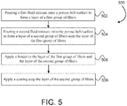
- a method of forming a multi-layer fiber mat includes pouring or discharging a first fluid mixture onto a porous belt or surface.
- the first fluid mixture includes a first fluid and a first group of fibers that are homogenously mixed or dispersed within the first fluid.
- the method also includes draining or removing the first fluid from the first fluid mixture as the first fluid mixture is poured or discharged onto the porous belt or surface in order to form a layer of the first group of fibers atop the porous belt or surface.
- the method further includes pouring or discharging a second fluid mixture onto the porous belt or surface atop the layer of the first group of fibers as the first fluid is drained or removed from the first fluid mixture.
- the second fluid mixture includes a second fluid and a second group of fibers that are homogenously mixed or dispersed within the second fluid.
- the method additionally includes draining or removing the second fluid from the second fluid mixture as the second fluid mixture is poured or discharged onto the porous belt or surface in order to form a layer of the second group of fibers atop the porous belt or surface and atop the layer of the first group of fibers so that the layer of the second group of fibers and the layer of the first group of fibers are simultaneously formed.
- the method additionally includes applying a binder to the layer of the first group of fibers and the layer of the second group of fibers in order to simultaneously bind the layer of the first group of fibers and the layer of the second group of fibers together and to bind the first group of fibers and the second group of fibers together.
- the second fluid mixture may be poured or discharged onto the porous belt or surface within 30 inches of where the first fluid mixture is poured or discharged onto the porous belt or surface. In other embodiments, the second fluid mixture may be poured or discharged onto the porous belt or surface within 12 inches or within 6 inches of where the first fluid mixture is poured or discharged onto the porous belt or surface.
- the binder may be the only binder that is applied to the first group of fibers and the second group of fibers.
- the multi-layer fiber mat does not include a binder concentration at an interface between the layer of the first group of fibers and the layer of the second group of fibers.
- the binder is typically homogenously or uniformly dispersed within the multi-layer fiber mat.
- the first group of fibers may consist of coarse glass fibers having an average fiber diameter of between 8 ⁇ m and 25 ⁇ m.
- the second group of fibers may consist of a combination of coarse glass fibers having an average fiber diameter of between 8 ⁇ m and 25 ⁇ m and glass microfibers having an average fiber diameter of between 0.5 ⁇ m and 6 ⁇ m.
- the method may additionally include applying a coating atop the layer of the second group of fibers. The coating may be applied atop the layer of the second group of fibers upon the second group of fibers filtering out a component of the binder so that the component remains on an exterior surface of the layer of the second group of fibers.
- the method may additionally include positioning the multi-layer fiber mat atop a construction board during formation of the construction board.
- the embodiments below disclose fiber mat facers that may be coupled with constructions boards, such as ceiling panels, drywall boards, polyisocyanurate foam boards, etc. to provide an aesthetically appealing look.
- the fiber mat facers discussed below include multiple layers of glass fibers made in a single step or process.
- the layers of the facers discussed below are not separately formed and then combined in a later stage or process (i.e., separately made and then bonded together). Rather, the layers are formed simultaneously, which results in a facer that functions as a single layer in terms of structure and integrity despite having different fiber compositions and layer densities. Accordingly, the facers discussed may be produced at lower cost and in less time.
- the facers discussed below may include a coating.
- the coating may be aesthetic or add desired properties to the construction board.
- the coating may provide a flat, gloss-free surface.
- the coating may also enable a non-directional visual appearance, meaning that the appearance does not depend on the angle in which the fiber mat facer is viewed.
- the coating may be a fire retardant coating, water repellent coating, washable coating, impact-resistant coating, scratch-resistant coating, soil resistant coating, or a combination thereof.
- One or more of the layers may include a blend of differently sized in diameter glass fibers.
- the differently sized glass fibers form layers of different densities within the facer.
- one or more layers may include both coarse and microfibers.
- some embodiments may include one or more layers of differently sized coarse fibers, differently sized microfibers, or a combination thereof.
- the coarse or larger diameter fibers may range in size between about 8 and about 25 ⁇ m, and small diameter fibers or microfibers may range in size between about 0.5 and 6 ⁇ m.
- the coarse or larger diameter fibers may range in size between about 8 and about 16 ⁇ m, and more commonly between about 11 and 16 ⁇ m.
- the small diameter fibers or microfibers may range in size between about 1 and 6 ⁇ m, and more commonly between 2 and 4 ⁇ m.
- the non-woven fiber mat facilitates bonding between the core material and the facer by absorbing the core material of the construction board.
- the more dense layer of the non-woven fiber mat e.g., layer with microfibers
- the non-woven fiber mat may form a construction board that is aesthetically pleasing and uniform in appearance.
- Conventional facers often employ a coating on the exterior surface that prevents bleed through of the core material and/or that masks any bleed through of the core material that occurs.
- the facers described herein are able to prevent bleed through of the core material without requiring the use of a coating on the exterior surface of the facer. Further, a coating on the exterior surface is not needed since bleed through of the core material will not be present or visible on the exterior surface of the facer.
- the larger diameter fibers may be about 13 ⁇ m diameter fibers and the microfibers may be about 3 ⁇ m in diameter.
- the facer includes at least one binder that bonds the large diameter fibers and microfibers together to form the fiber mat.
- the binder may be water repellant and/or include a water repellant additive such as a stearylated melamine water repellant.
- FIG. 1 is a cross-sectional view of a construction board 10 with a facer 12 (e.g., glass facer) and a core material 14.
- the core material 14 may be gypsum, magnesium oxide, polyisocyanurate, polystyrene, etc.
- the facer 12 includes multiple layers (e.g., 1, 2, 3, 4, 5, or more). These layers are formed in a single process, that is the layers are not produced in separate processes and then later combined.
- the facer 12 includes a first layer 16 and a second layer 18.
- the first layer 16 is a non-woven glass fiber mat formed using coarse fibers 20.
- coarse fibers in this application is understood to mean glass fibers having an average diameter between about 8 and 25 ⁇ m and an average length between about 1 ⁇ 4 inch and 2 inches. While the first layer 16 includes coarse fibers 20, the second layer 18 typically includes microfibers 22.
- microfibers is understood to mean glass fibers having an average diameter between about 0.5 and 6 ⁇ m with varying length.
- the coarse and microfibers may be fibers made from E glass, C glass, T glass, sodium borosilicate glass, A & S glasses, as well as from Basalt, mineral wool, slag fiber (which are included in the term glass), and mixtures thereof.
- the second layer 18 is formed out of a combination of coarse fibers 20 and microfibers 22.
- the coarse fibers and microfibers are typically homogenously dispersed or distributed throughout the second layer 18.
- the percentage of weight of the coarse fibers 20 and the microfibers 22 may vary.
- the percentage by weight of the coarse fibers 20 in the second layer 18 may vary between 60 and 99 percent, while the percentage by weight of the microfibers 22 may vary between 1 and 40 percent.
- the percentage by weight of the coarse fibers 20 in the second layer 18 may vary between 1 and 20 percent, while the percentage by weight of the microfibers 22 may vary between 80 and 99 percent, which would result in a mat that is substantially less porous.
- the coarse fibers 20 in the second layer 18 provide strength and integrity to the layer.
- the second layer 18 may be formed entirely of microfibers 22 having an average fiber diameter of between 0.5 and 6 ⁇ m.
- the second layer 18 may be formed from a single, relatively uniform, microfiber size or the second layer 18 may be formed from a combination of differently sized microfibers 22, which are typically homogenously dispersed or distributed throughout the second layer 18.
- the second layer 18 may be formed from a first type of microfibers 22 having an average diameter between 0.5 and 1 ⁇ m, which is then mixed with a second type of microfibers 22 having an average diameter between 3 and 6 ⁇ m.
- the weight percentages of the first and second types of microfibers 22 may vary in the second layer 18.
- the percentage by weight of the first type of microfiber 22 may vary between 5 and 50 percent while the second type of microfiber 22 may vary between 50 and 95 percent.
- the percentages of the first and second types of microfibers may be varied depending on an aesthetic attribute of the resulting layer 18. For example, if the layer 18 needs to be smooth, the layer 18 will contain a higher percentage of the first type of microfibers 22 having average diameters between 0.5 and 1 ⁇ m. If the purpose of the layer 18 is mainly to block the core material from passing through to the external surface, the layer 18 could include a blend of the first and second types of microfibers that is closure to a 50 - 50 (weight %) blend.
- the first layer 16 may be formed entirely of coarse fibers 20 having an average fiber diameter of between 8 and 25 ⁇ m, between 8 and 16 ⁇ m, and more commonly between 11 and 16 ⁇ m.
- the first layer 16 may include both coarse fibers 20 and microfibers 22, which are typically homogenously dispersed or distributed throughout the first layer 16.
- the percentage by weight of the coarse fibers 20 in the first layer 16 may vary between 75 and 99 percent, while the percentage by weight of the microfibers 22 may vary between 1 and 25 percent.
- the first layer 16 may be formed from a combination of differently sized coarse fibers 20, which are typically homogenously dispersed or distributed throughout the first layer 16.
- the first layer 16 may be formed from a first type of coarse fibers 20 having an average diameter between 8 and 11 ⁇ m, which is then mixed with a second type of coarse fibers 20 having a diameter between 12 and 25 ⁇ m.
- the facer 12 includes a binder that binds the respective fibers together in the first layer 16 and in the second layer 18 and that also bonds the first layer 16 and the second layer 18 together.
- the facer 12 includes a single binder that functions to both bind the fibers together in the respective layers and bond the respective layers together.
- the binder is typically homogenously or relatively evenly dispersed or distributed throughout the facer 12. Stated differently, the binder may be distributed homogenously within the first layer 16 and the second layer 18 and may also be homogenously distributed through the first and second layers 16, 18. Since the binder is relatively evenly distributed through the facer 12 in this manner, the facer 12 does not include a separate binder, or a layer of binder, at an interface between the first layer 16 and the second layer 18.
- first and second layers 16, 18 there is not a concentration of a binder at an interface or boundary between the first and second layers 16, 18 since the binder is evenly distributed through the facer 12. This even distribution of the binder results from the formation of the first and second layers 16, 18 in a single step.
- the fibers of the first and second layers 16, 18 are more integrated, intertwined, and intermeshed with one another at the interface or boundary of the layers due to the formation of the layers in a single step. This results in more gradual transition between the first and second layers 16, 18.
- the facer 12 may have a combined thickness 26 between about 0.1 and 1.5 mm. In some embodiments, the thickness of the facer 12 may be less than 20 percent of an overall thickness of the core 14. Although the facer 12 is illustrated on only a single side or face of the core 14, it should be realized that in other embodiments, the facer 12 may be positioned on both sides or faces of the core 14. In such instances, the first layer 16 is typically positioned directly adjacent the core 14 while the second layer 18 is positioned atop the first layer 16 as illustrated in FIG. 1 .
- the facer 12 includes first and second layers 16, 18 with different densities.
- the differences in densities may facilitate coupling of the facer 12 to the core material 14 while also block the core material 14 from passing through (i.e., bleeding through) the facer 12.
- the first and second layers have respective thicknesses 30, 32.
- the thickness 30 of the first layer 16 may be between 0.1 and 1 mm
- the thickness 32 of the second layer 18 may be between 0.1 and 0.5 mm.
- Each of these layers 16, 18 may also be defined as a percentage of the overall facer thickness 26.
- the first layer 16 may be between 30 and 95 percent of the overall facer thickness 26, and the second layer 18 may be between 5 and 50 percent of the overall facer thickness 26.
- the density of the second layer 18 may be proportional to the thickness of the second layer 18. For example, if the second layer 18 is more dense then the layer 18 may be thinner while still be effective to prevent bleed through. If the second layer 18 is too dense, however, the second layer 18 may not be open or porous enough to release moisture during curing, which might pose downstream issue during manufacturing of the board. The second layer 18 may be less dense when the layer 18 is a little thicker. The combination of the less dense and thicker board may still be effective to prevent bleed through. The combination of density and thickness described herein provides a good balance that is effective to prevent bleed through without causing manufacturing difficulties.
- the thickness 30 of the first layer 16 may be greater than the thickness 32 of the second layer 18 because the first layer 16 may include more coarse fibers 20. Furthermore, because the first layer 16 includes coarse fibers 20 the density of the first layer 16 may be less than the second layer 18. The use of the coarse fibers 20 in the first layer 16 may render the first layer 16 more porous than the second layer 18.
- the first layer 16 may have a Frasier air permeability of greater than or equal to 500 cubic feet per minute (cfm) when measured against a pressure drop of 0.5 in of water.
- the second layer 18 may have a Frasier air permeability of less than or equal to 300 cfm when measured according to the same standard.
- the general standard for measuring the Frasier air permeability is in accordance with ASTM D737-96.
- the less dense first layer 16 enables the first layer 16 to absorb the core material 14 when the facer 12 is applied as a facer to the core material 14 during manufacturing of the construction board 10.
- the core material 14 may be relatively wet or unhardened and may absorb or penetrate into the first layer 16 due to the porosity of the first layer 16. The penetration or absorption of the core material 14 into the first layer 16 may bind the core material 14 to the facer 12 during manufacturing.
- the second layer 18 includes microfibers 22 the second layer 18 is more dense than the first layer 16; the second layer 18 may therefore block the core material 14 from passing through the facer 12 when the facer 12 is applied as a facer to the core material 14 during manufacture of the construction board 10.
- the use of a significant amount of microfibers 22 in the second layer 18 renders the second layer 18 significantly less porous than the first layer 16, which blocks or prevents the core material 14 from bleeding through the second layer 18 to an exterior surface of the facer 12 where it would be visible.
- the inclusion of a significant amount of microfibers 22 in the second layer 18 allows the second layer 18 to exhibit a Frasier air permeability of less than or equal to 300 cfm.
- the core material 14 may absorb fully through the first layer 16 and partially through the second layer 18.
- FIG. 2 is a cross-sectional view of a construction board 50.
- the construction board 50 includes a facer 12 coupled to a core material 14.
- the core material 14 may similarly be gypsum, magnesium oxide, polyisocyanurate, polystyrene, etc.
- the facer 12 includes multiple layers (e.g., 1, 2, 3, 4, 5, or more) formed in a single process.
- the facer 12 includes a first layer 16, a second layer 18, and a coating 52.
- the first layer 16 is a non-woven glass fiber mat formed using one or more types of coarse fibers.
- the term "coarse fibers” in this application is understood to mean glass fibers having an average diameter between about 8 and 25 ⁇ m and an average length between about 1 ⁇ 4 inch and 2 inches.
- the second layer 18 includes one or more types of microfibers and in some embodiments may include a combination of microfibers and coarse fibers.
- microfibers is understood to mean glass fibers having an average diameter between about 0.5 and 6 ⁇ m with varying length.
- the coarse and microfibers may be fibers made from E glass, C glass, T glass, sodium borosilicate glass, A & S glasses, as well as from Basalt, mineral wool, slag fiber (which are included in the term glass), and mixtures thereof.
- the second layer 18 may be formed out of a combination of coarse fibers 20 and microfibers 22, which are typically homogenously dispersed or distributed throughout the second layer 18.
- the percentage by weight of the coarse fibers 20 in the second layer 18 may vary between 60 and 99 percent, while the percentage by weight of the microfibers 22 may vary between 1 and 40 percent.
- the percentage by weight of the coarse fibers 20 in the second layer 18 may vary between 1 and 20 percent, while the percentage by weight of the microfibers 22 may vary between 80 and 99 percent, which would result in a mat that is substantially less porous.
- the coarse fibers 20 in the second layer 18 provide strength and integrity to the layer.
- the second layer 18 may be formed from a combination of differently sized microfibers 22, which are typically homogenously dispersed or distributed throughout the second layer 18.
- the second layer 18 may be formed from a first type of microfibers 22 having an average diameter between 0.5 and 1 ⁇ m, which is then mixed with a second type of microfibers 22 having an average diameter between 3 and 6 ⁇ m.
- the weight percentages of the first and second types of microfibers 22 may also vary in the second layer 18.
- the percentage by weight of the first type of microfiber 22 may vary between 5 and 50 percent while the second type of microfiber 22 may vary between 50 and 95 percent.
- the percentages of the first and second types of microfibers may be varied depending on an aesthetic attribute of the resulting layer 18.
- the layer 18 will contain a higher percentage of the first type of microfibers 22 having average diameters between 0.5 and 1 ⁇ m. If the purpose of the layer 18 is mainly to block the core material from passing through to the external surface, the layer 18 could include a blend of the first and second types of microfibers that is closure to a 50 - 50 (weight %) blend.
- the first layer 16 may also include both coarse fibers 20 and microfibers 22, which are typically homogenously dispersed or distributed throughout the first layer 16.
- the percentage by weight of the coarse fibers 20 in the first layer 16 may vary between 75 and 99 percent, while the percentage by weight of the microfibers 22 may vary between 1 and 25 percent.
- the first layer 16 may be formed from a combination of differently sized coarse fibers 20, which are typically homogenously dispersed or distributed throughout the first layer 16.
- the first layer 16 may be formed from a first type of coarse fibers 20 having average diameters between 8 and 11 ⁇ m, which is then mixed with a second type of coarse fibers 20 having average diameters between 12 and 25 ⁇ m.
- the weight percentages of the first and second types of coarse fibers 20 may also vary in the first layer 16.
- the percentage by weight of the first type of coarse fibers may vary between 50 and 95 percent while the second type of coarse fibers may vary between 5 and 50 percent.
- the facer 12 includes a binder that binds the respective fibers together in the first layer 16 and in the second layer 18 and that also bonds the first layer 16 and the second layer 18 together.
- the facer 12 includes a single binder that functions to both bind the fibers together in the respective layers and bond the respective layers together.
- the binder is typically homogenously or relatively evenly dispersed or distributed throughout the facer 12. Stated differently, the binder may be distributed homogenously within the first layer 16 and the second layer 18 and may also be homogenously distributed through the first and second layers 16, 18. Since the binder is relatively evenly distributed through the facer 12 in this manner, the facer 12 does not include a separate binder, or a layer of binder, at an interface between the first layer 16 and the second layer 18.
- first and second layers 16, 18 there is not a concentration of a binder at an interface or boundary between the first and second layers 16, 18 since the binder is evenly distributed through the facer 12. This even distribution of the binder results from the formation of the first and second layers 16, 18 in a single step.
- the fibers of the first and second layers 16, 18 are more integrated, intertwined, and intermeshed with one another at the interface or boundary of the layers due to the formation of the layers in a single step. This results in more gradual transition between the first and second layers 16, 18.
- the construction board 50 includes a facer 12 with the coating 52.
- the coating 52 is applied to the second layer 18 to supplement or add additional properties to the first and second non-woven glass layers 16 and 18.
- the coating 52 may be a fire retardant coating, water repellent coating, washable coating, impact-resistant coating, scratch-resistant coating, soil resistant coating, or a combination thereof.
- the coating 52 may be simply for aesthetic purposes.
- the coating 52 may be a binder based material that is configured to remain atop the facer 12 rather than penetrate through the facer to bind the first and second layers, 16 and 18, together.
- the binder of the coating 52 may be a modified urea-formaldehyde binder that includes a filler, such as mica.
- the inclusion of the mica may enable the binder to remain atop the facer 12 and thereby form the coating 52.
- the binder may adhere the coating 52 to the top surface of the facer 12.
- the coating may include other materials as described herein, such as Aluminum Trihydrate (ATH), calcium carbonate, clay, vermiculite, wollastanite etc. or a combination of these.
- the facer 12 and coating 52 may have a combined thickness 26 between about 0.1 and 1.5 mm. In some embodiments, the thickness of the facer 12 may be less than 20 percent of an overall thickness of the core 14. Although the facer 12 is illustrated on only a single side or face of the core 14, it should be realized that in other embodiments, the facer 12 may be positioned on both sides or faces of the core 14. In such instances, the first layer 16 is typically positioned directly adjacent the core 14 while the second layer 18 is positioned atop the first layer 16 as illustrated in FIG. 2 . A coating 52 may be applied atop the second layer 18.
- the facer 12 includes first and second layers 16, 18 with respective thicknesss 30, 32.
- the thickness 30 of the first layer 16 may be between 0.1 and 1 mm, and the thickness 32 of the second layer 18 may be between 0.1 and 0.5 mm.
- the coating 52 also defines a thickness 54, which is typically less than or equal to about 0.2 mm.
- Each of these layers 16, 18, and 52 may also be defined as a percentage of the overall facer thickness 26.
- the first layer 16 may be between 30 and 95 percent of the overall facer thickness 26
- the second layer 18 may be between 5 and 50 percent of the overall facer thickness 26
- the coating 52 may be less than 15 percent of the overall facer thickness 26.
- the density of the second layer 18 may be proportional to the thickness of the second layer 18. For example, if the second layer 18 is more dense then the layer 18 may be thinner while still be effective to prevent bleed through. If the second layer 18 is too dense, however, the second layer 18 may not be open or porous enough to release moisture during curing, which might pose downstream issue during manufacturing of the board. The second layer 18 may be less dense when the layer 18 is a little thicker. The combination of the less dense and thicker board may still be effective to prevent bleed through. The combination of density and thickness described herein provides a good balance that is effective to prevent bleed through without causing manufacturing difficulties.
- the thickness 30 of the first layer 16 may be greater than the thickness 32 of the second layer 18 because the first layer 16 may include more coarse fibers 20. Furthermore, because the first layer 16 includes coarse fibers 20 the density of the first layer 16 may be less than the second layer 18.
- the first layer 16 may be significantly more porous than the second layer 18.
- the first layer 16 may have a Frasier air permeability of greater than or equal to 500 cubic feet per minute (cfm) when measured against a pressure drop of 0.5 in of water.
- the second layer 18 may have a Frasier air permeability of less than or equal to 300 cfm when measured according to the same standard.
- the less dense first layer 16 enables the first layer 16 to absorb and bind the core material 14 to the facer 12 during manufacturing.
- the second layer 18 includes microfibers 22 the second layer 18 is more dense and less porous than the first layer 16; the second layer 18 is therefore able to block the core material 14 from passing through the facer 12.
- the density of the second layer 18 may absorb but also block the coating 52 from passing through second layer 18.
- the second layer 18 may reduce the use of coating 52 on the facer 12 while still forming a uniform and aesthetically appealing construction board 50.
- the core material 14 may absorb fully through the first layer 16 and partially through the second layer 18.
- the inclusion of a significant amount of microfibers 22 in the second layer 18 allows the second layer 18 to exhibit an Frasier air permeability of less than or equal to 300 cfm.
- the top layer i.e., second layer 18
- the top layer includes a combination of coarse fiber (3/4" K117 fibers are chopped glass fibers having an average fiber diameter of 13 ⁇ m and a length of 0.75 inch, commercially available from John Manville) and microfiber (110X-481; glass microfiber fibers having an average fiber diameter of 2.7, commercially available from John Manville).
- the top layer includes approximately 90% coarse fibers and 10% microfibers.
- the bottom layer i.e., second layer 18 includes a combination of coarse fiber (3/4" K117 fibers) and microfiber (110X-481).
- the binder is a modified urea-formaldehyde (UF) binder.
- a filler material i.e., mica
- the mica that was added to the binder formed a coating (i.e., coating 52) atop the facer.
- the binder also adhered the filler particles (mica) together and adhered the coating layer to the facer.
- Example 2 is similar to example 1 with the primary difference being the type of filler material that was employed.
- the filler material is Aluminum Trihydrate (ATH).
- the filler material (ATH) formed a layer atop the facer due to the filler material being filter out by the second layer.
- the air permeability may be controlled by the amount and type of filler particles that are added to the binder.
- the binder was added so that the facer exhibited a loss on ignition of approximately 27-28%.
- the properties of both facers were roughly the same with the exception of the air permeability, which was significantly less in the facer of example 1 due to the coating of the mica.
- the Frasier air permeability in example 1 was significantly less despite the facers having a roughly equivalent mean pore size.
- the first conventional mat i.e., labeled "Mat 1" in Table 2
- the porosity of Mat 1 is in the mid-range, which may be attributed to the addition of microfiber.
- Table 3 demonstrates that Mat 1 has a high propensity to absorb water (i.e., 292% weight absorption), which might not be desirable for certain applications.
- the absorption percentage indicated in Table 3 is the weight of water absorbed by the glass mat as a percentage of the mat weight.
- Mat 1 it may be possible to reduce the water absorption by adding a coating layer to Mat 1, however, for certain applications the addition of a coating may render Mat 1 too closed off (indicated by low air perm of 280) to allow the core material to penetrate into the mat, which would result in a weak bond between the core material and Mat 1.
- the other conventional mat i.e., labeled "Mat 2" in Table 2
- Mat 2 is too open or porous as demonstrated by the high air permeability and thus, Mat 2 suffers from the core material bleeding through the mat to the exterior surface of the facer.
- a coating layer typically cannot be applied to Mat 2 as described herein due in part to the high air permeability since the high porosity of the mat will allow the coating to penetrate into and throughout the mat, which will close off the pores. The closed pores prevent the core material from penetrating into the mat, which would result in a weak bond between the core material and the facer.
- a coating layer has to be applied as a secondary and separate step, which is a time consuming, complicated, and costly process.
- conventional Mat 1 can be combined with conventional Mat 2 to form a dual layer.
- this combination has to be performed in a second step by application of a binder/adhesive at the interface of the two mats.
- the application of the adhesive at the interface results in a concentration of binding material at the interface of the two layers and further results in two distinct layers - i.e., one layer containing the coarse fiber and microfiber and the other layer being solely coarse fiber.
- Example 1 in Table 2 is a dual layer structure where top layer consists of 3 ⁇ 4 inch Johns Manville K117 glass fiber and Johns Manville 110X-481 glass microfiber.
- the bottom layer is 100 percent 3 ⁇ 4 inch Johns Manville K117 glass fibers. Both layers are formed simultaneously as described herein and thus, the resulting mat is free of a concentrated adhesive layer between the two layers.
- the binder is modified UF, which binds the fibers and the two layers together. Mica was added to the binder which forms a top coating layer.
- the bottom layer is open and has an air permeability similar to Mat 2 (i.e., 617 cfm), which allows the core material to penetrate into the bottom layer and form a good bond.
- the top layer has an air permeability similar to Mat 1 (i.e., 280), which prevents bleed through of the core material.
- the mica coating on top can provide additional smoothness to the facer for handling, for reducing water absorption, for reducing air permeability and/or porosity, etc.
- Example 1 may have a total air permeability of about 139 cfm.
- Example 2 in Table 2 is constructed similar to that of Example 1, except that ATH was added to the binder instead of Mica.
- Example 2 demonstrates that different raw materials can be used as a coating layer.
- Table 3 shows a comparison of the mat produced in Example 2 and Mat 1 and specifically shows a significant reduction in water absorption that is achieved via the mat of Example 2 - i.e., 3.70 percent in comparison with 292 percent for Mat 1.
- Example 3 in Table 2 is constructed similar to that of Examples 1 and 2.
- the binder used in Example 3 is an acrylic binder modified with UF, which demonstrates that various examples of binders can be used to construct the multilayered mats described herein. No filler was added to the binder used in constructing the mat of Example 3.
- the single binder is the only component that is used to bond or adhere the fibers in the two layers and to bond or adhere the two layers together.
- the binder is uniformly or homogenously distributed throughout the top and bottom layers and there is no binder concentration at the interface.
- a small gradient of microfibers exists at the interface, which enhances the physical bond or entanglement of the fibers of the top and bottom layers.
- a portion of the microfibers of the second layer 18 at or near the interface migrate into the first layer 16 and vice versa.
- the degree of migration of the fibers and the resulting physical bond or entanglement is unique to the mats formed in accordance with the disclosure herein since such entanglement and migration is not achievable without simultaneously forming the layers.
- Table 3 shows a comparison between conventional Mat 1 and the mat of Example 2 in Table 2 above.
- Table 3 Comparison of conventional Mat 1 and Example mat 2 of Table 2 Fiber Binder Absorption Mat 1 90% 3/4" K117 & 10% 110x-481 Arclin UF + Dow Acrylic 292%
- Top layer 90% 3/4" K117 & 10% 110X-481 Arclin UF + Dow Acrylic & ATH 3.70%
- Bottom Layer 100% 3/4" K117
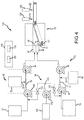
- FIG. 3 is a schematic view of a manufacturing system 68 that produces a facer 12.
- the manufacturing system 68 is able to produce a multilayered facer in a single step/process. That is the layers of the facer are not separately formed and then combined at a later stage or process (i.e., separately made and then bonded together).
- the facers 12 produced by the manufacturing system 68 may therefore be produced at lower cost and in less time.
- the manufacturing system 68 includes multiple fluid lines that deliver coarse fibers and microfibers to a hydroformer 70 that simultaneously forms the first and second layers 16, 18 of the facer 12. While a hydroformer 70 is illustrated, a fourdinier wire or a delta former may also be used to produce first and second layers 16, 18 of the facer 12 in a single step/process.
- the manufacturing system 68 produces the first layer 16 using a first fluid line 72 that delivers coarse fiber to the hydroformer.
- the first fluid line 72 includes at least one coarse fiber source 74 containing one or more types of coarse fibers (e.g., differently sized coarse fibers, coarse fibers made from different materials, or a combination thereof).
- Fluidly coupled to the coarse fiber source 74 is a pump 76 (e.g., a thick stock pump) that pumps a first fluid 77 containing the coarse fibers.
- the first fluid 77 may include water, viscosity modifiers, dispersants, defoamers, etc. mixed with the coarse fibers.
- the first fluid 77 is diluted with a dilution fluid 78 (e.g., water, viscosity modifiers, dispersants, defoamers, or a combination thereof) stored in a dilution tank 80.
- a dilution fluid 78 e.g., water, viscosity modifiers, dispersants, defoamers, or a combination thereof
- the dilution fluid 80 combines with the first fluid 77 before the first fluid 77 enters a second pump 82.
- the pump 82 e.g., thin stock pump
- the first fluid 77 After exiting the pump 82, the first fluid 77 enters a first inlet pipe 84 of the hydroformer 70.
- the first inlet pipe 84 directs the first fluid 77 into the hydroformer 70, which forms the first layer of the facer 12 by removing the first fluid 77 and dilution fluid 80 from the fluid/coarse fiber mixture as the mixture is poured onto the hydroformer 70.
- the manufacturing system 68 includes a second fluid line 86.
- the second fluid line 86 includes at least one coarse fiber source 74 containing one or more types of coarse fibers (e.g., differently sized coarse fibers, coarse fibers made from different materials, or a combination thereof).
- Fluidly coupled to the coarse fiber source 74 is a pump 88 (e.g., a thick stock pump) that pumps a second fluid 89 containing the coarse fibers.
- the second fluid 89 may include water, viscosity modifiers, dispersants, defoamers, etc. mixed with the coarse fibers.
- the second fluid 89 is diluted with a dilution fluid 90 (e.g., water, viscosity modifiers, dispersants, defoamers, or a combination thereof) stored in a dilution tank 92.
- a dilution fluid 90 e.g., water, viscosity modifiers, dispersants, defoamers, or a combination thereof
- the dilution fluid 90 combines with the second fluid 89 before the second fluid 89 enters a second pump 94.
- the pump 94 e.g., thin stock pump
- the second fluid 89 enters a second inlet pipe 96 of the hydroformer 70.
- the second inlet pipe 96 directs the second fluid 89 into the hydroformer 70, which forms the second layer 18 of the facer 12 by removing the second fluid 89 and dilution fluid 90 from the fluid/fiber mixture as the mixture is poured onto the hydroformer 70 atop the first layer of the facer 12 that was immediately formed by the hydroformer.
- the second fluid 89 is directed or poured atop the first layer of the facer 12 as the fluid is being drained from the first fluid 77 such that the second layer 18 and the first layer 16 are formed simultaneously by the hydroformer.
- the third fluid line 98 includes at least one microfiber source 100 containing one or more types of microfibers (e.g., differently sized microfibers, microfibers made from different materials, or a combination thereof).
- Fluidly coupled to the microfiber source 100 is a pump 102 (e.g., a stock pump) that pumps a third fluid 103 containing the microfibers.
- the third fluid 103 may include water, viscosity modifiers, dispersants, defoamers, etc. mixed with the microfibers. After passing through the pump 102, the third fluid 103 may be pumped into the first and/or second fluid lines 72, 86.
- the third fluid line 98 couples upstream from the pumps 76 and 88.
- the manufacturing system 68 uses the turbulent flow through the pumps 76 and 88 to facilitate mixing of the third fluid 103 with the first and/or second fluids 77, 89.
- the third fluid line 98 may couple to the first and second fluid lines 72, 86 downstream from the pumps 76 and 88.
- the manufacturing system 68 may rely on the pumps 82 and 94 to mix the third fluid 103 with the first or second fluids 77, 89.
- the third fluid line 98 may couple upstream as well as downstream of the pumps 76 and 88. This layout may enable the gradual introduction of the third fluid into the first and/or second fluid lines at different locations.
- the flow of the first, second, and third fluids 77, 89, 103 through the manufacturing system 68 may be controlled with a controller 104.
- the controller 104 may include one or more processors 106 that execute instructions stored on one or more memories 108 to control the operation of various valves as well as the pumps.
- the third fluid line 98 may include first and second valves 110, 112.
- the first valve 110 controls the flow of the third fluid into the first fluid line 72
- the second valve 112 controls the flow of the third fluid into the second fluid line 86.
- the controller 104 is able to control the amount of the third fluid combining with the first and/or second fluids 77, 89.
- the manufacturing system 68 may vary the microfiber content in the first and second layers 16, 18 to between 0 and 100 percent, and more commonly to the percentages described in the facer embodiments herein.
- the manufacturing system 68 may also control the fluid flow through the first and second fluid lines 72, 86 using additional valves 114 and 116 as well as controlling the pumps 76, 82, 88, 94, and 102. By controlling the flow of the first and second fluids 77, 89 the controller 104 may increase or decrease thickness of the respective first and second layers 16, 18. Stated differently, the manufacturing system 68 may increase or decrease the thickness of the first and/or second layers 16, 18 of the facer 12 depending on the type of desired facer 12. For example, the manufacturing system 68 may increase the flow of the first fluid 77 through the fluid line 72 to increase the thickness of the first layer 16 and decrease the flow of the second fluid 89 to decrease the thickness of the second layer 18. Similarly, the manufacturing system 68 may decrease the flow of the first fluid 77 through the fluid line 72 to decrease the thickness of the first layer 16 and increase the flow of the second fluid 89 to increase the thickness of the second layer 18.
- first and second fluids 77, 89 enter the hydroformer 70 they contact a conveyer belt 117 that drains a substantially majority of the fluid in the first and second fluids 77, 89 leaving behind the combined first and second layers 16, 18.
- the manufacturing system 68 may then apply one or more binders 118.
- the binder 118 may include additives, such as flame resistant resinous binders such as urea formaldehyde, modified urea formaldehyde, acrylic resins, modified acrylic resins, polyurethanes, polyvinyl chlorides, melamine resins, homopolymers or copolymers of polyacrylic acid; crosslinking acrylic copolymers; crosslinked vinyl chloride acrylate copolymers (e.g., copolymers having a GTT of about 113°C or less), among other types of binders.
- Flame retardants may also be included in the binder, such as Alumina trihydrate, organic phosphonates, Antimony oxide, and the like.
- binders 118 may be stored in one or more binder sources 120.
- the binder(s) 118 may be applied to the first and second layers 16, 18 by moving the first and second layers 16, 18 under a spray or waterfall of binder. Any excess binder may then flow through the first and second layers.
- the manufacturing system 68 may bind the fibers in their respective layers as well as bind the layers 16, 18 together without performing multiple binding steps/processes. Stated differently, the manufacturing system 68 may simultaneously bind the fibers in the respective layers and bond the fibers layers together in a single step.
- the application of the binder(s) 118 to the first and second layers 16, 18 simultaneously results in the binder being relatively evenly distributed through and between the first and second layers 16, 18 without forming or defining a binder layer between the first and second layers 16, 18.
- a separate or individual layer of binder is not formed or defined at an interface or boundary between the first and second layers 16, 18 as occurs in conventional systems where the layers are formed individually and combined in a subsequent process.
- the relatively even distribution of the binder(s) 118 may increase the strength of the facer and/or reduce issues such as delamination of the layers.
- the facer described herein has a less defined boundary between the first and second layers 16, 18 since these layers are simultaneously formed. Rather, the facer has a relatively gradual transition from the first layer 16 to the second layer 18 due to the simultaneous formation of the layers, which may increase the strength and/or reduce issues such as delamination of the layers.
- the manufacturing system 68 may deposit a coating(s) 122 atop the second layer 18 after applying the binder 118.
- the coating 122 may be stored in a coating source 124 (e.g., tank) and sprayed onto the facer 12.
- the coating may be formed via a filler material that is added to the binder and that is filtered out via the second layer 18.
- the filler material e.g., mica
- the binder may be applied to the facer 12 to bind the fibers together.
- Excess binder 118 may be removed from the facer 12 via an applied vacuum or via some other method.
- the second layer 18, and in particular the microfibers, may act as a filter for the filler material (e.g., mica) during the binder application process.
- the filler material that is deposited on and remains atop the second layer 18 forms a coating layer 122.
- the binder 118 adheres the filler particle to the second layer 18, thereby adhereing the coating 122 to the second layer 18.
- a second or additional step of applying the coating 122 separately is not needed.
- the coating 122 may be a fire retardant coating, water repellent coating, washable coating, impact-resistant coating, scratch-resistant coating, soil resistant coating, or a combination thereof.
- FIG. 4 is a schematic view of a manufacturing system 140 that produces a facer 12.
- the manufacturing system 140 is able to produce a multilayered facer in a single step/process. That is the layers 16, 18 of the facer 12 are not separately formed and then combined at a later stage or process (i.e., separately made and then bonded together).
- the facers 12 produced by the manufacturing system 140 may therefore be produced at lower cost and in less time.
- the manufacturing system 140 includes multiple fluid lines that deliver coarse fibers and microfibers to a hydroformer 70 that simultaneously forms the first and second layers 16, 18 of the facer 12. While a hydroformer 70 is illustrated, a fourdinier wire or delta former may also be used to produce first and second layers 16, 18 of the facer 12 in a single step/process.
- the manufacturing system 140 produces the first layer 16 using a first fluid line 72 that delivers coarse fiber to the hydroformer.
- the first fluid line 72 includes at least one coarse fiber source 74 containing one or more types of coarse fibers (e.g., differently sized coarse fibers, coarse fibers made from different materials, or a combination thereof).
- Fluidly coupled to the coarse fiber source 74 is a pump 76 (e.g., a thick stock pump) that pumps a first fluid 77 containing the coarse fibers.
- the first fluid 77 may include water, viscosity modifiers, dispersants, defoamers, etc. mixed with the coarse fibers.
- the first fluid 77 is diluted with a dilution fluid 78 (e.g., water, viscosity modifiers, dispersants, defoamers, or a combination thereof) stored in a dilution tank 80.
- a dilution fluid 78 e.g., water, viscosity modifiers, dispersants, defoamers, or a combination thereof
- the dilution fluid 80 combines with the first fluid 77 before the first fluid 77 enters a second pump 82.
- the pump 82 e.g., thin stock pump
- the first fluid 77 After exiting the pump 82, the first fluid 77 enters a first inlet pipe 84 of the hydroformer 70.
- the first inlet pipe 84 directs the first fluid 77 into the hydroformer 70, which forms the first layer of the facer 12 by removing the first fluid 77 and dilution fluid 80 from the fluid/fiber mixture as the mixture is poured onto the hydroformer 70.
- the manufacturing system 140 includes a second fluid line 86.
- the second fluid line 86 includes at least one coarse fiber source 87 containing one or more types of coarse fibers (e.g., differently sized coarse fibers, coarse fibers made from different materials, or a combination thereof).
- the coarse fibers in the coarse fiber source 87 may be the same as or different from the coarse fibers in the coarse fiber source 74.
- the first and second fluid lines 72 and 86 may produce layers with different coarse fibers sizes and/or coarse fibers made from different materials.
- Fluidly coupled to the coarse fiber source 74 is a pump 88 (e.g., a thick stock pump) that pumps a second fluid 89 containing the coarse fibers.
- the second fluid 89 may include water, viscosity modifiers, dispersants, defoamers, etc. mixed with the coarse fibers.
- the second fluid 89 is diluted with a dilution fluid 90 (e.g., water, viscosity modifiers, dispersants, defoamers, or a combination thereof) stored in a dilution tank 92.
- a dilution fluid 90 e.g., water, viscosity modifiers, dispersants, defoamers, or a combination thereof
- the dilution fluid 90 combines with the second fluid 89 before the second fluid 89 enters a second pump 94.
- the pump 94 (e.g., thin stock pump) enables mixing of the second fluid 89 and the dilution fluid 90 before delivery to the hydroformer 70.
- the second fluid 89 enters a second inlet pipe 96 of the hydroformer 70.
- the second inlet pipe 96 directs the second fluid 89 into the hydroformer 70, which forms the second layer 18 of the facer 12 by removing the second fluid 89 and dilution fluid 90 from the fluid/fiber mixture as the mixture is poured onto the hydroformer 70 atop the first layer of the facer 12 that was immediately formed by the hydroformer.
- the second fluid 89 is directed or poured atop the first layer 16 of the facer 12 as the fluid is being drained from the first fluid 77 such that the second layer 18 and the first layer 16 are formed simultaneously by the hydroformer.
- the third fluid line 98 includes at least one microfiber source 100 containing one or more types of microfibers (e.g., differently sized microfibers, microfibers made from different materials, or a combination thereof).
- Fluidly coupled to the microfiber source 100 is a pump 102 (e.g., a stock pump) that pumps a third fluid 103 containing the microfibers.
- the third fluid 103 may include water, viscosity modifiers, dispersants, defoamers, etc. mixed with the microfibers. After passing through the pump 102, the third fluid 103 may be pumped into the first and/or second fluid lines 72, 86.
- the third fluid line 98 couples upstream from the pumps 76 and 88.
- the manufacturing system 140 uses the turbulent flow through the pumps 76 and 88 to facilitate mixing of the third fluid 103 with first and/or second fluids 77, 89.
- the third fluid line 98 may couple to the first and second fluid lines 72, 86 downstream from the pumps 76 and 88.
- the manufacturing system 68 may rely on the pumps 82 and 94 to mix the third fluid 103 with the first or second fluids 77, 89.
- the third fluid line 98 may couple upstream as well as downstream of the pumps 76 and 88. This layout may enable the gradual introduction of the third fluid into the first and/or second fluid lines at different locations.
- the flow of the first, second, and third fluids 77, 89, 103 through the manufacturing system 140 may be controlled with a controller 104.
- the controller 104 may include one or more processors 106 that execute instructions stored on one or more memories 108 to control the operation of the valves as well as the pumps.
- the third fluid line 98 may include first and second valves 110, 112.
- the first valve 110 controls the flow of the third fluid into the first fluid line 72
- the second valve 112 controls the flow of the third fluid into the second fluid line 86.
- the controller 104 is able to control the amount of the third fluid combining with the first and/or second fluids 77, 89. This in turn controls the amount of microfibers in the first and second layers 16, 18.
- the first and second layers 16, 18 may vary in microfiber content including having no microfiber content.
- the manufacturing system 140 may also control the fluid flow through the first and second fluid lines 72, 86 by controlling the pumps 76, 82, 88, 94, and 102. By controlling the flow of the first and second fluids 77, 89 the controller 104 may increase or decrease thickness of the respective first and second layers 16, 18. That is the manufacturing system 140 may increase or decrease the thickness of the first and/or second layers 16, 18 of the facer 12 depending on the desired facer 12. For example, a specific application may call for a thicker facer 12 to absorb more core material during manufacturing of the construction board 10.
- first and second fluids 77, 89 enter the hydroformer 70 they contact a conveyer belt 117 that drains a substantially majority of the first and second fluids 77, 79 leaving behind the combined first and second layers 16, 18.
- the manufacturing system 140 may then apply one or more binders 118.
- the binder 118 may include additives, such as flame resistant resinous binders such as urea formaldehyde, modified urea formaldehyde, acrylic resins, modified acrylic resins, polyurethanes, polyvinyl chlorides, melamine resins, homopolymers or copolymers of polyacrylic acid; crosslinking acrylic copolymers (e.g., acrylic copolymers having a glass transition temperature (GTT) of at least about 25°C); crosslinked vinyl chloride acrylate copolymers (e.g., copolymers having a GTT of about 113°C or less), among other types of binders.
- Flame retardants may also be included in the binder, such as Alumina trihydrate, organic phosphonates, Antimony oxide, and the like.
- binders 118 may be stored in one or more binder sources 120.
- the binder(s) 118 may be applied to the first and second layers 16, 18 by moving the first and second layers 16, 18 under a spray or waterfall of binder. Any excess binder 118 may then flow through the first and second layers.
- the manufacturing system 140 may bind the fibers in their respective layers as well as bond the layers 16, 18 together without performing multiple binding steps/processes. Stated differently, the manufacturing system 140 may simultaneously bind the fibers in the respective layers and bond the fibers layers together in a single step.
- a separate or individual layer of binder is not formed or defined at an interface or boundary between the first and second layers 16, 18 as occurs in conventional systems where the layers are formed individually and combined in a subsequent process.
- the relatively even distribution of the binder(s) 118 may increase the strength of the facer and/or reduce issues such as delamination of the layers.
- the facer has a less defined boundary between the first and second layers 16, 18 since these layers are simultaneously formed. Rather, the facer has a relatively gradual transition from the first layer 16 to the second layer 18 due to the simultaneous formation of the layers, which may increase the strength and/or reduce issues such as delamination of the layers.
- the manufacturing system 140 may deposit a coating(s) 122 on the second layer 18.
- the coating 122 may be stored in a coating source 124 (e.g., tank) and sprayed onto the facer 12.
- the coating may be formed via a filler material that is added to the binder and that is filtered out via the second layer 18.
- the filler material e.g., mica
- the binder may be applied to the facer 12 to bind the fibers together.
- Excess binder 118 may be removed from the facer 12 via an applied vacuum or via some other method.
- the second layer 18, and in particular the microfibers, may act as a filter for the filler material (e.g., mica) during the binder application process.
- the filler material that is deposited on and remains atop the second layer 18 forms a coating layer 122.
- the binder 118 adheres the filler particle to the second layer 18, thereby adhereing the coating 122 to the second layer 18.
- a second or additional step of applying the coating 122 separately is not needed.
- the coating 122 may be a fire retardant coating, water repellent coating, washable coating, impact-resistant coating, scratch-resistant coating, soil resistant coating, or a combination thereof.
- the fibers were referred to a glass fibers - i.e., coarse glass fibers, microfibers, and the like. It should be realized that various other fiber types may be used in any of the embodiments described herein and that the embodiments are not limited solely to glass fibers unless otherwise specified in the claims. It should also be realized that the use of non-glass fibers are contemplated as being used in any of the embodiments. The non-glass fibers may be used in combination with glass fibers or instead of glass fibers. Accordingly, unless otherwise explicitly specified in the claims, the concepts and embodiments described herein may include only glass fibers, only non-glass fibers, or any combination of glass and non-glass fibers.
- non-glass fibers include polymer fibers, synthetic fibers, organic fibers, inorganic fibers, natural fibers, and the like.
- glass microfibers and/or glass coarse fibers described herein can be partially or completely replaced with polymeric, synthetic, or natural microfibers.
- fibers may be used in the claims with such usage being understood to cover a variety of fibers including glass fibers and non-glass fibers.
- coarse fibers and microfibers will be understood in relation to size to have the definitions provided herein.
- the fiber mat may be a glass facer for a construction board.
- a first fluid mixture is poured or applied onto a porous belt or surface.
- the first fluid mixture includes a first group of fibers that are homogenously mixed or dispersed within a first fluid.
- the first group of fibers comprise or consist of coarse glass fibers having an average fiber diameter of between 8 ⁇ m and 25 ⁇ m.
- the first group of fibers comprise or consist of a combination of coarse fibers and microfibers as described herein.
- the first fluid mixture When the first fluid mixture is applied or poured atop the porous belt or surface, the first fluid is drained or removed from the first fluid mixture so that a layer of the first group of fibers is formed atop the porous belt or surface.
- a vacuum may be applied to the porous belt or surface to facilitate in removal of the first fluid from the first fluid mixture.
- a second fluid mixture is poured or applied onto the porous belt or surface atop the layer of the first group of fibers.
- the second fluid mixture includes a second group of fibers that are homogenously mixed or dispersed within a second fluid.
- the second group of fibers comprise or consist of a combination of coarse glass fibers having an average fiber diameter of between 8 ⁇ m and 25 ⁇ m and glass microfibers having an average fiber diameter of between 0.5 ⁇ m and 6 ⁇ m.
- the amount of each fiber type may be similar to the embodiments described herein.
- the second group of fibers comprises or consists entirely of glass microfibers having an average fiber diameter of between 0.5 ⁇ m and 6 ⁇ m.
- the second fluid mixture When the second fluid mixture is applied or poured atop the porous belt or surface, the second fluid is drained or removed from the second fluid mixture so that a layer of the second group of fibers is formed atop the porous belt or surface and atop the layer of the first group of fibers.
- the second fluid mixture is poured or applied onto the porous belt or surface as the first fluid is being removed from the first fluid mixture.
- the layer of the first group of fibers is typically not fully formed or defined until after the second fluid mixture is poured or applied onto the porous belt or surface. In this manner, the layer of the first group of fibers and the layer of the second group of fibers are formed simultaneously atop the porous belt or surface.
- the second fluid mixture may be poured directly vertically above the first fluid layer and thus, both layers may be poured simultaneously atop each other.
- the layer of the first group of fibers is not fully formed or defined until after the second fluid mixture is poured or applied onto the porous belt or surface, the layer of the first group of fibers is formed or defined at essentially the same time as the layer of the second group of fibers is formed or defined atop of the porous belt or surface. Since the layer of the first group of fibers and the layer of the second group of fibers are formed simultaneously, the degree of intermeshing or entangling of the fibers at the interface of the two layers is significantly greater than in conventional fiber mats where one or both of the layers are fully formed or defined prior to application of the other layer.
- the second fluid mixture may be poured or applied onto the porous belt or surface within 30 inches of where the first fluid mixture is poured or applied onto the porous belt or surface.
- the fiber mat forming section i.e., porous belt
- the second layer may be poured within 12 inches or within 6 inches after the first layer is poured or applied to the porous belt.
- the first layer may be partially dewatered, but still in the process of forming on the porous belt.
- the second layer 18 (e.g., a more dense layer) may be poured atop the porous belt first and then the first layer 16 (e.g., a less dense layer) may be poured atop the second layer 18.
- the first layer 16 e.g., a less dense layer
- a more dense layer may be formed on the bottom while a less dense layer is simultaneously formed on the top.
- a binder is simultaneously applied to the layer of the first group of fibers and the layer of the second group of fibers in order to bind the two layers together and to bind the various fibers within each layer together.
- a binder is not applied to either layer prior to block 506, or stated differently, the layers are typically free of a binder prior to block 506.
- the simultaneous application of the binder to the two layers, which are typically free of a binder prior to block 506, results in a more homogenous or uniform distribution of the binder throughout the fiber mat.
- the simultaneous application of the binder to the two layer results in the fiber mat being free of a concentrated binder layer at the interface of the two layers.
- Conventional fiber mats typically include a binder concentration at the interface between layers because the fiber layers are formed separately and then adhered or bonded together via an additional binder.
- the additional binder bonds the two layers together and is typically concentrated at the interface between the two layers.
- the process described herein is able for form a multiple layer fiber mat construction in which the binder is relatively homogenously or uniformly dispersed throughout the mat rather than being concentrated in one or more areas.
- a single binder may be employed to both bond or adhere the layers together and bond or adhere the fibers of the various layers together.
- Conventional mats commonly require the use of multiple binders in order to bond the fibers of the separate layers together and to subsequently bond the layers together.
- a coating may optionally be applied atop the layer of the second group of fibers.
- the coating may be applied via a process that is separate from the application of the binder or the coating may be formed during the binder application process.
- the binder may include a component (e.g., mica) that is filtered out by the layer of the second group of fibers as the binder is applied to this layer.
- the component that is filtered out may remain atop or on the exterior surface of the layer of the second group of fibers and form the coating.
- the applied binder may bond or adhere the coating to the layer of the second group of fibers.
- a separate coating may be applied to the layer of the second group of fibers subsequent to the application of the binder.
- the applied binder may bond or adhere the coating to the layer of the second group of fibers or an additional binder may be used to bond or adhere the coating to the layer of the second group of fibers.
- the coating may be a water resistant coating, a fire-resistant coating, and an abuse-resistant coating, and the like.
- the fiber mat that is formed according to the method 500 of FIG. 5 may be a facer for a construction board.
- the facer may be applied to the construction board during formation of the construction board.
- the layer of the first group of fibers may be capable of absorbing a material of the construction board when the facer is positioned atop the construction board during formation of the construction board.
- the layer of the second group of fibers may partially absorb the material of the construction board, but may block the material from passing or absorbing through the facer to an exterior surface of the second layer.
- the facer may be adhered or bonded with the construction board due to the absorption of the construction board material within the facer, but the material may not be visible on the exterior surface and, therefore, the visual appeal of the facer may be improved.
- the ability of the facer to block the construction board material from passing or absorbing through the facer to an exterior surface of the second layer is enabled without the use of a coating on the exterior surface of the second layer. As such, a coating is not required to visibly conceal the construction board's material from view, although a coating may be applied to add further visual appeal to the facer as desired.
- the ability of the second layer to block the construction board's material from passing or absorbing through the facer is due to the decreased porosity or air permeability of the second layer in comparison with the first layer as described herein.
- the method 500 of FIG. 5 is described as simultaneously forming two layers, the method 500 could be employed to simultaneously form three or more layers as described.
- block 504 could be repeated with a third fluid mixture, a fourth fluid mixture, and the like to form additional layers atop the layer of the second group of fibers.
- the binder could then be simultaneously applied to each of the layers at block 506 as desired.
- the method 500 of FIG. 5 is not limited to two layer constructions.
Landscapes
- Engineering & Computer Science (AREA)
- Life Sciences & Earth Sciences (AREA)
- Wood Science & Technology (AREA)
- Structural Engineering (AREA)
- Architecture (AREA)
- Chemical & Material Sciences (AREA)
- Composite Materials (AREA)
- Mechanical Engineering (AREA)
- Textile Engineering (AREA)
- Civil Engineering (AREA)
- Laminated Bodies (AREA)
- Finishing Walls (AREA)
- Building Environments (AREA)
Priority Applications (1)
| Application Number | Priority Date | Filing Date | Title |
|---|---|---|---|
| PL18178520T PL3428362T3 (pl) | 2017-06-19 | 2018-06-19 | Okładzina wielowarstwowa |
Applications Claiming Priority (1)
| Application Number | Priority Date | Filing Date | Title |
|---|---|---|---|
| US15/626,495 US10569508B2 (en) | 2017-06-19 | 2017-06-19 | Multilayer facer |
Publications (3)
| Publication Number | Publication Date |
|---|---|
| EP3428362A2 EP3428362A2 (en) | 2019-01-16 |
| EP3428362A3 EP3428362A3 (en) | 2019-03-20 |
| EP3428362B1 true EP3428362B1 (en) | 2021-08-04 |
Family
ID=62778696
Family Applications (1)
| Application Number | Title | Priority Date | Filing Date |
|---|---|---|---|
| EP18178520.5A Active EP3428362B1 (en) | 2017-06-19 | 2018-06-19 | Multilayer facer |
Country Status (3)
| Country | Link |
|---|---|
| US (3) | US10569508B2 (pl) |
| EP (1) | EP3428362B1 (pl) |
| PL (1) | PL3428362T3 (pl) |
Families Citing this family (9)
| Publication number | Priority date | Publication date | Assignee | Title |
|---|---|---|---|---|
| AU2017362250B2 (en) * | 2016-11-15 | 2022-07-28 | Shaw Industries Group, Inc. | Layered composite articles and methods of making same |
| US10569508B2 (en) | 2017-06-19 | 2020-02-25 | Johns Manville | Multilayer facer |
| US20210299999A1 (en) * | 2020-03-31 | 2021-09-30 | United States Gypsum Company | Glass-mat tile backer panel and manufacturing process of a glass-mat tile backer panel |
| US20210376304A1 (en) * | 2020-05-29 | 2021-12-02 | Johns Manville | Multilayer non-woven mat for lead acid batteries and applications therefor |
| US11773586B2 (en) * | 2020-06-05 | 2023-10-03 | Johns Manville | Non-wicking underlayment board |
| US11685140B2 (en) * | 2020-06-05 | 2023-06-27 | Johns Manville | Non-wicking underlayment board |
| FI20205988A1 (en) * | 2020-10-08 | 2022-04-09 | Munksjoe Ahlstrom Oyj | Filter sheet media and method for manufacturing a filter sheet media |
| CN114211852B (zh) * | 2021-12-20 | 2023-08-22 | 徐州瑞雪包装有限公司 | 一种防渗复合塑料编织布的制作方法 |
| CN121712647A (zh) | 2023-08-25 | 2026-03-20 | 奥斯龙公司 | 用于石膏板的纤维垫 |
Family Cites Families (6)
| Publication number | Priority date | Publication date | Assignee | Title |
|---|---|---|---|---|
| US20070012414A1 (en) * | 2005-07-12 | 2007-01-18 | Kajander Richard E | Multilayer nonwoven fibrous mats with good hiding properties, laminates and method |
| US20070141931A1 (en) | 2005-12-21 | 2007-06-21 | Malay Nandi | Faced board material having a smooth aesthetically pleasing outer surface and good adhesion of facer to core |
| CN103328720B (zh) * | 2011-01-28 | 2016-12-07 | 唐纳森公司 | 用于形成纤维介质的方法和设备 |
| US10000922B1 (en) * | 2011-03-24 | 2018-06-19 | Firestone Building Products Co., LLC | Construction boards with coated inorganic facer |
| US9267238B2 (en) | 2012-07-25 | 2016-02-23 | Johns Manville | Glass fiber reinforced facer mat |
| US10569508B2 (en) | 2017-06-19 | 2020-02-25 | Johns Manville | Multilayer facer |
-
2017
- 2017-06-19 US US15/626,495 patent/US10569508B2/en active Active
-
2018
- 2018-06-19 EP EP18178520.5A patent/EP3428362B1/en active Active
- 2018-06-19 PL PL18178520T patent/PL3428362T3/pl unknown
-
2020
- 2020-01-14 US US16/742,142 patent/US11951712B2/en active Active
-
2024
- 2024-03-22 US US18/613,214 patent/US12220895B2/en active Active
Also Published As
| Publication number | Publication date |
|---|---|
| US20200147931A1 (en) | 2020-05-14 |
| US12220895B2 (en) | 2025-02-11 |
| EP3428362A2 (en) | 2019-01-16 |
| EP3428362A3 (en) | 2019-03-20 |
| US20240227362A1 (en) | 2024-07-11 |
| US11951712B2 (en) | 2024-04-09 |
| US10569508B2 (en) | 2020-02-25 |
| US20180361712A1 (en) | 2018-12-20 |
| PL3428362T3 (pl) | 2022-02-28 |
Similar Documents
| Publication | Publication Date | Title |
|---|---|---|
| EP3428362B1 (en) | Multilayer facer | |
| US7829488B2 (en) | Non-woven glass fiber mat faced gypsum board and process of manufacture | |
| EP1644167B1 (en) | Non-woven glass fiber mat faced gypsum board and process of manufacture | |
| US20250101736A1 (en) | Building Board with Acoustical Foam | |
| CA2450559C (en) | Water vapour barrier underlayment | |
| US20250263888A1 (en) | Dual layer wet laid nonwoven mat | |
| CN105682913A (zh) | 包括防水材料的预浸料、芯、复合物以及制品 | |
| WO2005103367A2 (en) | Coated facer | |
| US20230311446A1 (en) | Additive-conveying laminate layer | |
| EP2612969A2 (en) | Microfiber-containing fiber reinforced facer mats and the method of making | |
| EP3453507B1 (en) | Multilayer facer manufacturing system | |
| ES2929338T3 (es) | Procedimiento para la producción de materiales compuestos laminados | |
| RU2780191C2 (ru) | Двухслойный полученный влажным формованием нетканый мат | |
| US20250129544A1 (en) | Dual layer wet laid nonwoven mat |
Legal Events
| Date | Code | Title | Description |
|---|---|---|---|
| PUAI | Public reference made under article 153(3) epc to a published international application that has entered the european phase |
Free format text: ORIGINAL CODE: 0009012 |
|
| STAA | Information on the status of an ep patent application or granted ep patent |
Free format text: STATUS: THE APPLICATION HAS BEEN PUBLISHED |
|
| AK | Designated contracting states |
Kind code of ref document: A2 Designated state(s): AL AT BE BG CH CY CZ DE DK EE ES FI FR GB GR HR HU IE IS IT LI LT LU LV MC MK MT NL NO PL PT RO RS SE SI SK SM TR |
|
| AX | Request for extension of the european patent |
Extension state: BA ME |
|
| PUAL | Search report despatched |
Free format text: ORIGINAL CODE: 0009013 |
|
| AK | Designated contracting states |
Kind code of ref document: A3 Designated state(s): AL AT BE BG CH CY CZ DE DK EE ES FI FR GB GR HR HU IE IS IT LI LT LU LV MC MK MT NL NO PL PT RO RS SE SI SK SM TR |
|
| AX | Request for extension of the european patent |
Extension state: BA ME |
|
| RIC1 | Information provided on ipc code assigned before grant |
Ipc: B32B 5/26 20060101ALI20190213BHEP Ipc: E04C 2/10 20060101AFI20190213BHEP Ipc: B32B 5/02 20060101ALI20190213BHEP |
|
| STAA | Information on the status of an ep patent application or granted ep patent |
Free format text: STATUS: REQUEST FOR EXAMINATION WAS MADE |
|
| 17P | Request for examination filed |
Effective date: 20190913 |
|
| RBV | Designated contracting states (corrected) |
Designated state(s): AL AT BE BG CH CY CZ DE DK EE ES FI FR GB GR HR HU IE IS IT LI LT LU LV MC MK MT NL NO PL PT RO RS SE SI SK SM TR |
|
| GRAP | Despatch of communication of intention to grant a patent |
Free format text: ORIGINAL CODE: EPIDOSNIGR1 |
|
| STAA | Information on the status of an ep patent application or granted ep patent |
Free format text: STATUS: GRANT OF PATENT IS INTENDED |
|
| INTG | Intention to grant announced |
Effective date: 20210212 |
|
| GRAS | Grant fee paid |
Free format text: ORIGINAL CODE: EPIDOSNIGR3 |
|
| GRAA | (expected) grant |
Free format text: ORIGINAL CODE: 0009210 |
|
| STAA | Information on the status of an ep patent application or granted ep patent |
Free format text: STATUS: THE PATENT HAS BEEN GRANTED |
|
| AK | Designated contracting states |
Kind code of ref document: B1 Designated state(s): AL AT BE BG CH CY CZ DE DK EE ES FI FR GB GR HR HU IE IS IT LI LT LU LV MC MK MT NL NO PL PT RO RS SE SI SK SM TR |
|
| REG | Reference to a national code |
Ref country code: GB Ref legal event code: FG4D |
|
| REG | Reference to a national code |
Ref country code: AT Ref legal event code: REF Ref document number: 1417131 Country of ref document: AT Kind code of ref document: T Effective date: 20210815 |
|
| REG | Reference to a national code |
Ref country code: CH Ref legal event code: EP |
|
| REG | Reference to a national code |
Ref country code: DE Ref legal event code: R096 Ref document number: 602018021070 Country of ref document: DE |
|
| REG | Reference to a national code |
Ref country code: IE Ref legal event code: FG4D |
|
| REG | Reference to a national code |
Ref country code: FI Ref legal event code: FGE |
|
| REG | Reference to a national code |
Ref country code: NL Ref legal event code: FP |
|
| REG | Reference to a national code |
Ref country code: SE Ref legal event code: TRGR |
|
| REG | Reference to a national code |
Ref country code: LT Ref legal event code: MG9D |
|
| REG | Reference to a national code |
Ref country code: AT Ref legal event code: MK05 Ref document number: 1417131 Country of ref document: AT Kind code of ref document: T Effective date: 20210804 |
|
| PG25 | Lapsed in a contracting state [announced via postgrant information from national office to epo] |
Ref country code: RS Free format text: LAPSE BECAUSE OF FAILURE TO SUBMIT A TRANSLATION OF THE DESCRIPTION OR TO PAY THE FEE WITHIN THE PRESCRIBED TIME-LIMIT Effective date: 20210804 Ref country code: HR Free format text: LAPSE BECAUSE OF FAILURE TO SUBMIT A TRANSLATION OF THE DESCRIPTION OR TO PAY THE FEE WITHIN THE PRESCRIBED TIME-LIMIT Effective date: 20210804 Ref country code: ES Free format text: LAPSE BECAUSE OF FAILURE TO SUBMIT A TRANSLATION OF THE DESCRIPTION OR TO PAY THE FEE WITHIN THE PRESCRIBED TIME-LIMIT Effective date: 20210804 Ref country code: NO Free format text: LAPSE BECAUSE OF FAILURE TO SUBMIT A TRANSLATION OF THE DESCRIPTION OR TO PAY THE FEE WITHIN THE PRESCRIBED TIME-LIMIT Effective date: 20211104 Ref country code: PT Free format text: LAPSE BECAUSE OF FAILURE TO SUBMIT A TRANSLATION OF THE DESCRIPTION OR TO PAY THE FEE WITHIN THE PRESCRIBED TIME-LIMIT Effective date: 20211206 Ref country code: AT Free format text: LAPSE BECAUSE OF FAILURE TO SUBMIT A TRANSLATION OF THE DESCRIPTION OR TO PAY THE FEE WITHIN THE PRESCRIBED TIME-LIMIT Effective date: 20210804 Ref country code: BG Free format text: LAPSE BECAUSE OF FAILURE TO SUBMIT A TRANSLATION OF THE DESCRIPTION OR TO PAY THE FEE WITHIN THE PRESCRIBED TIME-LIMIT Effective date: 20211104 Ref country code: LT Free format text: LAPSE BECAUSE OF FAILURE TO SUBMIT A TRANSLATION OF THE DESCRIPTION OR TO PAY THE FEE WITHIN THE PRESCRIBED TIME-LIMIT Effective date: 20210804 |
|
| PG25 | Lapsed in a contracting state [announced via postgrant information from national office to epo] |
Ref country code: LV Free format text: LAPSE BECAUSE OF FAILURE TO SUBMIT A TRANSLATION OF THE DESCRIPTION OR TO PAY THE FEE WITHIN THE PRESCRIBED TIME-LIMIT Effective date: 20210804 Ref country code: GR Free format text: LAPSE BECAUSE OF FAILURE TO SUBMIT A TRANSLATION OF THE DESCRIPTION OR TO PAY THE FEE WITHIN THE PRESCRIBED TIME-LIMIT Effective date: 20211105 |
|
| PG25 | Lapsed in a contracting state [announced via postgrant information from national office to epo] |
Ref country code: DK Free format text: LAPSE BECAUSE OF FAILURE TO SUBMIT A TRANSLATION OF THE DESCRIPTION OR TO PAY THE FEE WITHIN THE PRESCRIBED TIME-LIMIT Effective date: 20210804 |
|
| REG | Reference to a national code |
Ref country code: DE Ref legal event code: R097 Ref document number: 602018021070 Country of ref document: DE |
|
| PG25 | Lapsed in a contracting state [announced via postgrant information from national office to epo] |
Ref country code: SM Free format text: LAPSE BECAUSE OF FAILURE TO SUBMIT A TRANSLATION OF THE DESCRIPTION OR TO PAY THE FEE WITHIN THE PRESCRIBED TIME-LIMIT Effective date: 20210804 Ref country code: SK Free format text: LAPSE BECAUSE OF FAILURE TO SUBMIT A TRANSLATION OF THE DESCRIPTION OR TO PAY THE FEE WITHIN THE PRESCRIBED TIME-LIMIT Effective date: 20210804 Ref country code: RO Free format text: LAPSE BECAUSE OF FAILURE TO SUBMIT A TRANSLATION OF THE DESCRIPTION OR TO PAY THE FEE WITHIN THE PRESCRIBED TIME-LIMIT Effective date: 20210804 Ref country code: EE Free format text: LAPSE BECAUSE OF FAILURE TO SUBMIT A TRANSLATION OF THE DESCRIPTION OR TO PAY THE FEE WITHIN THE PRESCRIBED TIME-LIMIT Effective date: 20210804 Ref country code: CZ Free format text: LAPSE BECAUSE OF FAILURE TO SUBMIT A TRANSLATION OF THE DESCRIPTION OR TO PAY THE FEE WITHIN THE PRESCRIBED TIME-LIMIT Effective date: 20210804 Ref country code: AL Free format text: LAPSE BECAUSE OF FAILURE TO SUBMIT A TRANSLATION OF THE DESCRIPTION OR TO PAY THE FEE WITHIN THE PRESCRIBED TIME-LIMIT Effective date: 20210804 |
|
| PLBE | No opposition filed within time limit |
Free format text: ORIGINAL CODE: 0009261 |
|
| STAA | Information on the status of an ep patent application or granted ep patent |
Free format text: STATUS: NO OPPOSITION FILED WITHIN TIME LIMIT |
|
| 26N | No opposition filed |
Effective date: 20220506 |
|
| PG25 | Lapsed in a contracting state [announced via postgrant information from national office to epo] |
Ref country code: IT Free format text: LAPSE BECAUSE OF FAILURE TO SUBMIT A TRANSLATION OF THE DESCRIPTION OR TO PAY THE FEE WITHIN THE PRESCRIBED TIME-LIMIT Effective date: 20210804 |
|
| PG25 | Lapsed in a contracting state [announced via postgrant information from national office to epo] |
Ref country code: SI Free format text: LAPSE BECAUSE OF FAILURE TO SUBMIT A TRANSLATION OF THE DESCRIPTION OR TO PAY THE FEE WITHIN THE PRESCRIBED TIME-LIMIT Effective date: 20210804 |
|
| PG25 | Lapsed in a contracting state [announced via postgrant information from national office to epo] |
Ref country code: MC Free format text: LAPSE BECAUSE OF FAILURE TO SUBMIT A TRANSLATION OF THE DESCRIPTION OR TO PAY THE FEE WITHIN THE PRESCRIBED TIME-LIMIT Effective date: 20210804 |
|
| REG | Reference to a national code |
Ref country code: CH Ref legal event code: PL |
|
| REG | Reference to a national code |
Ref country code: BE Ref legal event code: MM Effective date: 20220630 |
|
| GBPC | Gb: european patent ceased through non-payment of renewal fee |
Effective date: 20220619 |
|
| PG25 | Lapsed in a contracting state [announced via postgrant information from national office to epo] |
Ref country code: LU Free format text: LAPSE BECAUSE OF NON-PAYMENT OF DUE FEES Effective date: 20220619 Ref country code: LI Free format text: LAPSE BECAUSE OF NON-PAYMENT OF DUE FEES Effective date: 20220630 Ref country code: IE Free format text: LAPSE BECAUSE OF NON-PAYMENT OF DUE FEES Effective date: 20220619 Ref country code: CH Free format text: LAPSE BECAUSE OF NON-PAYMENT OF DUE FEES Effective date: 20220630 |
|
| PG25 | Lapsed in a contracting state [announced via postgrant information from national office to epo] |
Ref country code: GB Free format text: LAPSE BECAUSE OF NON-PAYMENT OF DUE FEES Effective date: 20220619 Ref country code: BE Free format text: LAPSE BECAUSE OF NON-PAYMENT OF DUE FEES Effective date: 20220630 |
|
| PG25 | Lapsed in a contracting state [announced via postgrant information from national office to epo] |
Ref country code: HU Free format text: LAPSE BECAUSE OF FAILURE TO SUBMIT A TRANSLATION OF THE DESCRIPTION OR TO PAY THE FEE WITHIN THE PRESCRIBED TIME-LIMIT; INVALID AB INITIO Effective date: 20180619 |
|
| PG25 | Lapsed in a contracting state [announced via postgrant information from national office to epo] |
Ref country code: MK Free format text: LAPSE BECAUSE OF FAILURE TO SUBMIT A TRANSLATION OF THE DESCRIPTION OR TO PAY THE FEE WITHIN THE PRESCRIBED TIME-LIMIT Effective date: 20210804 Ref country code: CY Free format text: LAPSE BECAUSE OF FAILURE TO SUBMIT A TRANSLATION OF THE DESCRIPTION OR TO PAY THE FEE WITHIN THE PRESCRIBED TIME-LIMIT Effective date: 20210804 |
|
| PG25 | Lapsed in a contracting state [announced via postgrant information from national office to epo] |
Ref country code: TR Free format text: LAPSE BECAUSE OF FAILURE TO SUBMIT A TRANSLATION OF THE DESCRIPTION OR TO PAY THE FEE WITHIN THE PRESCRIBED TIME-LIMIT Effective date: 20210804 |
|
| PG25 | Lapsed in a contracting state [announced via postgrant information from national office to epo] |
Ref country code: MT Free format text: LAPSE BECAUSE OF FAILURE TO SUBMIT A TRANSLATION OF THE DESCRIPTION OR TO PAY THE FEE WITHIN THE PRESCRIBED TIME-LIMIT Effective date: 20210804 |
|
| PGFP | Annual fee paid to national office [announced via postgrant information from national office to epo] |
Ref country code: FI Payment date: 20250625 Year of fee payment: 8 |
|
| PGFP | Annual fee paid to national office [announced via postgrant information from national office to epo] |
Ref country code: PL Payment date: 20250604 Year of fee payment: 8 Ref country code: DE Payment date: 20250627 Year of fee payment: 8 |
|
| PGFP | Annual fee paid to national office [announced via postgrant information from national office to epo] |
Ref country code: NL Payment date: 20250626 Year of fee payment: 8 |
|
| PGFP | Annual fee paid to national office [announced via postgrant information from national office to epo] |
Ref country code: FR Payment date: 20250625 Year of fee payment: 8 |
|
| PGFP | Annual fee paid to national office [announced via postgrant information from national office to epo] |
Ref country code: SE Payment date: 20250627 Year of fee payment: 8 |