EP3428075A1 - Machine and method for packaging powder products inside a container made of deformable material - Google Patents
Machine and method for packaging powder products inside a container made of deformable material Download PDFInfo
- Publication number
- EP3428075A1 EP3428075A1 EP18182340.2A EP18182340A EP3428075A1 EP 3428075 A1 EP3428075 A1 EP 3428075A1 EP 18182340 A EP18182340 A EP 18182340A EP 3428075 A1 EP3428075 A1 EP 3428075A1
- Authority
- EP
- European Patent Office
- Prior art keywords
- powder
- product
- chamber
- compacting
- dose
- Prior art date
- Legal status (The legal status is an assumption and is not a legal conclusion. Google has not performed a legal analysis and makes no representation as to the accuracy of the status listed.)
- Granted
Links
Images


Classifications
-
- B—PERFORMING OPERATIONS; TRANSPORTING
- B65—CONVEYING; PACKING; STORING; HANDLING THIN OR FILAMENTARY MATERIAL
- B65B—MACHINES, APPARATUS OR DEVICES FOR, OR METHODS OF, PACKAGING ARTICLES OR MATERIALS; UNPACKING
- B65B1/00—Packaging fluent solid material, e.g. powders, granular or loose fibrous material, loose masses of small articles, in individual containers or receptacles, e.g. bags, sacks, boxes, cartons, cans, or jars
- B65B1/02—Machines characterised by the incorporation of means for making the containers or receptacles
-
- B—PERFORMING OPERATIONS; TRANSPORTING
- B65—CONVEYING; PACKING; STORING; HANDLING THIN OR FILAMENTARY MATERIAL
- B65B—MACHINES, APPARATUS OR DEVICES FOR, OR METHODS OF, PACKAGING ARTICLES OR MATERIALS; UNPACKING
- B65B1/00—Packaging fluent solid material, e.g. powders, granular or loose fibrous material, loose masses of small articles, in individual containers or receptacles, e.g. bags, sacks, boxes, cartons, cans, or jars
- B65B1/20—Reducing volume of filled material
- B65B1/24—Reducing volume of filled material by mechanical compression
-
- B—PERFORMING OPERATIONS; TRANSPORTING
- B65—CONVEYING; PACKING; STORING; HANDLING THIN OR FILAMENTARY MATERIAL
- B65B—MACHINES, APPARATUS OR DEVICES FOR, OR METHODS OF, PACKAGING ARTICLES OR MATERIALS; UNPACKING
- B65B1/00—Packaging fluent solid material, e.g. powders, granular or loose fibrous material, loose masses of small articles, in individual containers or receptacles, e.g. bags, sacks, boxes, cartons, cans, or jars
- B65B1/30—Devices or methods for controlling or determining the quantity or quality or the material fed or filled
- B65B1/36—Devices or methods for controlling or determining the quantity or quality or the material fed or filled by volumetric devices or methods
- B65B1/363—Devices or methods for controlling or determining the quantity or quality or the material fed or filled by volumetric devices or methods with measuring pockets moving in an endless path
- B65B1/366—Devices or methods for controlling or determining the quantity or quality or the material fed or filled by volumetric devices or methods with measuring pockets moving in an endless path about a horizontal axis of symmetry
-
- B—PERFORMING OPERATIONS; TRANSPORTING
- B65—CONVEYING; PACKING; STORING; HANDLING THIN OR FILAMENTARY MATERIAL
- B65B—MACHINES, APPARATUS OR DEVICES FOR, OR METHODS OF, PACKAGING ARTICLES OR MATERIALS; UNPACKING
- B65B29/00—Packaging of materials presenting special problems
-
- B—PERFORMING OPERATIONS; TRANSPORTING
- B65—CONVEYING; PACKING; STORING; HANDLING THIN OR FILAMENTARY MATERIAL
- B65B—MACHINES, APPARATUS OR DEVICES FOR, OR METHODS OF, PACKAGING ARTICLES OR MATERIALS; UNPACKING
- B65B31/00—Packaging articles or materials under special atmospheric or gaseous conditions; Adding propellants to aerosol containers
- B65B31/02—Filling, closing, or filling and closing, containers or wrappers in chambers maintained under vacuum or superatmospheric pressure or containing a special atmosphere, e.g. of inert gas
- B65B31/024—Filling, closing, or filling and closing, containers or wrappers in chambers maintained under vacuum or superatmospheric pressure or containing a special atmosphere, e.g. of inert gas specially adapted for wrappers or bags
-
- B—PERFORMING OPERATIONS; TRANSPORTING
- B65—CONVEYING; PACKING; STORING; HANDLING THIN OR FILAMENTARY MATERIAL
- B65B—MACHINES, APPARATUS OR DEVICES FOR, OR METHODS OF, PACKAGING ARTICLES OR MATERIALS; UNPACKING
- B65B63/00—Auxiliary devices, not otherwise provided for, for operating on articles or materials to be packaged
- B65B63/02—Auxiliary devices, not otherwise provided for, for operating on articles or materials to be packaged for compressing or compacting articles or materials prior to wrapping or insertion in containers or receptacles
- B65B63/022—Auxiliary devices, not otherwise provided for, for operating on articles or materials to be packaged for compressing or compacting articles or materials prior to wrapping or insertion in containers or receptacles using compressing chambers or plates moving in an endless path
Definitions
- the present invention concerns a machine and a method for packaging products in powder inside a container made of deformable material (in order to create so-called "brick" packaging).
- the present invention refers to the field of packaging for food products in powder, for example products intended for infusion and/or extraction like coffee or similar, or soluble products.
- brick package is intended to refer to a container, generally made of a plastic, aluminium, or multilayer material, inside of which a food product is held and which has a generally parallelepiped shape which is kept by means of the vacuum to which it has been subjected before being closed.
- the product that has fallen into the container is subjected to vibrations to allow for the subsequent dose to be added, and so on until the preset quantity has been reached.
- the vacuum chamber must guarantee a closed, perfectly sealed atmosphere, which makes it particularly complex to include and operate the devices that complete the packaging by compacting the loose powder and folding, sealing and closing the container.
- the vacuum chamber must have opportune and suitable seats for the containers and the containers must be kept in position while the loose powder is compacted and the container is closed and sealed.
- the obtainment of the vacuum required (typically 0,7 ⁇ -0,9 bar) in the vacuum chamber occurs over an 8-10 second time span.
- packaging machines have been arranged with two or more vacuum chambers, which causes, as a collateral effect, an incremental complexity in the machine and its operation.
- the aim of the present invention is therefore that of providing a machine and a method for packaging suitable for the packaging of products in powder inside a container in a particularly simple and quick manner while guaranteeing that the end result is of the highest quality.
- More particularly one aim of the present invention is to provide a machine for the packaging of products in powder inside a container that is simple and reliable.
- a further aim of the present invention is that of providing a packaging method for products in powder inside a container in order to create a brick package, which is fast but which also guarantees that the end product is of the highest quality.
- the number 1 indicates a machine for packaging products in powder inside a container made of deformable material, preferably food products in powder form, and even more preferably ground coffee.
- the machine 1 for packaging comprises a compacting unit 2 configured to receive a dose of product in powder 3 at a first loading station 4, and compact it in order to obtain a compacted dose of product in powder 5.
- the machine 1 comprises a filling unit 6 configured to receive, at a first transfer station 7, the compacted dose of product in powder 5 coming from the compacting unit 2 and to provide a package being processed 8 defined by a container 9 made of deformable material filled with the compacted dose of product in powder 5.
- deformable material should be interpreted as any material that is able to be formed in the shape of a compact brick that is in close contact with a dose of product in powder after the air is extracted from its interior.
- the composite PE / ALU / PET presents the characteristics needed to be a deformable material.
- the machine 1 for packaging further comprises a vacuum chamber 10 designed to receive the package being processed coming from the filling unit 6 and to extract air from the package being processed 8, in such a way as to make the deformable material of the container 9 adhere to the compacted dose of product in powder 5 placed inside the package being processed 8; and sealing means 11 positioned in the vacuum chamber and configured to close and seal the package being processed 8 during a step of activating a vacuum in the vacuum chamber and to obtain closed and sealed packages.
- the term “container” is intended to mean a container not yet closed and sealed, in which only some of the sides have been joined, folded and sealed, therefore.
- the term “package being processed” is intended to indicate the container 9 together with the compacted dose of product in powder 5 which has been inserted into it. This definition applies from the moment of insertion of the compacted dose of product in powder 5 into the container 9, up to the complete closing, sealing and application of the vacuum to the container, which is designed to result in a brick package.
- the first loading station 4 is defined at a loading hopper 12 designed to receive the product in powder and direct it towards the compacting unit 2 where it is divided into doses.
- the dividing into doses occurs by means of a volumetric dosage system, not illustrated.
- the first loading station 4 can comprise any kind of feeding device (e.g. volumetric dosage system, auger, etc.).
- the compacting unit 2 which comprises at least one compacting chamber 13 designed to receive the dose of product in powder 3 at the first loading station 4, in particular to receive the dose of product in powder 3 from the loading hopper 12.
- the compacting unit 2 comprises a drum 14, rotating about an axis of rotation 15 (in a counterclockwise direction in figure 1 ), which defines a first transporting element.
- the first transporting element and in particular the drum 14, has a plurality of compacting chambers 13.
- the transporting element and in particular the drum 14, is configured to successively advance the compacting chambers 13 of the first loading station 4 to the first transfer station 7, and vice versa, along a first feed path "P1".
- the compacting chambers 13 are regularly spaced along the first transporting element and along the first feed path "P1".
- the first transporting element is preferably operable in step with the compacting chambers 13.
- the transporting element advances the compacting chambers 13 in an intermittent fashion, proceeding at a stepped sequence whose steps correspond to the steps at which the compacting chambers 13 are distributed.
- each compacting chamber 13 of the drum 14 extends radially between an access opening 16 radially outside and a bottom that is radially inside and preferably made by means of a presser element 17, or piston.
- the compacting chamber 13 consists of a spindle with opposite openings with the presser element 17 sliding inside it.
- the shape of the compacting chamber 13 substantially reproduces the form that the final brick package will have.
- the presser element 17 is movable inside the compacting chamber 13 in a radial direction (in a centrifugal or centripetal direction).
- the presser element 17 is first arranged in a position that is radially outside (not illustrated) and subsequently, during the loading of the product, it is moved in a radial centripetal direction in such a manner as to (gradually) increase the volume of the compacting chamber 13 (and incorporate a greater quantity of product).
- the presser element 17 With a radial centrifugal motion the presser element 17 reaches a compacting position that is radially intermediate, corresponding for example to the position in which the compacted dose of product in powder 5 is received, in other words just before the first transfer station 7 (for example the position diametrically opposite the loading hopper 12, with reference to the embodiment of figure 1 ). Proceeding in a radial centrifugal motion, the presser element 17 reaches a radially external position for the expulsion of the compacted dose of product in powder 5 from the compacting chamber 13, at the first transfer station 7.
- Figure 1 illustrates a block of coffee at the first transfer station 7 which has not yet been completely expelled from the compacting chamber 13.
- the presser element 17 After the expulsion of the compacted dose of product in powder 5, the presser element 17 remains in this radial position up to the loading station 4 (where it receives new product and will be moved in a radial centripetal direction during the loading).
- the compacting unit 2 comprises at least a compacting chamber 13 and at least a presser element 17 configured for compacting the dose of product in powder 3 inside the compacting chamber 13.
- a presser element 17 configured for compacting the dose of product in powder is associated with each compacting chamber 13.
- Control elements are operationally associated with the presser element 17 to activate the compacting step in which the product in powder inside the compacting chamber 13 is compacted.
- the control elements can comprise mechanical elements such as cams, elastic, pneumatic or hydraulic elements, and/or electronic or electromechanical systems.
- the control elements can be configured to activate the compacting step with a continuous mode and such as to generate a progressively increasing load value exercised by the presser element 17.
- the control elements are configured to activate an intermittent mode for the compacting step, between a maximum load value and a minimum load value exercised by the presser element.
- the maximum and minimum load values preferably increase as the compacting step progresses.
- the presser element 17 is made to advance from the position that is radially inside, to a first compacting position that is radially intermediate and that corresponds to a first maximum load value for the load exercised on the product in powder. Subsequently the presser element is made to move back so as to apply a first minimum load value.
- the advancement and retreat of the presser element constitutes a sub-step of the compacting step. Subsequently this sub-step is repeated several times, each time increasing the maximum and minimum load values applied.
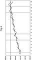
- FIG. 4 An example of continuous and intermittent compacting steps is illustrated in the graph of figure 4 , in which the continuous line represents a compacting step with application of a gradual load, whereas the jagged line represents the sequence of sub-steps of advancement and retreat of the presser element.
- the X-axis of figure 4 marks the sub-steps of application of the load and the Y-axis represents the corresponding values for the density of the product in powder, expressed in g/dm3.
- the compacting unit 2 comprises closing means that act on the compacting chamber(s) 13 during the compacting step performed by the presser element 17.
- the closing means are disabled, i.e. they allow access to the compacting chamber 13, at the first loading station 4 to allow the dose of product in powder 3 to be loaded into the compacting chamber, and at the transfer station 7 to allow the compacted dose of product in powder 5 to be transferred from the compacting chamber 13 to the filling unit 6.
- the closing means of the compacting unit 2 comprise a fixed wall 18 that extends at least for a section between the first loading station 4 and the transfer station 7 along a direction of the path of the first transporting element.
- the fixed wall 18 is arranged so that it closes the compacting chamber 13 during its advancement between the first loading station 4 and the first transfer station 7.
- the presser element 17 is configured for compacting the dose of product in powder 3 against the fixed wall 18.
- the wall 18 can be made by means of a cylindrical sleeve that envelops the drum 14 and that has at least two openings arranged at the first loading station 4 and at the first transfer station 7.
- the compacting chambers 13 are made to advance by the drum 14 inside the fixed wall 18 that keeps them closed in contrast to the radial push exerted by the presser element 17 during the compacting step.
- the fixed wall 18 is advantageously made flat.
- the filling unit 6 which comprises a second transporting element, preferably of the rotary type, and even more preferably made by means of a drum 19, rotating about an axis of rotation 20 (in a clockwise direction in figure 1 ).
- the drum 14 of the compacting unit 2 and the drum 19 of the filling unit 6 are arranged with their respective axes of rotation parallel, preferably horizontally. Moreover the drum 14 of the compacting unit 2 and the drum 19 of the filling unit 6 are tangential, defining the first transfer station 7 in the area of the respective tangent points.
- the second transporting element has a filling chamber 21, preferably a plurality of filling chambers 21, designed to be coupled with a container 9 at a second loading station 22.
- each compacting chamber 13 of the compacting unit 2 will be facing and aligned with a filling chamber 21 of the filling unit 6 (so that the transfer of the product from the compacting chamber 13 to the filling 21 can take place, as illustrated in figure 1 ).
- the second transporting element is configured to advance the filling chamber 21 along a second feed path "P2".
- the second transporting element is configured to advance the filling chamber 21 of the second loading station 22 to the first transfer station 7, to receive the compacted dose of product in powder 5.
- the second transporting element is configured to advance the filling chamber 21 from the first transfer station 7 to a second transfer station 23 to make available the package being processed 8, defined by the container 9 filled with compacted dose of product in powder 5.
- the second transporting element and in particular the drum 19, is configured to successively advance the filling chambers 21 along the second feed path "P2".
- the filling chambers 21 are regularly spaced along the second transporting element and along the second feed path "P2".
- the second transporting element is preferably operable in step with the filling chambers 21, analogous with the previous description with reference to the first transporting element.
- drum 14 of the compacting unit 2 and the drum 19 of the filling unit 6 are operated in step in such a manner that in the first transfer station 7 a compacting chamber 13 and a filling chamber 21 become aligned, with their respective access openings facing one another.
- each filling chamber 21 of the drum 19 extends radially between a radially external access opening 24 and a bottom that is radially internal, preferably made by means of a further presser element 25, or piston, which can be structurally and functionally analogous to the presser element 17 of the compacting chamber 13.
- the further presser element 25 is movable inside the filling chamber 21 in a radial direction, with a centrifugal or centripetal directional movement.
- the filling chamber 21 consists of a spindle with opposite openings with the further presser element 25 sliding inside it.
- the shape of the filling chamber 21 substantially reproduces the form that the final brick package will have.
- the shape of the filling chamber is substantially the same as that of the compacting chamber 13.
- the container 9 of deformable material is in the form of a sleeve that is open at its opposite extremities and arranged to envelop from the outside the spindle which represents the filling chamber 21.
- Figure 1 illustrates, at the first transfer station 7, a block of product which has been partially transferred from the compacting chamber 13 to the filling chamber 21: evidently, the presser element 17 is moved radially in a centrifugal direction as the further presser element 25 is moved radially in a centripetal direction, so as to produce the shifting, that is to say transfer, of the compact block of product from the compacting chamber 13 to the filling chamber 21.
- the further presser element 25 reaches a compacting position that is radially intermediate, for example just before the second transfer station 23. Proceeding with the radial centrifugal motion, the further presser element 25 reaches a radially external position for the expulsion of the package being processed 8 from the filling chamber 21, for example at the second transfer station 23.
- the further presser element 25 remains in a radially external position up to the first transfer station 7 (where it receives a new block of product).
- the filling unit 6 can comprise at least one filling chamber 21 and at least one further presser element 25 configured for further compacting the dose of product in powder 5 inside the filling chamber 21 and the container 9.
- Control elements are operationally associated with the further presser element 25 to activate the step in which the compacted dose of product in powder 5 inside the filling chamber 21 is compacted further.
- the control elements can comprise mechanical elements such as cams, elastic, pneumatic or hydraulic elements, and/or electronic or electromechanical systems.
- the control elements can be configured to activate a continuous mode or an intermittent mode for the compacting step, as described above with reference to the presser element 17.
- the filling unit 6 comprises closing means that act on the filling chamber(s) 21 during the further compacting step.
- the closing means are disabled, i.e. they allow access to the filling chamber 21, at least at the second loading station 22 to allow the filling chamber 21 to be loaded, at the first transfer station 7 to allow the compacted dose of product in powder 5 to be transferred into the filling chamber 21, and at the second transfer station 23 to allow the expulsion of the package being processed 8.
- intermediate sealing means 27 are provided along the second feed path "P2" which can be activated to operate on a part of the container 9, for example a bottom of the container 9.
- the intermediate sealing means 27 are arranged downstream from the first transfer station 7 and configured for folding and sealing the flaps of the bottom of the container 9 arranged at the access opening 24 of the filling chamber 21.
- the container 9, at the intermediate sealing means 27, is made to slide radially on the filling chamber 21 towards the exterior, until a part of the open container 9 is outside of the filling chamber 21, in order to effect the folding and sealing of the bottom.
- closing means for the filling unit 6 are arranged, which comprise a fixed wall 26 that extends at least for a section between the first transfer station 7 and the second transfer station 23 along a direction of the path of the first transporting element.
- the fixed wall 26 is arranged so that it counteracts the bottom of the container 9 as it advances between the first transfer station 7 and the second transfer station 23, so as to consolidate the closed bottom of the container 9.
- the further presser element 25 is configured for further compacting the compacted dose of product in powder against the fixed wall 26.
- the fixed wall 26 can be made by means of an angular portion of a cylindrical sleeve that partially envelops the drum 19.
- the pushing elements allow the bottom of the container 9 which has just been closed, to be consolidated.
- the fixed wall 26 is advantageously made flat.
- the machine 1 can comprise a transport line 28 that extends at least between the second transfer station 23 and the vacuum chamber 10 to transport the packages being processed 8 along a third feed path "P3".
- the machine 1 comprises folding and pre-sealing means 29, arranged along the third feed path "P3" and configured for the folding and pre-sealing of the extremities of the packages being processed 8 that are still open, before inserting them into the vacuum chamber 10.
- pre-sealing is intended to mean a partial sealing of the flaps of the packages being processed 8.
- These folding and pre-sealing elements 29 are arranged upstream from the vacuum chamber 10.
- the machine 1 for packaging is able to implement a packaging method for products in powder inside a container, for example ground coffee, according to the present invention.
- this method involves loading a dose of product in powder 3 inside a compacting chamber 13 and compacting this dose of product in powder inside the compacting chamber in order to obtain a compacted dose of product in powder 5.
- the compacted dose of product in powder 5 is transferred inside a container 9 to provide a package being processed 8, defined as a container 9 filled with the compacted dose of product in powder 5.
- a container 9 filled with the compacted dose of product in powder 5.
- the package being processed 8 is then transferred to a vacuum chamber in which it is closed and sealed during a vacuum activation step inside that vacuum chamber.
- the method according to the present invention involves loading the compacting chamber 13 by means of the loading hopper 12, then proceeds with a volumetric dosing of the product in powder to obtain the dose of product in powder 3.
- the drum 14 is made to rotate around axis 15 (counterclockwise in figure 1 ) so as to advance the compacting chamber 13 from the first loading station 4 to the first transfer station 7 and vice versa, preferably in a stepped, intermittent advancing motion with the compacting chambers 13 made in the drum 14.
- the compacting chamber 13 encounters the fixed wall 18 which closes its access opening 16.
- the presser element 17 is then moved (in a centrifugal direction) against the fixed wall 18 (centrifugal movement) thereby creating the compacting step of the dose of product in powder contained in the compacting chamber 13.
- This compacting step can be carried out in a continuous mode, gradually increasing the pressure exercised by the presser element 17, or in an intermittent mode, as described previously.
- the presser element 17 is then moved against the fixed wall 18 with the compacting chamber 13 stationary (in other words, when the compacting unit 2 is not in rotation).
- the compacting can take place in a continuous fashion.
- the compacting step occurs inside the compacting chamber as the latter is made to advance towards the first transfer station 7.
- the drum 19 of the filling unit 6 rotates (in a clockwise direction, with reference to figure 1 ), and in step with the drum 14 of the compacting unit 2.
- the container 9 is arranged onto the filling chamber 21 at the second loading station 22. More particularly, in this step the container 9 consists of a sleeve with open opposite ends.
- This container 9 in the shape of a sleeve envelops the filling chamber 21, adhering to the external surface of the latter.
- the filling chamber 21 (with the container wrapped around its exterior) reaches the first transfer station 7, the compacted dose of product in powder 5 is transferred inside the filling chamber 21 and then inside the container 9 arranged to envelop the filling chamber.
- a step can advantageously be arranged in which the compacted dose of product in powder 5 is compacted further inside the filling chamber 21. Also this step of further compacting is carried out in an intermittent mode as previously described, or alternatively in a continuous mode.
- the filling chamber 21 reaches the intermediate sealing means 27 which act on a part of the bottom end of the container 9 in the shape of a sleeve, to fold and close it.
- the sleeve is made to slide radially outwards along the filling chamber 21 in advance in order to make the part of the bottom end available for the folding and sealing that is to follow.
- the filling chamber 21 encounters the fixed wall 26 which counteracts the bottom of the container which finds itself at the access opening 24.
- the further presser element 25 is then moved against the fixed wall (centrifugal movement), thus effecting the step of further compacting the compacted dose of product in powder 5 contained in the filling chamber 21.
- the further compacting step occurs in the filling chamber 21 as the latter is made to advance towards the second transfer station 23 where the package being processed 8 is transferred to the transport line 28.
- the package being processed 8 is removed from the filling chamber 21 (by means of the push of the further presser element 25 against the compacted product in powder 5) in such a manner that the compacted product in powder 5 comes into direct contact with the inside of the package being processed 8.
- the packages being processed 8 encounter the folding and pre-sealing means 29 which fold and pre-seal a part of the package 8 before inserting it into the vacuum chamber 10.
- the folding and pre-sealing means 29 fold the end of the sleeve that is still open and that will then be sealed in the vacuum chamber, during a vacuum activation step inside that vacuum chamber.
- Said pre-sealing means are configured for partially closing the packages being processed 8, leaving open at least a channel, i.e. an area of access to the interior of the container.
- the folding and pre-sealing means 29 apply the folding and partial sealing of the upper flaps of the container 8, thereby creating a kind of fin at the top of the container.
- the sealing means 11 then permanently close the containers by sealing them, in other words apply the closure of the channel, i.e. the area of access (after the air has been extracted).
- the force of compression preferably exercised by the presser element 17 or by the further presser element 25 is between 10.000 and 50.000 N, and even more preferably between 20.000 and 30.000 N.
- the pressure inside the vacuum chamber 10 is preferably between -0.9 and -0.7 bar (the pressure has a negative value, as the chamber is under vacuum).
- An advantage of the present invention is that the packaging machine 1 of the invention is able to package products in powder inside a container in a fashion that is particularly simple, quick, and able to ensure an end result of the highest quality.
- a further advantage of the present invention is that the machine 1 of the invention is simple and reliable and that the packaging method of the invention is quick but still ensures that the end product is of the highest quality.
- a further advantage according to the present invention is that in the machine 1 of the invention the density of the product inside the container is homogeneous.
- a further advantage according to the present invention is that in the machine 1 of the invention the amount of air inside the brick package is extremely reduced, thus making it possible to have a particularly high degree of compaction of the product.
- a further advantage according to the present invention is that the machine 1 of the invention has extremely reduced operating times (in particular with regard to the step of closing and sealing the packages being processed 8 inside the vacuum chamber, where the operating times are four times lower compared to the systems of the prior art).
- a further advantage according to the present invention is that in the machine 1 of the invention it is substantially avoided that the product in powder becomes dispersed during the steps of arranging the packages being processed 8 inside the vacuum chamber.
- the vacuum chamber is not a critical point, thanks to the fact that, different from the prior art, it is advantageously arranged that the doses of product in powder are compacted before being inserted into the container.
Landscapes
- Engineering & Computer Science (AREA)
- Mechanical Engineering (AREA)
- Chemical & Material Sciences (AREA)
- Dispersion Chemistry (AREA)
- Quality & Reliability (AREA)
- Basic Packing Technique (AREA)
- Vacuum Packaging (AREA)
Abstract
Description
- The present invention concerns a machine and a method for packaging products in powder inside a container made of deformable material (in order to create so-called "brick" packaging).
- More particularly the present invention refers to the field of packaging for food products in powder, for example products intended for infusion and/or extraction like coffee or similar, or soluble products.
- Throughout the present description and in the enclosed claims, the term brick package is intended to refer to a container, generally made of a plastic, aluminium, or multilayer material, inside of which a food product is held and which has a generally parallelepiped shape which is kept by means of the vacuum to which it has been subjected before being closed.
- In what follows reference is made to the packaging of coffee, but not at the exclusion of any other particular details.
- For the packaging of coffee in containers in order to create a brick package it is known to take loose coffee in powder form and put a certain amount in a container. The container is then placed inside a vacuum chamber (autoclave) where it is given a brick shape, subjected to a vacuum and sealed.
- It should be observed that in the apparatuses of the prior art there is, generally speaking, a plurality of product release stations, in an attempt to optimise the distribution of the product inside the container. Moreover in these apparatuses of the prior art there are, generally speaking, vibrating elements to optimise the homogenisation of the product inside the container and consequently to obtain a homogeneous distribution of product density which will benefit the aesthetic aspect of the finished package.
- In practice, after the dose-adding step, the product that has fallen into the container is subjected to vibrations to allow for the subsequent dose to be added, and so on until the preset quantity has been reached.
- The Applicant has noted that the prior art presents some drawbacks, both from a structural and from a functional point of view.
- In the first place, in fact, the need for a plurality of stations to release the product, as well as the need for vibrating elements, adds a certain complexity to the construction.
- It should furthermore be observed that, generally speaking, in the apparatuses of the prior art further compacting elements are present inside the vacuum chamber, needed to obtain the characteristic brick shape of the container.
- Secondly, the vacuum chamber must guarantee a closed, perfectly sealed atmosphere, which makes it particularly complex to include and operate the devices that complete the packaging by compacting the loose powder and folding, sealing and closing the container. In fact, precisely because of the presence of loose powder inside the container, the vacuum chamber must have opportune and suitable seats for the containers and the containers must be kept in position while the loose powder is compacted and the container is closed and sealed.
- Eventually, following the aspiration generated inside the vacuum chamber, some particles of loose powder could reach the sealing area, thus preventing the correct sealing of the brick and causing the unexpected loss of the vacuum seal and as a result the loss of the characteristic brick shape. The powder could even escape from the container altogether when the latter is not yet folded and sealed, and be deposited inside the vacuum chamber itself and on the devices contained therein.
- In order to overcome these drawbacks, the obtainment of the vacuum required (typically 0,7 ÷-0,9 bar) in the vacuum chamber occurs over an 8-10 second time span. In some cases, in order to speed up the packaging, packaging machines have been arranged with two or more vacuum chambers, which causes, as a collateral effect, an incremental complexity in the machine and its operation.
- In the present day, therefore, some exigencies are particularly felt, among which are how to accelerate packaging time without increasing the complexity of the machine itself, how to limit the structural and functional complexity of the vacuum chamber, and how to optimise the volume of the powder inside the container while avoiding the dispersion of particles inside the vacuum chamber.
- The aim of the present invention is therefore that of providing a machine and a method for packaging suitable for the packaging of products in powder inside a container in a particularly simple and quick manner while guaranteeing that the end result is of the highest quality.
- More particularly one aim of the present invention is to provide a machine for the packaging of products in powder inside a container that is simple and reliable.
- A further aim of the present invention is that of providing a packaging method for products in powder inside a container in order to create a brick package, which is fast but which also guarantees that the end product is of the highest quality.
- The technical characteristics of the invention in accordance with the above-mentioned aims, are clearly present in the claims provided hereunder, and the advantages of the same will become even clearer in the detailed description that follows, in which reference is made to the enclosed figures which illustrate a purely explanatory and non-limiting embodiment, wherein:
-
figure 1 illustrates a schematic front view of a machine for packaging products in powder inside a container according to a possible embodiment of the invention; -
figure 2 andfigure 3 illustrate respective enlargements of details fromfigure 1 ; -
figure 4 illustrates a graph representing the density of the product in powder as a function of the sub-steps of the application of the load. - In accordance with the enclosed drawings, the
number 1 indicates a machine for packaging products in powder inside a container made of deformable material, preferably food products in powder form, and even more preferably ground coffee. - According to the invention the
machine 1 for packaging comprises a compactingunit 2 configured to receive a dose of product inpowder 3 at afirst loading station 4, and compact it in order to obtain a compacted dose of product inpowder 5. - Furthermore the
machine 1 comprises afilling unit 6 configured to receive, at afirst transfer station 7, the compacted dose of product inpowder 5 coming from the compactingunit 2 and to provide a package being processed 8 defined by acontainer 9 made of deformable material filled with the compacted dose of product inpowder 5. - The term deformable material should be interpreted as any material that is able to be formed in the shape of a compact brick that is in close contact with a dose of product in powder after the air is extracted from its interior. As a non-limiting example, the composite PE / ALU / PET presents the characteristics needed to be a deformable material.
- According to the invention the
machine 1 for packaging further comprises avacuum chamber 10 designed to receive the package being processed coming from thefilling unit 6 and to extract air from the package being processed 8, in such a way as to make the deformable material of thecontainer 9 adhere to the compacted dose of product inpowder 5 placed inside the package being processed 8; and sealing means 11 positioned in the vacuum chamber and configured to close and seal the package being processed 8 during a step of activating a vacuum in the vacuum chamber and to obtain closed and sealed packages. - In the course of this description and the enclosed claims, the term "container" is intended to mean a container not yet closed and sealed, in which only some of the sides have been joined, folded and sealed, therefore. Furthermore the term "package being processed" is intended to indicate the
container 9 together with the compacted dose of product inpowder 5 which has been inserted into it. This definition applies from the moment of insertion of the compacted dose of product inpowder 5 into thecontainer 9, up to the complete closing, sealing and application of the vacuum to the container, which is designed to result in a brick package. - According to a possible embodiment, the
first loading station 4 is defined at aloading hopper 12 designed to receive the product in powder and direct it towards the compactingunit 2 where it is divided into doses. Preferably the dividing into doses occurs by means of a volumetric dosage system, not illustrated. - It should be observed that, in a more general sense, the
first loading station 4 can comprise any kind of feeding device (e.g. volumetric dosage system, auger, etc.). - The following will describe the compacting
unit 2 which comprises at least onecompacting chamber 13 designed to receive the dose of product inpowder 3 at thefirst loading station 4, in particular to receive the dose of product inpowder 3 from theloading hopper 12. - Preferably the
compacting unit 2 comprises adrum 14, rotating about an axis of rotation 15 (in a counterclockwise direction infigure 1 ), which defines a first transporting element. - Preferably the first transporting element, and in particular the
drum 14, has a plurality of compactingchambers 13. - The transporting element, and in particular the
drum 14, is configured to successively advance thecompacting chambers 13 of thefirst loading station 4 to thefirst transfer station 7, and vice versa, along a first feed path "P1". - According to a possible embodiment, the
compacting chambers 13 are regularly spaced along the first transporting element and along the first feed path "P1". In this case the first transporting element is preferably operable in step with thecompacting chambers 13. In other words the transporting element advances thecompacting chambers 13 in an intermittent fashion, proceeding at a stepped sequence whose steps correspond to the steps at which thecompacting chambers 13 are distributed. - According to a possible embodiment, of which the enclosed drawings illustrate a non-limiting example, each compacting
chamber 13 of thedrum 14 extends radially between an access opening 16 radially outside and a bottom that is radially inside and preferably made by means of apresser element 17, or piston. - In practice, the
compacting chamber 13 consists of a spindle with opposite openings with thepresser element 17 sliding inside it. - The shape of the
compacting chamber 13 substantially reproduces the form that the final brick package will have. - The
presser element 17 is movable inside thecompacting chamber 13 in a radial direction (in a centrifugal or centripetal direction). - In particular, it is observed that in the position in which the compacting
chamber 13 is found at thefirst loading station 4, thepresser element 17 is first arranged in a position that is radially outside (not illustrated) and subsequently, during the loading of the product, it is moved in a radial centripetal direction in such a manner as to (gradually) increase the volume of the compacting chamber 13 (and incorporate a greater quantity of product). - In this manner, advantageously, seeing as how the compacting
chamber 13 is always filled with product, the creation of areas filled with air during the loading of the product inside the compactingchamber 13 is avoided. - It should be observed, therefore, that in this manner the compacting is extremely effective and the density of the powder in
chamber 13 is homogeneous. - With a radial centrifugal motion the
presser element 17 reaches a compacting position that is radially intermediate, corresponding for example to the position in which the compacted dose of product inpowder 5 is received, in other words just before the first transfer station 7 (for example the position diametrically opposite theloading hopper 12, with reference to the embodiment offigure 1 ). Proceeding in a radial centrifugal motion, thepresser element 17 reaches a radially external position for the expulsion of the compacted dose of product inpowder 5 from thecompacting chamber 13, at thefirst transfer station 7. -
Figure 1 illustrates a block of coffee at thefirst transfer station 7 which has not yet been completely expelled from the compactingchamber 13. - After the expulsion of the compacted dose of product in
powder 5, thepresser element 17 remains in this radial position up to the loading station 4 (where it receives new product and will be moved in a radial centripetal direction during the loading). - In general terms, therefore, the
compacting unit 2 comprises at least acompacting chamber 13 and at least apresser element 17 configured for compacting the dose of product inpowder 3 inside thecompacting chamber 13. In the case of a plurality of chambers, preferably apresser element 17 configured for compacting the dose of product in powder is associated with eachcompacting chamber 13. - Control elements, not illustrated, are operationally associated with the
presser element 17 to activate the compacting step in which the product in powder inside thecompacting chamber 13 is compacted. The control elements can comprise mechanical elements such as cams, elastic, pneumatic or hydraulic elements, and/or electronic or electromechanical systems. - The control elements can be configured to activate the compacting step with a continuous mode and such as to generate a progressively increasing load value exercised by the
presser element 17. Alternatively, and according to a preferred embodiment, the control elements are configured to activate an intermittent mode for the compacting step, between a maximum load value and a minimum load value exercised by the presser element. The maximum and minimum load values preferably increase as the compacting step progresses. In other words, thepresser element 17 is made to advance from the position that is radially inside, to a first compacting position that is radially intermediate and that corresponds to a first maximum load value for the load exercised on the product in powder. Subsequently the presser element is made to move back so as to apply a first minimum load value. The advancement and retreat of the presser element constitutes a sub-step of the compacting step. Subsequently this sub-step is repeated several times, each time increasing the maximum and minimum load values applied. - An example of continuous and intermittent compacting steps is illustrated in the graph of
figure 4 , in which the continuous line represents a compacting step with application of a gradual load, whereas the jagged line represents the sequence of sub-steps of advancement and retreat of the presser element. The X-axis offigure 4 marks the sub-steps of application of the load and the Y-axis represents the corresponding values for the density of the product in powder, expressed in g/dm3. - In accordance with a possible embodiment, the compacting
unit 2 comprises closing means that act on the compacting chamber(s) 13 during the compacting step performed by thepresser element 17. Preferably the closing means are disabled, i.e. they allow access to the compactingchamber 13, at thefirst loading station 4 to allow the dose of product inpowder 3 to be loaded into the compacting chamber, and at thetransfer station 7 to allow the compacted dose of product inpowder 5 to be transferred from the compactingchamber 13 to thefilling unit 6. - According to a possible embodiment, of which the enclosed drawings illustrate a non-limiting example, the closing means of the compacting
unit 2 comprise a fixedwall 18 that extends at least for a section between thefirst loading station 4 and thetransfer station 7 along a direction of the path of the first transporting element. The fixedwall 18 is arranged so that it closes the compactingchamber 13 during its advancement between thefirst loading station 4 and thefirst transfer station 7. Preferably thepresser element 17 is configured for compacting the dose of product inpowder 3 against the fixedwall 18. - It should be observed that, preferably, on the fixed
wall 18 there are pushingelements 50 that act by exerting a direct push that counterbalances the push of thepresser element 17. In this manner, advantageously, deformation of the wall itself as a result of the pushing action of thepresser element 17 is prevented. - With reference to the enclosed figures, but not at the exclusion of any other particular details, the
wall 18 can be made by means of a cylindrical sleeve that envelops thedrum 14 and that has at least two openings arranged at thefirst loading station 4 and at thefirst transfer station 7. The compactingchambers 13 are made to advance by thedrum 14 inside the fixedwall 18 that keeps them closed in contrast to the radial push exerted by thepresser element 17 during the compacting step. - At the areas where the push of the
presser element 17 and of the counterbalancing pushing elements occurs, the fixedwall 18 is advantageously made flat. - In the following the
filling unit 6 is described, which comprises a second transporting element, preferably of the rotary type, and even more preferably made by means of adrum 19, rotating about an axis of rotation 20 (in a clockwise direction infigure 1 ). - The
drum 14 of the compactingunit 2 and thedrum 19 of the fillingunit 6 are arranged with their respective axes of rotation parallel, preferably horizontally. Moreover thedrum 14 of the compactingunit 2 and thedrum 19 of the fillingunit 6 are tangential, defining thefirst transfer station 7 in the area of the respective tangent points. The second transporting element has a fillingchamber 21, preferably a plurality of fillingchambers 21, designed to be coupled with acontainer 9 at asecond loading station 22. - Preferably, in at least a zone of the respective path of movement (at the first transfer station 7) each compacting
chamber 13 of the compactingunit 2 will be facing and aligned with a fillingchamber 21 of the filling unit 6 (so that the transfer of the product from the compactingchamber 13 to the filling 21 can take place, as illustrated infigure 1 ). - The second transporting element is configured to advance the filling
chamber 21 along a second feed path "P2". In particular the second transporting element is configured to advance the fillingchamber 21 of thesecond loading station 22 to thefirst transfer station 7, to receive the compacted dose of product inpowder 5. Furthermore the second transporting element is configured to advance the fillingchamber 21 from thefirst transfer station 7 to asecond transfer station 23 to make available the package being processed 8, defined by thecontainer 9 filled with compacted dose of product inpowder 5. - The second transporting element, and in particular the
drum 19, is configured to successively advance the fillingchambers 21 along the second feed path "P2". - According to a possible embodiment, the filling
chambers 21 are regularly spaced along the second transporting element and along the second feed path "P2". In this case the second transporting element is preferably operable in step with the fillingchambers 21, analogous with the previous description with reference to the first transporting element. - In particular the
drum 14 of the compactingunit 2 and thedrum 19 of the fillingunit 6 are operated in step in such a manner that in the first transfer station 7 a compactingchamber 13 and a fillingchamber 21 become aligned, with their respective access openings facing one another. - According to a possible embodiment, of which the enclosed drawings illustrate a non-limiting example, each filling
chamber 21 of thedrum 19 extends radially between a radially external access opening 24 and a bottom that is radially internal, preferably made by means of afurther presser element 25, or piston, which can be structurally and functionally analogous to thepresser element 17 of the compactingchamber 13. - The
further presser element 25 is movable inside the fillingchamber 21 in a radial direction, with a centrifugal or centripetal directional movement. - In practice, the filling
chamber 21 consists of a spindle with opposite openings with thefurther presser element 25 sliding inside it. - The shape of the filling
chamber 21 substantially reproduces the form that the final brick package will have. - In practice the shape of the filling chamber is substantially the same as that of the compacting
chamber 13. - The
container 9 of deformable material is in the form of a sleeve that is open at its opposite extremities and arranged to envelop from the outside the spindle which represents the fillingchamber 21. - It is observed that when the
further presser element 25 is at thefirst transfer station 7, it is initially arranged in a position that is radially external, after which it is then moved radially in a centripetal direction during the transfer of the product from the compactingchamber 13 to the fillingchamber 21. -
Figure 1 illustrates, at thefirst transfer station 7, a block of product which has been partially transferred from the compactingchamber 13 to the filling chamber 21: evidently, thepresser element 17 is moved radially in a centrifugal direction as thefurther presser element 25 is moved radially in a centripetal direction, so as to produce the shifting, that is to say transfer, of the compact block of product from the compactingchamber 13 to the fillingchamber 21. - Subsequently, according to one embodiment, following a radial centrifugal motion, the
further presser element 25 reaches a compacting position that is radially intermediate, for example just before thesecond transfer station 23. Proceeding with the radial centrifugal motion, thefurther presser element 25 reaches a radially external position for the expulsion of the package being processed 8 from the fillingchamber 21, for example at thesecond transfer station 23. - After the expulsion, the
further presser element 25 remains in a radially external position up to the first transfer station 7 (where it receives a new block of product). - In general terms, therefore, the filling
unit 6 can comprise at least one fillingchamber 21 and at least onefurther presser element 25 configured for further compacting the dose of product inpowder 5 inside the fillingchamber 21 and thecontainer 9. Control elements, not illustrated, are operationally associated with thefurther presser element 25 to activate the step in which the compacted dose of product inpowder 5 inside the fillingchamber 21 is compacted further. Also in this case, as with thepresser elements 17, the control elements can comprise mechanical elements such as cams, elastic, pneumatic or hydraulic elements, and/or electronic or electromechanical systems. Furthermore the control elements can be configured to activate a continuous mode or an intermittent mode for the compacting step, as described above with reference to thepresser element 17. - According to a possible embodiment, the filling
unit 6 comprises closing means that act on the filling chamber(s) 21 during the further compacting step. The closing means are disabled, i.e. they allow access to the fillingchamber 21, at least at thesecond loading station 22 to allow the fillingchamber 21 to be loaded, at thefirst transfer station 7 to allow the compacted dose of product inpowder 5 to be transferred into the fillingchamber 21, and at thesecond transfer station 23 to allow the expulsion of the package being processed 8. - According to the illustrated embodiment, intermediate sealing means 27 are provided along the second feed path "P2" which can be activated to operate on a part of the
container 9, for example a bottom of thecontainer 9. - Preferably the intermediate sealing means 27 are arranged downstream from the
first transfer station 7 and configured for folding and sealing the flaps of the bottom of thecontainer 9 arranged at the access opening 24 of the fillingchamber 21. - In concrete terms the
container 9, at the intermediate sealing means 27, is made to slide radially on the fillingchamber 21 towards the exterior, until a part of theopen container 9 is outside of the fillingchamber 21, in order to effect the folding and sealing of the bottom. - According to an embodiment, of which the enclosed drawings illustrate a non-limiting example, downstream (in the direction of advancement P2) from the intermediate sealing means 27, closing means for the filling
unit 6 are arranged, which comprise a fixedwall 26 that extends at least for a section between thefirst transfer station 7 and thesecond transfer station 23 along a direction of the path of the first transporting element. The fixedwall 26 is arranged so that it counteracts the bottom of thecontainer 9 as it advances between thefirst transfer station 7 and thesecond transfer station 23, so as to consolidate the closed bottom of thecontainer 9. Preferably thefurther presser element 25 is configured for further compacting the compacted dose of product in powder against the fixedwall 26. - With reference to the enclosed figures, but not at the exclusion of any other particular details, the fixed
wall 26 can be made by means of an angular portion of a cylindrical sleeve that partially envelops thedrum 19. - It should be observed that, in an embodiment that is not illustrated here, on the fixed
wall 26 there are pushing elements (not illustrated) that act by exerting a direct push that counterbalances the push of thefurther presser element 25. In this manner, advantageously, deformation of the wall itself as a result of the pushing action of thefurther presser element 25 is prevented. - Furthermore, the pushing elements allow the bottom of the
container 9 which has just been closed, to be consolidated. - At the areas where the push of the
further presser element 21 and of the counterbalancing pushing elements occurs, the fixedwall 26 is advantageously made flat. - According to a possible embodiment, the
machine 1 can comprise atransport line 28 that extends at least between thesecond transfer station 23 and thevacuum chamber 10 to transport the packages being processed 8 along a third feed path "P3". Preferably themachine 1 comprises folding and pre-sealing means 29, arranged along the third feed path "P3" and configured for the folding and pre-sealing of the extremities of the packages being processed 8 that are still open, before inserting them into thevacuum chamber 10. The term pre-sealing is intended to mean a partial sealing of the flaps of the packages being processed 8. These folding andpre-sealing elements 29 are arranged upstream from thevacuum chamber 10. - In use, the
machine 1 for packaging is able to implement a packaging method for products in powder inside a container, for example ground coffee, according to the present invention. - According to a possible embodiment, this method involves loading a dose of product in
powder 3 inside a compactingchamber 13 and compacting this dose of product in powder inside the compacting chamber in order to obtain a compacted dose of product inpowder 5. - These steps can be implemented by the compacting
unit 2 described previously. - Subsequently the compacted dose of product in
powder 5 is transferred inside acontainer 9 to provide a package being processed 8, defined as acontainer 9 filled with the compacted dose of product inpowder 5. These steps can be implemented by the fillingunit 6 described previously. - The package being processed 8 is then transferred to a vacuum chamber in which it is closed and sealed during a vacuum activation step inside that vacuum chamber.
- With reference to a possible implementation in the
machine 1 previously described, the method according to the present invention involves loading the compactingchamber 13 by means of theloading hopper 12, then proceeds with a volumetric dosing of the product in powder to obtain the dose of product inpowder 3. Thedrum 14 is made to rotate around axis 15 (counterclockwise infigure 1 ) so as to advance the compactingchamber 13 from thefirst loading station 4 to thefirst transfer station 7 and vice versa, preferably in a stepped, intermittent advancing motion with the compactingchambers 13 made in thedrum 14. - To close the compacting
chamber 13 during the compacting step it is advantageously arranged that during the rotation of thedrum 14, the compactingchamber 13 encounters the fixedwall 18 which closes itsaccess opening 16. Thepresser element 17 is then moved (in a centrifugal direction) against the fixed wall 18 (centrifugal movement) thereby creating the compacting step of the dose of product in powder contained in the compactingchamber 13. - This compacting step can be carried out in a continuous mode, gradually increasing the pressure exercised by the
presser element 17, or in an intermittent mode, as described previously. - The
presser element 17 is then moved against the fixedwall 18 with the compactingchamber 13 stationary (in other words, when the compactingunit 2 is not in rotation). - Alternatively the compacting can take place in a continuous fashion.
- In other words, the compacting step occurs inside the compacting chamber as the latter is made to advance towards the
first transfer station 7. - The
drum 19 of the fillingunit 6 rotates (in a clockwise direction, with reference tofigure 1 ), and in step with thedrum 14 of the compactingunit 2. - Upstream from the
first transfer station 7, thecontainer 9 is arranged onto the fillingchamber 21 at thesecond loading station 22. More particularly, in this step thecontainer 9 consists of a sleeve with open opposite ends. - This
container 9 in the shape of a sleeve envelops the fillingchamber 21, adhering to the external surface of the latter. - When, after the rotation of the
drum 19, the filling chamber 21 (with the container wrapped around its exterior) reaches thefirst transfer station 7, the compacted dose of product inpowder 5 is transferred inside the fillingchamber 21 and then inside thecontainer 9 arranged to envelop the filling chamber. - Then a step can advantageously be arranged in which the compacted dose of product in
powder 5 is compacted further inside the fillingchamber 21. Also this step of further compacting is carried out in an intermittent mode as previously described, or alternatively in a continuous mode. - According to the illustrated embodiment, there is an intermediate closing step of the
container 9, preferably carried out before the further compacting step, if included. For example, after having left thefirst transfer station 7, the fillingchamber 21 reaches the intermediate sealing means 27 which act on a part of the bottom end of thecontainer 9 in the shape of a sleeve, to fold and close it. As described previously, the sleeve is made to slide radially outwards along the fillingchamber 21 in advance in order to make the part of the bottom end available for the folding and sealing that is to follow. - Subsequently the filling
chamber 21 encounters the fixedwall 26 which counteracts the bottom of the container which finds itself at theaccess opening 24. - The
further presser element 25 is then moved against the fixed wall (centrifugal movement), thus effecting the step of further compacting the compacted dose of product inpowder 5 contained in the fillingchamber 21. The further compacting step occurs in the fillingchamber 21 as the latter is made to advance towards thesecond transfer station 23 where the package being processed 8 is transferred to thetransport line 28. In thesecond transfer station 23 the package being processed 8 is removed from the filling chamber 21 (by means of the push of thefurther presser element 25 against the compacted product in powder 5) in such a manner that the compacted product inpowder 5 comes into direct contact with the inside of the package being processed 8. - Preferably, before reaching the
vacuum chamber 10, the packages being processed 8 encounter the folding and pre-sealing means 29 which fold and pre-seal a part of thepackage 8 before inserting it into thevacuum chamber 10. In particular the folding and pre-sealing means 29 fold the end of the sleeve that is still open and that will then be sealed in the vacuum chamber, during a vacuum activation step inside that vacuum chamber. - Said pre-sealing means are configured for partially closing the packages being processed 8, leaving open at least a channel, i.e. an area of access to the interior of the container.
- In practice, the folding and pre-sealing means 29 apply the folding and partial sealing of the upper flaps of the
container 8, thereby creating a kind of fin at the top of the container. - In this case, in the
vacuum chamber 10, the sealing means 11 then permanently close the containers by sealing them, in other words apply the closure of the channel, i.e. the area of access (after the air has been extracted). - It should be observed that, according to the present invention, the time each brick package has to stay inside the vacuum chamber in order to be processed, is significantly reduced with respect to the prior art, with a correspondingly increased speed of the machine as a result.
- According to another aspect, the force of compression preferably exercised by the
presser element 17 or by thefurther presser element 25 is between 10.000 and 50.000 N, and even more preferably between 20.000 and 30.000 N. - According to yet another aspect, the pressure inside the
vacuum chamber 10 is preferably between -0.9 and -0.7 bar (the pressure has a negative value, as the chamber is under vacuum). - An advantage of the present invention is that the
packaging machine 1 of the invention is able to package products in powder inside a container in a fashion that is particularly simple, quick, and able to ensure an end result of the highest quality. - A further advantage of the present invention is that the
machine 1 of the invention is simple and reliable and that the packaging method of the invention is quick but still ensures that the end product is of the highest quality. - A further advantage according to the present invention is that in the
machine 1 of the invention the density of the product inside the container is homogeneous. - A further advantage according to the present invention is that in the
machine 1 of the invention the amount of air inside the brick package is extremely reduced, thus making it possible to have a particularly high degree of compaction of the product. - A further advantage according to the present invention is that the
machine 1 of the invention has extremely reduced operating times (in particular with regard to the step of closing and sealing the packages being processed 8 inside the vacuum chamber, where the operating times are four times lower compared to the systems of the prior art). - A further advantage according to the present invention is that in the
machine 1 of the invention it is substantially avoided that the product in powder becomes dispersed during the steps of arranging the packages being processed 8 inside the vacuum chamber. - In the machine and the method according to the invention the vacuum chamber is not a critical point, thanks to the fact that, different from the prior art, it is advantageously arranged that the doses of product in powder are compacted before being inserted into the container.
- This also makes it possible to improve the quality of the end product, by performing the compacting steps in a manner that is most suitable for the type of material in powdered form.
- Furthermore it is possible to introduce further compacting steps, which contributes to improving the quality of the end product and eliminates the concerns that the vacuum chamber presents.
Claims (16)
- A machine (1) for packaging products in powder, for example coffee powder, inside a container made of deformable material, characterised in that it comprises:- a compacting unit (2) comprising a compacting chamber (13) configured to receive a dose of product in powder (3), at a first loading station (4),- a presser element (17) configured to compact the dose of product in powder (3) inside the compacting chamber (13) in such a way as to obtain a compacted dose of product in powder (5),- a filling unit (6) comprising at least a filling chamber (21) configured to receive, at a first transfer station (7), the compacted dose of product in powder (5) coming from the compacting unit (2) and to provide a package being processed (8) defined by a container (9) made of deformable material filled with the compacted dose of product in powder (5),- a vacuum chamber (10) designed to receive the package being processed (8) coming from the filling unit (6) and to extract air from the package being processed (8), in such a way as to make the deformable material of the container (9) adhere to the compacted dose of product in powder (5),- sealing means (11) positioned in the vacuum chamber (10) and configured to close and seal the package being processed (8) during a step of activating vacuum in the vacuum chamber (10).
- The packaging machine according to the preceding claim, wherein the compacting unit (2) comprises a first transporting element, preferably of the rotary type, having the compacting chamber (13), the first transporting element being configured to feed the compacting chamber (13) from the first loading station (4) to the first transfer station (7) and vice versa along a first feed path (P1).
- The packaging machine according to claim 1 or 2, wherein the compacting unit (2) comprises closing means acting on the compacting chamber (13) during the compaction step actuated by the presser element (17) and deactivated at the first loading station (4) and the first transfer station (7) to allow the loading the dose of product in powder (3) in the compacting chamber (13) and to allow the transfer of the compacted dose of product in powder (5) from the compacting chamber (13) to the filling unit (6).
- The packaging machine according to claim 2 or 3, wherein the closing means comprise a fixed wall (18) extending at least for a stretch between the first loading station (4) and the first transfer station (7) according to a direction of travel of the first transporting element, the fixed wall (18) being positioned for closing the compacting chamber (13) during its movement between the first loading station (4) and the first transfer station (7), the presser element (17) being configured to compact the dose of product in powder (3) against the fixed wall (18).
- The packaging machine according to any one of claims 2 to 4, wherein the first transporting element is a drum (14), rotating about an axis of rotation (15), and wherein each compacting chamber (13) extends radially between an access opening (16) radially outside and the presser element (17), movable inside the compacting chamber (13) in a radial direction between a loading position, wherein the presser element (7) moves in the centripetal direction to allow the insertion of the dose of product in powder in the compacting chamber (7), a compacting position, wherein the presser element (7) acts in a centrifugal direction against the dose of product in powder loaded in the compacting chamber (13), and a position of expulsion, wherein the presser element (7) moving in the centrifugal direction reaches the radially external position, thus expelling the compacted dose of product in powder (5) from the compacting chamber (13).
- The packaging machine according to any one of the preceding claims, wherein the filling chamber (21) is configured to be wrapped around by the container made of deformable material (9) at a second loading station (22), the filling unit (6) being configured to feed the filling chamber (21) from the second loading station (22) to the first transfer station (7), to receive the compacted dose of product in powder (5) inside the filling chamber (21), and from the first transfer station (7) to a second transfer station (23) to provide a package being processed (8) defined by the container (9) filled with the compacted dose of product in powder (5), along a second feed path (P2).
- The packaging machine according to the preceding claim, comprising intermediate sealing means (27) positioned along the second feed path (P2) and which can be activated on a portion of the container (9).
- The packaging machine according to any one of the preceding claims, comprising a further presser element (25) configured for further compacting inside the filling chamber (21) the compacted dose of product in powder (5).
- The packaging machine according to the preceding claim, wherein the filling unit (6) comprises closing means acting on the filling chamber (21) during the further compacting step actuated by the further presser element (25) and deactivated at least at the first transfer station (7) and the second transfer station (23).
- The packaging machine according to the preceding claim, wherein the closing means comprise a fixed wall (26) extending at least for a stretch between the first transfer station (7) and the second transfer station (23) according to a direction of travel of the filling unit (6), the fixed wall (26) being positioned to close the filling chamber (21) during its movement between the first transfer station (7) and the second transfer station (23).
- The packaging machine according to any one of claims 8 or 10, wherein the filling unit (6) comprises a drum (19), rotating about an axis of rotation (20), and wherein each filling chamber (21) extends radially between an access opening (24) radially external and the further presser element (25), movable inside the filling chamber in a radial direction between a loading position, wherein the further presser element (25) moves in the centripetal direction to allow the insertion of the compacted dose of product in powder (5) in the filling chamber (21), a further compacting position, wherein the further presser element (25) acts in a centrifugal direction against the compacted dose of product in powder (5) loaded in the filling chamber (21), and a position of expulsion, wherein the further presser element (25) moving in the centrifugal direction reaches the radially external position, thus expelling the compacted dose of product in powder (5) and the container (9) for making the package being processed (8) with inside the dose of product in powder (5) further compacted.
- A method for packaging products in powder, for example coffee powder, inside a container, characterised in that it comprises the following steps:- loading a dose of product in powder (3) inside a compacting chamber (13),- compacting the dose of product in powder (3) inside the compacting chamber (13) to obtain a compacted dose of product in powder (5),- set up/arrange a container made of deformable material- transferring the compacted dose of product in powder (5) inside a container (9) made of deformable material in order to provide a package being processed (8) defined by a container (9) filled with the compacted dose of product in powder (5),- transferring the package being processed (8) to a vacuum chamber (10),- closing and sealing the package being processed (8), inside the vacuum chamber (10) during a step for activating the vacuum in the vacuum chamber (10), the activation of the vacuum being realized in such a way as to extract the air from the package being process (8) up to allow the deformable material of the container (9) to adhere to the compacted dose of product in powder (5) positioned inside the package being process (8),
- The packaging method according to the preceding claim, comprising the step of feeding the compacting chamber (13) from a first loading station (4) to a first transfer station (7) and vice versa along a first feed path (P1), preferably using an intermittent feed motion.
- The packaging method according to claim 12 or 13, wherein the compacted dose of product in powder (5) is transferred inside a filling chamber (21) on which the container (9) made of deformable material is wrapped, the filling chamber (21) being fed along a second feed path (P2) preferably using an intermittent feed motion.
- The packaging method according to the preceding claim, comprising the step of further compacting the compacted dose of product in powder (5) inside the filling chamber (21), preferably after having closed the filling chamber.
- The packaging method according to any one of claims 12 to 15, comprising, before the step of transferring the package being processed (8) to a vacuum chamber (10), the step of pre-sealing edges of the package being processed (8), so as to leave channels for extracting air facing and open towards the inside of the package being processed (8).
Applications Claiming Priority (1)
| Application Number | Priority Date | Filing Date | Title |
|---|---|---|---|
| IT102017000077084A IT201700077084A1 (en) | 2017-07-10 | 2017-07-10 | MACHINE AND PACKAGING METHOD OF POWDER PRODUCTS, FOR EXAMPLE COFFEE POWDER, WITHIN A CONTAINER. |
Publications (2)
| Publication Number | Publication Date |
|---|---|
| EP3428075A1 true EP3428075A1 (en) | 2019-01-16 |
| EP3428075B1 EP3428075B1 (en) | 2021-12-29 |
Family
ID=60990885
Family Applications (1)
| Application Number | Title | Priority Date | Filing Date |
|---|---|---|---|
| EP18182340.2A Active EP3428075B1 (en) | 2017-07-10 | 2018-07-09 | Machine and method for packaging powder products inside a container made of deformable material |
Country Status (3)
| Country | Link |
|---|---|
| EP (1) | EP3428075B1 (en) |
| ES (1) | ES2909628T3 (en) |
| IT (1) | IT201700077084A1 (en) |
Cited By (5)
| Publication number | Priority date | Publication date | Assignee | Title |
|---|---|---|---|---|
| CN110171611A (en) * | 2019-05-25 | 2019-08-27 | 上海仅上包装设备有限公司 | A kind of vacuum nitrogen gas sealing machine |
| CN113815971A (en) * | 2020-10-20 | 2021-12-21 | 怀化五零三侗医药科技开发有限公司 | Camphor powder packing and press-fitting equipment |
| CN115447813A (en) * | 2022-09-09 | 2022-12-09 | 合肥昊翔汽车零部件有限公司 | Automobile active carbon automatic filling toner equipment and filling method thereof |
| CN118953841A (en) * | 2024-10-15 | 2024-11-15 | 江苏创元环保新材料有限公司 | A conveying device for gypsum powder processing |
| CN119610664A (en) * | 2023-09-14 | 2025-03-14 | 苏州中瑞智创三维科技股份有限公司 | A quantitative powder dropping device for SLM equipment |
Citations (9)
| Publication number | Priority date | Publication date | Assignee | Title |
|---|---|---|---|---|
| DE697209C (en) * | 1937-12-19 | 1940-10-08 | Koelner Werkzeugmaschinenfabri | Method and device for packing fibrous goods |
| DE2109834A1 (en) * | 1971-03-02 | 1972-09-14 | Treckmann, Paul, 6146 Aisbach | Machine for the automatic packing of loose material in bags |
| US4154045A (en) * | 1976-11-17 | 1979-05-15 | Esseltepac Aktiebolag | Method of packing powder formed products |
| US5097648A (en) * | 1990-04-26 | 1992-03-24 | Robert Bosch Gmbh | Apparatus for evacuating and closing bag package |
| DE19637615C1 (en) * | 1996-09-16 | 1997-10-02 | Bosch Gmbh Robert | Packing powder or granular bulk material |
| SE519425C2 (en) * | 2002-01-16 | 2003-02-25 | Rocker Production Ab | Preparing packaged portions of powder material, by compacting portions, transferring into compartments and dropping onto strip of packaging material |
| DE102007053034A1 (en) * | 2007-11-07 | 2009-05-14 | Robert Bosch Gmbh | Containers filling device for filling e.g. coffee powder, has thermoforming device with transporting device serving as integral part, where uninterrupted sequence is executed from forming of container till filling of container |
| WO2015118450A1 (en) * | 2014-02-06 | 2015-08-13 | I.M.A. Industria Macchine Automatiche S.P.A. | Unit and method for releasing product for extraction or infusion beverages in containers forming single-use capsules or pods |
| WO2016020822A1 (en) * | 2014-08-06 | 2016-02-11 | I.M.A. Industria Macchine Automatiche S.P.A. | Unit and method for filling containers of single-use capsules for extraction or infusion beverages |
-
2017
- 2017-07-10 IT IT102017000077084A patent/IT201700077084A1/en unknown
-
2018
- 2018-07-09 ES ES18182340T patent/ES2909628T3/en active Active
- 2018-07-09 EP EP18182340.2A patent/EP3428075B1/en active Active
Patent Citations (9)
| Publication number | Priority date | Publication date | Assignee | Title |
|---|---|---|---|---|
| DE697209C (en) * | 1937-12-19 | 1940-10-08 | Koelner Werkzeugmaschinenfabri | Method and device for packing fibrous goods |
| DE2109834A1 (en) * | 1971-03-02 | 1972-09-14 | Treckmann, Paul, 6146 Aisbach | Machine for the automatic packing of loose material in bags |
| US4154045A (en) * | 1976-11-17 | 1979-05-15 | Esseltepac Aktiebolag | Method of packing powder formed products |
| US5097648A (en) * | 1990-04-26 | 1992-03-24 | Robert Bosch Gmbh | Apparatus for evacuating and closing bag package |
| DE19637615C1 (en) * | 1996-09-16 | 1997-10-02 | Bosch Gmbh Robert | Packing powder or granular bulk material |
| SE519425C2 (en) * | 2002-01-16 | 2003-02-25 | Rocker Production Ab | Preparing packaged portions of powder material, by compacting portions, transferring into compartments and dropping onto strip of packaging material |
| DE102007053034A1 (en) * | 2007-11-07 | 2009-05-14 | Robert Bosch Gmbh | Containers filling device for filling e.g. coffee powder, has thermoforming device with transporting device serving as integral part, where uninterrupted sequence is executed from forming of container till filling of container |
| WO2015118450A1 (en) * | 2014-02-06 | 2015-08-13 | I.M.A. Industria Macchine Automatiche S.P.A. | Unit and method for releasing product for extraction or infusion beverages in containers forming single-use capsules or pods |
| WO2016020822A1 (en) * | 2014-08-06 | 2016-02-11 | I.M.A. Industria Macchine Automatiche S.P.A. | Unit and method for filling containers of single-use capsules for extraction or infusion beverages |
Cited By (6)
| Publication number | Priority date | Publication date | Assignee | Title |
|---|---|---|---|---|
| CN110171611A (en) * | 2019-05-25 | 2019-08-27 | 上海仅上包装设备有限公司 | A kind of vacuum nitrogen gas sealing machine |
| CN113815971A (en) * | 2020-10-20 | 2021-12-21 | 怀化五零三侗医药科技开发有限公司 | Camphor powder packing and press-fitting equipment |
| CN115447813A (en) * | 2022-09-09 | 2022-12-09 | 合肥昊翔汽车零部件有限公司 | Automobile active carbon automatic filling toner equipment and filling method thereof |
| CN119610664A (en) * | 2023-09-14 | 2025-03-14 | 苏州中瑞智创三维科技股份有限公司 | A quantitative powder dropping device for SLM equipment |
| CN118953841A (en) * | 2024-10-15 | 2024-11-15 | 江苏创元环保新材料有限公司 | A conveying device for gypsum powder processing |
| CN118953841B (en) * | 2024-10-15 | 2024-12-20 | 江苏创元环保新材料有限公司 | Conveying device for gypsum powder processing |
Also Published As
| Publication number | Publication date |
|---|---|
| ES2909628T3 (en) | 2022-05-09 |
| IT201700077084A1 (en) | 2019-01-10 |
| EP3428075B1 (en) | 2021-12-29 |
Similar Documents
| Publication | Publication Date | Title |
|---|---|---|
| EP3428075B1 (en) | Machine and method for packaging powder products inside a container made of deformable material | |
| EP3257764B1 (en) | An automatic packaging machine for filling a bag made of a heat-sealable material with a dose of a loose product | |
| CN104703883B (en) | Machine and method for packaging capsules in multi-capsule packaging | |
| US10173797B2 (en) | Unit for filling containing elements of single-use capsules for extraction or infusion beverages | |
| EP2402254B1 (en) | Machine for packaging fibre material | |
| EP3177539B1 (en) | Unit and method for filling containers of single-use capsules for extraction or infusion beverages | |
| EP3414165B1 (en) | Unit and method for placing objects in boxes | |
| EP3166851B1 (en) | Unit and method for filling containing elements of single-use capsules | |
| EP2113461A1 (en) | System and method for fixing a product in a holder, especially in the manufacturing of cigarette packets | |
| US20220289413A1 (en) | Packaging machine for making filter bags with infusion productions | |
| EP3680185B1 (en) | An apparatus for forming a pack containing a group of smoking articles | |
| EP3166852B1 (en) | Unit and method for filling containing elements of single-use capsules for extraction or infusion beverages. | |
| US2603928A (en) | Packaging device | |
| EP3414164A1 (en) | Unit and method for placing objects in boxes | |
| WO2018197407A1 (en) | Method and apparatus for applying packaging aids | |
| WO2025106025A1 (en) | Rotary bundling machine and method of multiple cigarette pack | |
| EP4534428B1 (en) | Vertical packaging machine and method thereof | |
| EP3395703A1 (en) | Method and device for applying additive packing material | |
| RU2785933C2 (en) | Method for packaging portional, liquid or paste products in processing state and packaging machine for implementing this method | |
| JP2022042113A (en) | Multi-row type vertical pillow filling packaging machine |
Legal Events
| Date | Code | Title | Description |
|---|---|---|---|
| PUAI | Public reference made under article 153(3) epc to a published international application that has entered the european phase |
Free format text: ORIGINAL CODE: 0009012 |
|
| STAA | Information on the status of an ep patent application or granted ep patent |
Free format text: STATUS: THE APPLICATION HAS BEEN PUBLISHED |
|
| AK | Designated contracting states |
Kind code of ref document: A1 Designated state(s): AL AT BE BG CH CY CZ DE DK EE ES FI FR GB GR HR HU IE IS IT LI LT LU LV MC MK MT NL NO PL PT RO RS SE SI SK SM TR |
|
| AX | Request for extension of the european patent |
Extension state: BA ME |
|
| STAA | Information on the status of an ep patent application or granted ep patent |
Free format text: STATUS: REQUEST FOR EXAMINATION WAS MADE |
|
| 17P | Request for examination filed |
Effective date: 20190716 |
|
| RBV | Designated contracting states (corrected) |
Designated state(s): AL AT BE BG CH CY CZ DE DK EE ES FI FR GB GR HR HU IE IS IT LI LT LU LV MC MK MT NL NO PL PT RO RS SE SI SK SM TR |
|
| STAA | Information on the status of an ep patent application or granted ep patent |
Free format text: STATUS: EXAMINATION IS IN PROGRESS |
|
| 17Q | First examination report despatched |
Effective date: 20191111 |
|
| RAP1 | Party data changed (applicant data changed or rights of an application transferred) |
Owner name: I.M.A. INDUSTRIA MACCHINE AUTOMATICHE S.P.A. |
|
| GRAP | Despatch of communication of intention to grant a patent |
Free format text: ORIGINAL CODE: EPIDOSNIGR1 |
|
| STAA | Information on the status of an ep patent application or granted ep patent |
Free format text: STATUS: GRANT OF PATENT IS INTENDED |
|
| INTG | Intention to grant announced |
Effective date: 20211011 |
|
| GRAS | Grant fee paid |
Free format text: ORIGINAL CODE: EPIDOSNIGR3 |
|
| GRAA | (expected) grant |
Free format text: ORIGINAL CODE: 0009210 |
|
| STAA | Information on the status of an ep patent application or granted ep patent |
Free format text: STATUS: THE PATENT HAS BEEN GRANTED |
|
| AK | Designated contracting states |
Kind code of ref document: B1 Designated state(s): AL AT BE BG CH CY CZ DE DK EE ES FI FR GB GR HR HU IE IS IT LI LT LU LV MC MK MT NL NO PL PT RO RS SE SI SK SM TR |
|
| REG | Reference to a national code |
Ref country code: GB Ref legal event code: FG4D |
|
| REG | Reference to a national code |
Ref country code: CH Ref legal event code: EP |
|
| REG | Reference to a national code |
Ref country code: AT Ref legal event code: REF Ref document number: 1458532 Country of ref document: AT Kind code of ref document: T Effective date: 20220115 |
|
| REG | Reference to a national code |
Ref country code: IE Ref legal event code: FG4D |
|
| REG | Reference to a national code |
Ref country code: DE Ref legal event code: R096 Ref document number: 602018028710 Country of ref document: DE |
|
| REG | Reference to a national code |
Ref country code: LT Ref legal event code: MG9D |
|
| PG25 | Lapsed in a contracting state [announced via postgrant information from national office to epo] |
Ref country code: RS Free format text: LAPSE BECAUSE OF FAILURE TO SUBMIT A TRANSLATION OF THE DESCRIPTION OR TO PAY THE FEE WITHIN THE PRESCRIBED TIME-LIMIT Effective date: 20211229 Ref country code: LT Free format text: LAPSE BECAUSE OF FAILURE TO SUBMIT A TRANSLATION OF THE DESCRIPTION OR TO PAY THE FEE WITHIN THE PRESCRIBED TIME-LIMIT Effective date: 20211229 Ref country code: FI Free format text: LAPSE BECAUSE OF FAILURE TO SUBMIT A TRANSLATION OF THE DESCRIPTION OR TO PAY THE FEE WITHIN THE PRESCRIBED TIME-LIMIT Effective date: 20211229 Ref country code: BG Free format text: LAPSE BECAUSE OF FAILURE TO SUBMIT A TRANSLATION OF THE DESCRIPTION OR TO PAY THE FEE WITHIN THE PRESCRIBED TIME-LIMIT Effective date: 20220329 |
|
| REG | Reference to a national code |
Ref country code: NL Ref legal event code: MP Effective date: 20211229 |
|
| REG | Reference to a national code |
Ref country code: ES Ref legal event code: FG2A Ref document number: 2909628 Country of ref document: ES Kind code of ref document: T3 Effective date: 20220509 |
|
| REG | Reference to a national code |
Ref country code: AT Ref legal event code: MK05 Ref document number: 1458532 Country of ref document: AT Kind code of ref document: T Effective date: 20211229 |
|
| PG25 | Lapsed in a contracting state [announced via postgrant information from national office to epo] |
Ref country code: SE Free format text: LAPSE BECAUSE OF FAILURE TO SUBMIT A TRANSLATION OF THE DESCRIPTION OR TO PAY THE FEE WITHIN THE PRESCRIBED TIME-LIMIT Effective date: 20211229 Ref country code: NO Free format text: LAPSE BECAUSE OF FAILURE TO SUBMIT A TRANSLATION OF THE DESCRIPTION OR TO PAY THE FEE WITHIN THE PRESCRIBED TIME-LIMIT Effective date: 20220329 Ref country code: LV Free format text: LAPSE BECAUSE OF FAILURE TO SUBMIT A TRANSLATION OF THE DESCRIPTION OR TO PAY THE FEE WITHIN THE PRESCRIBED TIME-LIMIT Effective date: 20211229 Ref country code: HR Free format text: LAPSE BECAUSE OF FAILURE TO SUBMIT A TRANSLATION OF THE DESCRIPTION OR TO PAY THE FEE WITHIN THE PRESCRIBED TIME-LIMIT Effective date: 20211229 Ref country code: GR Free format text: LAPSE BECAUSE OF FAILURE TO SUBMIT A TRANSLATION OF THE DESCRIPTION OR TO PAY THE FEE WITHIN THE PRESCRIBED TIME-LIMIT Effective date: 20220330 |
|
| PG25 | Lapsed in a contracting state [announced via postgrant information from national office to epo] |
Ref country code: NL Free format text: LAPSE BECAUSE OF FAILURE TO SUBMIT A TRANSLATION OF THE DESCRIPTION OR TO PAY THE FEE WITHIN THE PRESCRIBED TIME-LIMIT Effective date: 20211229 |
|
| PG25 | Lapsed in a contracting state [announced via postgrant information from national office to epo] |
Ref country code: SM Free format text: LAPSE BECAUSE OF FAILURE TO SUBMIT A TRANSLATION OF THE DESCRIPTION OR TO PAY THE FEE WITHIN THE PRESCRIBED TIME-LIMIT Effective date: 20211229 Ref country code: SK Free format text: LAPSE BECAUSE OF FAILURE TO SUBMIT A TRANSLATION OF THE DESCRIPTION OR TO PAY THE FEE WITHIN THE PRESCRIBED TIME-LIMIT Effective date: 20211229 Ref country code: RO Free format text: LAPSE BECAUSE OF FAILURE TO SUBMIT A TRANSLATION OF THE DESCRIPTION OR TO PAY THE FEE WITHIN THE PRESCRIBED TIME-LIMIT Effective date: 20211229 Ref country code: PT Free format text: LAPSE BECAUSE OF FAILURE TO SUBMIT A TRANSLATION OF THE DESCRIPTION OR TO PAY THE FEE WITHIN THE PRESCRIBED TIME-LIMIT Effective date: 20220429 Ref country code: EE Free format text: LAPSE BECAUSE OF FAILURE TO SUBMIT A TRANSLATION OF THE DESCRIPTION OR TO PAY THE FEE WITHIN THE PRESCRIBED TIME-LIMIT Effective date: 20211229 Ref country code: CZ Free format text: LAPSE BECAUSE OF FAILURE TO SUBMIT A TRANSLATION OF THE DESCRIPTION OR TO PAY THE FEE WITHIN THE PRESCRIBED TIME-LIMIT Effective date: 20211229 |
|
| PG25 | Lapsed in a contracting state [announced via postgrant information from national office to epo] |
Ref country code: PL Free format text: LAPSE BECAUSE OF FAILURE TO SUBMIT A TRANSLATION OF THE DESCRIPTION OR TO PAY THE FEE WITHIN THE PRESCRIBED TIME-LIMIT Effective date: 20211229 Ref country code: AT Free format text: LAPSE BECAUSE OF FAILURE TO SUBMIT A TRANSLATION OF THE DESCRIPTION OR TO PAY THE FEE WITHIN THE PRESCRIBED TIME-LIMIT Effective date: 20211229 |
|
| PG25 | Lapsed in a contracting state [announced via postgrant information from national office to epo] |
Ref country code: IS Free format text: LAPSE BECAUSE OF FAILURE TO SUBMIT A TRANSLATION OF THE DESCRIPTION OR TO PAY THE FEE WITHIN THE PRESCRIBED TIME-LIMIT Effective date: 20220429 |
|
| REG | Reference to a national code |
Ref country code: DE Ref legal event code: R097 Ref document number: 602018028710 Country of ref document: DE |
|
| PG25 | Lapsed in a contracting state [announced via postgrant information from national office to epo] |
Ref country code: DK Free format text: LAPSE BECAUSE OF FAILURE TO SUBMIT A TRANSLATION OF THE DESCRIPTION OR TO PAY THE FEE WITHIN THE PRESCRIBED TIME-LIMIT Effective date: 20211229 Ref country code: AL Free format text: LAPSE BECAUSE OF FAILURE TO SUBMIT A TRANSLATION OF THE DESCRIPTION OR TO PAY THE FEE WITHIN THE PRESCRIBED TIME-LIMIT Effective date: 20211229 |
|
| PLBE | No opposition filed within time limit |
Free format text: ORIGINAL CODE: 0009261 |
|
| STAA | Information on the status of an ep patent application or granted ep patent |
Free format text: STATUS: NO OPPOSITION FILED WITHIN TIME LIMIT |
|
| 26N | No opposition filed |
Effective date: 20220930 |
|
| PG25 | Lapsed in a contracting state [announced via postgrant information from national office to epo] |
Ref country code: SI Free format text: LAPSE BECAUSE OF FAILURE TO SUBMIT A TRANSLATION OF THE DESCRIPTION OR TO PAY THE FEE WITHIN THE PRESCRIBED TIME-LIMIT Effective date: 20211229 Ref country code: MC Free format text: LAPSE BECAUSE OF FAILURE TO SUBMIT A TRANSLATION OF THE DESCRIPTION OR TO PAY THE FEE WITHIN THE PRESCRIBED TIME-LIMIT Effective date: 20211229 |
|
| REG | Reference to a national code |
Ref country code: CH Ref legal event code: PL |
|
| REG | Reference to a national code |
Ref country code: BE Ref legal event code: MM Effective date: 20220731 |
|
| PG25 | Lapsed in a contracting state [announced via postgrant information from national office to epo] |
Ref country code: LU Free format text: LAPSE BECAUSE OF NON-PAYMENT OF DUE FEES Effective date: 20220709 Ref country code: LI Free format text: LAPSE BECAUSE OF NON-PAYMENT OF DUE FEES Effective date: 20220731 Ref country code: CH Free format text: LAPSE BECAUSE OF NON-PAYMENT OF DUE FEES Effective date: 20220731 |
|
| PG25 | Lapsed in a contracting state [announced via postgrant information from national office to epo] |
Ref country code: BE Free format text: LAPSE BECAUSE OF NON-PAYMENT OF DUE FEES Effective date: 20220731 |
|
| P01 | Opt-out of the competence of the unified patent court (upc) registered |
Effective date: 20230516 |
|
| PG25 | Lapsed in a contracting state [announced via postgrant information from national office to epo] |
Ref country code: IE Free format text: LAPSE BECAUSE OF NON-PAYMENT OF DUE FEES Effective date: 20220709 |
|
| PG25 | Lapsed in a contracting state [announced via postgrant information from national office to epo] |
Ref country code: HU Free format text: LAPSE BECAUSE OF FAILURE TO SUBMIT A TRANSLATION OF THE DESCRIPTION OR TO PAY THE FEE WITHIN THE PRESCRIBED TIME-LIMIT; INVALID AB INITIO Effective date: 20180709 |
|
| PG25 | Lapsed in a contracting state [announced via postgrant information from national office to epo] |
Ref country code: MK Free format text: LAPSE BECAUSE OF FAILURE TO SUBMIT A TRANSLATION OF THE DESCRIPTION OR TO PAY THE FEE WITHIN THE PRESCRIBED TIME-LIMIT Effective date: 20211229 Ref country code: CY Free format text: LAPSE BECAUSE OF FAILURE TO SUBMIT A TRANSLATION OF THE DESCRIPTION OR TO PAY THE FEE WITHIN THE PRESCRIBED TIME-LIMIT Effective date: 20211229 |
|
| PG25 | Lapsed in a contracting state [announced via postgrant information from national office to epo] |
Ref country code: TR Free format text: LAPSE BECAUSE OF FAILURE TO SUBMIT A TRANSLATION OF THE DESCRIPTION OR TO PAY THE FEE WITHIN THE PRESCRIBED TIME-LIMIT Effective date: 20211229 |
|
| PG25 | Lapsed in a contracting state [announced via postgrant information from national office to epo] |
Ref country code: MT Free format text: LAPSE BECAUSE OF FAILURE TO SUBMIT A TRANSLATION OF THE DESCRIPTION OR TO PAY THE FEE WITHIN THE PRESCRIBED TIME-LIMIT Effective date: 20211229 |
|
| PGFP | Annual fee paid to national office [announced via postgrant information from national office to epo] |
Ref country code: ES Payment date: 20250827 Year of fee payment: 8 |
|
| PGFP | Annual fee paid to national office [announced via postgrant information from national office to epo] |
Ref country code: DE Payment date: 20250723 Year of fee payment: 8 |
|
| PGFP | Annual fee paid to national office [announced via postgrant information from national office to epo] |
Ref country code: IT Payment date: 20250722 Year of fee payment: 8 |
|
| PGFP | Annual fee paid to national office [announced via postgrant information from national office to epo] |
Ref country code: GB Payment date: 20250724 Year of fee payment: 8 |
|
| PGFP | Annual fee paid to national office [announced via postgrant information from national office to epo] |
Ref country code: FR Payment date: 20250717 Year of fee payment: 8 |