EP3427993A1 - Display device for vehicle - Google Patents
Display device for vehicle Download PDFInfo
- Publication number
- EP3427993A1 EP3427993A1 EP18182296.6A EP18182296A EP3427993A1 EP 3427993 A1 EP3427993 A1 EP 3427993A1 EP 18182296 A EP18182296 A EP 18182296A EP 3427993 A1 EP3427993 A1 EP 3427993A1
- Authority
- EP
- European Patent Office
- Prior art keywords
- vehicle
- display
- images
- cpu
- display portion
- Prior art date
- Legal status (The legal status is an assumption and is not a legal conclusion. Google has not performed a legal analysis and makes no representation as to the accuracy of the status listed.)
- Withdrawn
Links
Images




Classifications
-
- B—PERFORMING OPERATIONS; TRANSPORTING
- B60—VEHICLES IN GENERAL
- B60R—VEHICLES, VEHICLE FITTINGS, OR VEHICLE PARTS, NOT OTHERWISE PROVIDED FOR
- B60R11/00—Arrangements for holding or mounting articles, not otherwise provided for
- B60R11/02—Arrangements for holding or mounting articles, not otherwise provided for for radio sets, television sets, telephones, or the like; Arrangement of controls thereof
- B60R11/0229—Arrangements for holding or mounting articles, not otherwise provided for for radio sets, television sets, telephones, or the like; Arrangement of controls thereof for displays, e.g. cathodic tubes
-
- B—PERFORMING OPERATIONS; TRANSPORTING
- B60—VEHICLES IN GENERAL
- B60K—ARRANGEMENT OR MOUNTING OF PROPULSION UNITS OR OF TRANSMISSIONS IN VEHICLES; ARRANGEMENT OR MOUNTING OF PLURAL DIVERSE PRIME-MOVERS IN VEHICLES; AUXILIARY DRIVES FOR VEHICLES; INSTRUMENTATION OR DASHBOARDS FOR VEHICLES; ARRANGEMENTS IN CONNECTION WITH COOLING, AIR INTAKE, GAS EXHAUST OR FUEL SUPPLY OF PROPULSION UNITS IN VEHICLES
- B60K35/00—Instruments specially adapted for vehicles; Arrangement of instruments in or on vehicles
- B60K35/60—Instruments characterised by their location or relative disposition in or on vehicles
-
- G—PHYSICS
- G09—EDUCATION; CRYPTOGRAPHY; DISPLAY; ADVERTISING; SEALS
- G09G—ARRANGEMENTS OR CIRCUITS FOR CONTROL OF INDICATING DEVICES USING STATIC MEANS TO PRESENT VARIABLE INFORMATION
- G09G5/00—Control arrangements or circuits for visual indicators common to cathode-ray tube indicators and other visual indicators
- G09G5/34—Control arrangements or circuits for visual indicators common to cathode-ray tube indicators and other visual indicators for rolling or scrolling
-
- B—PERFORMING OPERATIONS; TRANSPORTING
- B60—VEHICLES IN GENERAL
- B60K—ARRANGEMENT OR MOUNTING OF PROPULSION UNITS OR OF TRANSMISSIONS IN VEHICLES; ARRANGEMENT OR MOUNTING OF PLURAL DIVERSE PRIME-MOVERS IN VEHICLES; AUXILIARY DRIVES FOR VEHICLES; INSTRUMENTATION OR DASHBOARDS FOR VEHICLES; ARRANGEMENTS IN CONNECTION WITH COOLING, AIR INTAKE, GAS EXHAUST OR FUEL SUPPLY OF PROPULSION UNITS IN VEHICLES
- B60K35/00—Instruments specially adapted for vehicles; Arrangement of instruments in or on vehicles
- B60K35/50—Instruments characterised by their means of attachment to or integration in the vehicle
-
- B—PERFORMING OPERATIONS; TRANSPORTING
- B60—VEHICLES IN GENERAL
- B60R—VEHICLES, VEHICLE FITTINGS, OR VEHICLE PARTS, NOT OTHERWISE PROVIDED FOR
- B60R11/00—Arrangements for holding or mounting articles, not otherwise provided for
- B60R11/02—Arrangements for holding or mounting articles, not otherwise provided for for radio sets, television sets, telephones, or the like; Arrangement of controls thereof
- B60R11/0229—Arrangements for holding or mounting articles, not otherwise provided for for radio sets, television sets, telephones, or the like; Arrangement of controls thereof for displays, e.g. cathodic tubes
- B60R11/0235—Arrangements for holding or mounting articles, not otherwise provided for for radio sets, television sets, telephones, or the like; Arrangement of controls thereof for displays, e.g. cathodic tubes of flat type, e.g. LCD
-
- G—PHYSICS
- G09—EDUCATION; CRYPTOGRAPHY; DISPLAY; ADVERTISING; SEALS
- G09G—ARRANGEMENTS OR CIRCUITS FOR CONTROL OF INDICATING DEVICES USING STATIC MEANS TO PRESENT VARIABLE INFORMATION
- G09G5/00—Control arrangements or circuits for visual indicators common to cathode-ray tube indicators and other visual indicators
- G09G5/36—Control arrangements or circuits for visual indicators common to cathode-ray tube indicators and other visual indicators characterised by the display of a graphic pattern, e.g. using an all-points-addressable [APA] memory
- G09G5/37—Details of the operation on graphic patterns
- G09G5/377—Details of the operation on graphic patterns for mixing or overlaying two or more graphic patterns
-
- B—PERFORMING OPERATIONS; TRANSPORTING
- B60—VEHICLES IN GENERAL
- B60K—ARRANGEMENT OR MOUNTING OF PROPULSION UNITS OR OF TRANSMISSIONS IN VEHICLES; ARRANGEMENT OR MOUNTING OF PLURAL DIVERSE PRIME-MOVERS IN VEHICLES; AUXILIARY DRIVES FOR VEHICLES; INSTRUMENTATION OR DASHBOARDS FOR VEHICLES; ARRANGEMENTS IN CONNECTION WITH COOLING, AIR INTAKE, GAS EXHAUST OR FUEL SUPPLY OF PROPULSION UNITS IN VEHICLES
- B60K2360/00—Indexing scheme associated with groups B60K35/00 or B60K37/00 relating to details of instruments or dashboards
- B60K2360/77—Instrument locations other than the dashboard
- B60K2360/771—Instrument locations other than the dashboard on the ceiling
-
- B—PERFORMING OPERATIONS; TRANSPORTING
- B60—VEHICLES IN GENERAL
- B60R—VEHICLES, VEHICLE FITTINGS, OR VEHICLE PARTS, NOT OTHERWISE PROVIDED FOR
- B60R11/00—Arrangements for holding or mounting articles, not otherwise provided for
- B60R2011/0001—Arrangements for holding or mounting articles, not otherwise provided for characterised by position
- B60R2011/0003—Arrangements for holding or mounting articles, not otherwise provided for characterised by position inside the vehicle
- B60R2011/0028—Ceiling, e.g. roof rails
-
- B—PERFORMING OPERATIONS; TRANSPORTING
- B60—VEHICLES IN GENERAL
- B60R—VEHICLES, VEHICLE FITTINGS, OR VEHICLE PARTS, NOT OTHERWISE PROVIDED FOR
- B60R11/00—Arrangements for holding or mounting articles, not otherwise provided for
- B60R2011/0042—Arrangements for holding or mounting articles, not otherwise provided for characterised by mounting means
- B60R2011/0043—Arrangements for holding or mounting articles, not otherwise provided for characterised by mounting means for integrated articles, i.e. not substantially protruding from the surrounding parts
-
- B—PERFORMING OPERATIONS; TRANSPORTING
- B60—VEHICLES IN GENERAL
- B60R—VEHICLES, VEHICLE FITTINGS, OR VEHICLE PARTS, NOT OTHERWISE PROVIDED FOR
- B60R2300/00—Details of viewing arrangements using cameras and displays, specially adapted for use in a vehicle
- B60R2300/20—Details of viewing arrangements using cameras and displays, specially adapted for use in a vehicle characterised by the type of display used
- B60R2300/202—Details of viewing arrangements using cameras and displays, specially adapted for use in a vehicle characterised by the type of display used displaying a blind spot scene on the vehicle part responsible for the blind spot
-
- B—PERFORMING OPERATIONS; TRANSPORTING
- B60—VEHICLES IN GENERAL
- B60R—VEHICLES, VEHICLE FITTINGS, OR VEHICLE PARTS, NOT OTHERWISE PROVIDED FOR
- B60R2300/00—Details of viewing arrangements using cameras and displays, specially adapted for use in a vehicle
- B60R2300/80—Details of viewing arrangements using cameras and displays, specially adapted for use in a vehicle characterised by the intended use of the viewing arrangement
-
- G—PHYSICS
- G09—EDUCATION; CRYPTOGRAPHY; DISPLAY; ADVERTISING; SEALS
- G09G—ARRANGEMENTS OR CIRCUITS FOR CONTROL OF INDICATING DEVICES USING STATIC MEANS TO PRESENT VARIABLE INFORMATION
- G09G2340/00—Aspects of display data processing
- G09G2340/12—Overlay of images, i.e. displayed pixel being the result of switching between the corresponding input pixels
-
- G—PHYSICS
- G09—EDUCATION; CRYPTOGRAPHY; DISPLAY; ADVERTISING; SEALS
- G09G—ARRANGEMENTS OR CIRCUITS FOR CONTROL OF INDICATING DEVICES USING STATIC MEANS TO PRESENT VARIABLE INFORMATION
- G09G2380/00—Specific applications
- G09G2380/10—Automotive applications
Definitions
- the present disclosure relates to a display device for a vehicle.
- a display device for a vehicle there is generally known a device that is disposed at an instrument panel or the like and displays various types of information, so that the driver can look at the various types of information while facing forward.
- Patent Document 1 Japanese Patent Application Laid-Open ( JP-A) No. 2016-215743
- Patent Document 1 proposes that all of the plural windows and the ceiling of a vehicle that can be driven automatically display various types of contents as touch-panel displays that can be operated by touch.
- Patent Document 1 Although various types of contents can be displayed, no contrivance has been made to make a vehicle occupant be able to drive comfortably, and therefore, there is room for improvement.
- the present disclosure was made in view of the above-described circumstances, and an object thereof is to provide a display device for a vehicle by which a vehicle occupant can easily obtain an exhilarating feeling that corresponds to the vehicle speed.
- an aspect includes: a display portion provided at a vehicle cabin interior; and a control section that, while a vehicle is traveling, carries out display control that displays, on the display portion, moving images that are based on vehicle speed and a peripheral environment of the vehicle.
- the display portion is provided at the vehicle cabin interior.
- the display portion is provided, for example, at the upper portion of the vehicle cabin interior, or at the ceiling of the vehicle cabin interior.
- control section carries out display control that displays, on the display portion, moving images that are based on the vehicle speed and the peripheral environment of the vehicle.
- display control that displays, on the display portion, moving images that are based on the vehicle speed and the peripheral environment of the vehicle.
- the vehicle occupant can obtain an exhilarating feeling that corresponds to the vehicle speed.
- the display device for a vehicle may further include a detecting portion that detects a psychological state of a driver (e.g., the degree of excitement or the degree of calmness or the like of the driver), wherein the control section may change display speeds of the moving images in accordance with the psychological state detected by the detecting portion.
- a psychological state of a driver e.g., the degree of excitement or the degree of calmness or the like of the driver
- the control section may change display speeds of the moving images in accordance with the psychological state detected by the detecting portion.
- control section may carry out the display control in a case in which the vehicle is traveling within a legal speed limit. Namely, rendering that gives rise to an exhilarating feeling is carried out only at times when safe driving is being carried out. Therefore, both safe driving and an exhilarating feeling can be achieved, and the vehicle occupant can carry out stable driving by choice, and the effect of reducing dangerous driving and the number of traffic accidents can be expected.
- an exhilarating feeling that is as if the vehicle occupant is riding in a convertible can be rendered by the moving images.
- the display portion may display images, which are formed from plural layers, as the moving images, and may display the moving images at speeds that are such that a display speed of each layer is different. Due thereto, rendering that is as if the actual landscape is streaming-by becomes possible.
- a display device for a vehicle by which a vehicle occupant can easily obtain an exhilarating feeling that corresponds to the vehicle speed, can be provided.
- Fig. 1 is a block drawing showing the schematic structure of a display device for a vehicle relating to the present embodiment.
- a display device 10 for a vehicle relating to the present embodiment has a camera 14, an environment sensor 16, a vehicle speed sensor 18, a legal speed limit acquiring section 20, a display portion 22, and a control device 12 that serves as a control section.
- the control device 12 is structured by a microcomputer at which a CPU (Central Processing Unit) 12A, a ROM (Read Only Memory) 12B, a RAM (Random Access Memory) 12C, and an I/O (input/output interface) 12D are respectively connected to a bus 12E.
- a CPU Central Processing Unit
- ROM Read Only Memory
- RAM Random Access Memory
- I/O input/output interface
- the camera 14, the environment sensor 16, the vehicle speed sensor 18, the legal speed limit acquiring section 20 and the display portion 22 are connected to the I/O 12D. Further, a program for carrying out display control on the display portion 22, and the like, are stored in the ROM 12B of the control device 12.
- the RAM 12C is used as a work memory or the like for carrying out various types of computations and the like that are carried out by the CPU 12A.
- the camera 14 is provided in a vicinity of the inner rearview mirror for example, and captures images of the region in front of the vehicle, and outputs the results of imaging to the control device 12.
- the environment sensor 16 detects information, which relates to the environment, of, for example, an illuminance sensor, an outside air temperature sensor, a raindrop sensor and the like, and outputs the results of detection to the control device 12.
- information which relates to the environment, of, for example, an illuminance sensor, an outside air temperature sensor, a raindrop sensor and the like
- the control device 12 may be a form in which the results of detection of information relating to the environment are outputted to the control device 12 from an air conditioning control device that controls the air conditioning of the vehicle, or the like.
- either one of the environment sensor 16 or the camera 14 may be omitted.
- the vehicle speed sensor 18 detects the traveling speed of the vehicle, and outputs the results of detection to the control device 12. Note that, instead of the vehicle speed sensor 18, there may be a form in which vehicle speed information is outputted to the control device 12 from a driving control device that controls the driving source of the vehicle such as the engine or the like, or the like.
- the legal speed limit acquiring section 20 acquires information of the legal speed limit, and outputs it to the control device 12.
- the legal speed limit acquiring section 20 may acquire information of the legal speed limit by, for example, extracting speed limit signs from the images captured by the camera 14.
- the legal speed limit acquiring section 20 may acquire information of the legal speed limit from information that is included in map information of a navigation device.
- the legal speed limit acquiring section 20 may acquire information of the legal speed limit from infrastructures such as an information collecting/managing center that collects and manages information of ETCs (Electronic Toll Collection Systems), VICS (Vehicle Information & Communications Systems) or the like, or the like.
- the display portion 22 is provided at the ceiling of the vehicle cabin interior, and displays moving images that respectively correspond to the vehicle speed and the peripheral environment of the vehicle. For example, as shown in Fig. 2 , moving images are displayed on the ceiling portion of the vehicle cabin interior.
- the display portion 22 may display the moving images from the lower side of the ceiling by a projector or the like, or a liquid crystal display or an organic EL (electroluminescent) display or the like may be provided at the ceiling and the moving images may be displayed thereon.
- the control device 12 carries out display control for displaying, on the display portion 22, moving images that are based on the vehicle speed and the peripheral environment of the vehicle.
- Fig. 3A is a table showing examples of scrolling speeds (display speeds of images) per stratum (layer) of the image displayed on the display portion 22.
- Fig. 3B is a table showing examples of types of images per layer that are displayed on the display portion 22.
- control device 12 carries out control to display, on the display portion 22, images that are structured by plural layers. Further, the control device 12 displays moving images on the display portion 22 by moving the images at display speeds (scrolling speeds) that differ per layer.
- images are classified into four types that are at a near distance (near), are at an intermediate distance (intermediate), are at a far distance (far) and are deep-back (deep-back), and the respective layers are determined in advance.
- the scrolling speed is determined in advance for each layer. In the example of Fig. 3A , given that the vehicle speed in the advancing direction of the vehicle is +v (km/h), the scrolling speed of the first layer is -0.1 v.
- the scrolling speed of the second layer is -0.05 v
- the scrolling speed of the third layer is -0.01 v
- the scrolling speed of the fourth layer is -0.002 v.
- Fig. 3B for each layer, predetermined types of images are set in advance respectively, and images are selected and displayed in accordance with the peripheral environment of the vehicle.
- flower petals, raindrops, autumn leaves, snow crystals and the like are set in advance for the first layer.
- Foliage, groups of buildings, lightning, streetlights and the like are set in advance for the second layer.
- Clouds, rainbows and the like are set in advance for the third layer.
- Evening sky, daytime sky, nighttime sky, darkness and the like are set in advance for the fourth layer. Note that there are cases in which the first through third layers are not displayed.
- the control device 12 detects the captured images that have been captured by the camera 14 and the peripheral environment of the vehicle from the results of detection of the environment sensor 16, and selects image of layers corresponding to the peripheral environment that has been detected. For example, image types that become scenes that resemble the captured images and the information relating to the detected environment are selected per layer from the images types of the respective layers shown in Fig. 3B . Then, the scrolling speeds of the respective layers are determined on the basis of the scrolling speeds shown in Fig. 3A , from the vehicle speed detected by the vehicle speed sensor 18, and the images are displayed on the display portion 22.
- control device 12 carries out the above-described display control in a case in which the vehicle speed detected by the vehicle speed sensor 18 is a speed that is within the legal speed limit acquired by the legal speed limit acquiring section 20.
- Fig. 4 is a flowchart showing an example of the flow of display control that is carried out at the control device 12 of the display device 10 for a vehicle relating to the present embodiment. Note that the processings of Fig. 4 start, for example, in a case in which a display instruction is given by a switch for displaying images on the display portion 22 or the like, and the vehicle starts traveling.
- step 100 the CPU 12A carries out image analysis on the captured image that has been captured by the camera 14, and the routine moves on to step 102.
- the CPU 12A carries out image analysis on the captured image, and detects the peripheral environment of the vehicle.
- the CPU 12A analyzes the captured image in order to determine the types of images of the first through fourth layers that are to be displayed on the display portion 22, and detects the peripheral environment.
- step 102 the CPU 12A acquires the results of detection of the vehicle speed sensor 18 and detects the vehicle speed, and the routine moves on to step 104.
- step 104 the CPU 12A acquires information of the legal speed limit that was acquired by the legal speed limit acquiring section 20, and the routine moves on to step 106.
- the information of the legal speed limit may be acquired by, for example, extracting a speed limit sign from the image captured by the camera 14.
- information of the legal speed limit may be acquired from information that is included in map information of a navigation device.
- information of the legal speed limit may be acquired from infrastructures such as an information collecting/managing center or the like.
- step 106 on the basis of the acquired information of the legal speed limit, the CPU 12A judges whether or not the vehicle is traveling within the legal speed limit. If this judgment is affirmative, the routine moves on to step 108. If this judgment is negative, the routine moves on to step 114.
- step 108 the CPU 12A acquires the results of detection of the environment sensor 16, and the routine moves on to step 110.
- the CPU 12A acquires information, which relates to the environment, of an illuminance sensor, an outside air temperature sensor, a raindrop sensor, and the like.
- the CPU 12A specifies the respective layers from among the predetermined first through fourth layers, and selects images that are to be displayed, and the routine moves on to step 112. For example, on the basis of the image analysis of the image captured by the camera 14 and the results of detection of the environment sensor 16, the CPU 12A selects image types of the respective layers such that there will become a scene that resembles the captured image. More concretely, in a case in which clear weather is specified from the captured image and the results of detection of the environment sensor 16 (the illuminance, the outside air temperature, the absence/presence of raindrops, and the like), the CPU 12A selects no image for the first layer.
- the CPU 12A selects the image of the group of buildings for the second layer. In a case in which clouds are detected from the captured image, the CPU 12A selects the image of the clouds for the third layer. Further, in a case in which daytime sky is detected from the captured image and the results of detection of the environment sensor 16, the CPU 12A selects the image of the daytime sky for the fourth layer.
- step 112 the CPU 12A carries out control so as to display the selected images on the display portion 22, and the routine moves on to step 118. Due thereto, in a case in which the vehicle is traveling within the legal speed limit, images of the first through the fourth layers, which have been selected in accordance with the peripheral environment, are displayed on the display portion 22. Further, as shown in Fig. 3A , with respect to the scrolling speeds of the respective layers, the images of the respective layers are displayed so as to stream at speeds corresponding to the vehicle speed. For example, in the example of the selections of images described in step 110, the moving image shown in Fig. 2 is displayed on the display portion 22. In this way, when the vehicle is traveling within the legal speed limit, images that correspond to the peripheral environment are displayed on the ceiling, and therefore, an exhilarating feeling can be imparted to the vehicle occupants.
- step 114 the CPU 12A judges whether or not images are currently being displayed on the display portion 22. In this judgment, it is judged whether or not above-described steps 108 through 112 have already been carried out, and images are being displayed on the display portion 22. If this judgment is affirmative, the routine moves on to step 116. If this judgment is negative, the routine moves on to step 118.
- step 116 the CPU 12A stops the images displayed on the display portion 22, and the routine moves on to step 118. Namely, in cases other than traveling within the legal speed limit, the display of the display portion 22 is stopped.
- step 118 the CPU 12A judges whether or not the display control is to be ended. This judgment may be carried out, for example, by judging whether or not a vehicle occupant has given a stop instruction by using the unillustrated switch or the like. Or, it may be judged whether or not traveling has ended and an unillustrated ignition switch has been turned off. If this judgment is negative, the routine returns to step 102, and the above-described processings are repeated. If this judgment is affirmative, the series of display control processings is ended.
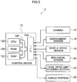
- FIG. 5 is a block drawing showing the schematic structure of a display device for a vehicle relating to the present embodiment. Note that portions that are the same as those of the first embodiment are denoted by the same reference numerals, and detailed description thereof is omitted.
- a display device 11 for a vehicle relating to the present embodiment differs from the first embodiment only with regard to the point that the display device 11 for a vehicle further includes a biological sensor 24.
- the biological sensor 24 is connected to the I/O 12D of the control device 12, and detects biometric information of a vehicle occupant, and outputs the results of detection of the control device 12.
- a heartbeat sensor, a respiration sensor, a perspiration sensor or the like can be used as the biological sensor 24, and at least one type of biometric information among heartbeat, respiration and perspiration is detected.
- the control device 12 detects the psychological state (e.g., the degree of excitation or the degree of calmness or the like) of the driver from the results of detection of the biological sensor 24.
- control device 12 detects the psychological state on the basis of the results of detection of the biological sensor 24, and, in accordance with the detected psychological state, changes the scrolling speeds of the first through fourth layers and displays images.
- the biological sensor 24 and the control device 12 correspond to the detecting portion.
- the control device 12 judges the psychological state of the driver (whether the driver is in an excited state, or whether the driver is in a calm state, or whether the driver is in a usual state), and carries out control so as to display the images on the display portion 22 at scrolling speeds that are set in advance in accordance with psychological states.
- the scrolling speeds that are set in advance in accordance with psychological states of a vehicle occupant are stored in advance in the ROM 12B or the like. As an example, as shown in Fig.
- the scrolling speed is -0.1 v for the first layer, -0.05 v for the second layer, -0.01 v for the third layer, and -0.002 v for the fourth layer. Further, at times when the vehicle occupant is excited, the scrolling speed is -0.05 v for the first layer, -0.025 v for the second layer, -0.005 v for the third layer, and -0.001 v for the fourth layer. At times when the vehicle occupant is calm, the scrolling speed is -0.2 v for the first layer, -0.1 v for the second layer, -0.02 v for the third layer, and -0.004 v for the fourth layer. In the present embodiment, when the vehicle occupant is excited, the scrolling speeds are made to be slower than the usual speeds. On the other hand, when the vehicle occupant is calm, the scrolling speeds are made to be faster than the usual speeds in order to obtain the appropriate level of excitement.
- Fig. 7 is a flowchart showing an example of the flow of display control that is carried out at the control device 12 of the display device 11 for a vehicle relating to the present embodiment. Note that the processings of Fig. 7 start, for example, in a case in which a display instruction is given by a switch for displaying images on the display portion 22 or the like, and the vehicle starts traveling. Further, processings that are the same as those of Fig. 4 are described by using the same reference numerals.
- step 100 the CPU 12A carries out image analysis on the captured image that has been captured by the camera 14, and the routine moves on to step 102.
- the CPU 12A carries out image analysis on the captured image, and detects the peripheral environment of the vehicle.
- the CPU 12A detects the peripheral environment by analyzing portions corresponding to the first through fourth layers from the captured image.
- step 102 the CPU 12A acquires the results of detection of the vehicle speed sensor 18 and detects the vehicle speed, and the routine moves on to step 104.
- step 104 the CPU 12A acquires information of the legal speed limit that was acquired by the legal speed limit acquiring section 20, and the routine moves on to step 106.
- the information of the legal speed limit may be acquired by, for example, extracting a speed limit sign from the image captured by the camera 14.
- information of the legal speed limit may be acquired from information that is included in map information of a navigation device.
- information of the legal speed limit may be acquired from infrastructures such as an information collecting/managing center or the like.
- step 106 on the basis of the acquired information of the legal speed limit, the CPU 12A judges whether or not the vehicle is traveling within the legal speed limit. If this judgment is affirmative, the routine moves on to step 108. If this judgment is negative, the routine moves on to step 114.
- step 108 the CPU 12A acquires the results of detection of the environment sensor 16, and the routine moves on to step 110.
- the CPU 12A acquires information, which relates to the environment, of an illuminance sensor, an outside air temperature sensor, a raindrop sensor, and the like.
- the CPU 12A specifies respective layers from among the predetermined first through fourth layers, and selects images that are to be displayed, and the routine moves on to step 111A.
- the CPU 12A selects image types of the respective layers such that there will become a scene that resembles the captured image. More concretely, in a case in which clear weather is specified from the captured image and the results of detection of the environment sensor 16 (the illuminance, the outside air temperature, the absence/presence of raindrops, and the like), the CPU 12A selects no image for the first layer.
- the CPU 12A selects the image of the group of buildings for the second layer. In a case in which clouds are detected from the captured image, the CPU 12A selects the image of the clouds for the third layer. Further, in a case in which daytime sky is detected from the captured image and the results of detection of the environment sensor 16, the CPU 12A selects the image of the daytime sky for the fourth layer.
- step 111 A by acquiring the results of detection of the biological sensor 24, the CPU 12A acquires biometric information of the vehicle occupant, and the routine moves on to step 111B.
- step 111B the CPU 12A determines the display speeds on the basis of the acquired biometric information, and the routine moves on to step 113. Namely, the CPU 12A specifies the psychological state of the vehicle occupant (whether the vehicle occupant is in a usual state, or whether the vehicle occupant is in an excited state, or whether the vehicle occupant is in a calm state) from the results of detection of the biological sensor 24, and determines the scrolling speeds of the respective layers of the image.
- a heartbeat sensor for example, by setting in advance a range of a normal number of heartbeats, a range of a number of heartbeats when excited, and a range of a number of heartbeats when calm, the CPU 12A judges which of the ranges the detected number of heartbeats is in. Due thereto, the CPU 12A specifies the psychological state of the vehicle occupant, and reads-out the corresponding scrolling speed.
- step 113 the CPU 12A carries out control so as to display the selected images on the display portion 22 such that the respective layers of the images move at the determined speeds, and the routine moves on to step 118. Due thereto, in a case in which the vehicle is traveling within the legal speed limit, images of the first through the fourth layers, which have been selected in accordance with the peripheral environment, are displayed on the display portion 22. Further, as shown in Fig. 3A , with respect to the scrolling speeds of the respective layers, the images of the respective layers are displayed so as to stream at speeds corresponding to the vehicle speed. In this way, when the vehicle is traveling within the legal speed limit, images that correspond to the peripheral environment are displayed on the ceiling, and therefore, an exhilarating feeling can be imparted to the vehicle occupant. Further, because the images are moved at display speeds that are set in advance in accordance with psychological states of the vehicle occupant, the vehicle occupant can be settled into a desirable psychological state.
- step 114 the CPU 12A judges whether or not images are currently being displayed on the display portion 22. In this judgment, it is judged whether or not above-described steps 108 through 112 have already been carried out, and images are being displayed on the display portion 22. If this judgment is affirmative, the routine moves on to step 116. If this judgment is negative, the routine moves on to step 118.
- step 116 the CPU 12A stops the images displayed on the display portion 22, and the routine moves on to step 118. Namely, in cases other than traveling within the legal speed limit, the display of the display portion 22 is stopped.
- step 118 the CPU 12A judges whether or not the display control is to be ended. This judgment may be carried out, for example, by judging whether or not a vehicle occupant has given a stop instruction by using the unillustrated switch or the like. Or, it may be judged whether or not traveling has ended and an unillustrated ignition switch has been turned off. If this judgment is negative, the routine returns to step 102, and the above-described processings are repeated. If this judgment is affirmative, the series of display control processings is ended.
- the psychological state of the vehicle occupant can be adjusted to a desirable psychological state. Therefore, the driver's concentration on driving can be improved, and the effect of decreasing traffic accidents can be expected.
- images may be displayed on the front windshield glass, the side window glasses, the rear windshield, the pillars, or the like.
- images may be displayed on the upper portion of the vehicle cabin interior (the ceiling, and the upper portions of the front windshield glass, the side window glasses, the rear windshield and the pillars).
- images are displayed on interior finishings or the like within the vehicle cabin.
- the processings that are carried out by the control device 12 in the above respective embodiments are software processings that are carried out by the execution of programs.
- the present disclosure is not limited to this.
- the processings may be processings that are carried out by hardware.
- the processings may be processings that combine both software and hardware.
- a program may be stored on any of various types of storage media and distributed.
Landscapes
- Engineering & Computer Science (AREA)
- Mechanical Engineering (AREA)
- Chemical & Material Sciences (AREA)
- Combustion & Propulsion (AREA)
- Transportation (AREA)
- Computer Hardware Design (AREA)
- Physics & Mathematics (AREA)
- General Physics & Mathematics (AREA)
- Theoretical Computer Science (AREA)
- Controls And Circuits For Display Device (AREA)
- Fittings On The Vehicle Exterior For Carrying Loads, And Devices For Holding Or Mounting Articles (AREA)
- Control Of Driving Devices And Active Controlling Of Vehicle (AREA)
- Instrument Panels (AREA)
- Multimedia (AREA)
Abstract
Description
- The present disclosure relates to a display device for a vehicle.
- As a display device for a vehicle, there is generally known a device that is disposed at an instrument panel or the like and displays various types of information, so that the driver can look at the various types of information while facing forward.
- The technique disclosed in Japanese Patent Application Laid-Open (
JP-A) No. 2016-215743 - The technique of Patent Document 1 proposes that all of the plural windows and the ceiling of a vehicle that can be driven automatically display various types of contents as touch-panel displays that can be operated by touch.
- However, in the technique disclosed in Patent Document 1, although various types of contents can be displayed, no contrivance has been made to make a vehicle occupant be able to drive comfortably, and therefore, there is room for improvement.
- The present disclosure was made in view of the above-described circumstances, and an object thereof is to provide a display device for a vehicle by which a vehicle occupant can easily obtain an exhilarating feeling that corresponds to the vehicle speed.
- In order to achieve the above-described object, an aspect includes: a display portion provided at a vehicle cabin interior; and a control section that, while a vehicle is traveling, carries out display control that displays, on the display portion, moving images that are based on vehicle speed and a peripheral environment of the vehicle.
- In accordance with the above-described aspect, the display portion is provided at the vehicle cabin interior. The display portion is provided, for example, at the upper portion of the vehicle cabin interior, or at the ceiling of the vehicle cabin interior.
- Further, while the vehicle is traveling, the control section carries out display control that displays, on the display portion, moving images that are based on the vehicle speed and the peripheral environment of the vehicle. In this way, due to moving images that are based on the vehicle speed and the peripheral environment being displayed on the display portion during traveling, the vehicle occupant can obtain an exhilarating feeling that corresponds to the vehicle speed.
- Note that the display device for a vehicle may further include a detecting portion that detects a psychological state of a driver (e.g., the degree of excitement or the degree of calmness or the like of the driver), wherein the control section may change display speeds of the moving images in accordance with the psychological state detected by the detecting portion. By detecting the psychological state of the driver and changing the display speeds of the moving images in this way, the driver is adjusted to an appropriate psychological state, which can contribute to safe driving.
- Further, the control section may carry out the display control in a case in which the vehicle is traveling within a legal speed limit. Namely, rendering that gives rise to an exhilarating feeling is carried out only at times when safe driving is being carried out. Therefore, both safe driving and an exhilarating feeling can be achieved, and the vehicle occupant can carry out stable driving by choice, and the effect of reducing dangerous driving and the number of traffic accidents can be expected.
- Further, by providing the display portion at the upper portion of the vehicle cabin interior or at the ceiling of the vehicle cabin interior, an exhilarating feeling that is as if the vehicle occupant is riding in a convertible can be rendered by the moving images.
- Moreover, the display portion may display images, which are formed from plural layers, as the moving images, and may display the moving images at speeds that are such that a display speed of each layer is different. Due thereto, rendering that is as if the actual landscape is streaming-by becomes possible.
- As described above, in accordance with the present disclosure, there is the effect that a display device for a vehicle, by which a vehicle occupant can easily obtain an exhilarating feeling that corresponds to the vehicle speed, can be provided.
-
-
Fig. 1 is a block drawing showing the schematic structure of a display device for a vehicle relating to a first embodiment. -
Fig. 2 is a drawing showing an example of displaying an image on a display portion that is provided at a ceiling. -
Fig. 3A is a table showing examples of scrolling speeds (display speeds of images) per stratum (layer) of the image displayed on the display portion, andFig. 3B is a table showing examples of types of images per layer that are displayed on the display portion. -
Fig. 4 is a flowchart showing an example of the flow of display control that is carried out at a control device of the display device for a vehicle relating to the present embodiment. -
Fig. 5 is a block drawing showing the schematic structure of a display device for a vehicle relating to a second embodiment. -
Fig. 6 is a table showing an example of scrolling speeds of respective layers that are determined in advance in accordance with the psychological state of the vehicle occupant. -
Fig. 7 is a flowchart showing an example of the flow of display control that is carried out at the control device of the display device for a vehicle relating to the present embodiment. - Examples of embodiments of the present disclosure are described in detail hereinafter with reference to the drawings.
-
Fig. 1 is a block drawing showing the schematic structure of a display device for a vehicle relating to the present embodiment. - As shown in
Fig. 1 , adisplay device 10 for a vehicle relating to the present embodiment has acamera 14, anenvironment sensor 16, avehicle speed sensor 18, a legal speedlimit acquiring section 20, adisplay portion 22, and acontrol device 12 that serves as a control section. - The
control device 12 is structured by a microcomputer at which a CPU (Central Processing Unit) 12A, a ROM (Read Only Memory) 12B, a RAM (Random Access Memory) 12C, and an I/O (input/output interface) 12D are respectively connected to abus 12E. - The
camera 14, theenvironment sensor 16, thevehicle speed sensor 18, the legal speedlimit acquiring section 20 and thedisplay portion 22 are connected to the I/O 12D. Further, a program for carrying out display control on thedisplay portion 22, and the like, are stored in theROM 12B of thecontrol device 12. TheRAM 12C is used as a work memory or the like for carrying out various types of computations and the like that are carried out by theCPU 12A. - The
camera 14 is provided in a vicinity of the inner rearview mirror for example, and captures images of the region in front of the vehicle, and outputs the results of imaging to thecontrol device 12. - The
environment sensor 16 detects information, which relates to the environment, of, for example, an illuminance sensor, an outside air temperature sensor, a raindrop sensor and the like, and outputs the results of detection to thecontrol device 12. Note that, instead of theenvironment sensor 16, there may be a form in which the results of detection of information relating to the environment are outputted to thecontrol device 12 from an air conditioning control device that controls the air conditioning of the vehicle, or the like. Further, either one of theenvironment sensor 16 or thecamera 14 may be omitted. - The
vehicle speed sensor 18 detects the traveling speed of the vehicle, and outputs the results of detection to thecontrol device 12. Note that, instead of thevehicle speed sensor 18, there may be a form in which vehicle speed information is outputted to thecontrol device 12 from a driving control device that controls the driving source of the vehicle such as the engine or the like, or the like. - The legal speed
limit acquiring section 20 acquires information of the legal speed limit, and outputs it to thecontrol device 12. The legal speedlimit acquiring section 20 may acquire information of the legal speed limit by, for example, extracting speed limit signs from the images captured by thecamera 14. Or, the legal speedlimit acquiring section 20 may acquire information of the legal speed limit from information that is included in map information of a navigation device. Or, the legal speedlimit acquiring section 20 may acquire information of the legal speed limit from infrastructures such as an information collecting/managing center that collects and manages information of ETCs (Electronic Toll Collection Systems), VICS (Vehicle Information & Communications Systems) or the like, or the like. - In the present embodiment, the
display portion 22 is provided at the ceiling of the vehicle cabin interior, and displays moving images that respectively correspond to the vehicle speed and the peripheral environment of the vehicle. For example, as shown inFig. 2 , moving images are displayed on the ceiling portion of the vehicle cabin interior. Thedisplay portion 22 may display the moving images from the lower side of the ceiling by a projector or the like, or a liquid crystal display or an organic EL (electroluminescent) display or the like may be provided at the ceiling and the moving images may be displayed thereon. - The
control device 12 carries out display control for displaying, on thedisplay portion 22, moving images that are based on the vehicle speed and the peripheral environment of the vehicle. - A concrete example of display control by the
control device 12 is explained here.Fig. 3A is a table showing examples of scrolling speeds (display speeds of images) per stratum (layer) of the image displayed on thedisplay portion 22.Fig. 3B is a table showing examples of types of images per layer that are displayed on thedisplay portion 22. - In the present embodiment, the
control device 12 carries out control to display, on thedisplay portion 22, images that are structured by plural layers. Further, thecontrol device 12 displays moving images on thedisplay portion 22 by moving the images at display speeds (scrolling speeds) that differ per layer. - For example, as shown in
Fig. 3A and Fig. 3B , images are classified into four types that are at a near distance (near), are at an intermediate distance (intermediate), are at a far distance (far) and are deep-back (deep-back), and the respective layers are determined in advance. Further, as shown inFig. 3A , the scrolling speed is determined in advance for each layer. In the example ofFig. 3A , given that the vehicle speed in the advancing direction of the vehicle is +v (km/h), the scrolling speed of the first layer is -0.1 v. Further, the scrolling speed of the second layer is -0.05 v, the scrolling speed of the third layer is -0.01 v, and the scrolling speed of the fourth layer is -0.002 v. In this way, rendering that is as if the actual landscape is streaming-by becomes possible by making it such that, the further away the image, the lower the scrolling speed. - As shown in
Fig. 3B for example, for each layer, predetermined types of images are set in advance respectively, and images are selected and displayed in accordance with the peripheral environment of the vehicle. In the example ofFig. 3B , flower petals, raindrops, autumn leaves, snow crystals and the like are set in advance for the first layer. Foliage, groups of buildings, lightning, streetlights and the like are set in advance for the second layer. Clouds, rainbows and the like are set in advance for the third layer. Evening sky, daytime sky, nighttime sky, darkness and the like are set in advance for the fourth layer. Note that there are cases in which the first through third layers are not displayed. - The
control device 12 detects the captured images that have been captured by thecamera 14 and the peripheral environment of the vehicle from the results of detection of theenvironment sensor 16, and selects image of layers corresponding to the peripheral environment that has been detected. For example, image types that become scenes that resemble the captured images and the information relating to the detected environment are selected per layer from the images types of the respective layers shown inFig. 3B . Then, the scrolling speeds of the respective layers are determined on the basis of the scrolling speeds shown inFig. 3A , from the vehicle speed detected by thevehicle speed sensor 18, and the images are displayed on thedisplay portion 22. - Further, the
control device 12 carries out the above-described display control in a case in which the vehicle speed detected by thevehicle speed sensor 18 is a speed that is within the legal speed limit acquired by the legal speedlimit acquiring section 20. - Due thereto, moving images that correspond to the vehicle speed and the peripheral environment of the vehicle are displayed on the
display portion 22, and an exhilarating feeling as if riding in a convertible can be presented. Further, because images are displayed on thedisplay portion 22 at times of traveling at speeds that are within the legal speed limit, the exhilarating rendering is carried out only at times when safe driving is being carried out, and both safe driving and an exhilarating feeling can be achieved. - Concrete processings, which are carried out at the
control device 12 of thedisplay device 10 for a vehicle relating to the present embodiment that is structured as described above, are described next.Fig. 4 is a flowchart showing an example of the flow of display control that is carried out at thecontrol device 12 of thedisplay device 10 for a vehicle relating to the present embodiment. Note that the processings ofFig. 4 start, for example, in a case in which a display instruction is given by a switch for displaying images on thedisplay portion 22 or the like, and the vehicle starts traveling. - In
step 100, theCPU 12A carries out image analysis on the captured image that has been captured by thecamera 14, and the routine moves on to step 102. Namely, theCPU 12A carries out image analysis on the captured image, and detects the peripheral environment of the vehicle. For example, theCPU 12A analyzes the captured image in order to determine the types of images of the first through fourth layers that are to be displayed on thedisplay portion 22, and detects the peripheral environment. - In
step 102, theCPU 12A acquires the results of detection of thevehicle speed sensor 18 and detects the vehicle speed, and the routine moves on to step 104. - In
step 104, theCPU 12A acquires information of the legal speed limit that was acquired by the legal speedlimit acquiring section 20, and the routine moves on to step 106. As described above, the information of the legal speed limit may be acquired by, for example, extracting a speed limit sign from the image captured by thecamera 14. Or, information of the legal speed limit may be acquired from information that is included in map information of a navigation device. Or, information of the legal speed limit may be acquired from infrastructures such as an information collecting/managing center or the like. - In
step 106, on the basis of the acquired information of the legal speed limit, theCPU 12A judges whether or not the vehicle is traveling within the legal speed limit. If this judgment is affirmative, the routine moves on to step 108. If this judgment is negative, the routine moves on to step 114. - In
step 108, theCPU 12A acquires the results of detection of theenvironment sensor 16, and the routine moves on to step 110. For example, theCPU 12A acquires information, which relates to the environment, of an illuminance sensor, an outside air temperature sensor, a raindrop sensor, and the like. - In
step 110, theCPU 12A specifies the respective layers from among the predetermined first through fourth layers, and selects images that are to be displayed, and the routine moves on to step 112. For example, on the basis of the image analysis of the image captured by thecamera 14 and the results of detection of theenvironment sensor 16, theCPU 12A selects image types of the respective layers such that there will become a scene that resembles the captured image. More concretely, in a case in which clear weather is specified from the captured image and the results of detection of the environment sensor 16 (the illuminance, the outside air temperature, the absence/presence of raindrops, and the like), theCPU 12A selects no image for the first layer. Further, in a case in which a group of buildings is detected from the captured image, theCPU 12A selects the image of the group of buildings for the second layer. In a case in which clouds are detected from the captured image, theCPU 12A selects the image of the clouds for the third layer. Further, in a case in which daytime sky is detected from the captured image and the results of detection of theenvironment sensor 16, theCPU 12A selects the image of the daytime sky for the fourth layer. - In
step 112, theCPU 12A carries out control so as to display the selected images on thedisplay portion 22, and the routine moves on to step 118. Due thereto, in a case in which the vehicle is traveling within the legal speed limit, images of the first through the fourth layers, which have been selected in accordance with the peripheral environment, are displayed on thedisplay portion 22. Further, as shown inFig. 3A , with respect to the scrolling speeds of the respective layers, the images of the respective layers are displayed so as to stream at speeds corresponding to the vehicle speed. For example, in the example of the selections of images described instep 110, the moving image shown inFig. 2 is displayed on thedisplay portion 22. In this way, when the vehicle is traveling within the legal speed limit, images that correspond to the peripheral environment are displayed on the ceiling, and therefore, an exhilarating feeling can be imparted to the vehicle occupants. - On the other hand, in
step 114, theCPU 12A judges whether or not images are currently being displayed on thedisplay portion 22. In this judgment, it is judged whether or not above-describedsteps 108 through 112 have already been carried out, and images are being displayed on thedisplay portion 22. If this judgment is affirmative, the routine moves on to step 116. If this judgment is negative, the routine moves on to step 118. - In
step 116, theCPU 12A stops the images displayed on thedisplay portion 22, and the routine moves on to step 118. Namely, in cases other than traveling within the legal speed limit, the display of thedisplay portion 22 is stopped. - In
step 118, theCPU 12A judges whether or not the display control is to be ended. This judgment may be carried out, for example, by judging whether or not a vehicle occupant has given a stop instruction by using the unillustrated switch or the like. Or, it may be judged whether or not traveling has ended and an unillustrated ignition switch has been turned off. If this judgment is negative, the routine returns to step 102, and the above-described processings are repeated. If this judgment is affirmative, the series of display control processings is ended. - In this way, in the present embodiment, when the vehicle is traveling within the legal speed limit, images that are based on the vehicle speed and the peripheral environment of the vehicle are displayed on the
display portion 22, and, due thereto, an exhilarating feeling can be presented by the images that are displayed on the ceiling. Further, because the images are displayed on thedisplay portion 22 only in cases in which the vehicle is traveling within the legal speed limit, rendering that gives rise to an exhilarating feeling is carried out only at times of safe driving. Therefore, both safe driving and an exhilarating feeling can be achieved, and the vehicle occupant carries out stable driving by choice, and the effect of reducing dangerous driving and the number of traffic accidents can be expected. - A display device for a vehicle relating to a second embodiment is described next.
Fig. 5 is a block drawing showing the schematic structure of a display device for a vehicle relating to the present embodiment. Note that portions that are the same as those of the first embodiment are denoted by the same reference numerals, and detailed description thereof is omitted. - As shown in
Fig. 5 , adisplay device 11 for a vehicle relating to the present embodiment differs from the first embodiment only with regard to the point that thedisplay device 11 for a vehicle further includes abiological sensor 24. - The
biological sensor 24 is connected to the I/O 12D of thecontrol device 12, and detects biometric information of a vehicle occupant, and outputs the results of detection of thecontrol device 12. For example, a heartbeat sensor, a respiration sensor, a perspiration sensor or the like can be used as thebiological sensor 24, and at least one type of biometric information among heartbeat, respiration and perspiration is detected. Thecontrol device 12 detects the psychological state (e.g., the degree of excitation or the degree of calmness or the like) of the driver from the results of detection of thebiological sensor 24. In the present embodiment, thecontrol device 12 detects the psychological state on the basis of the results of detection of thebiological sensor 24, and, in accordance with the detected psychological state, changes the scrolling speeds of the first through fourth layers and displays images. Note that, in the present embodiment, thebiological sensor 24 and thecontrol device 12 correspond to the detecting portion. - Concretely, for example, from the results of detection of the
biological sensor 24, thecontrol device 12 judges the psychological state of the driver (whether the driver is in an excited state, or whether the driver is in a calm state, or whether the driver is in a usual state), and carries out control so as to display the images on thedisplay portion 22 at scrolling speeds that are set in advance in accordance with psychological states. The scrolling speeds that are set in advance in accordance with psychological states of a vehicle occupant are stored in advance in theROM 12B or the like. As an example, as shown inFig. 6 , in the case of a usual speed, the scrolling speed is -0.1 v for the first layer, -0.05 v for the second layer, -0.01 v for the third layer, and -0.002 v for the fourth layer. Further, at times when the vehicle occupant is excited, the scrolling speed is -0.05 v for the first layer, -0.025 v for the second layer, -0.005 v for the third layer, and -0.001 v for the fourth layer. At times when the vehicle occupant is calm, the scrolling speed is -0.2 v for the first layer, -0.1 v for the second layer, -0.02 v for the third layer, and -0.004 v for the fourth layer. In the present embodiment, when the vehicle occupant is excited, the scrolling speeds are made to be slower than the usual speeds. On the other hand, when the vehicle occupant is calm, the scrolling speeds are made to be faster than the usual speeds in order to obtain the appropriate level of excitement. - Concrete processings, which are carried out at the
control device 12 of thedisplay device 11 for a vehicle relating to the present embodiment that is structured as described above, are described next.Fig. 7 is a flowchart showing an example of the flow of display control that is carried out at thecontrol device 12 of thedisplay device 11 for a vehicle relating to the present embodiment. Note that the processings ofFig. 7 start, for example, in a case in which a display instruction is given by a switch for displaying images on thedisplay portion 22 or the like, and the vehicle starts traveling. Further, processings that are the same as those ofFig. 4 are described by using the same reference numerals. - In
step 100, theCPU 12A carries out image analysis on the captured image that has been captured by thecamera 14, and the routine moves on to step 102. Namely, theCPU 12A carries out image analysis on the captured image, and detects the peripheral environment of the vehicle. For example, theCPU 12A detects the peripheral environment by analyzing portions corresponding to the first through fourth layers from the captured image. - In
step 102, theCPU 12A acquires the results of detection of thevehicle speed sensor 18 and detects the vehicle speed, and the routine moves on to step 104. - In
step 104, theCPU 12A acquires information of the legal speed limit that was acquired by the legal speedlimit acquiring section 20, and the routine moves on to step 106. As described above, the information of the legal speed limit may be acquired by, for example, extracting a speed limit sign from the image captured by thecamera 14. Or, information of the legal speed limit may be acquired from information that is included in map information of a navigation device. Or, information of the legal speed limit may be acquired from infrastructures such as an information collecting/managing center or the like. - In
step 106, on the basis of the acquired information of the legal speed limit, theCPU 12A judges whether or not the vehicle is traveling within the legal speed limit. If this judgment is affirmative, the routine moves on to step 108. If this judgment is negative, the routine moves on to step 114. - In
step 108, theCPU 12A acquires the results of detection of theenvironment sensor 16, and the routine moves on to step 110. For example, theCPU 12A acquires information, which relates to the environment, of an illuminance sensor, an outside air temperature sensor, a raindrop sensor, and the like. - In
step 110, theCPU 12A specifies respective layers from among the predetermined first through fourth layers, and selects images that are to be displayed, and the routine moves on to step 111A. For example, on the basis of the image analysis of the image captured by thecamera 14 and the results of detection of theenvironment sensor 16, theCPU 12A selects image types of the respective layers such that there will become a scene that resembles the captured image. More concretely, in a case in which clear weather is specified from the captured image and the results of detection of the environment sensor 16 (the illuminance, the outside air temperature, the absence/presence of raindrops, and the like), theCPU 12A selects no image for the first layer. Further, in a case in which a group of buildings is detected from the captured image, theCPU 12A selects the image of the group of buildings for the second layer. In a case in which clouds are detected from the captured image, theCPU 12A selects the image of the clouds for the third layer. Further, in a case in which daytime sky is detected from the captured image and the results of detection of theenvironment sensor 16, theCPU 12A selects the image of the daytime sky for the fourth layer. - In
step 111 A, by acquiring the results of detection of thebiological sensor 24, theCPU 12A acquires biometric information of the vehicle occupant, and the routine moves on to step 111B. - In
step 111B, theCPU 12A determines the display speeds on the basis of the acquired biometric information, and the routine moves on to step 113. Namely, theCPU 12A specifies the psychological state of the vehicle occupant (whether the vehicle occupant is in a usual state, or whether the vehicle occupant is in an excited state, or whether the vehicle occupant is in a calm state) from the results of detection of thebiological sensor 24, and determines the scrolling speeds of the respective layers of the image. For example, in a case in which a heartbeat sensor is used as the biological sensor, by setting in advance a range of a normal number of heartbeats, a range of a number of heartbeats when excited, and a range of a number of heartbeats when calm, theCPU 12A judges which of the ranges the detected number of heartbeats is in. Due thereto, theCPU 12A specifies the psychological state of the vehicle occupant, and reads-out the corresponding scrolling speed. - In
step 113, theCPU 12A carries out control so as to display the selected images on thedisplay portion 22 such that the respective layers of the images move at the determined speeds, and the routine moves on to step 118. Due thereto, in a case in which the vehicle is traveling within the legal speed limit, images of the first through the fourth layers, which have been selected in accordance with the peripheral environment, are displayed on thedisplay portion 22. Further, as shown inFig. 3A , with respect to the scrolling speeds of the respective layers, the images of the respective layers are displayed so as to stream at speeds corresponding to the vehicle speed. In this way, when the vehicle is traveling within the legal speed limit, images that correspond to the peripheral environment are displayed on the ceiling, and therefore, an exhilarating feeling can be imparted to the vehicle occupant. Further, because the images are moved at display speeds that are set in advance in accordance with psychological states of the vehicle occupant, the vehicle occupant can be settled into a desirable psychological state. - On the other hand, in
step 114, theCPU 12A judges whether or not images are currently being displayed on thedisplay portion 22. In this judgment, it is judged whether or not above-describedsteps 108 through 112 have already been carried out, and images are being displayed on thedisplay portion 22. If this judgment is affirmative, the routine moves on to step 116. If this judgment is negative, the routine moves on to step 118. - In
step 116, theCPU 12A stops the images displayed on thedisplay portion 22, and the routine moves on to step 118. Namely, in cases other than traveling within the legal speed limit, the display of thedisplay portion 22 is stopped. - In
step 118, theCPU 12A judges whether or not the display control is to be ended. This judgment may be carried out, for example, by judging whether or not a vehicle occupant has given a stop instruction by using the unillustrated switch or the like. Or, it may be judged whether or not traveling has ended and an unillustrated ignition switch has been turned off. If this judgment is negative, the routine returns to step 102, and the above-described processings are repeated. If this judgment is affirmative, the series of display control processings is ended. - In this way, in the present embodiment, as compared with the first embodiment, by changing the display speeds of the images in accordance with the psychological state of the vehicle occupant, the psychological state of the vehicle occupant can be adjusted to a desirable psychological state. Therefore, the driver's concentration on driving can be improved, and the effect of decreasing traffic accidents can be expected.
- Note that the above embodiments describe examples in which the
display portion 22 is provided at the ceiling, and images are displayed on the ceiling. However, the present disclosure is not limited to this. For example, images may be displayed on the front windshield glass, the side window glasses, the rear windshield, the pillars, or the like. Or, there may be a form in which images are displayed on the upper portion of the vehicle cabin interior (the ceiling, and the upper portions of the front windshield glass, the side window glasses, the rear windshield and the pillars). Or, there may be a form in which the images are displayed on interior finishings or the like within the vehicle cabin. - Further, description has been given in which the processings that are carried out by the
control device 12 in the above respective embodiments are software processings that are carried out by the execution of programs. However, the present disclosure is not limited to this. For example, the processings may be processings that are carried out by hardware. Or, the processings may be processings that combine both software and hardware. Further, when the processings are software processings, a program may be stored on any of various types of storage media and distributed. - Moreover, the present disclosure is not limited to the above, and, other than the above, can of course be implemented by being modified in various ways within a scope that does not depart from the gist thereof.
Claims (5)
- A display device (10) for a vehicle, comprising:a display portion (22) provided at a vehicle cabin interior; anda control section (12) configured, while a vehicle is traveling, to carry out display control that displays, on the display portion (22), moving images that are based on vehicle speed and a peripheral environment of the vehicle.
- The display device (10) for a vehicle of claim 1, further comprising a detecting portion (12) configured to detect a psychological state of a driver,
wherein the control section (12) is configured to change display speeds of the moving images in accordance with the psychological state detected by the detecting portion (12). - The display device (10) for a vehicle of claim 1 or claim 2, wherein the control section (12) is configured to carry out the display control in a case in which the vehicle is traveling within a legal speed limit.
- The display device (10) for a vehicle of any one of claims 1 through 3, wherein the display portion (22) is provided at an upper portion of the vehicle cabin interior, or at a ceiling of the vehicle cabin interior.
- The display device (10) for a vehicle of any one of claims 1 through 4, wherein the display portion (22) is configured to display images, which are formed from a plurality of layers, as the moving images, and to display the moving images at speeds that are such that a display speed of each layer is different.
Applications Claiming Priority (1)
| Application Number | Priority Date | Filing Date | Title |
|---|---|---|---|
| JP2017135048A JP2019014450A (en) | 2017-07-10 | 2017-07-10 | Display device for vehicle |
Publications (1)
| Publication Number | Publication Date |
|---|---|
| EP3427993A1 true EP3427993A1 (en) | 2019-01-16 |
Family
ID=62874804
Family Applications (1)
| Application Number | Title | Priority Date | Filing Date |
|---|---|---|---|
| EP18182296.6A Withdrawn EP3427993A1 (en) | 2017-07-10 | 2018-07-06 | Display device for vehicle |
Country Status (4)
| Country | Link |
|---|---|
| US (1) | US20190012985A1 (en) |
| EP (1) | EP3427993A1 (en) |
| JP (1) | JP2019014450A (en) |
| CN (1) | CN109229029A (en) |
Families Citing this family (5)
| Publication number | Priority date | Publication date | Assignee | Title |
|---|---|---|---|---|
| WO2020084405A1 (en) * | 2018-10-25 | 2020-04-30 | 株式会社半導体エネルギー研究所 | Information processing device |
| JP6825683B1 (en) * | 2019-12-02 | 2021-02-03 | トヨタ自動車株式会社 | Vehicle display control device, vehicle display device, vehicle display control method and program |
| CN111251996A (en) * | 2020-02-04 | 2020-06-09 | 吉利汽车研究院(宁波)有限公司 | Multimedia skylight system and vehicle |
| EP4112387A4 (en) * | 2020-02-28 | 2023-08-16 | Sony Group Corporation | IMAGE PROCESSING DEVICE, DISPLAY SYSTEM, IMAGE PROCESSING METHOD AND RECORDING MEDIA |
| FR3144093B1 (en) * | 2022-12-23 | 2026-01-30 | Valeo Comfort & Driving Assistance | Vehicle driver assistance system |
Citations (6)
| Publication number | Priority date | Publication date | Assignee | Title |
|---|---|---|---|---|
| US20080291032A1 (en) * | 2007-05-23 | 2008-11-27 | Toyota Engineering & Manufacturing North America, Inc. | System and method for reducing boredom while driving |
| EP2257065A1 (en) * | 2008-02-20 | 2010-12-01 | Clarion Co., Ltd. | Vehicle peripheral image display system |
| US8089512B2 (en) * | 2007-10-02 | 2012-01-03 | Aisin Aw Co., Ltd. | Driving support device, driving support method and computer program |
| US20130235351A1 (en) * | 2012-03-07 | 2013-09-12 | GM Global Technology Operations LLC | Virtual convertible tops, sunroofs, and back windows, and systems and methods for providing same |
| WO2016166160A1 (en) * | 2015-04-13 | 2016-10-20 | SEs Solutions GmbH | Virtual panoramic roof- or sunroof assembly |
| JP2016215743A (en) | 2015-05-18 | 2016-12-22 | 小島プレス工業株式会社 | Automobile |
Family Cites Families (6)
| Publication number | Priority date | Publication date | Assignee | Title |
|---|---|---|---|---|
| JP3747866B2 (en) * | 2002-03-05 | 2006-02-22 | 日産自動車株式会社 | Image processing apparatus for vehicle |
| JP2007265274A (en) * | 2006-03-29 | 2007-10-11 | Sendai Foundation For Applied Information Sciences | Physiological adaptive display device |
| US8018472B2 (en) * | 2006-06-08 | 2011-09-13 | Qualcomm Incorporated | Blending multiple display layers |
| JP4396712B2 (en) * | 2006-09-15 | 2010-01-13 | カシオ計算機株式会社 | Camera device, photographing control program, and photographing control method |
| WO2012133982A1 (en) * | 2011-03-25 | 2012-10-04 | 엘지전자 주식회사 | Image processing device and method for controlling image processing device |
| US9547173B2 (en) * | 2013-10-03 | 2017-01-17 | Honda Motor Co., Ltd. | System and method for dynamic in-vehicle virtual reality |
-
2017
- 2017-07-10 JP JP2017135048A patent/JP2019014450A/en not_active Withdrawn
-
2018
- 2018-06-26 US US16/018,925 patent/US20190012985A1/en not_active Abandoned
- 2018-06-27 CN CN201810679188.5A patent/CN109229029A/en active Pending
- 2018-07-06 EP EP18182296.6A patent/EP3427993A1/en not_active Withdrawn
Patent Citations (6)
| Publication number | Priority date | Publication date | Assignee | Title |
|---|---|---|---|---|
| US20080291032A1 (en) * | 2007-05-23 | 2008-11-27 | Toyota Engineering & Manufacturing North America, Inc. | System and method for reducing boredom while driving |
| US8089512B2 (en) * | 2007-10-02 | 2012-01-03 | Aisin Aw Co., Ltd. | Driving support device, driving support method and computer program |
| EP2257065A1 (en) * | 2008-02-20 | 2010-12-01 | Clarion Co., Ltd. | Vehicle peripheral image display system |
| US20130235351A1 (en) * | 2012-03-07 | 2013-09-12 | GM Global Technology Operations LLC | Virtual convertible tops, sunroofs, and back windows, and systems and methods for providing same |
| WO2016166160A1 (en) * | 2015-04-13 | 2016-10-20 | SEs Solutions GmbH | Virtual panoramic roof- or sunroof assembly |
| JP2016215743A (en) | 2015-05-18 | 2016-12-22 | 小島プレス工業株式会社 | Automobile |
Also Published As
| Publication number | Publication date |
|---|---|
| CN109229029A (en) | 2019-01-18 |
| US20190012985A1 (en) | 2019-01-10 |
| JP2019014450A (en) | 2019-01-31 |
Similar Documents
| Publication | Publication Date | Title |
|---|---|---|
| EP3427993A1 (en) | Display device for vehicle | |
| KR102046468B1 (en) | Side mirror for vehicle | |
| US8733938B2 (en) | Virtual convertible tops, sunroofs, and back windows, and systems and methods for providing same | |
| EP3383690B1 (en) | Responsive human machine interface | |
| US11731509B2 (en) | Method for displaying the course of a trajectory in front of a transportation vehicle or an object by a display unit, and device for carrying out the method | |
| US20190361233A1 (en) | Vehicle display control device | |
| JP6460019B2 (en) | Vehicle control device | |
| US20140320946A1 (en) | Dynamically Managing Vehicle Glass Dimming | |
| JP2010072365A (en) | Head up display | |
| CN115210099B (en) | Information processing devices, vehicles and information processing methods | |
| KR20080020956A (en) | How to operate a night-view system of a vehicle and the corresponding night-view system | |
| WO2013088511A1 (en) | Display device, display method, head-up display, and detection device | |
| CN111032413A (en) | Method for operating a screen of a motor vehicle and motor vehicle | |
| JP4932067B1 (en) | Display device, display method, and display program | |
| JP2007076452A (en) | Vehicle anti-glare device and program | |
| JPH07266923A (en) | Vehicle display | |
| CN112677740A (en) | Apparatus and method for treating a windshield to make it invisible | |
| CN117334140A (en) | Display control method, display system and vehicle for front glass of vehicle | |
| JP2017202721A (en) | Display system | |
| JP2022041245A (en) | Vehicle display control device, method, program, and vehicle display system | |
| CN207328275U (en) | Drive assist system | |
| CN111216636A (en) | Travel control device, control method, and storage medium storing program | |
| JP2010125893A (en) | Night view video and speedometer display | |
| JP2009032190A (en) | Vehicle driver state detection device | |
| JP6658358B2 (en) | Vehicle control device |
Legal Events
| Date | Code | Title | Description |
|---|---|---|---|
| PUAI | Public reference made under article 153(3) epc to a published international application that has entered the european phase |
Free format text: ORIGINAL CODE: 0009012 |
|
| STAA | Information on the status of an ep patent application or granted ep patent |
Free format text: STATUS: REQUEST FOR EXAMINATION WAS MADE |
|
| 17P | Request for examination filed |
Effective date: 20180706 |
|
| AK | Designated contracting states |
Kind code of ref document: A1 Designated state(s): AL AT BE BG CH CY CZ DE DK EE ES FI FR GB GR HR HU IE IS IT LI LT LU LV MC MK MT NL NO PL PT RO RS SE SI SK SM TR |
|
| AX | Request for extension of the european patent |
Extension state: BA ME |
|
| STAA | Information on the status of an ep patent application or granted ep patent |
Free format text: STATUS: EXAMINATION IS IN PROGRESS |
|
| 17Q | First examination report despatched |
Effective date: 20191213 |
|
| STAA | Information on the status of an ep patent application or granted ep patent |
Free format text: STATUS: THE APPLICATION IS DEEMED TO BE WITHDRAWN |
|
| 18D | Application deemed to be withdrawn |
Effective date: 20200603 |