EP3427927A1 - Composite joint assembly - Google Patents
Composite joint assembly Download PDFInfo
- Publication number
- EP3427927A1 EP3427927A1 EP18183005.0A EP18183005A EP3427927A1 EP 3427927 A1 EP3427927 A1 EP 3427927A1 EP 18183005 A EP18183005 A EP 18183005A EP 3427927 A1 EP3427927 A1 EP 3427927A1
- Authority
- EP
- European Patent Office
- Prior art keywords
- end portion
- composite tube
- support wedge
- radially inward
- various embodiments
- Prior art date
- Legal status (The legal status is an assumption and is not a legal conclusion. Google has not performed a legal analysis and makes no representation as to the accuracy of the status listed.)
- Granted
Links
Images



Classifications
-
- F—MECHANICAL ENGINEERING; LIGHTING; HEATING; WEAPONS; BLASTING
- F16—ENGINEERING ELEMENTS AND UNITS; GENERAL MEASURES FOR PRODUCING AND MAINTAINING EFFECTIVE FUNCTIONING OF MACHINES OR INSTALLATIONS; THERMAL INSULATION IN GENERAL
- F16C—SHAFTS; FLEXIBLE SHAFTS; ELEMENTS OR CRANKSHAFT MECHANISMS; ROTARY BODIES OTHER THAN GEARING ELEMENTS; BEARINGS
- F16C3/00—Shafts; Axles; Cranks; Eccentrics
- F16C3/02—Shafts; Axles
- F16C3/026—Shafts made of fibre reinforced resin
-
- B—PERFORMING OPERATIONS; TRANSPORTING
- B29—WORKING OF PLASTICS; WORKING OF SUBSTANCES IN A PLASTIC STATE IN GENERAL
- B29C—SHAPING OR JOINING OF PLASTICS; SHAPING OF MATERIAL IN A PLASTIC STATE, NOT OTHERWISE PROVIDED FOR; AFTER-TREATMENT OF THE SHAPED PRODUCTS, e.g. REPAIRING
- B29C65/00—Joining or sealing of preformed parts, e.g. welding of plastics materials; Apparatus therefor
- B29C65/56—Joining or sealing of preformed parts, e.g. welding of plastics materials; Apparatus therefor using mechanical means or mechanical connections, e.g. form-fits
-
- B—PERFORMING OPERATIONS; TRANSPORTING
- B29—WORKING OF PLASTICS; WORKING OF SUBSTANCES IN A PLASTIC STATE IN GENERAL
- B29C—SHAPING OR JOINING OF PLASTICS; SHAPING OF MATERIAL IN A PLASTIC STATE, NOT OTHERWISE PROVIDED FOR; AFTER-TREATMENT OF THE SHAPED PRODUCTS, e.g. REPAIRING
- B29C66/00—General aspects of processes or apparatus for joining preformed parts
- B29C66/01—General aspects dealing with the joint area or with the area to be joined
- B29C66/05—Particular design of joint configurations
- B29C66/10—Particular design of joint configurations particular design of the joint cross-sections
- B29C66/11—Joint cross-sections comprising a single joint-segment, i.e. one of the parts to be joined comprising a single joint-segment in the joint cross-section
- B29C66/116—Single bevelled joints, i.e. one of the parts to be joined being bevelled in the joint area
- B29C66/1162—Single bevel to bevel joints, e.g. mitre joints
-
- B—PERFORMING OPERATIONS; TRANSPORTING
- B29—WORKING OF PLASTICS; WORKING OF SUBSTANCES IN A PLASTIC STATE IN GENERAL
- B29C—SHAPING OR JOINING OF PLASTICS; SHAPING OF MATERIAL IN A PLASTIC STATE, NOT OTHERWISE PROVIDED FOR; AFTER-TREATMENT OF THE SHAPED PRODUCTS, e.g. REPAIRING
- B29C66/00—General aspects of processes or apparatus for joining preformed parts
- B29C66/01—General aspects dealing with the joint area or with the area to be joined
- B29C66/05—Particular design of joint configurations
- B29C66/10—Particular design of joint configurations particular design of the joint cross-sections
- B29C66/12—Joint cross-sections combining only two joint-segments; Tongue and groove joints; Tenon and mortise joints; Stepped joint cross-sections
- B29C66/126—Tenon and mortise joints
-
- B—PERFORMING OPERATIONS; TRANSPORTING
- B29—WORKING OF PLASTICS; WORKING OF SUBSTANCES IN A PLASTIC STATE IN GENERAL
- B29C—SHAPING OR JOINING OF PLASTICS; SHAPING OF MATERIAL IN A PLASTIC STATE, NOT OTHERWISE PROVIDED FOR; AFTER-TREATMENT OF THE SHAPED PRODUCTS, e.g. REPAIRING
- B29C66/00—General aspects of processes or apparatus for joining preformed parts
- B29C66/50—General aspects of joining tubular articles; General aspects of joining long products, i.e. bars or profiled elements; General aspects of joining single elements to tubular articles, hollow articles or bars; General aspects of joining several hollow-preforms to form hollow or tubular articles
- B29C66/51—Joining tubular articles, profiled elements or bars; Joining single elements to tubular articles, hollow articles or bars; Joining several hollow-preforms to form hollow or tubular articles
- B29C66/52—Joining tubular articles, bars or profiled elements
- B29C66/526—Joining bars
-
- B—PERFORMING OPERATIONS; TRANSPORTING
- B29—WORKING OF PLASTICS; WORKING OF SUBSTANCES IN A PLASTIC STATE IN GENERAL
- B29C—SHAPING OR JOINING OF PLASTICS; SHAPING OF MATERIAL IN A PLASTIC STATE, NOT OTHERWISE PROVIDED FOR; AFTER-TREATMENT OF THE SHAPED PRODUCTS, e.g. REPAIRING
- B29C66/00—General aspects of processes or apparatus for joining preformed parts
- B29C66/50—General aspects of joining tubular articles; General aspects of joining long products, i.e. bars or profiled elements; General aspects of joining single elements to tubular articles, hollow articles or bars; General aspects of joining several hollow-preforms to form hollow or tubular articles
- B29C66/51—Joining tubular articles, profiled elements or bars; Joining single elements to tubular articles, hollow articles or bars; Joining several hollow-preforms to form hollow or tubular articles
- B29C66/53—Joining single elements to tubular articles, hollow articles or bars
- B29C66/534—Joining single elements to open ends of tubular or hollow articles or to the ends of bars
-
- B—PERFORMING OPERATIONS; TRANSPORTING
- B29—WORKING OF PLASTICS; WORKING OF SUBSTANCES IN A PLASTIC STATE IN GENERAL
- B29C—SHAPING OR JOINING OF PLASTICS; SHAPING OF MATERIAL IN A PLASTIC STATE, NOT OTHERWISE PROVIDED FOR; AFTER-TREATMENT OF THE SHAPED PRODUCTS, e.g. REPAIRING
- B29C66/00—General aspects of processes or apparatus for joining preformed parts
- B29C66/50—General aspects of joining tubular articles; General aspects of joining long products, i.e. bars or profiled elements; General aspects of joining single elements to tubular articles, hollow articles or bars; General aspects of joining several hollow-preforms to form hollow or tubular articles
- B29C66/51—Joining tubular articles, profiled elements or bars; Joining single elements to tubular articles, hollow articles or bars; Joining several hollow-preforms to form hollow or tubular articles
- B29C66/53—Joining single elements to tubular articles, hollow articles or bars
- B29C66/534—Joining single elements to open ends of tubular or hollow articles or to the ends of bars
- B29C66/5344—Joining single elements to open ends of tubular or hollow articles or to the ends of bars said single elements being substantially annular, i.e. of finite length, e.g. joining flanges to tube ends
-
- B—PERFORMING OPERATIONS; TRANSPORTING
- B29—WORKING OF PLASTICS; WORKING OF SUBSTANCES IN A PLASTIC STATE IN GENERAL
- B29C—SHAPING OR JOINING OF PLASTICS; SHAPING OF MATERIAL IN A PLASTIC STATE, NOT OTHERWISE PROVIDED FOR; AFTER-TREATMENT OF THE SHAPED PRODUCTS, e.g. REPAIRING
- B29C66/00—General aspects of processes or apparatus for joining preformed parts
- B29C66/70—General aspects of processes or apparatus for joining preformed parts characterised by the composition, physical properties or the structure of the material of the parts to be joined; Joining with non-plastics material
- B29C66/72—General aspects of processes or apparatus for joining preformed parts characterised by the composition, physical properties or the structure of the material of the parts to be joined; Joining with non-plastics material characterised by the structure of the material of the parts to be joined
- B29C66/721—Fibre-reinforced materials
-
- F—MECHANICAL ENGINEERING; LIGHTING; HEATING; WEAPONS; BLASTING
- F16—ENGINEERING ELEMENTS AND UNITS; GENERAL MEASURES FOR PRODUCING AND MAINTAINING EFFECTIVE FUNCTIONING OF MACHINES OR INSTALLATIONS; THERMAL INSULATION IN GENERAL
- F16D—COUPLINGS FOR TRANSMITTING ROTATION; CLUTCHES; BRAKES
- F16D1/00—Couplings for rigidly connecting two coaxial shafts or other movable machine elements
- F16D1/10—Quick-acting couplings in which the parts are connected by simply bringing them together axially
- F16D1/108—Quick-acting couplings in which the parts are connected by simply bringing them together axially having retaining means rotating with the coupling and acting by interengaging parts, i.e. positive coupling
-
- B—PERFORMING OPERATIONS; TRANSPORTING
- B29—WORKING OF PLASTICS; WORKING OF SUBSTANCES IN A PLASTIC STATE IN GENERAL
- B29L—INDEXING SCHEME ASSOCIATED WITH SUBCLASS B29C, RELATING TO PARTICULAR ARTICLES
- B29L2031/00—Other particular articles
- B29L2031/06—Rods, e.g. connecting rods, rails, stakes
-
- B—PERFORMING OPERATIONS; TRANSPORTING
- B29—WORKING OF PLASTICS; WORKING OF SUBSTANCES IN A PLASTIC STATE IN GENERAL
- B29L—INDEXING SCHEME ASSOCIATED WITH SUBCLASS B29C, RELATING TO PARTICULAR ARTICLES
- B29L2031/00—Other particular articles
- B29L2031/30—Vehicles, e.g. ships or aircraft, or body parts thereof
- B29L2031/3076—Aircrafts
-
- F—MECHANICAL ENGINEERING; LIGHTING; HEATING; WEAPONS; BLASTING
- F16—ENGINEERING ELEMENTS AND UNITS; GENERAL MEASURES FOR PRODUCING AND MAINTAINING EFFECTIVE FUNCTIONING OF MACHINES OR INSTALLATIONS; THERMAL INSULATION IN GENERAL
- F16B—DEVICES FOR FASTENING OR SECURING CONSTRUCTIONAL ELEMENTS OR MACHINE PARTS TOGETHER, e.g. NAILS, BOLTS, CIRCLIPS, CLAMPS, CLIPS OR WEDGES; JOINTS OR JOINTING
- F16B7/00—Connections of rods or tubes, e.g. of non-circular section, mutually, including resilient connections
- F16B7/02—Connections of rods or tubes, e.g. of non-circular section, mutually, including resilient connections with conical parts
-
- F—MECHANICAL ENGINEERING; LIGHTING; HEATING; WEAPONS; BLASTING
- F16—ENGINEERING ELEMENTS AND UNITS; GENERAL MEASURES FOR PRODUCING AND MAINTAINING EFFECTIVE FUNCTIONING OF MACHINES OR INSTALLATIONS; THERMAL INSULATION IN GENERAL
- F16C—SHAFTS; FLEXIBLE SHAFTS; ELEMENTS OR CRANKSHAFT MECHANISMS; ROTARY BODIES OTHER THAN GEARING ELEMENTS; BEARINGS
- F16C2208/00—Plastics; Synthetic resins, e.g. rubbers
- F16C2208/02—Plastics; Synthetic resins, e.g. rubbers comprising fillers, fibres
-
- F—MECHANICAL ENGINEERING; LIGHTING; HEATING; WEAPONS; BLASTING
- F16—ENGINEERING ELEMENTS AND UNITS; GENERAL MEASURES FOR PRODUCING AND MAINTAINING EFFECTIVE FUNCTIONING OF MACHINES OR INSTALLATIONS; THERMAL INSULATION IN GENERAL
- F16C—SHAFTS; FLEXIBLE SHAFTS; ELEMENTS OR CRANKSHAFT MECHANISMS; ROTARY BODIES OTHER THAN GEARING ELEMENTS; BEARINGS
- F16C2208/00—Plastics; Synthetic resins, e.g. rubbers
- F16C2208/20—Thermoplastic resins
- F16C2208/58—Several materials as provided for in F16C2208/30 - F16C2208/54 mentioned as option
-
- F—MECHANICAL ENGINEERING; LIGHTING; HEATING; WEAPONS; BLASTING
- F16—ENGINEERING ELEMENTS AND UNITS; GENERAL MEASURES FOR PRODUCING AND MAINTAINING EFFECTIVE FUNCTIONING OF MACHINES OR INSTALLATIONS; THERMAL INSULATION IN GENERAL
- F16C—SHAFTS; FLEXIBLE SHAFTS; ELEMENTS OR CRANKSHAFT MECHANISMS; ROTARY BODIES OTHER THAN GEARING ELEMENTS; BEARINGS
- F16C2208/00—Plastics; Synthetic resins, e.g. rubbers
- F16C2208/80—Thermosetting resins
- F16C2208/86—Epoxy resins
-
- F—MECHANICAL ENGINEERING; LIGHTING; HEATING; WEAPONS; BLASTING
- F16—ENGINEERING ELEMENTS AND UNITS; GENERAL MEASURES FOR PRODUCING AND MAINTAINING EFFECTIVE FUNCTIONING OF MACHINES OR INSTALLATIONS; THERMAL INSULATION IN GENERAL
- F16C—SHAFTS; FLEXIBLE SHAFTS; ELEMENTS OR CRANKSHAFT MECHANISMS; ROTARY BODIES OTHER THAN GEARING ELEMENTS; BEARINGS
- F16C2226/00—Joining parts; Fastening; Assembling or mounting parts
- F16C2226/50—Positive connections
- F16C2226/80—Positive connections with splines, serrations or similar profiles to prevent movement between joined parts
-
- F—MECHANICAL ENGINEERING; LIGHTING; HEATING; WEAPONS; BLASTING
- F16—ENGINEERING ELEMENTS AND UNITS; GENERAL MEASURES FOR PRODUCING AND MAINTAINING EFFECTIVE FUNCTIONING OF MACHINES OR INSTALLATIONS; THERMAL INSULATION IN GENERAL
- F16C—SHAFTS; FLEXIBLE SHAFTS; ELEMENTS OR CRANKSHAFT MECHANISMS; ROTARY BODIES OTHER THAN GEARING ELEMENTS; BEARINGS
- F16C2326/00—Articles relating to transporting
- F16C2326/43—Aeroplanes; Helicopters
Definitions
- the present disclosure relates generally to composite joints and more specifically to improving load transfer via composite joints.
- actuators including, for example, to deploy nose, body, and/or wing landing gear systems.
- Conventional actuator components are made of metallic materials and often comprise complex geometries and high strengths. However, these metallic components are typically heavy.
- PMC fiber-reinforced polymer-matrix composites
- the present disclosure provides a composite tube that includes a body and an end portion.
- the body has a longitudinal centerline axis and the end portion has a tapered section terminating at an end rim, according to various embodiments.
- At least one of a radially outward edge of the end rim and a radially inward edge of the end rim is non-circular, according to various embodiments.
- the end rim is circumferentially continuous. In various embodiments, the end rim is an undulating annulus. In various embodiments, at least one of the radially outward edge and the radially inward edge of the end rim comprises an undulating wave-like shape.
- the tapered section includes a plurality of folds that form circumferentially distributed grooves extending along the tapered section. In various embodiments, the tapered section converges radially inward in a direction from the body to the end rim.
- the body of the composite tube may have a circular cross-section.
- the joint assembly may include a composite tube and a support wedge.
- the composite tube has a body and an end portion, according to various embodiments.
- the body may have a longitudinal centerline axis and the end portion may have an end rim that is circumferentially continuous.
- at least one of a radially outward edge and a radially inward edge of the end rim is non-circular.
- the support wedge may at least partially engage at least one of a radially inward surface of the end portion and a radially outward surface of the end portion.
- the end portion of the composite tube includes a tapered section that converges radially inward in a direction from the body to the end rim.
- the radially inward surface and the radially outward surface are walls of the tapered section of the end portion.
- the tapered section includes a plurality of folds that form circumferentially distributed grooves extending along the tapered section.
- the support wedge may have contours that complement the circumferentially distributed grooves of the tapered section.
- the end rim is an undulating annulus.
- At least one of the radially inward surface and the radially outward surface includes a plurality of folds that form circumferentially distributed grooves.
- the support wedge may be a first support wedge and the joint assembly may further include a second support wedge that engages the other of the radially inward surface and the radially outward surface.
- the first support wedge is an external support wedge that has an annular structure that is concentric with the longitudinal centerline axis and that circumscribes the end portion of the composite tube.
- the method may include forming an end portion of a composite tube.
- the end portion may include an end rim and at least one of a radially outward edge and a radially inward edge of the end rim may be non-circular.
- the method may further include engaging a support wedge to the end portion of the composite tube such that the support wedge includes contours that complement the end portion.
- the method further includes, after engaging the support wedge to the end portion of the composite tube, curing the composite tube (e.g., when using a thermoset matrix) or solidifying the composite tube (e.g., when using a thermoplastic matrix).
- forming the end portion includes tapering the end portion of the composite tube to form a tapered section that converges radially inward in a direction from the body to the end rim.
- forming the end portion includes shaping the end portion to have a plurality of folds that form circumferentially distributed grooves along at least one of radially inward surface and a radially outward surface of the end portion. Shaping the end portion may include using the support wedge as a mold.
- the support wedge is an internal support wedge and the method further includes engaging an annular external support wedge to the end portion.
- the present disclosure describes composite tubes and composite joint assemblies.
- the present disclosure relates to connecting composite tubes to other components via a composite joint assembly (e.g., "joints").
- a composite joint assembly e.g., "joints”
- Such joints may be used in aircraft systems, such as, for example, landing gear systems.
- the systems and methods of the present disclosure may be suitable for use in non-aircraft systems as well.
- axial refers to a position or direction along a longitudinal centerline axis of a composite tube.
- radial refers to a position or direction away from the longitudinal centerline axis of the composite tube.
- a first component that is "radially inward" of a second component means that the first component is positioned closer to the longitudinal centerline axis of the composite tube than the second component.
- PMC fiber-reinforced polymer-matrix composites
- the present disclosure relates to improving joint strength of composite joint assemblies.
- a composite tube 100 is illustrated having a body 110 and an end portion 120.
- the end portion 120 includes a tapered section 122 and an end rim 124.
- the end rim 124 is bound by a radially outward edge 126 and a radially inward edge 128.
- at least one of the radially outward edge 126 and the radially inward edge 128 is non-circular.
- the end rim 124 may be circumferentially continuous and thus may be a non-circular annulus.
- non-circular annulus means a ring-like shape that has an inner border that is non-circular and/or an outer border that is non-circular.
- the radially outward edge 126 and/or the radially inward edge 128 of the end rim 124 may have an undulating, wave-like ring shape.
- the body 110 of the composite tube 100 defines a hollow chamber extending along the longitudinal centerline axis 102.
- the body 110 of the composite tube 100 may by cylindrical and thus may have a circular cross-sectional shape.
- the shape of the end portion 120 e.g., the non-circular end rim 1214 may be different than the cross-sectional shape of the body 110, which may improve the torsional load transfer capabilities of the composite tube 100 when implemented in a joint assembly, as described in greater detail below.
- Also contributing to the load transfer capabilities of the composite tube 100 is the tapering shape of the end portion 120.
- the end portion 120 converges radially inward in a direction from the body 110 towards the end rim 124.
- the tapered section 122 may have a quasi-conical shape. Stated differently, the tapered section 122 may have a converging, cone-like shape but the "walls" of the cone-like shape may be circumferentially undulating, thus forming fold-like contours into the walls of the tapered section 122.
- the tapered section 122 of the end portion 120 has a plurality of folds that form circumferentially distributed grooves 125 extending along the tapered section 122.
- the folds/grooves 125 may extend along the entire length of the tapered section 122, the grooves 125 may be shorter than the tapered section 122, or the grooves 125 may be longer than the tapered section 122.
- the tapered section 122 has a non-circular cross-section, which may be similar to the shape of the end rim 124. Said differently, at least one of a radially inward surface 123 and a radially outward surface 121 of the end portion 120 (e.g., the tapered section 122 of the end portion 120) may have contours, grooves, channels, etc., that impart a non-circular cross-sectional shape to the end portion 120 of the composite tube 100.
- the folds/grooves 125 are smooth curves that may be free of sharp or abrupt directional changes.
- the folds/grooves 125 may be formed by crimping and/or clamping an uncured composite tube.
- the composite tube 100 may be a polymer-matrix composite (e.g., a fiber-reinforced polymer or a polymer without fiber reinforcement).
- the composite tube 100 is made from a carbon fiber composite material or a glass fiber composite material or organic fiber reinforced composite materials or a combination thereof.
- the weight, strength, and stiffness of composite tubes may be dictated by fiber type, fiber stiffness, fiber strength, fiber direction/placement, resin system used, and other parameters of the composite lay-up.
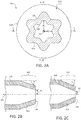
- FIG. 2A An end view of the end portion 120 of the composite tube 100, according to various embodiments, is provided in FIG. 2A .
- the end rim 124 of the end portion 120 may have an undulating shape and thus the radius, relative to the longitudinal centerline axis 102, of the opening defined by the end rim 124 may vary.
- inner radial dimension R1 may be greater than inner radial dimension R2.
- the radial distance between the longitudinal centerline axis 102 and the radially inward edge 128 of the end rim 124 may vary.
- the radial distance between the longitudinal centerline axis 102 and the radially outward edge 126 of the end rim 124 may vary.
- the wave-like end rim 124 includes waves that have uniform shapes and curvatures. In various embodiments, however, the wave-like end rim 124 includes wave sections that are not uniform with each other and thus have different shapes and curvatures. In various embodiments, the number of waves may be different than what is shown in the figures. In various embodiments, the number of waves is at least one. In various embodiments, the number of waves is 2 or more. For example, in various embodiments, the number of waves is between 3 and 6.
- FIG. 2B is a side view of the composite tube 100 of FIG. 2A from viewpoint "B" in FIG. 2A
- FIG. 2C is a side view of the composite tube 100 of FIG. 2A from viewpoint "C” in FIG. 2A
- " ⁇ " is the angle between the longitudinal centerline axis 102 of the body 110 of the composite tube 100 and the tapered section 122 that forms the end portion 120.
- ⁇ refers to the bend angle of either external or internal surfaces of the tapered section 122 of the end portion 120 relative to the body 110.
- ⁇ 1 in FIG. 2B which corresponds with R1
- ⁇ 2 in FIG. 2C which corresponds with R2.
- bend angle ⁇ may be between 0 degrees and 60 degrees.
- the bend angle ⁇ may be selected according to the specifics of a given application/configuration (e.g., depending on an expected/anticipated load transfer).
- a joint assembly 105 is provided.
- the joint assembly 105 includes the composite tube 100 coupled to one or more support wedges 132, 134.
- at least one support wedge 132, 134 may at least partially engage at least one of the radially inward surface 123 and the radially outward surface 121 of the end portion 120 of the composite tube 100 (though in FIG. 3 the wedge(s) 132, 134 are shown removed from the respective surfaces 121, 123 of the end portion 120, in practice the wedge(s) 132, 134 are contacting the respective surfaces 121, 123 of the end portion 120).
- engagement between the support wedge(s) and the end portion 120 is direct contact.
- the direct contact may be enhanced by pre-stress where the end portion and the support wedge(s) are mutually compressed during assembly of the joint and/or during service.
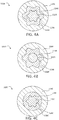
- the support wedge(s) 132, 134 may have contours that complement the non-circular shape of the end portion 120 of the composite tube 100, as described in greater detail below with reference to FIGS. 4A, 4B, and 4C .
- the support wedge(s) 132, 134 are made from a metallic material.
- the support wedge(s) 132, 134 may be made from other materials, such as fiber-reinforced PMC, and/or ceramic materials, among others.
- the support wedge(s) 132, 134 may be held against (e.g., engaged with) the end portion 120 by applying mechanical force, for example by threaded retraction of mechanical wedge 132 with respect to stationary wedge 134, or vice versa, or other similar attachment means.
- the process of curing the composite tube 100 bonds the support wedge 132, 134 to the composite tube 100.
- adhesives, resins, or bonding agents may be utilized to bond the support wedge(s) 132, 134 to the composite tube 100.
- the joint assembly 105 may include a first support wedge 132 and a second support wedge 134.
- the first support wedge 132 may be an internal support wedge 132 and thus may be inserted within the opening defined by the end rim 124 formed by converging tapered section 122 of the end portion 120 of the composite tube 100 to engage a radially inward surface 123 of the end potion 120.
- the second support wedge 134 may be an annular external support wedge 134 that is disposed about and substantially circumscribes the end portion 120 to engage a radially outward surface 121 of the end potion 120.
- Joint assembly 105A includes an end rim 124A that has both a non-circular radially outward edge 126A and a non-circular radially inward edge 128A, according to various embodiments.
- the internal support wedge 132A may be contoured to complement the radially inward surface 123 ( FIG. 3 ) of the end portion 120 of the composite tube 100 and the annular external support wedge 134A may be contoured to complement the radially outward surface 121 ( FIG. 3 ) of the end portion 120 of the composite tube 100.
- Joint assembly 105B includes an end rim 124B that has a non-circular radially outward edge 126B and a circular radially inward edge 128B, according to various embodiments.
- the internal support wedge 132B may have a circular cross-section that complements a frustoconical, radially inward surface of the end portion 120 of the composite tube 100 and the annular external support wedge 134B may have a non-circular cross-section and thus may be contoured to complement the radially outward surface of the end portion 120 of the composite tube 100.
- Joint assembly 105C includes an end rim 124C that has a circular radially outward edge 126C and a non-circular radially inward edge 128C, according to various embodiments.
- the internal support wedge 132C may have a non-circular cross-section that complements a radially inward surface of the end portion 120 of the composite tube 100 and the annular external support wedge 134C may have a circular cross-section and thus may have a frustoconical shape to complement the circular radially outward surface of the end portion 120 of the composite tube 100.
- having only one of the surfaces of the end portion 120 be non-circular decreases manufacturing costs (e.g., less complex machining/manufacturing) and provides a similar torsional load transfer benefit.
- a method 590 for manufacturing a joint assembly includes forming a non-circular end portion of a composite tube at step 592 and engaging a support wedge to the end portion of the composite tube at step 594, according to various embodiments.
- the method 590 further includes curing or solidifying the composite tube at step 596.
- step 592 includes rendering at least one of a radially outward edge and a radially inward edge of an end rim of the end portion non-circular.
- the composite tube may be formed of a thermoset or a thermoplastic material.
- initially forming the composite tube may be performed using various manufacturing methods.
- the method 590 may include laying up a fiber matrix material (e.g., fiber matt, fibers, prepreg, etc.) around/over a removable mandrel.
- the fiber matrix material may be applied over the mandrel using winding or wrapping techniques, such as a filament-winding technique or an automatic filament placement technique, among others.
- the method 590 may include impregnating the fiber matrix material with an uncured polymer thermoset resin, a molten thermoplastic polymer, or a thermoplastic polymer in solution.
- thermoplastic materials the method 590 may include heating the polymer matrix composite to consolidate, shape, and anneal the thermoplastic composite tube.
- thermoset polymer resins used in the various embodiments include, but not limited to, epoxy, polyimide, bis-maleimide, polyurethane, and blends or combinations thereof.
- thermoplastic polymers used in the various embodiments include, but are not limited to, polyetheretherketone, polyetherimide, polysulfone, polyphenylsulfone, polyphenylene sulfide, and blends or combinations thereof.
- fibers used in the various embodiments include, but not limited to, carbon fibers, aramid fibers, glass fibers, and combinations thereof.
- forming the non-circular end portion at step 592 and engaging the support wedge at step 594 may be performed substantially simultaneously.
- an internal support wedge may be inserted into one (or both) open ends of the composite tube.
- the internal support wedge may have an external surface that has a desired non-circular cross-section (e.g., that includes grooves or channels).
- An external clamping force may be applied (e.g., a radial force, an axial force, or both) using clamp components, such as clamp shell molds, to form the end portion of the composite tube to the desired, non-circular shape.
- the method may include using the annular external wedge support to provide the clamping pressure/force.
- the composite tube may be cured with the internal wedge support secured within the converging tapered section of the composite tube.
- curing may refer to curing thermoset materials or solidifying thermoplastic materials.
- forming the non-circular end portion at step 592 also includes tapering the end portion of the composite tube to form a tapered section that converges radially inward in a direction from the body to the end rim.
- the tapering step may also be performed substantially simultaneously as steps 592 and 594.
- any of the method or process descriptions may be executed in any order and are not necessarily limited to the order presented.
- any reference to singular includes plural embodiments, and any reference to more than one component or step may include a singular embodiment or step.
- Elements and steps in the figures are illustrated for simplicity and clarity and have not necessarily been rendered according to any particular sequence. For example, steps that may be performed concurrently or in different order are illustrated in the figures to help to improve understanding of embodiments of the present disclosure.
- Any reference to attached, fixed, connected or the like may include permanent, removable, temporary, partial, full and/or any other possible attachment option. Additionally, any reference to without contact (or similar phrases) may also include reduced contact or minimal contact. Surface shading lines may be used throughout the figures to denote different parts or areas but not necessarily to denote the same or different materials. In some cases, reference coordinates may be specific to each figure.
- references to "one embodiment”, “an embodiment”, “various embodiments”, etc. indicate that the embodiment described may include a particular feature, structure, or characteristic, but every embodiment may not necessarily include the particular feature, structure, or characteristic. Moreover, such phrases are not necessarily referring to the same embodiment. Further, when a particular feature, structure, or characteristic is described in connection with an embodiment, it is submitted that it is within the knowledge of one skilled in the art to affect such feature, structure, or characteristic in connection with other embodiments whether or not explicitly described. After reading the description, it will be apparent to one skilled in the relevant art(s) how to implement the disclosure in alternative embodiments.
Landscapes
- Engineering & Computer Science (AREA)
- Mechanical Engineering (AREA)
- General Engineering & Computer Science (AREA)
- Ocean & Marine Engineering (AREA)
- Mutual Connection Of Rods And Tubes (AREA)
Abstract
Description
- The present disclosure relates generally to composite joints and more specifically to improving load transfer via composite joints.
- Conventionally, various types of aircraft utilize actuators including, for example, to deploy nose, body, and/or wing landing gear systems. Conventional actuator components are made of metallic materials and often comprise complex geometries and high strengths. However, these metallic components are typically heavy.
- Substitution of metals by fiber-reinforced polymer-matrix composites (PMC) is one way to reduce weight of landing gears or aircraft actuators. Among significant challenges is implementation of strong joints for load transfer from composite elements to metallic parts. The composite elements are typically fabricated in the form of tubes and are capable of handling significant axial loads under both tension and compression. However, conventional methods of attaching composite materials to other materials can reduce the structural performance of the joint, especially when said joints are subjected to axial and/or torsional loads.
- In various embodiments, the present disclosure provides a composite tube that includes a body and an end portion. The body has a longitudinal centerline axis and the end portion has a tapered section terminating at an end rim, according to various embodiments. At least one of a radially outward edge of the end rim and a radially inward edge of the end rim is non-circular, according to various embodiments.
- In various embodiments, the end rim is circumferentially continuous. In various embodiments, the end rim is an undulating annulus. In various embodiments, at least one of the radially outward edge and the radially inward edge of the end rim comprises an undulating wave-like shape. In various embodiments, the tapered section includes a plurality of folds that form circumferentially distributed grooves extending along the tapered section. In various embodiments, the tapered section converges radially inward in a direction from the body to the end rim. The body of the composite tube may have a circular cross-section.
- Also disclosed herein, according to various embodiments, is a joint assembly. The joint assembly may include a composite tube and a support wedge. The composite tube has a body and an end portion, according to various embodiments. The body may have a longitudinal centerline axis and the end portion may have an end rim that is circumferentially continuous. In various embodiments, at least one of a radially outward edge and a radially inward edge of the end rim is non-circular. The support wedge may at least partially engage at least one of a radially inward surface of the end portion and a radially outward surface of the end portion.
- In various embodiments, the end portion of the composite tube includes a tapered section that converges radially inward in a direction from the body to the end rim. In various embodiments, the radially inward surface and the radially outward surface are walls of the tapered section of the end portion. In various embodiments, the tapered section includes a plurality of folds that form circumferentially distributed grooves extending along the tapered section. The support wedge may have contours that complement the circumferentially distributed grooves of the tapered section. In various embodiments, the end rim is an undulating annulus.
- In various embodiments, at least one of the radially inward surface and the radially outward surface includes a plurality of folds that form circumferentially distributed grooves. The support wedge may be a first support wedge and the joint assembly may further include a second support wedge that engages the other of the radially inward surface and the radially outward surface. In various embodiments, the first support wedge is an external support wedge that has an annular structure that is concentric with the longitudinal centerline axis and that circumscribes the end portion of the composite tube.
- Also disclosed herein, according to various embodiments, is a method of forming/manufacturing a joint assembly. The method may include forming an end portion of a composite tube. The end portion may include an end rim and at least one of a radially outward edge and a radially inward edge of the end rim may be non-circular. The method may further include engaging a support wedge to the end portion of the composite tube such that the support wedge includes contours that complement the end portion. In various embodiments, the method further includes, after engaging the support wedge to the end portion of the composite tube, curing the composite tube (e.g., when using a thermoset matrix) or solidifying the composite tube (e.g., when using a thermoplastic matrix).
- In various embodiments, forming the end portion includes tapering the end portion of the composite tube to form a tapered section that converges radially inward in a direction from the body to the end rim. In various embodiments, forming the end portion includes shaping the end portion to have a plurality of folds that form circumferentially distributed grooves along at least one of radially inward surface and a radially outward surface of the end portion. Shaping the end portion may include using the support wedge as a mold. In various embodiments, the support wedge is an internal support wedge and the method further includes engaging an annular external support wedge to the end portion.
- The forgoing features and elements may be combined in various combinations without exclusivity, unless expressly indicated herein otherwise. These features and elements as well as the operation of the disclosed embodiments will become more apparent in light of the following description and accompanying drawings.
-
-
FIG. 1 illustrates a perspective view of an composite tube having a body and an end portion, in accordance with various embodiments; -
FIG. 2A illustrates an end view of an end portion of a composite tube, in accordance with various embodiments; -
FIG. 2B illustrates a cross-sectional side view, from viewpoint "B" inFIG. 2A , of the end portion of the composite tube ofFIG. 2A , in accordance with various embodiments; -
FIG. 2C illustrates a cross-sectional side view, from viewpoint "C" inFIG. 2A , of the end portion of the composite tube ofFIG. 2A , in accordance with various embodiments; -
FIG. 3 illustrates a cross-sectional side view of a joint assembly, in accordance with various embodiments; -
FIG. 4A illustrates a cross-sectional end view of a joint assembly, in accordance with various embodiments; -
FIG. 4B illustrates a cross-sectional end view of a joint assembly, in accordance with various embodiments; -
FIG. 4C illustrates a cross-sectional end view of a joint assembly, in accordance with various embodiments; and -
FIG. 5 is a schematic flow chart diagram of a method of manufacturing a joint assembly, in accordance with various embodiments. - The subject matter of the present disclosure is particularly pointed out and distinctly claimed in the concluding portion of the specification. A more complete understanding of the present disclosure, however, may best be obtained by referring to the detailed description and claims when considered in connection with the drawing figures, wherein like numerals denote like elements.
- The detailed description of exemplary embodiments herein makes reference to the accompanying drawings, which show exemplary embodiments by way of illustration. While these exemplary embodiments are described in sufficient detail to enable those skilled in the art to practice the disclosure, it should be understood that other embodiments may be realized and that logical changes and adaptations in design and construction may be made in accordance with this disclosure and the teachings herein without departing from the spirit and scope of the disclosure. Thus, the detailed description herein is presented for purposes of illustration only and not of limitation. Throughout the present disclosure, like reference numbers denote like elements.
- The present disclosure describes composite tubes and composite joint assemblies. In various embodiments, the present disclosure relates to connecting composite tubes to other components via a composite joint assembly (e.g., "joints"). Such joints may be used in aircraft systems, such as, for example, landing gear systems. However, the systems and methods of the present disclosure may be suitable for use in non-aircraft systems as well.
- As used herein, the term "axial" refers to a position or direction along a longitudinal centerline axis of a composite tube. Also, the term "radial" refers to a position or direction away from the longitudinal centerline axis of the composite tube. For example, a first component that is "radially inward" of a second component means that the first component is positioned closer to the longitudinal centerline axis of the composite tube than the second component.
- As mentioned above, substitution of metals by fiber-reinforced polymer-matrix composites (PMC) is one way to reduce weight of landing gears or aircraft actuators. Among significant challenges is implementation of strong joints for load transfer from composite tube elements to metallic parts. In various embodiments, the composite tubes are fabricated to handle axial and/or torsional loads.
- Stress concentrations may be generated in areas of the joint in response to axial and/or torsional loading of the composite tube. These stress concentrations indicate the most loaded locations in the composite element and, therefore, may be main factors affecting limits of their structural performance, i.e., their strength. Accordingly, the present disclosure, according to various embodiments, relates to improving joint strength of composite joint assemblies.
- With reference to
FIG. 1 , acomposite tube 100 is illustrated having abody 110 and anend portion 120. Theend portion 120, according to various embodiments, includes a taperedsection 122 and anend rim 124. Theend rim 124 is bound by a radiallyoutward edge 126 and a radiallyinward edge 128. In various embodiments, at least one of the radiallyoutward edge 126 and the radiallyinward edge 128 is non-circular. Theend rim 124 may be circumferentially continuous and thus may be a non-circular annulus. As used herein, the term "non-circular annulus" means a ring-like shape that has an inner border that is non-circular and/or an outer border that is non-circular. For example, the radiallyoutward edge 126 and/or the radiallyinward edge 128 of theend rim 124 may have an undulating, wave-like ring shape. - In various embodiments, the
body 110 of thecomposite tube 100 defines a hollow chamber extending along thelongitudinal centerline axis 102. Thebody 110 of thecomposite tube 100 may by cylindrical and thus may have a circular cross-sectional shape. Accordingly, the shape of the end portion 120 (e.g., the non-circular end rim 124) may be different than the cross-sectional shape of thebody 110, which may improve the torsional load transfer capabilities of thecomposite tube 100 when implemented in a joint assembly, as described in greater detail below. Also contributing to the load transfer capabilities of thecomposite tube 100 is the tapering shape of theend portion 120. - In various embodiments, the
end portion 120 converges radially inward in a direction from thebody 110 towards theend rim 124. Thus, the taperedsection 122 may have a quasi-conical shape. Stated differently, the taperedsection 122 may have a converging, cone-like shape but the "walls" of the cone-like shape may be circumferentially undulating, thus forming fold-like contours into the walls of the taperedsection 122. In various embodiments, the taperedsection 122 of theend portion 120 has a plurality of folds that form circumferentially distributedgrooves 125 extending along the taperedsection 122. In various embodiments, the folds/grooves 125 may extend along the entire length of the taperedsection 122, thegrooves 125 may be shorter than the taperedsection 122, or thegrooves 125 may be longer than the taperedsection 122. In various embodiments, the taperedsection 122 has a non-circular cross-section, which may be similar to the shape of theend rim 124. Said differently, at least one of a radiallyinward surface 123 and a radiallyoutward surface 121 of the end portion 120 (e.g., the taperedsection 122 of the end portion 120) may have contours, grooves, channels, etc., that impart a non-circular cross-sectional shape to theend portion 120 of thecomposite tube 100. In various embodiments, the folds/grooves 125 are smooth curves that may be free of sharp or abrupt directional changes. - As described in greater detail below with reference to
FIG. 5 , the folds/grooves 125 may be formed by crimping and/or clamping an uncured composite tube. Also as described in greater detail below with reference toFIG. 5 , thecomposite tube 100 may be a polymer-matrix composite (e.g., a fiber-reinforced polymer or a polymer without fiber reinforcement). In various embodiments, thecomposite tube 100 is made from a carbon fiber composite material or a glass fiber composite material or organic fiber reinforced composite materials or a combination thereof. The weight, strength, and stiffness of composite tubes may be dictated by fiber type, fiber stiffness, fiber strength, fiber direction/placement, resin system used, and other parameters of the composite lay-up. - An end view of the
end portion 120 of thecomposite tube 100, according to various embodiments, is provided inFIG. 2A . The end rim 124 of theend portion 120 may have an undulating shape and thus the radius, relative to thelongitudinal centerline axis 102, of the opening defined by theend rim 124 may vary. For example, inner radial dimension R1 may be greater than inner radial dimension R2. Said differently, the radial distance between thelongitudinal centerline axis 102 and the radiallyinward edge 128 of theend rim 124 may vary. In various embodiments, the radial distance between thelongitudinal centerline axis 102 and the radiallyoutward edge 126 of theend rim 124 may vary. In various embodiments, the wave-like end rim 124 includes waves that have uniform shapes and curvatures. In various embodiments, however, the wave-like end rim 124 includes wave sections that are not uniform with each other and thus have different shapes and curvatures. In various embodiments, the number of waves may be different than what is shown in the figures. In various embodiments, the number of waves is at least one. In various embodiments, the number of waves is 2 or more. For example, in various embodiments, the number of waves is between 3 and 6. - In various embodiments, and with reference to
FIGS. 2B and 2C , because of the non-circular shape of theend portion 120 of thecomposite tube 100, the angled orientation of the taperedsection 122 may vary around the circumference of theend portion 120.FIG. 2B is a side view of thecomposite tube 100 ofFIG. 2A from viewpoint "B" inFIG. 2A whileFIG. 2C is a side view of thecomposite tube 100 ofFIG. 2A from viewpoint "C" inFIG. 2A . As used herein, "α" is the angle between thelongitudinal centerline axis 102 of thebody 110 of thecomposite tube 100 and the taperedsection 122 that forms theend portion 120. Thus, "α" refers to the bend angle of either external or internal surfaces of the taperedsection 122 of theend portion 120 relative to thebody 110. In various embodiments, α1 inFIG. 2B , which corresponds with R1, is less than α2 inFIG. 2C , which corresponds with R2. In various embodiments, bend angle α may be between 0 degrees and 60 degrees. In various embodiments, the bend angle α may be selected according to the specifics of a given application/configuration (e.g., depending on an expected/anticipated load transfer). - In various embodiments, and with reference to
FIG. 3 , ajoint assembly 105 is provided. Thejoint assembly 105 includes thecomposite tube 100 coupled to one ormore support wedges support wedge inward surface 123 and the radiallyoutward surface 121 of theend portion 120 of the composite tube 100 (though inFIG. 3 the wedge(s) 132, 134 are shown removed from therespective surfaces end portion 120, in practice the wedge(s) 132, 134 are contacting therespective surfaces end portion 120 is direct contact. The direct contact may be enhanced by pre-stress where the end portion and the support wedge(s) are mutually compressed during assembly of the joint and/or during service. The support wedge(s) 132, 134 may have contours that complement the non-circular shape of theend portion 120 of thecomposite tube 100, as described in greater detail below with reference toFIGS. 4A, 4B, and 4C . - In various embodiments, the support wedge(s) 132, 134 are made from a metallic material. The support wedge(s) 132, 134 may be made from other materials, such as fiber-reinforced PMC, and/or ceramic materials, among others. The support wedge(s) 132, 134 may be held against (e.g., engaged with) the
end portion 120 by applying mechanical force, for example by threaded retraction ofmechanical wedge 132 with respect tostationary wedge 134, or vice versa, or other similar attachment means. In various embodiments, the process of curing thecomposite tube 100 bonds thesupport wedge composite tube 100. In various embodiments, adhesives, resins, or bonding agents may be utilized to bond the support wedge(s) 132, 134 to thecomposite tube 100. - In various embodiments, and with continued reference to
FIG. 3 , thejoint assembly 105 may include afirst support wedge 132 and asecond support wedge 134. Thefirst support wedge 132 may be aninternal support wedge 132 and thus may be inserted within the opening defined by theend rim 124 formed by converging taperedsection 122 of theend portion 120 of thecomposite tube 100 to engage a radiallyinward surface 123 of theend potion 120. Thesecond support wedge 134 may be an annularexternal support wedge 134 that is disposed about and substantially circumscribes theend portion 120 to engage a radiallyoutward surface 121 of theend potion 120. - In various embodiments, and with reference to
FIGS. 4A, 4B, and 4C , various configurations of a joint assembly are provided.Joint assembly 105A, with reference toFIG. 4A , includes anend rim 124A that has both a non-circular radiallyoutward edge 126A and a non-circular radiallyinward edge 128A, according to various embodiments. In various embodiments, theinternal support wedge 132A may be contoured to complement the radially inward surface 123 (FIG. 3 ) of theend portion 120 of thecomposite tube 100 and the annularexternal support wedge 134A may be contoured to complement the radially outward surface 121 (FIG. 3 ) of theend portion 120 of thecomposite tube 100. -
Joint assembly 105B, with reference toFIG. 4B , includes anend rim 124B that has a non-circular radiallyoutward edge 126B and a circular radiallyinward edge 128B, according to various embodiments. In various embodiments, theinternal support wedge 132B may have a circular cross-section that complements a frustoconical, radially inward surface of theend portion 120 of thecomposite tube 100 and the annularexternal support wedge 134B may have a non-circular cross-section and thus may be contoured to complement the radially outward surface of theend portion 120 of thecomposite tube 100. In various embodiments, having only one of the surfaces of theend portion 120 be non-circular decreases manufacturing costs (e.g., less complex machining/manufacturing) and provides a similar torsional load transfer benefit.Joint assembly 105C, with reference toFIG. 4C , includes anend rim 124C that has a circular radiallyoutward edge 126C and a non-circular radiallyinward edge 128C, according to various embodiments. In various embodiments, theinternal support wedge 132C may have a non-circular cross-section that complements a radially inward surface of theend portion 120 of thecomposite tube 100 and the annularexternal support wedge 134C may have a circular cross-section and thus may have a frustoconical shape to complement the circular radially outward surface of theend portion 120 of thecomposite tube 100. In various embodiments, having only one of the surfaces of theend portion 120 be non-circular decreases manufacturing costs (e.g., less complex machining/manufacturing) and provides a similar torsional load transfer benefit. - In various embodiments, and with reference to
FIG. 5 , amethod 590 for manufacturing a joint assembly is provided. Themethod 590 includes forming a non-circular end portion of a composite tube atstep 592 and engaging a support wedge to the end portion of the composite tube atstep 594, according to various embodiments. Themethod 590 further includes curing or solidifying the composite tube atstep 596. In various embodiments,step 592 includes rendering at least one of a radially outward edge and a radially inward edge of an end rim of the end portion non-circular. - In various embodiments, the composite tube may be formed of a thermoset or a thermoplastic material. In various embodiments, initially forming the composite tube may be performed using various manufacturing methods. For example, the
method 590 may include laying up a fiber matrix material (e.g., fiber matt, fibers, prepreg, etc.) around/over a removable mandrel. The fiber matrix material may be applied over the mandrel using winding or wrapping techniques, such as a filament-winding technique or an automatic filament placement technique, among others. Themethod 590 may include impregnating the fiber matrix material with an uncured polymer thermoset resin, a molten thermoplastic polymer, or a thermoplastic polymer in solution. This resin impregnation step may be repeated with additional layers of fiber or fiber-matt matrix material. With thermoplastic materials, themethod 590 may include heating the polymer matrix composite to consolidate, shape, and anneal the thermoplastic composite tube. Examples of thermoset polymer resins used in the various embodiments include, but not limited to, epoxy, polyimide, bis-maleimide, polyurethane, and blends or combinations thereof. Examples of thermoplastic polymers used in the various embodiments include, but are not limited to, polyetheretherketone, polyetherimide, polysulfone, polyphenylsulfone, polyphenylene sulfide, and blends or combinations thereof. Examples of fibers used in the various embodiments include, but not limited to, carbon fibers, aramid fibers, glass fibers, and combinations thereof. - In various embodiments, forming the non-circular end portion at
step 592 and engaging the support wedge atstep 594 may be performed substantially simultaneously. For example, an internal support wedge may be inserted into one (or both) open ends of the composite tube. The internal support wedge may have an external surface that has a desired non-circular cross-section (e.g., that includes grooves or channels). An external clamping force may be applied (e.g., a radial force, an axial force, or both) using clamp components, such as clamp shell molds, to form the end portion of the composite tube to the desired, non-circular shape. In various embodiments, instead of using separate external clamping components, the method may include using the annular external wedge support to provide the clamping pressure/force. In response to the end portion of the composite tube being molded or formed to the desired, non-circular shape, the composite tube may be cured with the internal wedge support secured within the converging tapered section of the composite tube. In various embodiments, the term "curing" may refer to curing thermoset materials or solidifying thermoplastic materials. - In various embodiments, forming the non-circular end portion at
step 592 also includes tapering the end portion of the composite tube to form a tapered section that converges radially inward in a direction from the body to the end rim. The tapering step may also be performed substantially simultaneously assteps - Benefits, other advantages, and solutions to problems have been described herein with regard to specific embodiments. Furthermore, the connecting lines shown in the various figures contained herein are intended to represent exemplary functional relationships and/or physical couplings between the various elements. It should be noted that many alternative or additional functional relationships or physical connections may be present in a practical system. However, the benefits, advantages, solutions to problems, and any elements that may cause any benefit, advantage, or solution to occur or become more pronounced are not to be construed as critical, required, or essential features or elements of the disclosure.
- The scope of the disclosure is accordingly to be limited by nothing other than the appended claims, in which reference to an element in the singular is not intended to mean "one and only one" unless explicitly so stated, but rather "one or more." It is to be understood that unless specifically stated otherwise, references to "a," "an," and/or "the" may include one or more than one and that reference to an item in the singular may also include the item in the plural. All ranges and ratio limits disclosed herein may be combined.
- Moreover, where a phrase similar to "at least one of A, B, and C" is used in the claims, it is intended that the phrase be interpreted to mean that A alone may be present in an embodiment, B alone may be present in an embodiment, C alone may be present in an embodiment, or that any combination of the elements A, B and C may be present in a single embodiment; for example, A and B, A and C, B and C, or A and B and C. Different cross-hatching is used throughout the figures to denote different parts but not necessarily to denote the same or different materials.
- The steps recited in any of the method or process descriptions may be executed in any order and are not necessarily limited to the order presented. Furthermore, any reference to singular includes plural embodiments, and any reference to more than one component or step may include a singular embodiment or step. Elements and steps in the figures are illustrated for simplicity and clarity and have not necessarily been rendered according to any particular sequence. For example, steps that may be performed concurrently or in different order are illustrated in the figures to help to improve understanding of embodiments of the present disclosure.
- Any reference to attached, fixed, connected or the like may include permanent, removable, temporary, partial, full and/or any other possible attachment option. Additionally, any reference to without contact (or similar phrases) may also include reduced contact or minimal contact. Surface shading lines may be used throughout the figures to denote different parts or areas but not necessarily to denote the same or different materials. In some cases, reference coordinates may be specific to each figure.
- Systems, methods and apparatus are provided herein. In the detailed description herein, references to "one embodiment", "an embodiment", "various embodiments", etc., indicate that the embodiment described may include a particular feature, structure, or characteristic, but every embodiment may not necessarily include the particular feature, structure, or characteristic. Moreover, such phrases are not necessarily referring to the same embodiment. Further, when a particular feature, structure, or characteristic is described in connection with an embodiment, it is submitted that it is within the knowledge of one skilled in the art to affect such feature, structure, or characteristic in connection with other embodiments whether or not explicitly described. After reading the description, it will be apparent to one skilled in the relevant art(s) how to implement the disclosure in alternative embodiments.
Claims (15)
- A composite tube comprising:a body (110) comprising a longitudinal centerline axis; andan end portion (120) comprising a tapered section (122) terminating at an end rim (124), wherein at least one of a radially outward edge (126) and a radially inward edge (128) of the end rim is non-circular.
- The composite tube of claim 1, wherein the end rim (124) is circumferentially continuous.
- The composite tube of claim 2, wherein at least one of the radially outward edge (126) and the radially inward edge (128) of the end rim comprises an undulating wave-like shape.
- The composite tube of claim 1, wherein the tapered section (122) converges radially inward in a direction from the body to the end rim.
- The composite tube of any preceding claim, wherein the body (110) comprises a circular cross-section.
- A joint assembly comprising:a composite tube (100) comprising a body (110) having a longitudinal centerline axis and an end portion (120) comprising an end rim (124) that is circumferentially continuous, wherein at least one of a radially outward edge (126) and a radially inward edge (128) of the end rim is non-circular; anda support wedge (132, 134) that at least partially engages at least one of a radially inward surface (123) of the end portion and a radially outward surface (121) of the end portion.
- The joint assembly of claim 6, wherein the end portion of the composite tube comprises a tapered section (122) that converges radially inward in a direction from the body to the end rim, wherein the radially inward surface and the radially outward surface are walls of the tapered section of the end portion.
- The composite tube of claim 1 or the joint assembly of claim 7, wherein the tapered section comprises a plurality of folds that form circumferentially distributed grooves extending along the tapered section.
- The joint assembly of claim 8, wherein the support wedge comprises contours that complement the circumferentially distributed grooves of the tapered section.
- The composite tube of claim 2 or the joint assembly of claim 9, wherein the end rim is an undulating annulus.
- The joint assembly of claim 7, wherein at least one of the radially inward surface and the radially outward surface comprises a plurality of folds that form circumferentially distributed grooves.
- The joint assembly of claim 11, wherein the support wedge is a first support wedge, wherein the joint assembly further comprises a second support wedge that engages the other of the radially inward surface and the radially outward surface, and preferably wherein the first support wedge is an external support wedge that has an annular structure that is concentric with the longitudinal centerline axis and that circumscribes the end portion of the composite tube.
- A method of forming a joint assembly, the method comprising:forming an end portion of a composite tube, wherein the end portion comprises an end rim, wherein at least one of a radially outward edge and a radially inward edge of the end rim is non-circular;engaging a support wedge to the end portion of the composite tube, wherein the support wedge comprises contours that complement the end portion; andafter engaging the support wedge to the end portion of the composite tube, curing or solidifying the composite tube.
- The method of claim 13, wherein forming the end portion comprises tapering the end portion of the composite tube to form a tapered section that converges radially inward in a direction from a body of the composite tube to the end rim, or wherein forming the end portion comprises shaping the end portion to have a plurality of folds that form circumferentially distributed grooves along at least one of a radially inward surface and a radially outward surface of the end portion.
- The method of claim 14, wherein shaping the end portion comprises using the support wedge as a mold; and preferably wherein the support wedge is an internal support wedge, wherein the method further comprises engaging an annular external support wedge to the end portion.
Applications Claiming Priority (1)
| Application Number | Priority Date | Filing Date | Title |
|---|---|---|---|
| US15/646,506 US10927883B2 (en) | 2017-07-11 | 2017-07-11 | Composite joint assembly |
Publications (2)
| Publication Number | Publication Date |
|---|---|
| EP3427927A1 true EP3427927A1 (en) | 2019-01-16 |
| EP3427927B1 EP3427927B1 (en) | 2023-05-03 |
Family
ID=62975852
Family Applications (1)
| Application Number | Title | Priority Date | Filing Date |
|---|---|---|---|
| EP18183005.0A Active EP3427927B1 (en) | 2017-07-11 | 2018-07-11 | Composite joint assembly |
Country Status (2)
| Country | Link |
|---|---|
| US (1) | US10927883B2 (en) |
| EP (1) | EP3427927B1 (en) |
Cited By (2)
| Publication number | Priority date | Publication date | Assignee | Title |
|---|---|---|---|---|
| EP3862175A1 (en) * | 2020-02-07 | 2021-08-11 | Crompton Technology Group Limited | Composite beam joint with wedge-shaped inner and outer locking features |
| CN114523678A (en) * | 2022-04-24 | 2022-05-24 | 杭州日设机器有限公司 | Semi-automatic riveting press for rubber pipe joint and operation method thereof |
Families Citing this family (4)
| Publication number | Priority date | Publication date | Assignee | Title |
|---|---|---|---|---|
| GB201608765D0 (en) * | 2016-05-18 | 2016-06-29 | Adrok Ltd | Methods for determining material and/or subsurface temperatures |
| EP3611390B1 (en) * | 2018-08-16 | 2020-12-23 | Crompton Technology Group Limited | Composite structure having a tapered joint and a method for making the same |
| USD953082S1 (en) * | 2019-01-22 | 2022-05-31 | EP Family Corp. | Rod of garment rack |
| US20250091298A1 (en) * | 2023-09-20 | 2025-03-20 | B/E Aerospace, Inc. | Joints for composite laminated panels and beams |
Citations (4)
| Publication number | Priority date | Publication date | Assignee | Title |
|---|---|---|---|---|
| GB1330313A (en) * | 1970-09-23 | 1973-09-19 | British Aircraft Corp Ltd | Composite structures |
| US4279275A (en) * | 1979-08-06 | 1981-07-21 | Ford Aerospace & Communications Corporation | Mechanical joinder of composite shaft to metallic end members |
| JPH03288012A (en) * | 1990-04-04 | 1991-12-18 | Ship & Ooshiyan Zaidan | Manufacture of fibre reinforced plastic shaft with metal flange |
| GB2454958A (en) * | 2007-11-23 | 2009-05-27 | Crompton Technology Group Ltd | A connector for a composite tubular shaft |
Family Cites Families (33)
| Publication number | Priority date | Publication date | Assignee | Title |
|---|---|---|---|---|
| US4236386A (en) * | 1979-05-29 | 1980-12-02 | Celanese Corporation | Fiber reinforced composite shaft with metallic connector sleeves mounted by a polygonal surface interlock |
| US4238540A (en) * | 1979-05-29 | 1980-12-09 | Celanese Corporation | Fiber reinforced composite shaft with metallic connector sleeves mounted by connector ring interlock |
| US4849152A (en) * | 1983-08-09 | 1989-07-18 | The Boeing Company | Cone control method for fabricating composite shafts |
| SU1513102A1 (en) | 1988-02-18 | 1989-10-07 | Предприятие П/Я А-3611 | Tubular rod structure |
| US5043217A (en) | 1989-11-15 | 1991-08-27 | Westinghouse Electric Corp. | Composite to metal joint for torsional shafts |
| US5215413A (en) | 1991-07-26 | 1993-06-01 | Westinghouse Electric Corp. | Composite-to-metal shaft joint |
| GB9117958D0 (en) * | 1991-08-20 | 1991-10-09 | United Kingdom Aromic Energy A | A joint |
| US5397272A (en) * | 1993-02-08 | 1995-03-14 | Pressure Technology, Inc. | Braided composite shaft with yoke member |
| DE102007051517B4 (en) * | 2006-12-22 | 2020-02-27 | Leichtbau-Zentrum Sachsen Gmbh | Hollow shaft made of fiber composite material and functional elements to be attached to it |
| NZ561410A (en) | 2007-09-11 | 2010-04-30 | Parker Hannifin Gmbh | End-fittings for composite tubes, method for joining fittings to the ends of composite tubes and composite tubes incorporating end-fittings |
| US8161619B2 (en) | 2007-11-02 | 2012-04-24 | The Boeing Company | Joint for hybrid composite items |
| DE102008057893A1 (en) * | 2008-11-18 | 2010-05-27 | Manitowoc Crane Group France Sas | Force introduction arrangement for a fiber composite tension rod |
| GB0823321D0 (en) | 2008-12-22 | 2009-01-28 | Crompton Technology Group Ltd | Forming the end portions of thermoplastic composite tubes |
| DE102012022198A1 (en) * | 2012-11-13 | 2014-05-28 | Rolls-Royce Deutschland Ltd & Co Kg | Shaft of a gas turbine engine, in particular a radial shaft or a shaft arranged at an angle to the machine axis |
| JP6032848B2 (en) * | 2013-05-17 | 2016-11-30 | 国立研究開発法人海洋研究開発機構 | Junction structure |
| US9441374B2 (en) * | 2014-04-08 | 2016-09-13 | Goodrich Corporation | Struts and methods utilizing a compression collar |
| US9726325B2 (en) * | 2014-05-01 | 2017-08-08 | Goodrich Corporation | Composite tube assemblies and methods |
| US9568040B2 (en) * | 2014-06-02 | 2017-02-14 | Goodrich Corporation | Struts and methods utilizing a locking collar nut |
| US9873506B2 (en) | 2015-03-20 | 2018-01-23 | Goodrich Corporation | Composite actuator rod end assembly |
| EP3081822B1 (en) | 2015-04-16 | 2019-08-28 | AIRBUS HELICOPTERS DEUTSCHLAND GmbH | Hybrid metal-composite drive shaft unit and method of manufacturing the same |
| EP3133298B1 (en) * | 2015-08-21 | 2019-02-06 | Crompton Technology Group Limited | Connector |
| US10066649B2 (en) | 2015-10-13 | 2018-09-04 | Goodrich Corporation | Hybrid metallic/composite piston head joint |
| GB2546280A (en) * | 2016-01-12 | 2017-07-19 | Crompton Tech Group Ltd | Composite tubular structure |
| EP3203094B1 (en) | 2016-02-04 | 2021-09-22 | Crompton Technology Group Limited | Composite shaft joint |
| US20170340860A1 (en) * | 2016-05-26 | 2017-11-30 | Terumo Medical Corporation | Welded on catheter hub |
| DE102017216085A1 (en) | 2016-09-27 | 2018-03-29 | SKF Aerospace France S.A.S | Method for producing a strut and strut made thereby |
| US10781839B2 (en) * | 2016-10-05 | 2020-09-22 | Goodrich Corporation | Hybrid metallic/composite joint with enhanced strength |
| US10532518B2 (en) * | 2016-10-05 | 2020-01-14 | Goodrich Corporation | Hybrid metallic/composite joint with enhanced performance |
| EP3318525B1 (en) * | 2016-11-07 | 2020-06-10 | Otis Elevator Company | Elevator system suspension member termination |
| US10539174B2 (en) * | 2016-12-12 | 2020-01-21 | Goodrich Corporation | Composite joint assembly |
| EP3382221B1 (en) * | 2017-03-31 | 2020-06-17 | Crompton Technology Group Limited | Composite end connections |
| EP3477130B1 (en) * | 2017-10-31 | 2020-09-02 | Crompton Technology Group Limited | Composite tubular structure |
| US10935068B2 (en) * | 2017-11-16 | 2021-03-02 | Goodrich Corporation | Designs and methods of making of joints for composite components under dominant bending load |
-
2017
- 2017-07-11 US US15/646,506 patent/US10927883B2/en active Active
-
2018
- 2018-07-11 EP EP18183005.0A patent/EP3427927B1/en active Active
Patent Citations (4)
| Publication number | Priority date | Publication date | Assignee | Title |
|---|---|---|---|---|
| GB1330313A (en) * | 1970-09-23 | 1973-09-19 | British Aircraft Corp Ltd | Composite structures |
| US4279275A (en) * | 1979-08-06 | 1981-07-21 | Ford Aerospace & Communications Corporation | Mechanical joinder of composite shaft to metallic end members |
| JPH03288012A (en) * | 1990-04-04 | 1991-12-18 | Ship & Ooshiyan Zaidan | Manufacture of fibre reinforced plastic shaft with metal flange |
| GB2454958A (en) * | 2007-11-23 | 2009-05-27 | Crompton Technology Group Ltd | A connector for a composite tubular shaft |
Cited By (5)
| Publication number | Priority date | Publication date | Assignee | Title |
|---|---|---|---|---|
| EP3862175A1 (en) * | 2020-02-07 | 2021-08-11 | Crompton Technology Group Limited | Composite beam joint with wedge-shaped inner and outer locking features |
| EP4245659A2 (en) | 2020-02-07 | 2023-09-20 | Crompton Technology Group Limited | Method of manufacturing a composite beam structure |
| EP4245659A3 (en) * | 2020-02-07 | 2023-11-01 | Crompton Technology Group Limited | Method of manufacturing a composite beam structure |
| US11892030B2 (en) | 2020-02-07 | 2024-02-06 | Crompton Technology Group Limited | Composite beam joint with wedge-shaped inner and outer locking features |
| CN114523678A (en) * | 2022-04-24 | 2022-05-24 | 杭州日设机器有限公司 | Semi-automatic riveting press for rubber pipe joint and operation method thereof |
Also Published As
| Publication number | Publication date |
|---|---|
| EP3427927B1 (en) | 2023-05-03 |
| US10927883B2 (en) | 2021-02-23 |
| US20190017538A1 (en) | 2019-01-17 |
Similar Documents
| Publication | Publication Date | Title |
|---|---|---|
| EP3427927B1 (en) | Composite joint assembly | |
| EP3332946B1 (en) | Composite joint assembly | |
| CN108472858B (en) | Composite torque tube end fitting attachment method | |
| US11536306B2 (en) | Attachment of composite lug to composite structural tube | |
| EP2952795B1 (en) | Composite tube assembly and method of manufacturing the same | |
| EP3608090B1 (en) | Composite connector and method of manufacturing the same | |
| US10935068B2 (en) | Designs and methods of making of joints for composite components under dominant bending load | |
| US10823213B2 (en) | Composite joint assembly | |
| US10543651B2 (en) | Polymer pressure vessel end-cap and liner-less pressure vessel design | |
| EP3306118B1 (en) | Hybrid metallic/composite joint with enhanced performance | |
| US12092137B2 (en) | Hybrid metallic/composite joint with enhanced strength | |
| US11519454B2 (en) | Hybrid metallic/composite tube design to transfer bending, axial, and flexural shear | |
| JPH05106629A (en) | Fiber-reinforced plastic load transmission shaft | |
| US11156245B2 (en) | Hybrid metallic/composite axial tension/compression lobe joint | |
| CN120773377A (en) | Large-opening composite material shell bonding forming method for embedded pin joint |
Legal Events
| Date | Code | Title | Description |
|---|---|---|---|
| PUAI | Public reference made under article 153(3) epc to a published international application that has entered the european phase |
Free format text: ORIGINAL CODE: 0009012 |
|
| STAA | Information on the status of an ep patent application or granted ep patent |
Free format text: STATUS: THE APPLICATION HAS BEEN PUBLISHED |
|
| AK | Designated contracting states |
Kind code of ref document: A1 Designated state(s): AL AT BE BG CH CY CZ DE DK EE ES FI FR GB GR HR HU IE IS IT LI LT LU LV MC MK MT NL NO PL PT RO RS SE SI SK SM TR |
|
| AX | Request for extension of the european patent |
Extension state: BA ME |
|
| STAA | Information on the status of an ep patent application or granted ep patent |
Free format text: STATUS: REQUEST FOR EXAMINATION WAS MADE |
|
| 17P | Request for examination filed |
Effective date: 20190716 |
|
| RBV | Designated contracting states (corrected) |
Designated state(s): AL AT BE BG CH CY CZ DE DK EE ES FI FR GB GR HR HU IE IS IT LI LT LU LV MC MK MT NL NO PL PT RO RS SE SI SK SM TR |
|
| STAA | Information on the status of an ep patent application or granted ep patent |
Free format text: STATUS: EXAMINATION IS IN PROGRESS |
|
| 17Q | First examination report despatched |
Effective date: 20201111 |
|
| RIC1 | Information provided on ipc code assigned before grant |
Ipc: F16B 7/02 20060101ALN20220921BHEP Ipc: B29L 31/06 20060101ALN20220921BHEP Ipc: F16C 3/02 20060101ALI20220921BHEP Ipc: B29C 65/56 20060101AFI20220921BHEP |
|
| RIC1 | Information provided on ipc code assigned before grant |
Ipc: F16B 7/02 20060101ALN20221021BHEP Ipc: B29L 31/06 20060101ALN20221021BHEP Ipc: F16C 3/02 20060101ALI20221021BHEP Ipc: B29C 65/56 20060101AFI20221021BHEP |
|
| GRAP | Despatch of communication of intention to grant a patent |
Free format text: ORIGINAL CODE: EPIDOSNIGR1 |
|
| STAA | Information on the status of an ep patent application or granted ep patent |
Free format text: STATUS: GRANT OF PATENT IS INTENDED |
|
| RIC1 | Information provided on ipc code assigned before grant |
Ipc: F16B 7/02 20060101ALN20221104BHEP Ipc: B29L 31/06 20060101ALN20221104BHEP Ipc: F16C 3/02 20060101ALI20221104BHEP Ipc: B29C 65/56 20060101AFI20221104BHEP |
|
| INTG | Intention to grant announced |
Effective date: 20221205 |
|
| GRAS | Grant fee paid |
Free format text: ORIGINAL CODE: EPIDOSNIGR3 |
|
| GRAA | (expected) grant |
Free format text: ORIGINAL CODE: 0009210 |
|
| STAA | Information on the status of an ep patent application or granted ep patent |
Free format text: STATUS: THE PATENT HAS BEEN GRANTED |
|
| AK | Designated contracting states |
Kind code of ref document: B1 Designated state(s): AL AT BE BG CH CY CZ DE DK EE ES FI FR GB GR HR HU IE IS IT LI LT LU LV MC MK MT NL NO PL PT RO RS SE SI SK SM TR |
|
| REG | Reference to a national code |
Ref country code: GB Ref legal event code: FG4D |
|
| REG | Reference to a national code |
Ref country code: DE Ref legal event code: R096 Ref document number: 602018049117 Country of ref document: DE |
|
| REG | Reference to a national code |
Ref country code: AT Ref legal event code: REF Ref document number: 1564234 Country of ref document: AT Kind code of ref document: T Effective date: 20230515 Ref country code: CH Ref legal event code: EP |
|
| REG | Reference to a national code |
Ref country code: IE Ref legal event code: FG4D |
|
| P01 | Opt-out of the competence of the unified patent court (upc) registered |
Effective date: 20230522 |
|
| REG | Reference to a national code |
Ref country code: LT Ref legal event code: MG9D |
|
| REG | Reference to a national code |
Ref country code: NL Ref legal event code: MP Effective date: 20230503 |
|
| REG | Reference to a national code |
Ref country code: AT Ref legal event code: MK05 Ref document number: 1564234 Country of ref document: AT Kind code of ref document: T Effective date: 20230503 |
|
| PG25 | Lapsed in a contracting state [announced via postgrant information from national office to epo] |
Ref country code: SE Free format text: LAPSE BECAUSE OF FAILURE TO SUBMIT A TRANSLATION OF THE DESCRIPTION OR TO PAY THE FEE WITHIN THE PRESCRIBED TIME-LIMIT Effective date: 20230503 Ref country code: PT Free format text: LAPSE BECAUSE OF FAILURE TO SUBMIT A TRANSLATION OF THE DESCRIPTION OR TO PAY THE FEE WITHIN THE PRESCRIBED TIME-LIMIT Effective date: 20230904 Ref country code: NO Free format text: LAPSE BECAUSE OF FAILURE TO SUBMIT A TRANSLATION OF THE DESCRIPTION OR TO PAY THE FEE WITHIN THE PRESCRIBED TIME-LIMIT Effective date: 20230803 Ref country code: NL Free format text: LAPSE BECAUSE OF FAILURE TO SUBMIT A TRANSLATION OF THE DESCRIPTION OR TO PAY THE FEE WITHIN THE PRESCRIBED TIME-LIMIT Effective date: 20230503 Ref country code: ES Free format text: LAPSE BECAUSE OF FAILURE TO SUBMIT A TRANSLATION OF THE DESCRIPTION OR TO PAY THE FEE WITHIN THE PRESCRIBED TIME-LIMIT Effective date: 20230503 Ref country code: AT Free format text: LAPSE BECAUSE OF FAILURE TO SUBMIT A TRANSLATION OF THE DESCRIPTION OR TO PAY THE FEE WITHIN THE PRESCRIBED TIME-LIMIT Effective date: 20230503 |
|
| PG25 | Lapsed in a contracting state [announced via postgrant information from national office to epo] |
Ref country code: RS Free format text: LAPSE BECAUSE OF FAILURE TO SUBMIT A TRANSLATION OF THE DESCRIPTION OR TO PAY THE FEE WITHIN THE PRESCRIBED TIME-LIMIT Effective date: 20230503 Ref country code: PL Free format text: LAPSE BECAUSE OF FAILURE TO SUBMIT A TRANSLATION OF THE DESCRIPTION OR TO PAY THE FEE WITHIN THE PRESCRIBED TIME-LIMIT Effective date: 20230503 Ref country code: LV Free format text: LAPSE BECAUSE OF FAILURE TO SUBMIT A TRANSLATION OF THE DESCRIPTION OR TO PAY THE FEE WITHIN THE PRESCRIBED TIME-LIMIT Effective date: 20230503 Ref country code: LT Free format text: LAPSE BECAUSE OF FAILURE TO SUBMIT A TRANSLATION OF THE DESCRIPTION OR TO PAY THE FEE WITHIN THE PRESCRIBED TIME-LIMIT Effective date: 20230503 Ref country code: IS Free format text: LAPSE BECAUSE OF FAILURE TO SUBMIT A TRANSLATION OF THE DESCRIPTION OR TO PAY THE FEE WITHIN THE PRESCRIBED TIME-LIMIT Effective date: 20230903 Ref country code: HR Free format text: LAPSE BECAUSE OF FAILURE TO SUBMIT A TRANSLATION OF THE DESCRIPTION OR TO PAY THE FEE WITHIN THE PRESCRIBED TIME-LIMIT Effective date: 20230503 Ref country code: GR Free format text: LAPSE BECAUSE OF FAILURE TO SUBMIT A TRANSLATION OF THE DESCRIPTION OR TO PAY THE FEE WITHIN THE PRESCRIBED TIME-LIMIT Effective date: 20230804 |
|
| PG25 | Lapsed in a contracting state [announced via postgrant information from national office to epo] |
Ref country code: FI Free format text: LAPSE BECAUSE OF FAILURE TO SUBMIT A TRANSLATION OF THE DESCRIPTION OR TO PAY THE FEE WITHIN THE PRESCRIBED TIME-LIMIT Effective date: 20230503 |
|
| PG25 | Lapsed in a contracting state [announced via postgrant information from national office to epo] |
Ref country code: SK Free format text: LAPSE BECAUSE OF FAILURE TO SUBMIT A TRANSLATION OF THE DESCRIPTION OR TO PAY THE FEE WITHIN THE PRESCRIBED TIME-LIMIT Effective date: 20230503 |
|
| PG25 | Lapsed in a contracting state [announced via postgrant information from national office to epo] |
Ref country code: SM Free format text: LAPSE BECAUSE OF FAILURE TO SUBMIT A TRANSLATION OF THE DESCRIPTION OR TO PAY THE FEE WITHIN THE PRESCRIBED TIME-LIMIT Effective date: 20230503 Ref country code: SK Free format text: LAPSE BECAUSE OF FAILURE TO SUBMIT A TRANSLATION OF THE DESCRIPTION OR TO PAY THE FEE WITHIN THE PRESCRIBED TIME-LIMIT Effective date: 20230503 Ref country code: RO Free format text: LAPSE BECAUSE OF FAILURE TO SUBMIT A TRANSLATION OF THE DESCRIPTION OR TO PAY THE FEE WITHIN THE PRESCRIBED TIME-LIMIT Effective date: 20230503 Ref country code: EE Free format text: LAPSE BECAUSE OF FAILURE TO SUBMIT A TRANSLATION OF THE DESCRIPTION OR TO PAY THE FEE WITHIN THE PRESCRIBED TIME-LIMIT Effective date: 20230503 Ref country code: DK Free format text: LAPSE BECAUSE OF FAILURE TO SUBMIT A TRANSLATION OF THE DESCRIPTION OR TO PAY THE FEE WITHIN THE PRESCRIBED TIME-LIMIT Effective date: 20230503 Ref country code: CZ Free format text: LAPSE BECAUSE OF FAILURE TO SUBMIT A TRANSLATION OF THE DESCRIPTION OR TO PAY THE FEE WITHIN THE PRESCRIBED TIME-LIMIT Effective date: 20230503 |
|
| REG | Reference to a national code |
Ref country code: DE Ref legal event code: R097 Ref document number: 602018049117 Country of ref document: DE |
|
| PG25 | Lapsed in a contracting state [announced via postgrant information from national office to epo] |
Ref country code: MC Free format text: LAPSE BECAUSE OF FAILURE TO SUBMIT A TRANSLATION OF THE DESCRIPTION OR TO PAY THE FEE WITHIN THE PRESCRIBED TIME-LIMIT Effective date: 20230503 |
|
| PG25 | Lapsed in a contracting state [announced via postgrant information from national office to epo] |
Ref country code: MC Free format text: LAPSE BECAUSE OF FAILURE TO SUBMIT A TRANSLATION OF THE DESCRIPTION OR TO PAY THE FEE WITHIN THE PRESCRIBED TIME-LIMIT Effective date: 20230503 |
|
| REG | Reference to a national code |
Ref country code: CH Ref legal event code: PL |
|
| PLBE | No opposition filed within time limit |
Free format text: ORIGINAL CODE: 0009261 |
|
| STAA | Information on the status of an ep patent application or granted ep patent |
Free format text: STATUS: NO OPPOSITION FILED WITHIN TIME LIMIT |
|
| REG | Reference to a national code |
Ref country code: BE Ref legal event code: MM Effective date: 20230731 |
|
| PG25 | Lapsed in a contracting state [announced via postgrant information from national office to epo] |
Ref country code: LU Free format text: LAPSE BECAUSE OF NON-PAYMENT OF DUE FEES Effective date: 20230711 |
|
| PG25 | Lapsed in a contracting state [announced via postgrant information from national office to epo] |
Ref country code: LU Free format text: LAPSE BECAUSE OF NON-PAYMENT OF DUE FEES Effective date: 20230711 |
|
| 26N | No opposition filed |
Effective date: 20240206 |
|
| GBPC | Gb: european patent ceased through non-payment of renewal fee |
Effective date: 20230803 |
|
| REG | Reference to a national code |
Ref country code: IE Ref legal event code: MM4A |
|
| PG25 | Lapsed in a contracting state [announced via postgrant information from national office to epo] |
Ref country code: CH Free format text: LAPSE BECAUSE OF NON-PAYMENT OF DUE FEES Effective date: 20230731 |
|
| PG25 | Lapsed in a contracting state [announced via postgrant information from national office to epo] |
Ref country code: SI Free format text: LAPSE BECAUSE OF FAILURE TO SUBMIT A TRANSLATION OF THE DESCRIPTION OR TO PAY THE FEE WITHIN THE PRESCRIBED TIME-LIMIT Effective date: 20230503 |
|
| PG25 | Lapsed in a contracting state [announced via postgrant information from national office to epo] |
Ref country code: SI Free format text: LAPSE BECAUSE OF FAILURE TO SUBMIT A TRANSLATION OF THE DESCRIPTION OR TO PAY THE FEE WITHIN THE PRESCRIBED TIME-LIMIT Effective date: 20230503 Ref country code: IT Free format text: LAPSE BECAUSE OF FAILURE TO SUBMIT A TRANSLATION OF THE DESCRIPTION OR TO PAY THE FEE WITHIN THE PRESCRIBED TIME-LIMIT Effective date: 20230503 Ref country code: BE Free format text: LAPSE BECAUSE OF NON-PAYMENT OF DUE FEES Effective date: 20230731 |
|
| PG25 | Lapsed in a contracting state [announced via postgrant information from national office to epo] |
Ref country code: IE Free format text: LAPSE BECAUSE OF NON-PAYMENT OF DUE FEES Effective date: 20230711 |
|
| PG25 | Lapsed in a contracting state [announced via postgrant information from national office to epo] |
Ref country code: GB Free format text: LAPSE BECAUSE OF NON-PAYMENT OF DUE FEES Effective date: 20230803 |
|
| PG25 | Lapsed in a contracting state [announced via postgrant information from national office to epo] |
Ref country code: IE Free format text: LAPSE BECAUSE OF NON-PAYMENT OF DUE FEES Effective date: 20230711 Ref country code: GB Free format text: LAPSE BECAUSE OF NON-PAYMENT OF DUE FEES Effective date: 20230803 |
|
| PG25 | Lapsed in a contracting state [announced via postgrant information from national office to epo] |
Ref country code: BG Free format text: LAPSE BECAUSE OF FAILURE TO SUBMIT A TRANSLATION OF THE DESCRIPTION OR TO PAY THE FEE WITHIN THE PRESCRIBED TIME-LIMIT Effective date: 20230503 |
|
| PG25 | Lapsed in a contracting state [announced via postgrant information from national office to epo] |
Ref country code: BG Free format text: LAPSE BECAUSE OF FAILURE TO SUBMIT A TRANSLATION OF THE DESCRIPTION OR TO PAY THE FEE WITHIN THE PRESCRIBED TIME-LIMIT Effective date: 20230503 |
|
| PGFP | Annual fee paid to national office [announced via postgrant information from national office to epo] |
Ref country code: FR Payment date: 20250620 Year of fee payment: 8 |
|
| PG25 | Lapsed in a contracting state [announced via postgrant information from national office to epo] |
Ref country code: CY Free format text: LAPSE BECAUSE OF FAILURE TO SUBMIT A TRANSLATION OF THE DESCRIPTION OR TO PAY THE FEE WITHIN THE PRESCRIBED TIME-LIMIT; INVALID AB INITIO Effective date: 20180711 |
|
| PG25 | Lapsed in a contracting state [announced via postgrant information from national office to epo] |
Ref country code: HU Free format text: LAPSE BECAUSE OF FAILURE TO SUBMIT A TRANSLATION OF THE DESCRIPTION OR TO PAY THE FEE WITHIN THE PRESCRIBED TIME-LIMIT; INVALID AB INITIO Effective date: 20180711 |
|
| PGFP | Annual fee paid to national office [announced via postgrant information from national office to epo] |
Ref country code: DE Payment date: 20250620 Year of fee payment: 8 |
|
| PG25 | Lapsed in a contracting state [announced via postgrant information from national office to epo] |
Ref country code: TR Free format text: LAPSE BECAUSE OF FAILURE TO SUBMIT A TRANSLATION OF THE DESCRIPTION OR TO PAY THE FEE WITHIN THE PRESCRIBED TIME-LIMIT Effective date: 20230503 |