EP3427879A1 - Key cutting machine and fixture for key cutting machine - Google Patents
Key cutting machine and fixture for key cutting machine Download PDFInfo
- Publication number
- EP3427879A1 EP3427879A1 EP18161855.4A EP18161855A EP3427879A1 EP 3427879 A1 EP3427879 A1 EP 3427879A1 EP 18161855 A EP18161855 A EP 18161855A EP 3427879 A1 EP3427879 A1 EP 3427879A1
- Authority
- EP
- European Patent Office
- Prior art keywords
- clamping block
- cutting machine
- fixture
- ratchet
- base
- Prior art date
- Legal status (The legal status is an assumption and is not a legal conclusion. Google has not performed a legal analysis and makes no representation as to the accuracy of the status listed.)
- Granted
Links
- 238000005520 cutting process Methods 0.000 title claims abstract description 47
- 230000007246 mechanism Effects 0.000 claims abstract description 20
- 230000033001 locomotion Effects 0.000 claims description 6
- 230000008859 change Effects 0.000 abstract description 5
- 238000000034 method Methods 0.000 description 3
- 230000008569 process Effects 0.000 description 3
- 230000007547 defect Effects 0.000 description 2
- 230000007812 deficiency Effects 0.000 description 2
- 238000005299 abrasion Methods 0.000 description 1
- 230000004075 alteration Effects 0.000 description 1
- 230000005540 biological transmission Effects 0.000 description 1
- 230000008094 contradictory effect Effects 0.000 description 1
- 230000003993 interaction Effects 0.000 description 1
- 238000003754 machining Methods 0.000 description 1
- 238000004519 manufacturing process Methods 0.000 description 1
- 238000003801 milling Methods 0.000 description 1
- 230000002040 relaxant effect Effects 0.000 description 1
- 230000003068 static effect Effects 0.000 description 1
- 230000007704 transition Effects 0.000 description 1
Images


Classifications
-
- B—PERFORMING OPERATIONS; TRANSPORTING
- B23—MACHINE TOOLS; METAL-WORKING NOT OTHERWISE PROVIDED FOR
- B23C—MILLING
- B23C3/00—Milling particular work; Special milling operations; Machines therefor
- B23C3/28—Grooving workpieces
- B23C3/35—Milling grooves in keys
-
- B—PERFORMING OPERATIONS; TRANSPORTING
- B23—MACHINE TOOLS; METAL-WORKING NOT OTHERWISE PROVIDED FOR
- B23Q—DETAILS, COMPONENTS, OR ACCESSORIES FOR MACHINE TOOLS, e.g. ARRANGEMENTS FOR COPYING OR CONTROLLING; MACHINE TOOLS IN GENERAL CHARACTERISED BY THE CONSTRUCTION OF PARTICULAR DETAILS OR COMPONENTS; COMBINATIONS OR ASSOCIATIONS OF METAL-WORKING MACHINES, NOT DIRECTED TO A PARTICULAR RESULT
- B23Q3/00—Devices holding, supporting, or positioning work or tools, of a kind normally removable from the machine
- B23Q3/02—Devices holding, supporting, or positioning work or tools, of a kind normally removable from the machine for mounting on a work-table, tool-slide, or analogous part
- B23Q3/06—Work-clamping means
- B23Q3/062—Work-clamping means adapted for holding workpieces having a special form or being made from a special material
-
- B—PERFORMING OPERATIONS; TRANSPORTING
- B23—MACHINE TOOLS; METAL-WORKING NOT OTHERWISE PROVIDED FOR
- B23C—MILLING
- B23C3/00—Milling particular work; Special milling operations; Machines therefor
- B23C3/28—Grooving workpieces
- B23C3/35—Milling grooves in keys
- B23C3/355—Holders for the template keys
-
- B—PERFORMING OPERATIONS; TRANSPORTING
- B25—HAND TOOLS; PORTABLE POWER-DRIVEN TOOLS; MANIPULATORS
- B25B—TOOLS OR BENCH DEVICES NOT OTHERWISE PROVIDED FOR, FOR FASTENING, CONNECTING, DISENGAGING OR HOLDING
- B25B1/00—Vices
- B25B1/06—Arrangements for positively actuating jaws
- B25B1/10—Arrangements for positively actuating jaws using screws
- B25B1/103—Arrangements for positively actuating jaws using screws with one screw perpendicular to the jaw faces, e.g. a differential or telescopic screw
-
- B—PERFORMING OPERATIONS; TRANSPORTING
- B25—HAND TOOLS; PORTABLE POWER-DRIVEN TOOLS; MANIPULATORS
- B25B—TOOLS OR BENCH DEVICES NOT OTHERWISE PROVIDED FOR, FOR FASTENING, CONNECTING, DISENGAGING OR HOLDING
- B25B1/00—Vices
- B25B1/24—Details, e.g. jaws of special shape, slideways
-
- Y—GENERAL TAGGING OF NEW TECHNOLOGICAL DEVELOPMENTS; GENERAL TAGGING OF CROSS-SECTIONAL TECHNOLOGIES SPANNING OVER SEVERAL SECTIONS OF THE IPC; TECHNICAL SUBJECTS COVERED BY FORMER USPC CROSS-REFERENCE ART COLLECTIONS [XRACs] AND DIGESTS
- Y02—TECHNOLOGIES OR APPLICATIONS FOR MITIGATION OR ADAPTATION AGAINST CLIMATE CHANGE
- Y02P—CLIMATE CHANGE MITIGATION TECHNOLOGIES IN THE PRODUCTION OR PROCESSING OF GOODS
- Y02P70/00—Climate change mitigation technologies in the production process for final industrial or consumer products
- Y02P70/10—Greenhouse gas [GHG] capture, material saving, heat recovery or other energy efficient measures, e.g. motor control, characterised by manufacturing processes, e.g. for rolling metal or metal working
Abstract
Description
- The present application relates to the technical field of clamps, and more particularly to key cutting machines and clamps for key cutting machines.
- Fixture is a mechanical device that connects a machine tool and a workpiece. Its function is to position and fasten the workpiece so that the workpiece has the correct position and good connection rigidity with respect to the machine tool, so as to finish the machining of the workpiece with high quality and achieve the required dimensional accuracy, shape accuracy, surface quality and so on.
- The key cutting machine is a machine that uses the original key code to duplicate the key, it can cut the key blanks in a very quick manner, providing effective and precise keys. Accordingly, the key cutting machine fixture is a kind of fixture used in key cutting engineering in order to fasten blank key or target key.
- Commonly used key cutting machine fixtures mounted on a horizontal milling machine has four clamping positions. Depending on the type and size of different keys one can switch to a different clamping position. Such as the key cutting machine fixture disclosed in the patent ZL201521133575.7: two ball pins are arranged in parallel on the base of the fixture so as to match four dowel notches of the end face of the first clamping block of the fixture for switching between different clamping surfaces. However, during the operation of the fixture jams are common and the switching itself is not swift enough to enable free switching between different clamping surfaces. What's more, most of the other similar fixtures have only one square-shaped slot, so one needs to lift the whole upper part of the clamping element, switch the clamping surface and then put it in the slot anew, which makes it impossible to switch freely between surfaces and is complicated to operate.
- The present invention provides a fixture for a key processing machine which aims to solve the technical problem that the fixture of the key cutting machine is not flexible enough to switch freely between different clamping surfaces and is prone to failure.
- The present invention provides a fixture for a key processing machine that comprises a base, a clamping mechanism and a rotating assembly;
The clamping mechanism comprises a first clamping block, a second clamping block, a central shaft and an adjusting piece;
One end of the central shaft is connected to the base and sequentially passes through the first clamping block and the second clamping block, the adjusting piece is disposed at the other end of the central shaft and is used for adjusting the distance between the first clamping block and the second clamping block in order to hold the key; - The rotating assembly is arranged between the first clamping block and the base. The first clamping block is rotationally connected with the base by the rotating assembly.
- Further, the rotating assembly includes a rotating wedge and a first ratchet arranged on the base, the rotating wedge disposed on the base possesses a second ratchet matched with the first ratchet. The said rotating wedge is rotationally connected with the base through the first ratchet and the second ratchet.
- Further, a working space for holding a key is formed between the first clamping block and the second clamping block and the number of the ratchet teeth is the same as the number of such working spaces, the second ratchet being set to be matched with the first ratchet and each ratchet corresponding to one working space.
- Further, the second clamping block is sleeved on the first clamping block so that the second clamping block can only move in the axial direction relatively to the first. The first clamping block is sleeved on the rotating wedge so that the first clamping block and the rotating wedge are fixed in relation to each other. The working space is formed between the top end of the second clamping block moving towards the first clamping block and the corresponding position of the first clamping block.
- Further, the first clamping block has a hollow boss, the second clamping block is sleeved on the said hollow boss. Inside the said hollow boss a convex edge is arranged along the inner periphery. Two sides of the convex edge are respectively provided with a first elastic piece and a second elastic piece. One end of the first elastic piece abuts against the said rotating wedge and the other end abuts against the said convex edge. One end of the second elastic piece abuts against the second clamping block and the other end presses against the convex edge.
- Further, the invention comprises also a thrust bearing provided in the adjusting piece and sleeved around the outer circumference of the center shaft. The said thrust bearing abuts against the second clamping block.
- Further, both the base and the rotating wedge are provided with a circular boss protruding outwardly, the first ratchet is arranged on the end plane of the circular boss of the base, the second ratchet is provided on the end plane of the circular boss of the rotating wedge.
- Further, the invention comprises a fool-proof mechanism for pairing the first clamping block and the second clamping block, the said fool-proof mechanism includes a convex block mounted on the top end of the second clamping block moving towards the first clamping block and a notch provided on the first clamping block adapted to the convex block.
- The present invention provides also a key cutting machine including the above-mentioned fixture for a key cutting machine.
- The key cutting machine fixture provided by the invention adopts a rotating mechanism to realize the positioning and the switching of the different working spaces of the key cutting machine fixture. Provided that the size and the volume of the key processing machine fixture do not change, only a small directional force may be required to freely switch between different clamping surfaces. The invention has the advantages of flexible operation, no dead spots and strong applicability. Compared with the common key fixtures, an adjusting elastic piece is added as the resilient elastic element in the key switching process to further improve the flexibility of switching between clamping surfaces and effectively overcome the defects and deficiencies of traditional key cutting machine fixtures such as jamming and inflexible switching of surfaces. Besides, this solution can be well applied to key cutting machines.
-
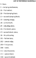
Fig. 1 is a perspective view of an embodiment of the present invention - a fixture for a key cutting machine; -
Fig. 2 is a cross-sectional view of an embodiment of the present invention - a fixture for a key cutting machine; -
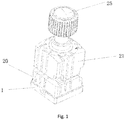
Fig. 3 is a schematic structural view of an embodiment of the first clamping block of the present invention; -
Fig. 4 is a schematic structural view of an embodiment of the second clamping block of the present invention; -
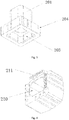
Fig. 5 is a schematic structural view of an embodiment of the base according to the present invention; -
Fig. 6 is a schematic structural view of an embodiment of the rotating wedge according to the present invention. - The embodiment, the function and the advantages of the object of the present invention will be further described with reference to the accompanying drawings.
- The technical solutions used in the embodiment of the present invention are clearly and completely described below with reference to the accompanying drawings. Obviously, the described embodiments are only a part of and not all of the embodiments of the present invention. All other embodiments obtained without creative efforts by technical personnel of ordinary skill in this technical field based on the embodiments of the present invention shall fall within the protection scope of the present invention.
- It should be noted that, all directional indicators (such as upper, lower, left, right, front, rear, ...) in the embodiments of the present invention are used for the sole purpose of explaining the relative spatial relations between the components and their movement in a specific position (as shown in the drawings), if the position changes, the said directional indicators will change accordingly.
- In addition, the descriptions such as "first", "second" and the like are used exclusively for the purpose of description and cannot be understood as indicating or suggesting relative importance or implying the number of the indicated technical features.
- Thus, features defined as "first" and "second" may explicitly or implicitly include at least one of the features. In addition, the technical solutions present in the various embodiments may be combined with each other, but they must be implementable by technical personnel skilled in this or the general technical field. When the combinations of the technical solutions appear contradictory or cannot be implemented, it should be considered that the combination of the technical solutions does not exist, nor is it within the protection scope of the present invention.
- It should be understood that the specific embodiments described herein are merely used to explain the present invention and are not intended to limit the present invention.
- With reference to
fig. 1-6 , a fixture for a key cutting machine according to the present invention includes abase 1, aclamping mechanism 2 and a rotating assembly, wherein thebase 1 holds and protects other parts of the said fixture for a key cutting machine. Theclamping mechanism 2 comprises afirst clamping block 20, asecond clamping block 21, acentral shaft 24 and an adjustingpiece 25. - One end of the
central shaft 24 is fixedly connected to thebase 1, the other end passes through thefirst clamping block 20 and thesecond clamping block 21 in sequence, from which it arrives at the adjustingpiece 25 and connects with the adjustingpiece 25. The key subject to cutting is placed between first clampingblock 20 and thesecond clamping block 21. The distance between thefirst clamping block 20 and thesecond clamping block 21 can be adjusted by the adjustingpiece 25 in order to clamp the key. The rotating assembly is disposed between thebase 1 and thefirst clamping block 20, so that thefirst clamping block 20 can form a rotating connection with thebase 1 through the rotating assembly. - The adjustment of the clamping can be realized by means of a threaded connection between the
central shaft 24 and the adjustingpiece 25. Thecentral shaft 24 is provided with a screw thread and the adjustingpiece 25 is provided with a screw thread adapted to the screw thread ofcentral shaft 24. Thecentral shaft 24 is connected with the adjustingpiece 25 through an internal screw thread. The adjustingpiece 25 can press or relax thesecond clamping block 21 by way of adjusting the length of the connection with the central shaft and thus control the clamping of the key. - For convenience of operation, an elastic piece may also be disposed between the
first clamping block 20 and thesecond clamping block 21 to create an interaction force between them. When the adjustingpiece 25 relaxes the force exerted on thesecond clamping block 21, thesecond clamping block 21 is automatically separated from thefirst clamping block 20 due to the elastic force. - In this embodiment, thanks to the rotation assembly, the rotation between the
first clamping block 20 and thebase 1 is created, that is to say, there is a transmission of motion between thefirst clamping block 20 and thebase 1 through the ratchet. Referring tofig. 5-6 , the rotating assembly includes arotating wedge 23 and thefirst ratchet 10 disposed on thebase 1. The rotatingwedge 23 is also equipped with thesecond ratchet 230 adapted to thefirst ratchet 10. The rotatingwedge 23 is arranged on thebase 1 through thesecond ratchet 230 and thefirst ratchet 10. When thefirst clamping block 20 is rotated, the rotatingwedge 23 is driven to rotate in a specific direction. Obviously, the rotating assembly is not limited to being provided as a ratchet mechanism, the rotation of thefirst clamping block 20 relative to thebase 1 can be achieved by means of another gear train mechanism. - Compared with the key cutting machine fixtures known to technicians skilled in this particular technical field, the present invention uses the rotating
assembly 23 as the rotating medium. Provided that the original size and volume of the fixture do not change, it can achieve more flexible, smoother and easier turning of theclamping mechanism 2 in relation to thebase 1, so as to complete the switching between the different clamping surfaces. What's more, it has a simple structure, takes little space and its production cost is low. It can better suit keys of various types and sizes found in key cutting engineering and improve the efficiency of key cutting. - Obviously, the key clamping position between the
first clamping block 20 and thesecond clamping block 21 constitutes a working space, one working space corresponds to one clamping surface. - Referring to
fig. 5-6 , in the present embodiment thefirst ratchet 10 is provided as a four-tooth ratchet, while thesecond ratchet 230 is provided as a four-tooth ratchet that matches thefirst ratchet 10, this means that the rotatingwedge 23 can be set at four different angles. In contrast, thefirst clamping block 20 and thesecond clamping block 21 are both arranged as rectangular prisms, whose side faces match one another to form four clamping spaces, i.e. there are four working spaces. Each working space corresponds to a different angle, when the rotatingwedge 23 turns by one tooth the working space turns accordingly by one. - In another embodiment, the
first ratchet 10 can be a six-teeth ratchet, while thesecond ratchet 230 can be arranged as a six-teeth ratchet that matches thefirst ratchet 10. In this way therotary wedge 23 can be turned to six different angles, which gives six clamping surfaces, each of which separately corresponds to each angle. - Of course, the present invention does not limit the number of teeth of the ratchet. According to actual needs, the
first ratchet 10 and thesecond ratchet 230 may be correspondingly arranged as multi-tooth ratchets. A plurality of working spaces can be set up, in accordance with the number of ratchet teeth, with each ratchet tooth corresponding to a separate working space. - Further, to ensure the right function of the fixture for key cutting machine, that is, to hold the key between the
first clamping block 20 and thesecond clamping block 21 and to be able to change the working space in a flexible manner, the aforementioned fixture for key cutting machine is arranged as follows:
Thesecond clamping block 21 is sleeved on thefirst clamping block 20 in a movable manner. Thesecond clamping block 21 can move along the axial direction relatively to thefirst clamping block 20; thesecond clamping block 21 and thefirst clamping block 20 are fixed in relation to each other in a tangential direction, that is to say there can be no relative rotation between the two blocks. The working space is formed between the top end of thesecond clamping block 21 moving towards thefirst clamping block 20 and the matching part of thefirst clamping block 20. - The
first clamping block 20 is sleeved on therotating wedge 23. Thefirst clamping block 20 and thesecond clamping block 21 can drive the rotatingwedge 23 to rotate simultaneously. Another option is that thefirst clamping block 20 drives both thesecond clamping block 21 and therotating wedge 23 to simultaneous rotation. The rotatingwedge 23 through the ratchets can control the movement of thefirst clamping block 20 and thesecond clamping block 21 to rotate in a fixed direction. Through the cooperation of therotating wedge 23 and thebase 1 the transition to different working spaces can be made. - In addition, in order to enable the
first clamping block 20 and thesecond clamping block 21 to drive the rotatingwedge 23 to rotation, as shown infig. 6 , the rotatingwedge 23 has a prism shape and is equipped with thesecond ratchet 230 that is directed towards the basal surface of thebase 1 and matches thefirst ratchet 10. Thefirst clamping block 20 possesses a prism-shapedhollow boss 201 extending in the direction opposite to the direction of movement of thesecond clamping block 21. On the opposite side of thehollow boss 201 there is thefirst groove 203 concaved inwardly. The first groove matches the external shape of therotary wedge 23. Therotary wedge 23 can be embedded in thefirst groove 203. Since therotary wedge 23 is prism-shaped, by turning thefirst clamping block 20 one can drive therotary wedge 23 to turn accordingly. - In addition, the
second clamping block 21 has thesecond groove 210 matched with thehollow boss 201. Thehollow boss 201 is inserted into thesecond groove 210 and can slide back and forth along the inside surface of thesecond groove 210. The gap between the side surface of thesecond groove 210 and the matching part of thefirst clamping block 20 is the working space. When a key is placed in the working space, thesecond clamping block 21 moves toward thefirst clamping block 20, which causes the side surface of thesecond groove 210 to press against and hold the key. - Obviously, in another embodiment, in order to enable the
first clamping block 20 and thesecond clamping block 21 to drive the rotatingwedge 23 to turn, the rotatingwedge 23 and thehollow boss 201 may also be shaped into a cylinder, on which a guiding slot needs to be arranged. Further, a guiding pin matching the guiding slot is arranged on the inner surface of thefirst groove 203 and thesecond groove 210, the guiding pin fits into the guiding groove, at the same time the guiding slot and the guiding pin fix the position of therotating wedge 23 and thefirst clamping block 20 so that both can rotate only relatively to the base at the same time and cannot rotate relatively to each other. In addition, since the guiding slot of thehollow boss 201 matches the guiding pin of thesecond groove 210, thesecond clamping block 21 can move in the axial direction relatively to thefirst clamping block 20 and thesecond clamping block 21, thefirst clamping block 20 and therotary wedge 23 can make a rotary movement being fixed in relation to each other at the same time. - In this embodiment, the elastic piece between the
first clamping block 20 and thesecond clamping block 21 is divided into two, that is, the firstelastic piece 26 and the secondelastic piece 27. Moreover, both of the elastic pieces are disposed in the inside part of thehollow boss 201 and sleeved on thecentral shaft 24. Thehollow boss 201 along its inner periphery has aconvex edge 202, the firstelastic piece 26 and the second elastic piece are separately disposed at the two sides of theconvex edge 202. - In the axial direction, one of the first
elastic piece 26 presses against the rotatingwedge 23 and the other abuts against theconvex edge 202 in this way providing a restoring force to the surface of the ratchet, allowing thesecond ratchet wheel 230 to automatically fix itself in thebase 1 when rotated to any of the fixed positions, one end of the secondelastic piece 27 abuts against thesecond clamping block 21 and the other presses against theconvex edge 202 providing a restoring force to thesecond clamping block 21, which enables thesecond clamping block 21 to press against the adjustingpiece 25 to make the two elements relatively static. Further, thesecond clamping block 21 due to the rotation of the adjusting piece moves relatively to thefirst clamping block 20, which enables the clamping and relaxing of the key. On the other hand, the second elastic piece may prevent thesecond clamping block 21 from moving thefirst clamping block 20 at the moment of releasing the key from thefirst clamping block 20. - The above-mentioned two elastic pieces of the key cutting machine fixture further improve the flexibility of switching between different clamping surfaces and help effectively overcome the defects and deficiencies of switching between different clamping surfaces in traditional key cutting machines fixtures such as jamming and inflexible switching.
- Specifically, the elastic piece in the present embodiment is provided as a spring.
- In addition, the adjusting
piece 25 is also equipped with athrust bearing 28, thethrust bearing 28 is sleeved on the outer periphery of thecentral shaft 24 and pressed against thesecond clamping block 21, so as to prevent the adjustingpiece 25 from directly touching the end surface of thesecond clamping block 21, avoiding the abrasion caused by frequent rotation, at the same time reducing the resistance of the adjustingpiece 25, which improves the efficiency of adjusting. - In order to make the relative rotation between the
base 1 and therotating wedge 23 more effective, thebase 1 and therotating wedge 23 are provided with outwardly protruding circular bosses, thefirst ratchet 10 is disposed on the end surface of the circular boss of thebase 1, thesecond ratchet 230 is disposed on the end surface of the circular boss of therotating wedge 23. - The above-mentioned key cutting machine fixture is further provided with a fool-proof mechanism for pairing the
first clamping block 20 and thesecond clamping block 21 so as to avoid errors in the assembly process. In this embodiment the foolproof mechanism includes aconvex block 211 protruding outwardly from the side edge of thesecond groove 210 of thesecond clamping block 21 and anotch 204 that is arranged on thefirst clamping block 20 and matches theconvex block 211. If the mechanism is correctly installed, theconvex block 211 can be embedded in thenotch 204. If it is installed incorrectly, theconvex block 211 abuts against thefirst clamping block 20 and the key cannot be clamped. - In addition, the fool-proof mechanism is not limited to the above arrangement, it can be also implemented through different configurations of the
first clamping block 20 and thesecond clamping block 21, so that thefirst clamping block 20 and thesecond clamping block 21 match one another. - The present invention further provides a key cutting machine that includes the above-mentioned fixture for a key cutting machine, and in particular, a machine that possess two of the above-mentioned fixtures for a key cutting machine for holding the key blank and the copy key respectively.
- The above is only a preferred embodiment of the present invention and does not intend to limit the scope of the present invention. Any use of equivalent structure or equivalent process alteration made according to the content of these instructions and drawings or any direct or indirect application thereof in other related technical field are equally included in the protection scope of the present invention.
Claims (9)
- A fixture for a key cutting machine, comprising: a base 1, a clamping mechanism 2 and a rotating assembly, wherein the clamping mechanism 2 comprises a first clamping block 20, a second clamping block 21, a central shaft 24 and an adjusting piece 25, wherein one end of the central shaft 24 is connected to the base 1 and sequentially passes through the first clamping block 20 and the second clamping block 21, wherein the adjusting piece 25 is disposed at the other end of the central shaft 24 for adjusting the distance between the first clamping block 20 and the second clamping block 21 in order to hold the key, wherein the rotating assembly is disposed between the first clamping block 20 and the base 1, the first clamping block 20 is rotationally connected to the base 1.
- The fixture for a key cutting machine according to claim 1, wherein the rotating assembly comprises a rotating wedge 23 and a first ratchet 10 which is arranged on the base 1, wherein the rotating wedge 23 disposed on the base 1 possesses a second ratchet 230 matched with the first ratchet 10, wherein the rotating wedge 23 is rotationally connected with the base 1 through the first ratchet 10 and the second ratchet 230.
- The fixture for a key cutting machine according to claim 2, wherein a working space for holding a key is formed between the first clamping block 20 and the second clamping block 21, wherein the number of the ratchet teeth is the same as the number of such working spaces, wherein the second ratchet 230 being set up to be matched with the first ratchet 10 and each ratchet corresponding to one working space.
- The fixture for a key cutting machine according to claim 3, wherein the second clamping block 21 is sleeved on the first clamping block 20 so that the second clamping block 21 can only make an axial movement relative to the first clamping block 20, wherein the first clamping block 20 is sleeved on the rotating wedge 23 so that the first clamping block 20 and the rotating wedge 23 are fixed in relation to each other, wherein the working space is formed between the head of the second clamping block 21 moving towards the first clamping block 20 and the corresponding position of the first clamping block 20.
- The fixture for a key cutting machine according to claim 4, wherein the first clamping block 20 has a hollow boss 201, and the second clamping block 21 is sleeved on the said hollow boss 201, wherein inside the said hollow boss a convex edge 202 is arranged along the inner periphery, wherein two sides of the convex edge 202 are respectively provided with a first elastic piece 26 and a second elastic piece 27, wherein one end of the first elastic piece 26 abuts against the above-mentioned rotating wedge 23 and the other end abuts against the said convex edge 202, wherein one end of the second elastic piece 27 abuts against the second clamping block 21 and the other end presses against the convex edge 202.
- The fixture for a key cutting machine according to claim 1, wherein the fixture comprises a thrust bearing 28 provided in the adjusting piece 25 and sleeved around the outer circumference of the center shaft 24, wherein the thrust bearing 28 presses against the second clamping block 21.
- The fixture for a key cutting machine according to claim 2, wherein both the base 1 and the rotating wedge 23 are provided with a circular boss protruding outwardly, wherein the first ratchet 10 is arranged on the end plane of the circular boss of the base, wherein the second ratchet 230 being provided on the end plane of the circular boss of the rotating wedge 23.
- The fixture for a key cutting machine according to claim 4, wherein the fixture comprises a fool-proof mechanism for pairing the first clamping block 20 and the second clamping block 21, wherein the fool-proof mechanism includes a protrusion provided on the top end of the second clamping block 21 moving towards the first clamping block 20 and a notch 204 provided on the first clamping block 20 adapted to the protrusion.
- A key cutting machine according to claim 1, wherein the key cutting machine comprises the fixture for a key cutting machine.
Applications Claiming Priority (1)
| Application Number | Priority Date | Filing Date | Title |
|---|---|---|---|
| CN201710566435.6A CN107186512B (en) | 2017-07-12 | 2017-07-12 | Key processing machine and fixture for key processing machine |
Publications (2)
| Publication Number | Publication Date |
|---|---|
| EP3427879A1 true EP3427879A1 (en) | 2019-01-16 |
| EP3427879B1 EP3427879B1 (en) | 2021-07-07 |
Family
ID=59882363
Family Applications (1)
| Application Number | Title | Priority Date | Filing Date |
|---|---|---|---|
| EP18161855.4A Active EP3427879B1 (en) | 2017-07-12 | 2018-03-14 | Fixture for key cutting machine and key cutting machine |
Country Status (4)
| Country | Link |
|---|---|
| US (1) | US10688568B2 (en) |
| EP (1) | EP3427879B1 (en) |
| CN (1) | CN107186512B (en) |
| ES (1) | ES2890856T3 (en) |
Cited By (1)
| Publication number | Priority date | Publication date | Assignee | Title |
|---|---|---|---|---|
| EP3698908A3 (en) * | 2019-01-29 | 2020-12-09 | Shenzhen Xhorse Electronics Co., Ltd | Key duplicating machines clamp bench and key duplicating machine |
Families Citing this family (4)
| Publication number | Priority date | Publication date | Assignee | Title |
|---|---|---|---|---|
| CN107186512B (en) * | 2017-07-12 | 2023-09-12 | 深圳数马电子技术有限公司 | Key processing machine and fixture for key processing machine |
| CN110125704A (en) * | 2019-06-05 | 2019-08-16 | 湖南森普罗科技有限公司 | A kind of Key clamping-unit |
| CN112192274B (en) * | 2020-10-10 | 2022-04-19 | 深圳数马电子技术有限公司 | Key blank positioning method and device applied to key processing machine |
| GB202017736D0 (en) * | 2020-11-10 | 2020-12-23 | Iconx Ltd | Key clamp |
Citations (4)
| Publication number | Priority date | Publication date | Assignee | Title |
|---|---|---|---|---|
| IT1195639B (en) * | 1983-12-16 | 1988-10-19 | Silca Spa | CLAMP FOR KEY AND SIMILAR DUPLICATING MACHINES |
| JP2000354907A (en) * | 1999-06-11 | 2000-12-26 | Clover:Kk | Cutting machine of duplicate key |
| WO2008065052A1 (en) * | 2006-11-30 | 2008-06-05 | Silca S.P.A. | Clamp for a key cutting machine. |
| WO2015011095A1 (en) * | 2013-07-24 | 2015-01-29 | Silca S.P.A. | Clamp for a key duplicating machine |
Family Cites Families (13)
| Publication number | Priority date | Publication date | Assignee | Title |
|---|---|---|---|---|
| US4084369A (en) * | 1977-05-02 | 1978-04-18 | Luebbers Herman E | Chain link assembly and disassembly tool |
| GB2392711B (en) * | 2002-09-03 | 2004-08-18 | Auto Service Tools Ltd | Holding device |
| US7780668B2 (en) * | 2007-03-02 | 2010-08-24 | Musculoskeletal Transplant Foundation | Osteochondral allograft cartilage transplant workstation |
| US20090283951A1 (en) * | 2008-05-13 | 2009-11-19 | Patrick Rowley | Clamp assembly |
| US9233444B2 (en) * | 2014-02-27 | 2016-01-12 | Toyota Motor Engineering & Manufacturing North America, Inc. | Adjustable key block assemblies and associated methods of adjusting extra large workpieces |
| US10179392B2 (en) * | 2015-01-23 | 2019-01-15 | Chris Taylor | Multi_station fixture vise |
| CN204704255U (en) * | 2015-01-26 | 2015-10-14 | 杭州安费诺飞凤通信部品有限公司 | The unidirectional friction shaft hinge of easy switch and mobile electronic product terminal |
| CN205271599U (en) * | 2015-12-30 | 2016-06-01 | 深圳数马电子技术有限公司 | Key is anchor clamps for doubling machine |
| CN205290415U (en) * | 2016-01-20 | 2016-06-08 | 深圳市创顶峰科技有限公司 | Position anchor clamps subassemblies that press from both sides more with adjustable |
| CN205520509U (en) * | 2016-03-11 | 2016-08-31 | 张远文 | Key doubling machine anchor clamps mounting structure |
| CN106088893B (en) * | 2016-07-28 | 2017-11-28 | 谭芳 | Concealed door closer |
| CN206883240U (en) * | 2017-07-12 | 2018-01-16 | 深圳数马电子技术有限公司 | Saltation layer machine and saltation layer machine fixture |
| CN107186512B (en) * | 2017-07-12 | 2023-09-12 | 深圳数马电子技术有限公司 | Key processing machine and fixture for key processing machine |
-
2017
- 2017-07-12 CN CN201710566435.6A patent/CN107186512B/en active Active
-
2018
- 2018-03-14 EP EP18161855.4A patent/EP3427879B1/en active Active
- 2018-03-14 ES ES18161855T patent/ES2890856T3/en active Active
- 2018-03-14 US US15/921,638 patent/US10688568B2/en active Active
Patent Citations (4)
| Publication number | Priority date | Publication date | Assignee | Title |
|---|---|---|---|---|
| IT1195639B (en) * | 1983-12-16 | 1988-10-19 | Silca Spa | CLAMP FOR KEY AND SIMILAR DUPLICATING MACHINES |
| JP2000354907A (en) * | 1999-06-11 | 2000-12-26 | Clover:Kk | Cutting machine of duplicate key |
| WO2008065052A1 (en) * | 2006-11-30 | 2008-06-05 | Silca S.P.A. | Clamp for a key cutting machine. |
| WO2015011095A1 (en) * | 2013-07-24 | 2015-01-29 | Silca S.P.A. | Clamp for a key duplicating machine |
Cited By (1)
| Publication number | Priority date | Publication date | Assignee | Title |
|---|---|---|---|---|
| EP3698908A3 (en) * | 2019-01-29 | 2020-12-09 | Shenzhen Xhorse Electronics Co., Ltd | Key duplicating machines clamp bench and key duplicating machine |
Also Published As
| Publication number | Publication date |
|---|---|
| EP3427879B1 (en) | 2021-07-07 |
| CN107186512A (en) | 2017-09-22 |
| ES2890856T3 (en) | 2022-01-24 |
| US20190015908A1 (en) | 2019-01-17 |
| US10688568B2 (en) | 2020-06-23 |
| CN107186512B (en) | 2023-09-12 |
Similar Documents
| Publication | Publication Date | Title |
|---|---|---|
| US10688568B2 (en) | Key cutting machine and a fixture for key cutting machine | |
| US11154974B2 (en) | Hand-held tool and clamping device thereof | |
| CN201720719U (en) | Universal fixture for milled root, assembling surface and molded surface of one-million KW turbine blade | |
| AU2013404787B2 (en) | Miter saw | |
| TWI530355B (en) | Tool changing device | |
| US20190151959A1 (en) | Hole saw and component thereof | |
| US20140150579A1 (en) | Axial adjustment device | |
| TWI592261B (en) | Tool post with high structural strength | |
| KR20130017499A (en) | Milling machine vise that is capable of controlling angle | |
| US10525571B2 (en) | Screwdriver and ratchet mechanism thereof | |
| US8776655B2 (en) | Worktable for circular saws | |
| US8910534B2 (en) | Rotation adjusting mechanism and adjusting machine using the same | |
| US2368843A (en) | Clamp | |
| JP2013521139A5 (en) | ||
| JP4892510B2 (en) | Cutting machine | |
| KR20120119506A (en) | A nc rotary table apparatus | |
| CN206883240U (en) | Saltation layer machine and saltation layer machine fixture | |
| US20140202270A1 (en) | Worktable sliding block positioning mechanism | |
| GB2587714A (en) | Power tool structure | |
| CN110900275A (en) | Improved structure of disc type tool magazine | |
| WO2019047951A1 (en) | Electric saw | |
| RU128137U1 (en) | COMBINED TURNING CUTTER | |
| CN103537758B (en) | Power tool | |
| CN205765850U (en) | A kind of detent mechanism positioning multiple instrument | |
| CN210412689U (en) | Lithium electric drill |
Legal Events
| Date | Code | Title | Description |
|---|---|---|---|
| PUAI | Public reference made under article 153(3) epc to a published international application that has entered the european phase |
Free format text: ORIGINAL CODE: 0009012 |
|
| STAA | Information on the status of an ep patent application or granted ep patent |
Free format text: STATUS: THE APPLICATION HAS BEEN PUBLISHED |
|
| AK | Designated contracting states |
Kind code of ref document: A1 Designated state(s): AL AT BE BG CH CY CZ DE DK EE ES FI FR GB GR HR HU IE IS IT LI LT LU LV MC MK MT NL NO PL PT RO RS SE SI SK SM TR |
|
| AX | Request for extension of the european patent |
Extension state: BA ME |
|
| STAA | Information on the status of an ep patent application or granted ep patent |
Free format text: STATUS: REQUEST FOR EXAMINATION WAS MADE |
|
| 17P | Request for examination filed |
Effective date: 20190710 |
|
| RBV | Designated contracting states (corrected) |
Designated state(s): AL AT BE BG CH CY CZ DE DK EE ES FI FR GB GR HR HU IE IS IT LI LT LU LV MC MK MT NL NO PL PT RO RS SE SI SK SM TR |
|
| GRAP | Despatch of communication of intention to grant a patent |
Free format text: ORIGINAL CODE: EPIDOSNIGR1 |
|
| STAA | Information on the status of an ep patent application or granted ep patent |
Free format text: STATUS: GRANT OF PATENT IS INTENDED |
|
| INTG | Intention to grant announced |
Effective date: 20210118 |
|
| RAP1 | Party data changed (applicant data changed or rights of an application transferred) |
Owner name: SHENZHEN XHORSE ELECTRONICS CO., LTD |
|
| RIN1 | Information on inventor provided before grant (corrected) |
Inventor name: XI, YONGFENG Inventor name: CHEN, JUNFENG Inventor name: HAO, YIJIE Inventor name: CAO, GUOZHONG Inventor name: LI, CHENGLONG Inventor name: HAN, SHITTING Inventor name: HE, YUAN |
|
| GRAS | Grant fee paid |
Free format text: ORIGINAL CODE: EPIDOSNIGR3 |
|
| GRAA | (expected) grant |
Free format text: ORIGINAL CODE: 0009210 |
|
| STAA | Information on the status of an ep patent application or granted ep patent |
Free format text: STATUS: THE PATENT HAS BEEN GRANTED |
|
| AK | Designated contracting states |
Kind code of ref document: B1 Designated state(s): AL AT BE BG CH CY CZ DE DK EE ES FI FR GB GR HR HU IE IS IT LI LT LU LV MC MK MT NL NO PL PT RO RS SE SI SK SM TR |
|
| REG | Reference to a national code |
Ref country code: GB Ref legal event code: FG4D |
|
| REG | Reference to a national code |
Ref country code: AT Ref legal event code: REF Ref document number: 1408075 Country of ref document: AT Kind code of ref document: T Effective date: 20210715 |
|
| REG | Reference to a national code |
Ref country code: DE Ref legal event code: R096 Ref document number: 602018019549 Country of ref document: DE |
|
| REG | Reference to a national code |
Ref country code: IE Ref legal event code: FG4D |
|
| REG | Reference to a national code |
Ref country code: LT Ref legal event code: MG9D |
|
| REG | Reference to a national code |
Ref country code: NL Ref legal event code: MP Effective date: 20210707 |
|
| REG | Reference to a national code |
Ref country code: AT Ref legal event code: MK05 Ref document number: 1408075 Country of ref document: AT Kind code of ref document: T Effective date: 20210707 |
|
| REG | Reference to a national code |
Ref country code: ES Ref legal event code: FG2A Ref document number: 2890856 Country of ref document: ES Kind code of ref document: T3 Effective date: 20220124 |
|
| PG25 | Lapsed in a contracting state [announced via postgrant information from national office to epo] |
Ref country code: SE Free format text: LAPSE BECAUSE OF FAILURE TO SUBMIT A TRANSLATION OF THE DESCRIPTION OR TO PAY THE FEE WITHIN THE PRESCRIBED TIME-LIMIT Effective date: 20210707 Ref country code: RS Free format text: LAPSE BECAUSE OF FAILURE TO SUBMIT A TRANSLATION OF THE DESCRIPTION OR TO PAY THE FEE WITHIN THE PRESCRIBED TIME-LIMIT Effective date: 20210707 Ref country code: FI Free format text: LAPSE BECAUSE OF FAILURE TO SUBMIT A TRANSLATION OF THE DESCRIPTION OR TO PAY THE FEE WITHIN THE PRESCRIBED TIME-LIMIT Effective date: 20210707 Ref country code: HR Free format text: LAPSE BECAUSE OF FAILURE TO SUBMIT A TRANSLATION OF THE DESCRIPTION OR TO PAY THE FEE WITHIN THE PRESCRIBED TIME-LIMIT Effective date: 20210707 Ref country code: NO Free format text: LAPSE BECAUSE OF FAILURE TO SUBMIT A TRANSLATION OF THE DESCRIPTION OR TO PAY THE FEE WITHIN THE PRESCRIBED TIME-LIMIT Effective date: 20211007 Ref country code: NL Free format text: LAPSE BECAUSE OF FAILURE TO SUBMIT A TRANSLATION OF THE DESCRIPTION OR TO PAY THE FEE WITHIN THE PRESCRIBED TIME-LIMIT Effective date: 20210707 Ref country code: PT Free format text: LAPSE BECAUSE OF FAILURE TO SUBMIT A TRANSLATION OF THE DESCRIPTION OR TO PAY THE FEE WITHIN THE PRESCRIBED TIME-LIMIT Effective date: 20211108 Ref country code: AT Free format text: LAPSE BECAUSE OF FAILURE TO SUBMIT A TRANSLATION OF THE DESCRIPTION OR TO PAY THE FEE WITHIN THE PRESCRIBED TIME-LIMIT Effective date: 20210707 Ref country code: BG Free format text: LAPSE BECAUSE OF FAILURE TO SUBMIT A TRANSLATION OF THE DESCRIPTION OR TO PAY THE FEE WITHIN THE PRESCRIBED TIME-LIMIT Effective date: 20211007 Ref country code: LT Free format text: LAPSE BECAUSE OF FAILURE TO SUBMIT A TRANSLATION OF THE DESCRIPTION OR TO PAY THE FEE WITHIN THE PRESCRIBED TIME-LIMIT Effective date: 20210707 |
|
| PG25 | Lapsed in a contracting state [announced via postgrant information from national office to epo] |
Ref country code: PL Free format text: LAPSE BECAUSE OF FAILURE TO SUBMIT A TRANSLATION OF THE DESCRIPTION OR TO PAY THE FEE WITHIN THE PRESCRIBED TIME-LIMIT Effective date: 20210707 Ref country code: LV Free format text: LAPSE BECAUSE OF FAILURE TO SUBMIT A TRANSLATION OF THE DESCRIPTION OR TO PAY THE FEE WITHIN THE PRESCRIBED TIME-LIMIT Effective date: 20210707 Ref country code: GR Free format text: LAPSE BECAUSE OF FAILURE TO SUBMIT A TRANSLATION OF THE DESCRIPTION OR TO PAY THE FEE WITHIN THE PRESCRIBED TIME-LIMIT Effective date: 20211008 |
|
| REG | Reference to a national code |
Ref country code: DE Ref legal event code: R097 Ref document number: 602018019549 Country of ref document: DE |
|
| PG25 | Lapsed in a contracting state [announced via postgrant information from national office to epo] |
Ref country code: DK Free format text: LAPSE BECAUSE OF FAILURE TO SUBMIT A TRANSLATION OF THE DESCRIPTION OR TO PAY THE FEE WITHIN THE PRESCRIBED TIME-LIMIT Effective date: 20210707 |
|
| PLBE | No opposition filed within time limit |
Free format text: ORIGINAL CODE: 0009261 |
|
| STAA | Information on the status of an ep patent application or granted ep patent |
Free format text: STATUS: NO OPPOSITION FILED WITHIN TIME LIMIT |
|
| PG25 | Lapsed in a contracting state [announced via postgrant information from national office to epo] |
Ref country code: SM Free format text: LAPSE BECAUSE OF FAILURE TO SUBMIT A TRANSLATION OF THE DESCRIPTION OR TO PAY THE FEE WITHIN THE PRESCRIBED TIME-LIMIT Effective date: 20210707 Ref country code: SK Free format text: LAPSE BECAUSE OF FAILURE TO SUBMIT A TRANSLATION OF THE DESCRIPTION OR TO PAY THE FEE WITHIN THE PRESCRIBED TIME-LIMIT Effective date: 20210707 Ref country code: RO Free format text: LAPSE BECAUSE OF FAILURE TO SUBMIT A TRANSLATION OF THE DESCRIPTION OR TO PAY THE FEE WITHIN THE PRESCRIBED TIME-LIMIT Effective date: 20210707 Ref country code: EE Free format text: LAPSE BECAUSE OF FAILURE TO SUBMIT A TRANSLATION OF THE DESCRIPTION OR TO PAY THE FEE WITHIN THE PRESCRIBED TIME-LIMIT Effective date: 20210707 Ref country code: CZ Free format text: LAPSE BECAUSE OF FAILURE TO SUBMIT A TRANSLATION OF THE DESCRIPTION OR TO PAY THE FEE WITHIN THE PRESCRIBED TIME-LIMIT Effective date: 20210707 Ref country code: AL Free format text: LAPSE BECAUSE OF FAILURE TO SUBMIT A TRANSLATION OF THE DESCRIPTION OR TO PAY THE FEE WITHIN THE PRESCRIBED TIME-LIMIT Effective date: 20210707 |
|
| 26N | No opposition filed |
Effective date: 20220408 |
|
| PGFP | Annual fee paid to national office [announced via postgrant information from national office to epo] |
Ref country code: TR Payment date: 20220908 Year of fee payment: 5 |
|
| PGFP | Annual fee paid to national office [announced via postgrant information from national office to epo] |
Ref country code: CH Payment date: 20220905 Year of fee payment: 5 |
|
| PGFP | Annual fee paid to national office [announced via postgrant information from national office to epo] |
Ref country code: MC Payment date: 20230622 Year of fee payment: 6 Ref country code: IT Payment date: 20230621 Year of fee payment: 6 Ref country code: DE Payment date: 20230621 Year of fee payment: 6 |
|
| PGFP | Annual fee paid to national office [announced via postgrant information from national office to epo] |
Ref country code: LU Payment date: 20230621 Year of fee payment: 6 |
|
| PGFP | Annual fee paid to national office [announced via postgrant information from national office to epo] |
Ref country code: BE Payment date: 20230621 Year of fee payment: 6 |
|
| PGFP | Annual fee paid to national office [announced via postgrant information from national office to epo] |
Ref country code: GB Payment date: 20230620 Year of fee payment: 6 |
|
| REG | Reference to a national code |
Ref country code: CH Ref legal event code: PL |
|
| PGFP | Annual fee paid to national office [announced via postgrant information from national office to epo] |
Ref country code: ES Payment date: 20231002 Year of fee payment: 6 |
|
| PG25 | Lapsed in a contracting state [announced via postgrant information from national office to epo] |
Ref country code: LI Free format text: LAPSE BECAUSE OF NON-PAYMENT OF DUE FEES Effective date: 20230331 Ref country code: CH Free format text: LAPSE BECAUSE OF NON-PAYMENT OF DUE FEES Effective date: 20230331 |
|
| PGFP | Annual fee paid to national office [announced via postgrant information from national office to epo] |
Ref country code: IE Payment date: 20231002 Year of fee payment: 6 Ref country code: FR Payment date: 20231002 Year of fee payment: 6 |
|
| PG25 | Lapsed in a contracting state [announced via postgrant information from national office to epo] |
Ref country code: HU Free format text: LAPSE BECAUSE OF FAILURE TO SUBMIT A TRANSLATION OF THE DESCRIPTION OR TO PAY THE FEE WITHIN THE PRESCRIBED TIME-LIMIT; INVALID AB INITIO Effective date: 20180314 |
|
| PG25 | Lapsed in a contracting state [announced via postgrant information from national office to epo] |
Ref country code: MK Free format text: LAPSE BECAUSE OF FAILURE TO SUBMIT A TRANSLATION OF THE DESCRIPTION OR TO PAY THE FEE WITHIN THE PRESCRIBED TIME-LIMIT Effective date: 20210707 Ref country code: CY Free format text: LAPSE BECAUSE OF FAILURE TO SUBMIT A TRANSLATION OF THE DESCRIPTION OR TO PAY THE FEE WITHIN THE PRESCRIBED TIME-LIMIT Effective date: 20210707 |