EP3427841A1 - Maskierungsverfahren - Google Patents
Maskierungsverfahren Download PDFInfo
- Publication number
- EP3427841A1 EP3427841A1 EP17382361.8A EP17382361A EP3427841A1 EP 3427841 A1 EP3427841 A1 EP 3427841A1 EP 17382361 A EP17382361 A EP 17382361A EP 3427841 A1 EP3427841 A1 EP 3427841A1
- Authority
- EP
- European Patent Office
- Prior art keywords
- section
- frisket
- jamming element
- aeronautical structure
- elevator
- Prior art date
- Legal status (The legal status is an assumption and is not a legal conclusion. Google has not performed a legal analysis and makes no representation as to the accuracy of the status listed.)
- Withdrawn
Links
Images




Classifications
-
- B—PERFORMING OPERATIONS; TRANSPORTING
- B64—AIRCRAFT; AVIATION; COSMONAUTICS
- B64F—GROUND OR AIRCRAFT-CARRIER-DECK INSTALLATIONS SPECIALLY ADAPTED FOR USE IN CONNECTION WITH AIRCRAFT; DESIGNING, MANUFACTURING, ASSEMBLING, CLEANING, MAINTAINING OR REPAIRING AIRCRAFT, NOT OTHERWISE PROVIDED FOR; HANDLING, TRANSPORTING, TESTING OR INSPECTING AIRCRAFT COMPONENTS, NOT OTHERWISE PROVIDED FOR
- B64F5/00—Designing, manufacturing, assembling, cleaning, maintaining or repairing aircraft, not otherwise provided for; Handling, transporting, testing or inspecting aircraft components, not otherwise provided for
-
- B—PERFORMING OPERATIONS; TRANSPORTING
- B05—SPRAYING OR ATOMISING IN GENERAL; APPLYING FLUENT MATERIALS TO SURFACES, IN GENERAL
- B05B—SPRAYING APPARATUS; ATOMISING APPARATUS; NOZZLES
- B05B12/00—Arrangements for controlling delivery; Arrangements for controlling the spray area
- B05B12/16—Arrangements for controlling delivery; Arrangements for controlling the spray area for controlling the spray area
- B05B12/20—Masking elements, i.e. elements defining uncoated areas on an object to be coated
- B05B12/24—Masking elements, i.e. elements defining uncoated areas on an object to be coated made at least partly of flexible material, e.g. sheets of paper or fabric
-
- B—PERFORMING OPERATIONS; TRANSPORTING
- B25—HAND TOOLS; PORTABLE POWER-DRIVEN TOOLS; MANIPULATORS
- B25J—MANIPULATORS; CHAMBERS PROVIDED WITH MANIPULATION DEVICES
- B25J11/00—Manipulators not otherwise provided for
-
- B—PERFORMING OPERATIONS; TRANSPORTING
- B05—SPRAYING OR ATOMISING IN GENERAL; APPLYING FLUENT MATERIALS TO SURFACES, IN GENERAL
- B05B—SPRAYING APPARATUS; ATOMISING APPARATUS; NOZZLES
- B05B12/00—Arrangements for controlling delivery; Arrangements for controlling the spray area
- B05B12/16—Arrangements for controlling delivery; Arrangements for controlling the spray area for controlling the spray area
- B05B12/20—Masking elements, i.e. elements defining uncoated areas on an object to be coated
- B05B12/26—Masking elements, i.e. elements defining uncoated areas on an object to be coated for masking cavities
-
- B—PERFORMING OPERATIONS; TRANSPORTING
- B05—SPRAYING OR ATOMISING IN GENERAL; APPLYING FLUENT MATERIALS TO SURFACES, IN GENERAL
- B05B—SPRAYING APPARATUS; ATOMISING APPARATUS; NOZZLES
- B05B13/00—Machines or plants for applying liquids or other fluent materials to surfaces of objects or other work by spraying, not covered by groups B05B1/00 - B05B11/00
- B05B13/005—Machines or plants for applying liquids or other fluent materials to surfaces of objects or other work by spraying, not covered by groups B05B1/00 - B05B11/00 mounted on vehicles or designed to apply a liquid on a very large surface, e.g. on the road, on the surface of large containers
Definitions
- the present invention belongs to the field of painting, in particular to the field of masking large structures, difficult to handle, in order to avoid painting over non-intended areas. More specifically, the invention is of special application in any time-demanding industry as aeronautics, such as for painting a lifting surface like a wing or HTP.
- Painting is a usual labour to carry out in aircrafts both during its manufacturing and during later maintenance.
- the common purposes for painting an aircraft comprise enhancing the protection from the operational environment, deterioration and corrosion, and likewise for identification as belonging to a company or organization, aesthetically.
- a properly painted aircraft is easier to clean and maintain because the exposed surfaces are more resistant to corrosion and dirt, while oil does not adhere as readily to the surface.
- the overall process of painting is a sequence of steps which comprises, among others, washing the structure and moving into a stable clean environment, preparing the surface as necessary, masking the elements non-intended for painting, positioning the paint scheme, and finally painting and evaluating the result.
- painting stage tends to be a bottleneck for large structures, while many operations, identified with lead times, should be done prior to paint.
- the highest lead time in large aeronautical structures such as a lifting surface corresponds to the process of masking the areas non-intended to be painted, such as erosion plates and control surfaces, e.g. elevator, rudder...
- This process of masking is known as the use of materials for protecting areas from change like being unintendedly painted, or to focus change on other areas.
- the masking process is decisive in the field of painting in aeronautical industry, especially when manufacturing the lifting surface like the Horizontal Tail Plane (HTP).
- HTP Horizontal Tail Plane
- the present invention provides a solution for the aforementioned problems, by a method for masking an aeronautical structure according to claim 1, a method for painting an aeronautical structure according to claim 14, a jamming element according to claim 15, and an aeronautical structure according to claim 16.
- a method for masking an aeronautical structure according to claim 1 a method for painting an aeronautical structure according to claim 14, a jamming element according to claim 15, and an aeronautical structure according to claim 16.
- preferred embodiments of the invention are defined.
- the invention provides a method for masking an aeronautical structure with a frisket before painting such aeronautical structure, the aeronautical structure comprising a first section and a second section separated by a border, the method comprising the steps of:
- frisket is a single sheet that covers the entire working area.
- the at least one hole in the first and/or the second section means that such at least one hole may be arranged entirely on the surface of either the first section or second section; or may be arranged over the border between said first and second sections.
- this method allows, among others:
- any jamming element to be used has a corresponding hole, in the first and/or the second section, with a slightly smaller cross-sectional shape so that the jamming element is stuck along the periphery of said hole when inserted.
- inserting the at least one jamming element into the at least one hole of the first and/or second section means that the jamming element may be allocated up to the ground level of the first and/or second section; however, the inserting stops at the level in which it is stuck along the periphery of the hole.
- the frisket comprises more than one portions adapted to be joined between them, wherein the joined portions of the frisket comprises an area substantially similar to the first section intended to be masked.
- the at least one jamming element provided in step c) comprises:
- the step g) comprises covering the at least one jamming element with the frisket.
- the frisket is firstly arranged partially over the at least one hole towards the second section of the aeronautical structure; and after inserting the at least one jamming element into said at least one hole, the frisket is flipped over the jamming element in the opposite direction, towards the first section, for wrapping said first section.
- the at least one jamming element remains covered by the frisket preventing also from being painted.
- this allows a better placement of the frisket wrapping the first section of the aeronautical structure and this also assures that the frisket may be reused several times.
- the sealing strip will be understood as a long, dimensionally constant and narrow piece of an elastic material able to be housed into the slot of the jamming element, helping to prevent leakage of paint or another surface treatment, or exclude contamination, where the two sections join, i.e. the border.
- the sealing strip prevents leakage from the second section towards the first section, during painting or applying a surface treatment on the second section. Once positioned, the sealing strip remains in contact throughout all its length with the border between the first and second sections.
- the method further comprises inserting a pin along with a portion of the frisket into a recess of the external surface of the at least one jamming element, attaching the frisket thereby.
- the pin is thereby stuck into the recess along with a portion of the frisket, or may be otherwise piercing said portion of frisket to attach it.
- this allows that the frisket wraps closer the first section of the aeronautical structure, therefore preventing better its painting or application of the surface treatment.
- the steps e) to h) are performed automatically by at least one tool-head robot that comprises at least one robotic arm and at least one six-axis head.
- the robot may be a machine or part of a machine in which a tool or tool holder of is mounted and which is provided with adjustments to bring the tool into the desired position to perform automatically the programmed tasks.
- the at least one six-axis head mounted on the robotic arm it is possible to move the tools into the three dimensions (XYZ) and also to rotate over the three main rotational axes (Pitch, Roll, Yaw).
- This six-axis head is configured to mount any tooling required to carry out the tasks during the masking.
- the inventive solution about using a simpler and easier method to perform the method, in combination with using a programmed tool-head robot to perform the arranging and wrapping the frisket, and the inserting and placing of the jamming element and the C-shaped jamming elements (also the sealing strip if applies), give rise to a more effective process, reducing the lead time of the masking task thereby.
- the at least one jamming element provided in step c) further comprises QR codes or radio frequency identifications configured to be identified by the tool-head robot.
- each jamming element is configured to be inserted into a corresponding hole, if a wrong jamming element is brought by the tool-head robot and inserted into a non-corresponding hole, such jamming element may fall into such hole or being too big as to enter in such hole. Likewise, the same drawback is arisen about the C-shaped jamming element.
- the frisket provided in step b) is made of a membrane or a fiber reinforced polymer.
- the robotic arm needs means for bringing the frisket, e.g. by clams or suckers, the frisket need to be more resistant than current friskets, which are weak and breakable, being substituted thus by a thicker one.
- the at least one jamming element and the at least one C-shaped jamming element provided in steps c) and d), are manufactured by an additive manufacturing machine, such as a 3D printing machine.
- additive manufacturing technology such as 3D printing, eases the "in-situ” testing of the method and the initial set-up in different aeronautical structures. Furthermore, it allows manufacturing fast and economically the jamming elements and the C-shaped jamming elements providing higher versatility on painting stage; along with retrofitability to be used between different aeronautical structures. Later on, definitive devices for the method can be manufactured in other more appropriate materials/technologies.
- the aeronautical structure provided in step a) is a lifting surface, preferably a Horizontal Tail Plane (HTP), wherein the second section is a torsion box, and the first section is an elevator of the lifting surface.
- HTP Horizontal Tail Plane
- the lifting surface such as an HTP
- HTP high-power plasma lifting surface
- the at least one hole of the aeronautical structure provided in step a) is an elevator bearing rib hole located adjacent to the border.
- the elevator bearing rib holes are housings located in the upper surface of the Horizontal Tail Plane, those housings are intended for inspection of the ribs of the aeronautical structure from outside. Therefore, those housings are elements present in the majority of lifting surfaces and also are substantially same spaced along the edge or border of the elevator in the upper surface of the HTP.
- the aeronautical structure comprises six elevator bearing rib holes, preferably with different shapes and sizes.
- step h) comprises placing two C-shaped jamming elements at opposite lateral sides of said first section of the structure.
- step h) comprises:
- the torsion box has a thicker end corresponding to the root, and a thinner end corresponding to the tip.
- the root is the part of the torsion box intended to be closest to the fuselage when assembled; wherein the tip is the part of the torsion box that is most distant from the fuselage in same assembling.
- this allows a better tightening of the frisket against the first surface.
- the border is a gap between a trailing edge of the torsion box and the elevator.
- the torsion box comprises four lateral sides, i.e. a root, a tip, a trailing edge facing the elevator, and a leading edge wherein the erosion plate is mounted and intended to face the upstream flow. Therefore, the slot of the jamming element housing a sealing strip is able to prevent leakage or application of paint or surface treatment to inside the first section, said sealing strip sealing being introduced in the gap up to at the ground level of the surface between the torsion box and elevator.
- the invention provides a method for painting an aeronautical structure, the aeronautical structure comprising a first section and a second section, the method comprising the steps of:
- the process of painting should be understood as equivalent to applying any surface treatment, coating, protective layer or the like, to the surface of the aeronautical structure.
- this process of applying paint to a surface may be performed by any suitable means, e.g. brushes, knives, sponges, airbrushes, or the like; being considered all of them as equivalent through this document.
- the invention provides a jamming element provided in the step c) of the method of masking, wherein said jamming element comprises:
- the invention provides an aeronautical structure being masked or painted using the method of masking according to the first inventive aspect, or the method according to the second inventive aspect, respectively.
- Figure 1a shows a lateral, upper and rear view of a jamming element (4). It is to be noted that this is an exemplary illustration since the cross-sectional shape depends on the shape of the corresponding hole (2.2); therefore each jamming element (4) used in an aeronautical structure (1) may have a different cross-sectional shape and size according to the hole where it is to be inserted.
- the jamming element (4) comprises:
- the slot (4.1.1) additionally comprises a coverage (4.1.5) configured to assure the housing of the sealing strip (6) and also to improve the covering of the joining between the external surface (4.1) and the second section (2.5).
- the internal surface (4.2) further comprises a substantially elongated protrusion (4.2.1) configured to be seated onto an internal element of the interior (1.1) of the aeronautical structure (1).
- a substantially elongated protrusion (4.2.1) configured to be seated onto an internal element of the interior (1.1) of the aeronautical structure (1).
- the external surface (4.1) further comprises:
- the at least one jamming element comprises QR codes or radio frequency identifications (4.3) configured to be identified by the tool-head robot (7).
- Figure 1b shows two consecutive jamming elements (4), both housing the same sealing strip (6) in their slots.
- the sealing strip (6) is made of rubber.
- the jamming elements (4) are not shown inserted into their corresponding holes (2.2).
- both jamming elements (4) comprise a different cross-sectional shape and size according to the corresponding hole (2.2) to be inserted.
- Figure 1c shows two different C-shaped jamming elements (5) according to an embodiment of the present invention.
- the tip C-shaped jamming element (5.1) is configured to laterally embrace the first section (2), i.e. the elevator, from the tip side (2.6) of the torsion box (2.5) of the lifting surface (1)
- root C-shaped jamming element (5.2) is configured to laterally embrace the first section (2), i.e. the elevator, from the root side (2.7) of the torsion box (2.5) of the aeronautical structure (1).
- the aeronautical structure (1) is a lifting surface; the second surface (2.5) is equivalent to the torsion box, and the first section (2) is equivalent to the elevator.
- the tip C-shaped jamming element (5.1) comprises an external surface (5.1.1) and an internal surface (5.1.2) reproducing a complementary shape of a portion of the elevator by the tip side (2.6). Also, the shape of said internal surface (5.1.2) must be slightly smaller than the portion of the elevator by the tip side (2.6) to assure clamping a frisket (3) against said first section (2) when the tip C-shaped jamming element (5.1) is placed.
- the root C-shaped jamming element (5.2) comprises an external surface (5.2.1) and an internal surface (5.2.2) reproducing a complementary shape of a portion of the elevator by the root side (2.7). Also, the shape of said internal surface (5.2.2) must be slightly smaller than the portion of the elevator by the root side (2.7) to assure clamping the frisket (3) against said first section (2) when the root C-shaped jamming element (5.2) is placed.
- the tip (5.1) and root (5.2) C-shaped jamming elements comprise QR codes or radio frequency identifications (not shown in the figure) configured to be identified by the tool-head robot (7).
- Figure 2a shows the configuration of the aeronautical structure (1) provided in the method of masking, previously to perform the next steps of said method.
- the aeronautical structure (1) is a lifting surface, i.e. a wing or a HTP, comprising an upper surface (2.8) and a lower surface (2.9).
- the lifting surface (1) comprises a first section or elevator (2), and a second section or torsion box (2.5).
- the first section (2) is another structural part of the lifting surface, such as the leading edge erosion plate or the like.
- the torsion box (2.5) comprises a root and a tip
- the lifting surface or aeronautical structure (1) comprises a root side (2.7) and a tip side (2.6).
- the root side (2.7) and tip side (2.6) of the lifting surface (1) also apply to the elevator (2).
- the torsion box (2.5) comprises a leading edge intended to attach the erosion plate, and a trailing edge intended to attach the elevator (2); and thus the border (2.1) between the elevator (2) and torsion box (2.5) is formed by the gap between a trailing edge of the torsion box (2.5) and the elevator (2).
- the elevator bearing rib holes (2.2) are located adjacent to the border (2.1) in the upper surface (2.8) of the lifting surface, particularly in the upper surface of the elevator (2).
- Figure 2b shows two views of the aeronautical structure or lifting surface (1) shown in figure 2a , but with jamming elements (4) inserted in the final configuration and the C-shaped jamming elements (5.1, 5.2) placed.
- the frisket (3) is not shown in Fig. 2b .
- Left figure of figure 2b is a view from the tip side (2.6) of the aeronautical structure (1) showing the tip C-shaped jamming element (5.1).
- right figure of figure 2b is a view from the root side (2.7) of the aeronautical structure (1) showing the root C-shaped jamming element (5.2).
- a series of jamming elements (4) inserted into their corresponding holes (2.2) in the elevator (2) extending adjacent to the gap (2.1).
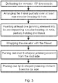
- Figure 3 shows schematically a flowchart with the sequence for masking the elevator (2) of the Horizontal Tail Plane (1) with a frisket (3).
- the sequence comprising the steps of:
- Figure 4 shows a sequence for masking the elevator (2) of the Horizontal Tail Plane (1), wherein at least one jamming element (4) is covered with the frisket (3).
- the sequence comprises the steps of:
- Figure 5 shows a schematic drawing of a tool-head robot (7) that comprises at least one robotic arm (7.1) connected at one end to a supporting base (7.3), and connected at the other end to at one six-axis head (7.2).
- the six-axis head (7.2) or hexapod comprises a 6-axis (XYZ, Pitch, Roll, Yaw) actuator for moving in each direction or around each rotation axis.
- the six-axis head (7.2) comprises a tool kit with the tool required to automatically perform the steps e) to h) of the method of masking the aeronautical structure according to a first inventive aspect of the invention.
- the supporting base (7.3) of the tool-head robot (7) is mounted on a rail (not shown in the figures) to allow displacement of the tool-head robot (7) rolling over stages in the assembly line.
- this displacement of the tool-head robot (7) rolling over stages in the assembly line may be performed by wheels on the supporting base (7.3) (not shown in the figures) following markers in the floor, preferably using Automatic Guided Vehicle technology.
- the tool-head robot (7) incorporates detecting means, e.g. object recognition tool, to avoid any clash with the aeronautical structure (1) that could cause damage thereto.
- Figure 6 shows schematically a flowchart with the sequence for automatically masking the elevator (2) of the Horizontal Tail Plane (1) with a frisket (3) by using a tool head robot (7.2). This sequence comprising the steps of:
Landscapes
- Engineering & Computer Science (AREA)
- Robotics (AREA)
- Mechanical Engineering (AREA)
- Manufacturing & Machinery (AREA)
- Transportation (AREA)
- Aviation & Aerospace Engineering (AREA)
- Application Of Or Painting With Fluid Materials (AREA)
Priority Applications (2)
| Application Number | Priority Date | Filing Date | Title |
|---|---|---|---|
| EP17382361.8A EP3427841A1 (de) | 2017-06-13 | 2017-06-13 | Maskierungsverfahren |
| US16/003,433 US20180354651A1 (en) | 2017-06-13 | 2018-06-08 | Masking method |
Applications Claiming Priority (1)
| Application Number | Priority Date | Filing Date | Title |
|---|---|---|---|
| EP17382361.8A EP3427841A1 (de) | 2017-06-13 | 2017-06-13 | Maskierungsverfahren |
Publications (1)
| Publication Number | Publication Date |
|---|---|
| EP3427841A1 true EP3427841A1 (de) | 2019-01-16 |
Family
ID=59091457
Family Applications (1)
| Application Number | Title | Priority Date | Filing Date |
|---|---|---|---|
| EP17382361.8A Withdrawn EP3427841A1 (de) | 2017-06-13 | 2017-06-13 | Maskierungsverfahren |
Country Status (2)
| Country | Link |
|---|---|
| US (1) | US20180354651A1 (de) |
| EP (1) | EP3427841A1 (de) |
Families Citing this family (1)
| Publication number | Priority date | Publication date | Assignee | Title |
|---|---|---|---|---|
| CN118594819B (zh) * | 2024-07-31 | 2024-11-05 | 江苏耐力森模具制造有限公司 | 一种氮气弹簧缸筒喷漆加工系统 |
Citations (3)
| Publication number | Priority date | Publication date | Assignee | Title |
|---|---|---|---|---|
| US2363841A (en) * | 1942-03-30 | 1944-11-28 | Duggan James Edward | Paint mask structure |
| US20130164448A1 (en) * | 2011-09-13 | 2013-06-27 | Heath Moore | Stenciling device and method |
| WO2016098036A1 (en) * | 2014-12-19 | 2016-06-23 | Alenia Aermacchi S.P.A. | Covering element and method for protecting a paint-sensitive area |
-
2017
- 2017-06-13 EP EP17382361.8A patent/EP3427841A1/de not_active Withdrawn
-
2018
- 2018-06-08 US US16/003,433 patent/US20180354651A1/en not_active Abandoned
Patent Citations (3)
| Publication number | Priority date | Publication date | Assignee | Title |
|---|---|---|---|---|
| US2363841A (en) * | 1942-03-30 | 1944-11-28 | Duggan James Edward | Paint mask structure |
| US20130164448A1 (en) * | 2011-09-13 | 2013-06-27 | Heath Moore | Stenciling device and method |
| WO2016098036A1 (en) * | 2014-12-19 | 2016-06-23 | Alenia Aermacchi S.P.A. | Covering element and method for protecting a paint-sensitive area |
Also Published As
| Publication number | Publication date |
|---|---|
| US20180354651A1 (en) | 2018-12-13 |
Similar Documents
| Publication | Publication Date | Title |
|---|---|---|
| RU2616477C2 (ru) | Устройство для клепки фюзеляжей летательных аппаратов | |
| EP2239088B1 (de) | Automatische Locherzeugung | |
| JP6690895B2 (ja) | 航空機構造の可動自動組立ツール | |
| CN101357687B (zh) | 一种基于工业机器人的多任务飞机辅助装配系统 | |
| EP2406134B1 (de) | Automatisiertes flügellackiersystem | |
| EP2957396B1 (de) | Roboterausrichtungssysteme und verfahren zur ausrichtung eines roboters | |
| EP2635429B1 (de) | Schablone und verfahren für schnelle verbundstoffreparatur | |
| EP2595862B1 (de) | Elektromagnetisches und/oder vakuumraupenmontagesystem zur bewegung und fixierung von arbeitswerkzeugen auf einer bogenförmigen fläche wie etwa ein flugzeugrumpf | |
| EP2865509B1 (de) | Selbstzentrierender Abdichtungsapplikator | |
| US20110000064A1 (en) | Method and apparatus for removing blind fasteners | |
| US10773830B2 (en) | Flexible track manufacturing system and method | |
| US9656319B2 (en) | Positioning system for electromagnetic riveting | |
| DE102017009356A1 (de) | Werkzeugmaschine | |
| EP3427841A1 (de) | Maskierungsverfahren | |
| US20110119919A1 (en) | Determinant Assembly System for Manufacturing Objects | |
| JP6920046B2 (ja) | フィルム切断用治具、及びフィルム施工方法 | |
| US10479529B2 (en) | Composite panel tool | |
| US20180154457A1 (en) | Method and system for defining the position of a fastener with a peen mark | |
| EP3263293B1 (de) | Analyse von endeffektoroperationen durch einen roboter | |
| WO2017047575A1 (ja) | ガイド装置およびスカーフ加工面形成方法 | |
| US10414026B2 (en) | Multi-functional debur tool | |
| EP3862172B1 (de) | Verbundplattewerkzeugsystem und verfahren | |
| EP2826590A1 (de) | Werkzeug zur dynamischen befestigung von zu bearbeitenden teilen | |
| EP3686105A1 (de) | Systeme und verfahren für oberflächenabdeckungen von flugzeugstrukturen | |
| Wilson | Robots in the aerospace industry |
Legal Events
| Date | Code | Title | Description |
|---|---|---|---|
| PUAI | Public reference made under article 153(3) epc to a published international application that has entered the european phase |
Free format text: ORIGINAL CODE: 0009012 |
|
| AK | Designated contracting states |
Kind code of ref document: A1 Designated state(s): AL AT BE BG CH CY CZ DE DK EE ES FI FR GB GR HR HU IE IS IT LI LT LU LV MC MK MT NL NO PL PT RO RS SE SI SK SM TR |
|
| AX | Request for extension of the european patent |
Extension state: BA ME |
|
| STAA | Information on the status of an ep patent application or granted ep patent |
Free format text: STATUS: THE APPLICATION IS DEEMED TO BE WITHDRAWN |
|
| 18D | Application deemed to be withdrawn |
Effective date: 20190717 |