EP3426197B1 - Apparatus for joint replacement arthroplasty - Google Patents
Apparatus for joint replacement arthroplasty Download PDFInfo
- Publication number
- EP3426197B1 EP3426197B1 EP17762640.5A EP17762640A EP3426197B1 EP 3426197 B1 EP3426197 B1 EP 3426197B1 EP 17762640 A EP17762640 A EP 17762640A EP 3426197 B1 EP3426197 B1 EP 3426197B1
- Authority
- EP
- European Patent Office
- Prior art keywords
- bone
- radial
- carpal
- joint
- carpal capitate
- Prior art date
- Legal status (The legal status is an assumption and is not a legal conclusion. Google has not performed a legal analysis and makes no representation as to the accuracy of the status listed.)
- Active
Links
- 238000011882 arthroplasty Methods 0.000 title description 6
- 210000000988 bone and bone Anatomy 0.000 claims description 124
- 210000002753 capitate bone Anatomy 0.000 claims description 69
- 210000000707 wrist Anatomy 0.000 claims description 63
- 230000033001 locomotion Effects 0.000 claims description 54
- 239000007943 implant Substances 0.000 claims description 48
- 230000001054 cortical effect Effects 0.000 claims description 33
- 238000002513 implantation Methods 0.000 claims description 28
- 210000000623 ulna Anatomy 0.000 claims description 24
- 238000003780 insertion Methods 0.000 claims description 9
- 230000037431 insertion Effects 0.000 claims description 9
- 229910052588 hydroxylapatite Inorganic materials 0.000 claims description 7
- 239000000463 material Substances 0.000 claims description 7
- XYJRXVWERLGGKC-UHFFFAOYSA-D pentacalcium;hydroxide;triphosphate Chemical compound [OH-].[Ca+2].[Ca+2].[Ca+2].[Ca+2].[Ca+2].[O-]P([O-])([O-])=O.[O-]P([O-])([O-])=O.[O-]P([O-])([O-])=O XYJRXVWERLGGKC-UHFFFAOYSA-D 0.000 claims description 7
- -1 polyethylene Polymers 0.000 claims description 7
- 239000004698 Polyethylene Substances 0.000 claims description 6
- 229920000573 polyethylene Polymers 0.000 claims description 6
- 229910052751 metal Inorganic materials 0.000 claims description 4
- 239000002184 metal Substances 0.000 claims description 4
- 239000000919 ceramic Substances 0.000 claims description 3
- 210000000845 cartilage Anatomy 0.000 description 29
- 210000000689 upper leg Anatomy 0.000 description 21
- 210000002303 tibia Anatomy 0.000 description 20
- 238000000034 method Methods 0.000 description 18
- 210000003010 carpal bone Anatomy 0.000 description 17
- 210000001503 joint Anatomy 0.000 description 16
- RTAQQCXQSZGOHL-UHFFFAOYSA-N Titanium Chemical compound [Ti] RTAQQCXQSZGOHL-UHFFFAOYSA-N 0.000 description 6
- 229910001220 stainless steel Inorganic materials 0.000 description 6
- 239000010935 stainless steel Substances 0.000 description 6
- 239000010936 titanium Substances 0.000 description 6
- 238000002271 resection Methods 0.000 description 5
- 210000003906 tibiofibular joint Anatomy 0.000 description 5
- 229910052719 titanium Inorganic materials 0.000 description 5
- 0 CC*(CCCC*=C)CCCCN* Chemical compound CC*(CCCC*=C)CCCCN* 0.000 description 4
- 230000008878 coupling Effects 0.000 description 4
- 238000010168 coupling process Methods 0.000 description 4
- 238000005859 coupling reaction Methods 0.000 description 4
- 238000012986 modification Methods 0.000 description 4
- 230000004048 modification Effects 0.000 description 4
- 230000007170 pathology Effects 0.000 description 4
- 230000008468 bone growth Effects 0.000 description 3
- 230000006378 damage Effects 0.000 description 3
- 210000002411 hand bone Anatomy 0.000 description 3
- 210000001699 lower leg Anatomy 0.000 description 3
- 210000003991 lunate bone Anatomy 0.000 description 3
- 230000015654 memory Effects 0.000 description 3
- 229920003023 plastic Polymers 0.000 description 3
- 239000004033 plastic Substances 0.000 description 3
- 210000003189 scaphoid bone Anatomy 0.000 description 3
- 210000004872 soft tissue Anatomy 0.000 description 3
- 210000003857 wrist joint Anatomy 0.000 description 3
- 208000037408 Device failure Diseases 0.000 description 2
- 206010037802 Radius fracture Diseases 0.000 description 2
- 230000006835 compression Effects 0.000 description 2
- 238000007906 compression Methods 0.000 description 2
- 238000010276 construction Methods 0.000 description 2
- 230000002708 enhancing effect Effects 0.000 description 2
- 210000000693 hamate bone Anatomy 0.000 description 2
- 238000001727 in vivo Methods 0.000 description 2
- 208000014674 injury Diseases 0.000 description 2
- 210000003127 knee Anatomy 0.000 description 2
- 210000000236 metacarpal bone Anatomy 0.000 description 2
- 210000000615 pisiform bone Anatomy 0.000 description 2
- 230000008569 process Effects 0.000 description 2
- 239000007787 solid Substances 0.000 description 2
- 238000006467 substitution reaction Methods 0.000 description 2
- 238000001356 surgical procedure Methods 0.000 description 2
- 210000001713 trapezium bone Anatomy 0.000 description 2
- 210000000266 trapezoid bone Anatomy 0.000 description 2
- 210000003053 triquetrum bone Anatomy 0.000 description 2
- 208000025978 Athletic injury Diseases 0.000 description 1
- 208000010392 Bone Fractures Diseases 0.000 description 1
- OHEZAPZSVNSTQF-UHFFFAOYSA-N C(C1CC2)C1C(CC1)C21C(C1)C2C1C1C3C2C3CC1 Chemical compound C(C1CC2)C1C(CC1)C21C(C1)C2C1C1C3C2C3CC1 OHEZAPZSVNSTQF-UHFFFAOYSA-N 0.000 description 1
- 229910001200 Ferrotitanium Inorganic materials 0.000 description 1
- 208000002658 Intra-Articular Fractures Diseases 0.000 description 1
- 206010041738 Sports injury Diseases 0.000 description 1
- 208000027418 Wounds and injury Diseases 0.000 description 1
- 238000013459 approach Methods 0.000 description 1
- 238000005452 bending Methods 0.000 description 1
- 210000003797 carpal joint Anatomy 0.000 description 1
- 210000000511 carpometacarpal joint Anatomy 0.000 description 1
- 239000003814 drug Substances 0.000 description 1
- 229940079593 drug Drugs 0.000 description 1
- 230000004064 dysfunction Effects 0.000 description 1
- 238000005516 engineering process Methods 0.000 description 1
- 210000004553 finger phalanx Anatomy 0.000 description 1
- 230000003116 impacting effect Effects 0.000 description 1
- 238000011065 in-situ storage Methods 0.000 description 1
- 210000000281 joint capsule Anatomy 0.000 description 1
- 230000037231 joint health Effects 0.000 description 1
- 210000000629 knee joint Anatomy 0.000 description 1
- 210000002414 leg Anatomy 0.000 description 1
- 238000002483 medication Methods 0.000 description 1
- 210000000811 metacarpophalangeal joint Anatomy 0.000 description 1
- 201000008482 osteoarthritis Diseases 0.000 description 1
- 238000004321 preservation Methods 0.000 description 1
- 230000002265 prevention Effects 0.000 description 1
- 238000012545 processing Methods 0.000 description 1
- 230000009467 reduction Effects 0.000 description 1
- 230000008439 repair process Effects 0.000 description 1
- 230000006641 stabilisation Effects 0.000 description 1
- 238000011105 stabilization Methods 0.000 description 1
- 230000000087 stabilizing effect Effects 0.000 description 1
- 238000003860 storage Methods 0.000 description 1
- 238000002560 therapeutic procedure Methods 0.000 description 1
- 210000001519 tissue Anatomy 0.000 description 1
- 230000008733 trauma Effects 0.000 description 1
Images


Classifications
-
- A—HUMAN NECESSITIES
- A61—MEDICAL OR VETERINARY SCIENCE; HYGIENE
- A61F—FILTERS IMPLANTABLE INTO BLOOD VESSELS; PROSTHESES; DEVICES PROVIDING PATENCY TO, OR PREVENTING COLLAPSING OF, TUBULAR STRUCTURES OF THE BODY, e.g. STENTS; ORTHOPAEDIC, NURSING OR CONTRACEPTIVE DEVICES; FOMENTATION; TREATMENT OR PROTECTION OF EYES OR EARS; BANDAGES, DRESSINGS OR ABSORBENT PADS; FIRST-AID KITS
- A61F2/00—Filters implantable into blood vessels; Prostheses, i.e. artificial substitutes or replacements for parts of the body; Appliances for connecting them with the body; Devices providing patency to, or preventing collapsing of, tubular structures of the body, e.g. stents
- A61F2/02—Prostheses implantable into the body
- A61F2/30—Joints
- A61F2/42—Joints for wrists or ankles; for hands, e.g. fingers; for feet, e.g. toes
- A61F2/4261—Joints for wrists or ankles; for hands, e.g. fingers; for feet, e.g. toes for wrists
-
- A—HUMAN NECESSITIES
- A61—MEDICAL OR VETERINARY SCIENCE; HYGIENE
- A61B—DIAGNOSIS; SURGERY; IDENTIFICATION
- A61B17/00—Surgical instruments, devices or methods, e.g. tourniquets
- A61B17/56—Surgical instruments or methods for treatment of bones or joints; Devices specially adapted therefor
- A61B17/58—Surgical instruments or methods for treatment of bones or joints; Devices specially adapted therefor for osteosynthesis, e.g. bone plates, screws, setting implements or the like
- A61B17/68—Internal fixation devices, including fasteners and spinal fixators, even if a part thereof projects from the skin
- A61B17/80—Cortical plates, i.e. bone plates; Instruments for holding or positioning cortical plates, or for compressing bones attached to cortical plates
- A61B17/8061—Cortical plates, i.e. bone plates; Instruments for holding or positioning cortical plates, or for compressing bones attached to cortical plates specially adapted for particular bones
-
- A—HUMAN NECESSITIES
- A61—MEDICAL OR VETERINARY SCIENCE; HYGIENE
- A61B—DIAGNOSIS; SURGERY; IDENTIFICATION
- A61B17/00—Surgical instruments, devices or methods, e.g. tourniquets
- A61B17/56—Surgical instruments or methods for treatment of bones or joints; Devices specially adapted therefor
- A61B17/58—Surgical instruments or methods for treatment of bones or joints; Devices specially adapted therefor for osteosynthesis, e.g. bone plates, screws, setting implements or the like
- A61B17/68—Internal fixation devices, including fasteners and spinal fixators, even if a part thereof projects from the skin
- A61B17/80—Cortical plates, i.e. bone plates; Instruments for holding or positioning cortical plates, or for compressing bones attached to cortical plates
- A61B17/809—Cortical plates, i.e. bone plates; Instruments for holding or positioning cortical plates, or for compressing bones attached to cortical plates with bone-penetrating elements, e.g. blades or prongs
-
- A—HUMAN NECESSITIES
- A61—MEDICAL OR VETERINARY SCIENCE; HYGIENE
- A61B—DIAGNOSIS; SURGERY; IDENTIFICATION
- A61B17/00—Surgical instruments, devices or methods, e.g. tourniquets
- A61B17/56—Surgical instruments or methods for treatment of bones or joints; Devices specially adapted therefor
- A61B17/58—Surgical instruments or methods for treatment of bones or joints; Devices specially adapted therefor for osteosynthesis, e.g. bone plates, screws, setting implements or the like
- A61B17/68—Internal fixation devices, including fasteners and spinal fixators, even if a part thereof projects from the skin
- A61B17/84—Fasteners therefor or fasteners being internal fixation devices
- A61B17/86—Pins or screws or threaded wires; nuts therefor
-
- A—HUMAN NECESSITIES
- A61—MEDICAL OR VETERINARY SCIENCE; HYGIENE
- A61F—FILTERS IMPLANTABLE INTO BLOOD VESSELS; PROSTHESES; DEVICES PROVIDING PATENCY TO, OR PREVENTING COLLAPSING OF, TUBULAR STRUCTURES OF THE BODY, e.g. STENTS; ORTHOPAEDIC, NURSING OR CONTRACEPTIVE DEVICES; FOMENTATION; TREATMENT OR PROTECTION OF EYES OR EARS; BANDAGES, DRESSINGS OR ABSORBENT PADS; FIRST-AID KITS
- A61F2/00—Filters implantable into blood vessels; Prostheses, i.e. artificial substitutes or replacements for parts of the body; Appliances for connecting them with the body; Devices providing patency to, or preventing collapsing of, tubular structures of the body, e.g. stents
- A61F2/02—Prostheses implantable into the body
- A61F2/30—Joints
- A61F2002/30001—Additional features of subject-matter classified in A61F2/28, A61F2/30 and subgroups thereof
- A61F2002/30108—Shapes
- A61F2002/3011—Cross-sections or two-dimensional shapes
- A61F2002/30112—Rounded shapes, e.g. with rounded corners
- A61F2002/30131—Rounded shapes, e.g. with rounded corners horseshoe- or crescent- or C-shaped or U-shaped
-
- A—HUMAN NECESSITIES
- A61—MEDICAL OR VETERINARY SCIENCE; HYGIENE
- A61F—FILTERS IMPLANTABLE INTO BLOOD VESSELS; PROSTHESES; DEVICES PROVIDING PATENCY TO, OR PREVENTING COLLAPSING OF, TUBULAR STRUCTURES OF THE BODY, e.g. STENTS; ORTHOPAEDIC, NURSING OR CONTRACEPTIVE DEVICES; FOMENTATION; TREATMENT OR PROTECTION OF EYES OR EARS; BANDAGES, DRESSINGS OR ABSORBENT PADS; FIRST-AID KITS
- A61F2/00—Filters implantable into blood vessels; Prostheses, i.e. artificial substitutes or replacements for parts of the body; Appliances for connecting them with the body; Devices providing patency to, or preventing collapsing of, tubular structures of the body, e.g. stents
- A61F2/02—Prostheses implantable into the body
- A61F2/30—Joints
- A61F2002/30001—Additional features of subject-matter classified in A61F2/28, A61F2/30 and subgroups thereof
- A61F2002/30108—Shapes
- A61F2002/3011—Cross-sections or two-dimensional shapes
- A61F2002/30138—Convex polygonal shapes
- A61F2002/30156—Convex polygonal shapes triangular
-
- A—HUMAN NECESSITIES
- A61—MEDICAL OR VETERINARY SCIENCE; HYGIENE
- A61F—FILTERS IMPLANTABLE INTO BLOOD VESSELS; PROSTHESES; DEVICES PROVIDING PATENCY TO, OR PREVENTING COLLAPSING OF, TUBULAR STRUCTURES OF THE BODY, e.g. STENTS; ORTHOPAEDIC, NURSING OR CONTRACEPTIVE DEVICES; FOMENTATION; TREATMENT OR PROTECTION OF EYES OR EARS; BANDAGES, DRESSINGS OR ABSORBENT PADS; FIRST-AID KITS
- A61F2/00—Filters implantable into blood vessels; Prostheses, i.e. artificial substitutes or replacements for parts of the body; Appliances for connecting them with the body; Devices providing patency to, or preventing collapsing of, tubular structures of the body, e.g. stents
- A61F2/02—Prostheses implantable into the body
- A61F2/30—Joints
- A61F2002/30001—Additional features of subject-matter classified in A61F2/28, A61F2/30 and subgroups thereof
- A61F2002/30108—Shapes
- A61F2002/3011—Cross-sections or two-dimensional shapes
- A61F2002/30182—Other shapes
- A61F2002/30192—J-shaped
-
- A—HUMAN NECESSITIES
- A61—MEDICAL OR VETERINARY SCIENCE; HYGIENE
- A61F—FILTERS IMPLANTABLE INTO BLOOD VESSELS; PROSTHESES; DEVICES PROVIDING PATENCY TO, OR PREVENTING COLLAPSING OF, TUBULAR STRUCTURES OF THE BODY, e.g. STENTS; ORTHOPAEDIC, NURSING OR CONTRACEPTIVE DEVICES; FOMENTATION; TREATMENT OR PROTECTION OF EYES OR EARS; BANDAGES, DRESSINGS OR ABSORBENT PADS; FIRST-AID KITS
- A61F2/00—Filters implantable into blood vessels; Prostheses, i.e. artificial substitutes or replacements for parts of the body; Appliances for connecting them with the body; Devices providing patency to, or preventing collapsing of, tubular structures of the body, e.g. stents
- A61F2/02—Prostheses implantable into the body
- A61F2/30—Joints
- A61F2002/30001—Additional features of subject-matter classified in A61F2/28, A61F2/30 and subgroups thereof
- A61F2002/30316—The prosthesis having different structural features at different locations within the same prosthesis; Connections between prosthetic parts; Special structural features of bone or joint prostheses not otherwise provided for
- A61F2002/30329—Connections or couplings between prosthetic parts, e.g. between modular parts; Connecting elements
- A61F2002/30383—Connections or couplings between prosthetic parts, e.g. between modular parts; Connecting elements made by laterally inserting a protrusion, e.g. a rib into a complementarily-shaped groove
- A61F2002/30387—Dovetail connection
-
- A—HUMAN NECESSITIES
- A61—MEDICAL OR VETERINARY SCIENCE; HYGIENE
- A61F—FILTERS IMPLANTABLE INTO BLOOD VESSELS; PROSTHESES; DEVICES PROVIDING PATENCY TO, OR PREVENTING COLLAPSING OF, TUBULAR STRUCTURES OF THE BODY, e.g. STENTS; ORTHOPAEDIC, NURSING OR CONTRACEPTIVE DEVICES; FOMENTATION; TREATMENT OR PROTECTION OF EYES OR EARS; BANDAGES, DRESSINGS OR ABSORBENT PADS; FIRST-AID KITS
- A61F2/00—Filters implantable into blood vessels; Prostheses, i.e. artificial substitutes or replacements for parts of the body; Appliances for connecting them with the body; Devices providing patency to, or preventing collapsing of, tubular structures of the body, e.g. stents
- A61F2/02—Prostheses implantable into the body
- A61F2/30—Joints
- A61F2002/30001—Additional features of subject-matter classified in A61F2/28, A61F2/30 and subgroups thereof
- A61F2002/30316—The prosthesis having different structural features at different locations within the same prosthesis; Connections between prosthetic parts; Special structural features of bone or joint prostheses not otherwise provided for
- A61F2002/30329—Connections or couplings between prosthetic parts, e.g. between modular parts; Connecting elements
- A61F2002/30405—Connections or couplings between prosthetic parts, e.g. between modular parts; Connecting elements made by screwing complementary threads machined on the parts themselves
-
- A—HUMAN NECESSITIES
- A61—MEDICAL OR VETERINARY SCIENCE; HYGIENE
- A61F—FILTERS IMPLANTABLE INTO BLOOD VESSELS; PROSTHESES; DEVICES PROVIDING PATENCY TO, OR PREVENTING COLLAPSING OF, TUBULAR STRUCTURES OF THE BODY, e.g. STENTS; ORTHOPAEDIC, NURSING OR CONTRACEPTIVE DEVICES; FOMENTATION; TREATMENT OR PROTECTION OF EYES OR EARS; BANDAGES, DRESSINGS OR ABSORBENT PADS; FIRST-AID KITS
- A61F2/00—Filters implantable into blood vessels; Prostheses, i.e. artificial substitutes or replacements for parts of the body; Appliances for connecting them with the body; Devices providing patency to, or preventing collapsing of, tubular structures of the body, e.g. stents
- A61F2/02—Prostheses implantable into the body
- A61F2/30—Joints
- A61F2002/30001—Additional features of subject-matter classified in A61F2/28, A61F2/30 and subgroups thereof
- A61F2002/30316—The prosthesis having different structural features at different locations within the same prosthesis; Connections between prosthetic parts; Special structural features of bone or joint prostheses not otherwise provided for
- A61F2002/30329—Connections or couplings between prosthetic parts, e.g. between modular parts; Connecting elements
- A61F2002/30471—Connections or couplings between prosthetic parts, e.g. between modular parts; Connecting elements connected by a hinged linkage mechanism, e.g. of the single-bar or multi-bar linkage type
-
- A—HUMAN NECESSITIES
- A61—MEDICAL OR VETERINARY SCIENCE; HYGIENE
- A61F—FILTERS IMPLANTABLE INTO BLOOD VESSELS; PROSTHESES; DEVICES PROVIDING PATENCY TO, OR PREVENTING COLLAPSING OF, TUBULAR STRUCTURES OF THE BODY, e.g. STENTS; ORTHOPAEDIC, NURSING OR CONTRACEPTIVE DEVICES; FOMENTATION; TREATMENT OR PROTECTION OF EYES OR EARS; BANDAGES, DRESSINGS OR ABSORBENT PADS; FIRST-AID KITS
- A61F2/00—Filters implantable into blood vessels; Prostheses, i.e. artificial substitutes or replacements for parts of the body; Appliances for connecting them with the body; Devices providing patency to, or preventing collapsing of, tubular structures of the body, e.g. stents
- A61F2/02—Prostheses implantable into the body
- A61F2/30—Joints
- A61F2002/30001—Additional features of subject-matter classified in A61F2/28, A61F2/30 and subgroups thereof
- A61F2002/30316—The prosthesis having different structural features at different locations within the same prosthesis; Connections between prosthetic parts; Special structural features of bone or joint prostheses not otherwise provided for
- A61F2002/30329—Connections or couplings between prosthetic parts, e.g. between modular parts; Connecting elements
- A61F2002/30476—Connections or couplings between prosthetic parts, e.g. between modular parts; Connecting elements locked by an additional locking mechanism
- A61F2002/305—Snap connection
-
- A—HUMAN NECESSITIES
- A61—MEDICAL OR VETERINARY SCIENCE; HYGIENE
- A61F—FILTERS IMPLANTABLE INTO BLOOD VESSELS; PROSTHESES; DEVICES PROVIDING PATENCY TO, OR PREVENTING COLLAPSING OF, TUBULAR STRUCTURES OF THE BODY, e.g. STENTS; ORTHOPAEDIC, NURSING OR CONTRACEPTIVE DEVICES; FOMENTATION; TREATMENT OR PROTECTION OF EYES OR EARS; BANDAGES, DRESSINGS OR ABSORBENT PADS; FIRST-AID KITS
- A61F2/00—Filters implantable into blood vessels; Prostheses, i.e. artificial substitutes or replacements for parts of the body; Appliances for connecting them with the body; Devices providing patency to, or preventing collapsing of, tubular structures of the body, e.g. stents
- A61F2/02—Prostheses implantable into the body
- A61F2/30—Joints
- A61F2002/30001—Additional features of subject-matter classified in A61F2/28, A61F2/30 and subgroups thereof
- A61F2002/30316—The prosthesis having different structural features at different locations within the same prosthesis; Connections between prosthetic parts; Special structural features of bone or joint prostheses not otherwise provided for
- A61F2002/30535—Special structural features of bone or joint prostheses not otherwise provided for
- A61F2002/30576—Special structural features of bone or joint prostheses not otherwise provided for with extending fixation tabs
- A61F2002/30578—Special structural features of bone or joint prostheses not otherwise provided for with extending fixation tabs having apertures, e.g. for receiving fixation screws
-
- A—HUMAN NECESSITIES
- A61—MEDICAL OR VETERINARY SCIENCE; HYGIENE
- A61F—FILTERS IMPLANTABLE INTO BLOOD VESSELS; PROSTHESES; DEVICES PROVIDING PATENCY TO, OR PREVENTING COLLAPSING OF, TUBULAR STRUCTURES OF THE BODY, e.g. STENTS; ORTHOPAEDIC, NURSING OR CONTRACEPTIVE DEVICES; FOMENTATION; TREATMENT OR PROTECTION OF EYES OR EARS; BANDAGES, DRESSINGS OR ABSORBENT PADS; FIRST-AID KITS
- A61F2/00—Filters implantable into blood vessels; Prostheses, i.e. artificial substitutes or replacements for parts of the body; Appliances for connecting them with the body; Devices providing patency to, or preventing collapsing of, tubular structures of the body, e.g. stents
- A61F2/02—Prostheses implantable into the body
- A61F2/30—Joints
- A61F2002/30001—Additional features of subject-matter classified in A61F2/28, A61F2/30 and subgroups thereof
- A61F2002/30316—The prosthesis having different structural features at different locations within the same prosthesis; Connections between prosthetic parts; Special structural features of bone or joint prostheses not otherwise provided for
- A61F2002/30535—Special structural features of bone or joint prostheses not otherwise provided for
- A61F2002/30604—Special structural features of bone or joint prostheses not otherwise provided for modular
-
- A—HUMAN NECESSITIES
- A61—MEDICAL OR VETERINARY SCIENCE; HYGIENE
- A61F—FILTERS IMPLANTABLE INTO BLOOD VESSELS; PROSTHESES; DEVICES PROVIDING PATENCY TO, OR PREVENTING COLLAPSING OF, TUBULAR STRUCTURES OF THE BODY, e.g. STENTS; ORTHOPAEDIC, NURSING OR CONTRACEPTIVE DEVICES; FOMENTATION; TREATMENT OR PROTECTION OF EYES OR EARS; BANDAGES, DRESSINGS OR ABSORBENT PADS; FIRST-AID KITS
- A61F2/00—Filters implantable into blood vessels; Prostheses, i.e. artificial substitutes or replacements for parts of the body; Appliances for connecting them with the body; Devices providing patency to, or preventing collapsing of, tubular structures of the body, e.g. stents
- A61F2/02—Prostheses implantable into the body
- A61F2/30—Joints
- A61F2/30767—Special external or bone-contacting surface, e.g. coating for improving bone ingrowth
- A61F2/30771—Special external or bone-contacting surface, e.g. coating for improving bone ingrowth applied in original prostheses, e.g. holes or grooves
- A61F2002/30878—Special external or bone-contacting surface, e.g. coating for improving bone ingrowth applied in original prostheses, e.g. holes or grooves with non-sharp protrusions, for instance contacting the bone for anchoring, e.g. keels, pegs, pins, posts, shanks, stems, struts
- A61F2002/30899—Protrusions pierced with apertures
-
- A—HUMAN NECESSITIES
- A61—MEDICAL OR VETERINARY SCIENCE; HYGIENE
- A61F—FILTERS IMPLANTABLE INTO BLOOD VESSELS; PROSTHESES; DEVICES PROVIDING PATENCY TO, OR PREVENTING COLLAPSING OF, TUBULAR STRUCTURES OF THE BODY, e.g. STENTS; ORTHOPAEDIC, NURSING OR CONTRACEPTIVE DEVICES; FOMENTATION; TREATMENT OR PROTECTION OF EYES OR EARS; BANDAGES, DRESSINGS OR ABSORBENT PADS; FIRST-AID KITS
- A61F2/00—Filters implantable into blood vessels; Prostheses, i.e. artificial substitutes or replacements for parts of the body; Appliances for connecting them with the body; Devices providing patency to, or preventing collapsing of, tubular structures of the body, e.g. stents
- A61F2/02—Prostheses implantable into the body
- A61F2/30—Joints
- A61F2/42—Joints for wrists or ankles; for hands, e.g. fingers; for feet, e.g. toes
- A61F2/4261—Joints for wrists or ankles; for hands, e.g. fingers; for feet, e.g. toes for wrists
- A61F2002/4264—Joints for wrists or ankles; for hands, e.g. fingers; for feet, e.g. toes for wrists for radio-carpal joints
-
- A—HUMAN NECESSITIES
- A61—MEDICAL OR VETERINARY SCIENCE; HYGIENE
- A61F—FILTERS IMPLANTABLE INTO BLOOD VESSELS; PROSTHESES; DEVICES PROVIDING PATENCY TO, OR PREVENTING COLLAPSING OF, TUBULAR STRUCTURES OF THE BODY, e.g. STENTS; ORTHOPAEDIC, NURSING OR CONTRACEPTIVE DEVICES; FOMENTATION; TREATMENT OR PROTECTION OF EYES OR EARS; BANDAGES, DRESSINGS OR ABSORBENT PADS; FIRST-AID KITS
- A61F2/00—Filters implantable into blood vessels; Prostheses, i.e. artificial substitutes or replacements for parts of the body; Appliances for connecting them with the body; Devices providing patency to, or preventing collapsing of, tubular structures of the body, e.g. stents
- A61F2/02—Prostheses implantable into the body
- A61F2/30—Joints
- A61F2/42—Joints for wrists or ankles; for hands, e.g. fingers; for feet, e.g. toes
- A61F2/4261—Joints for wrists or ankles; for hands, e.g. fingers; for feet, e.g. toes for wrists
- A61F2002/4266—Joints for wrists or ankles; for hands, e.g. fingers; for feet, e.g. toes for wrists for ulno-carpal joints
-
- A—HUMAN NECESSITIES
- A61—MEDICAL OR VETERINARY SCIENCE; HYGIENE
- A61F—FILTERS IMPLANTABLE INTO BLOOD VESSELS; PROSTHESES; DEVICES PROVIDING PATENCY TO, OR PREVENTING COLLAPSING OF, TUBULAR STRUCTURES OF THE BODY, e.g. STENTS; ORTHOPAEDIC, NURSING OR CONTRACEPTIVE DEVICES; FOMENTATION; TREATMENT OR PROTECTION OF EYES OR EARS; BANDAGES, DRESSINGS OR ABSORBENT PADS; FIRST-AID KITS
- A61F2/00—Filters implantable into blood vessels; Prostheses, i.e. artificial substitutes or replacements for parts of the body; Appliances for connecting them with the body; Devices providing patency to, or preventing collapsing of, tubular structures of the body, e.g. stents
- A61F2/02—Prostheses implantable into the body
- A61F2/30—Joints
- A61F2/42—Joints for wrists or ankles; for hands, e.g. fingers; for feet, e.g. toes
- A61F2/4261—Joints for wrists or ankles; for hands, e.g. fingers; for feet, e.g. toes for wrists
- A61F2002/4269—Joints for wrists or ankles; for hands, e.g. fingers; for feet, e.g. toes for wrists for distal radio-ulnar joints, i.e. DRU joints
-
- A—HUMAN NECESSITIES
- A61—MEDICAL OR VETERINARY SCIENCE; HYGIENE
- A61F—FILTERS IMPLANTABLE INTO BLOOD VESSELS; PROSTHESES; DEVICES PROVIDING PATENCY TO, OR PREVENTING COLLAPSING OF, TUBULAR STRUCTURES OF THE BODY, e.g. STENTS; ORTHOPAEDIC, NURSING OR CONTRACEPTIVE DEVICES; FOMENTATION; TREATMENT OR PROTECTION OF EYES OR EARS; BANDAGES, DRESSINGS OR ABSORBENT PADS; FIRST-AID KITS
- A61F2/00—Filters implantable into blood vessels; Prostheses, i.e. artificial substitutes or replacements for parts of the body; Appliances for connecting them with the body; Devices providing patency to, or preventing collapsing of, tubular structures of the body, e.g. stents
- A61F2/02—Prostheses implantable into the body
- A61F2/30—Joints
- A61F2/42—Joints for wrists or ankles; for hands, e.g. fingers; for feet, e.g. toes
- A61F2/4261—Joints for wrists or ankles; for hands, e.g. fingers; for feet, e.g. toes for wrists
- A61F2002/4271—Carpal bones
- A61F2002/4274—Distal carpal row, i.e. bones adjacent the metacarpal bones
- A61F2002/4282—Capitate
-
- A—HUMAN NECESSITIES
- A61—MEDICAL OR VETERINARY SCIENCE; HYGIENE
- A61F—FILTERS IMPLANTABLE INTO BLOOD VESSELS; PROSTHESES; DEVICES PROVIDING PATENCY TO, OR PREVENTING COLLAPSING OF, TUBULAR STRUCTURES OF THE BODY, e.g. STENTS; ORTHOPAEDIC, NURSING OR CONTRACEPTIVE DEVICES; FOMENTATION; TREATMENT OR PROTECTION OF EYES OR EARS; BANDAGES, DRESSINGS OR ABSORBENT PADS; FIRST-AID KITS
- A61F2/00—Filters implantable into blood vessels; Prostheses, i.e. artificial substitutes or replacements for parts of the body; Appliances for connecting them with the body; Devices providing patency to, or preventing collapsing of, tubular structures of the body, e.g. stents
- A61F2/02—Prostheses implantable into the body
- A61F2/30—Joints
- A61F2/42—Joints for wrists or ankles; for hands, e.g. fingers; for feet, e.g. toes
- A61F2/4261—Joints for wrists or ankles; for hands, e.g. fingers; for feet, e.g. toes for wrists
- A61F2002/4271—Carpal bones
- A61F2002/4287—Proximal carpal row, i.e. bones adjacent the radius and the ulna
- A61F2002/4292—Lunate
-
- A—HUMAN NECESSITIES
- A61—MEDICAL OR VETERINARY SCIENCE; HYGIENE
- A61F—FILTERS IMPLANTABLE INTO BLOOD VESSELS; PROSTHESES; DEVICES PROVIDING PATENCY TO, OR PREVENTING COLLAPSING OF, TUBULAR STRUCTURES OF THE BODY, e.g. STENTS; ORTHOPAEDIC, NURSING OR CONTRACEPTIVE DEVICES; FOMENTATION; TREATMENT OR PROTECTION OF EYES OR EARS; BANDAGES, DRESSINGS OR ABSORBENT PADS; FIRST-AID KITS
- A61F2230/00—Geometry of prostheses classified in groups A61F2/00 - A61F2/26 or A61F2/82 or A61F9/00 or A61F11/00 or subgroups thereof
- A61F2230/0002—Two-dimensional shapes, e.g. cross-sections
- A61F2230/0004—Rounded shapes, e.g. with rounded corners
- A61F2230/0013—Horseshoe-shaped, e.g. crescent-shaped, C-shaped, U-shaped
-
- A—HUMAN NECESSITIES
- A61—MEDICAL OR VETERINARY SCIENCE; HYGIENE
- A61F—FILTERS IMPLANTABLE INTO BLOOD VESSELS; PROSTHESES; DEVICES PROVIDING PATENCY TO, OR PREVENTING COLLAPSING OF, TUBULAR STRUCTURES OF THE BODY, e.g. STENTS; ORTHOPAEDIC, NURSING OR CONTRACEPTIVE DEVICES; FOMENTATION; TREATMENT OR PROTECTION OF EYES OR EARS; BANDAGES, DRESSINGS OR ABSORBENT PADS; FIRST-AID KITS
- A61F2230/00—Geometry of prostheses classified in groups A61F2/00 - A61F2/26 or A61F2/82 or A61F9/00 or A61F11/00 or subgroups thereof
- A61F2230/0002—Two-dimensional shapes, e.g. cross-sections
- A61F2230/0028—Shapes in the form of latin or greek characters
- A61F2230/0054—V-shaped
-
- A—HUMAN NECESSITIES
- A61—MEDICAL OR VETERINARY SCIENCE; HYGIENE
- A61F—FILTERS IMPLANTABLE INTO BLOOD VESSELS; PROSTHESES; DEVICES PROVIDING PATENCY TO, OR PREVENTING COLLAPSING OF, TUBULAR STRUCTURES OF THE BODY, e.g. STENTS; ORTHOPAEDIC, NURSING OR CONTRACEPTIVE DEVICES; FOMENTATION; TREATMENT OR PROTECTION OF EYES OR EARS; BANDAGES, DRESSINGS OR ABSORBENT PADS; FIRST-AID KITS
- A61F2310/00—Prostheses classified in A61F2/28 or A61F2/30 - A61F2/44 being constructed from or coated with a particular material
- A61F2310/00005—The prosthesis being constructed from a particular material
- A61F2310/00011—Metals or alloys
- A61F2310/00017—Iron- or Fe-based alloys, e.g. stainless steel
-
- A—HUMAN NECESSITIES
- A61—MEDICAL OR VETERINARY SCIENCE; HYGIENE
- A61F—FILTERS IMPLANTABLE INTO BLOOD VESSELS; PROSTHESES; DEVICES PROVIDING PATENCY TO, OR PREVENTING COLLAPSING OF, TUBULAR STRUCTURES OF THE BODY, e.g. STENTS; ORTHOPAEDIC, NURSING OR CONTRACEPTIVE DEVICES; FOMENTATION; TREATMENT OR PROTECTION OF EYES OR EARS; BANDAGES, DRESSINGS OR ABSORBENT PADS; FIRST-AID KITS
- A61F2310/00—Prostheses classified in A61F2/28 or A61F2/30 - A61F2/44 being constructed from or coated with a particular material
- A61F2310/00005—The prosthesis being constructed from a particular material
- A61F2310/00011—Metals or alloys
- A61F2310/00023—Titanium or titanium-based alloys, e.g. Ti-Ni alloys
-
- A—HUMAN NECESSITIES
- A61—MEDICAL OR VETERINARY SCIENCE; HYGIENE
- A61F—FILTERS IMPLANTABLE INTO BLOOD VESSELS; PROSTHESES; DEVICES PROVIDING PATENCY TO, OR PREVENTING COLLAPSING OF, TUBULAR STRUCTURES OF THE BODY, e.g. STENTS; ORTHOPAEDIC, NURSING OR CONTRACEPTIVE DEVICES; FOMENTATION; TREATMENT OR PROTECTION OF EYES OR EARS; BANDAGES, DRESSINGS OR ABSORBENT PADS; FIRST-AID KITS
- A61F2310/00—Prostheses classified in A61F2/28 or A61F2/30 - A61F2/44 being constructed from or coated with a particular material
- A61F2310/00005—The prosthesis being constructed from a particular material
- A61F2310/00161—Carbon; Graphite
-
- A—HUMAN NECESSITIES
- A61—MEDICAL OR VETERINARY SCIENCE; HYGIENE
- A61F—FILTERS IMPLANTABLE INTO BLOOD VESSELS; PROSTHESES; DEVICES PROVIDING PATENCY TO, OR PREVENTING COLLAPSING OF, TUBULAR STRUCTURES OF THE BODY, e.g. STENTS; ORTHOPAEDIC, NURSING OR CONTRACEPTIVE DEVICES; FOMENTATION; TREATMENT OR PROTECTION OF EYES OR EARS; BANDAGES, DRESSINGS OR ABSORBENT PADS; FIRST-AID KITS
- A61F2310/00—Prostheses classified in A61F2/28 or A61F2/30 - A61F2/44 being constructed from or coated with a particular material
- A61F2310/00005—The prosthesis being constructed from a particular material
- A61F2310/00179—Ceramics or ceramic-like structures
Description
- The present invention relates to medical implants. More specifically, the present invention relates to an apparatus for joint replacement arthroplasty. The closest prior art is document
US 2012/0136453 A1 , which defines the preamble of claim 1. - A human joint is an interface that bridges two or more bones, and permits a variety of movements between the two or more bones at the joint. A wrist joint, or a knee joint, for example, include bones that intercommunicate in a common synovial cavity. Wrist articulations work together to allow for a wide range of motions in the joint. Most of the wrist motion, for example, occurs in the radiocarpal joint (RCJ) and the distal radioulnar joint (DRUJ). Most of the knee motion occurs in the tibiofemoral joint.
- Different joint pathologies may occur in the bones or joints resulting from conditions such as osteoarthritis, or from traumas, such as bone fractures, for example. A patient, or subject, with these joint pathologies may experience severe pain during movements of the joint ranging to severe disabilities due to limitations in joint movements.
- When severe joint pathologies occur, therapeutic methods such as the use of medications may not alleviate the pain and movement limitations in the joints of the patient. Partial or full joint replacement arthroplasty may be the best course of treatment for the patient.
- The present invention is defined in claim 1 and concerns a radiocarpal joint replacement apparatus for implantation in a wrist of a subject, including a radial member configured to be affixed to a portion of an end of the radial bone proximal to the wrist including a fixture to be affixed over a longitudinal aspect of the radial bone and a radial resurfacing plate having a substantially concave surface configured to be located at the end of the radial bone, a carpal capitate bone insert configured to be inserted and affixed into the carpal capitate bone, and a bulbous component comprising a first convex head and a second convex head, substantially opposite each other and connected by a neck defining an annular groove between the first convex head and the second convex head, wherein the carpal capitate bone insert is configured to be flexibly coupled to the first convex head of the bulbous component, and wherein the radial resurfacing plate of the radial member with the concave surface is configured to be operably coupled to the second convex head of the bulbous component so as to allow radial freedom of motion of the carpal capitate member with respect to the radial resurfacing plate after the implantation.
- Furthermore, in accordance with some embodiments of the present invention, the carpal capitate bone insert includes a dorsal cortical plate and an intraosseous stem, the intraosseous stem inserted into the carpal capitate bone, and the carpal capitate bone insert is affixed to the carpal capitate bone with screws inserted through holes in the dorsal cortical plate and the intraosseous stem.
- Furthermore, in accordance with some embodiments of the present invention, the carpal capitate bone insert includes a screw threaded into the carpal capitate bone so as to affix the carpal capitate insert to the carpal capitate bone.
- Furthermore, in accordance with some embodiments of the present invention, the carpal capitate bone insert includes petals configured to be inserted into the annular grove so as to flexibly hold the bulbous component to the carpal capitate bone insert.
- Furthermore, in accordance with some embodiments of the present invention, the carpal capitate bone insert includes an implant insertion element coated with hydroxylapatite.
- Furthermore, in accordance with some embodiments of the present invention, the bulbous component is formed from a material selected from the group consisting of polyethylene, ceramic, and pyrocarbon.
- Furthermore, in accordance with some embodiments of the present invention, the radial resurfacing plate is formed from a polished metal surface.
- Furthermore, in accordance with some embodiments of the present invention, the fixture is V-shaped.
- Furthermore, in accordance with some embodiments of the present invention, the radiocarpal joint replacement apparatus, includes a hook formed on the radial member facing the ulna bone and proximal to the wrist, and an ulnar member configured to be affixed to a portion of an end of the ulna bone proximal to the wrist and opposite to the hook, the ulnar member including a bore configured to receive hook, and retain the hook after implantation, wherein the bore is shaped to allow relative movement between the radial bone and the ulna bone so as to facilitate supination and pronation movement of the wrist of the subject.
- Furthermore, in accordance with some embodiments of the present invention, the ulnar member is formed from a receptacle piece and a mounting piece.
- Furthermore, in accordance with some embodiments of the present invention, the bore is C-shaped.
- There is further provided in the present disclosure details of a distal radioulnar joint replacement apparatus for implantation in a wrist of a subject, including a sigmoidal member configured to be affixed onto a portion of an end of the radial bone proximal to the wrist including a lower mounting bracket to be affixed over a longitudinal aspect of the radial bone so as to face the ulna bone, the sigmoidal member including a hook, and an ulnar member configured to be affixed to a portion of an end of the ulna bone proximal to the wrist and opposite to the sigmoidal member, the ulnar member including a bore configured to receive hook, and retain the hook after implantation, wherein the bore is shaped so as to allow relative movement between the radial bone and the ulna bone so as to facilitate supination and pronation movement of the wrist of the subject.
- Furthermore, the sigmoidal member includes a triangular peg implanted into cancellous bone at the end of the radius bone.
- Furthermore, the bore is C-shaped.
- Furthermore, the ulnar member is formed from a receptacle piece and a mounting piece.
- Furthermore, the receptacle piece is formed from a material selected from the group consisting of mobile polyethylene and pyrocarbon, and the mounting piece is formed from a material selected from the group consisting of stainless steel and titanium.
- There is further provided, a radiocarpal joint cartilage replacement apparatus for implantation in a wrist of a subject including a radial member configured to be affixed to a portion of an end of the radial bone proximal to the wrist including a fixture to be affixed over a longitudinal aspect of the radial bone and a radial resurfacing plate having a substantially concave surface configured to be located at the end of the radial bone, and a cartilage replacement member with a first surface and a second surface wherein after implantation, the first surface is configured to be operably coupled to the carpal bones in the wrist and configured to be affixed to the radial member on the second surface.
- Furthermore, the cartilage replacement member is configured to be affixed to the radial member on the second surface by one or more tabs formed on the cartilage replacement member that are respectively inserted and held within one or more holes formed in the radial member.
- Furthermore, the cartilage replacement member is formed from plastic.
- Furthermore, the fixture is V-shaped.
- There is further provided, a joint replacement apparatus for implantation into an articulation between a first and a second bone in a subject, the apparatus includes a first member and a second member. The first member is configured to be affixed to an end of the first bone proximal to the articulation between the first bone and the second bone. The first member includes one or more first member fixtures to be affixed externally to cortical bone tissue along a longitudinal aspect of the first bone, and a first resurfacing plate configured to be located at the end of the first bone. The second member is configured to be affixed to an end of a second bone proximal to the articulation. The second member may include one or more second member fixtures configured to be affixed externally to cortical bone tissue along a longitudinal aspect of the second bone, and a second resurfacing plate configured to be located at the end of the second bone, where each of the first and the second resurfacing plates are shaped, to fit and to move together, so as to facilitate anatomical movements of the articulation.
- Furthermore, the articulation includes a proximal interphalangeal joint, the first bone includes a middle phalange bone, and the second bone includes a proximal phalange bone.
- Furthermore, the articulation includes a tibiofemoral joint, the first bone includes a femur bone, and the second bone includes a tibia bone.
- Furthermore, the articulation comprises a radiocarpal joint (RCJ), the first bone comprises a carpal capitate bone, the first member fixture comprises a cortical plate, the first resurfacing plate comprises a convex head of a bulbous component, the second bone comprises a radius bone, the second member fixture comprises a radial fixture, and the second resurfacing plate comprises a radial articular resurfacing plate.
- Furthermore, the one or more first member fixtures and the one or more are second member fixtures are configured to be externally affixed to cortical bone tissue along a longitudinal aspect of the respective first and second bone by screwing screws into screw holes in each of the fixtures.
- Furthermore, wherein the first resurfacing plate and the second resurfacing plate are configured to be affixed to the end of the respective first and second bone proximal to the articulation by screwing screws through screw holes respectively in the one or more first member fixtures and the one or more second member fixtures into peg holes in pegs attached respectively into the first or the second resurfacing plates.
- In order for the present invention, to be better understood and for its practical applications to be appreciated, the following Figures are provided and referenced hereafter. It should be noted that the Figures are given as examples only and in no way limit the scope of the invention. Like components are denoted by like reference numerals.
-
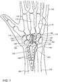
Fig. 1 schematically illustrates a dorsal view of a hand with a radiocarpal joint (RCJ) replacement, in accordance with some embodiments of the present invention; -
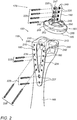
Fig. 2 schematically illustrates an exploded view of a radiocarpal joint (RCJ) replacement, in accordance with some embodiments of the present invention; -
Fig. 3A schematically illustrates a first side view of a radial member; -
Fig. 3B schematically illustrates a bottom view of a radial member; -
Fig. 3C schematically illustrates a second side view of a radial member; -
Fig. 3D schematically illustrates a top view of a radial member; -
Fig. 3E schematically illustrates a first perspective view of a radial member; -
Fig. 3F schematically illustrates a second perspective view of radial member; -
Fig. 4A schematically illustrates a side view of a carpal capitate bone insert, in accordance with some embodiments of the present invention; -
Fig. 4B schematically illustrates a side view of a bulbous component, in accordance with some embodiments of the present invention; -
Fig. 4C schematically illustrates a perspective view of a carpal capitate bone insert, in accordance with some embodiments of the present invention; -
Fig. 4D schematically illustrates a top view of a carpal capitate bone insert and a bulbous component, in accordance with some embodiments of the present invention; -
Fig. 5 schematically illustrates a dorsal view of a hand with a radiocarpal joint (RCJ) replacement, in accordance with some embodiments of the present invention; -
Fig. 6 schematically illustrates an exploded view of a radiocarpal joint (RCJ) replacement, in accordance with some embodiments of the present invention; -
Fig. 7 schematically illustrates a dorsal view of a hand with a radiocarpal joint (RCJ) cartilage replacement; -
Fig. 8 schematically illustrates an exploded view of a radiocarpal joint (RCJ) cartilage replacement; -
Fig. 9A schematically illustrates a bottom view of a cartilage replacement; -
Fig. 9B schematically illustrates a top view of a cartilage replacement; -
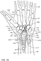
Fig. 10 illustrates a dorsal view of a hand with a distal radioulnar joint (DRUJ) replacement; -
Fig. 11 schematically illustrates a dorsal view of a hand with a distal radioulnar joint (DRUJ) replacement, showing the direction of applying screws in fixing the DRUJ in position; -
Fig. 12 schematically illustrates an exploded view of a distal radioulnar joint (DRUJ) replacement; -
Fig. 13A schematically illustrates a side view of a sigmoidal member with a hook; -
Fig. 13B schematically illustrates a top view of a sigmoidal member with a hook; -
Fig. 13C schematically illustrates a bottom view of a sigmoidal member with a hook; -
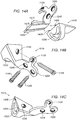
Fig. 14A schematically illustrates an exploded view of an ulnar member with a bore; -
Fig. 14B schematically illustrates a first perspective view of an ulnar member with a bore; -
Fig. 14C schematically illustrates a second perspective view of an ulnar member with a bore; -
Fig. 15 schematically illustrates a dorsal view of a hand with a combination of a radiocarpal joint (RCJ) replacement and a distal radioulnar joint (DRUJ) replacement, in accordance with some embodiments of the present invention; -
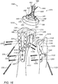
Fig. 16 schematically illustrates an exploded view of a combination of a radiocarpal joint (RCJ) replacement and a distal radioulnar joint (DRUJ) replacement, in accordance with some embodiments of the present invention; -
Fig. 17A schematically illustrates a first side view of a modified radial member; -
Fig. 17B schematically illustrates a bottom view of a modified radial member with a hook; -
Fig. 17C schematically illustrates a second side view of a modified radial member with a hook; -
Fig. 17D schematically illustrates a top view of a modified radial member with a hook; -
Fig. 17E schematically illustrates a first perspective view of a modified radial member with a hook; -
Fig. 17F schematically illustrates a second perspective view of a modified radial member with a hook; -
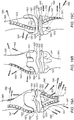
Fig. 18A schematically illustrates a dorsal view of hand bones; -
Fig. 18B schematically illustrates a side view of a proximal interphalangeal joint (PIP) replacement; -
Fig. 18C schematically illustrates a dorsal view of a proximal interphalangeal joint (PIP) replacement; -
Fig. 18D schematically illustrates a palmar view of a proximal interphalangeal joint (PIP) replacement; -
Fig. 19A schematically illustrates an anterior view of a tibiofemoral (TF) joint replacement; -
Fig. 19B schematically illustrates a posterior view of a tibiofemoral (TF) joint replacement; and -
Fig. 19C schematically illustrates a side view of a tibiofemoral (TF) joint replacement. - In the following detailed description, numerous specific details are set forth in order to provide a thorough understanding of the invention. However, it will be understood by those of ordinary skill in the art that the invention may be practiced without these specific details. In other instances, well-known methods, procedures, components, modules, units and/or circuits have not been described in detail so as not to obscure the invention.
- Although embodiments of the invention are not limited in this regard, discussions utilizing terms such as, for example, "processing," "computing," "calculating," "determining," "establishing", "analyzing", "checking", or the like, may refer to operation(s) and/or process(es) of a computer, a computing platform, a computing system, or other electronic computing device, that manipulates and/or transforms data represented as physical (e.g., electronic) quantities within the computer's registers and/or memories into other data similarly represented as physical quantities within the computer's registers and/or memories or other information non-transitory storage medium (e.g., a memory) that may store instructions to perform operations and/or processes. Although embodiments of the invention are not limited in this regard, the terms "plurality" and "a plurality" as used herein may include, for example, "multiple" or "two or more". The terms "plurality" or "a plurality" may be used throughout the specification to describe two or more components, devices, elements, units, parameters, or the like. Unless explicitly stated, the method described herein are not constrained to a particular order or sequence. Additionally, some of the described methods or elements thereof can occur or be performed simultaneously, at the same point in time, or concurrently. Unless otherwise indicated, us of the conjunction "or" as used herein is to be understood as inclusive (any or all of the stated options).
- Previously, different wrist implant topologies involved the resection of portions of the radius and/or ulna bones and affixing portions of the implant components, such as pegs, within the soft intramedullary canal. Such soft tissue stabilizing techniques of the implant components in the soft medullary tissue have been shown to loosen over time and ultimately fail, which requires additional surgery to fix and re-stabilize the implants. Moreover, in some implant topologies, the implant components may be bolted across multiple carpal bones to fix the multiple carpal bones in place severely limiting wrist movements. Some implants may bond portions of the radius to the ulna particularly in the case after large resections of those bones. These implant topologies severely limit the motion in the multiple wrist joints and may cause early loosening of the implant.
- Described herein are a method and apparatus for wrist arthroplasty including radiocarpal joint (RCJ) and distal radioulnar joint (DRUJ) replacements. A method and apparatus for renewing the articular surface of the distal radius with a cartilage replacement can be used to repair damage, for example, from intra-articular fractures of the distal radius (e.g., from sport injuries) according to some embodiments of the present invention is also taught herein without the need to replace the entire joint (e.g., hemi-arthroplasty). Implant solutions according to some embodiments of the present invention overcome many of the implant failure and joint mobility problems seen in previous wrist implants and prostheses.
- Wrist implants according to some embodiments of the present invention further account for minimal bone resection, preservation of the mobility of the radiocarpal, intercarpal and carpometacarpal joints, and a reduction of shear, bending and frictional forces in the implant components so as to prevent a loosening of the implant. Wrist implant topologies according to some embodiments of the present invention do not apply a classic ball and socket approach to the joint, but apply methods of joint articular surface reconstruction to the complex joint surfaces. Implant technologies according to some embodiments of the present invention include wrist implant topologies which combine radiocarpal joint (RCJ) replacement with the option of DRUJ resurfacing replacement and stabilization within the same implant.
- Implant topologies according to some embodiments of the present invention utilize a plate fixation method whereby the implant components are plate-like and use screws to affix the plate components to the hard outer cortical bone layers for better implant stability. There is minimal bone resection with minimal placement of the implant components within the soft issue of the medullary cavity to stabilize the implant. Plate-like components used in some embodiments of the present invention employ a closed frame construction, such as the Y-plate affixed to the radius used in the RCJ implant as will described later, so as to achieve maximum contact and mechanical stability of the implant with prevention of implant failure. Surgical techniques employed for implanting the wrist replacements are simple and easy.
-
Fig. 1 schematically illustrates a dorsal view of ahand 105 with a first embodiment of a radiocarpal joint (RCJ)replacement 100, in accordance with some embodiments of the present invention.Hand 105 includesmetacarpal bones 110, and the carpal bones, or carpus, includingcarpal trapezoid bone 115,carpal trapezium bone 120,carpal capitate bone 125,carpal hamate bone 130, and carpals triquetral/pisiform bones 135. - To implant the RCJ replacement shown in
Fig. 1 in the wrist ofhand 105, the carpal lunate bone is removed from aregion 140 fromhand 105. Acarpal scaphoid bone 145 is surgically cut along acut plane 150 and cartilage is removed from the RCJ.Radius bone 165 andulna bone 170 are shown inFig. 1 . - A
radial member 155 of the RCJ replacement includesholes 160 through which fasteners, typically screws, are to be inserted and threaded to allow affixing, attaching, or lockingradial member 155 to a portion of an end ofradius bone 165 proximal to the wrist. In contrast to the problems associated with soft tissue mounting of implants,radial member 155 is typically affixed to the cortex of radius bone 165 (e.g., cortical bone tissue of the radius bone) so as to provide a solid mechanical support for the RCJ replacement. - A
carpal capitate member 175 includes a carpalcapitate bone insert 180 and abulbous component 183.Carpal bone insert 180 of the RCJ replacement is configured to be inserted and affixed only tocarpal capitate bone 125 of the wrist, but not to other carpal bones, allowing greater maneuverability of the wrist, as a result. Carpalcapitate bone insert 180 is coupled tobulbous component 183, which includes aconvex head 185 substantially opposite to carpalcapitate bone insert 180. -
Fig. 2 schematically illustrates an exploded view of radiocarpal joint (RCJ)replacement 100, in accordance with some embodiments of the present invention.Radial member 155 of the radiocarpal joint (RCJ) replacement includes aradial fixture 210 to be affixed over a longitudinal aspect of the radial bone.Radial fixture 210 may have various forms, designed to match and provide good anchorage and coupling with the radius bone when attached to it. For example,radial fixture 210 may be V-shaped designed to present two joined bars that are to be affixed laterally ontoradial bone 165. -
Radial member 155 further includes a radialarticular resurfacing plate 213 having a substantially smooth concave surface that is to be located at the end of the radial bone proximal to the wrist for supporting theradial member 155 when in-situ. The wrist includes the carpal bones and multiple joints that intercommunicate in a common synovial cavity. "Proximal" to the wrist refers, in the context of the present application, to the side ofradial bone 165 nearest the carpal bones. This portion of the radial bone is referred to, in the context of the present application, as the distal radius. Radialarticular resurfacing plate 213 is attached substantially perpendicular to V-shapedradial fixture 210 as shown inFig. 2 . - Carpal
capitate bone insert 180 includes a dorsal surfacecortical plate 247 and acentral intraosseous stem 249. Abulbous component 183 is configured to be flexibly coupled to carpalcapitate bone insert 180 and located substantially opposite to carpalcapitate bone insert 180.Bulbous component 183 includes aconvex head 185 having a convex surface (e.g., the articular resurfacing plate of carpal capitate member 175). - Dorsal surface
cortical plate 247 is a fixture of carpalcapitate member 175 which is externally affixed to the cortical bone tissue of carpalcapitate bone 125. Dorsalcortical plate 247 is maneuvered, during the implantation procedure, to be positioned on the dorsal cortical position of carpalcapitate bone 125 and stem 249 is inserted into the central intraosseous position of the carpal capitate bone. Four screw holes 220 for fourscrews 225 are located on both stem 249 andplate 247 ofinsert 180. Fourscrews 225 traversecarpal capitate bone 125 in the dorsal to palmar direction so as to affixplate 247 tocarpal capitate bone 125 and centralintraosseous stem 249; however, any number screws may be used. - The head of
stem 249 includes several petals, in this example, four petals. Twopetals 245 are generally oriented in the dorsal-volar direction and twopetals 250 are generally oriented in the radioulnar direction. The petals are flexibly configured to snap-in, or connect to aneck 253, so as to holdbulbous component 183 to carpalcapitate bone insert 180. - Radial
articular resurfacing plate 213 ofradial member 155 with the concave surface is configured to be operably coupled to the convex surface ofconvex head 185 ofbulbous component 183 of carpalcapitate member 175 so as to allow radial freedom of motion ofbulbous component 183 of carpalcapitate member 175 with respect to radialarticular resurfacing plate 213 after implantation. Note that the term "operably coupled" in the context of wrist arthroplasty is defined herein to mean that in coupling, bonding, connecting or otherwise holding together the two components forming the wrist joint replacement, implant, or prostheses, with two articulating surfaces, the motion of the two articulating surfaces are identical, or most closely replicate, the same motions found in equivalent in vivo joint articulating surfaces (e.g., anatomical movements of the RCJ articulation). Stated differently by way of example, the movements, or motions, of the RCJ replacement after implantation would most closely replicate the same movements, or motions, found equivalently in a normal (healthy) radiocarpal joint in the wrist. - Radial fixture 210 (the dorsal plate), includes
holes 160 through which fasteners, typically screws 225, are used for plate fixation ofradial member 155 to the radial bone cortex. This technique for assembling the RCJ replacement is referred to, in the context of the present application, as dorsal radius fracture fixation. In some embodiments, holes 160 have threading forscrews 225 to be fixed toradial member 155. One ormore holes 227 on the central region of the "V" pass are oval shaped. Screwingscrew 225 into a chosen side ofoval hole 227 applies a longitudinal stress tofixture 210 in the direction of the chosen side so as to allow an additional degree of freedom for placing and fasteningradial fixture 210 to radius bone 215. Although a V-shaped radial fixture is described, aimed at providing good mechanical stability, other shapes may be considered, too. The V-shape is not in any way limiting the embodiments of the present invention to that shape. Other shapes for the radial fixture may be used with varying number of screws and respective screw holes in any geometric orientation. - Radial fixture 210 (dorsal plate) is also connected to radial
articular resurfacing plate 213. Twotriangular pegs 230 that are formed in the bottom side of radialarticular resurfacing plate 213 are designed to be pressed against and penetrate into the end of the radius bone as shown inFig. 2 , for enhanced stability.Triangular pegs 230 also includeholes 240.Screws 235 may be screwed through obliquely threaded screw holes 234 formed in radial fixture 210 (e.g., dorsal plate). Screw holes 234 are not on the same lateral position along both side offixture 210 so as to compensate for the shapes ofradial bone 165 and the end of radial bone 165 (e.g., the radial articular surface).Screws 235 pass throughradius bone 165 to threaded screw holes 235 and 240 at an oblique angle of about 43 degrees with the bottom surface of radialarticular resurfacing plate 213opposite radius bone 165. Fastening screws 235 are used for affixingradial member 155 viapegs 230 of the radiocarpal joint (RCJ) replacement toradial bone 165, which forms a mechanically stable pyramid-like closed frame, enhancing self-support. -
Fig. 3A schematically illustrates a first side view ofradial member 155. -
Fig. 3B schematically illustrates a bottom view ofradial member 155. -
Fig. 3C schematically illustrates a second side view ofradial member 155, -
Fig. 3D schematically illustrates a top view ofradial member 155. -
Fig. 3E schematically illustrates a first perspective view ofradial member 155,. -
Fig. 3F schematically illustrates a second perspective view ofradial member 155, -
Radial member 155 of the radiocarpal joint (RCJ) replacement includes aradial fixture 210 which is integrally formed with radialarticular resurfacing plate 213. Radialarticular resurfacing plate 213 is concave 312 toward the carpus, or carpal bones, andconvex surface 314 toward the radial articular surface of the radial bone according to the normal anatomical concavity of the articular surface of the distal radius. In some embodiments, radialarticular resurfacing plate 213 withconcave surface 312 is fabricated or formed to present a highly polished metal surface.Convex surface 314 may be coated (e.g., hydroxylapatite) for better contact with the distal radius bone and also to allow for bone growth. -
Radial fixture 210 also includesholes 160 for screws to affix theradial member 155 to the cortex of the radius and anoval hole 227 which allows another longitudinal degree of freedom in firmly attachingradial fixture 210 to the radius bone as described inFig. 2 . The volar ridge of plate 213 (e.g., side ofplate 213 proximal to the palm of the subject's hand) includes avolar hook 335.Volar hook 335 increases the stability of radial articular resurfacing plate 310 mounted on to the end of the radius bone proximal to the wrist. - Two
triangular pegs 230 are formed inconvex surface 314 of radial articular resurfacing plate 213 (e.g., on the volar portion of plate 213).Pegs 230 havescrew holes 240 such that twolock screws 235 mounted throughholes 240 and holes 234 (as described inFig. 2 ) formed inradial fixture 210 prevent a rotation of radialarticular resurfacing plate 213. Radialarticular resurfacing plate 213 has adeltoid notch 340 so as to accommodate Lister's tubercle and the bone joint capsule. -
Fig. 4A schematically illustrates a side view of carpalcapitate bone insert 180, in accordance with some embodiments of the present invention. When implanting carpalcapitate bone insert 180,central intraosseous stem 249 is inserted and implanted into the central intraosseous position of the carpal capitate bone. Dorsalcortical plate 247 is maneuvered, during the implantation procedure, to be positioned on the dorsal cortical position of carpalcapitate bone 125. - Four screw holes 220 for four
screws 225 are located on both stem 249 andplate 247 ofinsert 180. Fourscrews 225 traverse and are threaded through carpalcapitate bone 125 in the dorsal to palmar direction so as to affixplate 247 tocarpal capitate bone 125 and centralintraosseous stem 249; however, any number screws may be used.Holes 220 inplate 247 are parallel toholes 220 instem 249.Plate 247 is connected to stem 249 at aproximal end 418 ofstem 249. Also connected to aproximal end 418 ofstem 249 are four petals. Twopetals 245 are oriented in the dorsal-volar direction and twopetals 250 are oriented in the radioulnar direction. - In some embodiments, carpal
capitate bone insert 180 may be formed from titanium or stainless steel. In other embodiments, stem 249 are prepared with plasma deposited hydroxylapatite which gives stem 249 a corrugated coated surface for better bone growth and adhesion whenstem 249 is implanted within the central intraosseous position of the carpal capitate bone. -
Fig. 4B schematically illustrates a side view ofbulbous component 183, in accordance with some embodiments of the present invention.Bulbous component 183 includes a firstconvex head 440 and (second) convex head 185 (as described previously inFigs. 1-2 ), substantially opposite each other and connected byneck 253 defining anannular groove 430 between firstconvex head 440 and secondconvex head 185. -
Fig. 4C schematically illustrates a perspective view of carpalcapitate bone insert 180, in accordance with some embodiments of the present invention. -
Fig. 4D schematically illustrates a top view of carpalcapitate bone insert 180 andbulbous component 183, in accordance with some embodiments of the present invention. The four petals are substantially flexible and are configured to snap intoannular ring 430 ofneck 253 ofbulbous component 183. Thus, the petals squeeze, hold, or bite onneck 253 of the bulbous component under pressure, which affixes carpalcapitate bone insert 180 tobulbous component 183. However since the petals are flexible, small deviations in motion up to 4 mm in any direction between centralintraosseous stem 249 and firstconvex head 440 ofbulbous component 183 may occur. Thus, in this context of the present application, the carpalcapitate bone insert 180 is configured to be flexibly coupled to firstconvex head 440 of the bulbous component. A carpal capitate member may be defined herein as to include carpalcapitate bone insert 180 flexibly coupled tobulbous component 183. - According to some embodiments of the invention, there may be provided bulbous components with different neck sizes to cater for various palm sizes.
Bulbous component 183 may be made from a material selected from the group consisting of polyethylene, pyrocarbon, and ceramic. Similarly, the bulbous components may be provided with secondconvex heads 185 of different sizes. However, the size of secondconvex heads 185 is typically the same or similar for most purposes. The size of the carpal capitate member and can be predetermined by snapping in a bulbous component, for example, having the proper neck size to suit the patient's palm size. The adjustment of the size of the carpal capitate member in this manner can be used to balance between the tension and wrist motion during implantation so as optimize performance of the RCJ replacement. - The RCJ replacement effectively has two joints that can move during the motion of the RCJ wrist replacement. Movement in the first joint in the RCJ replacement mainly occurs where the convex surface of second
convex head 185 is configured to be operably coupled to radialarticular resurfacing plate 213. The area of the convex head articulates with the radial articular resurfacing plate of substantially the same area. In addition, the flexible coupling between carpalcapitate bone insert 180 andbulbous component 183 forms a second flexible joint with another degree of freedom in the movement of the overall RCJ replacement. The flexible movements possible in the second joint are small relative to the large radial movements in the first joint. -
Fig. 5 schematically illustrates a dorsal view ofhand 105 with radiocarpal joint (RCJ)replacement 500, in accordance with some embodiments of the present invention.Dorsal view 500 ofhand 105 includesmetacarpal bones 110, and the carpal bones, or carpus, includingcarpal trapezoid bone 115,carpal trapezium bone 120,carpal capitate bone 125,carpal hamate bone 130, and carpals triquetral/pisiform bones 135. - To implant the RCJ replacement in the second embodiment of
Fig. 5 in the wrist ofhand 105, the carpal lunate bone is removed from aregion 140 fromhand 105. Acarpal scaphoid bone 145 is surgically cut along acut plane 150 and cartilage is removed from the RCJ.Radius bone 165 andulna bone 170 are shown inFig. 5 . - A
radial member 155 of the RCJ replacement includes radial member holes 160 through which fasteners, typically screws can be inserted and threaded to allow affixing or lockingradial member 155 to a portion of an end ofradius bone 165 proximal to the wrist. In contrast to soft tissue mounting of implants,radial member 155 is typically affixed to the cortex ofradius bone 165 to provide a solid mechanical support for the RCJ replacement. - A
carpal capitate member 575 includes a carpalcapitate insert screw 580 andbulbous head 183. Carpalcapitate member 575 of the RCJ replacement is configured to be affixed byscrew 580 only tocarpal capitate bone 125 of the wrist, but not to other carpal bones, allowing greater maneuverability of the wrist, as a result.Screw 580 may also be referred to as a carpal capitate member fixture of carpalcapitate member 575 held externally affixed by the cortical bone tissue and enters the cancellous bone tissue inside. The head ofscrew 580 includes a spherical highly polished small head. In the same manner, as described inFig. 4 , carpalcapitate insert screw 580 is flexibly coupled tobulbous component 183 withconvex head 185. -
Fig. 6 schematically illustrates an exploded view 600 of a radiocarpal joint (RCJ) replacement, in accordance with some embodiments of the present invention. Aradial member 155 of the radiocarpal joint (RCJ) replacement includes aradial fixture 210 in the shape of a "V" which affixed the radial member laterally ontoradial bone 165 and radialarticular resurfacing plate 213 having a substantially smooth concave surface located at the end of the radial bone proximal to the wrist. Radialarticular resurfacing plate 213 is attached at a nearly 90 degree angle to V-shapedradial fixture 210 as shown inFig. 6 . - Carpal
capitate member 575 includesscrew 580 with wide threads along the shank which is inserted, threaded, implanted, or affixed to the carpal capitate bone. The head ofscrew 580 includes four petals. Twopetals 245 are oriented in the dorsal-volar direction and twopetals 250 are oriented in the radioulnar direction. The petals are configured to be connected to aneck 253 ofbulbous component 183. Twopetals 250 oriented in the radioulnar direction each have threaded oblique holes 647. - After implantation of the screw into the carpal capitate bone, two locking screws are threaded through the carpal capitate bone, through
channels 648 formed in the shank of maincapitate screw 580 and into oblique holes 647. Afirst locking screw 649 is mounted from threadedoblique hole 647 and is oriented toward the ulnar dorsal base of the carpal capitate bone. Asecond locking screw 651 is mounted from threadedoblique hole 647 and is oriented toward the radial volar base of the carpal capitate bone. The shank ofscrew 580 is coated for good contact and good bone growth with plasma deposited hydroxylapatite for implantation within the central intraosseous position of the carpal capitate bone. - Stated differently, in some embodiments, carpal capitate insert includes an implant insertion element selected from the group consisting of
stem 249 andscrew 580. The implant insertion element is implanted into the central intraosseous position of the carpal capitate bone and may be coated with hydroxylapatite. -
Bulbous component 183 includes aconvex head 185 having a convex surface. The fourpetals bulbous component 183 such that the four petals squeeze and bite down onannular ring 430 ofneck 253 as described inFig. 4 so as to affix the bulbous component to the carpal capitate bone insert. Applying bulbous components with different neck sizes, for example, allow for adjusting the size of carpal capitate member (e.g.,bone insert 575 and bulbous component 183) as described for the embodiment shown inFig. 4 so as to balance between the tension and wrist motion during implantation. - Radial
articular resurfacing plate 213 ofradial member 155 with the concave surface is configured to be operably coupled to the convex surface ofconvex head 185 ofbulbous component 183 of carpalcapitate member 575 so as to allow radial freedom of motion ofbulbous component 183 of carpalcapitate member 575 with respect to radialarticular resurfacing plate 213 after implantation. The area of the convex surface ofconvex head 185 is substantially the same as the area of radialarticular resurfacing plate 213. -
Radial fixture 210, or dorsal plate, includesholes 160 through which fasteners, typically screws 225, are used for plate fixation ofradial member 155 to the radial bone cortex. This technique for assembling the RCJ replacement may also be referred to as dorsal radius fracture fixation. In some embodiments, holes 160 have threading forscrews 225 to be fixed toradial member 155. Two or threeholes 227 on the central region of the "V" are oval which allow compression ofradial fixture 210 longitudinally toradius bone 165. - Radial fixture 210 (dorsal plate) is also connected to radial
articular resurfacing plate 213. Twotriangular pegs 230 that are formed in the bottom side of radialarticular resurfacing plate 213 are designed to be pressed against and penetrate into the end of the radius bone as shown inFig. 2 , for enhanced stability.Triangular pegs 230 also includeholes 240.Screws 235 may be screwed through obliquely threaded screw holes 234 formed in radial fixture 210 (e.g., dorsal plate). Screw holes 234 are not on the same position alongfixture 210 so as to compensate for the shapes ofradial bone 165 and the end of radial bone 165 (e.g., the radial articular surface).Screws 235 pass throughradius bone 165 to threaded screw holes 240 at an oblique angle of about 43 degrees with the bottom surface of radialarticular resurfacing plate 213opposite radius bone 165. Fastening screws 235 are used for affixingradial member 155 viapegs 230 of the radiocarpal joint (RCJ) replacement toradial bone 165, which forms a mechanically stable pyramid-like closed frame, enhancing self-support. -
Fig. 7 schematically illustrates a dorsal view ofhand 105 with a radiocarpal joint (RCJ)cartilage replacement 700. The wrist bones shown inFig. 7 are identical to that ofFig. 1 with the exception thatcarpal scaphoid bone 145 is not surgically cut and the carpallunate bone 705 is not removed as described previously for the RCJ joint replacement. Here, all of the carpal bones are present. In the event of a sports injury where cartilage in the RCJ joint is fractured or damaged, the damaged cartilage is removed. However, aplastic cartilage replacement 710 is inserted and attached toradial member 155. The carpal bones are operably coupled tocartilage replacement 710 on a first side proximal to the wrist (e.g., to the carpal bones) so as to restore normal wrist motion after the RCJ cartilage was removed. The second side ofcartilage replacement 710 is affixed toradial member 155. -
Fig. 8 schematically illustrates an exploded view of radiocarpal joint (RCJ)cartilage replacement 700.Radial member 155 is affixed to a portion of an end ofradial bone 165 proximal to the wrist (e.g., the carpal bones of the wrist) by the same procedures described in the embodiments shown inFigs. 1-6 . However,radial member 155 also includes tab holes 805 and 807 which are configured to receivetabs side 830 ofcartilage replacement 710 proximal toradial member 155. In this manner,second side 830 ofcartilage replacement 710 is affixed toradial member 155. Along afirst side 820 ofcartilage replacement 710, the carpal bones are operably coupled to ofcartilage replacement 710, such that the wrist withcartilage replacement 710 can substantially exhibit the same motions as a normal (healthy) wrist. -
Fig. 9A schematically illustrates a bottom view ofcartilage replacement 710. The bottom view ofcartilage replacement 710 showstabs -
Fig. 9B schematically illustrates a top view ofcartilage replacement 710. The top view ofcartilage replacement 710 shows concave surface 820 (e.g., the first surface). In some embodiments, the plastic ofconcave surface 820 is machined and polished with optimal concavity to be operably coupled to the carpal bones in the wrist, such as for example, optimized to articulate withcarpal scaphoid 145 and carpal lunate 705 (seeFig. 7 ). - When pathologies exist in the distal radioulnar joint (DRUJ), such as sigmoid notch damage, that affect supination and pronation movements of the wrist, a DRUJ replacement can be implanted to alleviate the dysfunction.
-
Fig. 10 illustrates a first dorsal view ofhand 105 with a distal radioulnar joint (DRUJ)replacement 1000. Asigmoidal member 1005 is affixed to anulnar side 1010 ofradius bone 165 proximal to the wrist, or the bones in the wrist. Anulnar member 1015 is affixed to aradial side 1020 ofulna bone 170 and proximal to the wrist bones.Sigmoidal member 1005 also includes ahook 1040 which is inserted and held inulnar member 1015 such thatsigmoidal member 1005 is configured to be operably coupled toulnar member 1015 so as to facilitate supination and pronation movement of the wrist and provide DRUJ stability. -
Fig. 11 schematically illustrates a second dorsal view ofhand 105 with distal radioulnar joint (DRUJ)replacement 1000.Sigmoidal member 1005 includes atriangular peg 1105 that includes a threaded hole (not shown).Triangular peg 1105 is impacted, implanted, pressed, or hammered into the cancellous bone of the distal radius.Sigmoidal member 1005 is affixed to the distal radius by ascrew 1120 that is inserted into ascrew hole 1110 and is threaded into a screw hole (not shown) intriangular peg 1105. Similarly, alower mounting bracket 1117 ofsigmoidal member 1005 is affixed toradius bone 165 alongulnar side 1010 by ascrew 1135 which is threaded into ascrew hole 1115. Lower mountingbracket 1117 is affixed over a longitudinal aspect of the radial bone. This closed frame construction provides stability and dissipates forces acrosssigmoidal member 1005, which is similar to the topology for affixingradial member 155. -
Ulnar member 1015 is also constructed with atriangular block 1133 that restores a partial oblique resection of the articular surface of anulnar head 1140 ofulna bone 170, restoring nearly 2/3 of the ulnar head.Ulnar member 1015 is partially affixed by ascrew 1125 inserted to threaded throughscrew hole 1130 intotriangular block 1133. -
Fig. 12 schematically illustrates an exploded view of distal radioulnar joint (DRUJ)replacement 1000.Sigmoidal member 1005 includeshook 1040. After impactingpeg 1105 into the distal radius bone as described previously,sigmoidal member 1005 is affixed to theradius bone 165 by three screws.Screw 1120 is threaded obliquely throughhole 1110 through the radial head into a threadedhole 1205 inpeg 1105. Lower mountingbracket 1117 ofsigmoidal member 1005 is affixed toradius bone 165 alongulnar side 1010 byscrew 1135 threaded intoscrew hole 1115, and ascrew 1220 threaded into ascrew hole 1210. - A
bore 1230 is formed intoulnar portion 1015.Bore 1230 may also be referred to herein as a supination-pronation tunnel. In some embodiments, bore 1230 may include a track formed inulnar portion 1015. In other embodiments, bore 1230 may include a groove formed inulnar portion 1015.Ulnar portion 1015 is held toulna bone 170 by three screws as shown inFig. 12 .Screw 1125 is inserted obliquely into threadedhole 1130 crosses the resected portion of the ulna head and is threaded into ahole 1235 intriangular block 1133. The lower portion of the ulnar member is affixed toulna bone 170 by twoscrews screw holes -
Hook 1040 ofsigmoidal member 1005 is inserted and held inbore 1230 inulnar member 1015 which is configured to receivehook 1040, and retain the hook after implantation. Althoughbore 1230 is shaped like a "C", the C-shape has been determined to provide good stability of the DRUJ replacement when the wrist is moved in pronation and supination, any suitable bore shape can be chosen so as to optimize the joint stability and performance. -
Fig. 13A schematically illustrates a side view ofsigmoidal member 1005 withhook 1040. -
Fig. 13B schematically illustrates a top view ofsigmoidal member 1005 withhook 1040. -
Fig. 13C schematically illustrates a bottom view ofsigmoidal member 1005 withhook 1040. -
Peg 1105 is impacted into the cancellous bone of the distal radius and affix toradius 165 byscrew 1120 threaded throughholes Figs. 10-12 .Sigmoidal member 1005 may be formed from polished stainless steel or titanium. -
Fig. 14A schematically illustrates an exploded view ofulnar member 1015 withbore 1230. -
Fig. 14B schematically illustrates a first perspective view ofulnar member 1015 withbore 1230. -
Fig. 14C schematically illustrates a second perspective view ofulnar member 1015 withbore 1230, - As shown in
Fig. 14A ,ulnar member 1015 may be formed from two separate pieces: areceptacle piece 1410 and a mountingpiece 1420.Receptacle piece 1410 includes with tworails 1405.Bore 1230 is formed inreceptable piece 1410 and configured to receivehook 1040. Mountingpiece 1420 includes the screw holes used for affixing the ulnar member to the ulna bone and also includestracks 1415 into which rails 1405 can be slid so as to holdreceptacle piece 1410 on mountingpiece 1420. In this manner,receptacle piece 1410 may be adjusted to have different overall lengths.Receptacle piece 1410 with different sizes or shapes ofbore 1230 may also be used to optimize the performance of the DRUJ replacement. The screws and screw holes are the same as described inFigs. 10-12 .Receptacle piece 1410 is formed from a material selected from the group consisting of mobile polyethylene and pyrocarbon. Mountingpiece 1420 is formed from a material selected from the group consisting of stainless steel and titanium. In some embodiments, the stainless steel and titanium may be impregnated with hydroxylapatite. -
Fig. 15 schematically illustrates a dorsal view ofhand 105 with acombination 1500 of a radiocarpal joint (RCJ) replacement and a distal radioulnar joint (DRUJ) replacement, in accordance with some embodiments of the present invention. In the event that the subject, or patient, requires both a RCJ and DRUJ replacement, the embodiments shown inFigs. 5 and10 may be combined as shown inFig. 15 . The description as to how the various members are affixed to the carpal capitate, radial and ulna bones is as described previously. However,radial member 155 is modified to include the elements of the sigmoidal member, namelyhook 1040 andlower mounting bracket 1117 ofsigmoidal member 1005. -
Fig. 16 schematically illustrates an exploded view ofcombination 1500 of a radiocarpal joint (RCJ) replacement and a distal radioulnar joint (DRUJ) replacement, in accordance with some embodiments of the present invention. A modifiedradial member 1510 withhook 1040 andlower mounting bracket 1117 ofsigmoidal member 1005 is affixed toradial bone 165.Ulnar member 1015 is affixed toulna bone 170. - After implantation,
radial resurfacing plate 213 of modifiedradial member 1510 with the concave surface is configured to be operably coupled to the convex surface ofconvex head 185 of carpalcapitate member 575 so as to allow radial freedom of motion of the carpal capitate member with respect to the radial resurfacing plate of the RCJ replacement.Hook 1040 is inserted intobore 1230, which is configured to receive and retain the hook. The bore in the DRUJ replacement is shaped to allow relative movements between the radial bone and ulna bone so as to facilitate supination and pronation movement of the wrist. Note that either embodiment of carpal capitate member may be used in the RCJ replacement inFigs. 15-16 (e.g.,carpal capitate member 175 or carpal capitate member 575). -
Fig. 17A schematically illustrates a first side view of modifiedradial member 1510 -
Fig. 17B schematically illustrates a bottom view of modifiedradial member 1510 withhook 1040. -
Fig. 17C schematically illustrates a second side view of modifiedradial member 1510 withhook 1040. -
Fig. 17D schematically illustrates a top view of modifiedradial member 1510 withhook 1040. -
Fig. 17E schematically illustrates a first perspective view of modifiedradial member 1510 withhook 1040. -
Fig. 17F schematically illustrates a second perspective view of a modified radial member withhook 1040. - Modified
radial member 1510 is identical toradial member 155 as shown inFig. 3 , with the exception that hook 1040 andlower mounting bracket 1117 fromsigmoidal member 1105 are integrally formed in modifiedradial member 1510. - The wrist implants shown above may use implant fixtures affixed externally to the cortical bone tissue of the wrist bones (e.g., carpal capitate, radius, and ulna bones) so as to provide implant stability. Articular surfaces may be formed and/or attached to each of the implant fixtures such that when assembled, the movements of the joint articulating surfaces after implant assembly may closely resemble the anatomical movement of healthy joints. Moreover, pegs may be attached to the bottom side of the articulating surfaces (e.g., on the side of the articulating surfaces opposite the joint). The pegs may be pressed and implanted into the bone, for example into cancellous bone tissue, at the end of the bone for better self-enhancing implant stability. Screws passing through screw holes in the implant fixtures passing through the cortical bone tissue, for example, and into holes in the pegs may provide even greater stability so as to anchor the implant, for example, with a pyramid-like closed frame. The closed external frame joint resurfacing system fixation methods shown above for the radiocarpal and distal radioulnar joint replacement apparatus for implantation in a wrist of a subject and may thus be extended to other joint implants in the body.
-
Fig. 18A schematically illustrates a dorsal view ofhand bones 1800. -
Hand bones 1800 of a human hand may includedistal phalanges 1802,middle phalanges 1804,proximal phalanges 1806,metacarpals 1808, andcarpals 1809. Joints between the finger bones may include a distal interphalangeal joint 1803 (DIP), a proximal interphalangeal joint 1805 (PIP), and a metacarpophalangeal joint 1807. Below is a description of embodiments of a joint replacement for implantation into PIP joint 1805 as shown in acircle 1807 ofFig. 18A . -
Fig. 18B schematically illustrates a side view of a proximal interphalangeal joint (PIP)replacement 1810. -
Fig. 18C schematically illustrates a dorsal view of proximal interphalangeal joint (PIP)replacement 1810. -
Fig. 18D schematically illustrates a volar view of proximal interphalangeal joint (PIP)replacement 1810. -
PIP replacement 1810 may include a middle phalange (MP)member 1825 attached tomiddle phalange 1804, and a proximal phalange (PP)member 1835 attached toproximal phalange 1806.MP member 1825 may include an MP fixture 1823 (e.g., one or more MP fixtures) externally affixed to cortical bone tissue along a longitudinal aspect ofmiddle phalange 1804, and anMP resurfacing plate 1820 at the end ofmiddle phalange 1804 proximal to PIP joint 1805. "Proximal" in the embodiments ofFigs. 18 and19 refers, in the context of the present application, to the side of bone closest to the joint in which the joint replacement apparatus is implanted. For example, in the embodiments shown inFigs. 18A-18D , proximal to the PIP joint 1805.Screws 1840 screwed throughholes 1827 may be used to affixMP fixture 1823 externally to cortical bone tissue along a longitudinal aspect ofmiddle phalange 1804. -
PP member 1835 may include aPP fixture 1833 externally affixed to cortical bone tissue along a longitudinal aspect ofproximal phalange 1806, and aPP resurfacing plate 1830 at the end ofproximal phalange 1806 proximal to PIP joint 1805.Screws 1840 screwed throughholes 1837 may be used, for example, to affixPP fixture 1833 externally to cortical bone tissue along a longitudinal aspect ofproximal phalange 1806. - Attached to the side of
MP resurfacing plate 1820 opposite to PIP joint 1805 are one or more MP pegs 1821 (e.g., one peg shown inFigs. 18A-18D ) for insertion into cancellous bone tissue inmiddle phalange 1804.Screws 1842 may be used to affixMP resurfacing plate 1820 to the end ofmiddle phalange 1804 proximal to PIP joint 1805 by screwingscrews 1842 into one or moreMP peg holes 1822 in one or more MP pegs 1821. This provides additional implant stability. - Similarly, attached to the side of
PP resurfacing plate 1830 opposite to PIP joint 1805 are one or more PP pegs 1831 for insertion into cancellous bone tissue inproximal phalange 1806.Screws 1842 may be used to affixPP fixture 1833 to the end ofproximal phalange 1806 proximal to PIP joint 1805 by screwingscrews 1842 into one or morePP peg holes 1832 in one or more respective PP pegs 1831. - In some examples, after implantation each of
MP resurfacing plate 1820 andPP resurfacing plate 1830 are shaped, to fit and to move together, so as to facilitate anatomical movements of the proximal interphalangeal joint (PIP) articulation (e.g., PIP joint 1805). In the context of the present patent application, "anatomical movements" is defined herein to mean that in coupling, bonding, connecting or otherwise holding together the components forming the joint replacement, implant, or prostheses, with two articulating resurfacing plate surfaces, the motion of the two articulating surfaces are identical, or most closely replicate, the same motions found in equivalent in vivo joint articulating surfaces of the joint articulation. Stated differently, the movements, or motions, of the joint replacement after implantation would most closely replicate the same movements, or motions, found equivalently in a normal (healthy) joint. -
Fig. 19A schematically illustrates an anterior view of a tibiofemoral (TF)joint replacement 1900. -
Fig. 19B schematically illustrates a posterior view of tibiofemoral (TF)joint replacement 1900. -
Fig. 19C schematically illustrates a side view of tibiofemoral (TF)joint replacement 1900. - A tibiofemoral joint (TF) 1915 of the knee is the articulation between a
femur 1905 and atibia 1910 bones of the human leg as shown in the different views inFigs. 19A-19C . -
TF replacement 1900 may include afemur member 1925 attached tofemur 1905, and atibia member 1935 attached totibia 1910.Femur member 1925 may include a femur fixture 1923 (e.g., one or more femur members) externally affixed to cortical bone tissue along a longitudinal aspect offemur 1905, and afemur resurfacing plate 1920 at the end offemur 1905 proximal to TF joint 1915.Screws 1940 screwed throughholes 1927 may be used to affixfemur fixtures 1923, for example, externally affixed to cortical bone tissue along a longitudinal aspect offemur 1905. -
Tibia member 1935 may include atibia fixture 1933 externally affixed externally to cortical bone tissue along a longitudinal aspect oftibia 1910, and atibia resurfacing plate 1930 at the end oftibia 1910 proximal to TF joint 1915.Screws 1940 screwed throughholes 1937 may be used to affixtibia fixture 1933, for example, externally affixed to cortical bone tissue along a longitudinal aspect oftibia 1910. - Attached to the side of
femur resurfacing plate 1920 opposite to TF joint 1915 are one or more femur pegs 1921 for insertion into cancellous bone tissue infemur 1905.Screws 1942 may be used to affixfemur resurfacing plate 1920 to the end offemur 1905 proximal to TF joint 1915 by screwingscrews 1942 through one or morefemur peg holes 1922 through one or more respective femur pegs 1921. - Similarly, attached to the side of
tibia resurfacing plate 1930 opposite to TF joint 1915 are one or more tibia pegs 1931 for insertion into cancellous bone tissue intibia 1910.Screws 1942 may be used to affixtibia fixture 1933 to the end of tibia 1910proximal to TF joint 1915 by screwingscrews 1942 through one or moretibia peg holes 1932 through one or more respective tibia pegs 1931 so as to provide additional implant stability. - In some examples, after implantation each of
femur resurfacing plate 1920 andtibia resurfacing plate 1930 are shaped, to fit and to move together, so as to facilitate anatomical movements of the tibiofemoral joint (e.g., TF joint 1915). - In some examples, a joint replacement apparatus for implantation into an articulation between a first and a second bone in a subject may include a first member configured to be affixed to an end of the first bone proximal to the articulation between the first bone and the second bone, the first member including one or more first member fixtures to be affixed externally to cortical bone tissue along a longitudinal aspect of the first bone, and a first resurfacing plate configured to be located at the end of the first bone. A second member configured to be affixed to an end of a second bone proximal to the articulation, the second member including one or more second member fixtures configured to be affixed externally to cortical bone tissue along a longitudinal aspect of the second bone, and a second resurfacing plate configured to be located at the end of the second bone. Each of the first and the second resurfacing plates are shaped, to fit and to move together, so as to facilitate anatomical movements of the articulation.
- In some examples, the one or more first member fixtures and the one or more are second member fixtures may be configured to be externally affixed to cortical bone tissue along a longitudinal aspect of the respective first and second bone by screwing screws into screw holes in each of the fixtures.
- In some examples, the first resurfacing plate and the second resurfacing plate may be configured to be affixed to the end of the respective first and second bone proximal to the articulation by screwing screws through screw holes respectively in the one or more first member fixtures and the one or more second member fixtures into peg holes in pegs attached respectively into the first or the second resurfacing plates. Note that the first or the second resurfacing plate, or both, may use screws screwed through holes in the fixtures, through the cortical bone tissue, and into the peg holes (e.g., for forming a closed frame for better implant stability).
- In some examples, the articulation may include a proximal interphalangeal joint, the first bone may include a middle phalange bone, and the second bone may include a proximal phalange bone.
- In some examples, the articulation may include a tibiofemoral joint, the first bone may include a femur bone, and the second bone may include a tibia bone.
- In some embodiments of the present invention, the articulation may include a radiocarpal joint (RCJ), the first bone may include
carpal capitate bone 175, the first member fixture may includecortical plate 247, the first resurfacing plate may includeconvex head 185 ofbulbous component 183, the second bone may includeradius bone 165, the second member fixture may includeradial fixture 210, and the second resurfacing plate may include radialarticular resurfacing plate 213. - In some examples the resurfacing plates of
Figs. 18A-18D and19A-19C may be formed from a polished metal surface. - In some examples the fixtures may be formed from the group selected from polished stainless steel, titanium, and polyethylene.
- Note that any of the methods described above in the RCJ and DRUJ joint replacements for affixing the fixtures and resurface plates to the bone may be applied to the examples shown in
Figs. 18A-18D and19A-19C , for example, compression of the fixture longitudinally to the bone as described in the RCJ radial fixture by the use of oval screw holes 227 to affix the radial fixture to the radial bone. - Different embodiments are disclosed herein. Features of certain embodiments may be combined with features of other embodiments; thus, certain embodiments may be combinations of features of multiple embodiments. The foregoing description of the embodiments of the invention has been presented for the purposes of illustration and description. It is not intended to be exhaustive or to limit the invention to the precise form disclosed. It should be appreciated by persons skilled in the art that many modifications, variations, substitutions, and changes are possible in light of the above teaching. It is, therefore, to be understood that the appended claims are intended to cover all such modifications and changes as fall within the true scope of the invention.
- While certain features of the invention have been illustrated and described herein, many modifications, substitutions, and changes will now occur to those of ordinary skill in the art. It is, therefore, to be understood that the appended claims are intended to cover all such modifications and changes as fall within the true scope of the invention.
Claims (11)
- A radiocarpal joint replacement apparatus (100) for implantation in a wrist of a subject, the apparatus comprising:a radial member (155) configured to be affixed to a portion of an end of the radial bone proximal to the wrist including a fixture (210) to be affixed over a longitudinal aspect of the radial bone and a radial resurfacing plate (213) having a substantially concave surface (312) configured to be located at the end of the radial bone;a carpal capitate bone insert (180) configured to be inserted and affixed into the carpal capitate bone; anda bulbous component (183) comprising a second convex head (185);wherein the radial resurfacing plate of the radial member with the concave surface is configured to be operably coupled to the second convex head of the bulbous component so as to allow radial freedom of motion of the bulbous component with respect to the radial resurfacing plate after the implantation, characterised in that the bulbous component comprises a first convex head (440), wherein the first convex head and the second convex head are substantially opposite each other and connected by a neck (253) defining an annular groove (430) between the first convex head and the second convex head, wherein the carpal capitate bone insert is configured to be flexibly coupled to the first convex head of the bulbous component.
- The apparatus according to claim 1, wherein the carpal capitate bone insert comprises a dorsal cortical plate (247) and an intraosseous stem (249), the intraosseous stem inserted into the carpal capitate bone, and the carpal capitate bone insert is affixed to the carpal capitate bone with screws (225) inserted through holes (220) in the dorsal cortical plate and the intraosseous stem.
- The apparatus according to claim 1, wherein the carpal capitate bone insert comprises a screw (225) configured to be threaded into the carpal capitate bone so as to affix the carpal capitate insert to the carpal capitate bone.
- The apparatus according to claim 1, wherein the carpal capitate bone insert comprises petals (245, 250) configured to be inserted into the annular grove so as to flexibly hold the bulbous component to the carpal capitate bone insert.
- The apparatus according to claim 1, wherein the carpal capitate bone insert comprises an implant insertion element (249, 580) coated with hydroxylapatite.
- The apparatus according to claim 1, wherein the bulbous component is formed from a material selected from the group consisting of polyethylene, ceramic, and pyrocarbon.
- The apparatus according to claim 1, wherein the radial resurfacing plate is formed from a polished metal surface.
- The apparatus according to claim 1, wherein the fixture is V-shaped.
- The apparatus according to claim 1, further comprising:a hook (1040) formed on the radial member facing the ulna bone and proximal to the wrist; andan ulnar member (1015) configured to be affixed to a portion of an end of the ulna bone proximal to the wrist and opposite to the hook, the ulnar member including a bore (1230) configured to receive the hook, and retain the hook after implantation,wherein the bore is shaped to allow relative movement between the radial bone and the ulna bone so as to facilitate supination and pronation movement of the wrist of the subject.
- The apparatus according to claim 9, wherein the ulnar member is formed from a receptacle piece (1410) and a mounting piece (1420).
- The apparatus according to claim 9, wherein the bore is C-shaped.
Priority Applications (1)
| Application Number | Priority Date | Filing Date | Title |
|---|---|---|---|
| EP21152171.1A EP3838232A1 (en) | 2016-03-09 | 2017-03-08 | Apparatus for joint replacement arthroplasty |
Applications Claiming Priority (2)
| Application Number | Priority Date | Filing Date | Title |
|---|---|---|---|
| US15/064,673 US9717599B1 (en) | 2016-03-09 | 2016-03-09 | Method and apparatus for wrist arthroplasty |
| PCT/IL2017/050285 WO2017153989A1 (en) | 2016-03-09 | 2017-03-08 | Method and apparatus for joint replacement arthroplasty |
Related Child Applications (1)
| Application Number | Title | Priority Date | Filing Date |
|---|---|---|---|
| EP21152171.1A Division EP3838232A1 (en) | 2016-03-09 | 2017-03-08 | Apparatus for joint replacement arthroplasty |
Publications (3)
| Publication Number | Publication Date |
|---|---|
| EP3426197A1 EP3426197A1 (en) | 2019-01-16 |
| EP3426197A4 EP3426197A4 (en) | 2019-11-13 |
| EP3426197B1 true EP3426197B1 (en) | 2021-01-20 |
Family
ID=59383226
Family Applications (2)
| Application Number | Title | Priority Date | Filing Date |
|---|---|---|---|
| EP21152171.1A Pending EP3838232A1 (en) | 2016-03-09 | 2017-03-08 | Apparatus for joint replacement arthroplasty |
| EP17762640.5A Active EP3426197B1 (en) | 2016-03-09 | 2017-03-08 | Apparatus for joint replacement arthroplasty |
Family Applications Before (1)
| Application Number | Title | Priority Date | Filing Date |
|---|---|---|---|
| EP21152171.1A Pending EP3838232A1 (en) | 2016-03-09 | 2017-03-08 | Apparatus for joint replacement arthroplasty |
Country Status (6)
| Country | Link |
|---|---|
| US (5) | US9717599B1 (en) |
| EP (2) | EP3838232A1 (en) |
| CN (2) | CN111839827A (en) |
| ES (1) | ES2872934T3 (en) |
| IL (1) | IL261291B (en) |
| WO (1) | WO2017153989A1 (en) |
Families Citing this family (6)
| Publication number | Priority date | Publication date | Assignee | Title |
|---|---|---|---|---|
| AU2016400080B2 (en) * | 2016-03-28 | 2019-10-17 | Wright Medical Technology, Inc. | Anterior resurfacing talar plate |
| US10653468B2 (en) * | 2016-08-29 | 2020-05-19 | Osteomed Llc | Four corner fusion device |
| CN111867504A (en) | 2017-12-20 | 2020-10-30 | 格伦赫斯特实验室有限责任公司 | Multi-plane fixing plate for fracture repair |
| US10918493B2 (en) * | 2018-02-05 | 2021-02-16 | Fibioseq Medical Ltd. | Joint replacement device |
| CN112137772B (en) * | 2019-06-28 | 2023-02-24 | 青岛大学附属医院 | Artificial scaphoid of bonding type ball socket joint formula |
| US20210244542A1 (en) * | 2020-02-07 | 2021-08-12 | Trimed, Incorporated | Implant for fusing at least two bone components and method of fusing bone components using the implant |
Family Cites Families (19)
| Publication number | Priority date | Publication date | Assignee | Title |
|---|---|---|---|---|
| US4259752A (en) * | 1980-01-04 | 1981-04-07 | Julio Taleisnik | Endoprosthetic wrist joint |
| SE9001520D0 (en) | 1990-04-26 | 1990-04-26 | Braanemark Ingvar | SYSTEM FOR RECONSTRUCTION OF THE DISTAL, RADIO-ULNAR LED (DRU LED) IN THE GUIDELINE |
| US6686437B2 (en) * | 2001-10-23 | 2004-02-03 | M.M.A. Tech Ltd. | Medical implants made of wear-resistant, high-performance polyimides, process of making same and medical use of same |
| US8372154B2 (en) * | 2002-10-24 | 2013-02-12 | Biomet Manufacturing Corp. | Method and apparatus for wrist arthroplasty |
| US8940055B2 (en) | 2002-10-24 | 2015-01-27 | Biomet Manufacturing, Llc | Method and apparatus for wrist arthroplasty |
| US8105388B2 (en) * | 2002-10-24 | 2012-01-31 | Biomet Manufacturing Corp. | Method and apparatus for wrist arthroplasty |
| US7625408B2 (en) * | 2003-07-22 | 2009-12-01 | Avanta Orthopaedics, Llc | Prosthetic wrist implant |
| US8562689B2 (en) | 2005-10-13 | 2013-10-22 | Aptis Medical, Llc | Wrist prosthesis |
| US7608111B2 (en) | 2006-01-24 | 2009-10-27 | Biomet Manufacturing Corp. | Methods and devices for resurfacing the wrist joint |
| AU2009259930B2 (en) | 2008-06-19 | 2015-02-19 | Moximed, Inc. | Implantable brace for providing joint support |
| US8366784B2 (en) * | 2009-09-17 | 2013-02-05 | Biomet Manufacturing Corp. | Distal radioulnar joint device |
| US8814945B2 (en) * | 2011-09-28 | 2014-08-26 | Linares Medical Devices, Llc | Implantable wrist joint assembly with spherical inter-support |
| US9271772B2 (en) | 2011-10-27 | 2016-03-01 | Toby Orthopaedics, Inc. | System and method for fracture replacement of comminuted bone fractures or portions thereof adjacent bone joints |
| US9730797B2 (en) * | 2011-10-27 | 2017-08-15 | Toby Orthopaedics, Inc. | Bone joint replacement and repair assembly and method of repairing and replacing a bone joint |
| US20140358242A1 (en) | 2011-12-14 | 2014-12-04 | Smith & Nephew, Inc. | Implant augment |
| CN103815989B (en) * | 2012-11-19 | 2015-12-23 | 苏芳庆 | Carpometacarpal joint of thumb implant |
| CN203524812U (en) * | 2013-09-11 | 2014-04-09 | 徐永清 | External clamping and fixing type high-functionality artificial wrist joint prosthesis device |
| CN103735305B (en) * | 2013-12-31 | 2016-06-01 | 张文涛 | Distal radioulnar joint reduction fixation plate |
| WO2015150347A1 (en) * | 2014-03-31 | 2015-10-08 | Universiteit Gent | Endoprosthesis |
-
2016
- 2016-03-09 US US15/064,673 patent/US9717599B1/en active Active
-
2017
- 2017-03-08 US US16/082,539 patent/US20190083274A1/en not_active Abandoned
- 2017-03-08 EP EP21152171.1A patent/EP3838232A1/en active Pending
- 2017-03-08 CN CN202010699385.0A patent/CN111839827A/en active Pending
- 2017-03-08 CN CN201780015695.2A patent/CN109152644B/en active Active
- 2017-03-08 EP EP17762640.5A patent/EP3426197B1/en active Active
- 2017-03-08 WO PCT/IL2017/050285 patent/WO2017153989A1/en active Application Filing
- 2017-03-08 ES ES17762640T patent/ES2872934T3/en active Active
- 2017-06-25 US US15/632,382 patent/US20170290670A1/en not_active Abandoned
-
2018
- 2018-08-22 IL IL261291A patent/IL261291B/en active IP Right Grant
-
2022
- 2022-07-18 US US17/866,639 patent/US20220346966A1/en active Pending
- 2022-12-04 US US18/074,480 patent/US20230101398A1/en active Pending
Non-Patent Citations (1)
| Title |
|---|
| None * |
Also Published As
| Publication number | Publication date |
|---|---|
| US20220346966A1 (en) | 2022-11-03 |
| CN109152644A (en) | 2019-01-04 |
| US20170290670A1 (en) | 2017-10-12 |
| IL261291A (en) | 2018-10-31 |
| US20230101398A1 (en) | 2023-03-30 |
| CN109152644B (en) | 2021-02-19 |
| EP3838232A1 (en) | 2021-06-23 |
| US20190083274A1 (en) | 2019-03-21 |
| WO2017153989A1 (en) | 2017-09-14 |
| EP3426197A1 (en) | 2019-01-16 |
| US9717599B1 (en) | 2017-08-01 |
| IL261291B (en) | 2021-02-28 |
| ES2872934T3 (en) | 2021-11-03 |
| EP3426197A4 (en) | 2019-11-13 |
| CN111839827A (en) | 2020-10-30 |
Similar Documents
| Publication | Publication Date | Title |
|---|---|---|
| US20220346966A1 (en) | Method and apparatus for joint replacement arthroplasty | |
| US7976580B2 (en) | Semi-constrained 1st carpometacarpal implant arthroplasty and method | |
| US11399950B2 (en) | Implant for a bone joint | |
| US9655648B2 (en) | Femoral and tibial base components | |
| US10383736B2 (en) | Femoral and tibial base components | |
| US20040186585A1 (en) | Sphere-on-sphere ankle prosthesis | |
| US20040167631A1 (en) | Fixation surface for ankle prosthesis | |
| US20120046754A1 (en) | Apparatus for controlling a load on a hip joint | |
| US10918493B2 (en) | Joint replacement device | |
| CA2725420A1 (en) | Femoral and tibial base components | |
| CA2995498A1 (en) | A joint prosthesis | |
| US10182915B2 (en) | Cartilage prosthetic implant | |
| EP3405144B1 (en) | Talar implant for modifying joint kinematics | |
| WO2018167654A1 (en) | A prosthesis for distal radioulnar joint | |
| US11638648B2 (en) | Wrist arthroplasty system and method | |
| IL302305B1 (en) | Bone fixation implant arrangement | |
| Anderson et al. | Reoperative Phalangeal and Metacarpal Fracture Management |
Legal Events
| Date | Code | Title | Description |
|---|---|---|---|
| STAA | Information on the status of an ep patent application or granted ep patent |
Free format text: STATUS: THE INTERNATIONAL PUBLICATION HAS BEEN MADE |
|
| PUAI | Public reference made under article 153(3) epc to a published international application that has entered the european phase |
Free format text: ORIGINAL CODE: 0009012 |
|
| STAA | Information on the status of an ep patent application or granted ep patent |
Free format text: STATUS: REQUEST FOR EXAMINATION WAS MADE |
|
| 17P | Request for examination filed |
Effective date: 20180920 |
|
| AK | Designated contracting states |
Kind code of ref document: A1 Designated state(s): AL AT BE BG CH CY CZ DE DK EE ES FI FR GB GR HR HU IE IS IT LI LT LU LV MC MK MT NL NO PL PT RO RS SE SI SK SM TR |
|
| AX | Request for extension of the european patent |
Extension state: BA ME |
|
| DAV | Request for validation of the european patent (deleted) | ||
| DAX | Request for extension of the european patent (deleted) | ||
| A4 | Supplementary search report drawn up and despatched |
Effective date: 20191016 |
|
| RIC1 | Information provided on ipc code assigned before grant |
Ipc: A61F 2/42 20060101AFI20191010BHEP Ipc: A61F 2/30 20060101ALI20191010BHEP |
|
| GRAP | Despatch of communication of intention to grant a patent |
Free format text: ORIGINAL CODE: EPIDOSNIGR1 |
|
| STAA | Information on the status of an ep patent application or granted ep patent |
Free format text: STATUS: GRANT OF PATENT IS INTENDED |
|
| INTG | Intention to grant announced |
Effective date: 20200813 |
|
| GRAJ | Information related to disapproval of communication of intention to grant by the applicant or resumption of examination proceedings by the epo deleted |
Free format text: ORIGINAL CODE: EPIDOSDIGR1 |
|
| STAA | Information on the status of an ep patent application or granted ep patent |
Free format text: STATUS: REQUEST FOR EXAMINATION WAS MADE |
|
| INTC | Intention to grant announced (deleted) | ||
| STAA | Information on the status of an ep patent application or granted ep patent |
Free format text: STATUS: GRANT OF PATENT IS INTENDED |
|
| GRAS | Grant fee paid |
Free format text: ORIGINAL CODE: EPIDOSNIGR3 |
|
| GRAA | (expected) grant |
Free format text: ORIGINAL CODE: 0009210 |
|
| STAA | Information on the status of an ep patent application or granted ep patent |
Free format text: STATUS: THE PATENT HAS BEEN GRANTED |
|
| AK | Designated contracting states |
Kind code of ref document: B1 Designated state(s): AL AT BE BG CH CY CZ DE DK EE ES FI FR GB GR HR HU IE IS IT LI LT LU LV MC MK MT NL NO PL PT RO RS SE SI SK SM TR |
|
| REG | Reference to a national code |
Ref country code: GB Ref legal event code: FG4D |
|
| REG | Reference to a national code |
Ref country code: CH Ref legal event code: EP |
|
| REG | Reference to a national code |
Ref country code: AT Ref legal event code: REF Ref document number: 1355702 Country of ref document: AT Kind code of ref document: T Effective date: 20210215 |
|
| REG | Reference to a national code |
Ref country code: IE Ref legal event code: FG4D |
|
| REG | Reference to a national code |
Ref country code: DE Ref legal event code: R096 Ref document number: 602017031702 Country of ref document: DE |
|
| REG | Reference to a national code |
Ref country code: NL Ref legal event code: MP Effective date: 20210120 |
|
| REG | Reference to a national code |
Ref country code: LT Ref legal event code: MG9D |
|
| REG | Reference to a national code |
Ref country code: AT Ref legal event code: MK05 Ref document number: 1355702 Country of ref document: AT Kind code of ref document: T Effective date: 20210120 |
|
| PG25 | Lapsed in a contracting state [announced via postgrant information from national office to epo] |
Ref country code: BG Free format text: LAPSE BECAUSE OF FAILURE TO SUBMIT A TRANSLATION OF THE DESCRIPTION OR TO PAY THE FEE WITHIN THE PRESCRIBED TIME-LIMIT Effective date: 20210420 Ref country code: LT Free format text: LAPSE BECAUSE OF FAILURE TO SUBMIT A TRANSLATION OF THE DESCRIPTION OR TO PAY THE FEE WITHIN THE PRESCRIBED TIME-LIMIT Effective date: 20210120 Ref country code: GR Free format text: LAPSE BECAUSE OF FAILURE TO SUBMIT A TRANSLATION OF THE DESCRIPTION OR TO PAY THE FEE WITHIN THE PRESCRIBED TIME-LIMIT Effective date: 20210421 Ref country code: FI Free format text: LAPSE BECAUSE OF FAILURE TO SUBMIT A TRANSLATION OF THE DESCRIPTION OR TO PAY THE FEE WITHIN THE PRESCRIBED TIME-LIMIT Effective date: 20210120 Ref country code: HR Free format text: LAPSE BECAUSE OF FAILURE TO SUBMIT A TRANSLATION OF THE DESCRIPTION OR TO PAY THE FEE WITHIN THE PRESCRIBED TIME-LIMIT Effective date: 20210120 Ref country code: NO Free format text: LAPSE BECAUSE OF FAILURE TO SUBMIT A TRANSLATION OF THE DESCRIPTION OR TO PAY THE FEE WITHIN THE PRESCRIBED TIME-LIMIT Effective date: 20210420 Ref country code: PT Free format text: LAPSE BECAUSE OF FAILURE TO SUBMIT A TRANSLATION OF THE DESCRIPTION OR TO PAY THE FEE WITHIN THE PRESCRIBED TIME-LIMIT Effective date: 20210520 |
|
| PG25 | Lapsed in a contracting state [announced via postgrant information from national office to epo] |
Ref country code: PL Free format text: LAPSE BECAUSE OF FAILURE TO SUBMIT A TRANSLATION OF THE DESCRIPTION OR TO PAY THE FEE WITHIN THE PRESCRIBED TIME-LIMIT Effective date: 20210120 Ref country code: LV Free format text: LAPSE BECAUSE OF FAILURE TO SUBMIT A TRANSLATION OF THE DESCRIPTION OR TO PAY THE FEE WITHIN THE PRESCRIBED TIME-LIMIT Effective date: 20210120 Ref country code: RS Free format text: LAPSE BECAUSE OF FAILURE TO SUBMIT A TRANSLATION OF THE DESCRIPTION OR TO PAY THE FEE WITHIN THE PRESCRIBED TIME-LIMIT Effective date: 20210120 Ref country code: AT Free format text: LAPSE BECAUSE OF FAILURE TO SUBMIT A TRANSLATION OF THE DESCRIPTION OR TO PAY THE FEE WITHIN THE PRESCRIBED TIME-LIMIT Effective date: 20210120 Ref country code: SE Free format text: LAPSE BECAUSE OF FAILURE TO SUBMIT A TRANSLATION OF THE DESCRIPTION OR TO PAY THE FEE WITHIN THE PRESCRIBED TIME-LIMIT Effective date: 20210120 |
|
| PG25 | Lapsed in a contracting state [announced via postgrant information from national office to epo] |
Ref country code: IS Free format text: LAPSE BECAUSE OF FAILURE TO SUBMIT A TRANSLATION OF THE DESCRIPTION OR TO PAY THE FEE WITHIN THE PRESCRIBED TIME-LIMIT Effective date: 20210520 |
|
| REG | Reference to a national code |
Ref country code: DE Ref legal event code: R097 Ref document number: 602017031702 Country of ref document: DE |
|
| PG25 | Lapsed in a contracting state [announced via postgrant information from national office to epo] |
Ref country code: SM Free format text: LAPSE BECAUSE OF FAILURE TO SUBMIT A TRANSLATION OF THE DESCRIPTION OR TO PAY THE FEE WITHIN THE PRESCRIBED TIME-LIMIT Effective date: 20210120 Ref country code: CZ Free format text: LAPSE BECAUSE OF FAILURE TO SUBMIT A TRANSLATION OF THE DESCRIPTION OR TO PAY THE FEE WITHIN THE PRESCRIBED TIME-LIMIT Effective date: 20210120 Ref country code: EE Free format text: LAPSE BECAUSE OF FAILURE TO SUBMIT A TRANSLATION OF THE DESCRIPTION OR TO PAY THE FEE WITHIN THE PRESCRIBED TIME-LIMIT Effective date: 20210120 Ref country code: MC Free format text: LAPSE BECAUSE OF FAILURE TO SUBMIT A TRANSLATION OF THE DESCRIPTION OR TO PAY THE FEE WITHIN THE PRESCRIBED TIME-LIMIT Effective date: 20210120 |
|
| REG | Reference to a national code |
Ref country code: CH Ref legal event code: PL |
|
| REG | Reference to a national code |
Ref country code: ES Ref legal event code: FG2A Ref document number: 2872934 Country of ref document: ES Kind code of ref document: T3 Effective date: 20211103 |
|
| PLBE | No opposition filed within time limit |
Free format text: ORIGINAL CODE: 0009261 |
|
| STAA | Information on the status of an ep patent application or granted ep patent |
Free format text: STATUS: NO OPPOSITION FILED WITHIN TIME LIMIT |
|
| PG25 | Lapsed in a contracting state [announced via postgrant information from national office to epo] |
Ref country code: DK Free format text: LAPSE BECAUSE OF FAILURE TO SUBMIT A TRANSLATION OF THE DESCRIPTION OR TO PAY THE FEE WITHIN THE PRESCRIBED TIME-LIMIT Effective date: 20210120 Ref country code: SK Free format text: LAPSE BECAUSE OF FAILURE TO SUBMIT A TRANSLATION OF THE DESCRIPTION OR TO PAY THE FEE WITHIN THE PRESCRIBED TIME-LIMIT Effective date: 20210120 Ref country code: RO Free format text: LAPSE BECAUSE OF FAILURE TO SUBMIT A TRANSLATION OF THE DESCRIPTION OR TO PAY THE FEE WITHIN THE PRESCRIBED TIME-LIMIT Effective date: 20210120 |
|
| REG | Reference to a national code |
Ref country code: BE Ref legal event code: MM Effective date: 20210331 |
|
| 26N | No opposition filed |
Effective date: 20211021 |
|
| PG25 | Lapsed in a contracting state [announced via postgrant information from national office to epo] |
Ref country code: IE Free format text: LAPSE BECAUSE OF NON-PAYMENT OF DUE FEES Effective date: 20210308 Ref country code: AL Free format text: LAPSE BECAUSE OF FAILURE TO SUBMIT A TRANSLATION OF THE DESCRIPTION OR TO PAY THE FEE WITHIN THE PRESCRIBED TIME-LIMIT Effective date: 20210120 Ref country code: CH Free format text: LAPSE BECAUSE OF NON-PAYMENT OF DUE FEES Effective date: 20210331 Ref country code: LU Free format text: LAPSE BECAUSE OF NON-PAYMENT OF DUE FEES Effective date: 20210308 Ref country code: LI Free format text: LAPSE BECAUSE OF NON-PAYMENT OF DUE FEES Effective date: 20210331 |
|
| PG25 | Lapsed in a contracting state [announced via postgrant information from national office to epo] |
Ref country code: SI Free format text: LAPSE BECAUSE OF FAILURE TO SUBMIT A TRANSLATION OF THE DESCRIPTION OR TO PAY THE FEE WITHIN THE PRESCRIBED TIME-LIMIT Effective date: 20210120 |
|
| PG25 | Lapsed in a contracting state [announced via postgrant information from national office to epo] |
Ref country code: IS Free format text: LAPSE BECAUSE OF FAILURE TO SUBMIT A TRANSLATION OF THE DESCRIPTION OR TO PAY THE FEE WITHIN THE PRESCRIBED TIME-LIMIT Effective date: 20210520 |
|
| PG25 | Lapsed in a contracting state [announced via postgrant information from national office to epo] |
Ref country code: BE Free format text: LAPSE BECAUSE OF NON-PAYMENT OF DUE FEES Effective date: 20210331 |
|
| PGFP | Annual fee paid to national office [announced via postgrant information from national office to epo] |
Ref country code: FR Payment date: 20230323 Year of fee payment: 7 |
|
| PGFP | Annual fee paid to national office [announced via postgrant information from national office to epo] |
Ref country code: IT Payment date: 20230321 Year of fee payment: 7 |
|
| PG25 | Lapsed in a contracting state [announced via postgrant information from national office to epo] |
Ref country code: NL Free format text: LAPSE BECAUSE OF NON-PAYMENT OF DUE FEES Effective date: 20210120 Ref country code: CY Free format text: LAPSE BECAUSE OF FAILURE TO SUBMIT A TRANSLATION OF THE DESCRIPTION OR TO PAY THE FEE WITHIN THE PRESCRIBED TIME-LIMIT Effective date: 20210120 |
|
| PG25 | Lapsed in a contracting state [announced via postgrant information from national office to epo] |
Ref country code: HU Free format text: LAPSE BECAUSE OF FAILURE TO SUBMIT A TRANSLATION OF THE DESCRIPTION OR TO PAY THE FEE WITHIN THE PRESCRIBED TIME-LIMIT; INVALID AB INITIO Effective date: 20170308 |
|
| PGFP | Annual fee paid to national office [announced via postgrant information from national office to epo] |
Ref country code: ES Payment date: 20230424 Year of fee payment: 7 |
|
| PG25 | Lapsed in a contracting state [announced via postgrant information from national office to epo] |
Ref country code: MK Free format text: LAPSE BECAUSE OF FAILURE TO SUBMIT A TRANSLATION OF THE DESCRIPTION OR TO PAY THE FEE WITHIN THE PRESCRIBED TIME-LIMIT Effective date: 20210120 |
|
| PGFP | Annual fee paid to national office [announced via postgrant information from national office to epo] |
Ref country code: DE Payment date: 20240328 Year of fee payment: 8 Ref country code: GB Payment date: 20240319 Year of fee payment: 8 |