EP3405144B1 - Talar implant for modifying joint kinematics - Google Patents
Talar implant for modifying joint kinematics Download PDFInfo
- Publication number
- EP3405144B1 EP3405144B1 EP16886708.3A EP16886708A EP3405144B1 EP 3405144 B1 EP3405144 B1 EP 3405144B1 EP 16886708 A EP16886708 A EP 16886708A EP 3405144 B1 EP3405144 B1 EP 3405144B1
- Authority
- EP
- European Patent Office
- Prior art keywords
- radius
- implant
- arc
- center
- talar
- Prior art date
- Legal status (The legal status is an assumption and is not a legal conclusion. Google has not performed a legal analysis and makes no representation as to the accuracy of the status listed.)
- Active
Links
- 239000007943 implant Substances 0.000 title claims description 104
- 210000004233 talus Anatomy 0.000 claims description 21
- 230000007935 neutral effect Effects 0.000 claims description 7
- 210000003041 ligament Anatomy 0.000 description 23
- 230000033001 locomotion Effects 0.000 description 23
- 210000000988 bone and bone Anatomy 0.000 description 14
- 210000000544 articulatio talocruralis Anatomy 0.000 description 13
- 210000003423 ankle Anatomy 0.000 description 12
- 210000000845 cartilage Anatomy 0.000 description 4
- 230000007850 degeneration Effects 0.000 description 4
- 210000002683 foot Anatomy 0.000 description 4
- 210000003205 muscle Anatomy 0.000 description 4
- 239000004698 Polyethylene Substances 0.000 description 3
- 230000002917 arthritic effect Effects 0.000 description 3
- 210000000459 calcaneus Anatomy 0.000 description 3
- 230000006870 function Effects 0.000 description 3
- 238000000034 method Methods 0.000 description 3
- -1 polyethylene Polymers 0.000 description 3
- 229920000573 polyethylene Polymers 0.000 description 3
- 210000002303 tibia Anatomy 0.000 description 3
- 208000008558 Osteophyte Diseases 0.000 description 2
- 208000026137 Soft tissue injury Diseases 0.000 description 2
- 208000010040 Sprains and Strains Diseases 0.000 description 2
- 210000003484 anatomy Anatomy 0.000 description 2
- 230000015572 biosynthetic process Effects 0.000 description 2
- 230000007423 decrease Effects 0.000 description 2
- 201000010934 exostosis Diseases 0.000 description 2
- 210000003414 extremity Anatomy 0.000 description 2
- 210000002082 fibula Anatomy 0.000 description 2
- 230000005021 gait Effects 0.000 description 2
- 210000001503 joint Anatomy 0.000 description 2
- 210000003127 knee Anatomy 0.000 description 2
- 201000008482 osteoarthritis Diseases 0.000 description 2
- 229920003023 plastic Polymers 0.000 description 2
- 239000004033 plastic Substances 0.000 description 2
- 230000000306 recurrent effect Effects 0.000 description 2
- GUVRBAGPIYLISA-UHFFFAOYSA-N tantalum atom Chemical compound [Ta] GUVRBAGPIYLISA-UHFFFAOYSA-N 0.000 description 2
- 229910001069 Ti alloy Inorganic materials 0.000 description 1
- RTAQQCXQSZGOHL-UHFFFAOYSA-N Titanium Chemical compound [Ti] RTAQQCXQSZGOHL-UHFFFAOYSA-N 0.000 description 1
- WAIPAZQMEIHHTJ-UHFFFAOYSA-N [Cr].[Co] Chemical class [Cr].[Co] WAIPAZQMEIHHTJ-UHFFFAOYSA-N 0.000 description 1
- 210000001361 achilles tendon Anatomy 0.000 description 1
- 210000000549 articulatio subtalaris Anatomy 0.000 description 1
- 230000007547 defect Effects 0.000 description 1
- 238000011161 development Methods 0.000 description 1
- 230000018109 developmental process Effects 0.000 description 1
- 238000009792 diffusion process Methods 0.000 description 1
- 230000000694 effects Effects 0.000 description 1
- 210000004744 fore-foot Anatomy 0.000 description 1
- 238000002513 implantation Methods 0.000 description 1
- 239000011229 interlayer Substances 0.000 description 1
- 230000008407 joint function Effects 0.000 description 1
- 239000000463 material Substances 0.000 description 1
- 230000003387 muscular Effects 0.000 description 1
- 210000000450 navicular bone Anatomy 0.000 description 1
- 230000000399 orthopedic effect Effects 0.000 description 1
- 238000002271 resection Methods 0.000 description 1
- 238000005096 rolling process Methods 0.000 description 1
- 210000002027 skeletal muscle Anatomy 0.000 description 1
- 239000010936 titanium Substances 0.000 description 1
- 229910052719 titanium Inorganic materials 0.000 description 1
- 210000003371 toe Anatomy 0.000 description 1
Images


Classifications
-
- A—HUMAN NECESSITIES
- A61—MEDICAL OR VETERINARY SCIENCE; HYGIENE
- A61F—FILTERS IMPLANTABLE INTO BLOOD VESSELS; PROSTHESES; DEVICES PROVIDING PATENCY TO, OR PREVENTING COLLAPSING OF, TUBULAR STRUCTURES OF THE BODY, e.g. STENTS; ORTHOPAEDIC, NURSING OR CONTRACEPTIVE DEVICES; FOMENTATION; TREATMENT OR PROTECTION OF EYES OR EARS; BANDAGES, DRESSINGS OR ABSORBENT PADS; FIRST-AID KITS
- A61F2/00—Filters implantable into blood vessels; Prostheses, i.e. artificial substitutes or replacements for parts of the body; Appliances for connecting them with the body; Devices providing patency to, or preventing collapsing of, tubular structures of the body, e.g. stents
- A61F2/02—Prostheses implantable into the body
- A61F2/30—Joints
- A61F2/42—Joints for wrists or ankles; for hands, e.g. fingers; for feet, e.g. toes
- A61F2/4202—Joints for wrists or ankles; for hands, e.g. fingers; for feet, e.g. toes for ankles
-
- A—HUMAN NECESSITIES
- A61—MEDICAL OR VETERINARY SCIENCE; HYGIENE
- A61F—FILTERS IMPLANTABLE INTO BLOOD VESSELS; PROSTHESES; DEVICES PROVIDING PATENCY TO, OR PREVENTING COLLAPSING OF, TUBULAR STRUCTURES OF THE BODY, e.g. STENTS; ORTHOPAEDIC, NURSING OR CONTRACEPTIVE DEVICES; FOMENTATION; TREATMENT OR PROTECTION OF EYES OR EARS; BANDAGES, DRESSINGS OR ABSORBENT PADS; FIRST-AID KITS
- A61F2/00—Filters implantable into blood vessels; Prostheses, i.e. artificial substitutes or replacements for parts of the body; Appliances for connecting them with the body; Devices providing patency to, or preventing collapsing of, tubular structures of the body, e.g. stents
- A61F2/02—Prostheses implantable into the body
- A61F2/30—Joints
- A61F2/46—Special tools or methods for implanting or extracting artificial joints, accessories, bone grafts or substitutes, or particular adaptations therefor
- A61F2/4603—Special tools or methods for implanting or extracting artificial joints, accessories, bone grafts or substitutes, or particular adaptations therefor for insertion or extraction of endoprosthetic joints or of accessories thereof
- A61F2/4606—Special tools or methods for implanting or extracting artificial joints, accessories, bone grafts or substitutes, or particular adaptations therefor for insertion or extraction of endoprosthetic joints or of accessories thereof of wrists or ankles; of hands, e.g. fingers; of feet, e.g. toes
-
- A—HUMAN NECESSITIES
- A61—MEDICAL OR VETERINARY SCIENCE; HYGIENE
- A61B—DIAGNOSIS; SURGERY; IDENTIFICATION
- A61B17/00—Surgical instruments, devices or methods, e.g. tourniquets
- A61B17/56—Surgical instruments or methods for treatment of bones or joints; Devices specially adapted therefor
- A61B17/58—Surgical instruments or methods for treatment of bones or joints; Devices specially adapted therefor for osteosynthesis, e.g. bone plates, screws, setting implements or the like
- A61B17/68—Internal fixation devices, including fasteners and spinal fixators, even if a part thereof projects from the skin
- A61B17/72—Intramedullary pins, nails or other devices
- A61B17/7291—Intramedullary pins, nails or other devices for small bones, e.g. in the foot, ankle, hand or wrist
-
- A—HUMAN NECESSITIES
- A61—MEDICAL OR VETERINARY SCIENCE; HYGIENE
- A61F—FILTERS IMPLANTABLE INTO BLOOD VESSELS; PROSTHESES; DEVICES PROVIDING PATENCY TO, OR PREVENTING COLLAPSING OF, TUBULAR STRUCTURES OF THE BODY, e.g. STENTS; ORTHOPAEDIC, NURSING OR CONTRACEPTIVE DEVICES; FOMENTATION; TREATMENT OR PROTECTION OF EYES OR EARS; BANDAGES, DRESSINGS OR ABSORBENT PADS; FIRST-AID KITS
- A61F2/00—Filters implantable into blood vessels; Prostheses, i.e. artificial substitutes or replacements for parts of the body; Appliances for connecting them with the body; Devices providing patency to, or preventing collapsing of, tubular structures of the body, e.g. stents
- A61F2/02—Prostheses implantable into the body
- A61F2/28—Bones
- A61F2002/2871—Radius
-
- A—HUMAN NECESSITIES
- A61—MEDICAL OR VETERINARY SCIENCE; HYGIENE
- A61F—FILTERS IMPLANTABLE INTO BLOOD VESSELS; PROSTHESES; DEVICES PROVIDING PATENCY TO, OR PREVENTING COLLAPSING OF, TUBULAR STRUCTURES OF THE BODY, e.g. STENTS; ORTHOPAEDIC, NURSING OR CONTRACEPTIVE DEVICES; FOMENTATION; TREATMENT OR PROTECTION OF EYES OR EARS; BANDAGES, DRESSINGS OR ABSORBENT PADS; FIRST-AID KITS
- A61F2/00—Filters implantable into blood vessels; Prostheses, i.e. artificial substitutes or replacements for parts of the body; Appliances for connecting them with the body; Devices providing patency to, or preventing collapsing of, tubular structures of the body, e.g. stents
- A61F2/02—Prostheses implantable into the body
- A61F2/30—Joints
- A61F2002/30001—Additional features of subject-matter classified in A61F2/28, A61F2/30 and subgroups thereof
- A61F2002/30316—The prosthesis having different structural features at different locations within the same prosthesis; Connections between prosthetic parts; Special structural features of bone or joint prostheses not otherwise provided for
- A61F2002/30535—Special structural features of bone or joint prostheses not otherwise provided for
- A61F2002/30604—Special structural features of bone or joint prostheses not otherwise provided for modular
- A61F2002/30616—Sets comprising a plurality of prosthetic parts of different sizes or orientations
-
- A—HUMAN NECESSITIES
- A61—MEDICAL OR VETERINARY SCIENCE; HYGIENE
- A61F—FILTERS IMPLANTABLE INTO BLOOD VESSELS; PROSTHESES; DEVICES PROVIDING PATENCY TO, OR PREVENTING COLLAPSING OF, TUBULAR STRUCTURES OF THE BODY, e.g. STENTS; ORTHOPAEDIC, NURSING OR CONTRACEPTIVE DEVICES; FOMENTATION; TREATMENT OR PROTECTION OF EYES OR EARS; BANDAGES, DRESSINGS OR ABSORBENT PADS; FIRST-AID KITS
- A61F2/00—Filters implantable into blood vessels; Prostheses, i.e. artificial substitutes or replacements for parts of the body; Appliances for connecting them with the body; Devices providing patency to, or preventing collapsing of, tubular structures of the body, e.g. stents
- A61F2/02—Prostheses implantable into the body
- A61F2/30—Joints
- A61F2/30767—Special external or bone-contacting surface, e.g. coating for improving bone ingrowth
- A61F2/30771—Special external or bone-contacting surface, e.g. coating for improving bone ingrowth applied in original prostheses, e.g. holes or grooves
- A61F2002/30878—Special external or bone-contacting surface, e.g. coating for improving bone ingrowth applied in original prostheses, e.g. holes or grooves with non-sharp protrusions, for instance contacting the bone for anchoring, e.g. keels, pegs, pins, posts, shanks, stems, struts
-
- A—HUMAN NECESSITIES
- A61—MEDICAL OR VETERINARY SCIENCE; HYGIENE
- A61F—FILTERS IMPLANTABLE INTO BLOOD VESSELS; PROSTHESES; DEVICES PROVIDING PATENCY TO, OR PREVENTING COLLAPSING OF, TUBULAR STRUCTURES OF THE BODY, e.g. STENTS; ORTHOPAEDIC, NURSING OR CONTRACEPTIVE DEVICES; FOMENTATION; TREATMENT OR PROTECTION OF EYES OR EARS; BANDAGES, DRESSINGS OR ABSORBENT PADS; FIRST-AID KITS
- A61F2/00—Filters implantable into blood vessels; Prostheses, i.e. artificial substitutes or replacements for parts of the body; Appliances for connecting them with the body; Devices providing patency to, or preventing collapsing of, tubular structures of the body, e.g. stents
- A61F2/02—Prostheses implantable into the body
- A61F2/30—Joints
- A61F2/30767—Special external or bone-contacting surface, e.g. coating for improving bone ingrowth
- A61F2002/30934—Special articulating surfaces
-
- A—HUMAN NECESSITIES
- A61—MEDICAL OR VETERINARY SCIENCE; HYGIENE
- A61F—FILTERS IMPLANTABLE INTO BLOOD VESSELS; PROSTHESES; DEVICES PROVIDING PATENCY TO, OR PREVENTING COLLAPSING OF, TUBULAR STRUCTURES OF THE BODY, e.g. STENTS; ORTHOPAEDIC, NURSING OR CONTRACEPTIVE DEVICES; FOMENTATION; TREATMENT OR PROTECTION OF EYES OR EARS; BANDAGES, DRESSINGS OR ABSORBENT PADS; FIRST-AID KITS
- A61F2/00—Filters implantable into blood vessels; Prostheses, i.e. artificial substitutes or replacements for parts of the body; Appliances for connecting them with the body; Devices providing patency to, or preventing collapsing of, tubular structures of the body, e.g. stents
- A61F2/02—Prostheses implantable into the body
- A61F2/30—Joints
- A61F2/42—Joints for wrists or ankles; for hands, e.g. fingers; for feet, e.g. toes
- A61F2/4202—Joints for wrists or ankles; for hands, e.g. fingers; for feet, e.g. toes for ankles
- A61F2002/4207—Talar components
Definitions
- the present invention relates to talar implants configured to restore tension to the tibio-talar joint in the neutral position.
- the present invention provides talar implants wherein the articular surface of the talar implant is configured to reconstruct the talar dome, and wherein inferior surface of the implants are configured to preserve talar bone.
- OA Post-traumatic osteoarthritis
- Degeneration is usually caused by malalignment in the joint, resulting from bony or soft tissue injury (e.g. fracture or recurrent sprains), leading to asymmetric loading in the joint and degeneration of the cartilage.
- bony or soft tissue injury e.g. fracture or recurrent sprains
- the bone-on-bone articulation deforms the articular surfaces of the joint through plastic deformation and osteophyte formation and alters joint kinematics.
- WO 2006/023824 A2 relates to orthopedic prostheses and, in particular, to ankle prosthesis apparatuses, systems and methods, and to systems and methods for bone resection and implantation of prosthesis apparatuses.
- WO 2005/037135 A2 also relates to an ankle prosthesis.
- the document US 4,470,158 A relates to joint endoprosthesis and more specifically to a joint endoprosthesis with area contact bearing engagement and only two degrees of freedom of rotational movement between a first bone and a second bone while the bearing surfaces are kept in area contact engagement under the action of the joint.
- the document US 2010/0057216 A1 relates to a joint resurfacing device and system for repairing defects in the articular surface of bones in the foot.
- the document GB 2 445 146 A relates to a talar component of an ankle prosthesis, an ankle resecting jig for a tibia and talus, and to a talus resecting jig for the anterior talus.
- the present invention relates to a talar implant as defined by independent claim 1, wherein further developments of the inventive talar implant are provided in claims 2 to 13.
- the present invention also relates to a kit according to claim 14.
- the present invention provides a talar implant, comprising:
- the superior surface of the implant is bicondylar. In one embodiment, the at least one first radius varies from the medial side of the implant to the lateral side of the implant.
- the at least one second radius varies from the medial side of the implant to the lateral side of the implant.
- the inferior surface further comprises at least one peg configured to anchor the talar implant to the superior surface of the talus.
- the center of the arc having at least one first radius is offset from the center of the arc having at least one second radius in the superior/inferior plane.
- the center of the arc having at least one first radius is offset from the center of the arc having at least one second radius in the anterior/posterior plane.
- the center of the arc having at least one first radius is offset from the center of the arc having at least one second radius in the medial/lateral plane.
- the offset of the center of the arc having at least one first radius from the center of the arc having at least one second radius is different on the superior surface of the implant than the offset on the inferior surface of the implant.
- the offset of the center of the arc having at least one first radius from the center of the arc having at least one second radius is different on the medial side of the implant than the offset on the lateral side of the implant.
- the offset of the center of the arc having at least one first radius from the center of the arc having at least one second radius is different on the superior portion of the implant than the offset on the anterior portion of the implant.
- the ratio of the at least one first radius to the at least one second radius is less than 1.
- the at least one first radius is from 15.0 mm to 20.0 mm.
- the at least one second radius is from 22.0 mm to 30.0 mm.
- the present invention provides a kit, comprising a plurality of talar implants, wherein an individual talar implant of claim 1 within the plurality differs in at least one property selected from the group consisting of: the at least one first radius, the at least one second radius, the first width, the second width, the offset of the center of the arc having at least one first radius from the center of the arc having at least one second radius in the superior/inferior plane, the offset of the center of the arc having at least one first radius from the center of the arc having at least one second radius in the anterior/posterior plane, and the offset of the center of the arc having at least one first radius from the center of the arc having at least one second radius in the medial/lateral plane, from any of the other individual talar implants of claim 1 within the plurality.
- the kit further comprises a tibial base component.
- the ankle joint is made up primarily of six bones; the talus, navicular bone, tibia, calcaneus, cuboid, and fibula.
- a majority of the flexion motion (approximately 75%) comes from the tibio-talar joint, the remainder (approximately 25%) is produced in the forefoot.
- the inversion/eversion motion comes primarily from the subtalar joint (articulation between the underside of the talus and the calcaneus).
- the ligamentous structures surrounding the tibio-talar joint act to stabilize the joint through the range of motion.
- the medial side of the joint is covered by a large group of ligaments referred to as the deltoid ligament. This is comprised of three different ligaments, the posterior tibiotalar (PTT) ligament, tibiocalcaneal (TC) ligament, anterior tibiotalar (ATT) ligament (see Figure 2B ).
- the lateral side has three primary ligaments, the anterior talofibular (ATF) ligament, calcaneofibular (CF) ligament, and posterior talofibular (PTF) ligament (see Figure 2A ).
- the TC ligament on the medial side and the CF ligament on the lateral side remain roughly isometric throughout the range of motion. This allows for calculating the two-dimensional instant center of the joint through the range of motion. Without being limited to any partculat theory, it is believed that the tibio-talar joint moves in a combination of rolling and sliding. However, a rough approximation of the instant centers on the medial and lateral side are the middle of the TC ligament and the tip of the lateral facet (just distal to the tip of the fibula) respectively. Connecting these points forms the "axis" of the ankle joint throughout the range of motion.
- Figures 3A and 3B illustrate the posterior and lateral muscular structures surrounding the ankle joint.
- Figures 4A and 4B illustrate the anterior and lateral muscles surrounding the ankle joint.
- the primary plantarflexor of the ankle is the gastrocnemius muscle, which attaches to the posterior calcaneus through the Achilles tendon.
- Dorsiflexion is driven by a combination of the extensor digitorum longus and extensor hallucis longus. While these muscles insert to the anterior of the foot, the retinacula (both superior and inferior) act to contour the ligaments to the foot and limit the moment arm of the muscles relative to the talocrural joint.
- Post-traumatic osteoarthritis in the ankle is the most common form of OA occurring in the ankle joint.
- Degeneration is usually caused by malalignment in the joint, resulting from bony or soft tissue injury (e.g. fracture or recurrent sprains), leading to asymmetric loading in the joint and degeneration of the cartilage.
- bony or soft tissue injury e.g. fracture or recurrent sprains
- the bone-on-bone articulation deforms the articular surfaces of the joint through plastic deformation and osteophyte formation and alters joint kinematics.
- the tibial plafond expands in the A/P dimension as it is flattened by bone-on-bone articulation.
- the talus collapses and flattens (see Figure 5A ) to maintain congruency with the new shape of the tibial plafond.
- the shifted joint line and flattened joint motion alter the kinematics which is further compounded by the pain caused by the arthritic changes.
- the outcome for patients is a contracted gait cycle combined with modified movement strategies to help protect the affected joint.
- the typical range of motion for healthy ankle joints is greater than 30° while arthritic ankles may be closer to half of that (i.e. 18°).
- the tension of the joint in plantarflexion and dorsiflexion is related to the sagittal shape of an implant body and articular geometries. Overtensioning the ligaments surrounding the ankle joint can lead to motion restriction.
- one possible explaination for the reduced restoration of function may be due to implant design.
- the tension of the joint in plantarflexion and dorsiflexion angle may be related to the sagittal shape of the articular geometry. Overtensioning the ligaments surrounding the ankle joint can lead to motion restriction.
- an implant having a uniform thickness, or a chamfer cut inferior surface may require a volume of bone to be removed from the talus.
- failure to remove bone may result in a reconstructed articular surface having an articular curvature that is greater than native anatomy.
- the present invention provides a talar implant, comprising:
- a talar implant with the superior surface and inferior surfaces being defined with arcs having different radii of curvature may preserve bone stock in the talus and restore the articular surface of the talar dome.
- a talar implant of the present invention is sufficiently designed to restore the joint line and maximum tension at the center of the range of motion with the potential to reduce that tension as the joint rotates in the flexion direction.
- a talar implant of the present invention has a thickness, that decreases in the anterior and posterior direction.
- the decrease in thickness of the implant at the anterior and posterior portions acts to reduce joint tension at the extremes of motion and prevent the joint from being overconstrained without the need for additional ligamentous procedures.
- the first width is equal to the width of the posterior portion of the posterior surface of the talus.
- the second width is equal to the width of the anterior portion of the posterior surface of the talus. Referring to Figure 7 , the first and second widths are calculated using the dimensions of the talus at the section plane shown.
- the talar implant is sufficiently designed to restore tension to the tibio-talar joint in the neutral position through the use of arcs that are aligned along the mid-plane of the talar implant in the sagittal plane with different radii.
- the arc that defines the articular surface has a smaller radius than the arc defining the inferior surface.
- the articulating surface of a talar implant of the present disclosure is defined by an arc with a first radius (r 1 ) and the bone interface surface of the talar implant is defined by an arc with at least one second radius (r 2 ).
- the first radius (r 1 ) is smaller than the at least one second radius (r 2 ).
- the centers of both arcs are aligned at the neutral plane of the talar implant (dashed line in Figures 9A and 9B).
- the center of rotation of the articular surface is located proximal of the center of rotation of the undersurface.
- the resulting geometry is thickest in the neutral plane (t 1 ) and becomes thinner toward the extremes of the range of motion (t 2 ).
- this configuration provides the highest joint tension at the center of the range of motion but a reduced tension at the extremes potentially reducing the risk of overconstraining the joint.
- the at least one first radius defines a superior surface of the implant that restores the articular surface of the talar dome.
- the at least one second radius defines an inferior surface of the implant that attaches to the superior surface of the talus, and requiring no removal of talar bone stock.
- the ratio of the at least one first radius to the at least one second radius is less than 1.
- the ratio of the at least one first radius to the at least one second radius is 0.6. In some embodiments, the ratio of the at least one first radius to the at least one second radius is 0.7. In some embodiments, the ratio of the at least one first radius to the at least one second radius is 0.8. In some embodiments, the ratio of the at least one first radius to the at least one second radius is 0.81. In some embodiments, the ratio of the at least one first radius to the at least one second radius is 0.82. In some embodiments, the ratio of the at least one first radius to the at least one second radius is 0.83. In some embodiments, the ratio of the at least one first radius to the at least one second radius is 0.84.
- the ratio of the at least one first radius to the at least one second radius is 0.85. In some embodiments, the ratio of the at least one first radius to the at least one second radius is 0.9. In some embodiments, the ratio of the at least one first radius to the at least one second radius is 0.91. In some embodiments, the ratio of the at least one first radius to the at least one second radius is 0.92. In some embodiments, the ratio of the at least one first radius to the at least one second radius is 0.93. In some embodiments, the ratio of the at least one first radius to the at least one second radius is 0.94. In some embodiments, the ratio of the at least one first radius to the at least one second radius is 0.95.
- the at least one first radius is from 15.0 mm to 20.0 mm.
- the at least one first radius is from 17.0 mm to 18.0 mm.
- the at least one first radius is 15.0 mm. In some embodiments, the at least one first radius is 16.0 mm. In some embodiments, the the at least one first radius is 17.0 mm. In some embodiments, the at least one first radius is 18.0 mm. In some embodiments, the at least one first radius is 19.0 mm. In some embodiments, the at least one first radius is 20.0 mm.
- the at least one second radius is from 22.0 mm to 30.0 mm.
- the at least one second radius is from 23.0 mm to 27.0 mm.
- the at least one first radius is 15.0 mm. In some embodiments, the at least one second radius is 22.0 mm. In some embodiments, the at least one first radius is 15.0 mm. In some embodiments, the at least one second radius is 23.0 mm. In some embodiments, the at least one first radius is 15.0 mm. In some embodiments, the at least one second radius is 24.0 mm. In some embodiments, the at least one first radius is 15.0 mm. In some embodiments, the at least one second radius is 25.0 mm. In some embodiments, the at least one first radius is 15.0 mm. In some embodiments, the at least one second radius is 26.0 mm. In some embodiments, the at least one first radius is 15.0 mm.
- the at least one second radius is 27.0 mm. In some embodiments, the at least one first radius is 15.0 mm. In some embodiments, the at least one second radius is 28.0 mm. In some embodiments, the at least one first radius is 15.0 mm. In some embodiments, the at least one second radius is 29.0 mm. In some embodiments, the at least one first radius is 15.0 mm. In some embodiments, the at least one second radius is 30.0 mm.
- controlling tension across the tibio-talar joint joint by varying thickness may be created using multiple radii of curvature in the sagittal view to achieve a design whose thickness varies from the center of the range of motion to the limits of the range of motion in a desired way.
- a spherical radius or radii may be used to create the desired effect around a center point rather than center axis.
- the center of the arc having at least one first radius is offset from the center of the arc having at least one second radius in at least one plane of the talar implant selected from the group consisting of: a superior/inferior plane, an anterior/posterior plane, and a medial/lateral plane.
- the center of the arc having at least one first radius is offset from the center of the arc having at least one second radius in the superior/inferior plane.
- the center of the arc having at least one first radius is offset from the center of the arc having at least one second radius in the anterior/posterior plane.
- the center of the arc having at least one first radius is offset from the center of the arc having at least one second radius in the medial/lateral plane.
- the offset of the center of the arc having at least one first radius from the center of the arc having at least one second radius is different on the superior surface of the implant than the offset on the inferior surface of the implant.
- the offset of the center of the arc having at least one first radius from the center of the arc having at least one second radius is different on the medial side of the implant than the offset on the lateral side of the implant.
- the offset of the center of the arc having at least one first radius from the center of the arc having at least one second radius is different on the superior portion of the implant than the offset on the anterior portion of the implant.
- the superior surface of the implant is bicondylar.
- the mismatch between surfaces accomadates internal/external, inversion/eversion, medial/lateral, and anterior/posterior motion.
- the two bearing surfaces have different cross-sections (meaning one has a single radius while the other has multiple radii).
- the at least one first radius varies from the medial side of the implant to the lateral side of the implant. In some embodiments, the ratio of the medial first radius to the lateral first radius is 1.10.
- the at least one second radius varies from the medial side of the implant to the lateral side of the implant.
- the tibila base component is configured to attach to the distal tibia after a transverse cut is made and three peg holes are prepared.
- the tibial base is symmetrical, allowing it to be used for both right and left ankles.
- the talar implant is manufactured from a cobalt-chromium alloy having a trabecular metal distal surface.
- the talar implant includes a thin interlayer of titanium.
- the inferior surface further comprises at least one peg configured to anchor the talar implant to the superior surface of the talus.
- the tibial base component is made from a titanium alloy diffusion bonded to a trabecular metal surface.
- the proximal surface of the tibila base component includes three pegs to facilitate stability.
- an articular surface manufactured from a polyethylene material, may be mounted to the undersurface of the tibial base component.
- the polyethylene articular surface can be available in different thicknesses to facilitate proper ligament balancing.
- the polyethylene articular surface articulates with a talar component (implant) of the present disclosure (bottom component).
- an implant configured according to the present inventon may be utilized in other joints aside from the ankle including, but not limited to, shoulder, knee, hip, spine, fingers or toes.
- the present invention provides a kit, comprising a plurality of talar implants, wherein an individual talar implant of claim 1 within the plurality differs in at least one property selected from the group consisting of: the at least one first radius, the at least one second radius, the first width, the second width, the offset of the center of the arc having at least one first radius from the center of the arc having at least one second radius in the superior/inferior plane, the offset of the center of the arc having at least one first radius from the center of the arc having at least one second radius in the anterior/posterior plane, and the offset of the center of the arc having at least one first radius from the center of the arc having at least one second radius in the medial/lateral plane, from any of the other individual talar implants of claim 1 within the plurality.
- the kit further comprises a tibial base component.
- an individual talar implant is selected having the at least one first radius defines a superior surface of the implant that restores the articular surface of the talar dome.
- an individual talar implant is selected the at least one second radius defines an inferior surface of the implant that attaches to the superior surface of the talus, and requiring no removal of talar bone stock.
Landscapes
- Health & Medical Sciences (AREA)
- Orthopedic Medicine & Surgery (AREA)
- Transplantation (AREA)
- Vascular Medicine (AREA)
- Oral & Maxillofacial Surgery (AREA)
- Engineering & Computer Science (AREA)
- Biomedical Technology (AREA)
- Heart & Thoracic Surgery (AREA)
- Cardiology (AREA)
- Life Sciences & Earth Sciences (AREA)
- Animal Behavior & Ethology (AREA)
- General Health & Medical Sciences (AREA)
- Public Health (AREA)
- Veterinary Medicine (AREA)
- Physical Education & Sports Medicine (AREA)
- Prostheses (AREA)
Description
- This application claims priority to
U.S. Provisional Patent Application Serial No. 62/105,361, filed on January 20, 2015 - The present invention relates to talar implants configured to restore tension to the tibio-talar joint in the neutral position. In particular, the present invention provides talar implants wherein the articular surface of the talar implant is configured to reconstruct the talar dome, and wherein inferior surface of the implants are configured to preserve talar bone.
- Post-traumatic osteoarthritis ("OA") in the ankle is the most common form of OA occurring in the ankle joint. Degeneration is usually caused by malalignment in the joint, resulting from bony or soft tissue injury (e.g. fracture or recurrent sprains), leading to asymmetric loading in the joint and degeneration of the cartilage. Once the cartilage is lost, the bone-on-bone articulation deforms the articular surfaces of the joint through plastic deformation and osteophyte formation and alters joint kinematics.
- The document
WO 2006/023824 A2 relates to orthopedic prostheses and, in particular, to ankle prosthesis apparatuses, systems and methods, and to systems and methods for bone resection and implantation of prosthesis apparatuses. - The document
WO 2005/037135 A2 also relates to an ankle prosthesis. - The document
US 4,470,158 A relates to joint endoprosthesis and more specifically to a joint endoprosthesis with area contact bearing engagement and only two degrees of freedom of rotational movement between a first bone and a second bone while the bearing surfaces are kept in area contact engagement under the action of the joint. - The document
US 2010/0057216 A1 relates to a joint resurfacing device and system for repairing defects in the articular surface of bones in the foot. - The document
GB 2 445 146 A - The present invention relates to a talar implant as defined by independent claim 1, wherein further developments of the inventive talar implant are provided in claims 2 to 13. The present invention also relates to a kit according to claim 14.
- In one embodiment, the present invention provides a talar implant, comprising:
- a. a superior surface, defined by an arc having at least one first radius;
- b. an inferior surface, defined by an arc having at least one second radius,
- c. a lateral side;
- d. a medial side;
- e. a posterior portion having a first width; and
- f. an anterior portion having a second width;
- wherein the implant is configured to restore a joint tension between a tibio-talar joint in a neutral position,
- wherein the superior surface is separated from the inferior surface by a thickness, defining a height of the medial and lateral sides ,
- wherein the at least one first radius is smaller than the at least one second radius,
- wherein the center of the arc having at least one first radius is offset from the center of the arc having at least one second radius in at least one plane of the talar implant selected from the group consisting of: a superior/inferior plane, an anterior/posterior plane, and a medial/lateral plane,
- wherein the inferior surface is configured to attach to a superior surface of the talus, and
- wherein the anterior portion further comprises an extension configured to provide support.
- In one embodiment, the superior surface of the implant is bicondylar. In one embodiment, the at least one first radius varies from the medial side of the implant to the lateral side of the implant.
- In one embodiment, the at least one second radius varies from the medial side of the implant to the lateral side of the implant.
- In one embodiment, the inferior surface further comprises at least one peg configured to anchor the talar implant to the superior surface of the talus.
- In one embodiment, the center of the arc having at least one first radius is offset from the center of the arc having at least one second radius in the superior/inferior plane.
- In one embodiment, the center of the arc having at least one first radius is offset from the center of the arc having at least one second radius in the anterior/posterior plane.
- In one embodiment, the center of the arc having at least one first radius is offset from the center of the arc having at least one second radius in the medial/lateral plane.
- In one embodiment, the offset of the center of the arc having at least one first radius from the center of the arc having at least one second radius is different on the superior surface of the implant than the offset on the inferior surface of the implant.
- In one embodiment, the offset of the center of the arc having at least one first radius from the center of the arc having at least one second radius is different on the medial side of the implant than the offset on the lateral side of the implant.
- In one embodiment, the offset of the center of the arc having at least one first radius from the center of the arc having at least one second radius is different on the superior portion of the implant than the offset on the anterior portion of the implant.
- In one embodiment, the ratio of the at least one first radius to the at least one second radius is less than 1.
- In one embodiment, the at least one first radius is from 15.0 mm to 20.0 mm.
- In one embodiment, the at least one second radius is from 22.0 mm to 30.0 mm.
- In one embodiment, the present invention provides a kit, comprising a plurality of talar implants, wherein an individual talar implant of claim 1 within the plurality differs in at least one property selected from the group consisting of: the at least one first radius, the at least one second radius, the first width, the second width, the offset of the center of the arc having at least one first radius from the center of the arc having at least one second radius in the superior/inferior plane, the offset of the center of the arc having at least one first radius from the center of the arc having at least one second radius in the anterior/posterior plane, and the offset of the center of the arc having at least one first radius from the center of the arc having at least one second radius in the medial/lateral plane, from any of the other individual talar implants of claim 1 within the plurality.
- In one embodiment, the kit further comprises a tibial base component.
-
-
Figure 1 shows the typical anatomy of a human ankle joint. -
Figure 2 shows a lateral view (A), and a medial view (B) of the typical arrangement of ligaments of a human tibio-talar joint. -
Figure 3 shows a lateral view (A), and a medial view (B) of the typical arrangement of the musculature of a human tibio-talar joint. -
Figure 4 shows an anterior view (A), and a lateral view (B) of the typical arrangement of the musculature of a human tibio-talar joint. -
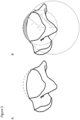
Figure 5 shows an illustration of a colpased talar dome caused by arthritic changes (A), and restoration of the talar dome according to some embodiments of the present invention (B). r1 and r2 are arcs aligned aling the sagittal plane, defining the articular surface (r1) and inferior surface (r2) of the talar implant according to some embodiments of the present invention. -
Figure 6 shows a comparison of normal ankle plantarflexion and dorsiflexion to patients with OA pre and post total ankle replacement. NAL = Non-affected limb; AFL = Affected limb. -
Figure 7 shows a section plane of a talar bone, showing the first and second widths of talar implants according to some embodiments of the present invention. -
Figure 8 shows a lateral view (A) and a medial view (B) of a talar implant according to some embodiments of the present invention. -
Figure 9 shows medial views of a talar implant according to some embodiments of the present invention. r1 denotes the at least one first radius. r2 denotes the at least one second radius, t1 denotes the thickness of the talar implant at the plane where the center of the arc having the at least one radius and the sencer of the arc having the at least one second radius align. T2 denotes the thickness of the talar implant at the anterior portion. -
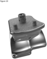
Figure 10 shows a talar implant and a tibial base component according to some embodiments of the present invention. -
Figure 11 shows medial views (top row), and a plan view (bottom row) of a plurality of talar implants in a kit according to some embodiments of the present invention. - For clarity of disclosure, and not by way of limitation, the detailed description of the invention is divided into the following subsections that describe or illustrate certain features, embodiments or applications of the present invention.
- Referring to
Figure 1 , the ankle joint is made up primarily of six bones; the talus, navicular bone, tibia, calcaneus, cuboid, and fibula. A majority of the flexion motion (approximately 75%) comes from the tibio-talar joint, the remainder (approximately 25%) is produced in the forefoot. The inversion/eversion motion comes primarily from the subtalar joint (articulation between the underside of the talus and the calcaneus). - The ligamentous structures surrounding the tibio-talar joint (also referred to as the talocrural joint) act to stabilize the joint through the range of motion. The medial side of the joint is covered by a large group of ligaments referred to as the deltoid ligament. This is comprised of three different ligaments, the posterior tibiotalar (PTT) ligament, tibiocalcaneal (TC) ligament, anterior tibiotalar (ATT) ligament (see
Figure 2B ). The lateral side has three primary ligaments, the anterior talofibular (ATF) ligament, calcaneofibular (CF) ligament, and posterior talofibular (PTF) ligament (seeFigure 2A ). The TC ligament on the medial side and the CF ligament on the lateral side remain roughly isometric throughout the range of motion. This allows for calculating the two-dimensional instant center of the joint through the range of motion. Without being limited to any partculat theory, it is believed that the tibio-talar joint moves in a combination of rolling and sliding. However, a rough approximation of the instant centers on the medial and lateral side are the middle of the TC ligament and the tip of the lateral facet (just distal to the tip of the fibula) respectively. Connecting these points forms the "axis" of the ankle joint throughout the range of motion. -
Figures 3A and 3B illustrate the posterior and lateral muscular structures surrounding the ankle joint.Figures 4A and 4B illustrate the anterior and lateral muscles surrounding the ankle joint. The primary plantarflexor of the ankle is the gastrocnemius muscle, which attaches to the posterior calcaneus through the Achilles tendon. Dorsiflexion is driven by a combination of the extensor digitorum longus and extensor hallucis longus. While these muscles insert to the anterior of the foot, the retinacula (both superior and inferior) act to contour the ligaments to the foot and limit the moment arm of the muscles relative to the talocrural joint. - Post-traumatic osteoarthritis ("OA") in the ankle is the most common form of OA occurring in the ankle joint. Degeneration is usually caused by malalignment in the joint, resulting from bony or soft tissue injury (e.g. fracture or recurrent sprains), leading to asymmetric loading in the joint and degeneration of the cartilage. Once the cartilage is lost, the bone-on-bone articulation deforms the articular surfaces of the joint through plastic deformation and osteophyte formation and alters joint kinematics. Typically, the tibial plafond expands in the A/P dimension as it is flattened by bone-on-bone articulation. Simultaneously, the talus collapses and flattens (see
Figure 5A ) to maintain congruency with the new shape of the tibial plafond. - Flattening the articular surfaces changes the position of the center of rotation through the range of motion by shifting it distal relative to its natural position. The collapse shortens the ligaments that are in line with the tibial shaft (primarily the TC ligament and the CF ligament). Reducing this distance shifts the joint line distally and creates laxity in the ligaments allowing the talus to slide in the anterior and posterior as opposed to rotating properly. When the talus is free to slide in the anterior-posterior ("A/P") direction, there is less constraint so the muscles produce less rotation of the foot during gait. The cycle of deformation of the bone driving kinematic changes which induce further deformation creates a positive feedback loop that can severely alter joint function. The shifted joint line and flattened joint motion alter the kinematics which is further compounded by the pain caused by the arthritic changes. The outcome for patients is a contracted gait cycle combined with modified movement strategies to help protect the affected joint. The typical range of motion for healthy ankle joints is greater than 30° while arthritic ankles may be closer to half of that (i.e. 18°).
- With other joints, removing the pain from the joint results in improved function as seen by studies in knees, hips, and shoulders. However, in many cases, the function of the ankle joint does not return to the level of the unaffected side post-operatively indicating the functional loss is not solely caused by pain in the joint (see
Figure 6 ). This is not limited to active range of motion, often intraoperative motion checks demonstrate a restricted motion due to ligament tension around the joint. - Without being limited to any particular theory, it is believed that the tension of the joint in plantarflexion and dorsiflexion is related to the sagittal shape of an implant body and articular geometries. Overtensioning the ligaments surrounding the ankle joint can lead to motion restriction.
- Without being limited to theory, one possible explaination for the reduced restoration of function may be due to implant design. In particular, the tension of the joint in plantarflexion and dorsiflexion angle may be related to the sagittal shape of the articular geometry. Overtensioning the ligaments surrounding the ankle joint can lead to motion restriction.
- For example, using an implant having a uniform thickness, or a chamfer cut inferior surface may require a volume of bone to be removed from the talus. In these instances, failure to remove bone may result in a reconstructed articular surface having an articular curvature that is greater than native anatomy.
- In some embodiments, the present invention provides a talar implant, comprising:
- a. a superior surface, defined by an arc having at least one first radius;
- b. an inferior surface, defined by an arc having at least one second radius,
- c. a lateral side;
- d. a medial side;
- e. a posterior portion having a first width; and
- f. an anterior portion having a second width;
- wherein the implant is configured to restore a joint tension between a tibio-talar joint in a neutral position,
- wherein the superior surface is separated from the inferior surface by a thickness, defining a height of the medial and lateral sides ,
- wherein the at least one first radius is smaller than the at least one second radius,
- wherein the center of the arc having at least one first radius is offset from the center of the arc having at least one second radius in at least one plane of the talar implant selected from the group consisting of: a superior/inferior plane, an anterior/posterior plane, and a medial/lateral plane,
- wherein the inferior surface is configured to attach to a superior surface of the talus, and
- wherein the anterior portion further comprises an extension configured to provide support.
- Without intending to be limited by any particular theory, a talar implant with the superior surface and inferior surfaces being defined with arcs having different radii of curvature may preserve bone stock in the talus and restore the articular surface of the talar dome.
- According to some embodiments, a talar implant of the present invention is sufficiently designed to restore the joint line and maximum tension at the center of the range of motion with the potential to reduce that tension as the joint rotates in the flexion direction. In some embodiments, a talar implant of the present invention has a thickness, that decreases in the anterior and posterior direction. In some embodiments, the decrease in thickness of the implant at the anterior and posterior portions acts to reduce joint tension at the extremes of motion and prevent the joint from being overconstrained without the need for additional ligamentous procedures.
- In some embodiments, the first width is equal to the width of the posterior portion of the posterior surface of the talus. In some embodiments, the second width is equal to the width of the anterior portion of the posterior surface of the talus. Referring to
Figure 7 , the first and second widths are calculated using the dimensions of the talus at the section plane shown. - Referring to
Figure 8 , in some embodiments, the talar implant is sufficiently designed to restore tension to the tibio-talar joint in the neutral position through the use of arcs that are aligned along the mid-plane of the talar implant in the sagittal plane with different radii. In an embodiment, the arc that defines the articular surface has a smaller radius than the arc defining the inferior surface. - Referring to
Figure 9 , in some embodiments, the articulating surface of a talar implant of the present disclosure is defined by an arc with a first radius (r1) and the bone interface surface of the talar implant is defined by an arc with at least one second radius (r2). The first radius (r1) is smaller than the at least one second radius (r2). In the embodiment shown, the centers of both arcs are aligned at the neutral plane of the talar implant (dashed line in Figures 9A and 9B). The center of rotation of the articular surface is located proximal of the center of rotation of the undersurface. As illustrated in the embodiment shown in Figure 9B, the resulting geometry is thickest in the neutral plane (t1) and becomes thinner toward the extremes of the range of motion (t2). Without intending to be limited to any aprticular theory, this configuration provides the highest joint tension at the center of the range of motion but a reduced tension at the extremes potentially reducing the risk of overconstraining the joint. - According to some embodiments, the at least one first radius defines a superior surface of the implant that restores the articular surface of the talar dome.
- According to some embodiments, the at least one second radius defines an inferior surface of the implant that attaches to the superior surface of the talus, and requiring no removal of talar bone stock.
- In some embodiments, the ratio of the at least one first radius to the at least one second radius is less than 1.
- In some embodiments, the ratio of the at least one first radius to the at least one second radius is 0.6. In some embodiments, the ratio of the at least one first radius to the at least one second radius is 0.7. In some embodiments, the ratio of the at least one first radius to the at least one second radius is 0.8. In some embodiments, the ratio of the at least one first radius to the at least one second radius is 0.81. In some embodiments, the ratio of the at least one first radius to the at least one second radius is 0.82. In some embodiments, the ratio of the at least one first radius to the at least one second radius is 0.83. In some embodiments, the ratio of the at least one first radius to the at least one second radius is 0.84. In some embodiments, the ratio of the at least one first radius to the at least one second radius is 0.85. In some embodiments, the ratio of the at least one first radius to the at least one second radius is 0.9. In some embodiments, the ratio of the at least one first radius to the at least one second radius is 0.91. In some embodiments, the ratio of the at least one first radius to the at least one second radius is 0.92. In some embodiments, the ratio of the at least one first radius to the at least one second radius is 0.93. In some embodiments, the ratio of the at least one first radius to the at least one second radius is 0.94. In some embodiments, the ratio of the at least one first radius to the at least one second radius is 0.95.
- In some embodiments, the at least one first radius is from 15.0 mm to 20.0 mm.
- In some embodiments, the at least one first radius is from 17.0 mm to 18.0 mm.
- In some embodiments, the at least one first radius is 15.0 mm. In some embodiments, the at least one first radius is 16.0 mm. In some embodiments, the the at least one first radius is 17.0 mm. In some embodiments, the at least one first radius is 18.0 mm. In some embodiments, the at least one first radius is 19.0 mm. In some embodiments, the at least one first radius is 20.0 mm.
- In some embodiments, the at least one second radius is from 22.0 mm to 30.0 mm.
- In some embodiments, the at least one second radius is from 23.0 mm to 27.0 mm.
- In some embodiments, the at least one first radius is 15.0 mm. In some embodiments, the at least one second radius is 22.0 mm. In some embodiments, the at least one first radius is 15.0 mm. In some embodiments, the at least one second radius is 23.0 mm. In some embodiments, the at least one first radius is 15.0 mm. In some embodiments, the at least one second radius is 24.0 mm. In some embodiments, the at least one first radius is 15.0 mm. In some embodiments, the at least one second radius is 25.0 mm. In some embodiments, the at least one first radius is 15.0 mm. In some embodiments, the at least one second radius is 26.0 mm. In some embodiments, the at least one first radius is 15.0 mm. In some embodiments, the at least one second radius is 27.0 mm. In some embodiments, the at least one first radius is 15.0 mm. In some embodiments, the at least one second radius is 28.0 mm. In some embodiments, the at least one first radius is 15.0 mm. In some embodiments, the at least one second radius is 29.0 mm. In some embodiments, the at least one first radius is 15.0 mm. In some embodiments, the at least one second radius is 30.0 mm.
- In some embodiments controlling tension across the tibio-talar joint joint by varying thickness may be created using multiple radii of curvature in the sagittal view to achieve a design whose thickness varies from the center of the range of motion to the limits of the range of motion in a desired way. In some embodiments, a spherical radius or radii may be used to create the desired effect around a center point rather than center axis.
- In some embodiments, the center of the arc having at least one first radius is offset from the center of the arc having at least one second radius in at least one plane of the talar implant selected from the group consisting of: a superior/inferior plane, an anterior/posterior plane, and a medial/lateral plane.
- In some embodiments, the center of the arc having at least one first radius is offset from the center of the arc having at least one second radius in the superior/inferior plane.
- In some embodiments, the center of the arc having at least one first radius is offset from the center of the arc having at least one second radius in the anterior/posterior plane.
- In some embodiments, the center of the arc having at least one first radius is offset from the center of the arc having at least one second radius in the medial/lateral plane.
- In some embodiments, the offset of the center of the arc having at least one first radius from the center of the arc having at least one second radius is different on the superior surface of the implant than the offset on the inferior surface of the implant.
- In some embodiments, the offset of the center of the arc having at least one first radius from the center of the arc having at least one second radius is different on the medial side of the implant than the offset on the lateral side of the implant.
- In some embodiments, the offset of the center of the arc having at least one first radius from the center of the arc having at least one second radius is different on the superior portion of the implant than the offset on the anterior portion of the implant.
- Referring to
Figure 10 , in some embodiments, the superior surface of the implant is bicondylar. In some embodiments, the mismatch between surfaces accomadates internal/external, inversion/eversion, medial/lateral, and anterior/posterior motion. The two bearing surfaces have different cross-sections (meaning one has a single radius while the other has multiple radii). - In some embodiments, the at least one first radius varies from the medial side of the implant to the lateral side of the implant. In some embodiments, the ratio of the medial first radius to the lateral first radius is 1.10.
- In some embodiments, the at least one second radius varies from the medial side of the implant to the lateral side of the implant.
- In some embodiments, the tibila base component is configured to attach to the distal tibia after a transverse cut is made and three peg holes are prepared. In some embodiments, the tibial base is symmetrical, allowing it to be used for both right and left ankles.
- In some embodiments, the talar implant is manufactured from a cobalt-chromium alloy having a trabecular metal distal surface. Alternatively, in some embodiments, the talar implant includes a thin interlayer of titanium.
- In some embodiments, the inferior surface further comprises at least one peg configured to anchor the talar implant to the superior surface of the talus.
- In some embodiments, the tibial base component is made from a titanium alloy diffusion bonded to a trabecular metal surface. In some embodiments, the proximal surface of the tibila base component includes three pegs to facilitate stability. Although not visible, an articular surface, manufactured from a polyethylene material, may be mounted to the undersurface of the tibial base component. The polyethylene articular surface can be available in different thicknesses to facilitate proper ligament balancing. The polyethylene articular surface articulates with a talar component (implant) of the present disclosure (bottom component).
- In some embodiments, an implant configured according to the present inventon may be utilized in other joints aside from the ankle including, but not limited to, shoulder, knee, hip, spine, fingers or toes.
- Referring to
Figure 11 , in some embodiments, the present invention provides a kit, comprising a plurality of talar implants,
wherein an individual talar implant of claim 1 within the plurality differs in at least one property selected from the group consisting of: the at least one first radius, the at least one second radius, the first width, the second width, the offset of the center of the arc having at least one first radius from the center of the arc having at least one second radius in the superior/inferior plane, the offset of the center of the arc having at least one first radius from the center of the arc having at least one second radius in the anterior/posterior plane, and the offset of the center of the arc having at least one first radius from the center of the arc having at least one second radius in the medial/lateral plane, from any of the other individual talar implants of claim 1 within the plurality. - In some embodiments, the kit further comprises a tibial base component.
- According to some embodiments, an individual talar implant is selected having the at least one first radius defines a superior surface of the implant that restores the articular surface of the talar dome.
According to some embodiments, an individual talar implant is selected the at least one second radius defines an inferior surface of the implant that attaches to the superior surface of the talus, and requiring no removal of talar bone stock.
Claims (15)
- A talar implant, comprising:a. a superior surface, defined by an arc having at least one first radius (ri);b. an inferior surface, defined by an arc having at least one second radius (rz),c. a lateral side;d. a medial side;e. a posterior portion having a first width; andf. an anterior portion having a second width;wherein the implant is configured to restore a joint tension between a tibio-talar joint in a neutral position,wherein the superior surface is separated from the inferior surface by a thickness, defining a height of the medial and lateral sides,wherein the at least one first radius (r1) is smaller than the at least one second radius (r2),wherein the center of the arc having at least one first radius (r1) is offset from the center of the arc having at least one second radius (r2) in at least one plane of the talar implant selected from the group consisting of: a superior/inferior plane, an anterior/posterior plane, and a medial/lateral plane,wherein the inferior surface is configured to attach to a superior surface of the talus, andwherein the anterior portion further comprises an extension configured to provide support,characterized in that
a ratio of the at least one first radius to the at least one second radius is in the range of from about 0.60 to about 0.95. - The talar implant of claim 1,
wherein the superior surface of the implant is bicondylar. - The talar implant of claim 1 or 2,
wherein the at least one first radius (r1) varies from the medial side of the implant to the lateral side of the implant. - The talar implant of one of claims 1 to 3,
wherein the at least one second radius (rz) varies from the medial side of the implant to the lateral side of the implant. - The talar implant of one of claims 1 to 4,
wherein the inferior surface further comprises at least one peg configured to anchor the talar implant to the superior surface of the talus. - The talar implant of one of claims 1 to 5,
wherein the center of the arc having at least one first radius (r1) is offset from the center of the arc having at least one second radius (r2) in the superior/inferior plane. - The talar implant of one of claims 1 to 6,
wherein the center of the arc having at least one first radius (r1) is offset from the center of the arc having at least one second radius (r2) in the anterior/posterior plane. - The talar implant of one of claims 1 to 7,
wherein the center of the arc having at least one first radius (r1) is offset from the center of the arc having at least one second radius (r2) in the medial/lateral plane. - The talar implant of one of claims 1 to 8,
wherein the offset of the center of the arc having at least one first radius (r1) from the center of the arc having at least one second radius (r2) is different on the superior surface of the implant than the offset on the inferior surface of the implant. - The talar implant of one of claims 1 to 9,wherein the offset of the center of the arc having at least one first radius (r1) from the center of the arc having at least one second radius (r2) is different on the medial side of the implant than the offset on the lateral side of the implant; orwherein, the offset of the center of the arc having at least one first radius (r1) from the center of the arc having at least one second radius (r2) is different on the superior portion of the implant than the offset on the anterior portion of the implant.
- The talar implant of one of claims 1 to 10,
wherein the ratio of the at least one first radius (r1) to the at least one second radius (r2) is less than 1. - The talar implant of one of claims 1 to 11,
wherein the at least one first radius (r1) is from 15.0 mm to 20.0 mm. - The talar implant of one of claims 1 to 12,
wherein the second radius (r2) is from 22.0 mm to 30.0 mm. - A kit, comprising a plurality of the talar implants of one of claims 1 to 13,
wherein an individual talar implant of one of claims 1 to 13 within the plurality differs in at least one property selected from the group consisting of: the at least one first radius (r1), the at least one second radius (r2), the first width, the second width, the offset of the center of the arc having at least one first radius (r1) from the center of the arc having at least one second radius (r2) in the superior/inferior plane, the offset of the center of the arc having at least one first radius (r1) from the center of the arc having at least one second radius (r2) in the anterior/posterior plane, and the offset of the center of the arc having at least one first radius (r1) from the center of the arc having at least one second radius (r2) in the medial/lateral plane, from any of the other individual talar implants of claim 1 within the plurality. - The kit of claim 14,
further comprising a tibial base component.
Applications Claiming Priority (1)
| Application Number | Priority Date | Filing Date | Title |
|---|---|---|---|
| PCT/US2016/014078 WO2017127067A1 (en) | 2016-01-20 | 2016-01-20 | Talar implant for modifying joint kinematics |
Publications (3)
| Publication Number | Publication Date |
|---|---|
| EP3405144A1 EP3405144A1 (en) | 2018-11-28 |
| EP3405144A4 EP3405144A4 (en) | 2020-06-10 |
| EP3405144B1 true EP3405144B1 (en) | 2023-10-25 |
Family
ID=59362071
Family Applications (1)
| Application Number | Title | Priority Date | Filing Date |
|---|---|---|---|
| EP16886708.3A Active EP3405144B1 (en) | 2016-01-20 | 2016-01-20 | Talar implant for modifying joint kinematics |
Country Status (4)
| Country | Link |
|---|---|
| EP (1) | EP3405144B1 (en) |
| JP (1) | JP6704917B2 (en) |
| ES (1) | ES2969812T3 (en) |
| WO (1) | WO2017127067A1 (en) |
Families Citing this family (2)
| Publication number | Priority date | Publication date | Assignee | Title |
|---|---|---|---|---|
| AU2019302325B2 (en) | 2018-04-24 | 2024-05-02 | Paragon 28, Inc. | Implants and methods of use and assembly |
| CN113440321B (en) * | 2021-07-06 | 2022-06-07 | 四川大学华西医院 | Wing type medial and lateral ankle adjustable tumor semi-ankle joint prosthesis |
Family Cites Families (12)
| Publication number | Priority date | Publication date | Assignee | Title |
|---|---|---|---|---|
| US4470158A (en) * | 1978-03-10 | 1984-09-11 | Biomedical Engineering Corp. | Joint endoprosthesis |
| FR2800601B1 (en) * | 1999-11-05 | 2002-01-04 | Europ Foot Platform | ANKLE PROSTHESIS |
| JP4440212B2 (en) * | 2003-10-02 | 2010-03-24 | コンセプツ・イン・メディシン・サード・エルエルシー | Hip joint prosthesis |
| WO2005037135A2 (en) * | 2003-10-14 | 2005-04-28 | The University Of Iowa Research Foundation | Ankle prosthesis and method for implanting ankle prosthesis |
| EP1809209A2 (en) * | 2004-08-19 | 2007-07-25 | Kinetikos Medical Incorporated | Modular total ankle prosthesis apparatuses, systems and methods, and systems and methods for bone resection and prosthetic implantation |
| AT502926B1 (en) * | 2004-11-08 | 2011-04-15 | Alphamed Medizintechnik Fischer Gmbh | ANKLE PROSTHESIS ELEMENTS |
| GB2477662B (en) * | 2006-12-23 | 2011-12-07 | Corin Ltd | Improvements in and relating to an ankle prosthesis |
| US10398561B2 (en) * | 2007-09-26 | 2019-09-03 | DePuy Synthes Products, Inc. | Talar implant system and method |
| US20100057216A1 (en) * | 2008-07-23 | 2010-03-04 | Jamy Gannoe | System and method for joint resurfacing with dynamic fixation |
| US8668743B2 (en) * | 2010-11-02 | 2014-03-11 | Adam D. Perler | Prosthetic device with multi-axis dual bearing assembly and methods for resection |
| US9011451B2 (en) * | 2013-03-12 | 2015-04-21 | DePuy Synthes Products, Inc. | Instruments for use in the implantation of an ankle prosthesis and method of using the same |
| WO2015175560A1 (en) * | 2014-05-12 | 2015-11-19 | Integra Lifesciences Corporation | Total ankle replacement prosthesis |
-
2016
- 2016-01-20 JP JP2017538409A patent/JP6704917B2/en active Active
- 2016-01-20 WO PCT/US2016/014078 patent/WO2017127067A1/en active Application Filing
- 2016-01-20 ES ES16886708T patent/ES2969812T3/en active Active
- 2016-01-20 EP EP16886708.3A patent/EP3405144B1/en active Active
Also Published As
| Publication number | Publication date |
|---|---|
| EP3405144A4 (en) | 2020-06-10 |
| JP2018523497A (en) | 2018-08-23 |
| EP3405144A1 (en) | 2018-11-28 |
| WO2017127067A1 (en) | 2017-07-27 |
| ES2969812T3 (en) | 2024-05-22 |
| JP6704917B2 (en) | 2020-06-03 |
Similar Documents
| Publication | Publication Date | Title |
|---|---|---|
| US20200060835A1 (en) | Talar implant for modifying joint kinematics | |
| EP1974693B1 (en) | Mobile tibial bearing assembly | |
| US11219529B2 (en) | Stabilized total ankle prosthesis | |
| CN106137469B (en) | Implant for restoring normal range of flexion and knee joint kinematics | |
| Saltzman | Perspective on total ankle replacement | |
| US7387644B2 (en) | Knee joint prosthesis with a femoral component which links the tibiofemoral axis of rotation with the patellofemoral axis of rotation | |
| US7922770B2 (en) | Total knee arthroplasty endoprosthesis with third condyle and rotating polyethylene insert | |
| CN101301231B (en) | Mobile bearing assembly having a non-planar interface | |
| CN101951859B (en) | Artificial knee joint including flection in bearing member | |
| US20060020345A1 (en) | Prosthesis device for the ankle articulation | |
| US20080288080A1 (en) | Knee joint prosthesis | |
| EP1380273A2 (en) | Prosthetic knee system | |
| US11963875B2 (en) | Orthopaedic prosthesis for an interphalangeal joint and associated method | |
| Altman | The ulnar side of the wrist: clinically relevant anatomy and biomechanics | |
| KR102649339B1 (en) | tibial plateau patch | |
| US10182915B2 (en) | Cartilage prosthetic implant | |
| EP3405144B1 (en) | Talar implant for modifying joint kinematics | |
| CN106031667B (en) | Artificial knee joint and tibia component and femur component thereof | |
| US9861372B2 (en) | Prosthetic implant and associated instruments | |
| Celli et al. | The Elbow Joint | |
| Richter | First Metatarsophalangeal Total Joint Arthroplasty | |
| Bronzino et al. | Joint-Articulating Surface Motion |
Legal Events
| Date | Code | Title | Description |
|---|---|---|---|
| STAA | Information on the status of an ep patent application or granted ep patent |
Free format text: STATUS: THE INTERNATIONAL PUBLICATION HAS BEEN MADE |
|
| PUAI | Public reference made under article 153(3) epc to a published international application that has entered the european phase |
Free format text: ORIGINAL CODE: 0009012 |
|
| STAA | Information on the status of an ep patent application or granted ep patent |
Free format text: STATUS: REQUEST FOR EXAMINATION WAS MADE |
|
| 17P | Request for examination filed |
Effective date: 20170803 |
|
| AK | Designated contracting states |
Kind code of ref document: A1 Designated state(s): AL AT BE BG CH CY CZ DE DK EE ES FI FR GB GR HR HU IE IS IT LI LT LU LV MC MK MT NL NO PL PT RO RS SE SI SK SM TR |
|
| AX | Request for extension of the european patent |
Extension state: BA ME |
|
| STAA | Information on the status of an ep patent application or granted ep patent |
Free format text: STATUS: REQUEST FOR EXAMINATION WAS MADE |
|
| DAV | Request for validation of the european patent (deleted) | ||
| DAX | Request for extension of the european patent (deleted) | ||
| A4 | Supplementary search report drawn up and despatched |
Effective date: 20200511 |
|
| RIC1 | Information provided on ipc code assigned before grant |
Ipc: A61F 2/42 20060101AFI20200506BHEP |
|
| STAA | Information on the status of an ep patent application or granted ep patent |
Free format text: STATUS: EXAMINATION IS IN PROGRESS |
|
| 17Q | First examination report despatched |
Effective date: 20210225 |
|
| STAA | Information on the status of an ep patent application or granted ep patent |
Free format text: STATUS: EXAMINATION IS IN PROGRESS |
|
| GRAP | Despatch of communication of intention to grant a patent |
Free format text: ORIGINAL CODE: EPIDOSNIGR1 |
|
| STAA | Information on the status of an ep patent application or granted ep patent |
Free format text: STATUS: GRANT OF PATENT IS INTENDED |
|
| INTG | Intention to grant announced |
Effective date: 20230509 |
|
| GRAS | Grant fee paid |
Free format text: ORIGINAL CODE: EPIDOSNIGR3 |
|
| GRAA | (expected) grant |
Free format text: ORIGINAL CODE: 0009210 |
|
| STAA | Information on the status of an ep patent application or granted ep patent |
Free format text: STATUS: THE PATENT HAS BEEN GRANTED |
|
| AK | Designated contracting states |
Kind code of ref document: B1 Designated state(s): AL AT BE BG CH CY CZ DE DK EE ES FI FR GB GR HR HU IE IS IT LI LT LU LV MC MK MT NL NO PL PT RO RS SE SI SK SM TR |
|
| REG | Reference to a national code |
Ref country code: GB Ref legal event code: FG4D |
|
| REG | Reference to a national code |
Ref country code: CH Ref legal event code: EP |
|
| REG | Reference to a national code |
Ref country code: DE Ref legal event code: R096 Ref document number: 602016083742 Country of ref document: DE |
|
| REG | Reference to a national code |
Ref country code: IE Ref legal event code: FG4D |
|
| PGFP | Annual fee paid to national office [announced via postgrant information from national office to epo] |
Ref country code: GB Payment date: 20231130 Year of fee payment: 9 |
|
| PGFP | Annual fee paid to national office [announced via postgrant information from national office to epo] |
Ref country code: IE Payment date: 20231109 Year of fee payment: 9 Ref country code: FR Payment date: 20231212 Year of fee payment: 9 |
|
| REG | Reference to a national code |
Ref country code: LT Ref legal event code: MG9D |
|
| REG | Reference to a national code |
Ref country code: NL Ref legal event code: MP Effective date: 20231025 |
|
| REG | Reference to a national code |
Ref country code: AT Ref legal event code: MK05 Ref document number: 1623903 Country of ref document: AT Kind code of ref document: T Effective date: 20231025 |
|
| PG25 | Lapsed in a contracting state [announced via postgrant information from national office to epo] |
Ref country code: NL Free format text: LAPSE BECAUSE OF FAILURE TO SUBMIT A TRANSLATION OF THE DESCRIPTION OR TO PAY THE FEE WITHIN THE PRESCRIBED TIME-LIMIT Effective date: 20231025 |
|
| PG25 | Lapsed in a contracting state [announced via postgrant information from national office to epo] |
Ref country code: GR Free format text: LAPSE BECAUSE OF FAILURE TO SUBMIT A TRANSLATION OF THE DESCRIPTION OR TO PAY THE FEE WITHIN THE PRESCRIBED TIME-LIMIT Effective date: 20240126 |
|
| PG25 | Lapsed in a contracting state [announced via postgrant information from national office to epo] |
Ref country code: IS Free format text: LAPSE BECAUSE OF FAILURE TO SUBMIT A TRANSLATION OF THE DESCRIPTION OR TO PAY THE FEE WITHIN THE PRESCRIBED TIME-LIMIT Effective date: 20240225 |
|
| PG25 | Lapsed in a contracting state [announced via postgrant information from national office to epo] |
Ref country code: LT Free format text: LAPSE BECAUSE OF FAILURE TO SUBMIT A TRANSLATION OF THE DESCRIPTION OR TO PAY THE FEE WITHIN THE PRESCRIBED TIME-LIMIT Effective date: 20231025 |
|
| PGFP | Annual fee paid to national office [announced via postgrant information from national office to epo] |
Ref country code: ES Payment date: 20240208 Year of fee payment: 9 |
|
| PG25 | Lapsed in a contracting state [announced via postgrant information from national office to epo] |
Ref country code: AT Free format text: LAPSE BECAUSE OF FAILURE TO SUBMIT A TRANSLATION OF THE DESCRIPTION OR TO PAY THE FEE WITHIN THE PRESCRIBED TIME-LIMIT Effective date: 20231025 |
|
| PGFP | Annual fee paid to national office [announced via postgrant information from national office to epo] |
Ref country code: AT Payment date: 20231227 Year of fee payment: 9 |
|
| PG25 | Lapsed in a contracting state [announced via postgrant information from national office to epo] |
Ref country code: LT Free format text: LAPSE BECAUSE OF FAILURE TO SUBMIT A TRANSLATION OF THE DESCRIPTION OR TO PAY THE FEE WITHIN THE PRESCRIBED TIME-LIMIT Effective date: 20231025 Ref country code: IS Free format text: LAPSE BECAUSE OF FAILURE TO SUBMIT A TRANSLATION OF THE DESCRIPTION OR TO PAY THE FEE WITHIN THE PRESCRIBED TIME-LIMIT Effective date: 20240225 Ref country code: GR Free format text: LAPSE BECAUSE OF FAILURE TO SUBMIT A TRANSLATION OF THE DESCRIPTION OR TO PAY THE FEE WITHIN THE PRESCRIBED TIME-LIMIT Effective date: 20240126 Ref country code: BG Free format text: LAPSE BECAUSE OF FAILURE TO SUBMIT A TRANSLATION OF THE DESCRIPTION OR TO PAY THE FEE WITHIN THE PRESCRIBED TIME-LIMIT Effective date: 20240125 Ref country code: AT Free format text: LAPSE BECAUSE OF FAILURE TO SUBMIT A TRANSLATION OF THE DESCRIPTION OR TO PAY THE FEE WITHIN THE PRESCRIBED TIME-LIMIT Effective date: 20231025 Ref country code: PT Free format text: LAPSE BECAUSE OF FAILURE TO SUBMIT A TRANSLATION OF THE DESCRIPTION OR TO PAY THE FEE WITHIN THE PRESCRIBED TIME-LIMIT Effective date: 20240226 |
|
| PGFP | Annual fee paid to national office [announced via postgrant information from national office to epo] |
Ref country code: DE Payment date: 20231128 Year of fee payment: 9 Ref country code: CH Payment date: 20240201 Year of fee payment: 9 |
|
| REG | Reference to a national code |
Ref country code: ES Ref legal event code: FG2A Ref document number: 2969812 Country of ref document: ES Kind code of ref document: T3 Effective date: 20240522 |
|
| PG25 | Lapsed in a contracting state [announced via postgrant information from national office to epo] |
Ref country code: SE Free format text: LAPSE BECAUSE OF FAILURE TO SUBMIT A TRANSLATION OF THE DESCRIPTION OR TO PAY THE FEE WITHIN THE PRESCRIBED TIME-LIMIT Effective date: 20231025 Ref country code: RS Free format text: LAPSE BECAUSE OF FAILURE TO SUBMIT A TRANSLATION OF THE DESCRIPTION OR TO PAY THE FEE WITHIN THE PRESCRIBED TIME-LIMIT Effective date: 20231025 Ref country code: PL Free format text: LAPSE BECAUSE OF FAILURE TO SUBMIT A TRANSLATION OF THE DESCRIPTION OR TO PAY THE FEE WITHIN THE PRESCRIBED TIME-LIMIT Effective date: 20231025 Ref country code: NO Free format text: LAPSE BECAUSE OF FAILURE TO SUBMIT A TRANSLATION OF THE DESCRIPTION OR TO PAY THE FEE WITHIN THE PRESCRIBED TIME-LIMIT Effective date: 20240125 Ref country code: LV Free format text: LAPSE BECAUSE OF FAILURE TO SUBMIT A TRANSLATION OF THE DESCRIPTION OR TO PAY THE FEE WITHIN THE PRESCRIBED TIME-LIMIT Effective date: 20231025 Ref country code: HR Free format text: LAPSE BECAUSE OF FAILURE TO SUBMIT A TRANSLATION OF THE DESCRIPTION OR TO PAY THE FEE WITHIN THE PRESCRIBED TIME-LIMIT Effective date: 20231025 |
|
| PGFP | Annual fee paid to national office [announced via postgrant information from national office to epo] |
Ref country code: IT Payment date: 20240328 Year of fee payment: 9 |
|
| PG25 | Lapsed in a contracting state [announced via postgrant information from national office to epo] |
Ref country code: DK Free format text: LAPSE BECAUSE OF FAILURE TO SUBMIT A TRANSLATION OF THE DESCRIPTION OR TO PAY THE FEE WITHIN THE PRESCRIBED TIME-LIMIT Effective date: 20231025 |
|
| PG25 | Lapsed in a contracting state [announced via postgrant information from national office to epo] |
Ref country code: CZ Free format text: LAPSE BECAUSE OF FAILURE TO SUBMIT A TRANSLATION OF THE DESCRIPTION OR TO PAY THE FEE WITHIN THE PRESCRIBED TIME-LIMIT Effective date: 20231025 |
|
| REG | Reference to a national code |
Ref country code: DE Ref legal event code: R097 Ref document number: 602016083742 Country of ref document: DE |
|
| PG25 | Lapsed in a contracting state [announced via postgrant information from national office to epo] |
Ref country code: SK Free format text: LAPSE BECAUSE OF FAILURE TO SUBMIT A TRANSLATION OF THE DESCRIPTION OR TO PAY THE FEE WITHIN THE PRESCRIBED TIME-LIMIT Effective date: 20231025 |
|
| PG25 | Lapsed in a contracting state [announced via postgrant information from national office to epo] |
Ref country code: SM Free format text: LAPSE BECAUSE OF FAILURE TO SUBMIT A TRANSLATION OF THE DESCRIPTION OR TO PAY THE FEE WITHIN THE PRESCRIBED TIME-LIMIT Effective date: 20231025 Ref country code: SK Free format text: LAPSE BECAUSE OF FAILURE TO SUBMIT A TRANSLATION OF THE DESCRIPTION OR TO PAY THE FEE WITHIN THE PRESCRIBED TIME-LIMIT Effective date: 20231025 Ref country code: RO Free format text: LAPSE BECAUSE OF FAILURE TO SUBMIT A TRANSLATION OF THE DESCRIPTION OR TO PAY THE FEE WITHIN THE PRESCRIBED TIME-LIMIT Effective date: 20231025 Ref country code: EE Free format text: LAPSE BECAUSE OF FAILURE TO SUBMIT A TRANSLATION OF THE DESCRIPTION OR TO PAY THE FEE WITHIN THE PRESCRIBED TIME-LIMIT Effective date: 20231025 Ref country code: DK Free format text: LAPSE BECAUSE OF FAILURE TO SUBMIT A TRANSLATION OF THE DESCRIPTION OR TO PAY THE FEE WITHIN THE PRESCRIBED TIME-LIMIT Effective date: 20231025 Ref country code: CZ Free format text: LAPSE BECAUSE OF FAILURE TO SUBMIT A TRANSLATION OF THE DESCRIPTION OR TO PAY THE FEE WITHIN THE PRESCRIBED TIME-LIMIT Effective date: 20231025 |
|
| PG25 | Lapsed in a contracting state [announced via postgrant information from national office to epo] |
Ref country code: MC Free format text: LAPSE BECAUSE OF FAILURE TO SUBMIT A TRANSLATION OF THE DESCRIPTION OR TO PAY THE FEE WITHIN THE PRESCRIBED TIME-LIMIT Effective date: 20231025 |
|
| PG25 | Lapsed in a contracting state [announced via postgrant information from national office to epo] |
Ref country code: MC Free format text: LAPSE BECAUSE OF FAILURE TO SUBMIT A TRANSLATION OF THE DESCRIPTION OR TO PAY THE FEE WITHIN THE PRESCRIBED TIME-LIMIT Effective date: 20231025 |
|
| PLBE | No opposition filed within time limit |
Free format text: ORIGINAL CODE: 0009261 |
|
| STAA | Information on the status of an ep patent application or granted ep patent |
Free format text: STATUS: NO OPPOSITION FILED WITHIN TIME LIMIT |
|
| PG25 | Lapsed in a contracting state [announced via postgrant information from national office to epo] |
Ref country code: LU Free format text: LAPSE BECAUSE OF NON-PAYMENT OF DUE FEES Effective date: 20240120 |
|
| PG25 | Lapsed in a contracting state [announced via postgrant information from national office to epo] |
Ref country code: LU Free format text: LAPSE BECAUSE OF NON-PAYMENT OF DUE FEES Effective date: 20240120 |
|
| 26N | No opposition filed |
Effective date: 20240726 |