EP3425834B1 - Method for suppressing inter-subcarrier interference and noise signal, and orthogonal frequency division multiplexing receiver for performing same - Google Patents
Method for suppressing inter-subcarrier interference and noise signal, and orthogonal frequency division multiplexing receiver for performing same Download PDFInfo
- Publication number
- EP3425834B1 EP3425834B1 EP17760236.4A EP17760236A EP3425834B1 EP 3425834 B1 EP3425834 B1 EP 3425834B1 EP 17760236 A EP17760236 A EP 17760236A EP 3425834 B1 EP3425834 B1 EP 3425834B1
- Authority
- EP
- European Patent Office
- Prior art keywords
- snr
- symbol interference
- interference free
- interval
- symbol
- Prior art date
- Legal status (The legal status is an assumption and is not a legal conclusion. Google has not performed a legal analysis and makes no representation as to the accuracy of the status listed.)
- Active
Links
Images





Classifications
-
- H—ELECTRICITY
- H04—ELECTRIC COMMUNICATION TECHNIQUE
- H04J—MULTIPLEX COMMUNICATION
- H04J11/00—Orthogonal multiplex systems, e.g. using WALSH codes
- H04J11/0023—Interference mitigation or co-ordination
- H04J11/005—Interference mitigation or co-ordination of intercell interference
- H04J11/0056—Inter-base station aspects
-
- H—ELECTRICITY
- H04—ELECTRIC COMMUNICATION TECHNIQUE
- H04L—TRANSMISSION OF DIGITAL INFORMATION, e.g. TELEGRAPHIC COMMUNICATION
- H04L25/00—Baseband systems
- H04L25/02—Details ; arrangements for supplying electrical power along data transmission lines
- H04L25/03—Shaping networks in transmitter or receiver, e.g. adaptive shaping networks
- H04L25/03006—Arrangements for removing intersymbol interference
- H04L25/03821—Inter-carrier interference cancellation [ICI]
-
- G—PHYSICS
- G06—COMPUTING OR CALCULATING; COUNTING
- G06F—ELECTRIC DIGITAL DATA PROCESSING
- G06F17/00—Digital computing or data processing equipment or methods, specially adapted for specific functions
- G06F17/10—Complex mathematical operations
- G06F17/14—Fourier, Walsh or analogous domain transformations, e.g. Laplace, Hilbert, Karhunen-Loeve, transforms
-
- H—ELECTRICITY
- H04—ELECTRIC COMMUNICATION TECHNIQUE
- H04J—MULTIPLEX COMMUNICATION
- H04J11/00—Orthogonal multiplex systems, e.g. using WALSH codes
- H04J11/0023—Interference mitigation or co-ordination
- H04J11/0026—Interference mitigation or co-ordination of multi-user interference
- H04J11/0036—Interference mitigation or co-ordination of multi-user interference at the receiver
- H04J11/0046—Interference mitigation or co-ordination of multi-user interference at the receiver using joint detection algorithms
-
- H—ELECTRICITY
- H04—ELECTRIC COMMUNICATION TECHNIQUE
- H04J—MULTIPLEX COMMUNICATION
- H04J11/00—Orthogonal multiplex systems, e.g. using WALSH codes
- H04J11/0023—Interference mitigation or co-ordination
- H04J11/005—Interference mitigation or co-ordination of intercell interference
- H04J11/0059—Out-of-cell user aspects
-
- H—ELECTRICITY
- H04—ELECTRIC COMMUNICATION TECHNIQUE
- H04L—TRANSMISSION OF DIGITAL INFORMATION, e.g. TELEGRAPHIC COMMUNICATION
- H04L27/00—Modulated-carrier systems
- H04L27/26—Systems using multi-frequency codes
- H04L27/2601—Multicarrier modulation systems
- H04L27/2602—Signal structure
- H04L27/2605—Symbol extensions, e.g. Zero Tail, Unique Word [UW]
- H04L27/2607—Cyclic extensions
-
- H—ELECTRICITY
- H04—ELECTRIC COMMUNICATION TECHNIQUE
- H04L—TRANSMISSION OF DIGITAL INFORMATION, e.g. TELEGRAPHIC COMMUNICATION
- H04L27/00—Modulated-carrier systems
- H04L27/26—Systems using multi-frequency codes
- H04L27/2601—Multicarrier modulation systems
- H04L27/2626—Arrangements specific to the transmitter only
- H04L27/2646—Arrangements specific to the transmitter only using feedback from receiver for adjusting OFDM transmission parameters, e.g. transmission timing or guard interval length
-
- H—ELECTRICITY
- H04—ELECTRIC COMMUNICATION TECHNIQUE
- H04L—TRANSMISSION OF DIGITAL INFORMATION, e.g. TELEGRAPHIC COMMUNICATION
- H04L27/00—Modulated-carrier systems
- H04L27/26—Systems using multi-frequency codes
- H04L27/2601—Multicarrier modulation systems
- H04L27/2647—Arrangements specific to the receiver only
-
- H—ELECTRICITY
- H04—ELECTRIC COMMUNICATION TECHNIQUE
- H04L—TRANSMISSION OF DIGITAL INFORMATION, e.g. TELEGRAPHIC COMMUNICATION
- H04L27/00—Modulated-carrier systems
- H04L27/26—Systems using multi-frequency codes
- H04L27/2601—Multicarrier modulation systems
- H04L27/2647—Arrangements specific to the receiver only
- H04L27/2655—Synchronisation arrangements
- H04L27/2662—Symbol synchronisation
- H04L27/2665—Fine synchronisation, e.g. by positioning the FFT window
-
- H—ELECTRICITY
- H04—ELECTRIC COMMUNICATION TECHNIQUE
- H04L—TRANSMISSION OF DIGITAL INFORMATION, e.g. TELEGRAPHIC COMMUNICATION
- H04L5/00—Arrangements affording multiple use of the transmission path
-
- H—ELECTRICITY
- H04—ELECTRIC COMMUNICATION TECHNIQUE
- H04L—TRANSMISSION OF DIGITAL INFORMATION, e.g. TELEGRAPHIC COMMUNICATION
- H04L5/00—Arrangements affording multiple use of the transmission path
- H04L5/003—Arrangements for allocating sub-channels of the transmission path
- H04L5/0058—Allocation criteria
- H04L5/006—Quality of the received signal, e.g. BER, SNR, water filling
-
- H—ELECTRICITY
- H04—ELECTRIC COMMUNICATION TECHNIQUE
- H04L—TRANSMISSION OF DIGITAL INFORMATION, e.g. TELEGRAPHIC COMMUNICATION
- H04L25/00—Baseband systems
- H04L25/02—Details ; arrangements for supplying electrical power along data transmission lines
- H04L25/03—Shaping networks in transmitter or receiver, e.g. adaptive shaping networks
- H04L25/03006—Arrangements for removing intersymbol interference
Definitions
- the present invention relates to a method for suppressing an inter-carrier interference and noise signal and an orthogonal frequency division multiplex (referred to as OFDM hereinafter) receiver for performing the same. More particularly, the present invention relates to a skill for an OFDM receiver to suppress an inter-carrier interference and noise signal.
- OFDM orthogonal frequency division multiplex
- the OFDM uses limited frequencies efficiently to be used for a broadcasting system such as a digital video broadcasting-terrestrial and handheld (DVB-T/H) and a digital multimedia broadcasting (DMB), and it is an influential candidate for fourth-generation communication and next generation broadcasting.
- a broadcasting system such as a digital video broadcasting-terrestrial and handheld (DVB-T/H) and a digital multimedia broadcasting (DMB)
- DMB digital multimedia broadcasting
- a transmitting end of a communication system using the OFDM scheme modulates serial data symbols, demultiplexes the same into parallel data, and performs an inverse fast Fourier transform (IFFT) on the same.
- the transmitting end allocates a plurality of subcarriers to the demultiplexed parallel data, and then transmits resultant data to a receiving end.
- the receiving end performs a fast Fourier transform (referred to as FFT hereinafter) on the received signal to separate a subcarrier from the received signal, multiplexes the parallel data from which the subcarrier is separated into serial data, and demodulates the multiplexed serial data to detect a desired data symbol.
- FFT fast Fourier transform
- FFT output data from the OFDM transmitting end generates inter-carrier interference (referred to as ICI hereinafter) according to a radio channel characteristic.
- ICI inter-carrier interference
- the OFDM receiver may suppress inter-carrier interference and reduce a noise component by using an area where there is no OFDM inter-symbol interference (referred to as ISI hereinafter).
- sample data of the symbol interference free interval and the sample data of the effective symbol interval are summed and in the case of a Frank window, they may be added by using a ratio of the FFT side vs. the symbol interference free interval.
- a method for taking an average by setting respective weight values that correspond to 0.5 can be used. That is, the weight value of 0.5 is respectively provided to the sample data of the symbol interference free interval and the sample data of the effective symbol interval, and the average thereof is calculated.
- This method is similar to equal gain combining (referred to as EGC hereinafter).
- EGC signifies phase-coherent combining of different channels with a substantially equivalent weight value.
- a signal-to-noise ratio (referred to as SNR hereinafter) of the symbol interference free interval may be higher or lower than an SNR of the effective symbol interval.
- FIG. 1 shows a conventional OFDM symbol.
- a change width of channel power of a guard interval and an effective symbol interval is large.
- an OFDM (orthogonal frequency-division multiplexing) receiver circuit can include a GI (Guard Interval) combiner circuit that is configured to adaptively combine data in the GI of an OFDM formatted signal with data included in a predetermined section of an active OFDM symbol.
- GI Guard Interval
- the paper Recovering Signal Energy From the Cyclic Frefix in OFDM by Bottomley et al. discloses that in orthogonal frequency-division multiplexing (OFDM) systems, a cyclic prefix (CP) is often added at the transmitter and discarded at the receiver. When the length of the CP exceeds the delay spread of the channel, a portion of the CP can be used to recover additional signal energy.
- Nyquist windowing techniques have been proposed to recover signal energy, thereby improving performance.
- linear maximum-likelihood (ML) and minimum-mean-square-error (MMSE) approaches are developed, which further improve performance, particularly when the signal-to-noise ratio (SNR) is low.
- Simpler two-valued windowing (TVW) solutions are also provided, which generally employ one or two non-Nyquist windows.
- the present invention has been made in an effort to provide a method for suppressing an inter-carrier interference and noise signal by performing a weighting operation between sample data included in a symbol interference free interval and sample data of an effective symbol interval in a time domain in consideration of a channel change, and an OFDM receiver for performing the same.
- the maximum ratio combining (referred to as MRC hereinafter) diversity effect may be obtained by performing a weighting operation in consideration of the SNR when the FFT input data are generated by using the sample data of the symbol interference free interval and the sample data of the effective symbol interval.
- FIG. 2 shows an example of an OFDM symbol for indicating a guard interval without inter-symbol interference according to an exemplary embodiment of the present invention.
- a random OFDM symbol (referred to as a symbol hereinafter), that is, a (b)-th symbol, includes a guard interval and an effective symbol interval at a front end.
- the effective symbol interval includes a symbol data interval and a guard interval at a rear end.
- a configuration of an OFDM receiver for suppressing ICI and additive white Gaussian noise (referred to as AWGN hereinafter) by using the symbol interference free interval before performance of an FFT operation will now be described according to two exemplary embodiments.
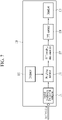
- FIG. 3 shows a block diagram for indicating a configuration of an OFDM receiver according to an exemplary embodiment of the present invention
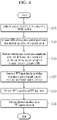
- FIG. 4 shows a flowchart of a method for suppressing an inter-carrier interference and noise signal according to an exemplary embodiment of the present invention
- FIG. 5 shows a drawing for finding correlation energy for estimating a symbol interference free interval according to an exemplary embodiment of the present invention
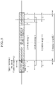
- FIG. 6 shows an example for configuring FFT input data according to an exemplary embodiment of the present invention.
- the OFDM receiver 100 includes a symbol interference free interval estimator 101, an SNR measurer 103, a weighting operator 105, an FFT sampling data controller 107, an FFT operator 109, and an equalizer 111.
- the symbol interference free interval estimator 101 estimates a symbol interference free interval and a number (-) of samples of the symbol interference free interval by using received data S101.
- the symbol interference free interval estimator 101 may use a method using a correlation of the guard interval of the OFDM symbol as shown in FIG. 5 .
- the symbol interference free interval estimator 101 finds correlation energy between the guard interval and the effective symbol interval to find a symbol interference free interval.
- the symbol interference free interval estimator 101 transmits the estimated symbol interference free interval and the number ( ⁇ ) of samples of the symbol interference free interval to the FFT sampling data controller 107.
- the guard interval is a cyclic prefix (CP) of the effective symbol interval, so transmission data of the guard interval are equivalent to transmission data provided in a final area of the effective symbol interval.
- CP cyclic prefix
- the SNR measurer 103 measures each SNR of the symbol interference free interval and the effective symbol interval (S103). For example, the SNR may be calculated by measuring channel power, but the SNR measuring method may be measured by using a method or a device known to the field of the communication industry, which will not be specifically written and no description thereof will be provided.
- the weighting operator 105 performs a weighting operation using the SNRs of the respective intervals between the sample data P1 of the symbol interference free interval and the sample data P3 provided on a rear portion of the corresponding effective symbol interval by using a CP data characteristic (S 105).
- a weighting operation using the SNRs of the respective intervals between the sample data P1 of the symbol interference free interval and the sample data P3 provided on a rear portion of the corresponding effective symbol interval by using a CP data characteristic (S 105).
- n is a time index
- N is an effective symbol interval length
- N G is a guard interval length
- ⁇ is a number of samples on the symbol interference free interval
- y(n) is an output signal of an analog-digital converter (ADC) at an n-th time.
- ADC analog-digital converter
- SNR GI signifies the SNR of the symbol interference free interval
- SNR EFF means the SNR of the effective symbol interval corresponding to the symbol interference free interval
- the weighting operation method may obtain an MRC gain.
- hardware (HW) bit precision for expressing this is increased and a hardware (HW) operation amount may be increased.
- HW hardware bit precision
- a size of the output of the weighting operator 105 may be biased.
- ⁇ signifies a range setting value of the hardware bit precision.
- the FFT sampling data controller 107 configures FFT input data by providing sample data P5 that are weighting-operated between the sample data P1 of the symbol interference free interval and the sample data P3 provided on a rear side of the corresponding effective symbol interval by the weighting operator 105 to a rear side of the effective symbol interval (S107).
- the FFT sampling data controller 107 outputs the FFT input data generated by arranging the weighting-operated sample data P5 to the FFT operator 109.
- FFT IN n ⁇ y n + N G , 0 ⁇ n ⁇ N ⁇ ⁇ out n , N ⁇ ⁇ ⁇ n ⁇ N
- Equation 4 when the FFT input data are expressed as received data, SNR GI and SNR EFF , they are as follows.
- FFT IN n ⁇ y n + N G , 0 ⁇ n ⁇ N ⁇ ⁇ 1 SNR GI + SNR EFF SNR GI ⁇ y n ⁇ N + N G + SNR EFF ⁇ y n + N G , N ⁇ ⁇ ⁇ n ⁇ N
- the FFT operator 109 performs an FFT operation on the FFT input data output by the FFT sampling data controller 120 (S109).
- the equalizer 111 performs channel equalization on a signal output by the FFT operator 109 (Sill).
- a gain that is similar to the MRC diversity may be acquired by using the SNRs of the symbol interference free interval and the effective symbol interval and performing a weighting operation on the respective sample data in an environment in which the change of channel is large.
- FIG. 7 shows a block diagram for indicating a configuration of an OFDM receiver according to another exemplary embodiment of the present invention
- FIG. 8 shows a flowchart of a method for suppressing an inter-carrier interference and noise signal according to another exemplary embodiment of the present invention
- FIG. 9 shows a flowchart of a method for estimating an SNR according to an exemplary embodiment of the present invention
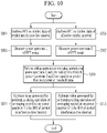
- FIG. 10 shows an example for configuring FFT input data according to another exemplary embodiment of the present invention.
- the OFDM receiver 100' includes a symbol interference free interval estimator 101, a weighting operator 105, an FFT sampling data controller 107, an FFT operator 109, an equalizer 111, and an estimator 113.
- the symbol interference free interval estimator 101 estimates a symbol interference free interval from an OFDM symbol of received data (S201).
- the stage S201 corresponds to the stage S101 of FIG. 4 .
- the estimator 113 estimates an SNR of the symbol interference free interval and an SNR of the effective symbol interval (S203).
- the weighting operator 105 performs a weighting operation between the sample data of the symbol interference free interval and the sample data of the effective symbol interval by using the SNR estimated by the estimator 113 (S205).
- the stage S205 corresponds to the stage S105 of FIG. 4 .
- the FFT sampling data controller 107 provides the weighting-operated sample data P5 to the rear side of the effective symbol interval to configure FFT input data (S207).
- the stage S207 corresponds to the stage S107 of FIG. 4 .
- a calculation of a weight value used to the weighting operation is performed by the estimator 113, which will be described in a latter portion of the present specification.
- the FFT operator 109 performs an FFT operation on the FFT input data generated by arranging the weighting-operated sample data P5 (S209).
- the stage S209 corresponds to the stage S109 of FIG. 4 .
- the equalizer 111 performs channel equalization on the FFT operation result (S211).
- the stage S211 corresponds to the stage S111 of FIG. 4 .
- the estimator 113 estimates an SNR in the time domain. Noise with respect to time does not change much, so it may be assumed that the sample data of the symbol interference free interval and the sample data of the corresponding effective symbol interval may have similar noise. Therefore, power of the time domain data may correspond to the SNR.
- the estimator 113 may indirectly estimate SNR GI and SNR EFF as follows.
- a size component not power
- the size component signifies a summation of absolute values.
- a summation of signal squaring components is performed in the case of using power, but the squaring operation is not performed in the case of using the size component, so it is possible to use a lesser number of hardware bits compared to the use of power, and no process for a squaring operation is needed.
- an average may be taken with the number (-) of samples of the symbol interference free interval or a random scale reduction may be performed.
- the estimator 113 estimates an SNR in a frequency domain.
- a carrier-to-noise ratio (referred to as CNR hereinafter) on the frequency basis between the sample data of the symbol interference free interval and the sample data of the effective symbol interval is inconsistent. Therefore, when a method for indirectly estimating the SNR on the frequency is applied, it is expressed as shown in FIG. 10 .
- the estimator 113 performs an FFT corresponding to the length of the guard interval (GI) on the sample data of the symbol interference free interval and the sample data of the effective symbol interval, respectively (S301) and (S303).
- GI guard interval
- Power spectrum 1 of the FFT result on the sample data of the symbol interference free interval and power spectrum 2 of the FFT result on the sample data of the effective symbol interval are found (S305) and (S307).
- the estimator 113 performs an adding operation (addition) or an averaging operation on the respective power spectrums of subcarriers of which the power spectrums of the FFT result on the sample data of the symbol interference free interval and the FFT result on the sample data of the effective symbol interval are equal to or greater than a predetermined threshold value (S309).
- Values of the adding-operated or averaging-operated power spectrums are estimated to be SNR GI and SNR EFF (S311).
- the estimator 113 estimates the value generated by performing an adding operation or an averaging operation on the power spectrum 1 to be SNR GI , and the value generated by performing an adding operation or an averaging operation on the power spectrum 2 to be SNR EFF for the respective subcarriers of which the power spectrums 1 and 2 are equal to or greater than a threshold value.
- the subcarrier of which the power spectrum is equal to or less than a predetermined threshold value is a subcarrier with a low CNR, it has low reliability, so the subcarrier with a high CNR is used.
- the weighting operator 105 performs a weighting operation in a like manner of Equation 4 or Equation 5 by using the SNR GI and the SNR EFF estimated by the estimator 113.
- the above-described embodiments can be realized through a program for realizing functions corresponding to the configuration of the embodiments or a recording medium for recording the program in addition to through the above-described device and/or method.
Landscapes
- Engineering & Computer Science (AREA)
- Signal Processing (AREA)
- Computer Networks & Wireless Communication (AREA)
- Physics & Mathematics (AREA)
- General Physics & Mathematics (AREA)
- Mathematical Physics (AREA)
- Pure & Applied Mathematics (AREA)
- Data Mining & Analysis (AREA)
- Mathematical Optimization (AREA)
- Computational Mathematics (AREA)
- Theoretical Computer Science (AREA)
- Mathematical Analysis (AREA)
- Databases & Information Systems (AREA)
- Algebra (AREA)
- Software Systems (AREA)
- General Engineering & Computer Science (AREA)
- Power Engineering (AREA)
- Quality & Reliability (AREA)
- Noise Elimination (AREA)
- Discrete Mathematics (AREA)
Description
- The present invention relates to a method for suppressing an inter-carrier interference and noise signal and an orthogonal frequency division multiplex (referred to as OFDM hereinafter) receiver for performing the same. More particularly, the present invention relates to a skill for an OFDM receiver to suppress an inter-carrier interference and noise signal.
- Recently, many studies have been in progress so as to support high-quality and highspeed data transmission in a radio communication environment. Among them, the OFDM uses limited frequencies efficiently to be used for a broadcasting system such as a digital video broadcasting-terrestrial and handheld (DVB-T/H) and a digital multimedia broadcasting (DMB), and it is an influential candidate for fourth-generation communication and next generation broadcasting.
- A transmitting end of a communication system using the OFDM scheme modulates serial data symbols, demultiplexes the same into parallel data, and performs an inverse fast Fourier transform (IFFT) on the same. The transmitting end allocates a plurality of subcarriers to the demultiplexed parallel data, and then transmits resultant data to a receiving end. The receiving end performs a fast Fourier transform (referred to as FFT hereinafter) on the received signal to separate a subcarrier from the received signal, multiplexes the parallel data from which the subcarrier is separated into serial data, and demodulates the multiplexed serial data to detect a desired data symbol.
- In this instance, FFT output data from the OFDM transmitting end generates inter-carrier interference (referred to as ICI hereinafter) according to a radio channel characteristic. Before the OFDM receiver performs an FFT, it may suppress inter-carrier interference and reduce a noise component by using an area where there is no OFDM inter-symbol interference (referred to as ISI hereinafter).
- That is, when the FFT input data for performing an FFT operation is configured, sample data of the guard interval (GI) without ISI in the time domain, that is, the symbol interference free interval and sample data of the effective symbol interval, are summed. An FFT operation on the FFT input data including the summed sample data is performed.
Korean Patent Application Publication 2010-0039467 - In this instance, when the sample data of the symbol interference free interval and the sample data of the effective symbol interval are summed and in the case of a Frank window, they may be added by using a ratio of the FFT side vs. the symbol interference free interval.
- In the case of another existing case, a method for taking an average by setting respective weight values that correspond to 0.5 can be used. That is, the weight value of 0.5 is respectively provided to the sample data of the symbol interference free interval and the sample data of the effective symbol interval, and the average thereof is calculated. This method is similar to equal gain combining (referred to as EGC hereinafter). Here, the EGC signifies phase-coherent combining of different channels with a substantially equivalent weight value.
- However, if the channels are abruptly changed by a mobile environment, a signal-to-noise ratio (referred to as SNR hereinafter) of the symbol interference free interval may be higher or lower than an SNR of the effective symbol interval.
-
FIG. 1 shows a conventional OFDM symbol. - Referring to
FIG. 1 , a change width of channel power of a guard interval and an effective symbol interval is large. - As described, when the channel change is large and a simple summation of the sample data of the symbol interference free interval and the sample data of the effective symbol interval is performed in a like manner of prior art, a problem that the SNR fails to obtain a gain of a large interval is generated.
- In accordance with its abstract, patent document
US8000417B1 discloses that an OFDM (orthogonal frequency-division multiplexing) receiver circuit can include a GI (Guard Interval) combiner circuit that is configured to adaptively combine data in the GI of an OFDM formatted signal with data included in a predetermined section of an active OFDM symbol. - In accordance with its abstract, the paper On Optimum Segment Combining Weight for ICI Self-Cancellation in OFDM Systems under Doubly Selective Fading Channels by Ma et al. discloses that ICI self-cancellation algorithms are promising techniques to mitigate the ICI effect in OFDM systems caused by high mobility. In the area of ICI self-cancellation, the calculation of optimum combining weight is still an open question. In this paper, the problem of finding optimum combining weight to minimize the ICI-plus-noise power is formulated. Then a non-iterative algorithm is derived to find the optimum solution. the performance of the optimum combining weight is compared with other existing combining weight methods.
- In accordance with its abstract, the paper Recovering Signal Energy From the Cyclic Frefix in OFDM by Bottomley et al. discloses that in orthogonal frequency-division multiplexing (OFDM) systems, a cyclic prefix (CP) is often added at the transmitter and discarded at the receiver. When the length of the CP exceeds the delay spread of the channel, a portion of the CP can be used to recover additional signal energy. In the past, Nyquist windowing techniques have been proposed to recover signal energy, thereby improving performance. In this paper, linear maximum-likelihood (ML) and minimum-mean-square-error (MMSE) approaches are developed, which further improve performance, particularly when the signal-to-noise ratio (SNR) is low. Simpler two-valued windowing (TVW) solutions are also provided, which generally employ one or two non-Nyquist windows.
- In accordance with its abstract, the paper A Simple ICI Suppression Method Utilizing Cyclic Prefix for OFDM Systems in the Presence of Phase Noise by Ma et al. proposes an extremely low-complexity inter-carrier interference (ICI) suppression method for OFDM systems in the presence of phase noise. The core idea is to utilize the ISI-free part of cyclic prefix (CP), which is simply ignored in traditional methods. The ISI-free samples in CP are linearly combined with the corresponding samples in the OFDM symbol to suppress ICI, and this scheme is called 'CP combining' through-out this paper. In addition, the optimum combining coefficients, in the sense of ICI power minimization, are derived, and a set of near-optimum coefficients are proposed to reduce the complexity. Simulation results show that the proposed CP combining method improves the system performance by 0.5 - 1.5dB. Furthermore, the proposed method can be incorporated with other phase noise mitigation methods to further improve the system performance.
- The present invention has been made in an effort to provide a method for suppressing an inter-carrier interference and noise signal by performing a weighting operation between sample data included in a symbol interference free interval and sample data of an effective symbol interval in a time domain in consideration of a channel change, and an OFDM receiver for performing the same.
- The technical solution according to the invention is set out in the appended claims.
- According to the exemplary embodiment of the present invention, the maximum ratio combining (referred to as MRC hereinafter) diversity effect may be obtained by performing a weighting operation in consideration of the SNR when the FFT input data are generated by using the sample data of the symbol interference free interval and the sample data of the effective symbol interval.
-
-
FIG. 1 shows a conventional OFDM symbol. -
FIG. 2 shows an example of an OFDM symbol for indicating a guard interval without inter-symbol interference according to an exemplary embodiment. -
FIG. 3 shows a block diagram for indicating a configuration of an OFDM receiver according to an exemplary embodiment. -
FIG. 4 shows a flowchart of a method for suppressing an inter-carrier interference and noise signal according to an exemplary embodiment. -
FIG. 5 shows a drawing for finding correlation energy for estimating a symbol interference free interval according to an exemplary embodiment. -
FIG. 6 shows an example for configuring FFT input data according to an exemplary embodiment of the present invention. -
FIG. 7 shows a block diagram for indicating a configuration of an OFDM receiver according to another exemplary embodiment of the present invention. -
FIG. 8 shows a flowchart of a method for suppressing an inter-carrier interference and noise signal according to another exemplary embodiment of the present invention. -
FIG. 9 shows an example for configuring FFT input data according to another exemplary embodiment of the present invention. -
FIG. 10 shows a flowchart of a method for estimating an SNR according to an exemplary embodiment of the present invention. - The embodiments of
figures 6-10 and the accompanying description are according to the invention. Other embodiments, insofar as these are not in correspondence to the embodiments offigures 6-10 and the accompanying description, are for exemplary purposes only. - In the following detailed description, only certain exemplary embodiments of the present invention have been shown and described, simply by way of illustration. As those skilled in the art would realize, the described embodiments may be modified in various different ways, all without departing from the scope of the present invention. Accordingly, the drawings and description are to be regarded as illustrative in nature and not restrictive. Like reference numerals designate like elements throughout the specification.
- Throughout the specification, unless explicitly described to the contrary, the word "comprise" and variations such as "comprises" or "comprising" will be understood to imply the inclusion of stated elements but not the exclusion of any other elements.
- The suffixes "-er" and "-or" and the term "module" described in the specification mean units for processing at least one function or operation, and can be implemented by hardware or software and combinations thereof. Like reference numerals shown in the drawings indicate like constituent elements.
- A method for suppressing an inter-carrier interference and noise signal and an OFDM receiver for performing the same according to an exemplary embodiment of the present invention will now be described with reference to accompanying drawings.
-
FIG. 2 shows an example of an OFDM symbol for indicating a guard interval without inter-symbol interference according to an exemplary embodiment of the present invention. - Referring to
FIG. 2 , a random OFDM symbol (referred to as a symbol hereinafter), that is, a (b)-th symbol, includes a guard interval and an effective symbol interval at a front end. Although not shown, the effective symbol interval includes a symbol data interval and a guard interval at a rear end. - Here, "the guard interval without ISI" from among the guard interval at the front end will be referred to as a symbol interference free interval. τmax represents a maximum delay time of a channel, and is inversely proportional (Δ=NG-τmax) to the maximum delay time of the symbol interference free interval.
- A configuration of an OFDM receiver for suppressing ICI and additive white Gaussian noise (referred to as AWGN hereinafter) by using the symbol interference free interval before performance of an FFT operation will now be described according to two exemplary embodiments.
- A first exemplary embodiment is to use an actually measured SNR.
FIG. 3 shows a block diagram for indicating a configuration of an OFDM receiver according to an exemplary embodiment of the present invention,FIG. 4 shows a flowchart of a method for suppressing an inter-carrier interference and noise signal according to an exemplary embodiment of the present invention,FIG. 5 shows a drawing for finding correlation energy for estimating a symbol interference free interval according to an exemplary embodiment of the present invention, andFIG. 6 shows an example for configuring FFT input data according to an exemplary embodiment of the present invention. - Referring to
FIG. 3 andFIG. 4 , theOFDM receiver 100 includes a symbol interferencefree interval estimator 101, anSNR measurer 103, aweighting operator 105, an FFTsampling data controller 107, anFFT operator 109, and anequalizer 111. - The symbol interference
free interval estimator 101 estimates a symbol interference free interval and a number (-) of samples of the symbol interference free interval by using received data S101. - Here, according to one exemplary embodiment, the symbol interference
free interval estimator 101 may use a method using a correlation of the guard interval of the OFDM symbol as shown inFIG. 5 . - Referring to
FIG. 5 , the symbol interferencefree interval estimator 101 finds correlation energy between the guard interval and the effective symbol interval to find a symbol interference free interval. - The symbol interference
free interval estimator 101 calculates the correlation energy while changing the number of samples, so as to find the correlation energy. For example,correlation energy 0 corresponds to the number of samples = NG. When there is a channel impulse response, the correlation energy is operated to be the highest, so the symbol interferencefree interval estimator 101 uses the correlation energy operated to be the highest to find a symbol interference free interval. That is, when the correlation energy Δ-1 is operated to be the highest, the guard interval where the correlation energy Δ-1 is calculated may be estimated to be a symbol interference free interval. The symbol interferencefree interval estimator 101 transmits the estimated symbol interference free interval and the number (Δ) of samples of the symbol interference free interval to the FFTsampling data controller 107. - The guard interval is a cyclic prefix (CP) of the effective symbol interval, so transmission data of the guard interval are equivalent to transmission data provided in a final area of the effective symbol interval.
- The SNR measurer 103 measures each SNR of the symbol interference free interval and the effective symbol interval (S103). For example, the SNR may be calculated by measuring channel power, but the SNR measuring method may be measured by using a method or a device known to the field of the communication industry, which will not be specifically written and no description thereof will be provided.
- The
weighting operator 105 performs a weighting operation using the SNRs of the respective intervals between the sample data P1 of the symbol interference free interval and the sample data P3 provided on a rear portion of the corresponding effective symbol interval by using a CP data characteristic (S 105). Through the above-noted weighting operation, a differential component and a noise component of a radio channel may be reduced, and the SNR may acquire a gain of a large interval in an environment with a large channel change. - Here, when a received symbol is modeled, it becomes as follows.

- Here, n is a time index, N is an effective symbol interval length, NG is a guard interval length, Δ is a number of samples on the symbol interference free interval, and y(n) is an output signal of an analog-digital converter (ADC) at an n-th time.
- When the symbol interference free interval of the received symbol is modeled, it becomes as follows.

- When the effective symbol interval of the received symbol is modeled, it becomes as follows.

- An output (out[n]) of the
weighting operator 105 is as follows.
- Here, it is given that N-Δ≤n≤N.
- In this instance, SNRGI signifies the SNR of the symbol interference free interval, and SNREFF means the SNR of the effective symbol interval corresponding to the symbol interference free interval.
- The weighting operation method may obtain an MRC gain. However, when a difference between SNRGI and SNREFF is very large, hardware (HW) bit precision for expressing this is increased and a hardware (HW) operation amount may be increased. When the hardware bit precision is insufficient, a size of the output of the
weighting operator 105 may be biased. - As described above, when the difference between SNRGI and SNREFF is very large, that is, when it is greater than a predetermined threshold value, the hardware operation amount is reduced by setting a range for a ratio of SNRGI and SNREFF with limited hardware bit precision.

- Here, α signifies a range setting value of the hardware bit precision.
- The FFT
sampling data controller 107 configures FFT input data by providing sample data P5 that are weighting-operated between the sample data P1 of the symbol interference free interval and the sample data P3 provided on a rear side of the corresponding effective symbol interval by theweighting operator 105 to a rear side of the effective symbol interval (S107). The FFTsampling data controller 107 outputs the FFT input data generated by arranging the weighting-operated sample data P5 to theFFT operator 109. - Here, the FFT input data are as follows.

- In the case of applying Equation 4 to Equation 6, when the FFT input data are expressed as received data, SNRGI and SNREFF, they are as follows.

- The
FFT operator 109 performs an FFT operation on the FFT input data output by the FFT sampling data controller 120 (S109). - The
equalizer 111 performs channel equalization on a signal output by the FFT operator 109 (Sill). - As described above, a gain that is similar to the MRC diversity may be acquired by using the SNRs of the symbol interference free interval and the effective symbol interval and performing a weighting operation on the respective sample data in an environment in which the change of channel is large.
- Further, another exemplary embodiment is a method for estimating the SNR in an actual environment, and
FIG. 7 shows a block diagram for indicating a configuration of an OFDM receiver according to another exemplary embodiment of the present invention,FIG. 8 shows a flowchart of a method for suppressing an inter-carrier interference and noise signal according to another exemplary embodiment of the present invention,FIG. 9 shows a flowchart of a method for estimating an SNR according to an exemplary embodiment of the present invention, andFIG. 10 shows an example for configuring FFT input data according to another exemplary embodiment of the present invention. - In this instance, constituent elements that are the same as those in the configuration shown with reference to
FIG. 3 will use same reference numerals, and operations that are the same as those shown with reference toFIG. 3 will not be described. - Referring to
FIG. 7 , the OFDM receiver 100' includes a symbol interferencefree interval estimator 101, aweighting operator 105, an FFTsampling data controller 107, anFFT operator 109, anequalizer 111, and anestimator 113. - Referring to
FIG. 8 , the symbol interferencefree interval estimator 101 estimates a symbol interference free interval from an OFDM symbol of received data (S201). The stage S201 corresponds to the stage S101 ofFIG. 4 . - The
estimator 113 estimates an SNR of the symbol interference free interval and an SNR of the effective symbol interval (S203). - The
weighting operator 105 performs a weighting operation between the sample data of the symbol interference free interval and the sample data of the effective symbol interval by using the SNR estimated by the estimator 113 (S205). The stage S205 corresponds to the stage S105 ofFIG. 4 . - As shown in
FIG. 9 , the FFTsampling data controller 107 provides the weighting-operated sample data P5 to the rear side of the effective symbol interval to configure FFT input data (S207). The stage S207 corresponds to the stage S107 ofFIG. 4 . However, a calculation of a weight value used to the weighting operation is performed by theestimator 113, which will be described in a latter portion of the present specification. - The
FFT operator 109 performs an FFT operation on the FFT input data generated by arranging the weighting-operated sample data P5 (S209). The stage S209 corresponds to the stage S109 ofFIG. 4 . - The
equalizer 111 performs channel equalization on the FFT operation result (S211). The stage S211 corresponds to the stage S111 ofFIG. 4 . - Here, according to an exemplary embodiment not according to the invention, the
estimator 113 estimates an SNR in the time domain. Noise with respect to time does not change much, so it may be assumed that the sample data of the symbol interference free interval and the sample data of the corresponding effective symbol interval may have similar noise. Therefore, power of the time domain data may correspond to the SNR. - Hence, the
estimator 113 may indirectly estimate SNRGI and SNREFF as follows.

- In this instance, to simplify the hardware (HW), a size component, not power, may be used. Here, the size component signifies a summation of absolute values. A summation of signal squaring components is performed in the case of using power, but the squaring operation is not performed in the case of using the size component, so it is possible to use a lesser number of hardware bits compared to the use of power, and no process for a squaring operation is needed.
- Further, to reduce the hardware bit precision, an average may be taken with the number (-) of samples of the symbol interference free interval or a random scale reduction may be performed.
- According to an exemplary embodiment according to the invention, the
estimator 113 estimates an SNR in a frequency domain. In a multi-channel environment or a condition where different kinds of noise are provided, a carrier-to-noise ratio (referred to as CNR hereinafter) on the frequency basis between the sample data of the symbol interference free interval and the sample data of the effective symbol interval is inconsistent. Therefore, when a method for indirectly estimating the SNR on the frequency is applied, it is expressed as shown inFIG. 10 . - Referring to
FIG. 10 , theestimator 113 performs an FFT corresponding to the length of the guard interval (GI) on the sample data of the symbol interference free interval and the sample data of the effective symbol interval, respectively (S301) and (S303). -
Power spectrum 1 of the FFT result on the sample data of the symbol interference free interval andpower spectrum 2 of the FFT result on the sample data of the effective symbol interval are found (S305) and (S307). - The
estimator 113 performs an adding operation (addition) or an averaging operation on the respective power spectrums of subcarriers of which the power spectrums of the FFT result on the sample data of the symbol interference free interval and the FFT result on the sample data of the effective symbol interval are equal to or greater than a predetermined threshold value (S309). Values of the adding-operated or averaging-operated power spectrums are estimated to be SNRGI and SNREFF (S311). - That is, the
estimator 113 estimates the value generated by performing an adding operation or an averaging operation on thepower spectrum 1 to be SNRGI, and the value generated by performing an adding operation or an averaging operation on thepower spectrum 2 to be SNREFF for the respective subcarriers of which thepower spectrums - Here, the subcarrier of which the power spectrum is equal to or less than a predetermined threshold value is a subcarrier with a low CNR, it has low reliability, so the subcarrier with a high CNR is used.
- The
weighting operator 105, as described above, performs a weighting operation in a like manner of Equation 4 or Equation 5 by using the SNRGI and the SNREFF estimated by theestimator 113. - The above-described embodiments can be realized through a program for realizing functions corresponding to the configuration of the embodiments or a recording medium for recording the program in addition to through the above-described device and/or method.
Claims (6)
- A method for an orthogonal frequency division multiplex, OFDM, receiver to suppress an inter-carrier interference and noise signal in data received by the receiver by using a symbol interference free interval without inter-symbol interference, ISI, in a guard interval ,GI, of a received OFDM symbol, comprising:performing (S301, S303) FFT corresponding to a length of the GI on sample data of the symbol interference free interval and sample data of a rear portion (P3) corresponding to the symbol interference free interval of a corresponding effective symbol interval of the received OFDM symbol;measuring (S305) a first power spectrum of FFT result on the sample data of the symbol interference free interval and measuring (S307) a second power spectrum of FFT result on the sample data of the rear portion;estimating (S311) a value generated by performing (S309) an adding operation or an averaging operation on the first power spectrum to be a signal-to-noise ratio, SNR, of the symbol interference free interval and estimating (S313) a value generated by performing (S309) an adding operation or an averaging operation on the second power spectrum to be a SNR of the rear portion, for at least one subcarrier of which the first power spectrum and the second power spectrum are equal to or greater than a predetermined threshold value;performing (S105) a weighting operation between the sample data of the symbol interference free interval (S301) and the sample data of the rear portion (S303) by using the estimated SNR of the symbol interference free interval and the estimated SNR of the rear portion; andgenerating (S107) FFT input data from the received data by including into the effective symbol interval of the received data the weighting-operated sample data;performing (S109) an FFT on the FFT input data.
- The method of claim 1, whereinthe performing a weighting operation comprises using a first operation value generated by applying a weight coefficient to the signal modeled as the symbol interference free interval, a second operation value generated by applying a weight coefficient to the signal modeled as the rear portion corresponding to the symbol interference free interval, and a value generated by summing the SNR of the symbol interference free interval and the SNR of the rear portion,wherein the weight coefficient of the first operation value is the SNR of the symbol interference free interval, andwherein the weight coefficient of the second operation value is the SNR of the rear portion.
- The method of claim 2, wherein
the weighting operation comprises setting a range setting value, α, in case of limited hardware bit precision and to apply the range setting value (α) to each weight coefficient of the weighting operation that uses the SNR of the symbol interference free interval and the SNR of the rear portion. - An orthogonal frequency division multiplex, OFDM, receiver (100), wherein the OFDM receiver is configured to:perform FFT corresponding to a length of the GI on sample data of the symbol interference free interval and sample data of a rear portion corresponding to the symbol interference free interval of a corresponding effective symbol interval of the received OFDM symbol; andmeasure a first power spectrum of FFT result on the sample data of the symbol interference free interval and measure a second power spectrum of FFT result on the sample data of the rear portion of the corresponding effective symbol interval,the OFDM receiver comprising:an estimator (113) configured to estimate a value generated by performing an adding operation or averaging operation on the first power spectrum to be a signal-to-noise ratio, SNR, of the symbol interference free interval, and to estimate a value generated by performing an adding operation or averaging operation on the second power spectrum to be a SNR of a rear portion corresponding to the symbol interference free interval of the corresponding effective symbol interval, for one subcarrier is in which the first power spectrum and the second spectrum are equal to or greater than a threshold value;a weighting operator (105) configured to perform a weighting operation between the sample data of the symbol interference free interval without inter-symbol interference (ISI) in a guard interval (GI) of an OFDM symbol and the sample data of the rear portion corresponding to the symbol interference free interval by using the estimated SNR of the symbol interference free interval without ISI and the estimated SNR of the rear portion;an FFT sampling data controller (107) configured to perform generating FFT input data from the received data by including into the effective symbol interval the weighting-operated sample data; andan FFT operator (109) configured to perform a FFT operation on the FFT input data.
- The OFDM receiver of claim 4, whereinthe weighting operator (105) is configured to perform the weighting operation using a first operation value generated by applying a weight coefficient to the signal modeled as the symbol interference free interval, a second operation value generated by applying a weight coefficient to the signal modeled as the rear portion corresponding to the symbol interference free interval, and a value generated by summing the SNR of the symbol interference free interval and the SNR of the rear portion,wherein the weight coefficient of the first operation value is the SNR of the symbol interference free interval, andwherein the weight coefficient of the second operation value is the SNR of the rear portion.
- The OFDM receiver of claim 5, wherein
the weighting operator (105) is configured to calculate a range setting value (α) in case of limited hardware bit precision and to apply the range setting value (α) to each weight coefficient of the weighting operation that uses the SNR of the symbol interference free interval and the SNR of the rear portion.
Applications Claiming Priority (2)
| Application Number | Priority Date | Filing Date | Title |
|---|---|---|---|
| KR1020160025906A KR101794987B1 (en) | 2016-03-03 | 2016-03-03 | Inter-carrier interference and noise signal suppression method and orthogonal frequency division multiplexing receiver thereof |
| PCT/KR2017/001776 WO2017150832A1 (en) | 2016-03-03 | 2017-02-17 | Method for suppressing inter-subcarrier interference and noise signal, and orthogonal frequency division multiplexing receiver for performing same |
Publications (3)
| Publication Number | Publication Date |
|---|---|
| EP3425834A1 EP3425834A1 (en) | 2019-01-09 |
| EP3425834A4 EP3425834A4 (en) | 2019-09-25 |
| EP3425834B1 true EP3425834B1 (en) | 2022-08-03 |
Family
ID=59744149
Family Applications (1)
| Application Number | Title | Priority Date | Filing Date |
|---|---|---|---|
| EP17760236.4A Active EP3425834B1 (en) | 2016-03-03 | 2017-02-17 | Method for suppressing inter-subcarrier interference and noise signal, and orthogonal frequency division multiplexing receiver for performing same |
Country Status (5)
| Country | Link |
|---|---|
| US (1) | US10348433B2 (en) |
| EP (1) | EP3425834B1 (en) |
| JP (1) | JP6664521B2 (en) |
| KR (1) | KR101794987B1 (en) |
| WO (1) | WO2017150832A1 (en) |
Families Citing this family (2)
| Publication number | Priority date | Publication date | Assignee | Title |
|---|---|---|---|---|
| CN113098815B (en) * | 2021-03-05 | 2022-04-01 | 华中科技大学 | A frequency domain suppression method and system for underwater acoustic OFDM inter-carrier interference |
| US12438630B2 (en) | 2023-02-14 | 2025-10-07 | Cisco Technology, Inc. | Signal to interference and noise ratio estimation |
Family Cites Families (8)
| Publication number | Priority date | Publication date | Assignee | Title |
|---|---|---|---|---|
| KR100234329B1 (en) * | 1997-09-30 | 1999-12-15 | 윤종용 | FFT window position recovery apparatus for OFDM system receiver and method thereof |
| US7769094B2 (en) * | 2006-11-10 | 2010-08-03 | Telefonaktiebolaget L M Ericsson (Publ) | Arrangement and method for reducing the impact of interfering signals in a communication system |
| US7773683B2 (en) | 2007-08-31 | 2010-08-10 | Industrial Technology Research Institute | Method and apparatus for ICI cancellation in communication systems |
| US8000417B1 (en) * | 2007-11-27 | 2011-08-16 | Samsung Electronics Co., Ltd. | Methods and OFDM receivers providing inter-carrier interference cancellation with guard interval reuse scheme |
| KR20100039467A (en) | 2008-10-08 | 2010-04-16 | 주식회사 텔레칩스 | Inter-carrier interference suppression apparatus in orthogonal frequency division multiplexing receiver and method for the same |
| KR100992327B1 (en) * | 2009-02-18 | 2010-11-05 | 성균관대학교산학협력단 | Frequency Synchronizer in PFDM System |
| KR101232132B1 (en) * | 2011-05-31 | 2013-02-12 | 주식회사 텔레칩스 | Apparatus and method for receiving signal of acquiring antenna diversity in a ofdm system |
| KR101239655B1 (en) | 2012-01-13 | 2013-03-05 | (주)에프씨아이 | Method for adjusting fft window of ofdm system |
-
2016
- 2016-03-03 KR KR1020160025906A patent/KR101794987B1/en active Active
-
2017
- 2017-02-17 US US16/081,968 patent/US10348433B2/en active Active
- 2017-02-17 WO PCT/KR2017/001776 patent/WO2017150832A1/en not_active Ceased
- 2017-02-17 JP JP2018566177A patent/JP6664521B2/en active Active
- 2017-02-17 EP EP17760236.4A patent/EP3425834B1/en active Active
Non-Patent Citations (1)
| Title |
|---|
| CERNA MICHAEL ET AL: "Application Note 041 The Fundamentals of FFT-Based Signal Analysis and Measurement", 1 July 2000 (2000-07-01), pages 1 - 20, XP055816240, Retrieved from the Internet <URL:https://www.sjsu.edu/people/burford.furman/docs/me120/FFT_tutorial_NI.pdf> [retrieved on 20210621] * |
Also Published As
| Publication number | Publication date |
|---|---|
| KR20170103304A (en) | 2017-09-13 |
| US20190123844A1 (en) | 2019-04-25 |
| KR101794987B1 (en) | 2017-11-07 |
| JP6664521B2 (en) | 2020-03-13 |
| US10348433B2 (en) | 2019-07-09 |
| JP2019511180A (en) | 2019-04-18 |
| EP3425834A4 (en) | 2019-09-25 |
| WO2017150832A1 (en) | 2017-09-08 |
| EP3425834A1 (en) | 2019-01-09 |
Similar Documents
| Publication | Publication Date | Title |
|---|---|---|
| KR100996535B1 (en) | Inter-cell interference mitigation method using spatial covariance matrix estimation for multi input and multi output antenna ofdm system, and receiving apparatus using the same | |
| CN101557378B (en) | Method for pilot transmitting, channel estimation and noise power estimation in OFDM system | |
| JP4421416B2 (en) | OFDM receiver | |
| US8223862B2 (en) | OFDM inter-carrier interference cancellation method | |
| CN105337906B (en) | Channel estimation method and device | |
| JP2007228592A (en) | Channel estimation apparatus and method for data demodulation in wireless access system | |
| EP2291967B1 (en) | Apparatus and method for channel estimation in a mobile communication system | |
| CN102158459A (en) | OFDM (Orthogonal Frequency Division Multiplexing) block transmission method based on time-frequency two-dimension training information | |
| EP2409450B1 (en) | Signal processor, receiver and signal processing method | |
| US8477865B2 (en) | MIMO receiving apparatus and method | |
| CN107483373A (en) | A kind of the LMMSE channel estimation methods and device of the weighting of anti-multipath iteration | |
| CN104836770B (en) | It is a kind of based on related average and adding window timing estimation method | |
| KR20090064738A (en) | Receiver and method for single carrier frequency division multiple access system | |
| KR101390317B1 (en) | Apparatus and method for compensation of channel impulse response estimation error in orthogonal frequency division multiplexing systems | |
| EP2311232A1 (en) | A simplified equalizationscheme for distributed resource allocation in multi-carrier systems | |
| WO2012092642A1 (en) | Doppler-assisted channel estimation | |
| US20080181341A1 (en) | Receiver Apparatus | |
| US20180013598A1 (en) | Receiving apparatus and receiving method | |
| EP3425834A1 (en) | Method for suppressing inter-subcarrier interference and noise signal, and orthogonal frequency division multiplexing receiver for performing same | |
| CN102801662B (en) | Superimposed-pilot-based channel estimation method and device for multi-band ultra-wideband system | |
| US7551548B2 (en) | OFDM demodulation apparatus, method and computer readable medium | |
| Suárez-Casal et al. | Experimental assessment of WiMAX transmissions under highly time-varying channels | |
| JP2009141740A (en) | ICI amount estimating apparatus, estimating method, and receiving apparatus using the same | |
| US20150207588A1 (en) | Receiving device and receiving method, and computer program | |
| KR20100070478A (en) | A method for channel and interference estimation in a wireless communication system and an apparatus thereof |
Legal Events
| Date | Code | Title | Description |
|---|---|---|---|
| STAA | Information on the status of an ep patent application or granted ep patent |
Free format text: STATUS: THE INTERNATIONAL PUBLICATION HAS BEEN MADE |
|
| PUAI | Public reference made under article 153(3) epc to a published international application that has entered the european phase |
Free format text: ORIGINAL CODE: 0009012 |
|
| STAA | Information on the status of an ep patent application or granted ep patent |
Free format text: STATUS: REQUEST FOR EXAMINATION WAS MADE |
|
| 17P | Request for examination filed |
Effective date: 20180831 |
|
| AK | Designated contracting states |
Kind code of ref document: A1 Designated state(s): AL AT BE BG CH CY CZ DE DK EE ES FI FR GB GR HR HU IE IS IT LI LT LU LV MC MK MT NL NO PL PT RO RS SE SI SK SM TR |
|
| AX | Request for extension of the european patent |
Extension state: BA ME |
|
| DAV | Request for validation of the european patent (deleted) | ||
| DAX | Request for extension of the european patent (deleted) | ||
| RIN1 | Information on inventor provided before grant (corrected) |
Inventor name: YUN, YOUNG HO Inventor name: YOON, SUKHYUN |
|
| REG | Reference to a national code |
Ref country code: DE Ref legal event code: R079 Ref document number: 602017060212 Country of ref document: DE Free format text: PREVIOUS MAIN CLASS: H04L0005000000 Ipc: H04L0025030000 |
|
| A4 | Supplementary search report drawn up and despatched |
Effective date: 20190823 |
|
| RIC1 | Information provided on ipc code assigned before grant |
Ipc: H04L 27/26 20060101ALI20190819BHEP Ipc: H04L 25/03 20060101AFI20190819BHEP |
|
| STAA | Information on the status of an ep patent application or granted ep patent |
Free format text: STATUS: EXAMINATION IS IN PROGRESS |
|
| 17Q | First examination report despatched |
Effective date: 20200827 |
|
| GRAP | Despatch of communication of intention to grant a patent |
Free format text: ORIGINAL CODE: EPIDOSNIGR1 |
|
| STAA | Information on the status of an ep patent application or granted ep patent |
Free format text: STATUS: GRANT OF PATENT IS INTENDED |
|
| INTG | Intention to grant announced |
Effective date: 20220223 |
|
| GRAS | Grant fee paid |
Free format text: ORIGINAL CODE: EPIDOSNIGR3 |
|
| GRAA | (expected) grant |
Free format text: ORIGINAL CODE: 0009210 |
|
| STAA | Information on the status of an ep patent application or granted ep patent |
Free format text: STATUS: THE PATENT HAS BEEN GRANTED |
|
| AK | Designated contracting states |
Kind code of ref document: B1 Designated state(s): AL AT BE BG CH CY CZ DE DK EE ES FI FR GB GR HR HU IE IS IT LI LT LU LV MC MK MT NL NO PL PT RO RS SE SI SK SM TR |
|
| REG | Reference to a national code |
Ref country code: AT Ref legal event code: REF Ref document number: 1509652 Country of ref document: AT Kind code of ref document: T Effective date: 20220815 Ref country code: CH Ref legal event code: EP |
|
| REG | Reference to a national code |
Ref country code: DE Ref legal event code: R096 Ref document number: 602017060212 Country of ref document: DE |
|
| REG | Reference to a national code |
Ref country code: IE Ref legal event code: FG4D |
|
| REG | Reference to a national code |
Ref country code: LT Ref legal event code: MG9D |
|
| REG | Reference to a national code |
Ref country code: NL Ref legal event code: MP Effective date: 20220803 |
|
| PG25 | Lapsed in a contracting state [announced via postgrant information from national office to epo] |
Ref country code: SE Free format text: LAPSE BECAUSE OF FAILURE TO SUBMIT A TRANSLATION OF THE DESCRIPTION OR TO PAY THE FEE WITHIN THE PRESCRIBED TIME-LIMIT Effective date: 20220803 Ref country code: RS Free format text: LAPSE BECAUSE OF FAILURE TO SUBMIT A TRANSLATION OF THE DESCRIPTION OR TO PAY THE FEE WITHIN THE PRESCRIBED TIME-LIMIT Effective date: 20220803 Ref country code: PT Free format text: LAPSE BECAUSE OF FAILURE TO SUBMIT A TRANSLATION OF THE DESCRIPTION OR TO PAY THE FEE WITHIN THE PRESCRIBED TIME-LIMIT Effective date: 20221205 Ref country code: NO Free format text: LAPSE BECAUSE OF FAILURE TO SUBMIT A TRANSLATION OF THE DESCRIPTION OR TO PAY THE FEE WITHIN THE PRESCRIBED TIME-LIMIT Effective date: 20221103 Ref country code: NL Free format text: LAPSE BECAUSE OF FAILURE TO SUBMIT A TRANSLATION OF THE DESCRIPTION OR TO PAY THE FEE WITHIN THE PRESCRIBED TIME-LIMIT Effective date: 20220803 Ref country code: LV Free format text: LAPSE BECAUSE OF FAILURE TO SUBMIT A TRANSLATION OF THE DESCRIPTION OR TO PAY THE FEE WITHIN THE PRESCRIBED TIME-LIMIT Effective date: 20220803 Ref country code: LT Free format text: LAPSE BECAUSE OF FAILURE TO SUBMIT A TRANSLATION OF THE DESCRIPTION OR TO PAY THE FEE WITHIN THE PRESCRIBED TIME-LIMIT Effective date: 20220803 Ref country code: FI Free format text: LAPSE BECAUSE OF FAILURE TO SUBMIT A TRANSLATION OF THE DESCRIPTION OR TO PAY THE FEE WITHIN THE PRESCRIBED TIME-LIMIT Effective date: 20220803 Ref country code: ES Free format text: LAPSE BECAUSE OF FAILURE TO SUBMIT A TRANSLATION OF THE DESCRIPTION OR TO PAY THE FEE WITHIN THE PRESCRIBED TIME-LIMIT Effective date: 20220803 |
|
| REG | Reference to a national code |
Ref country code: AT Ref legal event code: MK05 Ref document number: 1509652 Country of ref document: AT Kind code of ref document: T Effective date: 20220803 |
|
| PG25 | Lapsed in a contracting state [announced via postgrant information from national office to epo] |
Ref country code: PL Free format text: LAPSE BECAUSE OF FAILURE TO SUBMIT A TRANSLATION OF THE DESCRIPTION OR TO PAY THE FEE WITHIN THE PRESCRIBED TIME-LIMIT Effective date: 20220803 Ref country code: IS Free format text: LAPSE BECAUSE OF FAILURE TO SUBMIT A TRANSLATION OF THE DESCRIPTION OR TO PAY THE FEE WITHIN THE PRESCRIBED TIME-LIMIT Effective date: 20221203 Ref country code: HR Free format text: LAPSE BECAUSE OF FAILURE TO SUBMIT A TRANSLATION OF THE DESCRIPTION OR TO PAY THE FEE WITHIN THE PRESCRIBED TIME-LIMIT Effective date: 20220803 Ref country code: GR Free format text: LAPSE BECAUSE OF FAILURE TO SUBMIT A TRANSLATION OF THE DESCRIPTION OR TO PAY THE FEE WITHIN THE PRESCRIBED TIME-LIMIT Effective date: 20221104 |
|
| PG25 | Lapsed in a contracting state [announced via postgrant information from national office to epo] |
Ref country code: SM Free format text: LAPSE BECAUSE OF FAILURE TO SUBMIT A TRANSLATION OF THE DESCRIPTION OR TO PAY THE FEE WITHIN THE PRESCRIBED TIME-LIMIT Effective date: 20220803 Ref country code: RO Free format text: LAPSE BECAUSE OF FAILURE TO SUBMIT A TRANSLATION OF THE DESCRIPTION OR TO PAY THE FEE WITHIN THE PRESCRIBED TIME-LIMIT Effective date: 20220803 Ref country code: DK Free format text: LAPSE BECAUSE OF FAILURE TO SUBMIT A TRANSLATION OF THE DESCRIPTION OR TO PAY THE FEE WITHIN THE PRESCRIBED TIME-LIMIT Effective date: 20220803 Ref country code: CZ Free format text: LAPSE BECAUSE OF FAILURE TO SUBMIT A TRANSLATION OF THE DESCRIPTION OR TO PAY THE FEE WITHIN THE PRESCRIBED TIME-LIMIT Effective date: 20220803 Ref country code: AT Free format text: LAPSE BECAUSE OF FAILURE TO SUBMIT A TRANSLATION OF THE DESCRIPTION OR TO PAY THE FEE WITHIN THE PRESCRIBED TIME-LIMIT Effective date: 20220803 |
|
| REG | Reference to a national code |
Ref country code: DE Ref legal event code: R097 Ref document number: 602017060212 Country of ref document: DE |
|
| PG25 | Lapsed in a contracting state [announced via postgrant information from national office to epo] |
Ref country code: SK Free format text: LAPSE BECAUSE OF FAILURE TO SUBMIT A TRANSLATION OF THE DESCRIPTION OR TO PAY THE FEE WITHIN THE PRESCRIBED TIME-LIMIT Effective date: 20220803 Ref country code: EE Free format text: LAPSE BECAUSE OF FAILURE TO SUBMIT A TRANSLATION OF THE DESCRIPTION OR TO PAY THE FEE WITHIN THE PRESCRIBED TIME-LIMIT Effective date: 20220803 |
|
| PLBE | No opposition filed within time limit |
Free format text: ORIGINAL CODE: 0009261 |
|
| STAA | Information on the status of an ep patent application or granted ep patent |
Free format text: STATUS: NO OPPOSITION FILED WITHIN TIME LIMIT |
|
| PG25 | Lapsed in a contracting state [announced via postgrant information from national office to epo] |
Ref country code: AL Free format text: LAPSE BECAUSE OF FAILURE TO SUBMIT A TRANSLATION OF THE DESCRIPTION OR TO PAY THE FEE WITHIN THE PRESCRIBED TIME-LIMIT Effective date: 20220803 |
|
| 26N | No opposition filed |
Effective date: 20230504 |
|
| PG25 | Lapsed in a contracting state [announced via postgrant information from national office to epo] |
Ref country code: SI Free format text: LAPSE BECAUSE OF FAILURE TO SUBMIT A TRANSLATION OF THE DESCRIPTION OR TO PAY THE FEE WITHIN THE PRESCRIBED TIME-LIMIT Effective date: 20220803 |
|
| PG25 | Lapsed in a contracting state [announced via postgrant information from national office to epo] |
Ref country code: MC Free format text: LAPSE BECAUSE OF FAILURE TO SUBMIT A TRANSLATION OF THE DESCRIPTION OR TO PAY THE FEE WITHIN THE PRESCRIBED TIME-LIMIT Effective date: 20220803 |
|
| REG | Reference to a national code |
Ref country code: CH Ref legal event code: PL |
|
| REG | Reference to a national code |
Ref country code: BE Ref legal event code: MM Effective date: 20230228 |
|
| GBPC | Gb: european patent ceased through non-payment of renewal fee |
Effective date: 20230217 |
|
| PG25 | Lapsed in a contracting state [announced via postgrant information from national office to epo] |
Ref country code: LU Free format text: LAPSE BECAUSE OF NON-PAYMENT OF DUE FEES Effective date: 20230217 Ref country code: LI Free format text: LAPSE BECAUSE OF NON-PAYMENT OF DUE FEES Effective date: 20230228 Ref country code: CH Free format text: LAPSE BECAUSE OF NON-PAYMENT OF DUE FEES Effective date: 20230228 |
|
| REG | Reference to a national code |
Ref country code: IE Ref legal event code: MM4A |
|
| PG25 | Lapsed in a contracting state [announced via postgrant information from national office to epo] |
Ref country code: GB Free format text: LAPSE BECAUSE OF NON-PAYMENT OF DUE FEES Effective date: 20230217 |
|
| PG25 | Lapsed in a contracting state [announced via postgrant information from national office to epo] |
Ref country code: IE Free format text: LAPSE BECAUSE OF NON-PAYMENT OF DUE FEES Effective date: 20230217 Ref country code: GB Free format text: LAPSE BECAUSE OF NON-PAYMENT OF DUE FEES Effective date: 20230217 Ref country code: FR Free format text: LAPSE BECAUSE OF NON-PAYMENT OF DUE FEES Effective date: 20230228 |
|
| PG25 | Lapsed in a contracting state [announced via postgrant information from national office to epo] |
Ref country code: BE Free format text: LAPSE BECAUSE OF NON-PAYMENT OF DUE FEES Effective date: 20230228 |
|
| PG25 | Lapsed in a contracting state [announced via postgrant information from national office to epo] |
Ref country code: IT Free format text: LAPSE BECAUSE OF FAILURE TO SUBMIT A TRANSLATION OF THE DESCRIPTION OR TO PAY THE FEE WITHIN THE PRESCRIBED TIME-LIMIT Effective date: 20220803 |
|
| PG25 | Lapsed in a contracting state [announced via postgrant information from national office to epo] |
Ref country code: BG Free format text: LAPSE BECAUSE OF FAILURE TO SUBMIT A TRANSLATION OF THE DESCRIPTION OR TO PAY THE FEE WITHIN THE PRESCRIBED TIME-LIMIT Effective date: 20220803 |
|
| PG25 | Lapsed in a contracting state [announced via postgrant information from national office to epo] |
Ref country code: BG Free format text: LAPSE BECAUSE OF FAILURE TO SUBMIT A TRANSLATION OF THE DESCRIPTION OR TO PAY THE FEE WITHIN THE PRESCRIBED TIME-LIMIT Effective date: 20220803 |
|
| PG25 | Lapsed in a contracting state [announced via postgrant information from national office to epo] |
Ref country code: CY Free format text: LAPSE BECAUSE OF FAILURE TO SUBMIT A TRANSLATION OF THE DESCRIPTION OR TO PAY THE FEE WITHIN THE PRESCRIBED TIME-LIMIT; INVALID AB INITIO Effective date: 20170217 |
|
| PG25 | Lapsed in a contracting state [announced via postgrant information from national office to epo] |
Ref country code: HU Free format text: LAPSE BECAUSE OF FAILURE TO SUBMIT A TRANSLATION OF THE DESCRIPTION OR TO PAY THE FEE WITHIN THE PRESCRIBED TIME-LIMIT; INVALID AB INITIO Effective date: 20170217 |
|
| PG25 | Lapsed in a contracting state [announced via postgrant information from national office to epo] |
Ref country code: TR Free format text: LAPSE BECAUSE OF FAILURE TO SUBMIT A TRANSLATION OF THE DESCRIPTION OR TO PAY THE FEE WITHIN THE PRESCRIBED TIME-LIMIT Effective date: 20220803 |
|
| PGFP | Annual fee paid to national office [announced via postgrant information from national office to epo] |
Ref country code: DE Payment date: 20251224 Year of fee payment: 10 |