EP3425625A1 - Detection device, keyboard musical instrument, detection method, and program - Google Patents
Detection device, keyboard musical instrument, detection method, and program Download PDFInfo
- Publication number
- EP3425625A1 EP3425625A1 EP17759642.6A EP17759642A EP3425625A1 EP 3425625 A1 EP3425625 A1 EP 3425625A1 EP 17759642 A EP17759642 A EP 17759642A EP 3425625 A1 EP3425625 A1 EP 3425625A1
- Authority
- EP
- European Patent Office
- Prior art keywords
- light
- period
- light emission
- emission period
- reception level
- Prior art date
- Legal status (The legal status is an assumption and is not a legal conclusion. Google has not performed a legal analysis and makes no representation as to the accuracy of the status listed.)
- Granted
Links
Images



Classifications
-
- G—PHYSICS
- G06—COMPUTING OR CALCULATING; COUNTING
- G06F—ELECTRIC DIGITAL DATA PROCESSING
- G06F3/00—Input arrangements for transferring data to be processed into a form capable of being handled by the computer; Output arrangements for transferring data from processing unit to output unit, e.g. interface arrangements
- G06F3/01—Input arrangements or combined input and output arrangements for interaction between user and computer
- G06F3/03—Arrangements for converting the position or the displacement of a member into a coded form
- G06F3/0304—Detection arrangements using opto-electronic means
-
- G—PHYSICS
- G01—MEASURING; TESTING
- G01D—MEASURING NOT SPECIALLY ADAPTED FOR A SPECIFIC VARIABLE; ARRANGEMENTS FOR MEASURING TWO OR MORE VARIABLES NOT COVERED IN A SINGLE OTHER SUBCLASS; TARIFF METERING APPARATUS; MEASURING OR TESTING NOT OTHERWISE PROVIDED FOR
- G01D5/00—Mechanical means for transferring the output of a sensing member; Means for converting the output of a sensing member to another variable where the form or nature of the sensing member does not constrain the means for converting; Transducers not specially adapted for a specific variable
- G01D5/26—Mechanical means for transferring the output of a sensing member; Means for converting the output of a sensing member to another variable where the form or nature of the sensing member does not constrain the means for converting; Transducers not specially adapted for a specific variable characterised by optical transfer means, i.e. using infrared, visible, or ultraviolet light
- G01D5/32—Mechanical means for transferring the output of a sensing member; Means for converting the output of a sensing member to another variable where the form or nature of the sensing member does not constrain the means for converting; Transducers not specially adapted for a specific variable characterised by optical transfer means, i.e. using infrared, visible, or ultraviolet light with attenuation or whole or partial obturation of beams of light
- G01D5/34—Mechanical means for transferring the output of a sensing member; Means for converting the output of a sensing member to another variable where the form or nature of the sensing member does not constrain the means for converting; Transducers not specially adapted for a specific variable characterised by optical transfer means, i.e. using infrared, visible, or ultraviolet light with attenuation or whole or partial obturation of beams of light the beams of light being detected by photocells
- G01D5/342—Mechanical means for transferring the output of a sensing member; Means for converting the output of a sensing member to another variable where the form or nature of the sensing member does not constrain the means for converting; Transducers not specially adapted for a specific variable characterised by optical transfer means, i.e. using infrared, visible, or ultraviolet light with attenuation or whole or partial obturation of beams of light the beams of light being detected by photocells the sensed object being the obturating part
-
- G—PHYSICS
- G06—COMPUTING OR CALCULATING; COUNTING
- G06F—ELECTRIC DIGITAL DATA PROCESSING
- G06F3/00—Input arrangements for transferring data to be processed into a form capable of being handled by the computer; Output arrangements for transferring data from processing unit to output unit, e.g. interface arrangements
- G06F3/01—Input arrangements or combined input and output arrangements for interaction between user and computer
- G06F3/02—Input arrangements using manually operated switches, e.g. using keyboards or dials
-
- G—PHYSICS
- G10—MUSICAL INSTRUMENTS; ACOUSTICS
- G10H—ELECTROPHONIC MUSICAL INSTRUMENTS; INSTRUMENTS IN WHICH THE TONES ARE GENERATED BY ELECTROMECHANICAL MEANS OR ELECTRONIC GENERATORS, OR IN WHICH THE TONES ARE SYNTHESISED FROM A DATA STORE
- G10H1/00—Details of electrophonic musical instruments
- G10H1/0008—Associated control or indicating means
- G10H1/0016—Means for indicating which keys, frets or strings are to be actuated, e.g. using lights or leds
-
- G—PHYSICS
- G10—MUSICAL INSTRUMENTS; ACOUSTICS
- G10H—ELECTROPHONIC MUSICAL INSTRUMENTS; INSTRUMENTS IN WHICH THE TONES ARE GENERATED BY ELECTROMECHANICAL MEANS OR ELECTRONIC GENERATORS, OR IN WHICH THE TONES ARE SYNTHESISED FROM A DATA STORE
- G10H1/00—Details of electrophonic musical instruments
- G10H1/02—Means for controlling the tone frequencies, e.g. attack or decay; Means for producing special musical effects, e.g. vibratos or glissandos
- G10H1/04—Means for controlling the tone frequencies, e.g. attack or decay; Means for producing special musical effects, e.g. vibratos or glissandos by additional modulation
- G10H1/053—Means for controlling the tone frequencies, e.g. attack or decay; Means for producing special musical effects, e.g. vibratos or glissandos by additional modulation during execution only
- G10H1/055—Means for controlling the tone frequencies, e.g. attack or decay; Means for producing special musical effects, e.g. vibratos or glissandos by additional modulation during execution only by switches with variable impedance elements
- G10H1/0553—Means for controlling the tone frequencies, e.g. attack or decay; Means for producing special musical effects, e.g. vibratos or glissandos by additional modulation during execution only by switches with variable impedance elements using optical or light-responsive means
-
- G—PHYSICS
- G10—MUSICAL INSTRUMENTS; ACOUSTICS
- G10H—ELECTROPHONIC MUSICAL INSTRUMENTS; INSTRUMENTS IN WHICH THE TONES ARE GENERATED BY ELECTROMECHANICAL MEANS OR ELECTRONIC GENERATORS, OR IN WHICH THE TONES ARE SYNTHESISED FROM A DATA STORE
- G10H1/00—Details of electrophonic musical instruments
- G10H1/18—Selecting circuits
-
- G—PHYSICS
- G10—MUSICAL INSTRUMENTS; ACOUSTICS
- G10H—ELECTROPHONIC MUSICAL INSTRUMENTS; INSTRUMENTS IN WHICH THE TONES ARE GENERATED BY ELECTROMECHANICAL MEANS OR ELECTRONIC GENERATORS, OR IN WHICH THE TONES ARE SYNTHESISED FROM A DATA STORE
- G10H1/00—Details of electrophonic musical instruments
- G10H1/32—Constructional details
- G10H1/34—Switch arrangements, e.g. keyboards or mechanical switches specially adapted for electrophonic musical instruments
-
- G—PHYSICS
- G10—MUSICAL INSTRUMENTS; ACOUSTICS
- G10H—ELECTROPHONIC MUSICAL INSTRUMENTS; INSTRUMENTS IN WHICH THE TONES ARE GENERATED BY ELECTROMECHANICAL MEANS OR ELECTRONIC GENERATORS, OR IN WHICH THE TONES ARE SYNTHESISED FROM A DATA STORE
- G10H1/00—Details of electrophonic musical instruments
- G10H1/32—Constructional details
- G10H1/34—Switch arrangements, e.g. keyboards or mechanical switches specially adapted for electrophonic musical instruments
- G10H1/344—Structural association with individual keys
-
- G—PHYSICS
- G10—MUSICAL INSTRUMENTS; ACOUSTICS
- G10H—ELECTROPHONIC MUSICAL INSTRUMENTS; INSTRUMENTS IN WHICH THE TONES ARE GENERATED BY ELECTROMECHANICAL MEANS OR ELECTRONIC GENERATORS, OR IN WHICH THE TONES ARE SYNTHESISED FROM A DATA STORE
- G10H2220/00—Input/output interfacing specifically adapted for electrophonic musical tools or instruments
- G10H2220/155—User input interfaces for electrophonic musical instruments
- G10H2220/265—Key design details; Special characteristics of individual keys of a keyboard; Key-like musical input devices, e.g. finger sensors, pedals, potentiometers, selectors
- G10H2220/275—Switching mechanism or sensor details of individual keys, e.g. details of key contacts, hall effect or piezoelectric sensors used for key position or movement sensing purposes; Mounting thereof
- G10H2220/295—Switch matrix, e.g. contact array common to several keys, the actuated keys being identified by the rows and columns in contact
-
- G—PHYSICS
- G10—MUSICAL INSTRUMENTS; ACOUSTICS
- G10H—ELECTROPHONIC MUSICAL INSTRUMENTS; INSTRUMENTS IN WHICH THE TONES ARE GENERATED BY ELECTROMECHANICAL MEANS OR ELECTRONIC GENERATORS, OR IN WHICH THE TONES ARE SYNTHESISED FROM A DATA STORE
- G10H2220/00—Input/output interfacing specifically adapted for electrophonic musical tools or instruments
- G10H2220/155—User input interfaces for electrophonic musical instruments
- G10H2220/265—Key design details; Special characteristics of individual keys of a keyboard; Key-like musical input devices, e.g. finger sensors, pedals, potentiometers, selectors
- G10H2220/305—Key design details; Special characteristics of individual keys of a keyboard; Key-like musical input devices, e.g. finger sensors, pedals, potentiometers, selectors using a light beam to detect key, pedal or note actuation
Definitions
- the present invention relates to a technique for detecting movement of moving bodies, such as keys of a keyboard instrument.
- Patent Document 1 discloses a technique in which, in a configuration where movement of operating elements is detected by combinations of light emitters and light receivers, a light emission level of each light emitter and a light reception level of each light receiver are adjusted.
- the light emission level of each light emitter is determined such that no output signal from the light receivers exceeds a predetermined threshold value, and a largest light reception signal that is below the threshold value under a particular light emission level is selected as an output signal from among light reception signals derived by dividing a voltage that accords with a light reception level of a light receiver.
- Patent Document 1 Japanese Patent Application Laid-Open Publication No. 2005-195794
- a detection device includes: a movement detector configured to include light emitters and light receivers, wherein in accordance with movement of a moving body among moving bodies, each moving body corresponding to a different combination of one of the light emitters and one of the light receivers, a light reception level of the light receiver in a combination corresponding to the moving body changes; a light emission controller configured to cause each of the light emitters to sequentially emit light in each light emission period by providing a driving signal, and to cause a signal level of the driving signal to differ between unit periods within the light emission period; and a detected value selector configured to select, for each light emission period, a light reception level in one of the unit periods within the light emission period as a detected value for each of the light receivers.
- a keyboard instrument includes: keys; and a detection device configured to detect movement of each of the keys, wherein the detection device includes: a movement detector configured to include light emitters and light receivers, wherein each of the keys corresponds to a different combination of one of the light emitters and one of the light receivers, and wherein in accordance with movement of a key among the keys, a light reception level of a light receiver in a combination corresponding to the key changes; a light emission controller configured to cause each of the light emitters to sequentially emit light in each light emission period by providing a driving signal, and to cause a signal level of the driving signal to differ between unit periods within the light emission period; and a detected value selector configured to select, for each light emission period, a light reception level in one of the unit periods within the light emission period as a detected value for each of the light receivers.
- a movement detector configured to include light emitters and light receivers, wherein each of the keys corresponds to a different combination of one of the light emitters and one of the light receivers, and
- a program causes a computer that controls a movement detector to execute light-emission control processing and detected-value selection processing, wherein the movement detector includes light emitters and light receivers, wherein in accordance with movement of a moving body among moving bodies, each moving body corresponding to a different combination of one of the light emitters and one of the light receivers, a light reception level of the light receiver in a combination corresponding to the moving body changes, wherein the light-emission control processing causes each of the light emitters to sequentially emit light in each light emission period by providing a driving signal, and causes a signal level of the driving signal to differ between unit periods within the light emission period; and wherein the detected-value selection processing selects, for each light emission period, a light reception level in one of the unit periods within the light emission period as a detected value for each of the light receivers.
- a detection method is implemented in a computer that controls a movement detector configured to include light emitters and light receivers, wherein in accordance with movement of a moving body among moving bodies, each moving body corresponding to a different combination of one of the light emitters and one of the light receivers, a light reception level of a light receiver in a combination corresponding to the moving body changes, the detection method including: causing each of the light emitters to sequentially emit light in each light emission period by providing a driving signal, and causing a signal level of the driving signal to differ between unit periods within the light emission period; and selecting, for each light emission period, a light reception level in one of the unit periods within the light emission period as a detected value for each of the light receivers.
- FIG. 1 is a diagram showing a configuration of a keyboard instrument 200 according to a first embodiment of the present invention.
- the keyboard instrument 200 in the first embodiment includes a keyboard 210 and a detection device 100.
- the keyboard 210 is configured to include multiple keys 30 (e.g., 88 keys) including white keys and black keys.
- FIG. 2 is a diagram showing a configuration of the detection device 100 according to the first embodiment of the present invention.
- the detection device 100 of the first embodiment is a sensor that is used in the keyboard instrument 200 to optically detect movement of each of the keys 30.
- the detection device 100 of the first embodiment includes a control device 12, a storage device 14, a movement detector 16, an A/D converter 18, a sound source circuit 20, and a sound output device 22.
- the control device 12 is realized by use of processing circuitry, such as a CPU (central processing unit) or an FPGA (field-programmable gate array), and centrally controls each element in the detection device 100.
- the storage device 14 stores a program executed by the control device 12 together with various data used by the control device 12.
- a publicly known recording medium such as a semiconductor recording medium or a magnetic recording medium, or a combination of various types of recording media may be used as the storage device 14.
- the movement detector 16 detects movement of each key 30 of the keyboard instrument 200 (specifically, displacement of each key 30 when pressed by a player), and includes multiple (M) light emitters E 1 to E M and multiple (N) light receivers R 1 to R N (M and N are each a natural number equal to or greater than two).
- the M light emitters E 1 to E M and the N light receivers R 1 to R N form a sensor matrix of M rows and N columns (e.g., 12 rows ⁇ 8 columns).
- a detector D m,n is disposed in correspondence with a combination of a light emitter E m and a light receiver R n .
- Each detector D m,n corresponds to a different key 30 of the keyboard 210.
- a correspondence relationship between each detector D m,n and each key 30 may be freely determined.
- a detector D m,n is illustrated for every combination of a light emitter E m and a light receiver R n . In reality, however, a combination may exist for which a detector D m,n is not disposed.
- FIG. 3 is a schematic diagram showing a freely-chosen exemplary detector D m,n .
- a detector D m,n is a sensor head that includes a light emission path 162, a light guide 164, a light guide 166, a light reception path 168, and a light shield 32.
- the light emission path 162 and the light reception path 168 are each a path through which detection light propagates, and are each configured to include an optical fiber, for example.
- Detection light emitted from a light emitter E m propagates through the light emission path 162 to reach the light guide 164, and exits to the side of the light guide 166 by being reflected inside the light guide 164.
- a light shield 32 is, for example, a light-shielding shutter that is fixed to the bottom of each key 30 of the keyboard instrument 200. The light shield 32 moves to a space between the light guide 164 and the light guide 166 upon pressing of the corresponding key by a user. Accordingly, a light reception level by each light receiver R n (a signal level of a detection signal Q n ) changes depending on a location (i.e., a key press status) of each key 30.
- the detection light emitted from an m-th light emitter E m is provided to each of the light emission paths 162 of the N detectors D m,1 to D m,N corresponding to the m-th row in the movement detector 16.
- the detection light that has passed through the light reception paths 168 of the M detectors D 1,n to D M,n corresponding to an n-th column in the movement detector 16 is received by the n-th light receiver R n .
- each key 30 (a status of each detector D m,n ) corresponding to a combination of the light emitter E m and each light receiver R n .
- detection light emitted from a single light emitter E m may be received by multiple light receivers R n
- detection light emitted from multiple light emitters E m may be received by a single light receiver R n .
- the A/D converter 18 of FIG. 2 converts an analog detection signal Q n generated by each of the N light receivers R 1 to R N into digital data (hereafter referred to as "light reception level") L.
- the control device 12 analyzes a status of each key 30 from a time series of light reception levels L, which have undergone conversion by the A/D converter 18. In accordance with a result of analyzing the light reception levels L, the control device 12 generates performance data that specify a time series of status (emitted or muted) and intensity of sound corresponding to each key 30.
- the performance data are stored in the storage device 14. In other words, performance on the keyboard instrument 200 by the user is recorded.
- the sound source circuit 20 of FIG. 2 generates an audio signal of performance sound specified by the performance data.
- the audio signal generated by the sound source circuit 20 is provided to the sound output device 22 (speaker or headphones), thereby causing the performance sound specified by the performance data to be played.
- a drive mechanism e.g., solenoid
- the functions of the sound source circuit 20 may be realized by the control device 12.
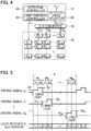
- FIG. 4 is a diagram showing a configuration of the detection device 100 with a focus on the functions of the control device 12.
- the control device 12 of the first embodiment serves as elements (a light emission controller 42, a detected value selector 44, and a detection controller 46) for controlling the movement detector 16 by executing the program stored in the storage device 14.
- the functions of the control device 12 may be distributed among multiple devices, or a part of the functions of the control device 12 may be realized by a dedicated electronic circuit.
- the light emission controller 42 causes each of the M light emitters E 1 to E M in the movement detector 16 to sequentially emit light.
- FIG. 5 is an explanatory diagram illustrating control of each light emitter E m by the light emission controller 42.
- the light emission controller 42 causes each of the M light emitters E 1 to E M to sequentially emit light in each light emission period PE m .
- the operation to cause each of the M light emitters E 1 to E M to sequentially emit light is repeated at a predetermined cycle (hereafter referred to as "detection cycle”) P.
- the time length of the detection cycle P is approximately one millisecond, and the time length of a light emission period PE m is approximately 80 microseconds ( ⁇ 1/M).
- the light emission controller 42 of the first embodiment provides a driving signal Z m to a light emitter E m in the m-th light emission period PE m among the M light emission periods PE 1 to PE M within each detection cycle P, thereby causing the light emitter E m to emit light.
- the driving signal Z m is a current signal that causes the light emitter E m to emit light.
- a light emission period PE m includes a unit period U1 and a unit period U2.
- the unit period U1 is a first half period of a light emission period PE m
- the unit period U2 is a second half period of the light emission period PE m .
- the light emission controller 42 of the first embodiment causes a light emission level of a light emitter E m to differ between the unit period U1 and the unit period U2 within each light emission period PE m .
- the light emission controller 42 causes a signal level (more specifically, an amount of current) of a driving signal Z m provided to a light emitter E m to differ between the unit period U1 and the unit period U2, thereby causing the light emission level of the light emitter E m to vary within the light emission period PE m .
- the signal level X1 m of the driving signal Z m in the unit period U1 is below the signal level X2 m of the driving signal Z m in the unit period U2. Accordingly, the light emission level of the light emitter E m increases in a stepwise manner within the light emission period PE m .
- the light emission level of the light emitter E m varies within each light emission period PE m . Consequently, a light reception level of each of the N light receivers R 1 to R N differs between the unit period U1 and the unit period U2 within each light emission period PE m .
- the A/D converter 18 generates a light reception level L by A/D-converting a detection signal Q n generated by each of the N light receivers R 1 to R N in each of the unit period U1 and the unit period U2 within each light emission period PE m .
- the light reception level L1 of a light receiver R n in the unit period U1 and the light reception level L2 of the light receiver R n in the unit period U2 are generated for each light emission period PE m for each of the N light receivers R 1 to R N .
- the detected value selector 44 of FIG. 4 selects a light reception level L in one of the unit period U1 and the unit period U2 within a light emission period PE m (that is, selects either the light reception level L1 in the unit period U1 or the light reception level L2 in the unit period U2) as a detected value d m,n , for each of the N light receivers R 1 to R n .
- a detected value d m,n is a light reception level L of a light receiver R n in a light emission period PE m in which a light emitter E m emits light
- the detected value d m,n corresponds to a numerical value that indicates a location (key press status) of a key 30 corresponding to a detector D m,n .
- the path length from a light emitter E m to a light receiver R n may differ between the N light receivers R 1 to R n .
- a surface condition of an end face of an optical fiber that forms the light emission path 162 or the light reception path 168 may differ for each of the N light receivers R 1 to R n .
- the light quantity of the detection light entering each light emission path 162 from a light emitter E m may differ depending on the location of the light emission path 162 relative to the light-emitting face.
- characteristics of a light receiver R n may differ for each light receiver R n due to manufacturing variability or aging.
- light reception levels L may differ between the N light receivers R 1 to R N .
- a signal level of a driving signal Z m provided to each light emitter E m differs between unit periods U (U1 and U2), and consequently, a light emission level of each light emitter E m varies within a light emission period PE m . Furthermore, for each light receiver R n , a light reception level L of the light receiver R n in one of the unit periods U within a light emission period PE m is selected as a detected value d m,n . In other words, one of the light reception levels L (L1 and L2) when a light emitter E m is caused to emit light at different light emission levels is selected as a detected value d m,n for each light receiver R n .
- the detection controller 46 of FIG. 4 controls the movement detection processing SB described above as an example. Specifically, the detection controller 46 sets, for each light emitter E m (i.e., for each light emission period PE m ), the signal level X1 m in the unit period U1 and the signal level X2 m in the unit period U2.
- the detection controller 46 of the first embodiment sets a combination of the signal level X1 m and the signal level X2 m for each light emitter E m , such that a light reception level L of each of the N light receivers R 1 to R N when a driving signal Z m at either the signal level X1 m or the signal level X2 m is provided to the light emitter E m is below a threshold value (upper limit) L TH .
- the detection controller 46 sets the signal level X1 m and the signal level X2 m from signal levels A selected in advance.
- the detection controller 46 of the first embodiment sets, for each combination of a light emitter E m and a light receiver R n (for each detector D m,n ), which of the light reception level L1 in the unit period U1 and the light reception level L2 in the unit period U2 should be selected (hereafter referred to as "selection target level") as a detected value d m,n by the detected value selector 44.
- FIG. 6 is a flowchart illustrating processing (hereafter referred to as "detection control processing") SA that sets the signal level X1 m and the signal level X2 m for each light emitter E m and sets a selection target level for each detector D m,n .
- the detection control processing SA of FIG. 6 is initiated with, for example, a start-up of the detection device 100 or an instruction from the user serving as a trigger, and after execution of the detection control processing SA, the movement detection processing SB is initiated.
- all the keys 30 are kept in a key release status. In other words, detection light emitted from each light emitter E m reaches each of the N light receivers R 1 to R N without being shielded by the corresponding light shield 32.
- the detection controller 46 selects one (hereafter referred to as "selected light emitter E m ”) of the M light emitters E 1 to E M (SA1). The detection controller 46 then sets a signal level A to an initial value, the signal level A being a candidate for a signal level X1 m and a signal level X2 m (SA2). The initial value of the signal level A is a smallest value among signal levels A selected in advance.
- the detection controller 46 causes the selected light emitter E m to emit light by providing a driving signal Z m at the signal level A of the current phase to the selected light emitter E m (SA3). Detection light emitted from the selected light emitter E m reaches each of the N light receivers R 1 to R N , and a light reception level L of each light receiver R n is output from the A/D converter 18. The detection controller 46 acquires from the A/D converter 18 the light reception level L of each of the N light receivers R 1 to R N (SA4).
- the light reception level L acquired by the detection controller 46 at step SA4 can be different for each light receiver R n .
- the detection controller 46 determines whether the light reception level L of any of the N light receivers R 1 to R N is above the threshold value L TH (i.e., determines whether there is an overflow) (SA5). In a case where the light reception levels L of all the N light receivers R 1 to R N are below the threshold value L TH (SA5:NO), the detection controller 46 increases the signal level A by one grade (SA6) and the processing proceeds to step SA3.
- the detection controller 46 sets the signal level X1 m and the signal level X2 m corresponding to the selected light emitter E m in accordance with the signal level A of the current phase (SA7). More specifically, the signal level X1 m in the unit period U1 is set to a signal level A that is one grade below the signal level A of the current phase, and the signal level X2 m in the unit period U2 is set to the signal level A of the current phase.
- the signal level X1 m and the signal level X2 m set in the above manner are stored in the storage device 14 for each light emitter E m .
- FIG. 7 is an explanatory diagram illustrating setting of the signal level X1 m and the signal level X2 m .
- FIG. 7 for each of cases (phase 1, phase 2, and phase 3) among which the signal level A is varied, there is illustrated a relationship between the light reception level L of each of the N light receivers R 1 to R N and the threshold value L TH .
- the signal level A2 in phase 2 is above the signal level A1 in phase 1
- the signal level A3 in phase 3 is above the signal level A2 in phase 2 (A1 ⁇ A2 ⁇ A3).
- phase 1 the light reception levels L of all the N light receivers R 1 to R N are below the threshold value L TH (SA5:NO), and thus, the processing proceeds to phase 2 in which the signal level A2 that is one grade above the signal level A1 is used.
- phase 2 the light reception levels L of all the N light receivers R 1 to R N are below the threshold value L TH (SA5:NO), and thus, the processing proceeds to phase 3 in which the signal level A3 that is one grade above the signal level A2 is used.
- phase 3 the light reception levels L of three light receivers R 1 to R 3 , among the N light receivers R 1 to R N , are above the threshold value L TH (SA5:YES). Accordingly, the signal level A2 in the preceding phase 2 is used as the signal level X1 m in the unit period U1, and the signal level A3 in phase 3 is used as the signal level X2 m in the unit period U2 (SA7).
- the detection controller 46 sets, for each combination of the selected light emitter E m and each of the N light receivers R 1 to R N , which of the light reception level L1 in the unit period U1 and the light reception level L2 in the unit period U2 (i.e., which of the unit period U1 and the unit period U2) should be selected when the movement detection processing SB is executed (SA8).
- the detection controller 46 of the first embodiment adopts from among the signal level X1 m and the signal level X2 m , as the selection target level in the movement detection processing SB, a signal level that results in the light reception level L of the light receiver R n being the largest of the two in a range below the threshold value L TH when a driving signal Z m at the subject signal level is provided to the selected light emitter E m .
- the processing at step SA8 in which either the signal level X1 m or the signal level X2 m is specified as the selection target level, can be expressed as processing that specifies either the unit period U1 or the unit period U2 as the selection target level, or as processing that specifies the light reception level L1 or the light reception level L2 as the selection target level.
- the selection target level set in the above manner is stored in the storage device 14 for each combination of a light emitter E m and a light receiver R n .
- the order of step SA7 and step SA8 may be reversed.
- the detection controller 46 determines whether the above processing (SA1 to SA8) is complete for all of the M light emitters E 1 to E M in the movement detector 16 (SA9). In a case where the determination result is negative (SA9:NO), the detection controller 46 selects an unprocessed light emitter E m from among the M light emitters E 1 to E M as the selected light emitter E m (SA1), and executes the subsequent processing (SA2 to SA9) for the updated selected light emitter E m . After the setting of the signal level X1 m and the signal level X2 m (SA7) and the setting of the selection target level (SA8) are complete for the M light emitters E 1 to E M (SA9:YES), the detection control processing SA of FIG. 6 comes to an end.
- FIG. 8 is a flowchart illustrating movement detection processing SB executed based on the result of the detection control processing SA described above as an example.
- the movement detection processing SB of FIG. 8 is executed for each of the M light emission periods PE 1 to PE M in each detection cycle P.
- the light emission controller 42 selects a light emitter E m (hereafter referred to as "driven light emitter E m ”) that corresponds to the light emission period PE m from among the M light emitters E 1 to E M (SB 1).
- the light emission controller 42 identifies the signal level X1 m and the signal level X2 m set in the detection control processing SA with respect to the driven light emitter E m (SB2). More specifically, the light emission controller 42 acquires the signal level X1 m and the signal level X2 m for the driven light emitter E m from the storage device 14.
- the light emission controller 42 Upon arrival of the unit period U1 of the light emission period PE m , the light emission controller 42 provides the driven light emitter E m with a driving signal Z m at the signal level X1 m identified at step SB2, thereby causing the driven light emitter E m to emit light (SB3).
- the A/D converter 18 identifies N light reception levels L1 by A/D-converting detection signals Q n output by the N light receivers R 1 to R N during light emission by the driven light emitter E m in the unit period U1.
- the detected value selector 44 acquires the N light reception levels L1 of the light receivers R n from the A/D converter 18 (SB4).
- the light emission controller 42 Upon arrival of the unit period U2 of the light emission period PE m , the light emission controller 42 provides the driven light emitter E m with a driving signal Z m at the signal level X2 m identified at step SB2 with respect to the unit period U2, thereby causing the driven light emitter E m to emit light (SB5).
- the A/D converter 18 identifies N light reception levels L2 by A/D-converting detection signals Q n output by the N light receivers R 1 to R N during light emission by the driven light emitter E m in the unit period U2.
- the detected value selector 44 acquires the N light reception levels L2 of the light receivers R n from the A/D converter 18 (SB6).
- the light reception level L1 in the unit period U1 and the light reception level L2 in the unit period U2 are measured for each of the N light receivers R 1 to R N .
- the detected value selector 44 selects, for each of the N light receivers R 1 to R N , either the light reception level L1 or the light reception level L2 as a detected value d m,n (SB7).
- the detected value selector 44 selects as the detected value d m,n the light reception level L in a unit period U, from among the unit period U1 and the unit period U2 in the light emission period PE m , in which unit period U there is provided to the driven light emitter E m a driving signal Z m at the signal level (X1 m , or X2 m ) specified as the selection target level in the detection control processing SA for a combination of the driven light emitter E m and a light receiver R n .
- the scenario shown in FIG. 7 can be assumed.
- a light reception level L is adopted that is achieved when there is provided to the light receiver R n a driving signal Z m at a signal level that is largest in a range where the resultant light reception level L of the light receiver R n is below the threshold value L TH .
- each detected values d m,n is in accordance with a status of each detector D m,n (movement of each key 30) corresponding to each combination of a light emitter E m and a light receiver R n .
- the control device 12 analyzes a time series of detected values d m,n of each key 30 (change in displacement of each key 30 over time) to generate performance data.
- a signal level in a range in which the light reception level L of a light receiver R n is below the threshold value L TH is set for each combination of a light emitter E m and a light receiver R n .
- a detected value d m,n a light reception level L of a light receiver R n in a unit period U in which there is provided to a light emitter E m a driving signal Z m at the signal level that has been set, the unit period U being among the unit period U1 and the unit period U2 within a light emission period PE m .
- FIG. 9 there is shown a waveform of a detection signal Q n output by a light receiver R n .
- a signal level e.g., amount of current
- a signal level of an actual detection signal Q n may change unsteadily.
- a signal level of a detection signal Q n may change unsteadily immediately after the light emission level of a light emitter E m changes at a start point t1 of a unit period U (U1 or U2).
- A/D conversion of a detection signal Q n (generation of a light reception level L) by the A/D converter 18 is executed in a period (hereafter referred to as "stable period") PS in which a signal level of a detection signal Q n is stable within each unit period U.
- the stable period PS is, for example, a period between a time point t2, at which a predetermined time length TA (e.g., approximately 18 microseconds) has passed since a start point t1 of each unit period U, and an end point t3 of the unit period U.
- a time length TB of the stable period PS is approximately 20 to 23 microseconds, for example.
- the A/D converter 18 generates a light reception level L by starting the A/D conversion of a detection signal Q n at the time point t2, which is delayed by the time length TA relative to the start point t1 of the unit period U.
- the A/D conversion is not executed in a period over the time length TA from the start point t1 to the time point t2 of each unit period U (i.e., a period in which the signal level of the detection signal Q n changes unsteadily).
- the detected value selector 44 of the second embodiment acquires light reception levels L (L1 and L2) within the stable periods PS in the unit periods U within the light emission period PE m . Operation of the detected value selector 44 to select either the light reception level L1 in the unit period U1 or the light reception level L2 in the unit period U2 as the detected value d m,n is similar to that described in the first embodiment.
- the detected value selector 44 acquires a light reception level L in a stable period PS in which the light reception level (the signal level of the detection signal Q n ) is stable within each unit period U. Accordingly, compared to a configuration in which the detected value selector 44 acquires a light reception level L in a period in which the signal level of the detection signal Q n changes unsteadily within each unit period U (e.g., a period from the start point t1 to the time point t2 of the unit period U), an advantageous effect is achieved in that accurate detected values d m,n can be generated, and consequently, movement of each key 30 can be accurately detected.
- the A/D conversion of a detection signal Q n by the A/D converter 18 may be started at the start point t1 of a unit period U, and the detected value selector 44 may select a light reception level L in a stable period PS from among light reception levels L generated in the unit period U.
- each light emission period PE m includes two unit periods U (U1 and U2).
- the total number K of unit periods U in the light emission period PE m is not limited to two.
- each light emission period PE m may include three or more unit periods U.
- FIG. 10 is a diagram showing a configuration of a detection device 100 of a third embodiment with a focus on the functions of the control device 12.
- the control device 12 of the third embodiment serves as the elements (the light emission controller 42, the detected value selector 44, and the detection controller 46) described in the first embodiment, and also serves as a period controller 48.
- the period controller 48 controls the total number K of unit periods U within each light emission period PE m and the time length T of each unit period U.
- the period controller 48 of the third embodiment controls the total number K of unit periods U within a light emission period PE m and the time length T of each unit period U in accordance with the time length TA from a start point of each unit period U to a time point t2 at which a signal level of a detection signal Q n becomes stable.
- the time length T of a unit period U is a sum of a time length TA, which is from the start point t1 to the time point t2 of the unit period U, and the time length TB of a stable period PS.
- the A/D converter 18 starts A/D conversion of a detection signal Q n at a time point t2 within the unit period U (at the start point of the stable period PS).
- the period controller 48 causes a light emitter E m to emit light by providing a driving signal Z m and analyzes detection signals Q n generated by the light receivers R n upon emission of light by the light emitter E m , thereby measuring a time length TA (e.g., the maximum value among the N detection signals Q 1 to Q N ) from a start of light emission by the light emitter E m to a time point at which the signal levels of detection signals Q n become stable.
- the period controller 48 sets the time length T of a unit period U to the sum of the time length TA and a predetermined time length TB.
- the time length TB of a stable period PS is fixed to a time length required by the A/D converter 18 to generate a light reception level L, for example. Accordingly, the total time length T of a unit period U is a length that may vary depending on the time length TA.
- the period controller 48 sets the total number K of unit periods U within a light emission period PE m in accordance with the time length T of the unit period U determined in the above manner. More specifically, the period controller 48 sets the total number K to the maximum number of unit periods U (time length T) that can be included in a light emission period PE m of a predetermined length. Thus, the shorter is a time length TA required for a signal level of a detection signal Q n to become stable, the greater is a total number K of unit periods U within a light emission period PE m .
- a time length of a light emission period PE m and a time length of a detection cycle P are each fixed to a predetermined value.
- the detection controller 46 of the third embodiment sets signal levels (X1 m to XK m ) for each light emitter E m . More specifically, the detection controller 46 sets the signal levels X1 m to XK m such that the light reception level L of each of the N light receivers R 1 to R n when a driving signal Z m at one of the signal levels X1 m to XK m is provided to a light emitter E m , is below the threshold value L TH .
- the detection controller 46 sets, the light reception level L of which unit period U, among the K unit periods U1 to UK within a light emission period PE m , is to be selected as the detected value d m,n (selection target level) for each combination of a light emitter E m and a light receiver R n .
- the detected value selector 44 selects as the detected value d m,n a light reception level Lk in a unit period Uk corresponding to the signal level Xk m set as the selection target level in the detection control processing SA, the unit period Uk being among the K unit periods U1 to UK (SB7).
- the total number K of unit periods U within each light emission period PE m and the time length T of each unit period U are changed in accordance with a time length TA required for stabilization of a signal level of a detection signal Q n . Accordingly, as is described in the above example, by a configuration in which the total number K of unit periods U increases as the time length TA becomes shorter, it is possible to accurately compensate for variabilities in light reception levels L for each light receiver R n , and consequently, to accurately detect movement of each key 30.
- the relative strength of signal levels of a driving signal Z m in unit periods U within a light emission period PE m may be freely chosen.
- the signal level X1 m in the unit period U1 is below the signal level X2 m in the unit period U2.
- the signal level X1 m may be above the signal level X2 m (i.e., the light emission level of a light emitter E m may decrease stepwise within a light emission period PE m ).
- the signal level A of a driving signal Z m is increased stepwise from an initial value.
- provision of the driving signal Z m to the selected light emitter E m (SA3) and acquisition of a light reception level L of each light receiver R n (SA4) may be executed while the signal level A of a driving signal Z m is decreased stepwise from the maximum value.
- the detection controller 46 determines whether the light reception level L of any one of the N light receiver R 1 to R N is below the threshold value L TH .
- the signal level X1 m or the signal level X2 m that has been set in the past detection control processing SA may be used as an initial value (SA2) of the signal level A in the detection control processing SA.
- a combination of a signal level X1 m and a signal level X2 m is set for each light emitter E m such that the light reception level L is below the threshold value L TH when a driving signal Z m at either the signal level X1 m or the signal level X2 m is provided to the light emitter E m .
- This configuration may be modified.
- a combination of a signal level X1 m and a signal level X2 m may be set for each light emitter E m such that the light reception level L is above the threshold value (lower limit) L TH when a driving signal Z m at either the signal level X1 m or the signal level X2 m is provided to the light emitter E m .
- the detection controller 46 is comprehensively described as an element that sets, for each combination of a light emitter E m and a light receiver R n , signal levels that keep the light reception levels L of the N light receivers R 1 to R N within a predetermined range (a range below an upper limit or a range above a lower limit) when a driving signal Z m is provided to the light emitter E m .
- an exemplary detection device 100 that detects movement of each key 30 of the keyboard instrument 200 is described.
- an object to be detected by the detection device 100 is not limited to a key 30.
- the detection device 100 similar to that described in each of the above embodiments may be used for detection of movement of each of hammers that strike strings in the keyboard instrument 200, or may be used for detection of movement of each of operating elements (e.g., buttons or tabs) operated freely by the user.
- an object to be detected by the detection device 100 can be comprehensively described as a movable moving body.
- the detection device 100 described as an example in each of the above embodiments is realized by coordination between the control device 12 and the program.
- a program according to a preferred mode of the present invention causes a computer that is capable of controlling a movement detector 16 to serve as a light emission controller 42 and a detected value selector 44.
- the movement detector 16 includes M light emitters E 1 to E M and N light receivers R 1 to R N , wherein in accordance with movement of a moving body among moving bodies (e.g., keys 30), each moving body corresponding to a different combination of a light emitter E m and a light receiver R n , the light reception level L of the light receiver R n in the combination corresponding to the moving body changes.
- the light emission controller 42 causes each of the M light emitters E 1 to E M to sequentially emit light in each light emission period PE m by providing a driving signal Z m , and to cause a signal level of the driving signal Z m to differ between unit periods U within the light emission period PE m .
- the detected value selector 44 selects, for each light emission period PE m , a light reception level L in one of the unit periods U within the light emission period PE m as a detected value d m,n for each of the N light receivers R 1 to R N .
- the exemplary program described above may be stored in a computer-readable recording medium and be provided for installation in the computer.
- the recording medium may be a non-transitory recording medium; a good example of which is an optical recording medium (optical disk), such as a CD-ROM.
- the recording medium can encompass any publicly known format, such as a semiconductor recording medium or a magnetic recording medium.
- non-transitory recording medium here includes all computer-readable recording medium except for a transitory, propagating signal; however, a volatile recording medium is not excluded.
- the program can be delivered to the computer by distribution via a communication network.
- the program can be distributed to the computer by distribution via a communication network.
- a preferred mode of the present invention may be understood as an operation method (detection method) in the detection device 100 in each of the embodiments described above as examples.
- a detection method (movement detection processing SB) according to a preferred mode of the present invention is implemented in a computer that is capable of controlling a movement detector 16 that includes M light emitters E 1 to E M and N light receivers R 1 to R N , wherein in accordance with movement of a moving body among moving bodies (e.g., keys 30), each moving body corresponding to a different combination of a light emitter E m and a light receiver R n , a light reception level L of the light receiver R n in the combination corresponding to the moving body changes.
- the detection method includes: causing each of the M light emitters E 1 to E M to sequentially emit light in each light emission period PE m by providing a driving signal Z m , and causing a signal level of the driving signal Z m to differ between unit periods U within the light emission period PE m ; and selecting, for each light emission period PE m , a light reception level L in one of the unit periods U within the light emission period PE m as a detected value d m,n for each of the N light receivers R 1 to R N .
- a detection device includes: a movement detector configured to include light emitters and light receivers, wherein in accordance with movement of a moving body among moving bodies, each moving body corresponding to a different combination of one of the light emitters and one of the light receivers, a light reception level of the light receiver in a combination corresponding to the moving body changes; a light emission controller configured to cause each of the light emitters to sequentially emit light in each light emission period by providing a driving signal, and to cause a signal level of the driving signal to differ between unit periods within the light emission period; and a detected value selector configured to select, for each light emission period, a light reception level in one of the unit periods within the light emission period as a detected value for each of the light receivers.
- the signal level (e.g., current value) of a driving signal provided to each light emitter is caused to differ between unit periods, thereby causing a light emission level of each light emitter to vary in a light emission period.
- a light reception level of each light receiver in one of the unit periods within the light emission period is selected as a detected value for each light receiver. Accordingly, it is possible to compensate for variabilities in the light reception levels between the light receivers, and consequently, to accurately detect movement of moving bodies.
- the detection device according to a preferred mode (mode 2) of mode 1 further includes a detection controller configured to, for each combination of one of the light emitters and one of the light receivers, set signal levels such that a light reception level of the light receiver when a driving signal is provided to the light emitter falls within a predetermined range, wherein the light emission controller causes each light emitter to emit light at one of the signal levels in each unit period within the light emission period, and wherein the detected value selector selects, as the detected value, a light reception level of the light receiver in a unit period in which there is provided to the light emitter a driving signal at one of the signal levels set by the detection controller with respect to the combination of the light emitter and the light receiver, the unit period being among the unit periods within the light emission period.
- a detection controller configured to, for each combination of one of the light emitters and one of the light receivers, set signal levels such that a light reception level of the light receiver when a driving signal is provided to the light emitter falls within a predetermined range
- signal levels are set for each combination of a light emitter and a light receiver such that a light reception level of the light receiver falls within a predetermined range (e.g., signal levels at which the light reception level is below a threshold value).
- a predetermined range e.g., signal levels at which the light reception level is below a threshold value.
- the detected value selector acquires a light reception level in a stable period within each of the unit periods in the light emission period, the stable period being a period in which the light reception level is stable, and selects a light reception level in one of the unit periods as the detected value.
- the detected value selector acquires a light reception level in a stable period in which the light reception level is stable, the stable period being within a unit period.
- the detected value selector acquires a light reception level in a period in which the light reception level changes unsteadily (e.g., a period immediately after a start point of a unit period), it is possible to generate an accurate detected value, and consequently, to accurately detect movement of each moving body.
- the detection device according to a preferred mode (mode 4) of mode 3 further includes a period controller configured to control a total number of unit periods within the light emission period and a time length of each unit period in accordance with a time length from a start point of the unit period to a time point at which the light reception level becomes stable.
- a period controller configured to control a total number of unit periods within the light emission period and a time length of each unit period in accordance with a time length from a start point of the unit period to a time point at which the light reception level becomes stable.
- a total number of unit periods in a light emission period and a time length of each unit period are controlled. Accordingly, by increasing the total number of unit periods by shortening the time length of each unit period as the time length required for the light reception level to stabilize decreases, it is possible to accurately compensate for variabilities in light reception levels among light receivers.
- the moving body is a key of a keyboard instrument.
- this mode it is possible to accurately detect movement of each key of a keyboard instrument.
- a keyboard instrument includes: keys; and a detection device configured to detect movement of each of the keys.
- the detection device includes: a movement detector configured to include light emitters and light receivers, wherein each of the keys corresponds to a different combination of one of the light emitters and one of the light receivers, and wherein in accordance with movement of a key among the keys, a light reception level of the light receiver in a combination corresponding to the key changes; a light emission controller configured to cause each of the light emitters to sequentially emit light in each light emission period by providing a driving signal, and to cause a signal level of the driving signal to differ between unit periods within the light emission period; and a detected value selector configured to select, for each light emission period, a light reception level in one of the unit periods within the light emission period as a detected value for each of the light receivers.
- a program according to a preferred mode (mode 7) of the present invention causes a computer that controls a movement detector to execute light-emission control processing and detected-value selection processing.
- the movement detector includes light emitters and light receivers, wherein in accordance with movement of a moving body among moving bodies, each moving body corresponding to a different combination of each light emitter and each light receiver, a light reception level of the light receiver in a combination corresponding to the moving body changes.
- the light-emission control processing causes each of the light emitters to sequentially emit light in each light emission period by providing a driving signal, and causes a signal level of the driving signal to differ between unit periods within the light emission period; and the detected-value selection processing selects, for each light emission period, a light reception level in one of the unit periods within the light emission period as a detected value for each of the light receivers.
- a detection method is implemented in a computer that controls a movement detector configured to include light emitters and light receivers, wherein in accordance with movement of a moving body among moving bodies, each moving body corresponding to a different combination of each light emitter and each light receiver, a light reception level of the light receiver in a combination corresponding to the moving body changes.
- the computer causes each of the light emitters to sequentially emit light in each light emission period by providing a driving signal, and causes a signal level of the driving signal to differ between unit periods within the light emission period; and selects, for each light emission period, a light reception level in one of the unit periods within the light emission period as a detected value for each of the light receivers.
Landscapes
- Engineering & Computer Science (AREA)
- Physics & Mathematics (AREA)
- General Engineering & Computer Science (AREA)
- Theoretical Computer Science (AREA)
- Acoustics & Sound (AREA)
- Multimedia (AREA)
- General Physics & Mathematics (AREA)
- Human Computer Interaction (AREA)
- Electrophonic Musical Instruments (AREA)
- Geophysics And Detection Of Objects (AREA)
- Circuit Arrangement For Electric Light Sources In General (AREA)
Abstract
Description
- The present invention relates to a technique for detecting movement of moving bodies, such as keys of a keyboard instrument.
- In a detection device for optically detecting movement of moving bodies such as keys of a keyboard instrument, there is a problem that variabilities exist in characteristics of light receiving elements or light emitting elements due to manufacturing variability or aging.
Patent Document 1 discloses a technique in which, in a configuration where movement of operating elements is detected by combinations of light emitters and light receivers, a light emission level of each light emitter and a light reception level of each light receiver are adjusted. In the technique disclosed inPatent Document 1, the light emission level of each light emitter is determined such that no output signal from the light receivers exceeds a predetermined threshold value, and a largest light reception signal that is below the threshold value under a particular light emission level is selected as an output signal from among light reception signals derived by dividing a voltage that accords with a light reception level of a light receiver. - Patent Document 1: Japanese Patent Application Laid-Open Publication No.
2005-195794 - Even if a light emission level is adjusted to a particular value for each light emitter, as in the technique disclosed in
Patent Document 1, variabilities in light reception levels of light receivers when a light emitter emits light are not compensated. With a view to reducing variabilities in the light reception levels of light receivers, in the technique disclosed in Patent Document 1 a configuration is used to select one of light reception signals generated in parallel in accordance with the light reception level of each light receiver. However, in the above configuration, it is necessary to use a voltage-dividing circuit (an array of resistive elements) for generating light reception signals by dividing a voltage that accords with the light reception level of a light receiver; and also to use an integrated circuit (multiplexer) for sequentially selecting a light reception signal from the light reception signals for each emission of light by a light emitter. As a result, the configuration of the device is made complex. Taking into account the circumstances discussed above, it is an object of the present invention to accurately detect movement of moving bodies while preventing the configuration of the device from becoming overly complex. - To solve the above problem, a detection device according to a preferred mode of the present invention includes: a movement detector configured to include light emitters and light receivers, wherein in accordance with movement of a moving body among moving bodies, each moving body corresponding to a different combination of one of the light emitters and one of the light receivers, a light reception level of the light receiver in a combination corresponding to the moving body changes; a light emission controller configured to cause each of the light emitters to sequentially emit light in each light emission period by providing a driving signal, and to cause a signal level of the driving signal to differ between unit periods within the light emission period; and a detected value selector configured to select, for each light emission period, a light reception level in one of the unit periods within the light emission period as a detected value for each of the light receivers.
- A keyboard instrument according to a preferred mode of the present invention includes: keys; and a detection device configured to detect movement of each of the keys, wherein the detection device includes: a movement detector configured to include light emitters and light receivers, wherein each of the keys corresponds to a different combination of one of the light emitters and one of the light receivers, and wherein in accordance with movement of a key among the keys, a light reception level of a light receiver in a combination corresponding to the key changes; a light emission controller configured to cause each of the light emitters to sequentially emit light in each light emission period by providing a driving signal, and to cause a signal level of the driving signal to differ between unit periods within the light emission period; and a detected value selector configured to select, for each light emission period, a light reception level in one of the unit periods within the light emission period as a detected value for each of the light receivers.
- A program according to a preferred mode of the present invention causes a computer that controls a movement detector to execute light-emission control processing and detected-value selection processing, wherein the movement detector includes light emitters and light receivers, wherein in accordance with movement of a moving body among moving bodies, each moving body corresponding to a different combination of one of the light emitters and one of the light receivers, a light reception level of the light receiver in a combination corresponding to the moving body changes, wherein the light-emission control processing causes each of the light emitters to sequentially emit light in each light emission period by providing a driving signal, and causes a signal level of the driving signal to differ between unit periods within the light emission period; and wherein the detected-value selection processing selects, for each light emission period, a light reception level in one of the unit periods within the light emission period as a detected value for each of the light receivers.
- A detection method according to a preferred mode of the present invention is implemented in a computer that controls a movement detector configured to include light emitters and light receivers, wherein in accordance with movement of a moving body among moving bodies, each moving body corresponding to a different combination of one of the light emitters and one of the light receivers, a light reception level of a light receiver in a combination corresponding to the moving body changes, the detection method including: causing each of the light emitters to sequentially emit light in each light emission period by providing a driving signal, and causing a signal level of the driving signal to differ between unit periods within the light emission period; and selecting, for each light emission period, a light reception level in one of the unit periods within the light emission period as a detected value for each of the light receivers.
-
-
FIG. 1 is a diagram showing a configuration of a keyboard instrument in a first embodiment of the present invention. -
FIG. 2 is a diagram showing a configuration of a detection device in the first embodiment of the present invention. -
FIG. 3 is a schematic diagram of a detector. -
FIG. 4 is a diagram showing a configuration of the detection device with a focus on functions of a control device. -
FIG. 5 is an explanatory diagram illustrating operations of a light emission controller. -
FIG. 6 is a flowchart illustrating detection control processing. -
FIG. 7 is an explanatory diagram illustrating signal level setting performed in the detection control processing. -
FIG. 8 is a flowchart illustrating movement detection processing. -
FIG. 9 is an explanatory diagram illustrating generation of a light reception level in a second embodiment. -
FIG. 10 is a diagram showing a configuration of a detection device in a third embodiment. -
FIG. 1 is a diagram showing a configuration of akeyboard instrument 200 according to a first embodiment of the present invention. As shown in the example inFIG. 1 , thekeyboard instrument 200 in the first embodiment includes akeyboard 210 and adetection device 100. Thekeyboard 210 is configured to include multiple keys 30 (e.g., 88 keys) including white keys and black keys. -
FIG. 2 is a diagram showing a configuration of thedetection device 100 according to the first embodiment of the present invention. Thedetection device 100 of the first embodiment is a sensor that is used in thekeyboard instrument 200 to optically detect movement of each of thekeys 30. As shown in the example inFIG. 2 , thedetection device 100 of the first embodiment includes acontrol device 12, astorage device 14, amovement detector 16, an A/D converter 18, asound source circuit 20, and asound output device 22. - The
control device 12 is realized by use of processing circuitry, such as a CPU (central processing unit) or an FPGA (field-programmable gate array), and centrally controls each element in thedetection device 100. Thestorage device 14 stores a program executed by thecontrol device 12 together with various data used by thecontrol device 12. A publicly known recording medium, such as a semiconductor recording medium or a magnetic recording medium, or a combination of various types of recording media may be used as thestorage device 14. - The
movement detector 16 detects movement of eachkey 30 of the keyboard instrument 200 (specifically, displacement of eachkey 30 when pressed by a player), and includes multiple (M) light emitters E1 to EM and multiple (N) light receivers R1 to RN (M and N are each a natural number equal to or greater than two). A light emitter Em (m = 1 to M) is configured to include a light emitting element, such as a LED (light emitting diode), and emits light (hereafter referred to as "detection light") by being provided with a driving signal Zm. A light receiver Rn (n = 1 to N) is configured to include a light receiving element, such as a photodiode, and generates a detection signal Qn that accords with a light reception level. - The M light emitters E1 to EM and the N light receivers R1 to RN form a sensor matrix of M rows and N columns (e.g., 12 rows × 8 columns). A detector Dm,n is disposed in correspondence with a combination of a light emitter Em and a light receiver Rn. Each detector Dm,n corresponds to a
different key 30 of thekeyboard 210. A correspondence relationship between each detector Dm,n and eachkey 30 may be freely determined. For illustrative purposes, inFIG. 2 , a detector Dm,n is illustrated for every combination of a light emitter Em and a light receiver Rn. In reality, however, a combination may exist for which a detector Dm,n is not disposed. -
FIG. 3 is a schematic diagram showing a freely-chosen exemplary detector Dm,n. As shown in the example ofFIG. 3 , a detector Dm,n is a sensor head that includes alight emission path 162, alight guide 164, alight guide 166, alight reception path 168, and alight shield 32. Thelight emission path 162 and thelight reception path 168 are each a path through which detection light propagates, and are each configured to include an optical fiber, for example. Detection light emitted from a light emitter Em propagates through thelight emission path 162 to reach thelight guide 164, and exits to the side of thelight guide 166 by being reflected inside thelight guide 164. The detection light that enters thelight guide 166 from thelight guide 164 then enters thelight reception path 168 by being reflected inside thelight guide 166, and propagates through thelight reception path 168 to reach a light receiver Rn. Alight shield 32 is, for example, a light-shielding shutter that is fixed to the bottom of eachkey 30 of thekeyboard instrument 200. Thelight shield 32 moves to a space between thelight guide 164 and thelight guide 166 upon pressing of the corresponding key by a user. Accordingly, a light reception level by each light receiver Rn (a signal level of a detection signal Qn) changes depending on a location (i.e., a key press status) of eachkey 30. - The detection light emitted from an m-th light emitter Em is provided to each of the
light emission paths 162 of the N detectors Dm,1 to Dm,N corresponding to the m-th row in themovement detector 16. The detection light that has passed through thelight reception paths 168 of the M detectors D1,n to DM,n corresponding to an n-th column in themovement detector 16 is received by the n-th light receiver Rn. Thus, by detecting a light reception level of each of the N light receivers R1 to RN at the time of emission of light by a freely chosen light emitter Em, it is possible to detect movement of each key 30 (a status of each detector Dm,n) corresponding to a combination of the light emitter Em and each light receiver Rn. As is disclosed in Japanese Patent Application Laid-Open Publication No.H09-152871 - The A/
D converter 18 ofFIG. 2 converts an analog detection signal Qn generated by each of the N light receivers R1 to RN into digital data (hereafter referred to as "light reception level") L. Thecontrol device 12 analyzes a status of eachkey 30 from a time series of light reception levels L, which have undergone conversion by the A/D converter 18. In accordance with a result of analyzing the light reception levels L, thecontrol device 12 generates performance data that specify a time series of status (emitted or muted) and intensity of sound corresponding to eachkey 30. The performance data are stored in thestorage device 14. In other words, performance on thekeyboard instrument 200 by the user is recorded. Thesound source circuit 20 ofFIG. 2 generates an audio signal of performance sound specified by the performance data. The audio signal generated by thesound source circuit 20 is provided to the sound output device 22 (speaker or headphones), thereby causing the performance sound specified by the performance data to be played. Here, a drive mechanism (e.g., solenoid) may drive eachkey 30 in accordance with the performance data, thereby realizing automatic playing of thekeyboard instrument 200. The functions of thesound source circuit 20 may be realized by thecontrol device 12. -
FIG. 4 is a diagram showing a configuration of thedetection device 100 with a focus on the functions of thecontrol device 12. As shown in the example ofFIG. 4 , thecontrol device 12 of the first embodiment serves as elements (alight emission controller 42, a detectedvalue selector 44, and a detection controller 46) for controlling themovement detector 16 by executing the program stored in thestorage device 14. Alternatively, the functions of thecontrol device 12 may be distributed among multiple devices, or a part of the functions of thecontrol device 12 may be realized by a dedicated electronic circuit. - The
light emission controller 42 causes each of the M light emitters E1 to EM in themovement detector 16 to sequentially emit light.FIG. 5 is an explanatory diagram illustrating control of each light emitter Em by thelight emission controller 42. As shown in the example ofFIG. 5 , in processing (hereafter referred to as "movement detection processing") SB for detecting movement of each key 30 of thekeyboard instrument 200, thelight emission controller 42 causes each of the M light emitters E1 to EM to sequentially emit light in each light emission period PEm. The operation to cause each of the M light emitters E1 to EM to sequentially emit light is repeated at a predetermined cycle (hereafter referred to as "detection cycle") P. The time length of the detection cycle P is approximately one millisecond, and the time length of a light emission period PEm is approximately 80 microseconds (≈ 1/M). Thelight emission controller 42 of the first embodiment provides a driving signal Zm to a light emitter Em in the m-th light emission period PEm among the M light emission periods PE1 to PEM within each detection cycle P, thereby causing the light emitter Em to emit light. The driving signal Zm is a current signal that causes the light emitter Em to emit light. - As shown in
FIG. 5 , a light emission period PEm includes a unit period U1 and a unit period U2. For example, the unit period U1 is a first half period of a light emission period PEm, and the unit period U2 is a second half period of the light emission period PEm. Thelight emission controller 42 of the first embodiment causes a light emission level of a light emitter Em to differ between the unit period U1 and the unit period U2 within each light emission period PEm. Specifically, thelight emission controller 42 causes a signal level (more specifically, an amount of current) of a driving signal Zm provided to a light emitter Em to differ between the unit period U1 and the unit period U2, thereby causing the light emission level of the light emitter Em to vary within the light emission period PEm. As shown in the example ofFIG. 5 , the signal level X1m of the driving signal Zm in the unit period U1 is below the signal level X2m of the driving signal Zm in the unit period U2. Accordingly, the light emission level of the light emitter Em increases in a stepwise manner within the light emission period PEm. - As shown in the above example, in the first embodiment, the light emission level of the light emitter Em varies within each light emission period PEm. Consequently, a light reception level of each of the N light receivers R1 to RN differs between the unit period U1 and the unit period U2 within each light emission period PEm. The A/
D converter 18 generates a light reception level L by A/D-converting a detection signal Qn generated by each of the N light receivers R1 to RN in each of the unit period U1 and the unit period U2 within each light emission period PEm. In other words, the light reception level L1 of a light receiver Rn in the unit period U1 and the light reception level L2 of the light receiver Rn in the unit period U2 are generated for each light emission period PEm for each of the N light receivers R1 to RN. - The detected
value selector 44 ofFIG. 4 selects a light reception level L in one of the unit period U1 and the unit period U2 within a light emission period PEm (that is, selects either the light reception level L1 in the unit period U1 or the light reception level L2 in the unit period U2) as a detected value dm,n, for each of the N light receivers R1 to Rn. Since a detected value dm,n is a light reception level L of a light receiver Rn in a light emission period PEm in which a light emitter Em emits light, the detected value dm,n corresponds to a numerical value that indicates a location (key press status) of a key 30 corresponding to a detector Dm,n. - The path length from a light emitter Em to a light receiver Rn (light loss in the
light emission path 162 and the light reception path 168) may differ between the N light receivers R1 to Rn. A surface condition of an end face of an optical fiber that forms thelight emission path 162 or thelight reception path 168 may differ for each of the N light receivers R1 to Rn. In a configuration using light emitters Em in each of which the intensity of detection light varies within the plane of a light-emitting face, the light quantity of the detection light entering eachlight emission path 162 from a light emitter Em may differ depending on the location of thelight emission path 162 relative to the light-emitting face. It is possible that characteristics of a light receiver Rn (e.g., a relationship between an amount of received light and a signal level of a detection signal Qn) may differ for each light receiver Rn due to manufacturing variability or aging. As a result of various differences described above as examples, when a freely chosen light emitter Em is caused to emit light, light reception levels L may differ between the N light receivers R1 to RN. - In the first embodiment, a signal level of a driving signal Zm provided to each light emitter Em differs between unit periods U (U1 and U2), and consequently, a light emission level of each light emitter Em varies within a light emission period PEm. Furthermore, for each light receiver Rn, a light reception level L of the light receiver Rn in one of the unit periods U within a light emission period PEm is selected as a detected value dm,n. In other words, one of the light reception levels L (L1 and L2) when a light emitter Em is caused to emit light at different light emission levels is selected as a detected value dm,n for each light receiver Rn. Accordingly, it is possible to compensate for variabilities in light reception levels L among light receivers Rn (and consequently, to accurately detect movement of each key 30). Additionally, in principle, there is no need for a voltage-dividing circuit (an array of resistive elements) that generates light reception signals by dividing a voltage that accords with a light reception level L of each light receiver Rn; or for an integrated circuit (multiplexer) for sequentially selecting a light reception signal from among light reception signals for each emission of light by a light emitter. Accordingly, compared to the technique disclosed in
Patent Document 1, it is possible to reduce complexity of the configuration of a device. As described above, by the first embodiment, there is achieved an advantageous effect in that movement of each key 30 can be accurately detected while preventing the device configuration from becoming overly complex. - The
detection controller 46 ofFIG. 4 controls the movement detection processing SB described above as an example. Specifically, thedetection controller 46 sets, for each light emitter Em (i.e., for each light emission period PEm), the signal level X1m in the unit period U1 and the signal level X2m in the unit period U2. Thedetection controller 46 of the first embodiment sets a combination of the signal level X1m and the signal level X2m for each light emitter Em, such that a light reception level L of each of the N light receivers R1 to RN when a driving signal Zm at either the signal level X1m or the signal level X2m is provided to the light emitter Em is below a threshold value (upper limit) LTH. Thedetection controller 46 sets the signal level X1m and the signal level X2m from signal levels A selected in advance. Additionally, thedetection controller 46 of the first embodiment sets, for each combination of a light emitter Em and a light receiver Rn (for each detector Dm,n), which of the light reception level L1 in the unit period U1 and the light reception level L2 in the unit period U2 should be selected (hereafter referred to as "selection target level") as a detected value dm,n by the detectedvalue selector 44. -
FIG. 6 is a flowchart illustrating processing (hereafter referred to as "detection control processing") SA that sets the signal level X1m and the signal level X2m for each light emitter Em and sets a selection target level for each detector Dm,n. The detection control processing SA ofFIG. 6 is initiated with, for example, a start-up of thedetection device 100 or an instruction from the user serving as a trigger, and after execution of the detection control processing SA, the movement detection processing SB is initiated. During execution of the detection control processing SA, all thekeys 30 are kept in a key release status. In other words, detection light emitted from each light emitter Em reaches each of the N light receivers R1 to RN without being shielded by the correspondinglight shield 32. - After initiating the detection control processing SA, the
detection controller 46 selects one (hereafter referred to as "selected light emitter Em") of the M light emitters E1 to EM (SA1). Thedetection controller 46 then sets a signal level A to an initial value, the signal level A being a candidate for a signal level X1m and a signal level X2m (SA2). The initial value of the signal level A is a smallest value among signal levels A selected in advance. - The
detection controller 46 causes the selected light emitter Em to emit light by providing a driving signal Zm at the signal level A of the current phase to the selected light emitter Em (SA3). Detection light emitted from the selected light emitter Em reaches each of the N light receivers R1 to RN, and a light reception level L of each light receiver Rn is output from the A/D converter 18. Thedetection controller 46 acquires from the A/D converter 18 the light reception level L of each of the N light receivers R1 to RN (SA4). Since variabilities may exist in characteristics of each light receiver Rn (e.g., a relationship between the light quantity actually reaching the light receiver Rn and the light reception level L, which is a measured value), for example, the light reception level L acquired by thedetection controller 46 at step SA4 can be different for each light receiver Rn. - The
detection controller 46 determines whether the light reception level L of any of the N light receivers R1 to RN is above the threshold value LTH (i.e., determines whether there is an overflow) (SA5). In a case where the light reception levels L of all the N light receivers R1 to RN are below the threshold value LTH (SA5:NO), thedetection controller 46 increases the signal level A by one grade (SA6) and the processing proceeds to step SA3. In other words, until a light reception level L of any one of the N light receivers R1 to RN exceeds the threshold value LTH (SA5: YES), provision of a driving signal Zm to the selected light emitter Em (SA3) and acquisition of the light reception level L of each light receiver Rn (SA4) are repeated in each case where the signal level A is increased from the initial value in a stepwise manner. - In a case where the light reception level L of any one of the N light receivers R1 to RN is above the threshold value LTH (SA5: YES), the
detection controller 46 sets the signal level X1m and the signal level X2m corresponding to the selected light emitter Em in accordance with the signal level A of the current phase (SA7). More specifically, the signal level X1m in the unit period U1 is set to a signal level A that is one grade below the signal level A of the current phase, and the signal level X2m in the unit period U2 is set to the signal level A of the current phase. The signal level X1m and the signal level X2m set in the above manner are stored in thestorage device 14 for each light emitter Em. -
FIG. 7 is an explanatory diagram illustrating setting of the signal level X1m and the signal level X2m. InFIG. 7 , for each of cases (phase 1,phase 2, and phase 3) among which the signal level A is varied, there is illustrated a relationship between the light reception level L of each of the N light receivers R1 to RN and the threshold value LTH. The signal level A2 inphase 2 is above the signal level A1 inphase 1, and the signal level A3 inphase 3 is above the signal level A2 in phase 2 (A1 < A2 < A3). - In
phase 1, the light reception levels L of all the N light receivers R1 to RN are below the threshold value LTH (SA5:NO), and thus, the processing proceeds tophase 2 in which the signal level A2 that is one grade above the signal level A1 is used. Similarly, inphase 2, the light reception levels L of all the N light receivers R1 to RN are below the threshold value LTH (SA5:NO), and thus, the processing proceeds tophase 3 in which the signal level A3 that is one grade above the signal level A2 is used. Inphase 3, the light reception levels L of three light receivers R1 to R3, among the N light receivers R1 to RN, are above the threshold value LTH (SA5:YES). Accordingly, the signal level A2 in thepreceding phase 2 is used as the signal level X1m in the unit period U1, and the signal level A3 inphase 3 is used as the signal level X2m in the unit period U2 (SA7). - After setting the signal level X1m and the signal level X2m corresponding to the selected light emitter Em in the above manner, the
detection controller 46 sets, for each combination of the selected light emitter Em and each of the N light receivers R1 to RN, which of the light reception level L1 in the unit period U1 and the light reception level L2 in the unit period U2 (i.e., which of the unit period U1 and the unit period U2) should be selected when the movement detection processing SB is executed (SA8). More specifically, thedetection controller 46 of the first embodiment adopts from among the signal level X1m and the signal level X2m, as the selection target level in the movement detection processing SB, a signal level that results in the light reception level L of the light receiver Rn being the largest of the two in a range below the threshold value LTH when a driving signal Zm at the subject signal level is provided to the selected light emitter Em. For example, in the scenario shown inFIG. 7 as an example, the signal level X1m (= A2) is specified as the selection target level for the light receivers R1 to R3, and the signal level X2m (= A3) is specified as the selection target level for the rest of the light receivers R4 to RN. - Selection of the signal level X1m refers to selection of the light reception level L1 in the unit period U1, and selection of the signal level X2m refers to selection of the light reception level L2 in the unit period U2. Accordingly, the processing at step SA8, in which either the signal level X1m or the signal level X2m is specified as the selection target level, can be expressed as processing that specifies either the unit period U1 or the unit period U2 as the selection target level, or as processing that specifies the light reception level L1 or the light reception level L2 as the selection target level. The selection target level set in the above manner is stored in the
storage device 14 for each combination of a light emitter Em and a light receiver Rn. The order of step SA7 and step SA8 may be reversed. - The
detection controller 46 determines whether the above processing (SA1 to SA8) is complete for all of the M light emitters E1 to EM in the movement detector 16 (SA9). In a case where the determination result is negative (SA9:NO), thedetection controller 46 selects an unprocessed light emitter Em from among the M light emitters E1 to EM as the selected light emitter Em (SA1), and executes the subsequent processing (SA2 to SA9) for the updated selected light emitter Em. After the setting of the signal level X1m and the signal level X2m (SA7) and the setting of the selection target level (SA8) are complete for the M light emitters E1 to EM (SA9:YES), the detection control processing SA ofFIG. 6 comes to an end. -
FIG. 8 is a flowchart illustrating movement detection processing SB executed based on the result of the detection control processing SA described above as an example. With completion of the detection control processing SA or an instruction from the user serving as a trigger, the movement detection processing SB ofFIG. 8 is executed for each of the M light emission periods PE1 to PEM in each detection cycle P. After initiating the movement detection processing SB for a light emission period PEM, thelight emission controller 42 selects a light emitter Em (hereafter referred to as "driven light emitter Em") that corresponds to the light emission period PEm from among the M light emitters E1 to EM (SB 1). - The
light emission controller 42 identifies the signal level X1m and the signal level X2m set in the detection control processing SA with respect to the driven light emitter Em (SB2). More specifically, thelight emission controller 42 acquires the signal level X1m and the signal level X2m for the driven light emitter Em from thestorage device 14. - Upon arrival of the unit period U1 of the light emission period PEm, the
light emission controller 42 provides the driven light emitter Em with a driving signal Zm at the signal level X1m identified at step SB2, thereby causing the driven light emitter Em to emit light (SB3). The A/D converter 18 identifies N light reception levels L1 by A/D-converting detection signals Qn output by the N light receivers R1 to RN during light emission by the driven light emitter Em in the unit period U1. The detectedvalue selector 44 acquires the N light reception levels L1 of the light receivers Rn from the A/D converter 18 (SB4). - Upon arrival of the unit period U2 of the light emission period PEm, the
light emission controller 42 provides the driven light emitter Em with a driving signal Zm at the signal level X2m identified at step SB2 with respect to the unit period U2, thereby causing the driven light emitter Em to emit light (SB5). The A/D converter 18 identifies N light reception levels L2 by A/D-converting detection signals Qn output by the N light receivers R1 to RN during light emission by the driven light emitter Em in the unit period U2. The detectedvalue selector 44 acquires the N light reception levels L2 of the light receivers Rn from the A/D converter 18 (SB6). - As described in the above example, the light reception level L1 in the unit period U1 and the light reception level L2 in the unit period U2 are measured for each of the N light receivers R1 to RN. The detected
value selector 44 selects, for each of the N light receivers R1 to RN, either the light reception level L1 or the light reception level L2 as a detected value dm,n (SB7). More specifically, the detectedvalue selector 44 selects as the detected value dm,n the light reception level L in a unit period U, from among the unit period U1 and the unit period U2 in the light emission period PEm, in which unit period U there is provided to the driven light emitter Em a driving signal Zm at the signal level (X1m, or X2m) specified as the selection target level in the detection control processing SA for a combination of the driven light emitter Em and a light receiver Rn. For example, the scenario shown inFIG. 7 can be assumed. For each of the light receivers R1 to R3, there is selected as the detected value dm,n the light reception level L1 acquired in the unit period U1 in which the driving signal Zm is set to the signal level X1m (= A2). For each of the rest of the light receivers R4 to RN, there is selected as the detected value dm,n the light reception level L2 acquired in the unit period U2 in which the driving signal Zm is set to the signal level X2m (= A3). In other words, as the detected value dm,n of each light receiver Rn, a light reception level L is adopted that is achieved when there is provided to the light receiver Rn a driving signal Zm at a signal level that is largest in a range where the resultant light reception level L of the light receiver Rn is below the threshold value LTH. - By repeating the movement detection processing SB described above for each light emission period PEm, there are sequentially generated detected values dm,n in each detection cycle P, wherein each detected values dm,n is in accordance with a status of each detector Dm,n (movement of each key 30) corresponding to each combination of a light emitter Em and a light receiver Rn. The
control device 12 analyzes a time series of detected values dm,n of each key 30 (change in displacement of each key 30 over time) to generate performance data. - As described above, in the first embodiment, a signal level in a range in which the light reception level L of a light receiver Rn is below the threshold value LTH, is set for each combination of a light emitter Em and a light receiver Rn. There is selected as a detected value dm,n a light reception level L of a light receiver Rn in a unit period U in which there is provided to a light emitter Em a driving signal Zm at the signal level that has been set, the unit period U being among the unit period U1 and the unit period U2 within a light emission period PEm. Thus, an advantageous effect is achieved in that detected values dm,n that are within an appropriate range below the threshold value LTH can be generated.
- A second embodiment of the present invention will now be described. In each embodiment described below by way of example, elements with operations or functions similar to those in the first embodiment are denoted by the same reference signs as those used in the first embodiment, and detailed explanations of such elements are omitted, as appropriate.
- In
FIG. 9 there is shown a waveform of a detection signal Qn output by a light receiver Rn. Due to a transient response caused by capacity components accompanying the light receiver Rn, for example, a signal level (e.g., amount of current) of an actual detection signal Qn may change unsteadily. For example, as shown inFIG. 9 , a signal level of a detection signal Qn may change unsteadily immediately after the light emission level of a light emitter Em changes at a start point t1 of a unit period U (U1 or U2). - In view of the above circumstances, in the second embodiment, A/D conversion of a detection signal Qn (generation of a light reception level L) by the A/
D converter 18 is executed in a period (hereafter referred to as "stable period") PS in which a signal level of a detection signal Qn is stable within each unit period U. The stable period PS is, for example, a period between a time point t2, at which a predetermined time length TA (e.g., approximately 18 microseconds) has passed since a start point t1 of each unit period U, and an end point t3 of the unit period U. A time length TB of the stable period PS is approximately 20 to 23 microseconds, for example. The A/D converter 18 generates a light reception level L by starting the A/D conversion of a detection signal Qn at the time point t2, which is delayed by the time length TA relative to the start point t1 of the unit period U. The A/D conversion is not executed in a period over the time length TA from the start point t1 to the time point t2 of each unit period U (i.e., a period in which the signal level of the detection signal Qn changes unsteadily). - The detected
value selector 44 of the second embodiment acquires light reception levels L (L1 and L2) within the stable periods PS in the unit periods U within the light emission period PEm. Operation of the detectedvalue selector 44 to select either the light reception level L1 in the unit period U1 or the light reception level L2 in the unit period U2 as the detected value dm,n is similar to that described in the first embodiment. - The second embodiment achieves advantageous effects similar to those achieved in the first embodiment. Furthermore, in the second embodiment, the detected
value selector 44 acquires a light reception level L in a stable period PS in which the light reception level (the signal level of the detection signal Qn) is stable within each unit period U. Accordingly, compared to a configuration in which the detectedvalue selector 44 acquires a light reception level L in a period in which the signal level of the detection signal Qn changes unsteadily within each unit period U (e.g., a period from the start point t1 to the time point t2 of the unit period U), an advantageous effect is achieved in that accurate detected values dm,n can be generated, and consequently, movement of each key 30 can be accurately detected. - Alternatively, the A/D conversion of a detection signal Qn by the A/
D converter 18 may be started at the start point t1 of a unit period U, and the detectedvalue selector 44 may select a light reception level L in a stable period PS from among light reception levels L generated in the unit period U. - In the first embodiment and the second embodiment, examples are given in which each light emission period PEm includes two unit periods U (U1 and U2). However, the total number K of unit periods U in the light emission period PEm is not limited to two. In other words, each light emission period PEm may include three or more unit periods U.
-
FIG. 10 is a diagram showing a configuration of adetection device 100 of a third embodiment with a focus on the functions of thecontrol device 12. As shown in the example ofFIG. 10 , thecontrol device 12 of the third embodiment serves as the elements (thelight emission controller 42, the detectedvalue selector 44, and the detection controller 46) described in the first embodiment, and also serves as aperiod controller 48. Theperiod controller 48 controls the total number K of unit periods U within each light emission period PEm and the time length T of each unit period U. More specifically, theperiod controller 48 of the third embodiment controls the total number K of unit periods U within a light emission period PEm and the time length T of each unit period U in accordance with the time length TA from a start point of each unit period U to a time point t2 at which a signal level of a detection signal Qn becomes stable. The time length T of a unit period U is a sum of a time length TA, which is from the start point t1 to the time point t2 of the unit period U, and the time length TB of a stable period PS. Similarly to the second embodiment, the A/D converter 18 starts A/D conversion of a detection signal Qn at a time point t2 within the unit period U (at the start point of the stable period PS). - More specifically, in the detection control processing SA, the
period controller 48 causes a light emitter Em to emit light by providing a driving signal Zm and analyzes detection signals Qn generated by the light receivers Rn upon emission of light by the light emitter Em, thereby measuring a time length TA (e.g., the maximum value among the N detection signals Q1 to QN) from a start of light emission by the light emitter Em to a time point at which the signal levels of detection signals Qn become stable. Theperiod controller 48 then sets the time length T of a unit period U to the sum of the time length TA and a predetermined time length TB. The time length TB of a stable period PS is fixed to a time length required by the A/D converter 18 to generate a light reception level L, for example. Accordingly, the total time length T of a unit period U is a length that may vary depending on the time length TA. - Additionally, the
period controller 48 sets the total number K of unit periods U within a light emission period PEm in accordance with the time length T of the unit period U determined in the above manner. More specifically, theperiod controller 48 sets the total number K to the maximum number of unit periods U (time length T) that can be included in a light emission period PEm of a predetermined length. Thus, the shorter is a time length TA required for a signal level of a detection signal Qn to become stable, the greater is a total number K of unit periods U within a light emission period PEm. A time length of a light emission period PEm and a time length of a detection cycle P are each fixed to a predetermined value. - In the detection control processing SA, for the total of K unit periods U1 to UK, wherein the total number K has been set by the
period controller 48, thedetection controller 46 of the third embodiment sets signal levels (X1m to XKm) for each light emitter Em. More specifically, thedetection controller 46 sets the signal levels X1m to XKm such that the light reception level L of each of the N light receivers R1 to Rn when a driving signal Zm at one of the signal levels X1m to XKm is provided to a light emitter Em, is below the threshold value LTH. Moreover, thedetection controller 46 sets, the light reception level L of which unit period U, among the K unit periods U1 to UK within a light emission period PEm, is to be selected as the detected value dm,n (selection target level) for each combination of a light emitter Em and a light receiver Rn. - In the movement detection processing SB, the
light emission controller 42 causes a light emitter Em to emit light by providing a driving signal Zm at a signal level Xkm (k = 1 to K) in each of the K unit periods U1 to UK within each light emission period PEm (SB3 and SB5). For each light emission period PEm, the detectedvalue selector 44 selects as the detected value dm,n a light reception level Lk in a unit period Uk corresponding to the signal level Xkm set as the selection target level in the detection control processing SA, the unit period Uk being among the K unit periods U1 to UK (SB7). - In the third embodiment, advantageous effects are achieved similar to those achieved in each of the first embodiment and the second embodiment. Moreover, in the third embodiment, the total number K of unit periods U within each light emission period PEm and the time length T of each unit period U are changed in accordance with a time length TA required for stabilization of a signal level of a detection signal Qn. Accordingly, as is described in the above example, by a configuration in which the total number K of unit periods U increases as the time length TA becomes shorter, it is possible to accurately compensate for variabilities in light reception levels L for each light receiver Rn, and consequently, to accurately detect movement of each key 30.
- A variety of modifications can be made to each of the embodiment described above. Exemplary modifications are described below. Two or more modes freely selected from the examples below may be combined as appropriate.
- (1) The relative strength of signal levels of a driving signal Zm in unit periods U within a light emission period PEm may be freely chosen. For example, in each embodiment described above, an exemplary configuration is described in which the signal level X1m in the unit period U1 is below the signal level X2m in the unit period U2. However, the signal level X1m may be above the signal level X2m (i.e., the light emission level of a light emitter Em may decrease stepwise within a light emission period PEm).
- (2) In the detection control processing SA in each embodiment described above, the signal level A of a driving signal Zm is increased stepwise from an initial value. Alternatively, provision of the driving signal Zm to the selected light emitter Em (SA3) and acquisition of a light reception level L of each light receiver Rn (SA4) may be executed while the signal level A of a driving signal Zm is decreased stepwise from the maximum value. In a case where the signal level A is gradually decreased, the
detection controller 46 determines whether the light reception level L of any one of the N light receiver R1 to RN is below the threshold value LTH. Alternatively or additionally, the signal level X1m or the signal level X2m that has been set in the past detection control processing SA (typically, the preceding detection control processing SA) may be used as an initial value (SA2) of the signal level A in the detection control processing SA. - (3) In the first embodiment, a combination of a signal level X1m and a signal level X2m is set for each light emitter Em such that the light reception level L is below the threshold value LTH when a driving signal Zm at either the signal level X1m or the signal level X2m is provided to the light emitter Em. This configuration may be modified. For example, a combination of a signal level X1m and a signal level X2m may be set for each light emitter Em such that the light reception level L is above the threshold value (lower limit) LTH when a driving signal Zm at either the signal level X1m or the signal level X2m is provided to the light emitter Em. As will be apparent from the above examples, the
detection controller 46 is comprehensively described as an element that sets, for each combination of a light emitter Em and a light receiver Rn, signal levels that keep the light reception levels L of the N light receivers R1 to RN within a predetermined range (a range below an upper limit or a range above a lower limit) when a driving signal Zm is provided to the light emitter Em. - (4) In each embodiment described above, an
exemplary detection device 100 that detects movement of each key 30 of thekeyboard instrument 200 is described. However, an object to be detected by thedetection device 100 is not limited to a key 30. For example, thedetection device 100 similar to that described in each of the above embodiments may be used for detection of movement of each of hammers that strike strings in thekeyboard instrument 200, or may be used for detection of movement of each of operating elements (e.g., buttons or tabs) operated freely by the user. As will be apparent from the above examples, an object to be detected by thedetection device 100 can be comprehensively described as a movable moving body. - (5) As already stated, the
detection device 100 described as an example in each of the above embodiments is realized by coordination between thecontrol device 12 and the program. A program according to a preferred mode of the present invention causes a computer that is capable of controlling amovement detector 16 to serve as alight emission controller 42 and a detectedvalue selector 44. Themovement detector 16 includes M light emitters E1 to EM and N light receivers R1 to RN, wherein in accordance with movement of a moving body among moving bodies (e.g., keys 30), each moving body corresponding to a different combination of a light emitter Em and a light receiver Rn, the light reception level L of the light receiver Rn in the combination corresponding to the moving body changes. Thelight emission controller 42 causes each of the M light emitters E1 to EM to sequentially emit light in each light emission period PEm by providing a driving signal Zm, and to cause a signal level of the driving signal Zm to differ between unit periods U within the light emission period PEm. The detectedvalue selector 44 selects, for each light emission period PEm, a light reception level L in one of the unit periods U within the light emission period PEm as a detected value dm,n for each of the N light receivers R1 to RN. The exemplary program described above may be stored in a computer-readable recording medium and be provided for installation in the computer. For example, the recording medium may be a non-transitory recording medium; a good example of which is an optical recording medium (optical disk), such as a CD-ROM. However, the recording medium can encompass any publicly known format, such as a semiconductor recording medium or a magnetic recording medium. The term "non-transitory recording medium" here includes all computer-readable recording medium except for a transitory, propagating signal; however, a volatile recording medium is not excluded. The program can be delivered to the computer by distribution via a communication network. The program can be distributed to the computer by distribution via a communication network. - (6) A preferred mode of the present invention may be understood as an operation method (detection method) in the
detection device 100 in each of the embodiments described above as examples. A detection method (movement detection processing SB) according to a preferred mode of the present invention is implemented in a computer that is capable of controlling amovement detector 16 that includes M light emitters E1 to EM and N light receivers R1 to RN, wherein in accordance with movement of a moving body among moving bodies (e.g., keys 30), each moving body corresponding to a different combination of a light emitter Em and a light receiver Rn, a light reception level L of the light receiver Rn in the combination corresponding to the moving body changes. The detection method includes: causing each of the M light emitters E1 to EM to sequentially emit light in each light emission period PEm by providing a driving signal Zm, and causing a signal level of the driving signal Zm to differ between unit periods U within the light emission period PEm; and selecting, for each light emission period PEm, a light reception level L in one of the unit periods U within the light emission period PEm as a detected value dm,n for each of the N light receivers R1 to RN. - (7) From the above embodiments and modifications described as examples, the following configurations, for example, can be understood.
- A detection device according to a preferred mode (mode 1) of the present invention includes: a movement detector configured to include light emitters and light receivers, wherein in accordance with movement of a moving body among moving bodies, each moving body corresponding to a different combination of one of the light emitters and one of the light receivers, a light reception level of the light receiver in a combination corresponding to the moving body changes; a light emission controller configured to cause each of the light emitters to sequentially emit light in each light emission period by providing a driving signal, and to cause a signal level of the driving signal to differ between unit periods within the light emission period; and a detected value selector configured to select, for each light emission period, a light reception level in one of the unit periods within the light emission period as a detected value for each of the light receivers. In the above configuration, the signal level (e.g., current value) of a driving signal provided to each light emitter is caused to differ between unit periods, thereby causing a light emission level of each light emitter to vary in a light emission period. A light reception level of each light receiver in one of the unit periods within the light emission period is selected as a detected value for each light receiver. Accordingly, it is possible to compensate for variabilities in the light reception levels between the light receivers, and consequently, to accurately detect movement of moving bodies. Furthermore, in principle it is not necessary to use a voltage-dividing circuit (an array of resistive elements) that generates light reception signals by dividing a voltage that accords with a light reception level of each light receiver; or to use an integrated circuit (multiplexer) for sequentially selecting a light reception signal from light reception signals for each emission of light by a light emitter. Thus, compared to the technique disclosed in
Patent Document 1, it is possible to reduce the complexity of the device configuration. - The detection device according to a preferred mode (mode 2) of
mode 1 further includes a detection controller configured to, for each combination of one of the light emitters and one of the light receivers, set signal levels such that a light reception level of the light receiver when a driving signal is provided to the light emitter falls within a predetermined range, wherein the light emission controller causes each light emitter to emit light at one of the signal levels in each unit period within the light emission period, and wherein the detected value selector selects, as the detected value, a light reception level of the light receiver in a unit period in which there is provided to the light emitter a driving signal at one of the signal levels set by the detection controller with respect to the combination of the light emitter and the light receiver, the unit period being among the unit periods within the light emission period. In this mode, signal levels are set for each combination of a light emitter and a light receiver such that a light reception level of the light receiver falls within a predetermined range (e.g., signal levels at which the light reception level is below a threshold value). A light reception level of a light receiver in a unit period, among unit periods within a light emission period, in which period a driving signal at one of the signal levels is provided to the light emitter, is selected as a detected value. Accordingly, it is possible to generate a detected value that is within an appropriate range. - In a preferred mode (mode 3) of
mode - The detection device according to a preferred mode (mode 4) of
mode 3 further includes a period controller configured to control a total number of unit periods within the light emission period and a time length of each unit period in accordance with a time length from a start point of the unit period to a time point at which the light reception level becomes stable. In this mode, in accordance with a time length from a start point of a unit period to a time point at which a light reception level becomes stable, a total number of unit periods in a light emission period and a time length of each unit period are controlled. Accordingly, by increasing the total number of unit periods by shortening the time length of each unit period as the time length required for the light reception level to stabilize decreases, it is possible to accurately compensate for variabilities in light reception levels among light receivers. - In a preferred mode (mode 5) of any one of
modes 1 to 4, the moving body is a key of a keyboard instrument. In this mode, it is possible to accurately detect movement of each key of a keyboard instrument. - A keyboard instrument according to a preferred mode (mode 6) of the present invention includes: keys; and a detection device configured to detect movement of each of the keys. The detection device includes: a movement detector configured to include light emitters and light receivers, wherein each of the keys corresponds to a different combination of one of the light emitters and one of the light receivers, and wherein in accordance with movement of a key among the keys, a light reception level of the light receiver in a combination corresponding to the key changes; a light emission controller configured to cause each of the light emitters to sequentially emit light in each light emission period by providing a driving signal, and to cause a signal level of the driving signal to differ between unit periods within the light emission period; and a detected value selector configured to select, for each light emission period, a light reception level in one of the unit periods within the light emission period as a detected value for each of the light receivers.
- A program according to a preferred mode (mode 7) of the present invention causes a computer that controls a movement detector to execute light-emission control processing and detected-value selection processing. The movement detector includes light emitters and light receivers, wherein in accordance with movement of a moving body among moving bodies, each moving body corresponding to a different combination of each light emitter and each light receiver, a light reception level of the light receiver in a combination corresponding to the moving body changes. The light-emission control processing causes each of the light emitters to sequentially emit light in each light emission period by providing a driving signal, and causes a signal level of the driving signal to differ between unit periods within the light emission period; and the detected-value selection processing selects, for each light emission period, a light reception level in one of the unit periods within the light emission period as a detected value for each of the light receivers.
- A detection method according to a preferred mode (mode 8) of the present invention is implemented in a computer that controls a movement detector configured to include light emitters and light receivers, wherein in accordance with movement of a moving body among moving bodies, each moving body corresponding to a different combination of each light emitter and each light receiver, a light reception level of the light receiver in a combination corresponding to the moving body changes. The computer causes each of the light emitters to sequentially emit light in each light emission period by providing a driving signal, and causes a signal level of the driving signal to differ between unit periods within the light emission period; and selects, for each light emission period, a light reception level in one of the unit periods within the light emission period as a detected value for each of the light receivers.
- 100...detection device; 12...control device; 14... storage device; 16...movement detector; 162...light emission path; 164...light guide; 166...light guide; 168...light reception path; 18...A/D converter; 20...sound source circuit; 22...sound output device; 30...key (moving body); 32...light shield; 42...light emission controller; 44... detected value selector; 46... detection controller; 48... period controller; 200...keyboard instrument; 210...keyboard.
Claims (8)
- A detection device comprising:a movement detector configured to include light emitters and light receivers, wherein in accordance with movement of a moving body among moving bodies, each moving body corresponding to a different combination of one of the light emitters and one of the light receivers, a light reception level of the light receiver in a combination corresponding to the moving body changes;a light emission controller configured to cause each of the light emitters to sequentially emit light in each light emission period by providing a driving signal, and to cause a signal level of the driving signal to differ between unit periods within the light emission period; anda detected value selector configured to select, for each light emission period, a light reception level in one of the unit periods within the light emission period as a detected value for each of the light receivers.
- The detection device according to claim 1, further comprising a detection controller configured to, for each combination of one of the light emitters and one of the light receivers, set signal levels such that a light reception level of the light receiver when a driving signal is provided to the light emitter falls within a predetermined range,
wherein the light emission controller causes each light emitter to emit light at one of the signal levels in each unit period within the light emission period, and
wherein the detected value selector selects, as the detected value, a light reception level of the light receiver in a unit period in which there is provided to the light emitter a driving signal at one of the signal levels set by the detection controller with respect to the combination of the light emitter and the light receiver, the unit period being among the unit periods within the light emission period. - The detection device according to claim 1 or 2,
wherein the detected value selector acquires a light reception level in a stable period within each of the unit periods in the light emission period, the stable period being a period in which the light reception level is stable, and selects a light reception level in one of the unit periods as the detected value. - The detection device according to claim 3, further comprising a period controller configured to control a total number of unit periods within the light emission period and a time length of each unit period in accordance with a time length from a start point of the unit period to a time point at which the light reception level becomes stable.
- The detection device according to any one of claims 1 to 4,
wherein the moving body is a key of a keyboard instrument. - A keyboard instrument comprising:keys; anda detection device configured to detect movement of each of the keys,wherein the detection device comprises:a movement detector configured to include light emitters and light receivers, wherein each of the keys corresponds to a different combination of one of the light emitters and one of the light receivers, and wherein in accordance with movement of a key among the keys, a light reception level of a light receiver in a combination corresponding to the key changes;a light emission controller configured to cause each of the light emitters to sequentially emit light in each light emission period by providing a driving signal, and to cause a signal level of the driving signal to differ between unit periods within the light emission period; anda detected value selector configured to select, for each light emission period, a light reception level in one of the unit periods within the light emission period as a detected value for each of the light receivers.
- A program causing a computer that controls a movement detector to execute light-emission control processing and detected-value selection processing,
wherein the movement detector includes light emitters and light receivers,
wherein in accordance with movement of a moving body among moving bodies, each moving body corresponding to a different combination of one of the light emitters and one of the light receivers, a light reception level of the light receiver in a combination corresponding to the moving body changes,
wherein the light-emission control processing causes each of the light emitters to sequentially emit light in each light emission period by providing a driving signal, and causes a signal level of the driving signal to differ between unit periods within the light emission period; and
wherein the detected-value selection processing selects, for each light emission period, a light reception level in one of the unit periods within the light emission period as a detected value for each of the light receivers. - A detection method implemented in a computer that controls a movement detector configured to include light emitters and light receivers, wherein in accordance with movement of a moving body among moving bodies, each moving body corresponding to a different combination of one of the light emitters and one of the light receivers, a light reception level of the light receiver in a combination corresponding to the moving body changes,
the detection method comprising:causing each of the light emitters to sequentially emit light in each light emission period by providing a driving signal, and causing a signal level of the driving signal to differ between unit periods within the light emission period; andselecting, for each light emission period, a light reception level in one of the unit periods within the light emission period as a detected value for each of the light receivers.
Applications Claiming Priority (2)
| Application Number | Priority Date | Filing Date | Title |
|---|---|---|---|
| JP2016038804A JP6524940B2 (en) | 2016-03-01 | 2016-03-01 | Detection device and program |
| PCT/JP2017/005258 WO2017150171A1 (en) | 2016-03-01 | 2017-02-14 | Detection device, keyboard musical instrument, detection method, and program |
Publications (3)
| Publication Number | Publication Date |
|---|---|
| EP3425625A1 true EP3425625A1 (en) | 2019-01-09 |
| EP3425625A4 EP3425625A4 (en) | 2019-10-02 |
| EP3425625B1 EP3425625B1 (en) | 2020-11-04 |
Family
ID=59742796
Family Applications (1)
| Application Number | Title | Priority Date | Filing Date |
|---|---|---|---|
| EP17759642.6A Active EP3425625B1 (en) | 2016-03-01 | 2017-02-14 | Detection device, keyboard musical instrument, detection method, and program |
Country Status (5)
| Country | Link |
|---|---|
| US (1) | US10782159B2 (en) |
| EP (1) | EP3425625B1 (en) |
| JP (1) | JP6524940B2 (en) |
| CN (1) | CN108604442B (en) |
| WO (1) | WO2017150171A1 (en) |
Families Citing this family (3)
| Publication number | Priority date | Publication date | Assignee | Title |
|---|---|---|---|---|
| JP7396014B2 (en) * | 2019-12-13 | 2023-12-12 | ヤマハ株式会社 | Setting device and controls |
| JP7568082B2 (en) * | 2021-05-19 | 2024-10-16 | ヤマハ株式会社 | Musical instruments, keyboard mechanisms and pedal mechanisms |
| JP7586308B2 (en) * | 2021-05-19 | 2024-11-19 | ヤマハ株式会社 | musical instrument |
Family Cites Families (11)
| Publication number | Priority date | Publication date | Assignee | Title |
|---|---|---|---|---|
| JP3552374B2 (en) | 1995-11-30 | 2004-08-11 | ヤマハ株式会社 | Signal output device and optical sensor |
| JPH11296756A (en) * | 1998-04-14 | 1999-10-29 | Nippon Aleph:Kk | Detector |
| JP4129798B2 (en) | 2004-01-06 | 2008-08-06 | ヤマハ株式会社 | Optical detector |
| JP5209287B2 (en) * | 2007-12-13 | 2013-06-12 | ローランド株式会社 | Electronic musical instrument operation position detection device |
| US20090282962A1 (en) * | 2008-05-13 | 2009-11-19 | Steinway Musical Instruments, Inc. | Piano With Key Movement Detection System |
| GB2462081A (en) * | 2008-07-21 | 2010-01-27 | Eigenlabs Ltd | A programmable sound creation interface |
| JP2010122936A (en) * | 2008-11-20 | 2010-06-03 | Seiko Epson Corp | Sensing circuit, display and electronic apparatus |
| JP5423542B2 (en) * | 2010-04-02 | 2014-02-19 | セイコーエプソン株式会社 | Optical position detector |
| JP5516145B2 (en) * | 2010-06-30 | 2014-06-11 | セイコーエプソン株式会社 | Optical detection device, display device, and electronic apparatus |
| CN204577083U (en) * | 2015-04-21 | 2015-08-19 | 杭州随身教育科技有限公司 | Piano white-black key sensing state |
| US10634813B2 (en) * | 2015-05-18 | 2020-04-28 | Lasermotive, Inc. | Multi-layered safety system |
-
2016
- 2016-03-01 JP JP2016038804A patent/JP6524940B2/en active Active
-
2017
- 2017-02-14 WO PCT/JP2017/005258 patent/WO2017150171A1/en not_active Ceased
- 2017-02-14 EP EP17759642.6A patent/EP3425625B1/en active Active
- 2017-02-14 CN CN201780010504.3A patent/CN108604442B/en active Active
-
2018
- 2018-08-29 US US16/116,183 patent/US10782159B2/en active Active
Also Published As
| Publication number | Publication date |
|---|---|
| CN108604442B (en) | 2023-01-10 |
| CN108604442A (en) | 2018-09-28 |
| US20190011293A1 (en) | 2019-01-10 |
| EP3425625B1 (en) | 2020-11-04 |
| WO2017150171A1 (en) | 2017-09-08 |
| JP2017156496A (en) | 2017-09-07 |
| US10782159B2 (en) | 2020-09-22 |
| JP6524940B2 (en) | 2019-06-05 |
| EP3425625A4 (en) | 2019-10-02 |
Similar Documents
| Publication | Publication Date | Title |
|---|---|---|
| US10657943B2 (en) | Systems and methods for calibrating a musical device | |
| EP3425625B1 (en) | Detection device, keyboard musical instrument, detection method, and program | |
| US9099062B2 (en) | Keyboard musical instrument, method of controlling actuator in the keyboard musical instrument, and non-transitory recording medium storing program for controlling the actuator | |
| JP2011217068A (en) | Sound field controller | |
| US9799313B2 (en) | Electronic musical instrument, storage medium and note selecting method | |
| US7411124B2 (en) | Self-calibrating transducer system and musical instrument equipped with the same | |
| US20220270581A1 (en) | Detection system, musical instrument playing apparatus, and method | |
| US9502014B1 (en) | Actuator control in automatic performance of musical instrument | |
| US8933309B2 (en) | Simulating muting in a drive control device for striking member in sound generation mechanism | |
| US9343051B2 (en) | Performance information output control apparatus, keyboard instrument and control method thereof | |
| JP2005195794A (en) | Optical detecting apparatus | |
| US9905209B2 (en) | Electronic keyboard musical instrument | |
| JP6665580B2 (en) | Detection device and program | |
| JP2015084584A (en) | Sound field control device | |
| US20140305286A1 (en) | Keyboard musical instrument, and method for reproducing half performance of pedal or key damper on keyboard musical instrument | |
| JP2014206576A (en) | Half pedal area specifying method and device for keyboard instrument and program | |
| JP6728771B2 (en) | Detection device and program | |
| JP2013150158A (en) | Photoelectric switch and sensitivity adjustment method | |
| JP6357772B2 (en) | Electronic musical instrument, program and pronunciation pitch selection method | |
| US20140305285A1 (en) | Keyboard musical instrument, and method for recording half performance of pedal or key damper on keyboard musical instrument | |
| JP2009294021A (en) | Fluorescence temperature sensor | |
| JPH06149233A (en) | Method for adjusting key displacement detecting device of keyboard musical instrument | |
| US7469196B2 (en) | Measuring a characteristic of a transfer circuit | |
| JPH08137466A (en) | Key press detection device | |
| JP6343911B2 (en) | Electronic musical instrument, program and pronunciation pitch selection method |
Legal Events
| Date | Code | Title | Description |
|---|---|---|---|
| STAA | Information on the status of an ep patent application or granted ep patent |
Free format text: STATUS: THE INTERNATIONAL PUBLICATION HAS BEEN MADE |
|
| PUAI | Public reference made under article 153(3) epc to a published international application that has entered the european phase |
Free format text: ORIGINAL CODE: 0009012 |
|
| STAA | Information on the status of an ep patent application or granted ep patent |
Free format text: STATUS: REQUEST FOR EXAMINATION WAS MADE |
|
| 17P | Request for examination filed |
Effective date: 20180914 |
|
| AK | Designated contracting states |
Kind code of ref document: A1 Designated state(s): AL AT BE BG CH CY CZ DE DK EE ES FI FR GB GR HR HU IE IS IT LI LT LU LV MC MK MT NL NO PL PT RO RS SE SI SK SM TR |
|
| AX | Request for extension of the european patent |
Extension state: BA ME |
|
| DAV | Request for validation of the european patent (deleted) | ||
| DAX | Request for extension of the european patent (deleted) | ||
| A4 | Supplementary search report drawn up and despatched |
Effective date: 20190830 |
|
| RIC1 | Information provided on ipc code assigned before grant |
Ipc: G06F 3/03 20060101ALI20190826BHEP Ipc: G01D 5/34 20060101ALI20190826BHEP Ipc: G10H 1/34 20060101ALI20190826BHEP Ipc: G10H 1/00 20060101ALI20190826BHEP Ipc: G10H 1/18 20060101AFI20190826BHEP |
|
| REG | Reference to a national code |
Ref country code: DE Ref legal event code: R079 Ref document number: 602017026905 Country of ref document: DE Free format text: PREVIOUS MAIN CLASS: G10H0001180000 Ipc: G06F0003020000 |
|
| RIC1 | Information provided on ipc code assigned before grant |
Ipc: G10H 1/18 20060101ALI20200311BHEP Ipc: G06F 3/03 20060101ALI20200311BHEP Ipc: G10H 1/34 20060101ALI20200311BHEP Ipc: G10H 1/055 20060101ALI20200311BHEP Ipc: G06F 3/02 20060101AFI20200311BHEP |
|
| GRAP | Despatch of communication of intention to grant a patent |
Free format text: ORIGINAL CODE: EPIDOSNIGR1 |
|
| STAA | Information on the status of an ep patent application or granted ep patent |
Free format text: STATUS: GRANT OF PATENT IS INTENDED |
|
| INTG | Intention to grant announced |
Effective date: 20200527 |
|
| GRAS | Grant fee paid |
Free format text: ORIGINAL CODE: EPIDOSNIGR3 |
|
| GRAA | (expected) grant |
Free format text: ORIGINAL CODE: 0009210 |
|
| STAA | Information on the status of an ep patent application or granted ep patent |
Free format text: STATUS: THE PATENT HAS BEEN GRANTED |
|
| AK | Designated contracting states |
Kind code of ref document: B1 Designated state(s): AL AT BE BG CH CY CZ DE DK EE ES FI FR GB GR HR HU IE IS IT LI LT LU LV MC MK MT NL NO PL PT RO RS SE SI SK SM TR |
|
| REG | Reference to a national code |
Ref country code: GB Ref legal event code: FG4D |
|
| REG | Reference to a national code |
Ref country code: CH Ref legal event code: EP |
|
| REG | Reference to a national code |
Ref country code: AT Ref legal event code: REF Ref document number: 1331649 Country of ref document: AT Kind code of ref document: T Effective date: 20201115 |
|
| REG | Reference to a national code |
Ref country code: DE Ref legal event code: R096 Ref document number: 602017026905 Country of ref document: DE |
|
| REG | Reference to a national code |
Ref country code: IE Ref legal event code: FG4D |
|
| REG | Reference to a national code |
Ref country code: NL Ref legal event code: MP Effective date: 20201104 |
|
| REG | Reference to a national code |
Ref country code: AT Ref legal event code: MK05 Ref document number: 1331649 Country of ref document: AT Kind code of ref document: T Effective date: 20201104 |
|
| PG25 | Lapsed in a contracting state [announced via postgrant information from national office to epo] |
Ref country code: GR Free format text: LAPSE BECAUSE OF FAILURE TO SUBMIT A TRANSLATION OF THE DESCRIPTION OR TO PAY THE FEE WITHIN THE PRESCRIBED TIME-LIMIT Effective date: 20210205 Ref country code: FI Free format text: LAPSE BECAUSE OF FAILURE TO SUBMIT A TRANSLATION OF THE DESCRIPTION OR TO PAY THE FEE WITHIN THE PRESCRIBED TIME-LIMIT Effective date: 20201104 Ref country code: PT Free format text: LAPSE BECAUSE OF FAILURE TO SUBMIT A TRANSLATION OF THE DESCRIPTION OR TO PAY THE FEE WITHIN THE PRESCRIBED TIME-LIMIT Effective date: 20210304 Ref country code: RS Free format text: LAPSE BECAUSE OF FAILURE TO SUBMIT A TRANSLATION OF THE DESCRIPTION OR TO PAY THE FEE WITHIN THE PRESCRIBED TIME-LIMIT Effective date: 20201104 Ref country code: NO Free format text: LAPSE BECAUSE OF FAILURE TO SUBMIT A TRANSLATION OF THE DESCRIPTION OR TO PAY THE FEE WITHIN THE PRESCRIBED TIME-LIMIT Effective date: 20210204 |
|
| PG25 | Lapsed in a contracting state [announced via postgrant information from national office to epo] |
Ref country code: BG Free format text: LAPSE BECAUSE OF FAILURE TO SUBMIT A TRANSLATION OF THE DESCRIPTION OR TO PAY THE FEE WITHIN THE PRESCRIBED TIME-LIMIT Effective date: 20210204 Ref country code: LV Free format text: LAPSE BECAUSE OF FAILURE TO SUBMIT A TRANSLATION OF THE DESCRIPTION OR TO PAY THE FEE WITHIN THE PRESCRIBED TIME-LIMIT Effective date: 20201104 Ref country code: PL Free format text: LAPSE BECAUSE OF FAILURE TO SUBMIT A TRANSLATION OF THE DESCRIPTION OR TO PAY THE FEE WITHIN THE PRESCRIBED TIME-LIMIT Effective date: 20201104 Ref country code: IS Free format text: LAPSE BECAUSE OF FAILURE TO SUBMIT A TRANSLATION OF THE DESCRIPTION OR TO PAY THE FEE WITHIN THE PRESCRIBED TIME-LIMIT Effective date: 20210304 Ref country code: SE Free format text: LAPSE BECAUSE OF FAILURE TO SUBMIT A TRANSLATION OF THE DESCRIPTION OR TO PAY THE FEE WITHIN THE PRESCRIBED TIME-LIMIT Effective date: 20201104 Ref country code: ES Free format text: LAPSE BECAUSE OF FAILURE TO SUBMIT A TRANSLATION OF THE DESCRIPTION OR TO PAY THE FEE WITHIN THE PRESCRIBED TIME-LIMIT Effective date: 20201104 Ref country code: AT Free format text: LAPSE BECAUSE OF FAILURE TO SUBMIT A TRANSLATION OF THE DESCRIPTION OR TO PAY THE FEE WITHIN THE PRESCRIBED TIME-LIMIT Effective date: 20201104 |
|
| REG | Reference to a national code |
Ref country code: LT Ref legal event code: MG9D |
|
| PG25 | Lapsed in a contracting state [announced via postgrant information from national office to epo] |
Ref country code: HR Free format text: LAPSE BECAUSE OF FAILURE TO SUBMIT A TRANSLATION OF THE DESCRIPTION OR TO PAY THE FEE WITHIN THE PRESCRIBED TIME-LIMIT Effective date: 20201104 |
|
| PG25 | Lapsed in a contracting state [announced via postgrant information from national office to epo] |
Ref country code: RO Free format text: LAPSE BECAUSE OF FAILURE TO SUBMIT A TRANSLATION OF THE DESCRIPTION OR TO PAY THE FEE WITHIN THE PRESCRIBED TIME-LIMIT Effective date: 20201104 Ref country code: SK Free format text: LAPSE BECAUSE OF FAILURE TO SUBMIT A TRANSLATION OF THE DESCRIPTION OR TO PAY THE FEE WITHIN THE PRESCRIBED TIME-LIMIT Effective date: 20201104 Ref country code: SM Free format text: LAPSE BECAUSE OF FAILURE TO SUBMIT A TRANSLATION OF THE DESCRIPTION OR TO PAY THE FEE WITHIN THE PRESCRIBED TIME-LIMIT Effective date: 20201104 Ref country code: LT Free format text: LAPSE BECAUSE OF FAILURE TO SUBMIT A TRANSLATION OF THE DESCRIPTION OR TO PAY THE FEE WITHIN THE PRESCRIBED TIME-LIMIT Effective date: 20201104 Ref country code: EE Free format text: LAPSE BECAUSE OF FAILURE TO SUBMIT A TRANSLATION OF THE DESCRIPTION OR TO PAY THE FEE WITHIN THE PRESCRIBED TIME-LIMIT Effective date: 20201104 Ref country code: CZ Free format text: LAPSE BECAUSE OF FAILURE TO SUBMIT A TRANSLATION OF THE DESCRIPTION OR TO PAY THE FEE WITHIN THE PRESCRIBED TIME-LIMIT Effective date: 20201104 |
|
| REG | Reference to a national code |
Ref country code: DE Ref legal event code: R097 Ref document number: 602017026905 Country of ref document: DE |
|
| PG25 | Lapsed in a contracting state [announced via postgrant information from national office to epo] |
Ref country code: DK Free format text: LAPSE BECAUSE OF FAILURE TO SUBMIT A TRANSLATION OF THE DESCRIPTION OR TO PAY THE FEE WITHIN THE PRESCRIBED TIME-LIMIT Effective date: 20201104 |
|
| PLBE | No opposition filed within time limit |
Free format text: ORIGINAL CODE: 0009261 |
|
| STAA | Information on the status of an ep patent application or granted ep patent |
Free format text: STATUS: NO OPPOSITION FILED WITHIN TIME LIMIT |
|
| PG25 | Lapsed in a contracting state [announced via postgrant information from national office to epo] |
Ref country code: MC Free format text: LAPSE BECAUSE OF FAILURE TO SUBMIT A TRANSLATION OF THE DESCRIPTION OR TO PAY THE FEE WITHIN THE PRESCRIBED TIME-LIMIT Effective date: 20201104 |
|
| 26N | No opposition filed |
Effective date: 20210805 |
|
| GBPC | Gb: european patent ceased through non-payment of renewal fee |
Effective date: 20210214 |
|
| REG | Reference to a national code |
Ref country code: BE Ref legal event code: MM Effective date: 20210228 |
|
| PG25 | Lapsed in a contracting state [announced via postgrant information from national office to epo] |
Ref country code: NL Free format text: LAPSE BECAUSE OF FAILURE TO SUBMIT A TRANSLATION OF THE DESCRIPTION OR TO PAY THE FEE WITHIN THE PRESCRIBED TIME-LIMIT Effective date: 20201104 Ref country code: AL Free format text: LAPSE BECAUSE OF FAILURE TO SUBMIT A TRANSLATION OF THE DESCRIPTION OR TO PAY THE FEE WITHIN THE PRESCRIBED TIME-LIMIT Effective date: 20201104 Ref country code: CH Free format text: LAPSE BECAUSE OF NON-PAYMENT OF DUE FEES Effective date: 20210228 Ref country code: LI Free format text: LAPSE BECAUSE OF NON-PAYMENT OF DUE FEES Effective date: 20210228 Ref country code: IT Free format text: LAPSE BECAUSE OF FAILURE TO SUBMIT A TRANSLATION OF THE DESCRIPTION OR TO PAY THE FEE WITHIN THE PRESCRIBED TIME-LIMIT Effective date: 20201104 Ref country code: LU Free format text: LAPSE BECAUSE OF NON-PAYMENT OF DUE FEES Effective date: 20210214 |
|
| PG25 | Lapsed in a contracting state [announced via postgrant information from national office to epo] |
Ref country code: SI Free format text: LAPSE BECAUSE OF FAILURE TO SUBMIT A TRANSLATION OF THE DESCRIPTION OR TO PAY THE FEE WITHIN THE PRESCRIBED TIME-LIMIT Effective date: 20201104 |
|
| PG25 | Lapsed in a contracting state [announced via postgrant information from national office to epo] |
Ref country code: IE Free format text: LAPSE BECAUSE OF NON-PAYMENT OF DUE FEES Effective date: 20210214 Ref country code: GB Free format text: LAPSE BECAUSE OF NON-PAYMENT OF DUE FEES Effective date: 20210214 Ref country code: FR Free format text: LAPSE BECAUSE OF NON-PAYMENT OF DUE FEES Effective date: 20210228 |
|
| PG25 | Lapsed in a contracting state [announced via postgrant information from national office to epo] |
Ref country code: IS Free format text: LAPSE BECAUSE OF FAILURE TO SUBMIT A TRANSLATION OF THE DESCRIPTION OR TO PAY THE FEE WITHIN THE PRESCRIBED TIME-LIMIT Effective date: 20210304 |
|
| PG25 | Lapsed in a contracting state [announced via postgrant information from national office to epo] |
Ref country code: BE Free format text: LAPSE BECAUSE OF NON-PAYMENT OF DUE FEES Effective date: 20210228 |
|
| PG25 | Lapsed in a contracting state [announced via postgrant information from national office to epo] |
Ref country code: CY Free format text: LAPSE BECAUSE OF FAILURE TO SUBMIT A TRANSLATION OF THE DESCRIPTION OR TO PAY THE FEE WITHIN THE PRESCRIBED TIME-LIMIT Effective date: 20201104 |
|
| PG25 | Lapsed in a contracting state [announced via postgrant information from national office to epo] |
Ref country code: HU Free format text: LAPSE BECAUSE OF FAILURE TO SUBMIT A TRANSLATION OF THE DESCRIPTION OR TO PAY THE FEE WITHIN THE PRESCRIBED TIME-LIMIT; INVALID AB INITIO Effective date: 20170214 |
|
| PG25 | Lapsed in a contracting state [announced via postgrant information from national office to epo] |
Ref country code: MK Free format text: LAPSE BECAUSE OF FAILURE TO SUBMIT A TRANSLATION OF THE DESCRIPTION OR TO PAY THE FEE WITHIN THE PRESCRIBED TIME-LIMIT Effective date: 20201104 |
|
| PG25 | Lapsed in a contracting state [announced via postgrant information from national office to epo] |
Ref country code: MT Free format text: LAPSE BECAUSE OF FAILURE TO SUBMIT A TRANSLATION OF THE DESCRIPTION OR TO PAY THE FEE WITHIN THE PRESCRIBED TIME-LIMIT Effective date: 20201104 |
|
| PGFP | Annual fee paid to national office [announced via postgrant information from national office to epo] |
Ref country code: DE Payment date: 20250218 Year of fee payment: 9 |
|
| PG25 | Lapsed in a contracting state [announced via postgrant information from national office to epo] |
Ref country code: TR Free format text: LAPSE BECAUSE OF FAILURE TO SUBMIT A TRANSLATION OF THE DESCRIPTION OR TO PAY THE FEE WITHIN THE PRESCRIBED TIME-LIMIT Effective date: 20201104 |