EP3425539A1 - Material shape simulation device, material shape simulation method, and three-dimensional woven fiber article manufacturing method - Google Patents
Material shape simulation device, material shape simulation method, and three-dimensional woven fiber article manufacturing method Download PDFInfo
- Publication number
- EP3425539A1 EP3425539A1 EP17759558.4A EP17759558A EP3425539A1 EP 3425539 A1 EP3425539 A1 EP 3425539A1 EP 17759558 A EP17759558 A EP 17759558A EP 3425539 A1 EP3425539 A1 EP 3425539A1
- Authority
- EP
- European Patent Office
- Prior art keywords
- shape
- orientation vector
- vector field
- yarn
- model
- Prior art date
- Legal status (The legal status is an assumption and is not a legal conclusion. Google has not performed a legal analysis and makes no representation as to the accuracy of the status listed.)
- Pending
Links
Images







Classifications
-
- D—TEXTILES; PAPER
- D03—WEAVING
- D03C—SHEDDING MECHANISMS; PATTERN CARDS OR CHAINS; PUNCHING OF CARDS; DESIGNING PATTERNS
- D03C19/00—Methods or devices concerned with designing or making patterns, not provided for in other groups of this subclass
- D03C19/005—Electronic
-
- G—PHYSICS
- G06—COMPUTING OR CALCULATING; COUNTING
- G06F—ELECTRIC DIGITAL DATA PROCESSING
- G06F30/00—Computer-aided design [CAD]
- G06F30/20—Design optimisation, verification or simulation
- G06F30/23—Design optimisation, verification or simulation using finite element methods [FEM] or finite difference methods [FDM]
-
- D—TEXTILES; PAPER
- D03—WEAVING
- D03D—WOVEN FABRICS; METHODS OF WEAVING; LOOMS
- D03D11/00—Double or multi-ply fabrics not otherwise provided for
-
- G—PHYSICS
- G05—CONTROLLING; REGULATING
- G05B—CONTROL OR REGULATING SYSTEMS IN GENERAL; FUNCTIONAL ELEMENTS OF SUCH SYSTEMS; MONITORING OR TESTING ARRANGEMENTS FOR SUCH SYSTEMS OR ELEMENTS
- G05B19/00—Program-control systems
- G05B19/02—Program-control systems electric
- G05B19/18—Numerical control [NC], i.e. automatically operating machines, in particular machine tools, e.g. in a manufacturing environment, so as to execute positioning, movement or co-ordinated operations by means of program data in numerical form
- G05B19/4097—Numerical control [NC], i.e. automatically operating machines, in particular machine tools, e.g. in a manufacturing environment, so as to execute positioning, movement or co-ordinated operations by means of program data in numerical form characterised by using design data to control NC machines, e.g. CAD/CAM
- G05B19/4099—Surface or curve machining, making three-dimensional [3D] objects, e.g. desktop manufacturing
-
- G—PHYSICS
- G06—COMPUTING OR CALCULATING; COUNTING
- G06F—ELECTRIC DIGITAL DATA PROCESSING
- G06F30/00—Computer-aided design [CAD]
-
- D—TEXTILES; PAPER
- D10—INDEXING SCHEME ASSOCIATED WITH SUBLASSES OF SECTION D, RELATING TO TEXTILES
- D10B—INDEXING SCHEME ASSOCIATED WITH SUBLASSES OF SECTION D, RELATING TO TEXTILES
- D10B2505/00—Industrial
- D10B2505/02—Reinforcing materials; Prepregs
-
- G—PHYSICS
- G05—CONTROLLING; REGULATING
- G05B—CONTROL OR REGULATING SYSTEMS IN GENERAL; FUNCTIONAL ELEMENTS OF SUCH SYSTEMS; MONITORING OR TESTING ARRANGEMENTS FOR SUCH SYSTEMS OR ELEMENTS
- G05B2219/00—Program-control systems
- G05B2219/30—Nc systems
- G05B2219/35—Nc in input of data, input till input file format
- G05B2219/35134—3-D cad-cam
-
- G—PHYSICS
- G05—CONTROLLING; REGULATING
- G05B—CONTROL OR REGULATING SYSTEMS IN GENERAL; FUNCTIONAL ELEMENTS OF SUCH SYSTEMS; MONITORING OR TESTING ARRANGEMENTS FOR SUCH SYSTEMS OR ELEMENTS
- G05B2219/00—Program-control systems
- G05B2219/30—Nc systems
- G05B2219/49—Nc machine tool, till multiple
- G05B2219/49007—Making, forming 3-D object, model, surface
-
- G—PHYSICS
- G06—COMPUTING OR CALCULATING; COUNTING
- G06F—ELECTRIC DIGITAL DATA PROCESSING
- G06F2113/00—Details relating to the application field
- G06F2113/12—Cloth
-
- G—PHYSICS
- G06—COMPUTING OR CALCULATING; COUNTING
- G06F—ELECTRIC DIGITAL DATA PROCESSING
- G06F2113/00—Details relating to the application field
- G06F2113/24—Sheet material
-
- G—PHYSICS
- G06—COMPUTING OR CALCULATING; COUNTING
- G06F—ELECTRIC DIGITAL DATA PROCESSING
- G06F2113/00—Details relating to the application field
- G06F2113/26—Composites
-
- Y—GENERAL TAGGING OF NEW TECHNOLOGICAL DEVELOPMENTS; GENERAL TAGGING OF CROSS-SECTIONAL TECHNOLOGIES SPANNING OVER SEVERAL SECTIONS OF THE IPC; TECHNICAL SUBJECTS COVERED BY FORMER USPC CROSS-REFERENCE ART COLLECTIONS [XRACs] AND DIGESTS
- Y02—TECHNOLOGIES OR APPLICATIONS FOR MITIGATION OR ADAPTATION AGAINST CLIMATE CHANGE
- Y02P—CLIMATE CHANGE MITIGATION TECHNOLOGIES IN THE PRODUCTION OR PROCESSING OF GOODS
- Y02P90/00—Enabling technologies with a potential contribution to greenhouse gas [GHG] emissions mitigation
- Y02P90/30—Computing systems specially adapted for manufacturing
Definitions
- the present disclosure relates to a material shape simulation apparatus, a material shape simulation method, and a three-dimensional woven fiber component manufacturing method and is suited for use in, for example, a three-dimensional woven fiber material.
- a fiber-reinforced composite material is a composite material manufactured by combining fibers with a support material; and since the fiber-reinforced composite materials have excellent material properties, that is, light weight and high strength as compared with single materials, the fiber-reinforced composite materials have been attracting attention as they can be used for components of, for example, aircrafts and vehicles.
- the fiber-reinforced composite materials include CMC (Ceramic Matrix Composites) and FRP (Fiber Reinforced Plastics) and different types of the fiber-reinforced composite materials are selected and used as appropriate depending on, for example, the environment to be used and the intended use.
- Such fiber-reinforced composite materials have particularly high strength with respect to force in fiber directions, so that component shapes or the like are often formed by bending the fiber-reinforced composite materials without performing processing such as cutting in order to make use of the above-described properties. Therefore, a material shape of a flat plate for forming an intended three-dimensionally designed shape by means of bending is simulated and predicted by numerical calculation.
- PTL 1 discloses a method for simulating the surface effect of woven fabric after being woven by using a weave diagram of woven fabric.
- PTL 2 discloses a plain-woven film material analysis system in which a weave shape of warp yarn and weft yarn is expressed as a waviness coefficient and deformation of this woven fabric is expressed as a continuous function with respect to a space.
- PTL 3 discloses a design method including: a step of acquiring shape data representing an outer surface of a component; a step of determining, with respect to each point of a set of points on the outer surface, the distance between the point and a projection of the point onto a target surface; and a step of determining the structure of a three-dimensional woven preform according to the determined distance.
- Fig. 18 a diagram illustrating an example of a fiber-reinforced composite material manufacturing process.
- a three-dimensional model shape and its fiber directions of, for example, a component are firstly determined (S61); and a material shape which is to be formed and bent into a model shape by means of, for example, simulation is calculated (S62).
- the calculated material shape is applied to a fiber material (S63); and the fiber material is deformed by, for example, bending it and thereby formed into a product shape (S64).
- the model shape and the product shape are compared and evaluated.
- the simulation as used in step S61 to calculate the material shape for forming the three-dimensional model shape is often designed to simulate each of two-dimensional woven fiber materials for a front surface and back surface of the model shape in two dimensions and predict a flat plate shape by making the simulated front and back surfaces correspond to each other.
- the three-dimensional woven fiber material is formed by stacking up thin plates of plain-woven fibers made of X-yarn 11 and Y-yarn 12 and binding the plurality of thin plates with Z-yarn 13 as illustrated in Fig. 19 , so that the three-dimensional woven fiber material shows different fiber directions and has an anisotropic structural property.
- Fig. 20 is a diagram showing a CT (Computed Tomography) image of a cross section of the three-dimensional woven fiber material which is deformed. The fiber material of this image is deformed along an arc around a center point 81.
- CT Computer Tomography
- Sections indicated in white are sections where the X-yarn and the Y-yarn intersect with each other and it can be seen that those sections are moved towards the direction of the Z-yarn 13. If this material were isotropic, the Z-yarn 13 should have coincided with radial lines 82 extending from the center point 81. However, the Z-yarn 13 does not match deformation directions and is inclined. Accordingly, the X-yarn and the Y-yarn show different deformation properties from those of plain-woven fibers because of the Z-yarn. Therefore, it is difficult to accurately simulate the deformation of the three-dimensional woven fiber material by using the simulation of the two-dimensional woven fiber material.
- the present disclosure was devised in consideration of the above-described circumstances and aims at providing an apparatus and method for more accurately simulating a material shape that simulates the deformation of the three-dimensional woven fiber material.
- a material shape simulation apparatus includes: an orientation vector field generation unit that generates a model shape orientation vector field on three-dimensional meshes of a model shape of a three-dimensional woven fiber material which is obtained by stacking a plurality of sheets of two-dimensional woven fabric made of X-yarn extending in an X-direction and Y-yarn extending in a Y-direction and binding them with Z-yarn extending in a Z-direction; a parameterization unit that searches for a gradient vector for calculating a material shape orientation vector field, which is an orientation vector field of a material shape before deformation of the model shape, from the model shape orientation vector field; and an orientation vector updating unit that updates the model shape orientation vector field by applying a condition of preserving a volume between the model shape orientation vector field and the material shape orientation vector field and a condition that neither the X-yarn nor the Y-yarn expands or contracts.
- a material shape simulation method includes: generating a model shape orientation vector field on three-dimensional meshes of a model shape of a three-dimensional woven fiber material which is obtained by stacking a plurality of sheets of two-dimensional woven fabric made of X-yarn extending in an X-direction and Y-yarn extending in a Y-direction and binding them with Z-yarn extending in a Z-direction; searching for a gradient vector for calculating a material shape orientation vector field, which is an orientation vector field of a material shape before deformation of the model shape, from the model shape orientation vector field; and updating the model shape orientation vector field by applying a condition of preserving a volume between the model shape orientation vector field and the material shape orientation vector field and a condition that neither the X-yarn nor the Y-yarn expands or contracts.
- a three-dimensional woven fiber component manufacturing method includes: calculating a material shape by the above-described material shape simulation method; creating a three-dimensional woven fiber material of the calculated material shape; and forming a three-dimensional woven fiber component by deforming the three-dimensional woven fiber material.
- the deformation of the three-dimensional woven fiber material can be simulated more accurately.
- Fig. 1 is a diagram illustrating a hardware configuration of a material shape simulation apparatus 100 according to this embodiment.
- the material shape simulation apparatus 100 may be configured of a CPU (Central Processing Unit) 201, a volatile storage unit 202 such as a RAM (Random Access Memory), a nonvolatile storage unit 203 such as a hard disk and a flash memory, an input device 500 such as a keyboard and a mouse, and a display device 400 including, for example, a liquid display screen as illustrated in this drawing.
- the CPU 201, the volatile storage unit 202, and the nonvolatile storage unit 203 constitute a computation processing unit 200 that is operated by software.
- the material shape simulation apparatus 100 may be configured of a computer system to which a computer apparatus of the hardware configuration as illustrated in Fig. 1 is connected via a network.
- Fig. 2 is a block diagram illustrating a functional configuration of the computation processing unit 200 for the material shape simulation apparatus 100.
- the computation processing unit 200 for the material shape simulation apparatus 100 as illustrated in this drawing includes: an orientation vector field generation unit 210 that generates a model shape orientation vector field on three-dimensional meshes of a model shape of a three-dimensional woven fiber material which is obtained by stacking a plurality of sheets of two-dimensional woven fabric made of X-yarn extending in an X-direction and Y-yarn extending in a Y-direction and binding them with Z-yarn extending in a Z-direction; a parameterization unit 220 that searches for a gradient vector for calculating a material shape orientation vector field, which is an orientation vector field of a material shape before deformation of the model shape, from the model shape orientation vector field; an orientation vector updating unit 230 that updates the model shape orientation vector field by applying a condition of preserving a volume between the model shape orientation vector field and the material shape orientation vector field
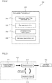
- Fig. 3 is a flowchart illustrating the outline of simulation processing by the material shape simulation apparatus 100.
- the orientation vector field generation unit 210 is caused to determine a fiber direction vector for a tetrahedron element, which is each mesh of the model shape, and creates an initial orientation vector (step S11) as illustrated in this drawing.
- the parameterization unit 220 searches for a map f from the model shape to the material shape (step S12). When this happens, the map f may be searched for by performing parameterization such as the Taylor expansion.
- the orientation vector updating unit 230 is caused to update the material shape obtained by the parameterization to a model space by using specified conditions (step S13). Step S12 and step S13 are repeated.
- the nonlinear optimization unit 240 is caused to perform optimization to minimize energy of fiber-bundle-direction strain and volumetric strain (step S20).
- the processing is terminated as a result of repeating the parameterization processing and the orientation vector update processing. The processing of each processing block will be explained below in detail.
- Fig. 4 is a diagram schematically illustrating the relationship between coordinates on the model shape and the material shape by the simulation processing.
- a mesh vertex p i of the model space (x, y, z) is mapped to a vertex f(p i ) of the material space (X, Y, Z) by a mapping function f as illustrated in this drawing, an orientation vector is known as an ideal gradient vector of the mapping function f.
- the mapping function f is expressed as Formula (1)
- gradient vectors of the mapping function f are expressed as Formula (2).
- ⁇ Y ⁇ Y ⁇ x ⁇ Y ⁇ y ⁇ Y ⁇ z
- ⁇ Z ⁇ Z ⁇ x ⁇ Z ⁇ y ⁇ Z ⁇ z .
- the ideal gradient vector is evaluated by each repetitive processing and the obtained ideal gradient vectors are called "orientation vectors."
- Each set of the three orientation vectors is assigned to a tetrahedron and an orientation vector field is used as a guidance field during the parameterization processing.
- Formula (3) is expressed as Jacobian matrixes of the mapping functions f and f -1 .
- J f ⁇ X ⁇ x ⁇ X ⁇ y ⁇ X ⁇ z ⁇ Y ⁇ x ⁇ Y ⁇ y ⁇ Y ⁇ z ⁇ Z ⁇ x ⁇ Z ⁇ y ⁇ Z ⁇ z
- J f ⁇ 1 ⁇ x ⁇ X ⁇ x ⁇ Y ⁇ x ⁇ Z ⁇ y ⁇ X ⁇ ⁇ ⁇ ⁇ Y ⁇ y ⁇ Z ⁇ z ⁇ X ⁇ z ⁇ Y ⁇ z ⁇ Z .
- Fiber directions in a model space are set as F d x , F d y , F d y and these are explicitly expressed as Formula (6) below by applying the Jacobian matrix J f-1 to F x , F y , F y .
- F X d ⁇ x ⁇ X ⁇ y ⁇ X ⁇ z ⁇ X
- F Y d ⁇ x ⁇ Y ⁇ y ⁇ Y ⁇ z ⁇ Y
- F z d ⁇ x ⁇ Z ⁇ y ⁇ Z ⁇ z ⁇ Z .
- Formula (7) shows the relationship between the orientation vectors and the fiber directions in the model space.
- the set of these vectors can be deformed mutually by using Formula (7).
- the fiber direction vectors are assigned at a boundary of a curved surface of the model shape. These fiber direction vectors are defined by a tangent space of the curved surface and specified at a triangular surface area of a boundary surface.
- the fiber direction vectors are calculated with respect to each tetrahedron of the model shape and are deformed to the model shape orientation vector field by using Formula (7).
- a fiber direction field is calculated based on specific fiber directions by employing the following steps 1 and 2.
- step 1 it is necessary to perform global minimization of changes in the vectors of the adjacent triangles in order to obtain a smooth vector field; and this becomes a nonlinear problem. Under this circumstance, the nonlinear problem may be solved; however, this embodiment is designed to repeat local minimization by using an average value of angular differences of the vectors of the adjacent triangles.
- Fig. 5 illustrates how the fiber direction vectors propagate on the curved surface from an edge area where boundary conditions are set in step 1. Firstly, as illustrated in this drawing, the fiber direction vectors in a border area are set (step S31) and propagated (step S32), thereby generating the fiber direction vector field (step S33).
- the smooth vector field can be obtained by using an average polar coordinate value of the adjacent tetrahedrons in the same manner.
- the fiber direction vectors can be located in each mesh by the above-described method.
- Formula (7) is applied to the obtained fiber direction vectors, thereby deforming them to model shape orientation vectors.
- NPL 2 to NPL 5 methods for making a three-dimensional curved surface corresponds to a two-dimensional Euclidean space are described in NPL 2 to NPL 5.
- a method similar to NPL 6 and NPL 7 is employed to use a guidance vector field in which a 3-maniforld is made to correspond to a three-dimensional Euclidean space.
- a set of orientation vectors at an edge are defined by the following Formula (8) and coordinates (p i , p j ) of a mapped vertex are expressed by the following Formula (9).
- ( ⁇ X) Eij , ( ⁇ Y) Eij , ( ⁇ Z) Eij may be calculated by obtaining an average of the orientation vectors ( ⁇ X) Tk , ( ⁇ Y) Tk , ( ⁇ Z) Tk with respect to all tetrahedrons Tk.
- Each equation of this Formula (11) is minimized. When this happens, minimization of this formula is a linear problem and a conjugate gradient method may be applied. As a result, the gradient vectors for mapping from the model shape to the material shape can be found.
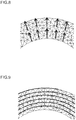
- Fig. 6 to Fig. 9 are diagrams illustrating examples of two-dimensional parameterization using the model shape orientation vector field.
- Fig. 6 and Fig. 8 represent distribution of the model shape orientation vector field; and
- Fig. 7 and Fig. 9 are diagram showing the results of parameterization corresponding to Fig. 6 and 8 , respectively, as indicated with isoplethic lines.
- Formula (10) is necessarily satisfied and the fiber direction vectors calculated from the gradient vectors of the mapping are different from desired results and deformation energy values become high.
- the processing of the orientation vector updating unit in the next section is to improve the orientation vector field on the basis of the results of this parameterization.
- the processing of the orientation vector updating unit 230 is to update the orientation vector field based on a gradient filed.
- Fig. 10 is a diagram for explaining the orientation vector update processing. Deformation of a hexahedron with their sides formed of the fiber directions is expressed as illustrated in this drawing and a continuum deformation amount is used to explain local deformation. Referring to Fig. 19 , inclination and expansion of the Z-yarn occur more easily than slippage movements of the X-yarn and the Y-yarn relative to each other at intersections between the X-yarn and the Y-yarn.
- the gradient vectors (VX)f, (VY)f, and (VZ)f obtained by the processing of the parameterization unit are used in order to obtain Formula (13) for updating the orientation vectors.
- directions of the gradient vectors (VX)f, (VY)f, and (VZ)f are adopted as directions of the orientation vectors VX, VY, and VZ and Formula (13) is used to determine the norm of the gradient vectors. Since the gradient of the mapping can be deformed in the fiber directions by using Formula (7), the norm of the vectors can be adjusted by using the fiber directions obtained by the parameterization so that the adjustment will be reflected in the actual deformation phenomenon of the fiber material.
- Fig. 11 to Fig. 14 are diagrams showing application results of the processing for repeating the parameterization processing and the orientation vector update processing in a case of two dimensions.
- Fig. 11 is the result of first repetitive processing
- Fig. 12 is the result of 7th repetitive processing
- Fig. 13 is the result of 20th repetitive processing
- Fig. 14 is the result of 87th repetitive processing.
- Solid lines represent coordinate lines mapped to the material space and correspond to the fiber directions in the model space.
- the X-yarn expands considerably and the shearing strain rarely occurs. Accordingly, the first repetition result as illustrated in Fig. 11 is different from the actual deformation phenomenon.
- the orientation of each yarn, particularly the Z-yarn, for the model shape and the material shape can be simulated accurately by assuming that the strain between the X-yarn and the Y-yarn does not occur and only the shearing strain between the X/Y-yarn and the Z-yarn occurs.
- the above-described repetition of the parameterization processing and the processing for updating the orientation vectors can indirectly minimize an energy function and roughly estimate the correspondence between the model shape and the material shape.
- the processing of this nonlinear optimization unit 240 can be used to accurately estimate the material shape and is the processing for directly minimizing a deformation energy function.
- the deformation energy function in consideration of a deformation mode of the three-dimensional woven fiber material can be expressed by the following Formula (14). [Math. 12] E ⁇ w X E X + w Y E Y + w Z E Z + w vol E vol .
- E X , E Y , and E Z are strain energy of X, Y, and Z, respectively and Evol is volume strain energy.
- Evol volume strain energy.
- w X , w Y , w Z , and w vol is a weighting parameter and can be determined based on experimental deformation results of the three-dimensional woven fiber material.
- This formula may be used to evaluate the deformation energy and be used as a condition to terminate the repetition of the parameterization processing and the orientation vector update processing. However, other termination conditions such as a specified number of times or any changes occurred in the results may be used and the deformation energy function may not be used. Since the strain energy of the model shape can be mitigated by executing the nonlinear optimization processing, the orientation of each yarn, particularly the Z-yarn, of the model shape can be simulated more accurately.
- p k and ⁇ k are a search direction and step size for the k-the repetition.
- a gradient direction of the deformation energy E can be used to determine the search direction P.
- NPL 8 can be used to find the step size ⁇ k .
- Fig. 15 and Fig. 16 are diagrams illustrating simulation results of deformation of the shape of a machine part by using the material shape simulation apparatus according to this embodiment.
- Fig. 15 shows a model shape
- Fig. 16 shows a material shape; and as illustrated in these drawings, it can be seen that the orientation of fibers designated in the model shape simulates that of the material shape in consideration of thickness.
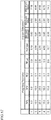
- Fig. 17 is a chart indicating angular errors of the Z-yarn between actual objects and the simulation results due to differences in the weighting parameters. According to this chart, the third example has the minimum error.
- the weighting parameter w Z should be defined as equal to or less than one hundredth (1/100) of the weighting parameter w X or w Y , or more preferably equal to or less than two one-hundredths (1/200) of the weighting parameter wx or w Y .
- the weighting parameter w vol should be equal to or less than one-fifth (1/5) of the weighting parameter wx or w Y , or more preferably equal to or less than one tenth (1/10) of the weighting parameter wx or w Y .
- the simulation can be performed more accurately also in a quantitative sense by determining the weighting parameters as described above.
- the material shape simulation apparatus 100 includes: the orientation vector field generation unit 210 that generates a model shape orientation vector field on three-dimensional meshes of a model shape of a three-dimensional woven fiber material which is obtained by stacking a plurality of sheets of two-dimensional woven fabric made of X-yarn extending in an X-direction and Y-yarn extending in a Y-direction and binding them with Z-yarn extending in a Z-direction; the parameterization unit 220 that searches for a gradient vector for calculating a material shape orientation vector field, which is an orientation vector field of a material shape before deformation of the model shape, from the model shape orientation vector field; and the orientation vector updating unit 230 that updates the model shape orientation vector field by applying a condition of preserving a volume between the model shape orientation vector field and the material shape orientation vector field and a condition that neither the X-yarn nor the Y-yarn expands or contracts. Therefore, the material shape simulation apparatus 100 can simulate the deformation
- the present disclosure can be applied to deformation of the three-dimensional woven fiber material.
Landscapes
- Engineering & Computer Science (AREA)
- Physics & Mathematics (AREA)
- Theoretical Computer Science (AREA)
- General Physics & Mathematics (AREA)
- Computer Hardware Design (AREA)
- Evolutionary Computation (AREA)
- Geometry (AREA)
- General Engineering & Computer Science (AREA)
- Manufacturing & Machinery (AREA)
- Textile Engineering (AREA)
- Human Computer Interaction (AREA)
- Automation & Control Theory (AREA)
- Woven Fabrics (AREA)
- Management, Administration, Business Operations System, And Electronic Commerce (AREA)
- Moulding By Coating Moulds (AREA)
- Nonwoven Fabrics (AREA)
Abstract
Description
- The present disclosure relates to a material shape simulation apparatus, a material shape simulation method, and a three-dimensional woven fiber component manufacturing method and is suited for use in, for example, a three-dimensional woven fiber material.
- In recent years, fiber-reinforced composite materials have come to be used in various fields. A fiber-reinforced composite material is a composite material manufactured by combining fibers with a support material; and since the fiber-reinforced composite materials have excellent material properties, that is, light weight and high strength as compared with single materials, the fiber-reinforced composite materials have been attracting attention as they can be used for components of, for example, aircrafts and vehicles. Examples of the fiber-reinforced composite materials include CMC (Ceramic Matrix Composites) and FRP (Fiber Reinforced Plastics) and different types of the fiber-reinforced composite materials are selected and used as appropriate depending on, for example, the environment to be used and the intended use.
- Such fiber-reinforced composite materials have particularly high strength with respect to force in fiber directions, so that component shapes or the like are often formed by bending the fiber-reinforced composite materials without performing processing such as cutting in order to make use of the above-described properties. Therefore, a material shape of a flat plate for forming an intended three-dimensionally designed shape by means of bending is simulated and predicted by numerical calculation.
-
PTL 1 discloses a method for simulating the surface effect of woven fabric after being woven by using a weave diagram of woven fabric.PTL 2 discloses a plain-woven film material analysis system in which a weave shape of warp yarn and weft yarn is expressed as a waviness coefficient and deformation of this woven fabric is expressed as a continuous function with respect to a space.PTL 3 discloses a design method including: a step of acquiring shape data representing an outer surface of a component; a step of determining, with respect to each point of a set of points on the outer surface, the distance between the point and a projection of the point onto a target surface; and a step of determining the structure of a three-dimensional woven preform according to the determined distance. -
- PTL 1: Japanese Patent Application Laid-Open (Kokai) Publication No.
2004-292976 - PTL 2: Japanese Patent Application Laid-Open (Kokai) Publication No.
2004-009543 - PTL 3: Japanese Patent Application Laid-Open (Kokai) Publication No.
2015-506007 -
- NPL 1: A. Hertzmann, D. Zorin, Illustrating smooth surfaces, in: Proceedings of the 27th annual conference on Computer graphics and interactive techniques, 2002.
- NPL 2: K. Hormann, G. Greiner, Mips: An efficient global parameterization method, in: P. P. L. Schumaker (Ed.), Composites Part A: Applied Science and Manufacturing: Saint-Malo 1999, Vanderbilt University Press, 2000.
- NPL 3: P. V. Sander, J. Snyder, S. J. Gortler, H. Hoppe, Texture mapping progressive meshes, in: Proceedings of ACM SIGGRAPH, ACM, 2001.
- NPL 4: M. Desbrun, M. Meyer, P. Alliez, Intrinsic parameterizations of surface meshes, in: Computer Graphics Forum, Vol. 21(3), 2002.
- NPL 5: B. Levy, S. Petitjean, N. Ray, J. Maillot, Least squares conformal maps for automatic texture atlas generation, in: ACM SIGGRAPH conference proceedings, 2002.
- NPL 6: M. Nieser, U. Reitebuch, K. Polthier, Cube cover - parameterization of 3d volumes, in: Computer Graphics Forum, Vol. 30, 2011.
- NPL 7: Y. Li, Y. Liu, W. Xu, W. Wang, B. Cuo, All-hex meshing using singularity-restricted field, in: ACM Transactions on Graphics - Proceddings of ACM SIGGRAPH Asia 2012, Vol. 31(6), 2012.
- NPL 8: J. Nocedal, S. J. Wright, Numerical Optimization, 2nd Edition, Springer Series in Operations Research, Springer Science+Business Media, LLC, 2006.
-
Fig. 18 a diagram illustrating an example of a fiber-reinforced composite material manufacturing process. Regarding the manufacturing process as illustrated in this drawing, a three-dimensional model shape and its fiber directions of, for example, a component are firstly determined (S61); and a material shape which is to be formed and bent into a model shape by means of, for example, simulation is calculated (S62). Next, the calculated material shape is applied to a fiber material (S63); and the fiber material is deformed by, for example, bending it and thereby formed into a product shape (S64). Lastly, the model shape and the product shape are compared and evaluated. The simulation as used in step S61 to calculate the material shape for forming the three-dimensional model shape is often designed to simulate each of two-dimensional woven fiber materials for a front surface and back surface of the model shape in two dimensions and predict a flat plate shape by making the simulated front and back surfaces correspond to each other. - However, the three-dimensional woven fiber material is formed by stacking up thin plates of plain-woven fibers made of
X-yarn 11 and Y-yarn 12 and binding the plurality of thin plates with Z-yarn 13 as illustrated inFig. 19 , so that the three-dimensional woven fiber material shows different fiber directions and has an anisotropic structural property.Fig. 20 is a diagram showing a CT (Computed Tomography) image of a cross section of the three-dimensional woven fiber material which is deformed. The fiber material of this image is deformed along an arc around acenter point 81. Sections indicated in white are sections where the X-yarn and the Y-yarn intersect with each other and it can be seen that those sections are moved towards the direction of the Z-yarn 13. If this material were isotropic, the Z-yarn 13 should have coincided withradial lines 82 extending from thecenter point 81. However, the Z-yarn 13 does not match deformation directions and is inclined. Accordingly, the X-yarn and the Y-yarn show different deformation properties from those of plain-woven fibers because of the Z-yarn. Therefore, it is difficult to accurately simulate the deformation of the three-dimensional woven fiber material by using the simulation of the two-dimensional woven fiber material. - The present disclosure was devised in consideration of the above-described circumstances and aims at providing an apparatus and method for more accurately simulating a material shape that simulates the deformation of the three-dimensional woven fiber material.
- In order to solve the above-described problem, a material shape simulation apparatus according to the present disclosure includes: an orientation vector field generation unit that generates a model shape orientation vector field on three-dimensional meshes of a model shape of a three-dimensional woven fiber material which is obtained by stacking a plurality of sheets of two-dimensional woven fabric made of X-yarn extending in an X-direction and Y-yarn extending in a Y-direction and binding them with Z-yarn extending in a Z-direction; a parameterization unit that searches for a gradient vector for calculating a material shape orientation vector field, which is an orientation vector field of a material shape before deformation of the model shape, from the model shape orientation vector field; and an orientation vector updating unit that updates the model shape orientation vector field by applying a condition of preserving a volume between the model shape orientation vector field and the material shape orientation vector field and a condition that neither the X-yarn nor the Y-yarn expands or contracts.
- Furthermore, a material shape simulation method according to the present disclosure includes: generating a model shape orientation vector field on three-dimensional meshes of a model shape of a three-dimensional woven fiber material which is obtained by stacking a plurality of sheets of two-dimensional woven fabric made of X-yarn extending in an X-direction and Y-yarn extending in a Y-direction and binding them with Z-yarn extending in a Z-direction; searching for a gradient vector for calculating a material shape orientation vector field, which is an orientation vector field of a material shape before deformation of the model shape, from the model shape orientation vector field; and updating the model shape orientation vector field by applying a condition of preserving a volume between the model shape orientation vector field and the material shape orientation vector field and a condition that neither the X-yarn nor the Y-yarn expands or contracts.
- Furthermore, a three-dimensional woven fiber component manufacturing method according to the present disclosure includes: calculating a material shape by the above-described material shape simulation method; creating a three-dimensional woven fiber material of the calculated material shape; and forming a three-dimensional woven fiber component by deforming the three-dimensional woven fiber material.
- According to the present disclosure, the deformation of the three-dimensional woven fiber material can be simulated more accurately.
-
-
Fig. 1 is a diagram illustrating a hardware configuration of a material shape simulation apparatus according to an embodiment of the present disclosure; -
Fig. 2 is a block diagram illustrating a functional configuration of a computation processing unit for the material shape simulation apparatus; -
Fig. 3 is a flowchart illustrating the outline of simulation processing by the material shape simulation apparatus; -
Fig. 4 is a diagram schematically illustrating the relationship between coordinates on a model shape and a material shape by the simulation processing; -
Fig. 5 is a diagram illustrating how fiber direction vectors propagate on a curved surface from an edge area where boundary conditions are set; -
Fig. 6 is a diagram illustrating an example of distribution of an orientation vector field; -
Fig. 7 is a diagram illustrating an example of parameterization in the distribution inFig. 6 ; -
Fig. 8 is a diagram illustrating an example of distribution of an orientation vector field; -
Fig. 9 is a diagram illustrating an example of parameterization in the distribution inFig. 8 ; -
Fig. 10 is a diagram for explaining orientation vector update processing; -
Fig. 11 is a diagram illustrating the result of first repetitive processing of parameterization processing and orientation vector update processing in a case of two dimensions; -
Fig. 12 is a diagram illustrating the result of 7th repetitive processing of the parameterization processing and the orientation vector update processing in the case of the two dimensions; -
Fig. 13 is a diagram illustrating the result of 20th repetitive processing of the parameterization processing and the orientation vector update processing in the case of the two dimensions; -
Fig. 14 is a diagram illustrating the result of 87th repetitive processing of the parameterization processing and the orientation vector update processing in the case of the two dimensions; -
Fig. 15 is a diagram illustrating the result of simulating a model shape regarding an example of a machine part; -
Fig. 16 is a diagram illustrating the result of simulating a material shape regarding the example of the machine part inFig. 15 ; -
Fig. 17 is a table indicating error differences caused by differences in weighting parameters for a deformation energy function; -
Fig. 18 is a diagram illustrating an example of a fiber-reinforced composite material manufacturing process; -
Fig. 19 is a diagram schematically illustrating a woven structure of a three-dimensional woven fiber material; and -
Fig. 20 is a diagram illustrating an example of a cross section of the three-dimensional woven fiber material which is deformed. - An embodiment of the present disclosure will be explained below in detail with reference to the drawings. In the following explanation, the same reference numeral is assigned to similar elements and any duplicate explanation is omitted.
-
Fig. 1 is a diagram illustrating a hardware configuration of a materialshape simulation apparatus 100 according to this embodiment. The materialshape simulation apparatus 100 may be configured of a CPU (Central Processing Unit) 201, avolatile storage unit 202 such as a RAM (Random Access Memory), anonvolatile storage unit 203 such as a hard disk and a flash memory, aninput device 500 such as a keyboard and a mouse, and adisplay device 400 including, for example, a liquid display screen as illustrated in this drawing. Under this circumstance, theCPU 201, thevolatile storage unit 202, and thenonvolatile storage unit 203 constitute acomputation processing unit 200 that is operated by software. Incidentally, the materialshape simulation apparatus 100 may be configured of a computer system to which a computer apparatus of the hardware configuration as illustrated inFig. 1 is connected via a network. -
Fig. 2 is a block diagram illustrating a functional configuration of thecomputation processing unit 200 for the materialshape simulation apparatus 100. Thecomputation processing unit 200 for the materialshape simulation apparatus 100 as illustrated in this drawing includes: an orientation vectorfield generation unit 210 that generates a model shape orientation vector field on three-dimensional meshes of a model shape of a three-dimensional woven fiber material which is obtained by stacking a plurality of sheets of two-dimensional woven fabric made of X-yarn extending in an X-direction and Y-yarn extending in a Y-direction and binding them with Z-yarn extending in a Z-direction; aparameterization unit 220 that searches for a gradient vector for calculating a material shape orientation vector field, which is an orientation vector field of a material shape before deformation of the model shape, from the model shape orientation vector field; an orientationvector updating unit 230 that updates the model shape orientation vector field by applying a condition of preserving a volume between the model shape orientation vector field and the material shape orientation vector field and a condition that neither the X-yarn nor the Y-yarn expands or contracts; and anonlinear optimization unit 240 that further updates the model shape orientation vector field by minimizing strain energy of the model shape. Under this circumstance, thenonlinear optimization unit 240 is included in this embodiment; however, a configuration which does not include thenonlinear optimization unit 240 may also be employed. -
Fig. 3 is a flowchart illustrating the outline of simulation processing by the materialshape simulation apparatus 100. Firstly, the orientation vectorfield generation unit 210 is caused to determine a fiber direction vector for a tetrahedron element, which is each mesh of the model shape, and creates an initial orientation vector (step S11) as illustrated in this drawing. Next, theparameterization unit 220 searches for a map f from the model shape to the material shape (step S12). When this happens, the map f may be searched for by performing parameterization such as the Taylor expansion. Subsequently, the orientationvector updating unit 230 is caused to update the material shape obtained by the parameterization to a model space by using specified conditions (step S13). Step S12 and step S13 are repeated. Lastly, thenonlinear optimization unit 240 is caused to perform optimization to minimize energy of fiber-bundle-direction strain and volumetric strain (step S20). When thenonlinear optimization unit 240 is not included, the processing is terminated as a result of repeating the parameterization processing and the orientation vector update processing. The processing of each processing block will be explained below in detail. -
Fig. 4 is a diagram schematically illustrating the relationship between coordinates on the model shape and the material shape by the simulation processing. When a mesh vertex pi of the model space (x, y, z) is mapped to a vertex f(pi) of the material space (X, Y, Z) by a mapping function f as illustrated in this drawing, an orientation vector is known as an ideal gradient vector of the mapping function f. When the mapping function f is expressed as Formula (1), gradient vectors of the mapping function f are expressed as Formula (2).
[Math. 1]

- The ideal gradient vector is evaluated by each repetitive processing and the obtained ideal gradient vectors are called "orientation vectors." Each set of the three orientation vectors is assigned to a tetrahedron and an orientation vector field is used as a guidance field during the parameterization processing.
- These orientation vectors are directly related to fiber directions through explicit deformation rules. In order to show this, Formula (3) is expressed as Jacobian matrixes of the mapping functions f and f-1.
[Math. 2]
- These Jacobian matrixes have the following obvious relationship as indicated as Formula (4) below.
[Math. 3]
- Since the three-dimensional woven fiber material is formed with fiber threads that intersect with each other at right angles, X-yarn, Y-yarn, and Z-yarn of a material space are oriented in parallel with basic directions of an XYZ space. Furthermore, in consideration of the fact that the fiber threads in the material space neither expand nor contract, the X-yarn, Y-yarn, and Z-yarn in this space are expressed, respectively, as Formula (5) below.
[Math. 4]
- Fiber directions in a model space are set as Fd x, Fd y, Fd y and these are explicitly expressed as Formula (6) below by applying the Jacobian matrix Jf-1 to Fx, Fy, Fy.
[Math. 5]
- The following Formula (7) is derived by assigning Formulas (2) and (6) to Formula (3).
[Math. 6]
- Formula (7) shows the relationship between the orientation vectors and the fiber directions in the model space. The set of these vectors can be deformed mutually by using Formula (7).
- Processing by the orientation vector
field generation unit 210 for forming a model shape orientation vector field in each mesh will be explained. The fiber direction vectors are assigned at a boundary of a curved surface of the model shape. These fiber direction vectors are defined by a tangent space of the curved surface and specified at a triangular surface area of a boundary surface. In order to generate an initial orientation vector field, the fiber direction vectors are calculated with respect to each tetrahedron of the model shape and are deformed to the model shape orientation vector field by using Formula (7). A fiber direction field is calculated based on specific fiber directions by employing the followingsteps - Step 1: the fiber direction vectors of the curved surface at the boundary of the model shape are propagated.
- Step 2: the fiber direction vectors are propagated towards inside the model shape. Incidentally, methods other than those described above may be used to propagate the fiber direction vectors. the vectors are propagated by repeatedly calculating their average across adjacent triangles or tetrahedrons. Under this circumstance, Hertzmann's method of
NPL 1 may be used. - In
step 1, it is necessary to perform global minimization of changes in the vectors of the adjacent triangles in order to obtain a smooth vector field; and this becomes a nonlinear problem. Under this circumstance, the nonlinear problem may be solved; however, this embodiment is designed to repeat local minimization by using an average value of angular differences of the vectors of the adjacent triangles.Fig. 5 illustrates how the fiber direction vectors propagate on the curved surface from an edge area where boundary conditions are set instep 1. Firstly, as illustrated in this drawing, the fiber direction vectors in a border area are set (step S31) and propagated (step S32), thereby generating the fiber direction vector field (step S33). Instep 2, the smooth vector field can be obtained by using an average polar coordinate value of the adjacent tetrahedrons in the same manner. The fiber direction vectors can be located in each mesh by the above-described method. Formula (7) is applied to the obtained fiber direction vectors, thereby deforming them to model shape orientation vectors. - Regarding the parameterization, methods for making a three-dimensional curved surface corresponds to a two-dimensional Euclidean space are described in
NPL 2 toNPL 5. In this embodiment, a method similar to NPL 6 and NPL 7 is employed to use a guidance vector field in which a 3-maniforld is made to correspond to a three-dimensional Euclidean space. - A set of orientation vectors at an edge are defined by the following Formula (8) and coordinates (pi, pj) of a mapped vertex are expressed by the following Formula (9).
[Math. 7]

- Mapping conditions are expressed by the following Formula (10).
[Math. 8]
- When Formula (10) is satisfied, the gradient vectors coincide with specific orientation vectors. Under this circumstance, the following Formula (11) which is a minimization function is created to sum up square errors of Formula (10) with respect to all edges.
[Math. 9]
- (∇X)Eij, (∇Y)Eij, (∇Z)Eij may be calculated by obtaining an average of the orientation vectors (∇X)Tk, (∇Y)Tk, (∇Z)Tk with respect to all tetrahedrons Tk. Each equation of this Formula (11) is minimized. When this happens, minimization of this formula is a linear problem and a conjugate gradient method may be applied. As a result, the gradient vectors for mapping from the model shape to the material shape can be found.
-
Fig. 6 to Fig. 9 are diagrams illustrating examples of two-dimensional parameterization using the model shape orientation vector field.Fig. 6 andFig. 8 represent distribution of the model shape orientation vector field; andFig. 7 andFig. 9 are diagram showing the results of parameterization corresponding toFig. 6 and8 , respectively, as indicated with isoplethic lines. Regarding these results, Formula (10) is necessarily satisfied and the fiber direction vectors calculated from the gradient vectors of the mapping are different from desired results and deformation energy values become high. The processing of the orientation vector updating unit in the next section is to improve the orientation vector field on the basis of the results of this parameterization. - The processing of the orientation
vector updating unit 230 is to update the orientation vector field based on a gradient filed.Fig. 10 is a diagram for explaining the orientation vector update processing. Deformation of a hexahedron with their sides formed of the fiber directions is expressed as illustrated in this drawing and a continuum deformation amount is used to explain local deformation. Referring toFig. 19 , inclination and expansion of the Z-yarn occur more easily than slippage movements of the X-yarn and the Y-yarn relative to each other at intersections between the X-yarn and the Y-yarn. Specifically speaking, shearing strain between the X/Y-yarn and the Z-yarn and strain of the Z-yarn occur more easily than strain between the X-yarn and the Y-yarn. Therefore, it can be assumed that the strain between the X-yarn and the Y-yarn does not occur and only the shearing strain between the X/Y-yarn and the Z-yarn occurs. Since a norm of the XY fiber direction deformation of the model space is close to a norm of the XY fiber direction deformation of the material space and the expansion/contraction of the Z-yarn can be considered to be caused as a result of forced volume changes, consideration should be paid to preserve the volume. Therefore, the following Formula (12) is applied.
[Math. 10]
- Under this circumstance, when Formulas (5) and (7) are applied to Formula (12), conditions of the following Formula (13) can be obtained.
[Math. 11]
- The gradient vectors (VX)f, (VY)f, and (VZ)f obtained by the processing of the parameterization unit are used in order to obtain Formula (13) for updating the orientation vectors. Particularly, directions of the gradient vectors (VX)f, (VY)f, and (VZ)f are adopted as directions of the orientation vectors VX, VY, and VZ and Formula (13) is used to determine the norm of the gradient vectors. Since the gradient of the mapping can be deformed in the fiber directions by using Formula (7), the norm of the vectors can be adjusted by using the fiber directions obtained by the parameterization so that the adjustment will be reflected in the actual deformation phenomenon of the fiber material. In this embodiment, the above-mentioned Formula (12) or (13) is applied; however, without limitation to these formulas, it is possible to apply a formula meaning the assumption that the strain between the X-yarn and the Y-yarn does not occur and only the shearing strain between the X/Y-yarn and the Z-yarn occurs.
-
Fig. 11 to Fig. 14 are diagrams showing application results of the processing for repeating the parameterization processing and the orientation vector update processing in a case of two dimensions.Fig. 11 is the result of first repetitive processing;Fig. 12 is the result of 7th repetitive processing;Fig. 13 is the result of 20th repetitive processing; andFig. 14 is the result of 87th repetitive processing. Solid lines represent coordinate lines mapped to the material space and correspond to the fiber directions in the model space. Regarding the result of the first repetitive processing illustrated inFig. 11 , the X-yarn expands considerably and the shearing strain rarely occurs. Accordingly, the first repetition result as illustrated inFig. 11 is different from the actual deformation phenomenon. As the repetitive processing proceeds, the extraction of the X-yarn decreases and the shearing strain between the X-yarn and the Y-yarn increases as illustrated in the repetition results ofFig. 12 to Fig. 14 . Therefore, the orientation of each yarn, particularly the Z-yarn, for the model shape and the material shape can be simulated accurately by assuming that the strain between the X-yarn and the Y-yarn does not occur and only the shearing strain between the X/Y-yarn and the Z-yarn occurs. - The above-described repetition of the parameterization processing and the processing for updating the orientation vectors can indirectly minimize an energy function and roughly estimate the correspondence between the model shape and the material shape. The processing of this
nonlinear optimization unit 240 can be used to accurately estimate the material shape and is the processing for directly minimizing a deformation energy function. The deformation energy function in consideration of a deformation mode of the three-dimensional woven fiber material can be expressed by the following Formula (14).
[Math. 12]
- Regarding this formula, EX, EY, and EZ are strain energy of X, Y, and Z, respectively and Evol is volume strain energy. Under this circumstance, a continuum can be assumed for calculation of each energy and the Young's modulus can be used for the calculation. Each of wX, wY, wZ, and wvol is a weighting parameter and can be determined based on experimental deformation results of the three-dimensional woven fiber material. This formula may be used to evaluate the deformation energy and be used as a condition to terminate the repetition of the parameterization processing and the orientation vector update processing. However, other termination conditions such as a specified number of times or any changes occurred in the results may be used and the deformation energy function may not be used. Since the strain energy of the model shape can be mitigated by executing the nonlinear optimization processing, the orientation of each yarn, particularly the Z-yarn, of the model shape can be simulated more accurately.
- In order to minimize this nonlinear function, it is possible to use, for example, a linear search method according to Formula (15) below which expresses k-th repetition in a case where an initial solution is xo.
[Math. 13]
- Regarding the above formula, pk and αk are a search direction and step size for the k-the repetition. Under this circumstance, a gradient direction of the deformation energy E can be used to determine the search direction P. Furthermore, NPL 8 can be used to find the step size αk.
-
Fig. 15 andFig. 16 are diagrams illustrating simulation results of deformation of the shape of a machine part by using the material shape simulation apparatus according to this embodiment.Fig. 15 shows a model shape andFig. 16 shows a material shape; and as illustrated in these drawings, it can be seen that the orientation of fibers designated in the model shape simulates that of the material shape in consideration of thickness.Fig. 17 is a chart indicating angular errors of the Z-yarn between actual objects and the simulation results due to differences in the weighting parameters. According to this chart, the third example has the minimum error. It is preferable as indicated in this chart that the weighting parameter wZ should be defined as equal to or less than one hundredth (1/100) of the weighting parameter wX or wY, or more preferably equal to or less than two one-hundredths (1/200) of the weighting parameter wx or wY. Furthermore, it is preferable that the weighting parameter wvol should be equal to or less than one-fifth (1/5) of the weighting parameter wx or wY, or more preferably equal to or less than one tenth (1/10) of the weighting parameter wx or wY. The simulation can be performed more accurately also in a quantitative sense by determining the weighting parameters as described above. - The material
shape simulation apparatus 100 according to this embodiment includes: the orientation vectorfield generation unit 210 that generates a model shape orientation vector field on three-dimensional meshes of a model shape of a three-dimensional woven fiber material which is obtained by stacking a plurality of sheets of two-dimensional woven fabric made of X-yarn extending in an X-direction and Y-yarn extending in a Y-direction and binding them with Z-yarn extending in a Z-direction; theparameterization unit 220 that searches for a gradient vector for calculating a material shape orientation vector field, which is an orientation vector field of a material shape before deformation of the model shape, from the model shape orientation vector field; and the orientationvector updating unit 230 that updates the model shape orientation vector field by applying a condition of preserving a volume between the model shape orientation vector field and the material shape orientation vector field and a condition that neither the X-yarn nor the Y-yarn expands or contracts. Therefore, the materialshape simulation apparatus 100 can simulate the deformation of the three-dimensional woven fiber material more accurately and calculate the material shape. - The present disclosure can be applied to deformation of the three-dimensional woven fiber material.
-
- 100
- material shape simulation apparatus
- 200
- computation processing unit
- 202
- volatile storage unit
- 203
- nonvolatile storage unit
- 210
- orientation vector field generation unit
- 220
- parameterization unit
- 230
- orientation vector updating unit
- 240
- nonlinear optimization unit
- 400
- display device
- 500
- input device
Claims (13)
- A material shape simulation apparatus comprising:an orientation vector field generation unit that generates a model shape orientation vector field on three-dimensional meshes of a model shape of a three-dimensional woven fiber material which is obtained by stacking a plurality of sheets of two-dimensional woven fabric made of X-yarn extending in an X-direction and Y-yarn extending in a Y-direction and binding them with Z-yarn extending in a Z-direction;a parameterization unit that searches for a gradient vector for calculating a material shape orientation vector field, which is an orientation vector field of a material shape before deformation of the model shape, from the model shape orientation vector field; andan orientation vector updating unit that updates the model shape orientation vector field by applying a condition of preserving a volume between the model shape orientation vector field and the material shape orientation vector field and a condition that neither the X-yarn nor the Y-yarn expands or contracts.
- The material shape simulation apparatus according to claim 1,
wherein the parameterization unit searches for the gradient vector by defining the gradient vector according to Formula (1) below with respect to a model space (x, y, z) and a material space (X, Y, Z)
[Math. 1]
[Math. 2]
- The material shape simulation apparatus according to claim 2,
wherein when the fiber directions of the material space are defined as Fx=(1, 0, 0), FY=(0, 1, 0), and Fz=(0, 0, 1), the orientation vector updating unit updates the model shape orientation vector field by applying Formula (3) below.
[Math. 3]
- The material shape simulation apparatus according to any one of claims 1 to 3,
wherein the orientation vector field generation unit sets a fiber direction vector at a boundary of the model shape, propagates the fiber direction vector to a curved surface of the model shape on the basis of on the fiber direction vector at the boundary, and propagates the fiber direction vector towards inside of the model shape on the basis of the fiber direction vector of the curved surface. - The material shape simulation apparatus according to any one of claims 1 to 4,
wherein when the gradient vector for an orientation vector Eij=(pi, pj) at an edge of the three-dimensional meshes is defined as ((X)Eij, (Y)Eij, (Z)Eij), the parameterization unit searches for the gradient vector so that values of right and left sides of Formula (4) below become as close to each other as possible.
[Math. 4]
- The material shape simulation apparatus according to claim 5,
wherein the gradient vector is searched for by minimizing each value calculated according to Formula (5) below.
[Math. 5]
- The material shape simulation apparatus according to any one of claims 1 to 6, further comprising a nonlinear optimization unit that further updates the model shape orientation vector field by minimizing strain energy of the model shape.
- The material shape simulation apparatus according to claim 7,
wherein when EX, EY, and EZ are strain energy of X, Y, and Z, respectively, Evol is volume strain energy, and wX, wY, and wZ are weighting values, the nonlinear optimization unit further updates the model shape orientation vector field by minimizing a value of Formula (6) below.
[Math. 6]
- The material shape simulation apparatus according to claim 8,
wherein a weighting parameter wZ is equal to or less than one hundredth (1/100) of a weighting parameter wX or wY. - The material shape simulation apparatus according to claim 8 or 9,
wherein a weighting parameter wvol is equal to or less than one-fifth (1/5) of the weighting parameter wX or wY. - The material shape simulation apparatus according to any one of claims 1 to 10, wherein each of the three-dimensional meshes is a tetrahedron.
- A material shape simulation method comprising:generating a model shape orientation vector field on three-dimensional meshes of a model shape of a three-dimensional woven fiber material which is obtained by stacking a plurality of sheets of two-dimensional woven fabric made of X-yarn extending in an X-direction and Y-yarn extending in a Y-direction and binding them with Z-yarn extending in a Z-direction;searching for a gradient vector for calculating a material shape orientation vector field, which is an orientation vector field of a material shape before deformation of the model shape, from the model shape orientation vector field; andupdating the model shape orientation vector field by applying a condition of preserving a volume between the model shape orientation vector field and the material shape orientation vector field and a condition that neither the X-yarn nor the Y-yarn expands or contracts.
- A three-dimensional woven fiber component manufacturing method comprising:calculating a material shape by the material shape simulation method stated in claim 12;creating a three-dimensional woven fiber material of the calculated material shape; andforming a three-dimensional woven fiber component by deforming the three-dimensional woven fiber material.
Applications Claiming Priority (2)
| Application Number | Priority Date | Filing Date | Title |
|---|---|---|---|
| JP2016037814A JP6680564B2 (en) | 2016-02-29 | 2016-02-29 | Material shape simulation device, material shape simulation method, and three-dimensional woven fiber component manufacturing method |
| PCT/JP2017/004287 WO2017150087A1 (en) | 2016-02-29 | 2017-02-06 | Material shape simulation device, material shape simulation method, and three-dimensional woven fiber article manufacturing method |
Publications (2)
| Publication Number | Publication Date |
|---|---|
| EP3425539A1 true EP3425539A1 (en) | 2019-01-09 |
| EP3425539A4 EP3425539A4 (en) | 2019-11-20 |
Family
ID=59743820
Family Applications (1)
| Application Number | Title | Priority Date | Filing Date |
|---|---|---|---|
| EP17759558.4A Pending EP3425539A4 (en) | 2016-02-29 | 2017-02-06 | MATERIAL SHAPE SIMULATION DEVICE, MATERIAL SHAPE SIMULATION METHOD, AND THREE DIMENSION WOVEN FIBER ARTICLE MANUFACTURING METHOD |
Country Status (7)
| Country | Link |
|---|---|
| US (1) | US10745832B2 (en) |
| EP (1) | EP3425539A4 (en) |
| JP (1) | JP6680564B2 (en) |
| CN (1) | CN108701166A (en) |
| CA (1) | CA3015878C (en) |
| RU (1) | RU2713855C1 (en) |
| WO (1) | WO2017150087A1 (en) |
Cited By (2)
| Publication number | Priority date | Publication date | Assignee | Title |
|---|---|---|---|---|
| WO2020244593A1 (en) * | 2019-06-05 | 2020-12-10 | 上海大学绍兴研究院 | Method for rapid reconstruction of woven composite material microstructure based on topological features |
| EP4206663A4 (en) * | 2020-12-28 | 2024-09-18 | IHI Corporation | Identification device, identification method, and identification program for identifying fiber layer in fiber-reinforced material |
Families Citing this family (5)
| Publication number | Priority date | Publication date | Assignee | Title |
|---|---|---|---|---|
| US10929971B2 (en) * | 2017-12-21 | 2021-02-23 | Rolls-Royce Corporation | Representation-based hybrid model |
| CN108804852A (en) * | 2018-06-28 | 2018-11-13 | 东汉新能源汽车技术有限公司 | The prediction technique and device of fiber alignment |
| CN109358568B (en) | 2018-12-17 | 2020-04-07 | 大连理工大学 | Vector field-based method for designing topological shape of machining track of curved surface partition |
| CN114547944B (en) * | 2022-03-02 | 2024-08-09 | 南京航空航天大学 | 2.5-Dimensional weaving composite material weft yarn fluctuation modeling method |
| CN115171819B (en) * | 2022-06-27 | 2025-05-23 | 西北工业大学 | Modeling method of unidirectional fiber periodic reinforced composite material containing fiber waviness |
Family Cites Families (13)
| Publication number | Priority date | Publication date | Assignee | Title |
|---|---|---|---|---|
| US5479593A (en) * | 1993-06-21 | 1995-12-26 | Electronic Data Systems Corporation | System and method for improved solving of equations employed during parametric geometric modeling |
| JPH08338795A (en) * | 1995-06-12 | 1996-12-24 | Ishikawajima Harima Heavy Ind Co Ltd | Three-dimensional composite material characteristic analysis method and analysis apparatus |
| JP2004009543A (en) * | 2002-06-06 | 2004-01-15 | Fuji Photo Film Co Ltd | Tentering device |
| JP3601718B2 (en) * | 2003-03-26 | 2004-12-15 | 株式会社トヨシマビジネスシステム | System for estimating fabric surface effect based on fabric structure, prediction method, and image processing system representing fabric surface effect |
| JP4232566B2 (en) * | 2003-07-15 | 2009-03-04 | トヨタ自動車株式会社 | Shape grasp method in numerical analysis by finite element |
| EP1526468B1 (en) * | 2003-10-17 | 2009-09-30 | Sumitomo Rubber Industries Limited | Method of simulating viscoelastic material |
| ES2424153T3 (en) * | 2004-07-02 | 2013-09-27 | Engenuity Limited | Crush modeling |
| JP4592471B2 (en) * | 2005-03-30 | 2010-12-01 | 富士通株式会社 | Shape prediction method, shape prediction apparatus, shape prediction program, and storage medium for injection molded product |
| RU2308763C2 (en) * | 2005-09-26 | 2007-10-20 | Государственное унитарное предприятие "Конструкторское бюро приборостроения" | Method for automatic construction of three-dimensional geometric model of product in geometric modeling system |
| TWI438041B (en) * | 2008-09-30 | 2014-05-21 | Nippon Steel & Sumitomo Metal Corp | Forming simulation method, forming simulation apparatus, forming simuration program and media for storing the program, and forming method using the simulation result |
| JP2013011504A (en) * | 2011-06-29 | 2013-01-17 | Ihi Corp | Method for evaluating delamination strength of composite material |
| FR2982518B1 (en) | 2011-11-15 | 2013-12-20 | Snecma | DESIGN OF A PIECE OF 3D COMPOSITE MATERIAL |
| RU2622211C2 (en) * | 2014-06-25 | 2017-06-13 | Акционерное общество "Всероссийский научно-исследовательский институт "Сигнал" (АО "ВНИИ "Сигнал") | Method of multicomponent products simulation in computer systems of two- and three-dimensional design |
-
2016
- 2016-02-29 JP JP2016037814A patent/JP6680564B2/en active Active
-
2017
- 2017-02-06 CA CA3015878A patent/CA3015878C/en active Active
- 2017-02-06 WO PCT/JP2017/004287 patent/WO2017150087A1/en not_active Ceased
- 2017-02-06 EP EP17759558.4A patent/EP3425539A4/en active Pending
- 2017-02-06 RU RU2018134188A patent/RU2713855C1/en active
- 2017-02-06 CN CN201780013759.5A patent/CN108701166A/en active Pending
-
2018
- 2018-08-29 US US16/116,086 patent/US10745832B2/en active Active
Cited By (4)
| Publication number | Priority date | Publication date | Assignee | Title |
|---|---|---|---|---|
| WO2020244593A1 (en) * | 2019-06-05 | 2020-12-10 | 上海大学绍兴研究院 | Method for rapid reconstruction of woven composite material microstructure based on topological features |
| US11830112B2 (en) | 2019-06-05 | 2023-11-28 | Shaoxing Research Institute Of Shanghai University | Method for rapid reconstruction of woven composite material microstructure based on topological features |
| EP4206663A4 (en) * | 2020-12-28 | 2024-09-18 | IHI Corporation | Identification device, identification method, and identification program for identifying fiber layer in fiber-reinforced material |
| US12472706B2 (en) | 2020-12-28 | 2025-11-18 | Ihi Corporation | Identification device, identification method, and identification program for identifying fiber layer in fiber-reinforced material |
Also Published As
| Publication number | Publication date |
|---|---|
| CA3015878C (en) | 2020-09-08 |
| EP3425539A4 (en) | 2019-11-20 |
| RU2713855C1 (en) | 2020-02-07 |
| US20190040553A1 (en) | 2019-02-07 |
| CA3015878A1 (en) | 2017-09-08 |
| JP2017156867A (en) | 2017-09-07 |
| JP6680564B2 (en) | 2020-04-15 |
| WO2017150087A1 (en) | 2017-09-08 |
| US10745832B2 (en) | 2020-08-18 |
| CN108701166A (en) | 2018-10-23 |
Similar Documents
| Publication | Publication Date | Title |
|---|---|---|
| US10745832B2 (en) | Material shape simulation apparatus, material shape simulation method, and three-dimensional woven fiber component manufacturing method | |
| Liu et al. | A survey of modeling and optimization methods for multi-scale heterogeneous lattice structures | |
| Drach et al. | Processing of fiber architecture data for finite element modeling of 3D woven composites | |
| Dick et al. | A hexahedral multigrid approach for simulating cuts in deformable objects | |
| Paulino et al. | Bridging art and engineering using Escher-based virtual elements | |
| US11544423B2 (en) | Computer simulation of physical fluids on a mesh in an arbitrary coordinate system | |
| Park | Anisotropic output-based adaptation with tetrahedral cut cells for compressible flows | |
| Park et al. | Unstructured grid adaptation and solver technology for turbulent flows | |
| EP2390802A2 (en) | Fluid structure interaction simulation method and apparatus, and computer-readable storage medium | |
| Ha | Generalized isogeometric shape sensitivity analysis in curvilinear coordinate system and shape optimization of shell structures: YD Ha | |
| Navarro-Zafra et al. | Three-dimensional static and dynamic analysis of a composite cruciform structure subjected to biaxial loading: a discontinuum approach | |
| Balzani et al. | Construction of statistically similar representative volume elements | |
| CN107077517B (en) | Design support device, design support method, and program | |
| Remmers et al. | Isogeometric analysis for modelling of failure in advanced composite materials | |
| O’Hara et al. | Structural identification and simulation of a MAV forewing | |
| Umetani et al. | A responsive finite element method to aid interactive geometric modeling | |
| Valentini et al. | Interactive simulation of realistic flexible and tearable membrane using virtual reality and haptic force-feedback interface | |
| Köke et al. | A graph-based method for calculating draping strategies for the application of fiber-reinforced materials on arbitrary surfaces | |
| CN120317072B (en) | Method for quickly updating and outputting box section overall finite element model information | |
| Allmaras et al. | Output-based Mesh Adaptation Using Commercial Mesh Generation Software | |
| Kamal et al. | Finite Element Algorithm for Surface Flattening | |
| de Noronha | The numerical analysis of airplane windshields due to bird strike: a static study | |
| Freitag | S04: Structural mechanics | |
| Szałtys et al. | High-order 3D anisotropic hybrid mesh generation for high-reynolds number flows | |
| Martin et al. | Treatment of surface intersections for gradient-based aerodynamic shape optimization |
Legal Events
| Date | Code | Title | Description |
|---|---|---|---|
| STAA | Information on the status of an ep patent application or granted ep patent |
Free format text: STATUS: THE INTERNATIONAL PUBLICATION HAS BEEN MADE |
|
| PUAI | Public reference made under article 153(3) epc to a published international application that has entered the european phase |
Free format text: ORIGINAL CODE: 0009012 |
|
| STAA | Information on the status of an ep patent application or granted ep patent |
Free format text: STATUS: REQUEST FOR EXAMINATION WAS MADE |
|
| 17P | Request for examination filed |
Effective date: 20181001 |
|
| AK | Designated contracting states |
Kind code of ref document: A1 Designated state(s): AL AT BE BG CH CY CZ DE DK EE ES FI FR GB GR HR HU IE IS IT LI LT LU LV MC MK MT NL NO PL PT RO RS SE SI SK SM TR |
|
| AX | Request for extension of the european patent |
Extension state: BA ME |
|
| DAV | Request for validation of the european patent (deleted) | ||
| DAX | Request for extension of the european patent (deleted) | ||
| A4 | Supplementary search report drawn up and despatched |
Effective date: 20191017 |
|
| RIC1 | Information provided on ipc code assigned before grant |
Ipc: G06F 17/50 20060101AFI20191011BHEP |
|
| STAA | Information on the status of an ep patent application or granted ep patent |
Free format text: STATUS: EXAMINATION IS IN PROGRESS |
|
| 17Q | First examination report despatched |
Effective date: 20210707 |