US11830112B2 - Method for rapid reconstruction of woven composite material microstructure based on topological features - Google Patents
Method for rapid reconstruction of woven composite material microstructure based on topological features Download PDFInfo
- Publication number
- US11830112B2 US11830112B2 US17/291,730 US202017291730A US11830112B2 US 11830112 B2 US11830112 B2 US 11830112B2 US 202017291730 A US202017291730 A US 202017291730A US 11830112 B2 US11830112 B2 US 11830112B2
- Authority
- US
- United States
- Prior art keywords
- fiber bundles
- model
- μct
- microstructure
- woven
- Prior art date
- Legal status (The legal status is an assumption and is not a legal conclusion. Google has not performed a legal analysis and makes no representation as to the accuracy of the status listed.)
- Active, expires
Links
Images


Classifications
-
- G—PHYSICS
- G06—COMPUTING; CALCULATING OR COUNTING
- G06T—IMAGE DATA PROCESSING OR GENERATION, IN GENERAL
- G06T11/00—2D [Two Dimensional] image generation
- G06T11/003—Reconstruction from projections, e.g. tomography
-
- G—PHYSICS
- G06—COMPUTING; CALCULATING OR COUNTING
- G06T—IMAGE DATA PROCESSING OR GENERATION, IN GENERAL
- G06T11/00—2D [Two Dimensional] image generation
- G06T11/003—Reconstruction from projections, e.g. tomography
- G06T11/006—Inverse problem, transformation from projection-space into object-space, e.g. transform methods, back-projection, algebraic methods
-
- G—PHYSICS
- G06—COMPUTING; CALCULATING OR COUNTING
- G06T—IMAGE DATA PROCESSING OR GENERATION, IN GENERAL
- G06T17/00—Three dimensional [3D] modelling, e.g. data description of 3D objects
-
- G—PHYSICS
- G06—COMPUTING; CALCULATING OR COUNTING
- G06T—IMAGE DATA PROCESSING OR GENERATION, IN GENERAL
- G06T2207/00—Indexing scheme for image analysis or image enhancement
- G06T2207/10—Image acquisition modality
- G06T2207/10072—Tomographic images
- G06T2207/10081—Computed x-ray tomography [CT]
-
- G—PHYSICS
- G06—COMPUTING; CALCULATING OR COUNTING
- G06T—IMAGE DATA PROCESSING OR GENERATION, IN GENERAL
- G06T2211/00—Image generation
- G06T2211/40—Computed tomography
- G06T2211/416—Exact reconstruction
Definitions
- the present disclosure relates to the field of structural reconstruction, in particular to a method for rapid reconstruction of a woven composite material microstructure based on topological features.
- Three-dimensional woven composite material is a kind of composite material which weaves warp, weft and normal fiber bundles into a whole by using weaving technology and has the characteristics of material and structure integration. Because the damage caused by secondary processing is avoided, it not only has good physical and chemical characteristics such as high specific strength and specific stiffness of traditional composite materials, but also avoids the interlayer shear failure of traditional laminates of composite materials, which greatly improves the reliability of materials and reduces the cost. Therefore, three-dimensional woven composite materials have broad development prospects and are the mainstream materials for future aerospace development.
- a third method is to directly generate point cloud data based on tomographic images. According to the data reconstruction model, this modeling method is often cumbersome and easy to introduce errors.
- the present disclosure establishes a mesh model which forms a mapping relationship with the images, determines node and unit information by using the construction information of the mesh, and determines model material attributes by using image color information, thus reconstructing the finite element model.
- This method avoids the accumulation of errors in geometric reconstruction and mesh division, but it needs to deal with a large amount of data and has high calculation cost. This method is more suitable for dealing with multiphase randomly distributed materials.
- the present disclosure adopts X-ray computed tomography technology to obtain pictures of a 2.5-dimensional composite material microstructure.
- the matrix region is identified by threshold segmentation technology.
- Each matrix area is assumed to be a twisted quadrilateral structure, and four boundaries of each matrix area are identified and marked.
- the matrix area is used to identify the warp fiber bundles and weft fiber bundles of the preform.
- each identified picture is stacked to build a 2.5-dimensional microstructure three-dimensional model.
- the application scope of this method is relatively narrow, and it is not feasible for complex 3D orthogonal and 3D 4-directional weaving structures.
- the identified main body is the matrix without taking into account the weaving characteristics of the woven structure fiber bundles, and it is easy to cause model errors.
- the purpose of the present disclosure is to provide a method for rapid reconstruction of a woven composite material microstructure based on topological features, so as to improve the consistency between the model and the real structure.
- the present disclosure provides the following scheme.
- the present disclosure provides a method for rapid reconstruction of a woven composite material microstructure based on topological features, comprising the steps of:
- the ⁇ CT system is a CT system with other scanning accuracy.
- raw data scanned by the ⁇ CT system is processed by VGStudio or Avizo software to convert raw files into commonly used png graphics files.
- the microstructure model is a microscopic model or a topological model.
- the method has the following technical effects. 1)
- the model is highly consistent with the real structure; the present disclosure extracts the real characteristic parameters of the material by using CT tomography without damaging the material structure; and compared with the idealized model obtained by cutting the woven body to obtain material parameters or established by only using the weaving parameters, the reconstructed model of the present disclosure is more consistent with the real structure.
- FIG. 1 is a modeling flow chart of the present disclosure
- FIG. 2 - 1 is ⁇ CT scanning result and a reconstructed microscopic model of a 2D woven body according to an embodiment of the present disclosure
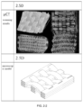
- FIG. 2 - 2 is ⁇ CT scanning result and a reconstructed microscopic model of a 2.5D woven body according to an embodiment of the present disclosure
- FIG. 2 - 3 is ⁇ CT scanning result and a reconstructed microscopic model of a 3D orthogonal woven body according to an embodiment of the present disclosure
- FIG. 2 - 4 is ⁇ CT scanning result and a reconstructed microscopic model of a 3D 4-directional woven body according to an embodiment of the present disclosure
- a method for rapid reconstruction of a woven composite material microstructure based on topological features takes the 2.5D woven structure shown in FIG. 2 - 2 as an example, comprising the following steps.
- the ⁇ CT system can use a CT system with other scanning accuracy.
- the raw data obtained by ⁇ CT scanning can be processed by VGStudio and Avizo software, which can obtain the same effect as ImageJ software.
- the microstructure model can be replaced by the concepts of a microscopic model and a topological model.
- FIGS. 2 - 1 , 2 - 3 and 2 - 4 they are ⁇ CT scanning results and reconstructed microscopic models of 2D, 3D orthogonal and 3D 4-directional woven bodies according to the present disclosure, respectively.
Landscapes
- Engineering & Computer Science (AREA)
- Physics & Mathematics (AREA)
- General Physics & Mathematics (AREA)
- Theoretical Computer Science (AREA)
- Mathematical Optimization (AREA)
- Algebra (AREA)
- Mathematical Analysis (AREA)
- Mathematical Physics (AREA)
- Pure & Applied Mathematics (AREA)
- Software Systems (AREA)
- Geometry (AREA)
- Computer Graphics (AREA)
- Analysing Materials By The Use Of Radiation (AREA)
- Woven Fabrics (AREA)
Abstract
Description
-
- 1) preparing a sample: preparing composite material samples with dimensions suitable for μCT test;
- 2) parametric modeling of the microstructure of a woven body: it is assumed that the weaving process is stable and the woven structure is uniform; the cross section of a fiber bundle is approximate to an ellipse, and spline curve is used as the axis of the fiber bundle to represent the trend of the fiber bundle, wherein parametric modeling is carried out for structures with different weaving methods to establish the topological model of a woven body;
- 3) scanning using a μCT system: scanning the composite material sample with a high-power microscopic μCT system to obtain the point cloud data of the composite material sample;
- 4) data processing: using ImageJ image processing software to process the raw data scanned by the μCT system, and converting the raw file into a common png graphic file; wherein the raw data is the point cloud data in step 3;
- 5) identification of phase components of the microstructure: different substances have different X-ray absorption coefficients, areas with composite materials and areas without composite materials show different gray scales in μCT scanning images, and various isotropic fiber bundles of the woven structure are identified according to the discontinuity of gray scales;
- 6) identification and extraction of the features of the fiber bundles of the microstructure: using the measuring tool in ImageJ software to obtain the characteristic parameters and structure parameters of the distance between bundles and the actual cross-section shape of fiber bundles at different spatial positions of the processed raw data, and then using the statistical average processing method to homogenize the change law of the measured parameters;
- 7) modification of a parametric model: according to the extracted characteristic parameters, modifying the spatial position of fiber bundles in the parametric microscopic model, and modifying the cross-sectional parameters of fiber bundles along the fiber bundle direction, so as to show the degree of deformation of fiber bundles under extrusion, in which at different positions, the fiber bundles have different degrees of deformation, thus obtaining a microscopic model with a high degree of consistency with the real structure.
-
- 2) The model reconstruction process is simple and fast, and the calculation cost is low: the present disclosure does not directly use the point cloud data of CT scanning sequence images to generate the model, but only extracts important woven body characteristic parameters, and the extraction method is simple and clear. Compared with directly generating the model by using the point cloud data, the present disclosure omits the complicated data processing process which is easy to introduce errors, and greatly reduces the calculation cost.
- 3) Wide application range: the present disclosure can be applied to the microscopic model reconstruction of composite materials with any known woven structure, and for composite materials with the same woven structure, only model parameters need to be changed according to characteristic parameters, and repeated modeling is not needed.
-
- Step 101: preparing a sample: 2.5D composite material samples with dimensions (length×height×width: 8750.76×4304.5×11670 μm) suitable for μCT test are prepared.
- Step 102: parametric modeling of the microstructure of a woven body: 2D structure is formed by warp fiber bundles and weft fiber bundles interwoven in the same plane, 2.5D structure is based on 2D, which interweaves weft fiber bundles with two layers of warp fiber bundles to form parallel multi-layer interweaving, taking ellipse as the fiber bundle cross section of 2.5D model, carrying out parametric modeling according to interweaving mode of warp fiber bundles and weft fiber bundles, and establishing topological model of a woven body.
- Step 103: scanning using a μCT system: the real 2.5D woven body with the same braiding parameters is scanned with a high-power microscopic μCT system to obtain the point cloud data of a woven body structure.
- Step 104: Data processing: ImageJ image processing software is used to process the raw data scanned by the μCT system, and the raw file is converted into a common png graphic file.
- Step 105: identification of phase components of the microstructure: different substances have different X-ray absorption coefficients, areas with materials and areas without materials show different gray scales in μCT scanning images, and warp fiber bundles and weft fiber bundles with 2.5D woven structure are identified according to the discontinuity of gray scales.
- Step 106: identification and extraction of the features of the fiber bundles of the microstructure: the measuring tool in ImageJ software is used to obtain the characteristic parameters and structure parameters of the distance between bundles and the actual cross-section shape of fiber bundles at different spatial positions, and then the statistical average processing method is used to homogenize the actually measured features and structure parameters. Under the influence of the weaving method, the weft fiber bundles are closely arranged, and the warp fiber bundles are squeezed by the weft fiber bundles everywhere. From the actually measured data of μCT scan images, it is known that the cross-sectional area of fiber bundles along the axial direction changes little and is ignorable. The cross-sectional area of warp fiber bundles is homogenized. The major axis of the elliptical cross-section is 1076 μm and the minor axis is 142.5 μm. The distance between warp fiber bundles is 2381 μm. The warp fiber bundles are loosely arranged and the distance between bundles is large, so that some weft fiber bundles are not in contact with the warp fiber bundles. From the actually measured data of μCT scanning images, it is known that the cross-sectional areas of the contacting part and the non-contacting part of the two fiber bundles change greatly and is non-ignorable. After homogenization, the maximum cross-sectional area at the center of the uncrossed part of two fiber bundles is 169,936 μm2, the major axis of the elliptical cross-section is 988 μm, the minor axis is 172 μm, the minimum cross-sectional area at the center of the crossed part of two fiber bundles is 157,573 μm2, the major axis of ellipse is 1105 μm, the minor axis is 142.6 μm, and the distance between weft fiber bundles is 1120 μm.
- Step 107: modification of a parametric model: according to the extracted characteristic parameters, the distance between bundles and the cross-sectional parameters of the warp fiber bundles and weft fiber bundles in the parametric microscopic model are modified to obtain a microscopic model with a high degree of consistency with the real structure.
Claims (4)
Applications Claiming Priority (3)
| Application Number | Priority Date | Filing Date | Title |
|---|---|---|---|
| CN201910487897.8 | 2019-06-05 | ||
| CN201910487897.8A CN110276814B (en) | 2019-06-05 | 2019-06-05 | A fast reconstruction method for the mesostructure of braided composites based on topological features |
| PCT/CN2020/094434 WO2020244593A1 (en) | 2019-06-05 | 2020-06-04 | Method for rapid reconstruction of woven composite material microstructure based on topological features |
Publications (2)
| Publication Number | Publication Date |
|---|---|
| US20220130082A1 US20220130082A1 (en) | 2022-04-28 |
| US11830112B2 true US11830112B2 (en) | 2023-11-28 |
Family
ID=67962027
Family Applications (1)
| Application Number | Title | Priority Date | Filing Date |
|---|---|---|---|
| US17/291,730 Active 2041-01-15 US11830112B2 (en) | 2019-06-05 | 2020-06-04 | Method for rapid reconstruction of woven composite material microstructure based on topological features |
Country Status (3)
| Country | Link |
|---|---|
| US (1) | US11830112B2 (en) |
| CN (1) | CN110276814B (en) |
| WO (1) | WO2020244593A1 (en) |
Families Citing this family (15)
| Publication number | Priority date | Publication date | Assignee | Title |
|---|---|---|---|---|
| CN110276814B (en) | 2019-06-05 | 2022-05-10 | 上海大学 | A fast reconstruction method for the mesostructure of braided composites based on topological features |
| CN111272870B (en) * | 2019-12-31 | 2023-03-14 | 中国航空制造技术研究院 | Method for determining weaving coefficient for ultrasonic detection of woven composite material |
| CN111882667B (en) * | 2020-07-27 | 2023-11-21 | 合肥工业大学 | Three-dimensional finite element modeling method of asphalt concrete based on mesostructure |
| EP3964824B1 (en) * | 2020-09-02 | 2024-02-14 | AT & S Austria Technologie & Systemtechnik Aktiengesellschaft | Expansion coefficient determination with deformation measurement and simulation |
| CN112164134B (en) * | 2020-09-28 | 2024-03-22 | 华南理工大学 | Random curve modeling method based on image processing |
| WO2022145091A1 (en) * | 2020-12-28 | 2022-07-07 | 株式会社Ihi | Identification device, identification method, and identification program for identifying fiber layer in fiber-reinforced material |
| CN113591556A (en) * | 2021-06-22 | 2021-11-02 | 长春理工大学 | Three-dimensional point cloud semantic analysis method based on neural network three-body model |
| CN114419284B (en) * | 2021-12-14 | 2025-06-17 | 南昌航空大学 | A three-dimensional reconstruction modeling method for fiber-reinforced composite materials based on CT slice images |
| CN114239276B (en) * | 2021-12-17 | 2024-07-23 | 南京航空航天大学 | Modeling method for 2.5-dimensional braided composite material microscopic structure fiber bundle |
| CN114719756B (en) * | 2022-03-17 | 2024-05-24 | 广州海关技术中心 | Method and system for measuring knitting density coefficient of knitted fabric |
| CN115017707B (en) * | 2022-06-08 | 2024-09-06 | 南京航空航天大学 | A 2.5-dimensional braided composite material modeling method based on pixel method |
| CN115082686B (en) * | 2022-08-22 | 2024-12-20 | 同济大学 | A toilet adhesive effect detection system using three-dimensional point cloud recognition method |
| CN115985421B (en) * | 2022-12-14 | 2025-05-13 | 重庆邮电大学 | A finite element modeling method for fabric composite materials based on micro-geometry model |
| CN118798005B (en) * | 2024-09-11 | 2025-01-07 | 湖南工程学院 | A global continuum modeling approach for realistic microstructures of composite materials |
| CN119227408B (en) * | 2024-10-14 | 2025-06-10 | 南京航空航天大学 | Mechanical property prediction method for woven composite material structure |
Citations (9)
| Publication number | Priority date | Publication date | Assignee | Title |
|---|---|---|---|---|
| CN102236737A (en) | 2011-07-14 | 2011-11-09 | 西安交通大学 | Method for reconstructing micro structure finite element of multiphase material based on sequence image |
| CN104268940A (en) | 2014-10-17 | 2015-01-07 | 中国石油大学(华东) | MEMS structure reconstruction and detection method based on CT scanned images |
| CN105803623A (en) | 2016-04-18 | 2016-07-27 | 南京航空航天大学 | Computer pattern recognition method for composite material microstructure |
| CN106202728A (en) | 2016-07-12 | 2016-12-07 | 哈尔滨工业大学 | Based on Micro CT D braided composites non-homogeneous Voxel grid discrete method |
| US9916651B2 (en) * | 2013-09-06 | 2018-03-13 | Safran | Method for characterizing a part made of a woven composite material |
| CN108932385A (en) | 2018-07-05 | 2018-12-04 | 北京航空航天大学 | A kind of modeling method of woven composite inside variable cross-section fibre bundle representativeness volume elements |
| EP3425539A1 (en) | 2016-02-29 | 2019-01-09 | IHI Corporation | Material shape simulation device, material shape simulation method, and three-dimensional woven fiber article manufacturing method |
| CN110276814A (en) | 2019-06-05 | 2019-09-24 | 上海大学 | A fast reconstruction method for the mesostructure of braided composites based on topological features |
| CN109241694B (en) | 2018-11-16 | 2021-04-13 | 南京航空航天大学 | Macro and micro integrated modeling method for woven ceramic matrix composite preform |
Family Cites Families (5)
| Publication number | Priority date | Publication date | Assignee | Title |
|---|---|---|---|---|
| CN102690124A (en) * | 2011-09-14 | 2012-09-26 | 中国人民解放军总后勤部军需装备研究所 | C/SiC ceramic matrix composite material and preparation method thereof |
| CN102867082B (en) * | 2012-08-29 | 2015-04-22 | 西北工业大学 | Laying spreading method for composite material |
| CN106093108B (en) * | 2016-05-19 | 2018-10-16 | 南京航空航天大学 | Unidirectional fibre toughening composition Equivalent Thermal Conductivities predictor method based on interstitial defect identification |
| CN107067472A (en) * | 2016-09-29 | 2017-08-18 | 北京理工大学 | A kind of geometric error characterizing method reconstructed based on nurbs surface |
| GB201806540D0 (en) * | 2018-03-06 | 2018-06-06 | Rolls Royce Plc | Surface or interface defect detection |
-
2019
- 2019-06-05 CN CN201910487897.8A patent/CN110276814B/en active Active
-
2020
- 2020-06-04 US US17/291,730 patent/US11830112B2/en active Active
- 2020-06-04 WO PCT/CN2020/094434 patent/WO2020244593A1/en active Application Filing
Patent Citations (9)
| Publication number | Priority date | Publication date | Assignee | Title |
|---|---|---|---|---|
| CN102236737A (en) | 2011-07-14 | 2011-11-09 | 西安交通大学 | Method for reconstructing micro structure finite element of multiphase material based on sequence image |
| US9916651B2 (en) * | 2013-09-06 | 2018-03-13 | Safran | Method for characterizing a part made of a woven composite material |
| CN104268940A (en) | 2014-10-17 | 2015-01-07 | 中国石油大学(华东) | MEMS structure reconstruction and detection method based on CT scanned images |
| EP3425539A1 (en) | 2016-02-29 | 2019-01-09 | IHI Corporation | Material shape simulation device, material shape simulation method, and three-dimensional woven fiber article manufacturing method |
| CN105803623A (en) | 2016-04-18 | 2016-07-27 | 南京航空航天大学 | Computer pattern recognition method for composite material microstructure |
| CN106202728A (en) | 2016-07-12 | 2016-12-07 | 哈尔滨工业大学 | Based on Micro CT D braided composites non-homogeneous Voxel grid discrete method |
| CN108932385A (en) | 2018-07-05 | 2018-12-04 | 北京航空航天大学 | A kind of modeling method of woven composite inside variable cross-section fibre bundle representativeness volume elements |
| CN109241694B (en) | 2018-11-16 | 2021-04-13 | 南京航空航天大学 | Macro and micro integrated modeling method for woven ceramic matrix composite preform |
| CN110276814A (en) | 2019-06-05 | 2019-09-24 | 上海大学 | A fast reconstruction method for the mesostructure of braided composites based on topological features |
Non-Patent Citations (2)
| Title |
|---|
| International Search Report of International Searching Authority for PCT/CN2020/094434, ISA/CN, Beijing, China, dated Aug. 17, 2020. |
| Written Opinion of International Searching Authority for PCT/CN2020/094434, ISA/CN, Beijing, China dated Aug. 17, 2020. |
Also Published As
| Publication number | Publication date |
|---|---|
| CN110276814A (en) | 2019-09-24 |
| CN110276814B (en) | 2022-05-10 |
| WO2020244593A1 (en) | 2020-12-10 |
| US20220130082A1 (en) | 2022-04-28 |
Similar Documents
| Publication | Publication Date | Title |
|---|---|---|
| US11830112B2 (en) | Method for rapid reconstruction of woven composite material microstructure based on topological features | |
| Naouar et al. | Meso-scale FE analyses of textile composite reinforcement deformation based on X-ray computed tomography | |
| Denos et al. | Fiber orientation measurement from mesoscale CT scans of prepreg platelet molded composites | |
| Ali et al. | Efficient processing of μCT images using deep learning tools for generating digital material twins of woven fabrics | |
| CN109242985B (en) | A method to determine key parameters of pore structure from 3D images | |
| Wernersson et al. | Characterisations of fibre networks in paper using micro computed tomography images | |
| CN106202728A (en) | Based on Micro CT D braided composites non-homogeneous Voxel grid discrete method | |
| Reh et al. | Porosity maps–interactive exploration and visual analysis of porosity in carbon fiber reinforced polymers | |
| Fang et al. | Micro-tomography based geometry modeling of three-dimensional braided composites | |
| Reh et al. | MObjects--A Novel Method for the Visualization and Interactive Exploration of Defects in Industrial XCT Data | |
| JP6681221B2 (en) | Structure analysis device, structure analysis method, and three-dimensional woven fiber material manufacturing method | |
| US7092484B1 (en) | Model-assisted reconstruction of volumetric data | |
| CN106233126B (en) | Methods for characterizing parts | |
| CN114419284A (en) | Fiber reinforced composite three-dimensional reconstruction modeling method based on CT slice image | |
| Varghese et al. | Unpaired image-to-image translation of structural damage | |
| Bai et al. | Digital core 3d reconstruction based on micro-ct images via a deep learning method | |
| Wang | Computing on rays: A parallel approach for surface mesh modeling from multi-material volumetric data | |
| JP2010091330A (en) | Method and system for analyzing orientation function | |
| Zheng et al. | Reverse reconstruction of geometry modeling and numerical verification of 2.5 D woven composites based on deep learning | |
| Peng et al. | Automatic 3D image based finite element modelling for metallic foams and accuracy verification of digital volume correlation | |
| Liu et al. | Integrating cross-sectional imaging based reverse engineering with rapid prototyping | |
| Srivastava et al. | Three-dimensional analysis of porosity in as-manufactured glass fiber/vinyl ester filament winded composites using X-ray micro-computed tomography | |
| Plank et al. | Evaluation and visualisation of shape factors in dependence of the void content within CFRP by means of X-ray computed tomography | |
| Lin et al. | Three-Dimensional-Slice-Super-Resolution-Net: A fast few shooting learning model for 3D super-resolution using slice-up and slice-reconstruction | |
| Liu et al. | Deep learning and integrated approach to reconstruct meshes from tomograms of 3D braided composites |
Legal Events
| Date | Code | Title | Description |
|---|---|---|---|
| AS | Assignment |
Owner name: SHANGHAI UNIVERSITY, CHINA Free format text: ASSIGNMENT OF ASSIGNORS INTEREST;ASSIGNORS:AIJUN, LI;DAN, ZHANG;JINGCHAO, YUAN;AND OTHERS;REEL/FRAME:056156/0838 Effective date: 20210426 Owner name: SHAOXING RESEARCH INSTITUTE OF SHANGHAI UNIVERSITY, CHINA Free format text: ASSIGNMENT OF ASSIGNORS INTEREST;ASSIGNORS:AIJUN, LI;DAN, ZHANG;JINGCHAO, YUAN;AND OTHERS;REEL/FRAME:056156/0838 Effective date: 20210426 |
|
| FEPP | Fee payment procedure |
Free format text: ENTITY STATUS SET TO UNDISCOUNTED (ORIGINAL EVENT CODE: BIG.); ENTITY STATUS OF PATENT OWNER: SMALL ENTITY |
|
| FEPP | Fee payment procedure |
Free format text: ENTITY STATUS SET TO SMALL (ORIGINAL EVENT CODE: SMAL); ENTITY STATUS OF PATENT OWNER: SMALL ENTITY |
|
| AS | Assignment |
Owner name: SHANGHAI UNIVERSITY, CHINA Free format text: CORRECTIVE ASSIGNMENT TO CORRECT THE CONVEYING PARTY DATA PREVIOUSLY RECORDED AT REEL: 056156 FRAME: 0838. ASSIGNOR(S) HEREBY CONFIRMS THE ASSIGNMENT;ASSIGNORS:LI, AIJUN;ZHANG, DAN;YUAN, JINGCHAO;AND OTHERS;REEL/FRAME:059331/0466 Effective date: 20210426 Owner name: SHAOXING RESEARCH INSTITUTE OF SHANGHAI UNIVERSITY, CHINA Free format text: CORRECTIVE ASSIGNMENT TO CORRECT THE CONVEYING PARTY DATA PREVIOUSLY RECORDED AT REEL: 056156 FRAME: 0838. ASSIGNOR(S) HEREBY CONFIRMS THE ASSIGNMENT;ASSIGNORS:LI, AIJUN;ZHANG, DAN;YUAN, JINGCHAO;AND OTHERS;REEL/FRAME:059331/0466 Effective date: 20210426 |
|
| STPP | Information on status: patent application and granting procedure in general |
Free format text: DOCKETED NEW CASE - READY FOR EXAMINATION |
|
| STPP | Information on status: patent application and granting procedure in general |
Free format text: NOTICE OF ALLOWANCE MAILED -- APPLICATION RECEIVED IN OFFICE OF PUBLICATIONS |
|
| STPP | Information on status: patent application and granting procedure in general |
Free format text: PUBLICATIONS -- ISSUE FEE PAYMENT VERIFIED |
|
| STCF | Information on status: patent grant |
Free format text: PATENTED CASE |