EP3425463A1 - Component management system, component management server, component management method, and serving tray - Google Patents
Component management system, component management server, component management method, and serving tray Download PDFInfo
- Publication number
- EP3425463A1 EP3425463A1 EP16892466.0A EP16892466A EP3425463A1 EP 3425463 A1 EP3425463 A1 EP 3425463A1 EP 16892466 A EP16892466 A EP 16892466A EP 3425463 A1 EP3425463 A1 EP 3425463A1
- Authority
- EP
- European Patent Office
- Prior art keywords
- tag
- component
- information
- serving tray
- component management
- Prior art date
- Legal status (The legal status is an assumption and is not a legal conclusion. Google has not performed a legal analysis and makes no representation as to the accuracy of the status listed.)
- Granted
Links
- 238000007726 management method Methods 0.000 title claims abstract description 102
- 238000001514 detection method Methods 0.000 claims abstract description 126
- 230000005540 biological transmission Effects 0.000 claims description 4
- 238000004891 communication Methods 0.000 description 23
- 238000010586 diagram Methods 0.000 description 12
- 238000000034 method Methods 0.000 description 8
- 239000002184 metal Substances 0.000 description 7
- 230000006698 induction Effects 0.000 description 3
- 239000000463 material Substances 0.000 description 3
- 230000000694 effects Effects 0.000 description 2
- 239000013013 elastic material Substances 0.000 description 2
- 230000006870 function Effects 0.000 description 2
- 239000011347 resin Substances 0.000 description 2
- 229920005989 resin Polymers 0.000 description 2
- 101150047061 tag-72 gene Proteins 0.000 description 2
- 230000004308 accommodation Effects 0.000 description 1
- 230000015572 biosynthetic process Effects 0.000 description 1
- 230000004397 blinking Effects 0.000 description 1
- 230000008878 coupling Effects 0.000 description 1
- 238000010168 coupling process Methods 0.000 description 1
- 238000005859 coupling reaction Methods 0.000 description 1
- 238000003780 insertion Methods 0.000 description 1
- 230000037431 insertion Effects 0.000 description 1
- 238000004519 manufacturing process Methods 0.000 description 1
- 229910052755 nonmetal Inorganic materials 0.000 description 1
- 230000002265 prevention Effects 0.000 description 1
- 230000035945 sensitivity Effects 0.000 description 1
- 239000007787 solid Substances 0.000 description 1
- 239000000126 substance Substances 0.000 description 1
- 238000011179 visual inspection Methods 0.000 description 1
Images


Classifications
-
- G—PHYSICS
- G05—CONTROLLING; REGULATING
- G05B—CONTROL OR REGULATING SYSTEMS IN GENERAL; FUNCTIONAL ELEMENTS OF SUCH SYSTEMS; MONITORING OR TESTING ARRANGEMENTS FOR SUCH SYSTEMS OR ELEMENTS
- G05B19/00—Programme-control systems
- G05B19/02—Programme-control systems electric
- G05B19/418—Total factory control, i.e. centrally controlling a plurality of machines, e.g. direct or distributed numerical control [DNC], flexible manufacturing systems [FMS], integrated manufacturing systems [IMS], computer integrated manufacturing [CIM]
- G05B19/4183—Total factory control, i.e. centrally controlling a plurality of machines, e.g. direct or distributed numerical control [DNC], flexible manufacturing systems [FMS], integrated manufacturing systems [IMS], computer integrated manufacturing [CIM] characterised by data acquisition, e.g. workpiece identification
-
- G—PHYSICS
- G06—COMPUTING; CALCULATING OR COUNTING
- G06Q—INFORMATION AND COMMUNICATION TECHNOLOGY [ICT] SPECIALLY ADAPTED FOR ADMINISTRATIVE, COMMERCIAL, FINANCIAL, MANAGERIAL OR SUPERVISORY PURPOSES; SYSTEMS OR METHODS SPECIALLY ADAPTED FOR ADMINISTRATIVE, COMMERCIAL, FINANCIAL, MANAGERIAL OR SUPERVISORY PURPOSES, NOT OTHERWISE PROVIDED FOR
- G06Q50/00—Systems or methods specially adapted for specific business sectors, e.g. utilities or tourism
- G06Q50/04—Manufacturing
-
- G—PHYSICS
- G05—CONTROLLING; REGULATING
- G05B—CONTROL OR REGULATING SYSTEMS IN GENERAL; FUNCTIONAL ELEMENTS OF SUCH SYSTEMS; MONITORING OR TESTING ARRANGEMENTS FOR SUCH SYSTEMS OR ELEMENTS
- G05B2219/00—Program-control systems
- G05B2219/30—Nc systems
- G05B2219/31—From computer integrated manufacturing till monitoring
- G05B2219/31027—Computer assisted manual assembly CAA, display operation, tool, result
-
- G—PHYSICS
- G05—CONTROLLING; REGULATING
- G05B—CONTROL OR REGULATING SYSTEMS IN GENERAL; FUNCTIONAL ELEMENTS OF SUCH SYSTEMS; MONITORING OR TESTING ARRANGEMENTS FOR SUCH SYSTEMS OR ELEMENTS
- G05B2219/00—Program-control systems
- G05B2219/30—Nc systems
- G05B2219/31—From computer integrated manufacturing till monitoring
- G05B2219/31304—Identification of workpiece and data for control, inspection, safety, calibration
-
- Y—GENERAL TAGGING OF NEW TECHNOLOGICAL DEVELOPMENTS; GENERAL TAGGING OF CROSS-SECTIONAL TECHNOLOGIES SPANNING OVER SEVERAL SECTIONS OF THE IPC; TECHNICAL SUBJECTS COVERED BY FORMER USPC CROSS-REFERENCE ART COLLECTIONS [XRACs] AND DIGESTS
- Y02—TECHNOLOGIES OR APPLICATIONS FOR MITIGATION OR ADAPTATION AGAINST CLIMATE CHANGE
- Y02P—CLIMATE CHANGE MITIGATION TECHNOLOGIES IN THE PRODUCTION OR PROCESSING OF GOODS
- Y02P90/00—Enabling technologies with a potential contribution to greenhouse gas [GHG] emissions mitigation
- Y02P90/02—Total factory control, e.g. smart factories, flexible manufacturing systems [FMS] or integrated manufacturing systems [IMS]
Definitions
- the present invention relates to a component management system, a component management server, a component management method, and a serving tray.
- a fastening work is performed, in which a worker uses a torque wrench and tighten screws or the like until set torque so as to fasten respective component parts.
- a torque wrench and tighten screws or the like There are various types of component parts of the railway vehicles and the like, and thus, clamping aspects that is objects of the fastening work, the diameter, the length, and the like of a shank of the screw are composed of various types of screw.
- a worker in an assembling process of an aircraft disclosed in PTL 1, a worker carries a basket in which a plurality of types of screws, bolts, and the like required for fastening work are stored together beforehand.
- the worker checks them visually to take them out of the basket. Therefore, if the worker takes out an inappropriate screw and fasten it, there is a possibility that problems such as loosening of the screw, bolt, or the like and insufficient strength occur afterwards. From a viewpoint of preventing such problems, informing the worker of the error or the like has been performed from a system side.
- a proximity sensor, a photoelectric switch, or a weight sensor is attached to an accommodating portion for screws to judge the presence or absence of a screw. Then, whether or not taking out of the screw is incorrect is determined based on the state of presence or absence of the screw. Further, in another embodiment described in PTL 1, it is designed that a wireless IC tag is attached to a screw itself and the presence or absence of the screw is detected by an IC tag reader.
- the present invention has been made in consideration of at least one of the above-described problems, and an object thereof is to provide a component management system, a component management server, a component management method, and a serving tray, thereby being able to dispose a plurality of types of components at desired places in the serving tray, securely recognize a disposed position and a positional relationship between the place where the components are disposed, and inform them.
- the component management system of the present invention is a component management system including: a portable serving tray in which a plurality of types of components are stored; a detection device that detects identification information of the components stored in the serving tray; and a component management server that receives the identification information detected by the detection device and performs management of the components, in which the serving tray includes: a first storage portion having a shape corresponding to a type of the component having a first IC tag; a second IC tag in which information for identifying a position on the serving tray is recorded; and a second storage portion that stores the second IC tag, the detection device includes: an acquisition part that acquires recorded information of the first IC tag and recorded information of the second IC tag; and a transmission processing unit that transmits pieces of the recorded information acquired in the acquisition part to the component management server, and the component management server includes: a receiving unit that receives the recorded information of the first IC tag and
- a second aspect of the present invention relates to a component management server. That is, the component management server of the present invention includes: a receiving unit that receives identification information of a component that is recorded in a first IC tag embedded in the component and information for identifying a position on a serving tray, the information being recorded in a second IC tag embedded in the serving tray in which the component is stored; a database in which information of a position in the serving tray in which the component has to be stored and the identification information of the component are associated with each other; a judging unit that refers to the database on the bases of pieces of the information received in the receiving unit and judges whether or not the component is in a correct disposition relationship; and an output unit that outputs a judgment result of the judging unit.
- a third aspect of the present invention relates to a component management method. That is, the component management method of the present invention is a component management method executed by a component management server that includes a receiving unit, a judging unit, and an output unit and performs management of components, the component management method including: a reception step of the receiving unit which receives identification information of the component recorded in a first IC tag embedded in the component and information for identifying a position on a serving tray, the information being recorded in a second IC tag embedded in the serving tray in which the component is stored; a judging step of the judging unit which refers to a database in which information of a position on the serving tray in which the component has to be stored and the identification information of the component are associated with each other, which are based on pieces of the information received in the reception step, and judges whether the component is in a correct disposition relationship; and an output step of the output unit which outputs a judgment result of the judging step.
- a fourth aspect of the present invention relates to a serving tray. That is, the serving tray of the present invention includes: a first storage portion that corresponds to a shape of a component having a first IC tag; a second IC tag in which information for identifying a position on the serving tray is recorded; a second storage portion for storing the second IC tag; and a third storage portion which establishes a disposition relationship capable of reading both the first IC tag stored in the component accommodated in the first storage portion and the second IC tag stored in the second storage portion , the reading being a predetermined detection operation.
- a component management method is a component management method that is used when a component is stored on a serving tray and is executed by a detection device including a detection part capable of detecting an IC tag, the component management method including: a first detection step of detecting a first IC tag embedded in a component stored on the serving tray; and a second detection step of detecting a second IC tag indicating a position on the serving tray, in which the detection device executes the first detection step and the second detection step by a predetermined detection operation.
- the predetermined detection operation is an operation in which an IC tag detection part of the detection device is inserted in a storage portion one time, the storage portion provided between a position of the first IC tag and a position of the second IC tag on the serving tray, in addition to the above-described constitution.
- the detection device includes: a first IC tag detection part and a second IC tag detection part
- the predetermined detection operation is an operation in which the second IC tag detection part reads the second IC tag while the first IC tag detection part reading the first IC tag, in addition to the above-described constitution.
- a component management system a component management server, a component management method, and a serving tray, which are able to dispose a plurality of types of components at desired places on the serving tray, securely grasp a disposed position and a positional relationship between the place where the components are disposed, and inform them.
- the component management system the component management server, the component management method, and the serving tray of the present invention are not limited to the following embodiments.
- Fig. 1 is a diagram illustrating a schematic constitution of a component management system 1 according to a first embodiment of the present invention.
- This component management system 1 includes a component management server 2, a serving tray 3, and a detection device 4.
- the component management server 2 and the detection device 4 are constituted so as to be able to communicate with each other via a wired or wireless communication network (not illustrated), and the serving tray 3 and the detection device 4 are constituted so as to be able to communicate with each other via a wired or wireless communication network (not illustrated).
- the component management server 2 is one example of the component management server of claims.
- the component management server 2 is a server for performing management of components such as bolts and screws that are served on the serving tray 3.
- the component management server 2 is what is called a server computer and includes, for example, a CPU (Central Processing Unit), a RAM (Random Access Memory), a ROM (Read Only Memory), a HDD (Hard Disk Drive), a communication interface, and so on, and the CPU reads programs stored in the ROM, the HDD, and the like in the RAM to execute them, thereby making it possible to perform later-described respective functions that the server has.
- a hardware configuration of the component management server 2 is not limited to the above-described configuration, and can be changed appropriately.
- the component management server 2 may be configured to include a SSD (Flash Solid State Drive) in place of the HDD, or in addition to the HDD.
- the component management server 2 may include output means such as a display and a speaker and input means such as a mouse, a keyboard, and a tablet.
- Fig. 2 is a diagram illustrating a schematic configuration of the component management server 2 illustrated in Fig. 1 .
- the component management server 2 includes a communication processing unit 11, a component management control unit 12, and a memory 13.
- the communication processing unit 11 is one example of the receiving unit and the output unit of claims.
- the communication processing unit 11 is an interface for communicating with an external device by wire or wireless.
- the component management control unit 12 includes a part information capturing unit 14, a seat tag information capturing unit 15, a tray information output unit 16, a judging unit 17, and an alert setting unit 18.
- the part information capturing unit 14 performs processing to capture information on a component that has to be disposed on the serving tray 3. For example, when a worker uses the detection device 4 to read recorded information from an IC tag (first IC tag) embedded in the component, the recorded information is transmitted to the part information capturing unit 14 and the part information capturing unit 14 stores part information 13A in the memory 13. The worker in this example performs a work to pick up each components from a later-described part box 31 to attach it on the serving tray 3. In this case, the recorded information of the IC tag embedded in each the components, which is read by the detection device 4, is transmitted to the part information capturing unit 14.
- IC tag first IC tag
- the seat tag information capturing unit 15 performs processing to capture information on a position on the serving tray 3. For example, when the worker uses the detection device 4 to read position information from an IC tag (second IC tag, to be sometimes referred to as a seat tag, hereinafter) already embedded in the vicinity of a part storage portion in the serving tray 3, the position information is transmitted to the seat tag information capturing unit 15 and the seat tag information capturing unit 15 stores seat tag information 13B in the memory 13. The worker in this example performs a work to take each components out of the serving tray 3. In this case, the position information read by the detection device 4 is transmitted to the seat tag information capturing unit 15.
- IC tag second IC tag, to be sometimes referred to as a seat tag, hereinafter
- the tray information output unit 16 outputs information on the components and information on the positions on the serving tray 3 based on the part information 13A captured in the part information capturing unit 14 and the seat tag information 13B captured in the seat tag information capturing unit 15. Further, the tray information output unit 16 can also output logical tray information 13C and sample tray information 13D, which will be described later. Further, the tray information output unit 16 can also output a judgment result of the later-described judging unit 17.
- the judging unit 17 refers to the memory 13 (database) based on the recorded information received in the communication processing unit 11 to judge whether the component and the position of the component on the serving tray 3 are in a correct disposition relationship. Incidentally, the judgment result of the judging unit 17 is supplied to the tray information output unit 16.
- the alert setting unit 18 can inform the worker of the disposition on the serving tray 3 and whether the taken-out part itself is correct or false.
- the part information 13A, the seat tag information 13B, the logical tray information 13C, the sample tray information 13D, the warning rule information 13E, and so on are stored.
- the memory 13 may be built as an integrated database that enables searching, adding, deleting, changing, and the like of these pieces of information.
- the part information 13A is, in the case of the component being a hexagon head bolt, for example, identification information of an IC tag embedded in the hexagon head bolt, a name of equipment to which the hexagon head bolt is attached, a bolt size, a bolt length under head, a bolt material, tightening torque, the number of bolts, and so on.
- the seat tag information 13B is, for example, identification information of an IC tag disposed in the serving tray 3, information indicating the position on the serving tray 3, and so on.
- the logical tray information 13C and the sample tray information 13D will be described later.
- the serving tray 3 is one example of the serving tray of claims.
- the serving tray 3 in which for example, components such as a plurality of types of screws and bolts, which are used at an assembling step of a railway vehicle, are stored, is a tray for serving the components to a work site.
- the serving tray 3 is made of resin, and so on, for example.
- the component in this embodiment is an IC-tag-attached bolt in which an IC tag is embedded in a bolt head, for example.
- the IC-tag-attached bolt some types of bolt with an IC-tag are designed so that a high-frequency current such as a standing wave, which is different from an eddy current, flows on the metal surface of the bolt when high-frequency electromagnetic wave in an UHF band is irradiated to the metal surface, and the bolt is detected with high sensitivity.
- the detector in the case where the detector can be brought sufficiently closely to the IC-tag, it is not necessary to form a projection portion by accommodating the IC tag to the bolt in three dimensions, where the IC tag is perpendicular to the metal surface of the bolt so that such high-frequency current flows easily.
- the detector in the case where the detector is brought sufficiently close to the IC tag to be able to overcome detection prevention and repulsion of the eddy current, it is possible to simply dispose the IC tag on the metal surface of the bolt so as to make a coil antenna surface (not illustrated) inside the IC tag parallel to the metal surface of the bolt, resulting in that a formation to eliminate the projection portion is enabled when attaching the IC tag.
- Fig. 3 is a conceptual diagram for explaining one example of the serving tray 3 illustrated in Fig. 1 and the part box 31.
- the serving tray 3 illustrated in Fig. 3 has a region 32, a region 33, and a region 34 for storing components A-1, components A-2, and components A-n, which are stored in the parts box 31, respectively. Further, in the serving tray 3, an actual assembling drawing 35 and steps of the use of the components stored in the region 32, the region 33, and the region 34 are drawn.
- the region 32 is defined as a seat A-1 raw
- the region 33 is defined as a seat A-2 raw
- the region 34 is defined as a seat A-n raw, and they are described clearly.
- components to be used in a step 3 are accommodated in recessed portions in the seat A-1 raw, and it is clearly expressed that a component 33a and a component 33b embedded in the seat A-2 raw are used in a step 1, and a component 34a and a component 34b embedded in the seat A-n raw are used in a step 2.
- a portion and a place to which the steps is to be used is also clearly expressed .
- the example illustrated in Fig. 3 illustrates a state where only the components 32a, 33a, and 34a are stored in the recessed portions with the number described as 1 in the respective regions, and illustrates a state where components are not yet stored in the other recessed portions.
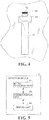
- Fig. 4 is a view for explaining the relationship between a component storage portion 41 for storing the component contained in the region 32 in Fig. 3 , a seat tag storage portion 42, and a plug-in detecting portion 43.
- the component storage portion 41 is one example of the first storage portion of claims.
- the component storage portion 41 is a recessed portion having a shape fit for the shape of the component.
- the component storage portion 41 has a shape in which the bolt is stored in the recessed portion of the component storage portion 41.
- the component may be stored into the component storage portion 41 in a state where an elastic member such as a sponge is fitted in the component storage portion 41.
- the seat tag storage portion 42 is one example of the second storage portion of claims.
- the seat tag storage portion 42 is a recessed portion provided in the vicinity of the component storage portion 41 and the later-described plug-in detecting portion 43.
- an IC tag T2 (seat tag, second IC tag) in which information for identifying the position of the serving tray 3 is recorded is embedded.
- the vicinity of the component storage portion 41 and the vicinity of the later-described plug-in detecting portion 43 mentioned after mean a range as follows. It is to say that, the detection device 4 inserted in the plug-in detecting portion 43 can detect IC tags in the range.
- IC-tags is embedded in the component such as the IC-tag-attached bolt, which is stored in the component storage portion 41, and the other of such IC-tags is stored in the seat tag strage portion 42.
- this range changes according to the output power of electromagnetic waves output from the detection device 4, but is preferred as it is closer to a (not-illustrated) loop coil antenna provided with the detection device 4 generally.
- the detection limit is about 5 mm.
- the space between the component storage portion 41 and the plug-in detecting portion 43 and the space between the plug-in detecting portion 43 and the seat tag storage portion 42 are each 0 mm or more and 10 mm or less, and most preferably set to 0 mm or more and about 5 mm or less, which is the detection limit.
- a state where the component storage portion 41 and the plug-in detecting portion 43 are integrated, a state where plug-in detecting portion 43 and the seat tag storage portion 42 are integrated, or a state where the component storage portion 41, the plug-in detecting portion 43, and the seat tag storage portion 42 are all integrated is made.
- the plug-in detecting portion 43 is one example of the third storage portion of claims.
- the plug-in detecting portion 43 is a recessed portion provided between the component storage portion 41 and the seat tag storage portion 42.
- the tip of the detection device 4 is inserted in the plug-in detecting portion 43, thereby making it possible to detect both the IC tag embedded in the component stored in the component storage portion 41 and the seat tag stored in the seat tag storage portion 42.
- the detection device 4 is one example of the detection device of claims.
- the detection device 4 is a device for detecting the IC tag (seat tag) indicating the component in the serving tray 3 and the position in the serving tray 3.
- Fig. 5 is a diagram illustrating a functional configuration of the detection device 4 illustrated in Fig. 1 .
- the detection device 4 includes an IC tag detection part 51, a communication unit 52, and a display unit 53.
- the detection device 4 in this example has these functions as one device, but does not always need to be configured as one device.
- only a display device may be another device, or the IC tag detection part 51 and the communication unit 52 may be configured in another device.
- the IC tag detection part 51 is one example of the acquisition part of claims.
- the IC tag detection part 51 can acquire a detection signal from the loop coil antenna (not illustrated) built in the tip and, based on the signal, acquire each identification information from the IC tag embedded in the component and the IC tag (seat tag) indicating the position in the serving tray 3.
- the communication unit 52 is one example of the transmission processing unit of claims.
- the communication unit 52 is a communication interface for the IC tag detection part 51 to exchange information with the component management server 2.
- the communication unit 52 is, for example, a Bluetooth (registered trademark) module, a Wifi module, another radio communication module, or the like.
- the communication unit 52 is not always able to communicate with the component management server 2 directly, and may be a USB interface, for example, and in this case, it may be designed so that a device that has directly communicated with the component management server 2 and the USB interface are connected to transmit/receive information therebetween.
- the display unit 53 displays the identification information read from the IC tag by the IC tag detection part 51, or information acquired from the identification information.
- the display unit 53 may be configured to display information transmitted from the component management server 2.
- Fig. 6A and Fig. 6B are views for explaining the detection device 4 and explaining a detection method
- Fig. 6A is one example of the IC tag detection part 51
- Fig. 6B is a view for explaining the method of simultaneously detecting the two IC tags by the IC tag detection part 51.
- the IC tag detection part 51 includes a long and narrow bar-shaped grip portion 54 and a plate-shaped tip portion 55. In the tip portion 55, the coil antenna (not illustrated) is built.
- the coil antenna not illustrated in Fig.
- the tip portion 55 is inserted in the plug-in detecting portion 43, thereby making it possible to detect both the IC tag T2 stored in the seat tag storage portion 42 and the IC tag embedded in the component stored in the component storage portion 41, which is not illustrated.
- Fig. 7 is an A-A cross-sectional view of Fig. 6 and its partial enlarged view.
- a component PI having an IC tag T1 is stored in the component storage portion 41 illustrated in Fig. 6
- the IC tag T2 is attached in the seat tag strage portion 42, and, in the above-mentioned state, the tip portion 55 of the IC tag detection part 51 of the detection device 4 is inserted in the plug-in detecting portion 43.
- the tip portion 55 of the IC tag detection part 51 of the detection device 4 is inserted in the plug-in detecting portion 43.
- the component PI having the IC tag T1 being a metal bolt
- a loop of magnetic lines of force of mutual induction does not enter the metal and is distributed in the space and a non-metal resin material.
- magnetic lines of force F are distributed in a state of avoiding the component PI, resulting that magnetic lines of force ⁇ become a closed loop of magnetic lines of force centered on the line L, which is a mutual induction between the IC tag T1 and the IC tag T2. That is, an antenna coil included in the IC tag T1 and an antenna coil included in the IC tag T2 are coupled by the loop of magnetic lines of force ⁇ in the mutual induction relationship, to thereby detect the information recorded in the IC tag T1 and the IC tag T2.
- an antenna coil surface (parallel to L, which is not illustrated) of the IC tag detection part 51, an antenna coil surface of the IC tag T1, and an antenna coil surface of the IC tag T2 are preferred to be parallel to one another.
- Fig. 8 is a flowchart for explaining the component management method. Incidentally, as a premise for the following processing, it is set that a worker has prepared the serving tray 3, and the part box 31 in which components to be stored in the serving tray 3 are stored and read IC tags by the detection device 4 to transmit information to the component management server 2.
- the worker stores a predetermined component in a predetermined place in the serving tray 3 while browsing a work instruction or the like. Then, the worker inserts the IC tag detection part 51 of the detection device 4 in the plug-in detecting portion 43 disposed near the place in which the component has been stored. As has been explained in Fig. 7 , this makes it possible to detect the two IC tags only by a one-time detection operation.
- Step S1 the communication processing unit 11 receives identification information of the component recorded in the IC tag embedded in the component and information for identifying the position in the serving tray 3, which is recorded in the IC tag embedded in the serving tray 3 in which the component has been stored.
- the information received at Step S1 are captured in the part information capturing unit 14 and the seat tag information capturing unit 15 respectively to be stored in the memory 13.
- Step S2 the judging unit 17 refers to the memory 13 (database) in which a position information on the serving tray 3 where the component has to be stored and the identification information of the component are associated with each other and judges whether the component is in a correct disposition relationship.
- the judging unit 17 advances the processing to Step S3
- the judging unit 17 advances the processing to Step S4.
- Step S3 as a result of the judgment at Step S2, it is judged that it is correct, and thus the tray information output unit 16 outputs the result and finishes the processing (END).
- an output destination may be a display that the component management server 2 includes, the display unit of the detection device that the worker uses, or another output destination.
- Step S4 as a result of the judgment at Step S2, it is judged that the disposition relationship is not correct, and thus the tray information output unit 16 outputs alert information and finishes the processing (END).
- the alert information based on the warning rule information 13E stored in the memory 13, the content of warning message may be changed or how to give a warning (for example, image blinking, a sound reminder, vibrations, or the like) may be controlled.
- the serving tray 3 includes: the component storage portion 41 (first storage portion) having a shape corresponding to the type of the bolt P1 (component) having the IC tag T1 (first IC tag); the IC tag T2 (second IC tag) in which the information for identifying the position on the serving tray 3 is recorded; and the seat tag storage portion 42 (second storage portion) accommodating the IC tag T2,
- the detection device 4 includes: the IC tag detection part 51 (acquisition part) that acquires the recorded information of the IC tag T1 embedded in the bolt PI and the recorded information of the IC tag T2; and the communication unit 52 (transmission processing unit) that transmits pieces of the recorded information acquired in the IC tag detection part 51 to the component management server 2
- the component management server 2 includes: the communication processing unit 11 (receiving unit) that receives the recorded information of the IC tag T1 and the recorded information of the IC tag T2 that are detected by the detection device 4; the memory 13 (database) in which the
- the disposition when the disposition is inappropriate, it is possible to output that the disposition is inappropriate, and when it is correct, it is possible to output that the disposition relationship is correct, and thus it is possible to securely dispose a plurality of types of screws or a component such as the bolt PI, which is likely to be mistaken by visual inspection, in a desired place in the serving tray.
- the information regarding the disposition place as well, the information can be acquired from the IC tag T2 stored in the seat tag storage portion 42 when reading the IC tag of the component, so that it is possible to securely recognize the positional relationship of the component and inform the worker of the positional relationship.
- the component management server 2 that performs management of components and the operation of the component management server (component management method) also include: similarly to the above-described component management system 1, the communication processing unit 11 (receiving unit) that receives the identification information of the component that is recorded in the first IC tag embedded in the component and the information for identifying the position in the serving tray 3, which is recorded in the second IC tag embedded in the serving tray 3 in which the component is stored; the memory 13 (database) in which the information of the position in the serving tray 3 in which the component has to be stored and the identification information of the component are associated with each other; the judging unit 17 (judging unit) that refers to the memory 13 based on pieces of the recorded information received in the communication processing unit 11 and judges whether or not the component is in a correct disposition relationship; and the tray information output unit 16 (output unit) that outputs the judgment result of the judging unit 17, and thus it is possible to exhibit the effects similar to those of the above-described component management system 1.
- the communication processing unit 11 receiving unit
- the memory 13
- the serving tray 3 in this example include: the component storage portion 41 (first storage portion) that corresponds to the shape of the bolt PI (component) having the IC tag T1 (first IC tag); the IC tag T2 (second IC tag) in which the information for identifying the position on the serving tray 3 is recorded; the seat tag storage portion 42 (second storage portion) for storing the IC tag T2 (second IC tag); and the plug-in detecting portion 43 (third storage portion) that establishes a disposition relationship that enables reading of both the IC tag T1 (first IC tag) embedded in the component stored in the component storage portion 41 and the IC tag T2 (second IC tag) stored in the seat tag storage portion 42 by a predetermined detection operation, and thus performing only a predetermined detection operation makes it possible to efficiently acquire pieces of information on specification and disposition of the component to be stored on the serving tray 3.
- the operation of the detection device 4 corresponding to the serving tray 3 in this example is to detect the first IC tag embedded in the component stored on the serving tray 3 and detect the second IC tag indicating the position on the serving tray 3, and the detection device 4 executes these detection steps by a predetermined detection operation, and thus performing only the predetermined detection operation makes it possible to efficiently acquire pieces of the information on specification and disposition of the component to be stored on the serving tray 3.
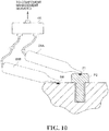
- a detection device 4A includes two IC tag detection parts 81A, 81B ( Fig. 10 ). Further, the seat tag is disposed not in the vicinity of the storage portion in which a component is to be stored, but in a predetermined region.
- Fig. 9 is a conceptual diagram for explaining one example of a serving tray 3A and a part box 61 according to the second embodiment of the present invention.
- the serving tray 3A illustrated in Fig. 9 has a region 62, a region 63, and a region 64 for storing therein components A-1, components A-2, and components A-n, which are stored in the part box 61, and in these regions, IC tags 62t, 63t, and 64t for identifying positions on the serving tray 3A and components 62a, 63a, 64a, and 64b are disposed.
- the serving tray 3A in an actual assembling drawing 65, there is drawn a step where the components 62a, 63a, 64a, and 64b that are stored in the region 62, the region 63, and the region 64 respectively are used.
- the serving tray 3A illustrated in Fig. 9 is in a state where all components necessary for each of the steps are not disposed.
- the region 62 is defined as a seat A-1 raw
- the region 63 is defined as a seat A-2 raw
- the region 64 is defined as a seat A-n raw, and it is designed so as to be able to clearly grasp in which step the component disposed in each of the regions is used.
- recessed portions 66, 67, and 68 in which, for example, a bar-shaped component, a bolt, and so on are inserted
- components to be used in a step 3 are disposed, on a projection 69 (onto which, for example, a washer or the like is fitted) in the seat A-2 raw
- the component 63a is disposed, which is easily grasped to be used in a step 1
- the component 64a is disposed, which is easily grasped to be used in a step 2.
- the assembling drawing 65 also clearly illustrates in which portion of which part each of the steps is used.
- Fig. 10 is a view illustrating one example of the detection device 4A and the IC tag detection parts 81A, 81B according to the second embodiment of the present invention.
- Fig. 11 is a view illustrating an example where an IC tag 72 of the component 64b is detected by the detection device 4A illustrated in Fig. 10 . As illustrated in Fig. 10 and Fig.
- the IC tag detection part 81A first IC tag detection part
- the IC tag detection part 81B second IC tag detection part
- the serving tray 3A in the second embodiment of the present invention has been explained.
- processing to improve consistency of the recessed portion for the detection part insertion is not required, where the recessed portion is for simultaneously detecting two IC tags and intensifying electromagnetic coupling, such as a tag center line for detection. Further, it is a method to use the two detection parts, and thus as compared to the serving tray 3, even when types of components are increased, the serving tray 3A can flexibly correspond to these changes.
- the serving trays 3, 3A to be drawn based on the logical tray information 13C Pieces of the recorded information of the IC tags in which pieces of information indicating the positions on the serving trays 3, 3A and the components are recorded are utilized, thereby making it possible to associate CAD data such as an assembling drawing of an article to be a working object with the position of the component each other in real time.
- CAD data such as an assembling drawing of an article to be a working object with the position of the component each other in real time.
- current progress or the like is displayed by updating an image, a video, or the like associated with the serving tray explained in Fig. 3 or Fig. 9 as needed, and thereby it is possible to easily grasp also the progress of the current work or the like visually.
- sample information of the serving tray 3 or 3A based on specifications, a work instruction, or the like.
Abstract
Description
- The present invention relates to a component management system, a component management server, a component management method, and a serving tray.
- At an assembling step of (when manufacturing and when maintaining and inspecting) railway vehicles, aircraft (railway vehicles and so on hereinafter), and so on, a fastening work is performed, in which a worker uses a torque wrench and tighten screws or the like until set torque so as to fasten respective component parts. There are various types of component parts of the railway vehicles and the like, and thus, clamping aspects that is objects of the fastening work, the diameter, the length, and the like of a shank of the screw are composed of various types of screw.
- For example, in an assembling process of an aircraft disclosed in
PTL 1, a worker carries a basket in which a plurality of types of screws, bolts, and the like required for fastening work are stored together beforehand. When taking an appropriate screw, bolt, and the like described in a work instruction out of the basket, the worker checks them visually to take them out of the basket. Therefore, if the worker takes out an inappropriate screw and fasten it, there is a possibility that problems such as loosening of the screw, bolt, or the like and insufficient strength occur afterwards. From a viewpoint of preventing such problems, informing the worker of the error or the like has been performed from a system side. - {PTL 1}
JP 4949417B - In the management system for taking out screw described in
PTL 1, a proximity sensor, a photoelectric switch, or a weight sensor is attached to an accommodating portion for screws to judge the presence or absence of a screw. Then, whether or not taking out of the screw is incorrect is determined based on the state of presence or absence of the screw. Further, in another embodiment described inPTL 1, it is designed that a wireless IC tag is attached to a screw itself and the presence or absence of the screw is detected by an IC tag reader. - However, there are the following problems even in these methods. First, it is described that elastic material capable of holding screws by elastic restoration force is used for the accommodating portion disclosed in
PTL 1. Therefore, even though the accommodating portion of a storage case has a dedicated shape corresponding to the type of the screw, since the material of the accommodating portion is an elastic material, if the other screw has a shape similar to the shape of the accommodating portion, there is a possibility that the accommodating portion mistakenly accommodates the other screw. Further, even when such an event occurs, in the above-described method, since judgment is made only based on the presence or absence of parts accommodation, it is difficult for the system side to detect the error. - Further, even in the method in which the wireless IC tag disclosed in
PTL 1 is attached to a screw and the presence or absence of the screw is detected and recognized by the IC tag reader, it is difficult for the system side to concretely specify at which position of the accommodating portion in the basket the screw having the wireless IC tag is accommodated. - The present invention has been made in consideration of at least one of the above-described problems, and an object thereof is to provide a component management system, a component management server, a component management method, and a serving tray, thereby being able to dispose a plurality of types of components at desired places in the serving tray, securely recognize a disposed position and a positional relationship between the place where the components are disposed, and inform them.
- In order to solve the above-described problems, a first aspect of the present invention relates to a component management system. That is, the component management system of the present invention is a component management system including: a portable serving tray in which a plurality of types of components are stored; a detection device that detects identification information of the components stored in the serving tray; and a component management server that receives the identification information detected by the detection device and performs management of the components, in which the serving tray includes: a first storage portion having a shape corresponding to a type of the component having a first IC tag; a second IC tag in which information for identifying a position on the serving tray is recorded; and a second storage portion that stores the second IC tag, the detection device includes: an acquisition part that acquires recorded information of the first IC tag and recorded information of the second IC tag; and a transmission processing unit that transmits pieces of the recorded information acquired in the acquisition part to the component management server, and the component management server includes: a receiving unit that receives the recorded information of the first IC tag and the recorded information of the second IC tag that are detected by the detection device; a database in which information of a position on the serving tray in which the component has to be stored and the identification information of the component are associated with each other; a judging unit that refers to the database on the bases of pieces of the recorded information received in the receiving unit and judges whether or not the component is in a correct disposition relationship; and an output unit that outputs a judgment result of the judging unit.
- Further, a second aspect of the present invention relates to a component management server. That is, the component management server of the present invention includes: a receiving unit that receives identification information of a component that is recorded in a first IC tag embedded in the component and information for identifying a position on a serving tray, the information being recorded in a second IC tag embedded in the serving tray in which the component is stored; a database in which information of a position in the serving tray in which the component has to be stored and the identification information of the component are associated with each other; a judging unit that refers to the database on the bases of pieces of the information received in the receiving unit and judges whether or not the component is in a correct disposition relationship; and an output unit that outputs a judgment result of the judging unit.
- Further, a third aspect of the present invention relates to a component management method. That is, the component management method of the present invention is a component management method executed by a component management server that includes a receiving unit, a judging unit, and an output unit and performs management of components, the component management method including: a reception step of the receiving unit which receives identification information of the component recorded in a first IC tag embedded in the component and information for identifying a position on a serving tray, the information being recorded in a second IC tag embedded in the serving tray in which the component is stored; a judging step of the judging unit which refers to a database in which information of a position on the serving tray in which the component has to be stored and the identification information of the component are associated with each other, which are based on pieces of the information received in the reception step, and judges whether the component is in a correct disposition relationship; and an output step of the output unit which outputs a judgment result of the judging step.
- Further, a fourth aspect of the present invention relates to a serving tray. That is, the serving tray of the present invention includes: a first storage portion that corresponds to a shape of a component having a first IC tag; a second IC tag in which information for identifying a position on the serving tray is recorded; a second storage portion for storing the second IC tag; and a third storage portion which establishes a disposition relationship capable of reading both the first IC tag stored in the component accommodated in the first storage portion and the second IC tag stored in the second storage portion , the reading being a predetermined detection operation.
- Further, a component management method according to another aspect of the present invention is a component management method that is used when a component is stored on a serving tray and is executed by a detection device including a detection part capable of detecting an IC tag, the component management method including: a first detection step of detecting a first IC tag embedded in a component stored on the serving tray; and a second detection step of detecting a second IC tag indicating a position on the serving tray, in which the detection device executes the first detection step and the second detection step by a predetermined detection operation.
- Further, the component management method of the present invention, in which preferably, the predetermined detection operation is an operation in which an IC tag detection part of the detection device is inserted in a storage portion one time, the storage portion provided between a position of the first IC tag and a position of the second IC tag on the serving tray, in addition to the above-described constitution.
- Further, the component management method of the present invention, in which preferably, the detection device includes: a first IC tag detection part and a second IC tag detection part, and the predetermined detection operation is an operation in which the second IC tag detection part reads the second IC tag while the first IC tag detection part reading the first IC tag, in addition to the above-described constitution.
- According to the present invention, it is possible to provide a component management system, a component management server, a component management method, and a serving tray, which are able to dispose a plurality of types of components at desired places on the serving tray, securely grasp a disposed position and a positional relationship between the place where the components are disposed, and inform them.
-
- {
Fig. 1} Fig. 1 is a diagram illustrating a schematic constitution of a component management system according to a first embodiment of the present invention. - {
Fig. 2} Fig. 2 is a diagram illustrating a schematic configuration of a component management server illustrated inFig. 1 . - {
Fig. 3} Fig. 3 is a conceptual diagram for explaining one example of a serving tray and a part box illustrated inFig. 1 . - {
Fig. 4} Fig. 4 is a view for explaining the relationship between acomponent storage portion 41 for storing a component contained in a region inFig. 3 , a seat tag storage portion, and a plug-in portion for detection. - {
Fig. 5} Fig. 5 is a diagram illustrating a functional configuration of a detection device illustrated inFig. 1 . - {
Fig. 6A and Fig. 6B} Fig. 6A and Fig. 6B are views for explaining the detection device and a detection method,Fig. 6A is one example of an IC tag detection part, andFig. 6B is a view for explaining the method of simultaneously detecting two IC tags by the IC tag detection part. - {
Fig. 7} FIG. 7 is a cross-sectional view taken along the line A-A illustrated inFIG. 5 and a partially enlarged view, where a tip portion of the IC tag detection part of the detection device is inserted in the plug-in portion for detection in a state where an IC-tag-attached bolt having an IC tag is accommodated to the component strage portion illustrated inFig. 5 and an IC tag is accommodated in the seat tag strage portion. - {
Fig. 8} Fig. 8 is a flowchart for explaining a component management method. - {
Fig. 9} Fig. 9 is a diagram illustrating one example of a serving tray according to a second embodiment of the present invention. - {
Fig. 10} Fig. 10 is a diagram illustrating one example of adetection device 4A according to the second embodiment of the present invention. - {
Fig. 11} Fig. 11 is a diagram illustrating a detection example of a component and a seat tag by the detection device illustrated inFig. 10 . - Hereinafter, embodiments of the present invention will be explained with reference to the attached drawings. Incidentally, the component management system, the component management server, the component management method, and the serving tray of the present invention are not limited to the following embodiments.
-
Fig. 1 is a diagram illustrating a schematic constitution of acomponent management system 1 according to a first embodiment of the present invention. Thiscomponent management system 1 includes acomponent management server 2, aserving tray 3, and adetection device 4. Incidentally, thecomponent management server 2 and thedetection device 4 are constituted so as to be able to communicate with each other via a wired or wireless communication network (not illustrated), and theserving tray 3 and thedetection device 4 are constituted so as to be able to communicate with each other via a wired or wireless communication network (not illustrated). - The
component management server 2 is one example of the component management server of claims. Thecomponent management server 2 is a server for performing management of components such as bolts and screws that are served on theserving tray 3. Incidentally, thecomponent management server 2 is what is called a server computer and includes, for example, a CPU (Central Processing Unit), a RAM (Random Access Memory), a ROM (Read Only Memory), a HDD (Hard Disk Drive), a communication interface, and so on, and the CPU reads programs stored in the ROM, the HDD, and the like in the RAM to execute them, thereby making it possible to perform later-described respective functions that the server has. Incidentally, a hardware configuration of thecomponent management server 2 is not limited to the above-described configuration, and can be changed appropriately. For example, thecomponent management server 2 may be configured to include a SSD (Flash Solid State Drive) in place of the HDD, or in addition to the HDD. Further, as the hardware configuration of thecomponent management server 2, in addition to the above-described configuration, thecomponent management server 2 may include output means such as a display and a speaker and input means such as a mouse, a keyboard, and a tablet. -
Fig. 2 is a diagram illustrating a schematic configuration of thecomponent management server 2 illustrated inFig. 1 . Thecomponent management server 2 includes acommunication processing unit 11, a componentmanagement control unit 12, and amemory 13. - The
communication processing unit 11 is one example of the receiving unit and the output unit of claims. Thecommunication processing unit 11 is an interface for communicating with an external device by wire or wireless. - The component
management control unit 12 includes a partinformation capturing unit 14, a seat taginformation capturing unit 15, a trayinformation output unit 16, a judgingunit 17, and analert setting unit 18. - The part
information capturing unit 14 performs processing to capture information on a component that has to be disposed on the servingtray 3. For example, when a worker uses thedetection device 4 to read recorded information from an IC tag (first IC tag) embedded in the component, the recorded information is transmitted to the partinformation capturing unit 14 and the partinformation capturing unit 14stores part information 13A in thememory 13. The worker in this example performs a work to pick up each components from a later-describedpart box 31 to attach it on the servingtray 3. In this case, the recorded information of the IC tag embedded in each the components, which is read by thedetection device 4, is transmitted to the partinformation capturing unit 14. - The seat tag
information capturing unit 15 performs processing to capture information on a position on the servingtray 3. For example, when the worker uses thedetection device 4 to read position information from an IC tag (second IC tag, to be sometimes referred to as a seat tag, hereinafter) already embedded in the vicinity of a part storage portion in the servingtray 3, the position information is transmitted to the seat taginformation capturing unit 15 and the seat taginformation capturing unit 15 storesseat tag information 13B in thememory 13. The worker in this example performs a work to take each components out of the servingtray 3. In this case, the position information read by thedetection device 4 is transmitted to the seat taginformation capturing unit 15. - The tray
information output unit 16 outputs information on the components and information on the positions on the servingtray 3 based on thepart information 13A captured in the partinformation capturing unit 14 and theseat tag information 13B captured in the seat taginformation capturing unit 15. Further, the trayinformation output unit 16 can also outputlogical tray information 13C andsample tray information 13D, which will be described later. Further, the trayinformation output unit 16 can also output a judgment result of the later-describedjudging unit 17. - The judging
unit 17 refers to the memory 13 (database) based on the recorded information received in thecommunication processing unit 11 to judge whether the component and the position of the component on the servingtray 3 are in a correct disposition relationship. Incidentally, the judgment result of the judgingunit 17 is supplied to the trayinformation output unit 16. - The
alert setting unit 18, based on later-describedwarning rule information 13E, can inform the worker of the disposition on the servingtray 3 and whether the taken-out part itself is correct or false. - In the
memory 13, thepart information 13A, theseat tag information 13B, thelogical tray information 13C, thesample tray information 13D, thewarning rule information 13E, and so on are stored. Incidentally, thememory 13 may be built as an integrated database that enables searching, adding, deleting, changing, and the like of these pieces of information. - The
part information 13A is, in the case of the component being a hexagon head bolt, for example, identification information of an IC tag embedded in the hexagon head bolt, a name of equipment to which the hexagon head bolt is attached, a bolt size, a bolt length under head, a bolt material, tightening torque, the number of bolts, and so on. - The
seat tag information 13B is, for example, identification information of an IC tag disposed in the servingtray 3, information indicating the position on the servingtray 3, and so on. Incidentally, thelogical tray information 13C and thesample tray information 13D will be described later. - The serving
tray 3 is one example of the serving tray of claims. The servingtray 3, in which for example, components such as a plurality of types of screws and bolts, which are used at an assembling step of a railway vehicle, are stored, is a tray for serving the components to a work site. Incidentally, the servingtray 3 is made of resin, and so on, for example. - Incidentally, the component in this embodiment is an IC-tag-attached bolt in which an IC tag is embedded in a bolt head, for example. As for the IC-tag-attached bolt, some types of bolt with an IC-tag are designed so that a high-frequency current such as a standing wave, which is different from an eddy current, flows on the metal surface of the bolt when high-frequency electromagnetic wave in an UHF band is irradiated to the metal surface, and the bolt is detected with high sensitivity. And, in the case where the detector can be brought sufficiently closely to the IC-tag, it is not necessary to form a projection portion by accommodating the IC tag to the bolt in three dimensions, where the IC tag is perpendicular to the metal surface of the bolt so that such high-frequency current flows easily. By the way, in the case where the detector is brought sufficiently close to the IC tag to be able to overcome detection prevention and repulsion of the eddy current, it is possible to simply dispose the IC tag on the metal surface of the bolt so as to make a coil antenna surface (not illustrated) inside the IC tag parallel to the metal surface of the bolt, resulting in that a formation to eliminate the projection portion is enabled when attaching the IC tag.
-
Fig. 3 is a conceptual diagram for explaining one example of the servingtray 3 illustrated inFig. 1 and thepart box 31. The servingtray 3 illustrated inFig. 3 has aregion 32, aregion 33, and aregion 34 for storing components A-1, components A-2, and components A-n, which are stored in theparts box 31, respectively. Further, in the servingtray 3, an actual assembling drawing 35 and steps of the use of the components stored in theregion 32, theregion 33, and theregion 34 are drawn. - In the serving
tray 3, theregion 32 is defined as a seat A-1 raw, theregion 33 is defined as a seat A-2 raw, and theregion 34 is defined as a seat A-n raw, and they are described clearly. Further, components to be used in astep 3 are accommodated in recessed portions in the seat A-1 raw, and it is clearly expressed that acomponent 33a and a component 33b embedded in the seat A-2 raw are used in astep 1, and acomponent 34a and a component 34b embedded in the seat A-n raw are used in astep 2. Further, in the assembling drawing 35, a portion and a place to which the steps is to be used is also clearly expressed . Incidentally, the example illustrated inFig. 3 illustrates a state where only thecomponents -
Fig. 4 is a view for explaining the relationship between acomponent storage portion 41 for storing the component contained in theregion 32 inFig. 3 , a seattag storage portion 42, and a plug-in detectingportion 43. - The
component storage portion 41 is one example of the first storage portion of claims. Thecomponent storage portion 41 is a recessed portion having a shape fit for the shape of the component. For example, in the case of the component being a bolt, thecomponent storage portion 41 has a shape in which the bolt is stored in the recessed portion of thecomponent storage portion 41. Incidentally, the component may be stored into thecomponent storage portion 41 in a state where an elastic member such as a sponge is fitted in thecomponent storage portion 41. - The seat
tag storage portion 42 is one example of the second storage portion of claims. The seattag storage portion 42 is a recessed portion provided in the vicinity of thecomponent storage portion 41 and the later-described plug-in detectingportion 43. In the seattag storage portion 42, an IC tag T2 (seat tag, second IC tag) in which information for identifying the position of the servingtray 3 is recorded is embedded. Incidentally, the vicinity of thecomponent storage portion 41 and the vicinity of the later-described plug-in detectingportion 43 mentioned after mean a range as follows. It is to say that, thedetection device 4 inserted in the plug-in detectingportion 43 can detect IC tags in the range. One of such IC-tags is embedded in the component such as the IC-tag-attached bolt, which is stored in thecomponent storage portion 41, and the other of such IC-tags is stored in the seattag strage portion 42. Of course, this range changes according to the output power of electromagnetic waves output from thedetection device 4, but is preferred as it is closer to a (not-illustrated) loop coil antenna provided with thedetection device 4 generally. For example, in the case where the electromagnetic wave is set to electromagnetic waves in a UHF band of 920 MHz and the IC tag is set to the type IM5-PK2525 manufactured by Hitachi Chemical Company, Ltd., the detection limit is about 5 mm. In this case, the space between thecomponent storage portion 41 and the plug-in detectingportion 43 and the space between the plug-in detectingportion 43 and the seattag storage portion 42 are each 0 mm or more and 10 mm or less, and most preferably set to 0 mm or more and about 5 mm or less, which is the detection limit. Incidentally, in the case where each space between the storage portions is 0 mm, a state where thecomponent storage portion 41 and the plug-in detectingportion 43 are integrated, a state where plug-in detectingportion 43 and the seattag storage portion 42 are integrated, or a state where thecomponent storage portion 41, the plug-in detectingportion 43, and the seattag storage portion 42 are all integrated is made. - The plug-in detecting
portion 43 is one example of the third storage portion of claims. The plug-in detectingportion 43 is a recessed portion provided between thecomponent storage portion 41 and the seattag storage portion 42. The tip of thedetection device 4 is inserted in the plug-in detectingportion 43, thereby making it possible to detect both the IC tag embedded in the component stored in thecomponent storage portion 41 and the seat tag stored in the seattag storage portion 42. - The
detection device 4 is one example of the detection device of claims. Thedetection device 4 is a device for detecting the IC tag (seat tag) indicating the component in the servingtray 3 and the position in the servingtray 3.Fig. 5 is a diagram illustrating a functional configuration of thedetection device 4 illustrated inFig. 1 . As illustrated inFig. 5 , thedetection device 4 includes an ICtag detection part 51, acommunication unit 52, and adisplay unit 53. Incidentally, thedetection device 4 in this example has these functions as one device, but does not always need to be configured as one device. For example, only a display device may be another device, or the ICtag detection part 51 and thecommunication unit 52 may be configured in another device. - The IC
tag detection part 51 is one example of the acquisition part of claims. The ICtag detection part 51 can acquire a detection signal from the loop coil antenna (not illustrated) built in the tip and, based on the signal, acquire each identification information from the IC tag embedded in the component and the IC tag (seat tag) indicating the position in the servingtray 3. - The
communication unit 52 is one example of the transmission processing unit of claims. Thecommunication unit 52 is a communication interface for the ICtag detection part 51 to exchange information with thecomponent management server 2. Thecommunication unit 52 is, for example, a Bluetooth (registered trademark) module, a Wifi module, another radio communication module, or the like. Incidentally, thecommunication unit 52 is not always able to communicate with thecomponent management server 2 directly, and may be a USB interface, for example, and in this case, it may be designed so that a device that has directly communicated with thecomponent management server 2 and the USB interface are connected to transmit/receive information therebetween. - The
display unit 53 displays the identification information read from the IC tag by the ICtag detection part 51, or information acquired from the identification information. Incidentally, thedisplay unit 53 may be configured to display information transmitted from thecomponent management server 2. -
Fig. 6A and Fig. 6B are views for explaining thedetection device 4 and explaining a detection method, andFig. 6A is one example of the ICtag detection part 51, andFig. 6B is a view for explaining the method of simultaneously detecting the two IC tags by the ICtag detection part 51. As illustrated inFig. 6A , the ICtag detection part 51 includes a long and narrow bar-shapedgrip portion 54 and a plate-shapedtip portion 55. In thetip portion 55, the coil antenna (not illustrated) is built. As illustrated inFig. 6B , thetip portion 55 is inserted in the plug-in detectingportion 43, thereby making it possible to detect both the IC tag T2 stored in the seattag storage portion 42 and the IC tag embedded in the component stored in thecomponent storage portion 41, which is not illustrated. -
Fig. 7 is an A-A cross-sectional view ofFig. 6 and its partial enlarged view. InFig 7 , a component PI having an IC tag T1 is stored in thecomponent storage portion 41 illustrated inFig. 6 , the IC tag T2 is attached in the seattag strage portion 42, and, in the above-mentioned state, thetip portion 55 of the ICtag detection part 51 of thedetection device 4 is inserted in the plug-in detectingportion 43. As illustrated in the enlarged view ofFig. 7 , in the case of the component PI having the IC tag T1 being a metal bolt, a loop of magnetic lines of force of mutual induction does not enter the metal and is distributed in the space and a non-metal resin material. That is, magnetic lines of force F are distributed in a state of avoiding the component PI, resulting that magnetic lines of force Φ become a closed loop of magnetic lines of force centered on the line L, which is a mutual induction between the IC tag T1 and the IC tag T2. That is, an antenna coil included in the IC tag T1 and an antenna coil included in the IC tag T2 are coupled by the loop of magnetic lines of force Φ in the mutual induction relationship, to thereby detect the information recorded in the IC tag T1 and the IC tag T2. Incidentally, an antenna coil surface (parallel to L, which is not illustrated) of the ICtag detection part 51, an antenna coil surface of the IC tag T1, and an antenna coil surface of the IC tag T2 are preferred to be parallel to one another. However, the angel rang of the coil surfaces may be a range from parallel (θ = 0° or 180°) to an angle other than orthogonal (θ = 90°) as long as it has a sharing part of magnetic force line Φ. - Then, there will be explained the component management method to be executed by the
component management server 2. The following processing is processing to be performed when the components are stored.Fig. 8 is a flowchart for explaining the component management method. Incidentally, as a premise for the following processing, it is set that a worker has prepared the servingtray 3, and thepart box 31 in which components to be stored in the servingtray 3 are stored and read IC tags by thedetection device 4 to transmit information to thecomponent management server 2. - The worker stores a predetermined component in a predetermined place in the serving
tray 3 while browsing a work instruction or the like. Then, the worker inserts the ICtag detection part 51 of thedetection device 4 in the plug-in detectingportion 43 disposed near the place in which the component has been stored. As has been explained inFig. 7 , this makes it possible to detect the two IC tags only by a one-time detection operation. - Step S1: the
communication processing unit 11 receives identification information of the component recorded in the IC tag embedded in the component and information for identifying the position in the servingtray 3, which is recorded in the IC tag embedded in the servingtray 3 in which the component has been stored. In thecomponent management server 2, the information received at Step S1 are captured in the partinformation capturing unit 14 and the seat taginformation capturing unit 15 respectively to be stored in thememory 13. - Step S2: the judging
unit 17 refers to the memory 13 (database) in which a position information on the servingtray 3 where the component has to be stored and the identification information of the component are associated with each other and judges whether the component is in a correct disposition relationship. When the disposition relationship is correct, the judgingunit 17 advances the processing to Step S3, and when the disposition relationship is not correct, the judgingunit 17 advances the processing to Step S4. - Step S3: as a result of the judgment at Step S2, it is judged that it is correct, and thus the tray
information output unit 16 outputs the result and finishes the processing (END). Incidentally, an output destination may be a display that thecomponent management server 2 includes, the display unit of the detection device that the worker uses, or another output destination. - Step S4: as a result of the judgment at Step S2, it is judged that the disposition relationship is not correct, and thus the tray
information output unit 16 outputs alert information and finishes the processing (END). Incidentally, as for the alert information, based on thewarning rule information 13E stored in thememory 13, the content of warning message may be changed or how to give a warning (for example, image blinking, a sound reminder, vibrations, or the like) may be controlled. - As above, according to the component management system 1 of the first embodiment, the serving tray 3 includes: the component storage portion 41 (first storage portion) having a shape corresponding to the type of the bolt P1 (component) having the IC tag T1 (first IC tag); the IC tag T2 (second IC tag) in which the information for identifying the position on the serving tray 3 is recorded; and the seat tag storage portion 42 (second storage portion) accommodating the IC tag T2, the detection device 4 includes: the IC tag detection part 51 (acquisition part) that acquires the recorded information of the IC tag T1 embedded in the bolt PI and the recorded information of the IC tag T2; and the communication unit 52 (transmission processing unit) that transmits pieces of the recorded information acquired in the IC tag detection part 51 to the component management server 2, and the component management server 2 includes: the communication processing unit 11 (receiving unit) that receives the recorded information of the IC tag T1 and the recorded information of the IC tag T2 that are detected by the detection device 4; the memory 13 (database) in which the information of the position on the serving tray 3 and the identification information of the component are associated with each other , the component being stored on the serving tray; the judging unit 17 (judging unit) that refers to the memory 13 based on pieces of the recorded information received in the communication processing unit 11 and judges whether the bolt P1 is in a correct disposition relationship; and the tray information output unit 16 (output unit) that outputs the judgment result of the judging unit 17, and thus it is possible to judge which component is disposed in the serving tray 3 and whether it is correct and output a result. That is, when the disposition is inappropriate, it is possible to output that the disposition is inappropriate, and when it is correct, it is possible to output that the disposition relationship is correct, and thus it is possible to securely dispose a plurality of types of screws or a component such as the bolt PI, which is likely to be mistaken by visual inspection, in a desired place in the serving tray. Further, as for the information regarding the disposition place as well, the information can be acquired from the IC tag T2 stored in the seat
tag storage portion 42 when reading the IC tag of the component, so that it is possible to securely recognize the positional relationship of the component and inform the worker of the positional relationship. - Further, the
component management server 2 that performs management of components and the operation of the component management server (component management method) also include: similarly to the above-describedcomponent management system 1, the communication processing unit 11 (receiving unit) that receives the identification information of the component that is recorded in the first IC tag embedded in the component and the information for identifying the position in the servingtray 3, which is recorded in the second IC tag embedded in the servingtray 3 in which the component is stored; the memory 13 (database) in which the information of the position in the servingtray 3 in which the component has to be stored and the identification information of the component are associated with each other; the judging unit 17 (judging unit) that refers to thememory 13 based on pieces of the recorded information received in thecommunication processing unit 11 and judges whether or not the component is in a correct disposition relationship; and the tray information output unit 16 (output unit) that outputs the judgment result of the judgingunit 17, and thus it is possible to exhibit the effects similar to those of the above-describedcomponent management system 1. - Further, the serving
tray 3 in this example include: the component storage portion 41 (first storage portion) that corresponds to the shape of the bolt PI (component) having the IC tag T1 (first IC tag); the IC tag T2 (second IC tag) in which the information for identifying the position on the servingtray 3 is recorded; the seat tag storage portion 42 (second storage portion) for storing the IC tag T2 (second IC tag); and the plug-in detecting portion 43 (third storage portion) that establishes a disposition relationship that enables reading of both the IC tag T1 (first IC tag) embedded in the component stored in thecomponent storage portion 41 and the IC tag T2 (second IC tag) stored in the seattag storage portion 42 by a predetermined detection operation, and thus performing only a predetermined detection operation makes it possible to efficiently acquire pieces of information on specification and disposition of the component to be stored on the servingtray 3. - Further, the operation of the
detection device 4 corresponding to the servingtray 3 in this example is to detect the first IC tag embedded in the component stored on the servingtray 3 and detect the second IC tag indicating the position on the servingtray 3, and thedetection device 4 executes these detection steps by a predetermined detection operation, and thus performing only the predetermined detection operation makes it possible to efficiently acquire pieces of the information on specification and disposition of the component to be stored on the servingtray 3. - Next, there will be explained a second embodiment of the present invention. In the second embodiment, the configuration of a reader and writer part in the
detection device 4 and the method of disposing the seat tag are different from those in the above-described first embodiment. Concretely, adetection device 4A includes two ICtag detection parts Fig. 10 ). Further, the seat tag is disposed not in the vicinity of the storage portion in which a component is to be stored, but in a predetermined region. -
Fig. 9 is a conceptual diagram for explaining one example of a servingtray 3A and apart box 61 according to the second embodiment of the present invention. The servingtray 3A illustrated inFig. 9 has aregion 62, aregion 63, and aregion 64 for storing therein components A-1, components A-2, and components A-n, which are stored in thepart box 61, and in these regions, IC tags 62t, 63t, and 64t for identifying positions on the servingtray 3A andcomponents tray 3A, in an actual assembling drawing 65, there is drawn a step where thecomponents region 62, theregion 63, and theregion 64 respectively are used. Incidentally, the servingtray 3A illustrated inFig. 9 is in a state where all components necessary for each of the steps are not disposed. - In the serving
tray 3A, theregion 62 is defined as a seat A-1 raw, theregion 63 is defined as a seat A-2 raw, and theregion 64 is defined as a seat A-n raw, and it is designed so as to be able to clearly grasp in which step the component disposed in each of the regions is used. That is, it is constituted that in recessedportions component 63a is disposed, which is easily grasped to be used in astep 1, and in a not-illustrated recessed portion disposed in the seat A-n raw, thecomponent 64a is disposed, which is easily grasped to be used in astep 2. Further, the assembling drawing 65 also clearly illustrates in which portion of which part each of the steps is used. - Incidentally, in the serving
tray 3A, unlike the servingtray 3 illustrated inFig. 3 , disposition of the IC tag indicating the position is not provided for each component, but the IC tags 62t, 63t, and 64t are embedded respectively in recessed portions 62o, 63o, and 64o provided in theregions Fig. 10 is a view illustrating one example of thedetection device 4A and the ICtag detection parts Fig. 11 is a view illustrating an example where anIC tag 72 of thecomponent 64b is detected by thedetection device 4A illustrated inFig. 10 . As illustrated inFig. 10 andFig. 11 , in this example, while the ICtag detection part 81A (first IC tag detection part) reading theIC tag 72 embedded in thecomponent 64b, the ICtag detection part 81B (second IC tag detection part) reads theIC tag 64t indicating the position on the servingtray 3A. - As above, the serving
tray 3A in the second embodiment of the present invention has been explained. In the servingtray 3A, unlike the servingtray 3, processing to improve consistency of the recessed portion for the detection part insertion is not required, where the recessed portion is for simultaneously detecting two IC tags and intensifying electromagnetic coupling, such as a tag center line for detection. Further, it is a method to use the two detection parts, and thus as compared to the servingtray 3, even when types of components are increased, the servingtray 3A can flexibly correspond to these changes. - Subsequently, there will be explained the serving
trays logical tray information 13C. Pieces of the recorded information of the IC tags in which pieces of information indicating the positions on the servingtrays detection device Fig. 3 orFig. 9 as needed, and thereby it is possible to easily grasp also the progress of the current work or the like visually. - Further, it is also possible to present sample information of the serving
tray - 1: component management system, 2: component management server, 3, 3A: serving tray, 4, 4A: detection device, 11: communication processing unit, 12: component management control unit, 13: memory, 14: part information capturing unit, 15: seat tag information capturing unit, 16: tray information output unit, 17: judging unit, 18: alert setting unit, 31: part box, 41: component storage portion, 42: seat tag embedded portion, 43: plug-in detecting portion, 51: IC tag detection part, 52: communication unit, 53: display unit, 54: grip portion, 55: tip portion, 61: part box, 81A, 81B: IC tag detection part
Claims (7)
- A component management system comprising: a portable serving tray in which a plurality of types of components are stored; a detection device that detects identification information of the components stored in the serving tray; and a component management server that receives the identification information detected by the detection device and performs management of the components, wherein
the serving tray includes:a first storage portion having a shape corresponding to a type of the component having a first IC tag;a second 1C tag in which information for identifying a position on the serving tray is recorded; anda second storage portion that stores the second IC tag,the detection device includes:an acquisition part that acquires recorded information of the first IC tag and recorded information of the second IC tag; anda transmission processing unit that transmits pieces of the recorded information acquired in the acquisition part to the component management server, andthe component management server includes:a receiving unit that receives the recorded information of the first IC tag and the recorded information of the second IC tag that are detected by the detection device;a database in which information of a position on the serving tray in which the component has to be stored and the identification information of the component are associated with each other;a judging unit that refers to the database on the bases of pieces of the recorded information received in the receiving unit and judges whether or not the component is in a correct disposition relationship; andan output unit that outputs a judgment result of the judging unit. - A component management server that performs management of components, the component management server comprising:a receiving unit that receives identification information of the component that is recorded in a first IC tag embedded in the component and information for identifying a position on a serving tray, the information being recorded in a second IC tag embedded in the serving tray in which the component is stored;a database in which information of a position in the serving tray in which the component has to be stored and the identification information of the component are associated with each other;a judging unit that refers to the database on the bases of pieces of the information received in the receiving unit and judges whether or not the component is in a correct disposition relationship; andan output unit that outputs a judgment result of the judging unit.
- A component management method executed by a component management server that includes a receiving unit, a judging unit, and an output unit and performs management of components, the component management method comprising:a reception step of the receiving unit which receives identification information of the component recorded in a first IC tag embedded in the component and information for identifying a position on a serving tray, the information being recorded in a second IC tag embedded in the serving tray in which the component is stored;a judging step of the judging unit which refers to a database in which information of a position on the serving tray in which the component has to be stored and the identification information of the component are associated with each other, which are based on pieces of the information received in the reception step, and judges whether the component is in a correct disposition relationship; andan output step of the output unit which outputs a judgment result of the judging step.
- A serving tray, comprising:a first storage portion that corresponds to a shape of a component having a first IC tag;a second IC tag in which information for identifying a position on the serving tray is recorded;a second storage portion for storing the second IC tag; anda third storage portion which establishes a disposition relationship capable of reading both the first IC tag stored in the component accommodated in the first storage portion and the second IC tag stored in the second storage portion , the reading being in a predetermined detection operation.
- A component management method that is used when a component is stored on a serving tray and is executed by a detection device including a detection part capable of detecting an IC tag, the component management method comprising:a first detection step of detecting a first IC tag embedded in a component stored on the serving tray; anda second detection step of detecting a second IC tag indicating a position on the serving tray, whereinthe detection device executes the first detection step and the second detection step by a predetermined detection operation.
- The component management method according to claim 5, wherein
the predetermined detection operation is an operation in which an IC tag detection part of the detection device is inserted in a storage portion one time, the storage portion provided between a position of the first IC tag and a position of the second IC tag on the serving tray. - The component management method according to claim 5, wherein
the detection device includes: a first IC tag detection part and a second IC tag detection part, and
the predetermined detection operation is an operation in which the second IC tag detection part reads the second IC tag while the first IC tag detection part reading the first IC tag.
Applications Claiming Priority (1)
| Application Number | Priority Date | Filing Date | Title |
|---|---|---|---|
| PCT/JP2016/056128 WO2017149621A1 (en) | 2016-02-29 | 2016-02-29 | Component management system, component management server, component management method, and serving tray |
Publications (3)
| Publication Number | Publication Date |
|---|---|
| EP3425463A1 true EP3425463A1 (en) | 2019-01-09 |
| EP3425463A4 EP3425463A4 (en) | 2019-10-23 |
| EP3425463B1 EP3425463B1 (en) | 2023-07-12 |
Family
ID=59742926
Family Applications (1)
| Application Number | Title | Priority Date | Filing Date |
|---|---|---|---|
| EP16892466.0A Active EP3425463B1 (en) | 2016-02-29 | 2016-02-29 | Component management system, component management server, component management method, and serving tray |
Country Status (3)
| Country | Link |
|---|---|
| EP (1) | EP3425463B1 (en) |
| JP (1) | JP6620218B2 (en) |
| WO (1) | WO2017149621A1 (en) |
Family Cites Families (9)
| Publication number | Priority date | Publication date | Assignee | Title |
|---|---|---|---|---|
| JPH0730255Y2 (en) * | 1989-10-23 | 1995-07-12 | 本田技研工業株式会社 | Parts supply container |
| EP1783570A1 (en) * | 2005-11-03 | 2007-05-09 | Snap-on Incorporated | Tool monitoring system |
| JP2008090453A (en) * | 2006-09-29 | 2008-04-17 | Sato Corp | Management system and management method for parts |
| US7557709B2 (en) * | 2006-10-13 | 2009-07-07 | RFID Mexico, S.A. DE C.V. | Item tracking system |
| JP4692472B2 (en) * | 2006-11-22 | 2011-06-01 | パナソニック株式会社 | Electronic component mounting apparatus and RF tag information reading / writing method in electronic component mounting apparatus |
| JP4949417B2 (en) * | 2009-02-27 | 2012-06-06 | 三洋機工株式会社 | Screw removal management system |
| JP5455401B2 (en) * | 2009-03-13 | 2014-03-26 | 三菱重工業株式会社 | Location management system |
| US20100289626A1 (en) * | 2009-03-25 | 2010-11-18 | Rcd Technology Inc. | Radio frequency identification (rfid) enabled inventory tray |
| EP3957445A1 (en) * | 2012-06-12 | 2022-02-23 | Snap-On Incorporated | An inventory control system having advanced functionalities |
-
2016
- 2016-02-29 WO PCT/JP2016/056128 patent/WO2017149621A1/en active Application Filing
- 2016-02-29 JP JP2018502884A patent/JP6620218B2/en active Active
- 2016-02-29 EP EP16892466.0A patent/EP3425463B1/en active Active
Also Published As
| Publication number | Publication date |
|---|---|
| JP6620218B2 (en) | 2019-12-11 |
| JPWO2017149621A1 (en) | 2018-11-22 |
| WO2017149621A1 (en) | 2017-09-08 |
| EP3425463B1 (en) | 2023-07-12 |
| EP3425463A4 (en) | 2019-10-23 |
Similar Documents
| Publication | Publication Date | Title |
|---|---|---|
| US10078812B2 (en) | Data center infrastructure management system having real time enhanced reality tablet | |
| CN104931862B (en) | For the diagnostic system for the state for monitoring distribution board | |
| JP5779258B2 (en) | Work management system and work management method | |
| BR112018072687B1 (en) | STRUCTURAL HEALTH SYSTEM ACCORDING TO IDENTIFICATION OF DAMAGE THROUGH A DEVICE BASED ON AUGMENTED REALITY TECHNOLOGY | |
| US8682508B2 (en) | Methods of identifying flight profiles in aircraft maintenance operations | |
| CN107690662B (en) | Seal and method for testing whether product is tampered | |
| WO2017101282A1 (en) | Method and system for tracking target object | |
| US20150338846A1 (en) | A method and system for quality inspection within a multi layer manufacturing lifecycle | |
| JP5820135B2 (en) | Logistics quality inspection method, data processing apparatus, data recorder, and computer program | |
| KR100946238B1 (en) | The system and its method for measuring the RF characteristics of RFID System | |
| CN107643046B (en) | System and method for monitoring rotation angle of large bolt based on passive RFID | |
| JP4949417B2 (en) | Screw removal management system | |
| US9092961B2 (en) | Real time physical asset inventory management through triangulation of video data capture event detection and database interrogation | |
| CN206288513U (en) | The container automatic sensing system of intelligence | |
| CN110542484A (en) | inspection device, inspection system and inspection method for temperature detection | |
| EP3425463B1 (en) | Component management system, component management server, component management method, and serving tray | |
| US7864056B2 (en) | Depository monitoring system in semiconductor storage warehouse | |
| EP2995559B1 (en) | Component measurement apparatus, system, and method | |
| CN201243715Y (en) | Luggage case with multiple labels | |
| CN104699048A (en) | System and method for monitoring airplane fixtures | |
| KR102259311B1 (en) | A RFID Tag for Managing PC Member and System for Managing PC Member Using the Same | |
| CN109344799B (en) | Article identification method, article identification device, article identification equipment, storage medium and electronic device | |
| CN114548328A (en) | Management method of detection jig applied to detection process | |
| CN105320058A (en) | Alarm display system | |
| JP2010037075A (en) | Article control system and program |
Legal Events
| Date | Code | Title | Description |
|---|---|---|---|
| STAA | Information on the status of an ep patent application or granted ep patent |
Free format text: STATUS: THE INTERNATIONAL PUBLICATION HAS BEEN MADE |
|
| PUAI | Public reference made under article 153(3) epc to a published international application that has entered the european phase |
Free format text: ORIGINAL CODE: 0009012 |
|
| STAA | Information on the status of an ep patent application or granted ep patent |
Free format text: STATUS: REQUEST FOR EXAMINATION WAS MADE |
|
| 17P | Request for examination filed |
Effective date: 20180926 |
|
| AK | Designated contracting states |
Kind code of ref document: A1 Designated state(s): AL AT BE BG CH CY CZ DE DK EE ES FI FR GB GR HR HU IE IS IT LI LT LU LV MC MK MT NL NO PL PT RO RS SE SI SK SM TR |
|
| AX | Request for extension of the european patent |
Extension state: BA ME |
|
| STAA | Information on the status of an ep patent application or granted ep patent |
Free format text: STATUS: REQUEST FOR EXAMINATION WAS MADE |
|
| DAV | Request for validation of the european patent (deleted) | ||
| DAX | Request for extension of the european patent (deleted) | ||
| RAP1 | Party data changed (applicant data changed or rights of an application transferred) |
Owner name: KYOTO TOOL CO., LTD. Owner name: HITACHI, LTD. Owner name: HITACHI SYSTEMS, LTD. |
|
| A4 | Supplementary search report drawn up and despatched |
Effective date: 20190925 |
|
| RIC1 | Information provided on ipc code assigned before grant |
Ipc: G05B 19/418 20060101AFI20190919BHEP Ipc: G06Q 50/04 20120101ALI20190919BHEP Ipc: B25H 3/06 20060101ALI20190919BHEP |
|
| STAA | Information on the status of an ep patent application or granted ep patent |
Free format text: STATUS: EXAMINATION IS IN PROGRESS |
|
| 17Q | First examination report despatched |
Effective date: 20210609 |
|
| STAA | Information on the status of an ep patent application or granted ep patent |
Free format text: STATUS: EXAMINATION IS IN PROGRESS |
|
| GRAP | Despatch of communication of intention to grant a patent |
Free format text: ORIGINAL CODE: EPIDOSNIGR1 |
|
| STAA | Information on the status of an ep patent application or granted ep patent |
Free format text: STATUS: GRANT OF PATENT IS INTENDED |
|
| INTG | Intention to grant announced |
Effective date: 20230203 |
|
| GRAS | Grant fee paid |
Free format text: ORIGINAL CODE: EPIDOSNIGR3 |
|
| GRAA | (expected) grant |
Free format text: ORIGINAL CODE: 0009210 |
|
| STAA | Information on the status of an ep patent application or granted ep patent |
Free format text: STATUS: THE PATENT HAS BEEN GRANTED |
|
| AK | Designated contracting states |
Kind code of ref document: B1 Designated state(s): AL AT BE BG CH CY CZ DE DK EE ES FI FR GB GR HR HU IE IS IT LI LT LU LV MC MK MT NL NO PL PT RO RS SE SI SK SM TR |
|
| REG | Reference to a national code |
Ref country code: CH Ref legal event code: EP |
|
| REG | Reference to a national code |
Ref country code: IE Ref legal event code: FG4D |
|
| REG | Reference to a national code |
Ref country code: DE Ref legal event code: R096 Ref document number: 602016081070 Country of ref document: DE |
|
| REG | Reference to a national code |
Ref country code: LT Ref legal event code: MG9D |
|
| REG | Reference to a national code |
Ref country code: NL Ref legal event code: MP Effective date: 20230712 |
|
| REG | Reference to a national code |
Ref country code: AT Ref legal event code: MK05 Ref document number: 1587801 Country of ref document: AT Kind code of ref document: T Effective date: 20230712 |
|
| PG25 | Lapsed in a contracting state [announced via postgrant information from national office to epo] |
Ref country code: NL Free format text: LAPSE BECAUSE OF FAILURE TO SUBMIT A TRANSLATION OF THE DESCRIPTION OR TO PAY THE FEE WITHIN THE PRESCRIBED TIME-LIMIT Effective date: 20230712 |
|
| PG25 | Lapsed in a contracting state [announced via postgrant information from national office to epo] |
Ref country code: GR Free format text: LAPSE BECAUSE OF FAILURE TO SUBMIT A TRANSLATION OF THE DESCRIPTION OR TO PAY THE FEE WITHIN THE PRESCRIBED TIME-LIMIT Effective date: 20231013 |
|
| PG25 | Lapsed in a contracting state [announced via postgrant information from national office to epo] |
Ref country code: ES Free format text: LAPSE BECAUSE OF FAILURE TO SUBMIT A TRANSLATION OF THE DESCRIPTION OR TO PAY THE FEE WITHIN THE PRESCRIBED TIME-LIMIT Effective date: 20230712 |
|
| PG25 | Lapsed in a contracting state [announced via postgrant information from national office to epo] |
Ref country code: IS Free format text: LAPSE BECAUSE OF FAILURE TO SUBMIT A TRANSLATION OF THE DESCRIPTION OR TO PAY THE FEE WITHIN THE PRESCRIBED TIME-LIMIT Effective date: 20231112 |
|
| PG25 | Lapsed in a contracting state [announced via postgrant information from national office to epo] |
Ref country code: SE Free format text: LAPSE BECAUSE OF FAILURE TO SUBMIT A TRANSLATION OF THE DESCRIPTION OR TO PAY THE FEE WITHIN THE PRESCRIBED TIME-LIMIT Effective date: 20230712 Ref country code: RS Free format text: LAPSE BECAUSE OF FAILURE TO SUBMIT A TRANSLATION OF THE DESCRIPTION OR TO PAY THE FEE WITHIN THE PRESCRIBED TIME-LIMIT Effective date: 20230712 Ref country code: PT Free format text: LAPSE BECAUSE OF FAILURE TO SUBMIT A TRANSLATION OF THE DESCRIPTION OR TO PAY THE FEE WITHIN THE PRESCRIBED TIME-LIMIT Effective date: 20231113 Ref country code: NO Free format text: LAPSE BECAUSE OF FAILURE TO SUBMIT A TRANSLATION OF THE DESCRIPTION OR TO PAY THE FEE WITHIN THE PRESCRIBED TIME-LIMIT Effective date: 20231012 Ref country code: LV Free format text: LAPSE BECAUSE OF FAILURE TO SUBMIT A TRANSLATION OF THE DESCRIPTION OR TO PAY THE FEE WITHIN THE PRESCRIBED TIME-LIMIT Effective date: 20230712 Ref country code: LT Free format text: LAPSE BECAUSE OF FAILURE TO SUBMIT A TRANSLATION OF THE DESCRIPTION OR TO PAY THE FEE WITHIN THE PRESCRIBED TIME-LIMIT Effective date: 20230712 Ref country code: IS Free format text: LAPSE BECAUSE OF FAILURE TO SUBMIT A TRANSLATION OF THE DESCRIPTION OR TO PAY THE FEE WITHIN THE PRESCRIBED TIME-LIMIT Effective date: 20231112 Ref country code: HR Free format text: LAPSE BECAUSE OF FAILURE TO SUBMIT A TRANSLATION OF THE DESCRIPTION OR TO PAY THE FEE WITHIN THE PRESCRIBED TIME-LIMIT Effective date: 20230712 Ref country code: GR Free format text: LAPSE BECAUSE OF FAILURE TO SUBMIT A TRANSLATION OF THE DESCRIPTION OR TO PAY THE FEE WITHIN THE PRESCRIBED TIME-LIMIT Effective date: 20231013 Ref country code: FI Free format text: LAPSE BECAUSE OF FAILURE TO SUBMIT A TRANSLATION OF THE DESCRIPTION OR TO PAY THE FEE WITHIN THE PRESCRIBED TIME-LIMIT Effective date: 20230712 Ref country code: ES Free format text: LAPSE BECAUSE OF FAILURE TO SUBMIT A TRANSLATION OF THE DESCRIPTION OR TO PAY THE FEE WITHIN THE PRESCRIBED TIME-LIMIT Effective date: 20230712 Ref country code: AT Free format text: LAPSE BECAUSE OF FAILURE TO SUBMIT A TRANSLATION OF THE DESCRIPTION OR TO PAY THE FEE WITHIN THE PRESCRIBED TIME-LIMIT Effective date: 20230712 |
|
| PG25 | Lapsed in a contracting state [announced via postgrant information from national office to epo] |
Ref country code: PL Free format text: LAPSE BECAUSE OF FAILURE TO SUBMIT A TRANSLATION OF THE DESCRIPTION OR TO PAY THE FEE WITHIN THE PRESCRIBED TIME-LIMIT Effective date: 20230712 |