EP3425411A1 - Method for evaluating insulation properties of insulator - Google Patents
Method for evaluating insulation properties of insulator Download PDFInfo
- Publication number
- EP3425411A1 EP3425411A1 EP17760154.9A EP17760154A EP3425411A1 EP 3425411 A1 EP3425411 A1 EP 3425411A1 EP 17760154 A EP17760154 A EP 17760154A EP 3425411 A1 EP3425411 A1 EP 3425411A1
- Authority
- EP
- European Patent Office
- Prior art keywords
- insulator
- voltage
- current
- insulation performance
- graph
- Prior art date
- Legal status (The legal status is an assumption and is not a legal conclusion. Google has not performed a legal analysis and makes no representation as to the accuracy of the status listed.)
- Granted
Links
Images




Classifications
-
- G—PHYSICS
- G01—MEASURING; TESTING
- G01R—MEASURING ELECTRIC VARIABLES; MEASURING MAGNETIC VARIABLES
- G01R27/00—Arrangements for measuring resistance, reactance, impedance, or electric characteristics derived therefrom
- G01R27/02—Measuring real or complex resistance, reactance, impedance, or other two-pole characteristics derived therefrom, e.g. time constant
- G01R27/025—Measuring very high resistances, e.g. isolation resistances, i.e. megohm-meters
-
- G—PHYSICS
- G01—MEASURING; TESTING
- G01R—MEASURING ELECTRIC VARIABLES; MEASURING MAGNETIC VARIABLES
- G01R31/00—Arrangements for testing electric properties; Arrangements for locating electric faults; Arrangements for electrical testing characterised by what is being tested not provided for elsewhere
- G01R31/12—Testing dielectric strength or breakdown voltage ; Testing or monitoring effectiveness or level of insulation, e.g. of a cable or of an apparatus, for example using partial discharge measurements; Electrostatic testing
- G01R31/1227—Testing dielectric strength or breakdown voltage ; Testing or monitoring effectiveness or level of insulation, e.g. of a cable or of an apparatus, for example using partial discharge measurements; Electrostatic testing of components, parts or materials
- G01R31/1263—Testing dielectric strength or breakdown voltage ; Testing or monitoring effectiveness or level of insulation, e.g. of a cable or of an apparatus, for example using partial discharge measurements; Electrostatic testing of components, parts or materials of solid or fluid materials, e.g. insulation films, bulk material; of semiconductors or LV electronic components or parts; of cable, line or wire insulation
-
- G—PHYSICS
- G01—MEASURING; TESTING
- G01R—MEASURING ELECTRIC VARIABLES; MEASURING MAGNETIC VARIABLES
- G01R19/00—Arrangements for measuring currents or voltages or for indicating presence or sign thereof
- G01R19/165—Indicating that current or voltage is either above or below a predetermined value or within or outside a predetermined range of values
- G01R19/16528—Indicating that current or voltage is either above or below a predetermined value or within or outside a predetermined range of values using digital techniques or performing arithmetic operations
-
- G—PHYSICS
- G01—MEASURING; TESTING
- G01R—MEASURING ELECTRIC VARIABLES; MEASURING MAGNETIC VARIABLES
- G01R27/00—Arrangements for measuring resistance, reactance, impedance, or electric characteristics derived therefrom
- G01R27/02—Measuring real or complex resistance, reactance, impedance, or other two-pole characteristics derived therefrom, e.g. time constant
- G01R27/26—Measuring inductance or capacitance; Measuring quality factor, e.g. by using the resonance method; Measuring loss factor; Measuring dielectric constants ; Measuring impedance or related variables
- G01R27/2617—Measuring dielectric properties, e.g. constants
-
- G—PHYSICS
- G01—MEASURING; TESTING
- G01R—MEASURING ELECTRIC VARIABLES; MEASURING MAGNETIC VARIABLES
- G01R31/00—Arrangements for testing electric properties; Arrangements for locating electric faults; Arrangements for electrical testing characterised by what is being tested not provided for elsewhere
- G01R31/12—Testing dielectric strength or breakdown voltage ; Testing or monitoring effectiveness or level of insulation, e.g. of a cable or of an apparatus, for example using partial discharge measurements; Electrostatic testing
-
- G—PHYSICS
- G01—MEASURING; TESTING
- G01R—MEASURING ELECTRIC VARIABLES; MEASURING MAGNETIC VARIABLES
- G01R31/00—Arrangements for testing electric properties; Arrangements for locating electric faults; Arrangements for electrical testing characterised by what is being tested not provided for elsewhere
- G01R31/12—Testing dielectric strength or breakdown voltage ; Testing or monitoring effectiveness or level of insulation, e.g. of a cable or of an apparatus, for example using partial discharge measurements; Electrostatic testing
- G01R31/1227—Testing dielectric strength or breakdown voltage ; Testing or monitoring effectiveness or level of insulation, e.g. of a cable or of an apparatus, for example using partial discharge measurements; Electrostatic testing of components, parts or materials
- G01R31/1263—Testing dielectric strength or breakdown voltage ; Testing or monitoring effectiveness or level of insulation, e.g. of a cable or of an apparatus, for example using partial discharge measurements; Electrostatic testing of components, parts or materials of solid or fluid materials, e.g. insulation films, bulk material; of semiconductors or LV electronic components or parts; of cable, line or wire insulation
- G01R31/1272—Testing dielectric strength or breakdown voltage ; Testing or monitoring effectiveness or level of insulation, e.g. of a cable or of an apparatus, for example using partial discharge measurements; Electrostatic testing of components, parts or materials of solid or fluid materials, e.g. insulation films, bulk material; of semiconductors or LV electronic components or parts; of cable, line or wire insulation of cable, line or wire insulation, e.g. using partial discharge measurements
-
- G—PHYSICS
- G01—MEASURING; TESTING
- G01R—MEASURING ELECTRIC VARIABLES; MEASURING MAGNETIC VARIABLES
- G01R31/00—Arrangements for testing electric properties; Arrangements for locating electric faults; Arrangements for electrical testing characterised by what is being tested not provided for elsewhere
- G01R31/12—Testing dielectric strength or breakdown voltage ; Testing or monitoring effectiveness or level of insulation, e.g. of a cable or of an apparatus, for example using partial discharge measurements; Electrostatic testing
- G01R31/14—Circuits therefor, e.g. for generating test voltages, sensing circuits
-
- G—PHYSICS
- G01—MEASURING; TESTING
- G01R—MEASURING ELECTRIC VARIABLES; MEASURING MAGNETIC VARIABLES
- G01R31/00—Arrangements for testing electric properties; Arrangements for locating electric faults; Arrangements for electrical testing characterised by what is being tested not provided for elsewhere
- G01R31/12—Testing dielectric strength or breakdown voltage ; Testing or monitoring effectiveness or level of insulation, e.g. of a cable or of an apparatus, for example using partial discharge measurements; Electrostatic testing
- G01R31/16—Construction of testing vessels; Electrodes therefor
-
- G—PHYSICS
- G01—MEASURING; TESTING
- G01R—MEASURING ELECTRIC VARIABLES; MEASURING MAGNETIC VARIABLES
- G01R31/00—Arrangements for testing electric properties; Arrangements for locating electric faults; Arrangements for electrical testing characterised by what is being tested not provided for elsewhere
- G01R31/12—Testing dielectric strength or breakdown voltage ; Testing or monitoring effectiveness or level of insulation, e.g. of a cable or of an apparatus, for example using partial discharge measurements; Electrostatic testing
- G01R31/20—Preparation of articles or specimens to facilitate testing
-
- G—PHYSICS
- G01—MEASURING; TESTING
- G01R—MEASURING ELECTRIC VARIABLES; MEASURING MAGNETIC VARIABLES
- G01R31/00—Arrangements for testing electric properties; Arrangements for locating electric faults; Arrangements for electrical testing characterised by what is being tested not provided for elsewhere
- G01R31/28—Testing of electronic circuits, e.g. by signal tracer
- G01R31/30—Marginal testing, e.g. by varying supply voltage
- G01R31/3004—Current or voltage test
- G01R31/3008—Quiescent current [IDDQ] test or leakage current test
Definitions
- the present invention relates to an evaluation method for insulation performance of an insulator.
- NPD 1 a technique for estimating a change in insulation performance of an insulator is disclosed, for example, in NPD 1.
- NPD 1 when a direct-current (DC) voltage is applied to an insulator, the amount of electric charge accumulated inside the insulator is estimated to evaluate the insulation performance of the insulator.
- DC direct-current
- PTD 1 Japanese Patent Laying-Open No. 2013-029450
- NPD 1 " Deduction of Electric Charge Distribution in Polymer Film” by Tatsuo TAKADA, Takao SAKAI, Yotsuo TORIYAMA, (The transactions of the Institute of Electrical Engineers of Japan, Vol. 92-A, No. 12, pages 537 to 544, 1972 )
- An evaluation method for insulation performance of an insulator includes: a step ⁇ of applying a DC voltage to a first insulator on a prescribed applying condition, and measuring an integration value of a current flowing through the first insulator from a start of application of the DC voltage until an elapse of a prescribed time period after an end of application of the DC voltage; a step ⁇ of applying a DC voltage to a second insulator on an applying condition that is identical to the applying condition in the step ⁇ , and measuring an integration value of a current flowing through the second insulator from a start of application of the DC voltage until an elapse of a prescribed time period after an end of application of the DC voltage; and a step ⁇ of comparing (i) a first graph showing a relation between an elapsed time period and the integration value that are obtained in the step ⁇ and (ii) a second graph showing a relation between an elapsed time period and the integration value that are obtained in the step ⁇ , to evaluate a difference between
- Each of integration values is obtained by a current integrator including: a capacitor connected in series to a corresponding one of the first insulator and the second insulator; and a voltmeter configured to measure a voltage applied to the capacitor, the current integrator being configured to measure each of the integration values based on a measurement result of the voltmeter.
- the applying condition includes: a voltage raising operation for raising a voltage from 0 kV to a prescribed final attained voltage; a voltage holding operation for holding the final attained voltage for a fixed time period; a discharge operation for discharging the capacitor while stopping application of a voltage; and a grounding operation for grounding the capacitor.
- an oil-impregnated insulation cable including an insulating layer (an insulator) obtained by winding oil-impregnated paper around a conductor, and a solid insulation cable obtained by covering a conductor with a solid insulator such as cross-linked polyethylene, which are different in the manner of accumulation of space charge depending on insulators, and also different in the manner of deterioration of each insulator.
- An object of the present disclosure is to provide an evaluation method for insulation performance of an insulator, by which a difference in insulation performance of an insulator that is caused by application of a DC voltage can be evaluated.
- the current mainly includes a charge current, a space charge accumulation current, a leakage current, and a partial discharge current.
- each current that flows through the insulator as described in the above paragraph is extremely weak. Accordingly, only by measuring an instantaneous current value, it cannot be possible to sufficiently recognize temporal changes in physical quantities of the insulator that are related to the insulation performance of the insulator (four types including: a relative dielectric constant, space charge accumulation, electric conductivity, and existence of a discharge gap). Thus, the present inventors have attempted to clarify the behavior of each current that flows through the insulator by applying a DC voltage to an insulator to exhaustively measure the integration value of the current flowing through the insulator from the start of application of a DC voltage until an elapse of a prescribed time period after the end of application of a DC voltage.
- the integration value of the current can be calculated as follows.
- a sufficiently large capacitor with respect to the capacitance of the insulator is connected in series to the insulator, and then, the voltage to be applied to the capacitor is measured, so that the integration value of the current can be calculated.
- the present inventors have conceived of a method of evaluating the difference in insulation performance of the insulator. In the following, an evaluation method for insulation performance of an insulator according to an embodiment will be specified.
- the above-described configuration is suitable when a device for measuring space charge in an insulator is provided together with a current integrator.
- a current integrator 1 shown in Fig. 1 is used to measure the integration value of the current flowing through an insulator 9 in accordance with application of a DC voltage, to evaluate the change in insulation performance of insulator 9.
- Insulator 9 used for measurement is obtained by stacking two sheets of kraft paper that is impregnated with polybutene and that has a thickness of 0.1 mm.
- Current integrator 1 includes electrodes 2A and 2B sandwiching insulator 9, a DC power supply 3, a capacitor 4, an amplifier 5, a voltmeter 6, a relay 7, and a high frequency current transformer 8.
- Electrode 2A attached to one surface side of insulator 9 is an electrode on the high electric potential side, which is connected to DC power supply 3 through a resistance and a switch.
- electrode 2B is an electrode on the low electric potential side, which is attached to the surface of insulator 9 on the opposite side of electrode 2A.
- Electrodes 2A and 2B each are a circle electrode having a diameter of 28 mm. The distance between electrodes 2A and 2B corresponds to the thickness of insulator 9, that is, 0.2 mm.
- capacitor 4 the electric charge that flows through insulator 9 is accumulated.
- the accumulated electric charge is amplified by amplifier 5 and measured over time by voltmeter 6, so that the integration value of the current having flown through insulator 9 can be obtained.
- C capacitor capactance of the capacitor
- C capacitor capacitance of the capacitor
- relay 7 serves to allow the electric charge accumulated in capacitor 4 to leak to a ground for clearing the measurement result.
- high frequency current transformer 8 functions as a sensor for sensing the high frequency pulse generated when partial discharge occurs in insulator 9.
- High frequency current transformer 8 is connected to an oscilloscope (not shown), and can sense the timing of occurrence of a high frequency pulse current.
- the above-described current integrator 1 is used to apply a DC voltage on a prescribed applying condition.
- the prescribed applying condition includes: a condition about the voltage rising rate (v/sec) at which a DC voltage is applied; a condition about the level at which the final DC voltage (applied voltage) is set; a condition about the time period during which the voltage is applied; and a condition about the time period elapsing from after stopping voltage application until grounding.
- a DC voltage was applied on the following three applying conditions. Even after the switch of current integrator 1 was turned off to end application of the DC voltage, integration value Q was measured until grounding.
- Fig. 2 shows a graph obtained by graphically plotting integration value Q of the current at the time when a DC voltage is applied on the above-described three applying conditions.
- the horizontal axis shows time t (sec) and the vertical axis shows an integration value Q of a current (coulomb).
- the measurement results of integration value Q of the current on the applying conditions in the above-described (1), (2), and (3) are shown by a thin solid line, a bold solid line and a dotted line, respectively.
- the graph shows the result obtained by starting voltage application after 60 seconds after the start of measurement of the current integration, raising the voltage to a final attained voltage at a prescribed voltage rising rate, and then, holding the final attained voltage for 600 seconds, and stopping voltage application and further holding the voltage for 180 seconds, and finally, short-circuiting and grounding relay 7 in Fig. 1 .
- the voltage rising rate, the final attained voltage, the voltage holding time period, and the holding time period after stopping voltage application can be selected as appropriate in accordance with the details of the examination to be executed. Furthermore, it is considered that the behavior of the change in integration value during a time period from when voltage application is stopped until when the insulator and the current integrator are grounded is also important for analyzing the change in insulation performance of the insulator.
- the integration values are measured exhaustively from voltage rising to grounding.
- the integration value of the current was measured in the state where insulator 9 was immersed in insulating oil. In this way, occurrence of partial discharge can be suppressed, so that the measurement results can be less influenced by the partial discharge current.
- integration value Q when voltage application is started 60 seconds after the start of measurement, integration value Q suddenly starts to increase. Such a sudden increase in integration value Q corresponds to a charge current that flows when insulator 9 and electrodes 2A and 2B are regarded as a capacitor.
- integration value Q increases in a gradual and slow manner. This is because almost no charge current flows at this time, thereby leading to the state where a space charge accumulation current and a leakage current exclusively flow through insulator 9. In this case, a nonlinear inflection point is formed in the graph. Accordingly, it can be readily recognized by observation of the graph that the state where a charge current flows through insulator 9 has been changed to the state where a space charge accumulation current and a leakage current flow through insulator 9.
- the electric conductivity of insulator 9 can be obtained from the inclination of integration value Q of the current.
- the electric conductivity of insulator 9 can be obtained by (1/S) ⁇ (dQ/dt) ⁇ (a/V dc ).
- S, a, and V dc in this expression are as already described above, and dQ/dt shows the inclination of integration value Q.
- An increase in electric conductivity can be regarded as a decrease in insulation performance of insulator 9.
- the influence of accumulation of space charge is calculated from the integration value of the current in the time zone in which a space charge accumulation current is dominant, which is included in the time zone in which a leakage current and a space charge accumulation current flow.
- integration value Q 0 at the time when the charge current decreases to a negligible level (time T 0 ) (the integration value of the current at the inflection point shown by an outlined arrow in each graph in Fig. 2 ) is calculated, and integration value Q A at time T A after an elapse of a prescribed time period from the measurement point of Q 0 is calculated.
- the degree of accumulation of space charge can be estimated.
- Q A /Q 0 when no leakage current flows and when there is no space charge accumulation, Q A /Q 0 becomes approximately 1. When the influence of the space charge accumulation current is high, Q A /Q 0 is increased to approximately 1.1 to 1.5. Furthermore, when the applied voltage is high and the leakage current is dominant, Q A /Q 0 suddenly increases over 1.5. However, such an evaluation needs to be performed within the range of ⁇ Q ⁇ Q A .
- integration value Q 0 in Fig. 2 and an integration value Q 300 after an elapse of 300 seconds from the measurement point of integration value Q 0 are extracted to calculate the ratio Q3 00 /Q 0 .
- the result thereof is shown in Table 1, in which Q 300 /Q 0 is 1.20 at the applied voltage of 2 kV, and Q 300 /Q 0 is 1.57 at the applied voltage of 8 kV. It is considered that this shows that the space charge accumulation current is dominant during application of a low voltage of 2 kV, but the leakage current is dominant during application of a high voltage of 8 kV.
- Fig. 3 shows the measurement results of the current value at the time when a DC voltage is applied on the above-described applying conditions (1) to (3).
- the horizontal axis shows a time period (sec) from the start of application of a DC voltage and the vertical axis shows a current value.
- the current value was extremely weak, it was difficult to recognize a change in value of the current flowing through insulator 9, with the result that the insulation performance of insulator 9 could not be evaluated.
- a large negative current value was measured before and after 700 seconds in Fig. 3 because, due to the end of application of the DC voltage, the electric charge equivalent to the capacitance as a capacitor accumulated in insulator 9 was emitted at once as a discharge current.
- the change in insulation performance of insulator 9 can be evaluated by analyzing each portion of integration value Q of the current in the graph. Specifically, by comparing the first graph of integration value Q of the current measured on one day ("A" day) and the second graph of integration value Q of the current measured on another day ("B" day), the temporal change in relative dielectric constant ⁇ r and the temporal change in electric conductivity that are observed in insulator 9 can be recognized.
- Fig. 4 shows the measurement results of insulator 9 that has been left for two months in atmospheric air and caused to absorb moisture.
- the applying condition of the DC voltage during the measurement was the same as the applying condition of 2 kV and the applying condition of 5 kV in Fig. 2 .
- the second graph of integration value Q of the current is greatly different from the first graph in Fig. 2 .
- the state change in insulator 9 was remarkable.
- the change in insulation performance of insulator 9 can be specifically tracked by improving the method of storing insulator 9 or by shortening the measuring span.
- the first graph and the second graph to be compared may be obtained at different times on the same day (for example, 9:00 a.m. and 6:00 p.m., and the like).
- the first graph and the second graph may be obtained before and after an influence is exerted by voltage application or heat application. Then, the change in insulation performance of the insulator caused by voltage application or heat application may be checked.
- current integrator 1 in Fig. 1 was used to measure integration value Q of the current in the state where insulator 9 impregnated with insulating oil (polybutene) was disposed in the air. The result is shown in Fig. 5 .
- the applying condition of a DC voltage is the same as that in the first embodiment.
- integration value Q of the current increased during a time period from the start of application of a DC voltage after an elapse of 60 seconds after the start of measurement until a certain time (particularly, during voltage rising), then, integration value Q remained almost at the same level after the certain time (see the portion surrounded by an alternate long and short dash line).
- the portion in which integration value Q suddenly increases corresponds to a portion related to a charge current. It is considered that the partial discharge current caused by partial discharge is reflected in this portion in the case of measurement in the air.
- integration value Q of the current is measured in the state where insulator 9 is disposed in the air. Accordingly, the partial discharge current is more likely to be reflected in integration value Q.
- Fig. 6 shows a change in integration value Q from 50 seconds to 150 seconds in the first graph in Fig. 5 . As shown by an arrow in Fig. 6 , in the time zone in which the influence of the charge current is dominant, there is a sudden increase in integration value Q that is different from the amount of increase in the charge current. This sudden increase of integration value Q is caused by the partial discharge current. In order to specify that such a sudden increase of integration value Q is caused by partial discharge, it is preferable to simultaneously measure partial discharge. In this case, high frequency current transformer 8 shown in Fig. 1 was used.
- the amount and the magnitude of the discharge gap inside insulator 9 can be estimated. Furthermore by comparing the first graph on the "A" day and the second graph on the "B" day, the state of generation of the discharge gap in insulator 9 can be evaluated.
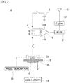
- a current integrator 10 having a space charge measurement apparatus provided together therewith will be hereinafter described with reference to Fig. 7 .
- the same configurations in Fig. 7 as those in Fig. 1 will be designated by the same reference characters, and the description thereof will not be repeated.
- capacitor 4 and amplifier 5 for measuring integration value Q of the current are arranged on the high voltage side of insulator 9 (on the upstream side of electrode 2A connected to DC power supply 3). This arrangement is made for preventing the influence of the pulse voltage of a pulse generator 14 (described later) from being exerted upon the above-described integration value Q.
- an AC/DC converter 11 a short-range wireless communication unit 12 based on ZigBee standard, an antenna 13 are connected to an amplifier 5, so as to allow wireless transmission of the measurement results of integration value Q.
- a space charge measurement apparatus is provided on the downstream side of capacitor 4 and amplifier 5.
- the space charge measurement apparatus has a known configuration (for example, JEC-TR-61004, "Calibration for Space Charge Distribution Measurement using Pulsed Electro-Acoustic Method "); IEC Technical Specification "Calibration of Space Charge Measuring Equipment based on Pulsed Electro-Acoustic Measurement Principle", IEC TS 62758, 18 Sep. 2012 ).
- the space charge measurement apparatus includes a pulse generator 14 configured to apply a pulse voltage to insulator 9, a piezoelectric element 15 configured to sense vibrations caused by movement of electric charge inside insulator 9, and an oscilloscope 16 configured to monitor the measurement result by piezoelectric element 15.
- the space charge measurement apparatus is configured to recognize generation and movement of the space charge in insulator 9, that is, to recognize uneven distribution of space charge in insulator 9. When there is an uneven distribution, it should be regarded that a certain local change of insulation performance occurs in insulator 9. Space charge leads to generation of the space charge accumulation current in insulator 9. Accordingly, it is considered that the change in insulation performance of insulator 9 can be more specifically evaluated by measuring the space charge together with the result of integration value Q of the current.
- current integrator 1 shown in Fig. 1 was used to evaluate the insulation performance of each of three insulating materials during application of a DC voltage.
- the first insulating material is low density polyethylene (LDPE).
- Insulator 9 made of LDPE had a thickness of about 0.2 mm, electrode 2A had a diameter of 73 mm, and electrode 2B had a diameter of 54 mm.
- oil was not applied onto the interface between insulator 9 and each of electrodes 2A and 2B.
- the eight applying conditions were set in which final attained voltages were different, as follows.
- the conditions other than the final attained voltage were the same and set as follows: voltage rising rate; 133 V/sec, applying time period; 600 seconds after reaching the final attained voltage, and the holding time period after stopping voltage application; 300 seconds.
- Fig. 8 shows a graph obtained by plotting integration value Q of the current on each of the applying conditions.
- the horizontal axis shows time t (sec) and the vertical axis shows integration value Q of the current (coulomb).
- the value of the current flowing through insulator 9 is extremely weak, so that it is difficult to directly measure a current value I.
- integration value Q of the current by differentiating integration value Q of the current with respect to the time, that is, by obtaining the inclination of the graph of integration value Q of the current at a specific time, current value I of the current flowing through insulator 9 at the specific time can be obtained.
- integration value Q of the current was differentiated to obtain the relation between time t and current value I. The result thereof is shown in the graph in Fig. 9 .
- the horizontal axis shows time t (sec) and the vertical axis shows current value I (ampere).
- Q 300 /Q 0 serves as an indicator for estimating the degree of accumulation of space charge in insulator 9.
- Fig. 10 shows a graph in which the horizontal axis shows an electric field E (kV/mm) and the vertical axis shows the value of Q 300 /Q 0 .
- electric field E is obtained by dividing the applied voltage by the thickness of insulator 9.
- the thickness of insulator 9 is about 0.2 mm, so that the electric field becomes 100 kV/mm.
- the second insulating material is high density polyethylene (HDPE).
- HDPE high density polyethylene
- integration value Q of the current, current value I and Q 300 /Q 0 were calculated in the same manner as in the case of insulator 9 made of LDPE.
- Fig. 11 shows the result of integration value Q of the current
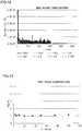
- Fig. 12 shows the result of current I
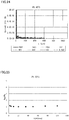
- Fig. 13 shows the result of Q3 00 /Q 0 .
- the third insulating material is polystyrene (PS).
- PS polystyrene
- integration value Q of the current, current value I and Q 300 /Q 0 were calculated in the same manner as in the case of insulator 9 made of LDPE.
- Fig. 14 shows the result of integration value Q of the current
- Fig. 15 shows the result of current value I
- Fig. 16 shows the result of Q3 00 /Q 0 .
- integration values Q of three insulating materials in the fourth embodiment were measured at a measurement temperature different from that in the fourth embodiment, to obtain the measurement results, which were then compared with the measurement results in the fourth embodiment.
- Integration value Q of the current, current value I, and Q 300 /Q 0 were obtained in the same manner as in the fourth embodiment except for the measurement temperature set at 80 °C.
- Figs. 17 , 18, and 19 show integration value Q, current value I and Q 300 /Q 0 , respectively, about LDPE.
- Figs. 20, 21 , and 22 show integration value Q, current value I and Q 300 /Q 0 , respectively, about HDPE.
- Figs. 23 , 24, and 25 show integration value Q, current value I and Q 300 /Q 0 , respectively, about PS.
- the evaluation method for insulation performance of an insulator according to the embodiment can be suitably utilized for evaluating the temporal change in insulation performance of an insulator.
- the evaluation method for insulation performance of an insulator according to the embodiment can be utilized for: deterioration diagnosis of an insulating layer of a power cable for DC power transmission, for example, a superconductive cable; deterioration diagnosis of an insulating layer (an insulator) of an oil-impregnated insulation cable; and deterioration diagnosis of a solid insulator of a solid insulation cable.
- the evaluation method can be utilized also for deterioration diagnosis of an insulator included in an electrical device other than a power cable, for example, such as a capacitor, a battery and the like that are used with a DC voltage applied thereto. Furthermore, even in the case of an electrical device used at an alternating current, but as long as the state change of the insulator provided in the electrical device, for example, water tree deterioration, deterioration of the insulator caused by high temperature or exposure to radiation, and the like are captured by the monitoring method of the present invention, it is considered that there may be a way to utilize the monitoring method of the present invention as a method of tracking the state change in the insulator at an alternating current.
Landscapes
- Physics & Mathematics (AREA)
- General Physics & Mathematics (AREA)
- Engineering & Computer Science (AREA)
- General Engineering & Computer Science (AREA)
- Testing Relating To Insulation (AREA)
- Testing Of Short-Circuits, Discontinuities, Leakage, Or Incorrect Line Connections (AREA)
Abstract
Description
- The present invention relates to an evaluation method for insulation performance of an insulator.
- The present application claims priority based on Japanese Patent Application No.
2016-041451 filed on March 3, 2016 - Conventionally, a method of deterioration diagnosis for an insulating layer in a power cable for alternating-current (AC) power transmission has been variously studied. For example, in
PTD 1, a deterioration diagnosis for an insulating layer is carried out concurrently using the residual charge method and the loss current method, both of which are applied in a cable in service using an AC voltage. - On the other hand, a technique for estimating a change in insulation performance of an insulator is disclosed, for example, in
NPD 1. InNPD 1, when a direct-current (DC) voltage is applied to an insulator, the amount of electric charge accumulated inside the insulator is estimated to evaluate the insulation performance of the insulator. - PTD 1: Japanese Patent Laying-Open No.
2013-029450 - NPD 1: "Deduction of Electric Charge Distribution in Polymer Film" by Tatsuo TAKADA, Takao SAKAI, Yotsuo TORIYAMA, (The transactions of the Institute of Electrical Engineers of Japan, Vol. 92-A, No. 12, pages 537 to 544, 1972)
- An evaluation method for insulation performance of an insulator according to one embodiment of the present invention includes: a step α of applying a DC voltage to a first insulator on a prescribed applying condition, and measuring an integration value of a current flowing through the first insulator from a start of application of the DC voltage until an elapse of a prescribed time period after an end of application of the DC voltage; a step β of applying a DC voltage to a second insulator on an applying condition that is identical to the applying condition in the step α, and measuring an integration value of a current flowing through the second insulator from a start of application of the DC voltage until an elapse of a prescribed time period after an end of application of the DC voltage; and a step γ of comparing (i) a first graph showing a relation between an elapsed time period and the integration value that are obtained in the step α and (ii) a second graph showing a relation between an elapsed time period and the integration value that are obtained in the step β, to evaluate a difference between insulation performance of the first insulator and insulation performance of the second insulator, the difference being caused by applying the DC voltage. Each of integration values is obtained by a current integrator including: a capacitor connected in series to a corresponding one of the first insulator and the second insulator; and a voltmeter configured to measure a voltage applied to the capacitor, the current integrator being configured to measure each of the integration values based on a measurement result of the voltmeter. The applying condition includes: a voltage raising operation for raising a voltage from 0 kV to a prescribed final attained voltage; a voltage holding operation for holding the final attained voltage for a fixed time period; a discharge operation for discharging the capacitor while stopping application of a voltage; and a grounding operation for grounding the capacitor.
-
-
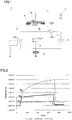
Fig. 1 is a schematic circuit diagram of a current integrator configured to apply a DC voltage to an insulating sample to measure an integration value of the current flowing through the sample over time. -
Fig. 2 is a graph showing the current integration measured in the state where the insulating sample is placed in oil. -
Fig. 3 is a graph showing the current value measured in the state where the insulating sample is placed in oil. -
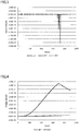
Fig. 4 is a graph showing the integration value of the current measured in the state where the insulating sample left for two months is placed in oil. -
Fig. 5 is a graph of the integration value of the current measured in the state where the insulating sample is placed in the air. -
Fig. 6 is a partially enlarged view of the graph inFig. 5 . -
Fig. 7 is a schematic circuit diagram of a current integrator provided together with a space charge measurement apparatus. -
Fig. 8 is a graph of the integration value of the current in low density polyethylene at a room temperature. -
Fig. 9 is a graph of the current value in low density polyethylene at a room temperature. -
Fig. 10 is a graph of Q300/Q0 of low density polyethylene at a room temperature. -
Fig. 11 is a graph of the integration value of the current in high density polyethylene at a room temperature. -
Fig. 12 is a graph of the current value in high density polyethylene at a room temperature. -
Fig. 13 is a graph of Q300/Q0 in high density polyethylene at a room temperature. -
Fig. 14 is a graph of the integration value of the current in polystyrene at a room temperature. -
Fig. 15 is a graph of the current value in polystyrene at a room temperature. -
Fig. 16 is a graph of Q300/Q0 in polystyrene at a room temperature. -
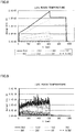
Fig. 17 is a graph of the integration value of the current in low density polyethylene at 80 °C. -
Fig. 18 is a graph of the current value in low density polyethylene at 80 °C. -
Fig. 19 is a graph of Q300/Q0 in low density polyethylene at 80 °C. -
Fig. 20 is a graph of the integration value of the current in high density polyethylene at 80 °C. -
Fig. 21 is a graph of the current value in high density polyethylene at 80 °C. -
Fig. 22 is a graph of Q300/Q0 in high density polyethylene at 80 °C. -
Fig. 23 is a graph of the integration value of the current in polystyrene at 80 °C. -
Fig. 24 is a graph of the current value in polystyrene at 80 °C. -
Fig. 25 is a graph of Q300/Q0 in polystyrene at 80 °C. - In recent years, high-voltage DC power transmission has been studied, and it is considered that a method for diagnosing the state of an insulating layer (a layer formed of an insulator) included in a power cable is required. Furthermore, in consideration of the present circumstances in which it has been examined that not only a power cable but also various electrical devices are used at a direct current, it is considered that a method for diagnosing the state of an insulator at a DC voltage is required. However, there is currently no effective method for diagnosing the state of an insulator associated with application of a DC voltage.
- On the inside of the insulator of the power cable or the electrical device used at a direct current, space charge is more likely to be accumulated at a DC voltage as compared with an AC voltage, so that distortion occurs in the internal electric field of an insulator. It is considered that, in the insulator to which a DC voltage is applied, insulation deterioration is facilitated by combined factors such as accumulation of space charge and oxidation by temperature rise. However, there is no law-like regularity in the manner of accumulation of such space charge, and thus, the detailed mechanism of deterioration of an insulator has not been clarified. For example, as a power cable used for DC power transmission, there are an oil-impregnated insulation cable including an insulating layer (an insulator) obtained by winding oil-impregnated paper around a conductor, and a solid insulation cable obtained by covering a conductor with a solid insulator such as cross-linked polyethylene, which are different in the manner of accumulation of space charge depending on insulators, and also different in the manner of deterioration of each insulator. In view of the above-described circumstances, as a technique leading to the state diagnosis for an insulator in a power cable for DC power transmission and an electrical device used at a direct current, it has been required to develop a method for monitoring changes in insulation performance of an insulator over time that are caused by application of a DC voltage so as to evaluate a difference in insulation performance of the insulator that is caused by application of a DC voltage.
- An object of the present disclosure is to provide an evaluation method for insulation performance of an insulator, by which a difference in insulation performance of an insulator that is caused by application of a DC voltage can be evaluated.
- Generally, when a DC voltage is applied to an insulator sandwiched between electrodes, a weak current flows through the insulator. The current mainly includes a charge current, a space charge accumulation current, a leakage current, and a partial discharge current.
- A charge current (which may also be referred to as a displacement current): the insulator sandwiched between electrodes has exactly the same configuration as a capacitor. Accordingly, by starting application of a DC voltage, charge accumulation accompanied with a change in dipole alignment occurs. The current that flows in that situation is a charge current, which changes in accordance with the relative dielectric constant of the insulator. This charge current is a current that flows only for a prescribed time period from the start of application of a DC voltage.
- A space charge accumulation current (which may also be referred to as an absorption current): a current generated in an insulator in accordance with generation and movement of space charge when a DC voltage is applied to the insulator. This space charge accumulation current flows only for a prescribed time period from the start of application of a DC voltage, like a charge current.
- A leakage current: an extremely weak current flows even through an insulator. Namely, the current that flows in accordance with the electric conductivity of the insulator is a leakage current. The leakage current flows for a time period during which a DC voltage is applied.
- A partial discharge current: when there is a discharge gap inside the insulator, partial discharge (corona) occurs in the discharge gap. The current that instantaneously flows at that time is a partial discharge current.
- Each current that flows through the insulator as described in the above paragraph is extremely weak. Accordingly, only by measuring an instantaneous current value, it cannot be possible to sufficiently recognize temporal changes in physical quantities of the insulator that are related to the insulation performance of the insulator (four types including: a relative dielectric constant, space charge accumulation, electric conductivity, and existence of a discharge gap). Thus, the present inventors have attempted to clarify the behavior of each current that flows through the insulator by applying a DC voltage to an insulator to exhaustively measure the integration value of the current flowing through the insulator from the start of application of a DC voltage until an elapse of a prescribed time period after the end of application of a DC voltage. The integration value of the current can be calculated as follows. Specifically, a sufficiently large capacitor with respect to the capacitance of the insulator is connected in series to the insulator, and then, the voltage to be applied to the capacitor is measured, so that the integration value of the current can be calculated. By comparing the behaviors of the current over time based on such measurement of the integration value, the present inventors have conceived of a method of evaluating the difference in insulation performance of the insulator. In the following, an evaluation method for insulation performance of an insulator according to an embodiment will be specified.
- Details of the embodiment of the invention of the present application will be first described.
- <1> An evaluation method for insulation performance of an insulator according to an embodiment includes: a step α of applying a DC voltage to a first insulator on a prescribed applying condition, and measuring an integration value of a current that flows through the first insulator from a start of application of the DC voltage until an elapse of a prescribed time period after an end of application of the DC voltage; a step β of applying a DC voltage to a second insulator on an applying condition that is identical to the applying condition in the step α, and measuring an integration value of a current that flows through the second insulator from a start of application of the DC voltage until an elapse of a prescribed time period after an end of application of the DC voltage; and a step γ of comparing (i) a first graph showing a relation between an elapsed time period and the integration value that are obtained in the step α and (ii) a second graph showing a relation between an elapsed time period and the integration value that are obtained in the step β, to evaluate a difference between insulation performance of the first insulator and insulation performance of the second insulator, the difference being caused by applying the DC voltage. Each of integration values is obtained by a current integrator including: a capacitor connected in series to a corresponding one of the first insulator and the second insulator; and a voltmeter configured to measure a voltage applied to the capacitor, the current integrator being configured to measure each of the integration values based on a measurement result of the voltmeter. The applying condition includes: a voltage raising operation for raising a voltage from 0 kV to a prescribed final attained voltage; a voltage holding operation for holding the final attained voltage for a fixed time period; a discharge operation for discharging the capacitor while stopping application of a voltage; and a grounding operation for grounding the capacitor.
In the evaluation method for insulation performance of an insulator makes utilization of the feature that the time integration value of the current corresponds to electric charge. When an integration capacitor is connected in series to an insulator, to which a DC voltage is applied, the same amount of electric charge as that accumulated in the insulator is accumulated also in the integration capacitor. The time integration value of the current is measured by this method. Accordingly, by setting the measuring time period to be relatively long, even a micro current can be sufficiently sensed.
In the evaluation method for insulation performance of an insulator, the voltage applied to an integration capacitor is measured during a time period from a start of voltage application until grounding. Specifically, the integration value of every current flowing through an insulator during a time period from a start of voltage application through a discharge operation until grounding is exhaustively measured. The voltage application procedure including the above-described operations imitates the actual manner of using a DC device. Accordingly, based on the information obtained in the above voltage application procedure, the insulation performance of the insulator can be evaluated in accordance with the actual manner of use.
During the voltage raising operation in the voltage application procedure, the voltage is still low, and the influence of the charge current upon the integration value is predominant. Also, in the early stage of the voltage holding operation, the influence of the space charge accumulation current upon the integration value is high. In the latter stage of the voltage holding operation, the influence of the leakage current upon the integration value is high. Based on the information obtained in each of the operations, by checking the integration value of the current that flows through the insulator in accordance with application of a DC voltage, the details of the change in each current that flows through the insulator can be obtained. Then, based on the change in current, the change in insulation performance of the insulator can be obtained. Thus, by comparing the data of the first insulator obtained in step α and the data of the second insulator obtained in step β, the difference in insulation performance between the first and second insulators can be evaluated. - <2> As one aspect of the evaluation method for insulation performance of an insulator according to an embodiment, there may be an embodiment in which the second insulator is provided as the first insulator that is changed in insulation performance, and the step α and the step β are identical in measurement environment condition.
The first insulator that is changed in insulation performance means the first insulator that is obtained after the first insulator measured in step α is left in an environment, applied with thermal hysteresis, or applied with a prescribed voltage. In other words, the first insulator is the second insulator before undergoing a state change. Namely, in step β of the above-described configuration, after an elapse of a prescribed time period since step α is performed, the first insulator used in step α is again measured in the same measurement environment as that in step α. In step γ, by comparing the result obtained in step α and the result obtained in step β, the temporal change in insulation performance of the insulator can be evaluated. Also, by comparing the result obtained in step α and the result obtained in step β, the mechanism of the change in insulation performance of the insulator may be able to be clarified. - <3> As one aspect of the evaluation method for insulation performance of an insulator according to an embodiment, there may be an embodiment in which the second insulator is made of a material different from a material of the first insulator, and the step α and the step β are identical in measurement environment condition.
According to the above-described evaluation method, the optimal material of the insulator in accordance with a use purpose can be specified. For example, in the use situation in which not only insulation performance but also mechanical strength is required, when there are two materials that are approximately identical in mechanical strength, it becomes possible to check, by using the above-described evaluation method, as to which material is suitable as an insulator at a prescribed DC voltage. - <4> As one aspect of the evaluation method for insulation performance of an insulator according to an embodiment, there may be an embodiment in which the second insulator is made of a material identical to a material of the first insulator, and the step α and the step β are different in measurement environment condition.
Examples of the measurement environment may include a temperature, humidity, an atmosphere, pressure, and the like. For example, when the measurement is conducted at a room temperature in step α and the measurement is conducted at 100 °C in step β, it can be examined whether the insulator is preferable or not to be used in an environment where the temperature changes from a room temperature to 100 °C. - <5> As one aspect of the evaluation method for insulation performance of an insulator according to an embodiment, there may be an embodiment including: a step δ of applying a DC voltage to the first insulator on an applying condition that is different only in the final attained voltage from the applying condition in the step α, and measuring an integration value of a current that flows through the first insulator from a start of application of the DC voltage until an elapse of a prescribed time period after an end of application of the DC voltage; and a step ε of applying a DC voltage to the second insulator on an applying condition that is identical to the applying condition in the step δ, and measuring an integration value of a current that flows through the second insulator from a start of application of the DC voltage until an elapse of a prescribed time period after an end of application of the DC voltage. The step γ includes evaluating a difference between the insulation performance of the first insulator and the insulation performance of the second insulator, together with a measurement result obtained in the step δ and a measurement result obtained in the step ε.
According to the above-described measuring method, it becomes possible not only to compare the result obtained in step α and the result obtained in step β at the same voltage, but also to obtain the information about the insulation performance of the first insulator and the information about the insulation performance of the second insulator at different voltages. As a result, the insulation performance of each insulator at a DC voltage can be more specifically evaluated. - <6> As one aspect of the evaluation method for insulation performance of an insulator according to an embodiment, there may be an embodiment in which each insulation performance is a relative dielectric constant of a corresponding one of the first insulator and the second insulator. The relative dielectric constant corresponds to a portion that exists in the first graph or the second graph and that is related to a charge current accumulated in each of the first insulator and the second insulator. The relative dielectric constant is calculated from each of the integration values obtained in a portion from a start of application of the DC voltage until a prescribed time period.
As described above, the charge current is a current that flows in the case where an insulator and an electrode for applying a DC voltage to the insulator are regarded as a capacitor. Also, the charge current is a current related to the relative dielectric constant of the insulator. The charge current flows for a short time period from a start of application of a DC voltage. Accordingly, by checking the integration value of the current in the early stage at the start of application of a DC voltage in the graph, the magnitude of the charge current, that is, the relative dielectric constant of the insulator, can be recognized and evaluated. For example, when the second insulator is the first insulator that is changed in insulation performance, the temporal change in relative dielectric constant of the insulator can be recognized by comparing the integration value in step α and the integration value in step β. - <7> As one aspect of the evaluation method for insulation performance of an insulator according to an embodiment, there may be an embodiment in which each insulation performance is electric conductivity of a corresponding one of the first insulator and the second insulator. The electric conductivity corresponds to a portion that exists in the first graph or the second graph and that is related to a leakage current flowing through each of the first insulator and the second insulator. Also, the electric conductivity is calculated from an inclination of each of the integration values obtained after an elapse of a prescribed time period since a start of application of the DC voltage.
As described above, the leakage current is a current related to the electric conductivity of the insulator and flows during application of a DC voltage to the insulator. Thus, in order to obtain the magnitude of the leakage current, it is preferable to check the inclination of the integration value of the current after an elapse of a prescribed time period since a start of application of a DC voltage, that is, in a time zone considered that there is almost no influence of a charge current or a space charge accumulation current that flows for a short time period after a start of application of a DC voltage. By checking the inclination of the integration value of the current in the time zone in which there is almost no influence of a charge current or a space charge accumulation current, the magnitude of the leakage current, that is, the electric conductivity of the insulator, can be recognized and evaluated. For example, when the second insulator is the first insulator that is changed in insulation performance, by comparing the inclination of the integration value of the current in the time zone in step α and the inclination of the integration value of the current in the time zone in step β, the temporal change in electric conductivity of the insulator can be recognized. In this case, the reciprocal of the electric conductivity of the insulator is the volume resistivity of the insulator. When the electric conductivity is obtained, the volume resistivity can also be obtained by calculation. - <8> As one aspect of the evaluation method for insulation performance of an insulator according to an embodiment, there may be an embodiment in which each insulation performance is a state of existence of a discharge gap inside a corresponding one of the first insulator and the second insulator, and the state of existence of the discharge gap is obtained by specifying a portion that exists in the first graph or the second graph and that is related to a partial discharge current flowing through each of the first insulator and the second insulator.
As described above, the partial discharge current is a current that is generated when partial discharge occurs in the discharge gap inside the insulator, and that flows randomly during application of a DC voltage to the insulator. Thus, in order to find occurrence of a partial discharge current, it is preferable to check a sudden increase in integration value of the current (a step-wise increase in integration value). By checking the magnitude and the frequency of the partial discharge current, the state of existence (the amount and the magnitude) of the discharge gap inside the insulator can be recognized and evaluated. For example, when the second insulator is the first insulator that is changed in insulation performance, by comparing the occurrence frequency and the magnitude of the partial discharge current in step α with the occurrence frequency and the magnitude of the partial discharge current in step β, the state of formation of the discharge gap in the insulator over time can be recognized. - <9> As one aspect of the evaluation method for insulation performance of an insulator according to an embodiment for specifying a portion existing in the graph and related to a partial discharge current, there may be an embodiment in which each of the step α and the step β includes sensing a timing of occurrence of partial discharge by a sensor configured to sense a high frequency pulse generated during partial discharge, to specify the partial discharge current in each of the first graph and the second graph.
During partial discharge, a high frequency current flows through the insulator. By sensing the pulse of the high frequency current by the sensor to recognize the timing of occurrence of partial discharge, it becomes possible to reliably specify the position at which partial discharge occurs in the graph of the integration value of the current. As a result, the existence of the discharge gap formed inside the insulator can be more accurately estimated. - <10> As one aspect of the evaluation method for insulation performance of an insulator according to an embodiment, there may be an embodiment in which each insulation performance is an accumulation behavior of space charge in a corresponding one of the first insulator and the second insulator, and an influence of the accumulation behavior of the space charge is calculated by comparing QA/Q0 in the first graph or the second graph. In this case, Q0 is the integration value at time T0 at which a charge current accumulated in each of the first insulator and the second insulator after an elapse of a prescribed time period since a start of application of the DC voltage decreases to a negligible level, and QA is the integration value at time TA after an elapse of a prescribed time period since the time T0.
In the graph showing the integration value of the current, in the course of process from the time zone in which the charge current flowing for a short time period after a start of application of a DC voltage has a significant influence to the time zone in which the leakage current flowing in the equilibrium state has a significant influence, space charge accumulates inside the insulator while moving around the insulator for several minutes to several dozen minutes. In this space charge accumulation, there is a repetition of processes of generation, movement, or capturing and accumulation of electric charge. The time period of this repetition is so long as several minutes or more. Since space charge has potential energy of a chemical reaction, it facilitates complex insulation deterioration resulting from the existence of oxygen and moisture together with the influence of temperature. Accordingly, it is an important factor to conduct a measurement in accordance with application of a DC voltage for evaluating deterioration in insulation performance of the insulator.
As described above, since space charge accumulation is an important factor for evaluating the deterioration in insulation performance of the insulator, it is also extremely important to recognize its behavior. However, in the time zone in which a space charge accumulation current flows, the charge current has already decreased to a negligible level but is in coexistence with the leakage current. Thus, it becomes important to separate the space charge accumulation current and the leakage current from each other. The method for such separation can be conceivable as follows. Specifically, an integration value Q0 at the time when the section of the charge current in the early stage of voltage application is ended and switched to the section in which a space charge accumulation current and a leakage current may exist (time T0) is calculated; and an integration value QA at time TA after an elapse of a prescribed time period since time T0 is calculated. Then, by checking a ratio QA/Q0, the influence of space charge can be recognized. For example, when the influence of the space charge accumulation current is small and almost no leakage current flows, QA/Q0 is approximately equal to 1. On the other hand, when the influence of the space charge accumulation current becomes large, QA/Q0 shows a value of 1.1 to 1.5. Furthermore, when a leakage current is a main component, QA/Q0 becomes a value exceeding 1.5. By graphically plotting QA/Q0 with respect to the applied voltage, the voltage influenced by space charge and the voltage composed mainly of a leakage current can be recognized and evaluated. - <11> As one aspect of the evaluation method for insulation performance of an insulator according to an embodiment for obtaining a space charge accumulation current, there may be an embodiment in which each of the step α and the step β includes sensing the accumulation behavior of the space charge by a pulsed electro-acoustic (PEA) method, to specify the accumulation behavior of the space charge in each of the first graph and the second graph.
The PEA method is a measuring method by which the amount and the location information of the space charge in the insulator applied with a DC voltage can be obtained. Accordingly, it is considered that the change in insulation performance of the insulator, for example, local deterioration in insulation performance and the like can be specifically recognized by complexly analyzing the information about the space charge accumulation current obtained from the graph of the integration value of the current and the information obtained by the PEA method. - <12> As one aspect of the evaluation method for insulation performance of an insulator according to an embodiment, there may be an embodiment in which the current integrator is disposed on a ground side of each of the first insulator and the second insulator to measure a corresponding one of the integration values.
The above-described configuration is suitable when a device for sensing a high frequency pulse generated when a partial discharge current flows is provided together with a current integrator. - <13> As one aspect of the evaluation method for insulation performance of an insulator according to an embodiment, there may be an embodiment in which the current integrator is disposed on a high voltage side of each of the first insulator and the second insulator to measure a corresponding one of the integration values.
- The above-described configuration is suitable when a device for measuring space charge in an insulator is provided together with a current integrator.
- In the following, embodiments of an evaluation method for insulation performance of an insulator according to an embodiment will be described. It is to be noted that the invention of the present application is not limited to the configuration shown in each embodiment, but defined by the terms of the claims, and is intended to include any modifications within the meaning and scope equivalent to the terms of the claims.
- In the first embodiment, a
current integrator 1 shown inFig. 1 is used to measure the integration value of the current flowing through aninsulator 9 in accordance with application of a DC voltage, to evaluate the change in insulation performance ofinsulator 9.Insulator 9 used for measurement is obtained by stacking two sheets of kraft paper that is impregnated with polybutene and that has a thickness of 0.1 mm. - The configuration of
current integrator 1 inFig. 1 will be hereinafter simply described.Current integrator 1 includeselectrodes 2B sandwiching insulator 9, aDC power supply 3, acapacitor 4, anamplifier 5, avoltmeter 6, arelay 7, and a high frequencycurrent transformer 8. -
Electrode 2A attached to one surface side ofinsulator 9 is an electrode on the high electric potential side, which is connected toDC power supply 3 through a resistance and a switch. On the other hand,electrode 2B is an electrode on the low electric potential side, which is attached to the surface ofinsulator 9 on the opposite side ofelectrode 2A.Electrodes electrodes insulator 9, that is, 0.2 mm. - In
capacitor 4, the electric charge that flows throughinsulator 9 is accumulated. The accumulated electric charge is amplified byamplifier 5 and measured over time byvoltmeter 6, so that the integration value of the current having flown throughinsulator 9 can be obtained. The integration value of the current can be obtained by measuring the voltage ofcapacitor 4 because the relation Q = CV is satisfied. In this case, C (capacitance of the capacitor) is already known (10 µF in the present example). Thus, when a voltage (V) ofvoltmeter 6 is obtained, the amount of electric charge (the integration value of the current) can be calculated. - In addition,
relay 7 serves to allow the electric charge accumulated incapacitor 4 to leak to a ground for clearing the measurement result. Furthermore, high frequencycurrent transformer 8 functions as a sensor for sensing the high frequency pulse generated when partial discharge occurs ininsulator 9. High frequencycurrent transformer 8 is connected to an oscilloscope (not shown), and can sense the timing of occurrence of a high frequency pulse current. - The above-described
current integrator 1 is used to apply a DC voltage on a prescribed applying condition. The prescribed applying condition includes: a condition about the voltage rising rate (v/sec) at which a DC voltage is applied; a condition about the level at which the final DC voltage (applied voltage) is set; a condition about the time period during which the voltage is applied; and a condition about the time period elapsing from after stopping voltage application until grounding. In the present example, a DC voltage was applied on the following three applying conditions. Even after the switch ofcurrent integrator 1 was turned off to end application of the DC voltage, integration value Q was measured until grounding. - (1) Voltage rising rate; 133 V/sec, final attained voltage; 2 kV, applying time period; 600 seconds after reaching 2 kV, holding time period after stopping voltage application; 180 seconds.
- (2) Voltage rising rate; 133 V/sec, final attained voltage; 5 kV, applying time period; 600 seconds after reaching 5 kV, holding time period after stopping voltage application; 180 seconds.
- (3) Voltage rising rate; 133 V/sec, final attained voltage; 8 kV, applying time period; 600 seconds after reaching 8 kV, and holding time period after stopping voltage application; 180 seconds.
-
Fig. 2 shows a graph obtained by graphically plotting integration value Q of the current at the time when a DC voltage is applied on the above-described three applying conditions. In the graph, the horizontal axis shows time t (sec) and the vertical axis shows an integration value Q of a current (coulomb). InFig. 2 , the measurement results of integration value Q of the current on the applying conditions in the above-described (1), (2), and (3) are shown by a thin solid line, a bold solid line and a dotted line, respectively. The graph shows the result obtained by starting voltage application after 60 seconds after the start of measurement of the current integration, raising the voltage to a final attained voltage at a prescribed voltage rising rate, and then, holding the final attained voltage for 600 seconds, and stopping voltage application and further holding the voltage for 180 seconds, and finally, short-circuiting andgrounding relay 7 inFig. 1 . The voltage rising rate, the final attained voltage, the voltage holding time period, and the holding time period after stopping voltage application can be selected as appropriate in accordance with the details of the examination to be executed. Furthermore, it is considered that the behavior of the change in integration value during a time period from when voltage application is stopped until when the insulator and the current integrator are grounded is also important for analyzing the change in insulation performance of the insulator. Thus, the integration values are measured exhaustively from voltage rising to grounding. In this case, the integration value of the current was measured in the state whereinsulator 9 was immersed in insulating oil. In this way, occurrence of partial discharge can be suppressed, so that the measurement results can be less influenced by the partial discharge current. - As shown in
Fig. 2 , when voltage application is started 60 seconds after the start of measurement, integration value Q suddenly starts to increase. Such a sudden increase in integration value Q corresponds to a charge current that flows wheninsulator 9 andelectrodes electrodes electrodes insulator 9 increases,insulator 9 is more likely to undergo dielectric polarization by application of a DC voltage. Thus, it can be considered that the insulation performance ofinsulator 9 deteriorates. - Further referring to
Fig. 2 , after a sudden increase of integration value Q, integration value Q increases in a gradual and slow manner. This is because almost no charge current flows at this time, thereby leading to the state where a space charge accumulation current and a leakage current exclusively flow throughinsulator 9. In this case, a nonlinear inflection point is formed in the graph. Accordingly, it can be readily recognized by observation of the graph that the state where a charge current flows throughinsulator 9 has been changed to the state where a space charge accumulation current and a leakage current flow throughinsulator 9. - Specifically, in the time zone in which the influence of the space charge accumulation current is negligible (the time zone surrounded by an alternate long and short dash line in
Fig. 2 ), which is included in the time zone in which the space charge accumulation current and the leakage current flow (the time zone after the inflection point shown by an outlined arrow inFig. 2 ), the electric conductivity ofinsulator 9 can be obtained from the inclination of integration value Q of the current. The electric conductivity ofinsulator 9 can be obtained by (1/S) × (dQ/dt) × (a/Vdc). In this case, S, a, and Vdc in this expression are as already described above, and dQ/dt shows the inclination of integration value Q. An increase in electric conductivity can be regarded as a decrease in insulation performance ofinsulator 9. - The influence of accumulation of space charge is calculated from the integration value of the current in the time zone in which a space charge accumulation current is dominant, which is included in the time zone in which a leakage current and a space charge accumulation current flow. Specifically, integration value Q0 at the time when the charge current decreases to a negligible level (time T0) (the integration value of the current at the inflection point shown by an outlined arrow in each graph in
Fig. 2 ) is calculated, and integration value QA at time TA after an elapse of a prescribed time period from the measurement point of Q0 is calculated. Then, based on the value of the ratio QA/Q0, the degree of accumulation of space charge can be estimated. For example, when no leakage current flows and when there is no space charge accumulation, QA/Q0 becomes approximately 1. When the influence of the space charge accumulation current is high, QA/Q0 is increased to approximately 1.1 to 1.5. Furthermore, when the applied voltage is high and the leakage current is dominant, QA/Q0 suddenly increases over 1.5. However, such an evaluation needs to be performed within the range of ΔQ < QA. - Then, integration value Q0 in
Fig. 2 and an integration value Q300 after an elapse of 300 seconds from the measurement point of integration value Q0 are extracted to calculate the ratio Q300/Q0. The result thereof is shown in Table 1, in which Q300/Q0 is 1.20 at the applied voltage of 2 kV, and Q300/Q0 is 1.57 at the applied voltage of 8 kV. It is considered that this shows that the space charge accumulation current is dominant during application of a low voltage of 2 kV, but the leakage current is dominant during application of a high voltage of 8 kV. In this way, by comparing QA/Q0 calculated on one day ("A" day) with QA/Q0 calculated on another day ("B" day), the change in space charge accumulation can be obtained.[Table 1] Applied Voltage Actual Measured Value of Q (coulomb) Ratio Q300/Q0 Q0 Q300 2 kV 7.5 × 10⁻⁸ 9.0 × 10⁻⁸ 1.20 8 kV 3.4 × 10⁻⁷ 5.3 × 10⁻⁷ 1.57 -
Fig. 3 shows the measurement results of the current value at the time when a DC voltage is applied on the above-described applying conditions (1) to (3). InFig. 3 , the horizontal axis shows a time period (sec) from the start of application of a DC voltage and the vertical axis shows a current value. As shown inFig. 3 , since the current value was extremely weak, it was difficult to recognize a change in value of the current flowing throughinsulator 9, with the result that the insulation performance ofinsulator 9 could not be evaluated. It is to be noted that a large negative current value was measured before and after 700 seconds inFig. 3 because, due to the end of application of the DC voltage, the electric charge equivalent to the capacitance as a capacitor accumulated ininsulator 9 was emitted at once as a discharge current. - As having been described with reference to
Fig. 2 , the change in insulation performance ofinsulator 9 can be evaluated by analyzing each portion of integration value Q of the current in the graph. Specifically, by comparing the first graph of integration value Q of the current measured on one day ("A" day) and the second graph of integration value Q of the current measured on another day ("B" day), the temporal change in relative dielectric constant εr and the temporal change in electric conductivity that are observed ininsulator 9 can be recognized. For reference purposes,Fig. 4 shows the measurement results ofinsulator 9 that has been left for two months in atmospheric air and caused to absorb moisture. The applying condition of the DC voltage during the measurement was the same as the applying condition of 2 kV and the applying condition of 5 kV inFig. 2 . - As shown in
Fig. 4 , the second graph of integration value Q of the current is greatly different from the first graph inFig. 2 . Thus, it turned out that the state change ofinsulator 9 was remarkable. In the example inFig. 4 , sinceinsulator 9 was left in the air, the state change ininsulator 9 was significant. However, it is considered that the change in insulation performance ofinsulator 9 can be specifically tracked by improving the method of storinginsulator 9 or by shortening the measuring span. In addition, the first graph and the second graph to be compared may be obtained at different times on the same day (for example, 9:00 a.m. and 6:00 p.m., and the like). Furthermore, the first graph and the second graph may be obtained before and after an influence is exerted by voltage application or heat application. Then, the change in insulation performance of the insulator caused by voltage application or heat application may be checked. - In the second embodiment,
current integrator 1 inFig. 1 was used to measure integration value Q of the current in the state whereinsulator 9 impregnated with insulating oil (polybutene) was disposed in the air. The result is shown inFig. 5 . The applying condition of a DC voltage is the same as that in the first embodiment. - As shown in the graph in
Fig. 5 , integration value Q of the current increased during a time period from the start of application of a DC voltage after an elapse of 60 seconds after the start of measurement until a certain time (particularly, during voltage rising), then, integration value Q remained almost at the same level after the certain time (see the portion surrounded by an alternate long and short dash line). The portion in which integration value Q suddenly increases corresponds to a portion related to a charge current. It is considered that the partial discharge current caused by partial discharge is reflected in this portion in the case of measurement in the air. - In the second embodiment, integration value Q of the current is measured in the state where
insulator 9 is disposed in the air. Accordingly, the partial discharge current is more likely to be reflected in integration value Q.Fig. 6 shows a change in integration value Q from 50 seconds to 150 seconds in the first graph inFig. 5 . As shown by an arrow inFig. 6 , in the time zone in which the influence of the charge current is dominant, there is a sudden increase in integration value Q that is different from the amount of increase in the charge current. This sudden increase of integration value Q is caused by the partial discharge current. In order to specify that such a sudden increase of integration value Q is caused by partial discharge, it is preferable to simultaneously measure partial discharge. In this case, high frequencycurrent transformer 8 shown inFig. 1 was used. By analyzing the frequency and the rate of such a sudden increase of integration value Q, the amount and the magnitude of the discharge gap insideinsulator 9 can be estimated. Furthermore by comparing the first graph on the "A" day and the second graph on the "B" day, the state of generation of the discharge gap ininsulator 9 can be evaluated. - In the third embodiment, a
current integrator 10 having a space charge measurement apparatus provided together therewith will be hereinafter described with reference toFig. 7 . The same configurations inFig. 7 as those inFig. 1 will be designated by the same reference characters, and the description thereof will not be repeated. - In this
current integrator 10,capacitor 4 andamplifier 5 for measuring integration value Q of the current are arranged on the high voltage side of insulator 9 (on the upstream side ofelectrode 2A connected to DC power supply 3). This arrangement is made for preventing the influence of the pulse voltage of a pulse generator 14 (described later) from being exerted upon the above-described integration value Q. Incurrent integrator 10 in the present example, an AC/DC converter 11, a short-rangewireless communication unit 12 based on ZigBee standard, anantenna 13 are connected to anamplifier 5, so as to allow wireless transmission of the measurement results of integration value Q. - In
current integrator 10 in the present example, a space charge measurement apparatus is provided on the downstream side ofcapacitor 4 andamplifier 5. The space charge measurement apparatus has a known configuration (for example, JEC-TR-61004, "Calibration for Space Charge Distribution Measurement using Pulsed Electro-Acoustic Method"); IEC Technical Specification "Calibration of Space Charge Measuring Equipment based on Pulsed Electro-Acoustic Measurement Principle", ). The space charge measurement apparatus includes apulse generator 14 configured to apply a pulse voltage toinsulator 9, apiezoelectric element 15 configured to sense vibrations caused by movement of electric charge insideinsulator 9, and anoscilloscope 16 configured to monitor the measurement result bypiezoelectric element 15. - The space charge measurement apparatus is configured to recognize generation and movement of the space charge in
insulator 9, that is, to recognize uneven distribution of space charge ininsulator 9. When there is an uneven distribution, it should be regarded that a certain local change of insulation performance occurs ininsulator 9. Space charge leads to generation of the space charge accumulation current ininsulator 9. Accordingly, it is considered that the change in insulation performance ofinsulator 9 can be more specifically evaluated by measuring the space charge together with the result of integration value Q of the current. - In the fourth embodiment,
current integrator 1 shown inFig. 1 was used to evaluate the insulation performance of each of three insulating materials during application of a DC voltage. - The first insulating material is low density polyethylene (LDPE).
Insulator 9 made of LDPE had a thickness of about 0.2 mm,electrode 2A had a diameter of 73 mm, andelectrode 2B had a diameter of 54 mm. At a room temperature in the measurement environment, oil was not applied onto the interface betweeninsulator 9 and each ofelectrodes - The eight applying conditions were set in which final attained voltages were different, as follows. The conditions other than the final attained voltage were the same and set as follows: voltage rising rate; 133 V/sec, applying time period; 600 seconds after reaching the final attained voltage, and the holding time period after stopping voltage application; 300 seconds.
Fig. 8 shows a graph obtained by plotting integration value Q of the current on each of the applying conditions. The horizontal axis shows time t (sec) and the vertical axis shows integration value Q of the current (coulomb). - (1) 0.5 kV (extra-thick dashed line)
- (2) 1 kV (bold solid line)
- (3) 2 kV (bold dotted line)
- (4) 4 kV (bold dashed line)
- (5) 7 kV (thin solid line)
- (6) 10 kV (thin dotted line)
- (7) 15 kV (thin dashed line)
- (8) 20 kV (extra-thick solid line)
- In this case, as having already been described in the first embodiment, the value of the current flowing through
insulator 9 is extremely weak, so that it is difficult to directly measure a current value I. However, by differentiating integration value Q of the current with respect to the time, that is, by obtaining the inclination of the graph of integration value Q of the current at a specific time, current value I of the current flowing throughinsulator 9 at the specific time can be obtained. Thus, integration value Q of the current was differentiated to obtain the relation between time t and current value I. The result thereof is shown in the graph inFig. 9 . InFig. 9 , the horizontal axis shows time t (sec) and the vertical axis shows current value I (ampere). - Furthermore, from the result of integration value Q of the current, Q300/Q0 was calculated as in the first embodiment. As having already been described, Q300/Q0 serves as an indicator for estimating the degree of accumulation of space charge in
insulator 9.Fig. 10 shows a graph in which the horizontal axis shows an electric field E (kV/mm) and the vertical axis shows the value of Q300/Q0. In this case, electric field E is obtained by dividing the applied voltage by the thickness ofinsulator 9. Thus, for example, when the applied voltage is 20 kV, the thickness ofinsulator 9 is about 0.2 mm, so that the electric field becomes 100 kV/mm. - The second insulating material is high density polyethylene (HDPE). As to
insulator 9 made of HDPE, integration value Q of the current, current value I and Q300/Q0 were calculated in the same manner as in the case ofinsulator 9 made of LDPE.Fig. 11 shows the result of integration value Q of the current,Fig. 12 shows the result of current I, andFig. 13 shows the result of Q300/Q0. - The third insulating material is polystyrene (PS). As to
insulator 9 made of PS, integration value Q of the current, current value I and Q300/Q0 were calculated in the same manner as in the case ofinsulator 9 made of LDPE.Fig. 14 shows the result of integration value Q of the current,Fig. 15 shows the result of current value I, andFig. 16 shows the result of Q300/Q0. - By comparing
Figs. 8 ,11 , and14 related to integration value Q of the current, there is not a significant difference in the amount of accumulation of electric charge in each material (integration value Q of the current) when the final attained voltage is so low as about 2 kV or less. However, it turned out that, as the applied voltage is higher, the amount of accumulation of electric charge in LDPE is significantly greater than that in HDPE and PS. Particularly, in the time period from approximately 10 seconds after the start of measurement until approximately 600 seconds in which the space charge accumulation current and the leakage current are dominant, the amount of accumulation of electric charge in LDPE increases to 10-5 level, whereas the amount of accumulation of electric charge in each of HDPE and PS remains at 10-6 level. - Furthermore, when comparing
Figs. 10 ,13 , and16 related to Q300/Q0, Q300/Q0 of each of HDPE (Fig. 13 ) and PS (Fig. 16 ) is stabilized at around 1.0, whereas Q300/Q0 of LDPE (Fig. 10 ) increases in accordance with an increase in electric field E. Particularly, as shown inFig. 10 , when electric field E exceeds 35 kV/mm (applied voltage of 7 kV), Q300/Q0 of LDPE exceeds 1.5. Thus, it turned out that the leakage current of LDPE remarkably increases. The increased leakage current means that the electric conductivity of LDPE has increased. In view of the above results, it is presumed that, when the applied voltage is raised (for example, 5 kV or more), HDPE and PS are more preferable as an insulator than LDPE. - Then, by comparing
Figs. 9 ,12 , and15 related to current value I, the variations in the current during accumulation of electric charge can be recognized. As to LDPE, it turns out fromFig. 9 that not only a large current flows through LDPE, but also there is a significant change in current over time. Also, by comparingFigs 12 and15 , there is almost no difference in current value I and also in temporal change of the current between HDPE (Fig. 12 ) and PS (Fig. 15 ). - In the fifth embodiment, integration values Q of three insulating materials in the fourth embodiment were measured at a measurement temperature different from that in the fourth embodiment, to obtain the measurement results, which were then compared with the measurement results in the fourth embodiment.
- Integration value Q of the current, current value I, and Q300/Q0 were obtained in the same manner as in the fourth embodiment except for the measurement temperature set at 80 °C.
-
Figs. 17 ,18, and 19 show integration value Q, current value I and Q300/Q0, respectively, about LDPE. -
Figs. 20, 21 , and22 show integration value Q, current value I and Q300/Q0, respectively, about HDPE. -
Figs. 23 ,24, and 25 show integration value Q, current value I and Q300/Q0, respectively, about PS. - By comparison between
Fig. 8 (Fig. 10 ) andFig. 17 (Fig. 19 ) related to LDPE, comparison betweenFig. 11 (Fig. 13 ) andFig. 20 (Fig. 22 ) related to HDPE, and comparison betweenFig. 14 (Fig. 16 ) andFig. 23 (Fig. 25 ) related to PS, it turned out that PS (Figs. 23 and25 ) exhibits excellent insulation performance also in a high temperature environment of 80 °C. - Furthermore, by comparing
Figs. 18 ,21 and24 related to current value I, it turned out that, in a high temperature environment of 80 °C, current value I and its change are relatively large in the case of LDPE (Fig. 18 ) and HDPE (Fig. 21 ), but relatively small in the case of PS (Fig. 24 ). - The evaluation method for insulation performance of an insulator according to the embodiment can be suitably utilized for evaluating the temporal change in insulation performance of an insulator. In the future, it is expected that the evaluation method for insulation performance of an insulator according to the embodiment can be utilized for: deterioration diagnosis of an insulating layer of a power cable for DC power transmission, for example, a superconductive cable; deterioration diagnosis of an insulating layer (an insulator) of an oil-impregnated insulation cable; and deterioration diagnosis of a solid insulator of a solid insulation cable. Furthermore, it is expected that the evaluation method can be utilized also for deterioration diagnosis of an insulator included in an electrical device other than a power cable, for example, such as a capacitor, a battery and the like that are used with a DC voltage applied thereto. Furthermore, even in the case of an electrical device used at an alternating current, but as long as the state change of the insulator provided in the electrical device, for example, water tree deterioration, deterioration of the insulator caused by high temperature or exposure to radiation, and the like are captured by the monitoring method of the present invention, it is considered that there may be a way to utilize the monitoring method of the present invention as a method of tracking the state change in the insulator at an alternating current.
- 1, 10 current integrator, 2A, 2B electrode, 3 DC power supply, 4 capacitor, 5 amplifier, 6 voltmeter, 7 relay, 8 high frequency current transformer, 9 insulator, 11 AC/DC converter, 12 short-range wireless communication unit, 13 antenna, 14 pulse generator, 15 piezoelectric element, 16 oscilloscope.
Claims (13)
- An evaluation method for insulation performance of an insulator, the evaluation method comprising:a step α of applying a DC voltage to a first insulator on a prescribed applying condition, and measuring an integration value of a current flowing through the first insulator from a start of application of the DC voltage until an elapse of a prescribed time period after an end of application of the DC voltage;a step β of applying a DC voltage to a second insulator on an applying condition that is identical to the applying condition in the step α, and measuring an integration value of a current flowing through the second insulator from a start of application of the DC voltage until an elapse of a prescribed time period after an end of application of the DC voltage; anda step γ of comparing (i) a first graph showing a relation between an elapsed time period and the integration value that are obtained in the step α and (ii) a second graph showing a relation between an elapsed time period and the integration value that are obtained in the step β, to evaluate a difference between insulation performance of the first insulator and insulation performance of the second insulator due to application of the DC voltage,each of integration values being obtained by a current integrator includinga capacitor connected in series to a corresponding one of the first insulator and the second insulator, anda voltmeter configured to measure a voltage applied to the capacitor,the current integrator being configured to measure each of the integration values based on a measurement result of the voltmeter,the applying condition includinga voltage raising operation for raising a voltage from 0 kV to a prescribed final attained voltage,a voltage holding operation for holding the final attained voltage for a fixed time period,a discharge operation for discharging the capacitor while stopping application of a voltage, anda grounding operation for grounding the capacitor.
- The evaluation method for insulation performance of an insulator according to claim 1, wherein
the second insulator is provided as the first insulator that is changed in insulation performance, and
the step α and the step β are identical in measurement environment condition. - The evaluation method for insulation performance of an insulator according to claim 1, wherein
the second insulator is made of a material different from a material of the first insulator, and
the step α and the step β are identical in measurement environment condition. - The evaluation method for insulation performance of an insulator according to claim 1, wherein
the second insulator is made of a material identical to a material of the first insulator, and
the step α and the step β are different in measurement environment condition. - The evaluation method for insulation performance of an insulator according to any one of claims 1 to 4, comprising:a step δ of applying a DC voltage to the first insulator on an applying condition that is different only in the final attained voltage from the applying condition in the step α, and measuring an integration value of a current that flows through the first insulator from a start of application of the DC voltage until an elapse of a prescribed time period after an end of application of the DC voltage; anda step ε of applying a DC voltage to the second insulator on an applying condition that is identical to the applying condition in the step δ, and measuring an integration value of a current that flows through the second insulator from a start of application of the DC voltage until an elapse of a prescribed time period after an end of application of the DC voltage, whereinthe step γ includes evaluating a difference between the insulation performance of the first insulator and the insulation performance of the second insulator, together with a measurement result in the step δ and a measurement result in the step ε.
- The evaluation method for insulation performance of an insulator according to any one of claims 1 to 5, wherein
each insulation performance is a relative dielectric constant of a corresponding one of the first insulator and the second insulator, and
the relative dielectric constant corresponds to a portion that exists in the first graph or the second graph and that is related to a charge current accumulated in each of the first insulator and the second insulator, and
the relative dielectric constant is calculated from each of the integration values obtained in a portion from a start of application of the DC voltage until a prescribed time period. - The evaluation method for insulation performance of an insulator according to any one of claims 1 to 6, wherein
each insulation performance is electric conductivity of a corresponding one of the first insulator and the second insulator,
the electric conductivity corresponds to a portion that exists in the first graph or the second graph and that is related to a leakage current flowing through each of the first insulator and the second insulator, and
the electric conductivity is calculated from an inclination of each of the integration values obtained after an elapse of a prescribed time period since a start of application of the DC voltage. - The evaluation method for insulation performance of an insulator according to any one of claims 1 to 7, wherein
each insulation performance is a state of existence of a discharge gap inside a corresponding one of the first insulator and the second insulator, and
the state of existence of the discharge gap is obtained by specifying a portion that exists in the first graph or the second graph and that is related to a partial discharge current flowing through each of the first insulator and the second insulator. - The evaluation method for insulation performance of an insulator according to claim 8, wherein
each of the step α and the step β includes sensing a timing of occurrence of partial discharge by a sensor configured to sense a high frequency pulse generated during partial discharge, to specify the partial discharge current in each of the first graph and the second graph. - The evaluation method for insulation performance of an insulator according to any one of claims 1 to 9, wherein
each insulation performance is an accumulation behavior of space charge in a corresponding one of the first insulator and the second insulator,
an influence of the accumulation behavior of the space charge is calculated by comparing QA/Q0 in the first graph or the second graph,
Q0 is the integration value at time T0 at which a charge current accumulated in each of the first insulator and the second insulator after an elapse of a prescribed time period from a start of application of the DC voltage decreases to a negligible level, and
QA is the integration value at time TA after an elapse of a prescribed time period since the time T0. - The evaluation method for insulation performance of an insulator according to claim 10, wherein
each of the step α and the step β includes sensing the accumulation behavior of the space charge by a pulsed electro-acoustic (PEA) method, to specify the accumulation behavior of the space charge in each of the first graph and the second graph. - The evaluation method for insulation performance of an insulator according to any one of claims 1 to 11, wherein the current integrator is disposed on a ground side of each of the first insulator and the second insulator to measure a corresponding one of the integration values.
- The evaluation method for insulation performance of an insulator according to any one of claims 1 to 11, wherein the current integrator is disposed on a high voltage side of each of the first insulator and the second insulator to measure a corresponding one of the integration values.
Applications Claiming Priority (2)
| Application Number | Priority Date | Filing Date | Title |
|---|---|---|---|
| JP2016041451 | 2016-03-03 | ||
| PCT/JP2017/008380 WO2017150691A1 (en) | 2016-03-03 | 2017-03-02 | Method for evaluating insulation properties of insulator |
Publications (3)
| Publication Number | Publication Date |
|---|---|
| EP3425411A1 true EP3425411A1 (en) | 2019-01-09 |
| EP3425411A4 EP3425411A4 (en) | 2019-12-18 |
| EP3425411B1 EP3425411B1 (en) | 2023-03-22 |
Family
ID=59742988
Family Applications (1)
| Application Number | Title | Priority Date | Filing Date |
|---|---|---|---|
| EP17760154.9A Active EP3425411B1 (en) | 2016-03-03 | 2017-03-02 | Method for evaluating insulation properties of insulator |
Country Status (6)
| Country | Link |
|---|---|
| US (1) | US10677835B2 (en) |
| EP (1) | EP3425411B1 (en) |
| JP (1) | JP6893911B2 (en) |
| KR (1) | KR20180118655A (en) |
| CN (1) | CN108700632B (en) |
| WO (1) | WO2017150691A1 (en) |
Cited By (1)
| Publication number | Priority date | Publication date | Assignee | Title |
|---|---|---|---|---|
| EP4224177A1 (en) * | 2022-02-07 | 2023-08-09 | General Electric Company | Noise tolerant electrical discharge detection |
Families Citing this family (13)
| Publication number | Priority date | Publication date | Assignee | Title |
|---|---|---|---|---|
| WO2019124357A1 (en) * | 2017-12-19 | 2019-06-27 | パナソニックIpマネジメント株式会社 | Evaluation system, evaluation method, selection method, manufacturing method, insulating material, and package |
| JP7046629B2 (en) * | 2018-02-07 | 2022-04-04 | 住友電気工業株式会社 | Current integrator |
| CN110058075B (en) * | 2019-04-15 | 2021-03-05 | 杭州拓深科技有限公司 | Spot polymerization effect type current detection method |
| CN111707910B (en) * | 2020-05-28 | 2024-04-19 | 广州广华智电科技有限公司 | Porcelain insulator inner insulation detection method and porcelain insulator detection circuit |
| CN111766478A (en) * | 2020-06-03 | 2020-10-13 | 国网山东省电力公司莱芜供电公司 | Aging evaluation method for insulating materials of high-voltage power equipment based on accumulated charge characteristics |
| CN111766458A (en) * | 2020-06-03 | 2020-10-13 | 国网山东省电力公司莱芜供电公司 | Measurement method of accumulated charge of insulating material of DC high voltage equipment based on current integration |
| CN111766459A (en) * | 2020-06-03 | 2020-10-13 | 国网山东省电力公司莱芜供电公司 | Measurement system for accumulative charge of insulating material of DC high voltage equipment based on current integration |
| CN111596184B (en) * | 2020-06-12 | 2023-07-28 | 云南电网有限责任公司电力科学研究院 | Method and device for detecting insulation performance of insulating medium based on electric charge |
| CN114264921B (en) * | 2021-11-23 | 2023-07-28 | 国网福建省电力有限公司莆田供电公司 | Oil paper insulation aging state assessment method based on extended confidence rule base |
| CN114184909B (en) * | 2021-11-23 | 2023-07-28 | 国网福建省电力有限公司莆田供电公司 | Oil paper insulation micro-water content assessment method based on particle swarm optimization confidence rule base |
| CN114137281B (en) * | 2021-11-25 | 2023-04-07 | 北京交通大学 | Space charge evaluation method based on conductive current |
| CN115494355B (en) * | 2022-09-19 | 2025-07-18 | 国网北京市电力公司 | Waveform measuring method, computer-readable storage medium, and computer device |
| CN117554761B (en) * | 2023-11-20 | 2024-08-20 | 西南交通大学 | Evaluation method for XLPE cable insulation performance in severe cold environment |
Family Cites Families (28)
| Publication number | Priority date | Publication date | Assignee | Title |
|---|---|---|---|---|
| JPS5748669A (en) * | 1980-09-08 | 1982-03-20 | Fujikura Ltd | Method for decision of degradation of cable by water tree |
| JPS58144762A (en) | 1982-02-22 | 1983-08-29 | Mitsubishi Electric Corp | Method and apparatus for evaluating insulation performance |
| JPS58161870A (en) * | 1982-03-19 | 1983-09-26 | Fujikura Ltd | Detection of water tree for power cable insulation layer |
| JPS59184868A (en) * | 1983-04-05 | 1984-10-20 | Showa Electric Wire & Cable Co Ltd | Deciding device for insulation deterioration of cable |
| JPS6161069A (en) | 1984-08-31 | 1986-03-28 | Toyota Motor Corp | Automatic diagnosing device for insulation performance of power cable |
| JPH02161368A (en) | 1988-12-14 | 1990-06-21 | Hitachi Cable Ltd | Partial discharge measurement method |
| CN1085664A (en) * | 1992-10-15 | 1994-04-20 | 太平洋电线电缆股份有限公司 | Electric conductor insulation defect detection device |
| CN1127361A (en) * | 1995-01-20 | 1996-07-24 | 刘志万 | Insulativity testing method for electric power equipment |
| JP3308197B2 (en) | 1997-12-03 | 2002-07-29 | 東京電力株式会社 | Cable deterioration diagnosis method |
| US6366865B1 (en) * | 1999-11-03 | 2002-04-02 | Motorola, Inc. | Apparatus and method for estimating the coil resistance in an electric motor |
| JP3548887B2 (en) * | 1999-12-20 | 2004-07-28 | 株式会社村田製作所 | Method and apparatus for measuring insulation resistance |
| US7075318B1 (en) * | 2003-01-16 | 2006-07-11 | Kla-Tencor Technologies Corp. | Methods for imperfect insulating film electrical thickness/capacitance measurement |
| JP4318297B2 (en) | 2004-02-12 | 2009-08-19 | 財団法人電力中央研究所 | Electrical insulation performance verification electrode system at the insulator interface |
| CN100579774C (en) * | 2006-05-30 | 2010-01-13 | 上海中大科技发展有限公司 | A carpet-type nano intelligent temperature control heating material and its preparation method |
| CN101004436A (en) * | 2007-01-22 | 2007-07-25 | 西南交通大学 | High senitive system for detecting local discharging of high voltage electric power equipment with large capacity |
| JP5225731B2 (en) * | 2008-04-14 | 2013-07-03 | 日置電機株式会社 | Insulation resistance measuring method and insulation resistance measuring apparatus |
| CN101718804B (en) * | 2009-12-04 | 2012-05-23 | 中国电力科学研究院 | Power supply system of partial discharge test used for extra-high voltage transformer |
| JP2011242206A (en) | 2010-05-17 | 2011-12-01 | Exsym Corp | Insulation deterioration diagnosis method and insulation deterioration diagnosis device of power cable |
| CN101957423B (en) * | 2010-09-16 | 2014-01-29 | 中国电力科学研究院 | Device for testing insulating property of high-voltage oiled paper |
| JP5541463B2 (en) | 2011-07-29 | 2014-07-09 | 株式会社ビスキャス | CV cable deterioration diagnosis method |
| GB201114258D0 (en) * | 2011-08-18 | 2011-10-05 | Ultra Electronics Ltd | Method and apparatus for measurement of a DC voltage |
| JP5882019B2 (en) * | 2011-10-17 | 2016-03-09 | 株式会社日立製作所 | Inverter-driven rotating electrical machine testing method and rotating electrical machine testing method |
| JP6134101B2 (en) * | 2012-03-14 | 2017-05-24 | 東芝三菱電機産業システム株式会社 | Partial discharge measurement system and partial discharge measurement method using repetitive impulse voltage |
| CN102680870A (en) * | 2012-05-31 | 2012-09-19 | 刘志万 | Insulation performance testing method of electric power devices |
| CN103091607A (en) * | 2012-12-21 | 2013-05-08 | 中国电力科学研究院 | Electromagnetic characteristic parameter extracting method of high voltage cable insulation defect in different exciting fields |
| CN103743954A (en) * | 2013-12-27 | 2014-04-23 | 北京天诚同创电气有限公司 | Insulation performance detecting device |
| DE102014205918A1 (en) * | 2014-03-31 | 2015-10-01 | Robert Bosch Gmbh | Method for testing an isolation device |
| CN105186929B (en) * | 2015-05-21 | 2018-02-09 | 杭州华光电气有限公司 | A kind of low-tension motor with electric insulation on-line monitoring function plays fixed-position stop control apparatus |
-
2017
- 2017-03-02 EP EP17760154.9A patent/EP3425411B1/en active Active
- 2017-03-02 JP JP2018503410A patent/JP6893911B2/en active Active
- 2017-03-02 CN CN201780014980.2A patent/CN108700632B/en active Active
- 2017-03-02 WO PCT/JP2017/008380 patent/WO2017150691A1/en not_active Ceased
- 2017-03-02 US US16/081,583 patent/US10677835B2/en active Active
- 2017-03-02 KR KR1020187025208A patent/KR20180118655A/en not_active Withdrawn
Cited By (1)
| Publication number | Priority date | Publication date | Assignee | Title |
|---|---|---|---|---|
| EP4224177A1 (en) * | 2022-02-07 | 2023-08-09 | General Electric Company | Noise tolerant electrical discharge detection |
Also Published As
| Publication number | Publication date |
|---|---|
| US20190120893A1 (en) | 2019-04-25 |
| JPWO2017150691A1 (en) | 2018-12-27 |
| EP3425411B1 (en) | 2023-03-22 |
| US10677835B2 (en) | 2020-06-09 |
| EP3425411A4 (en) | 2019-12-18 |
| CN108700632A (en) | 2018-10-23 |
| CN108700632B (en) | 2021-07-02 |
| JP6893911B2 (en) | 2021-06-23 |
| WO2017150691A1 (en) | 2017-09-08 |
| KR20180118655A (en) | 2018-10-31 |
Similar Documents
| Publication | Publication Date | Title |
|---|---|---|
| EP3425411B1 (en) | Method for evaluating insulation properties of insulator | |
| US11054480B2 (en) | Electrical load for electronic battery tester and electronic battery tester including such electrical load | |
| JP2018031743A (en) | Method for measuring the charge distribution of an insulator | |
| Wang et al. | Current integrated technique for insulation diagnosis of water-tree degraded cable | |
| CN105866647B (en) | Evaluation Method of XLPE Insulation Aging State Based on Dielectric Loss Ratio at Different Frequency | |
| CN110736905A (en) | Insulation aging evaluation method for 110kV XLPE high-voltage cable | |
| US20210349139A1 (en) | Testing apparatus for detecting insulation resistance of a high voltage line and method for same | |
| US7292048B2 (en) | Method and apparatus for measuring a dielectric response of an electrical insulating system | |
| CN105259486B (en) | A kind of 10kV XLPE cable agings scene fast diagnosis method based on polarization current measurement | |
| CN107860980A (en) | A kind of time-frequency domain combines quick dielectric response method of testing | |
| CN117572150A (en) | Non-destructive aging assessment method and system for polypropylene cable insulation materials | |
| Muhamad et al. | Faults identification of biodegradable oil-filled transformers based on polarization and depolarization current measurement (PDC) method | |
| CN119199641A (en) | A live monitoring system and device for detecting the health status of cables in operation | |
| KR20130047430A (en) | Apparatus and method for measuring power factor | |
| Ding et al. | Influence of accelerated aging on dielectric properties of extruded Nylon 6 film | |
| KR20110066693A (en) | Medium and large high voltage motor static monitoring device | |
| Saha et al. | Investigating some important parameters of the PDC measurement technique for the insulation condition assessment of power transformer | |
| CN113009277B (en) | Full-size cable activation energy analysis method and system | |
| Haridi et al. | Analysis of Sensitive Parameters in Insulating Mineral Fluids for Assessing Power Transformer Health | |
| JP2013148481A (en) | Method for determining deterioration of motor coil | |
| Marjanović et al. | On the measurement methods for dielectric constant determination in Nb/BaTiO3 ceramics | |
| JP4866998B2 (en) | Electronic device measuring device | |
| CN115219793A (en) | Method and system for evaluating moisture state of oil paper insulation power equipment | |
| Zhou et al. | Dynamics of space charge within low density polyethylene under different magnitudes of HVAC electric field | |
| Lee et al. | Polarization and Depolarization Current Measurement of Aged HVDC XLPE Model Cable |
Legal Events
| Date | Code | Title | Description |
|---|---|---|---|
| STAA | Information on the status of an ep patent application or granted ep patent |
Free format text: STATUS: THE INTERNATIONAL PUBLICATION HAS BEEN MADE |
|
| PUAI | Public reference made under article 153(3) epc to a published international application that has entered the european phase |
Free format text: ORIGINAL CODE: 0009012 |
|
| STAA | Information on the status of an ep patent application or granted ep patent |
Free format text: STATUS: REQUEST FOR EXAMINATION WAS MADE |
|
| 17P | Request for examination filed |
Effective date: 20180830 |
|
| AK | Designated contracting states |
Kind code of ref document: A1 Designated state(s): AL AT BE BG CH CY CZ DE DK EE ES FI FR GB GR HR HU IE IS IT LI LT LU LV MC MK MT NL NO PL PT RO RS SE SI SK SM TR |
|
| AX | Request for extension of the european patent |
Extension state: BA ME |
|
| DAV | Request for validation of the european patent (deleted) | ||
| DAX | Request for extension of the european patent (deleted) | ||
| A4 | Supplementary search report drawn up and despatched |
Effective date: 20191115 |
|
| RIC1 | Information provided on ipc code assigned before grant |
Ipc: G01R 27/02 20060101ALI20191111BHEP Ipc: G01R 31/30 20060101ALI20191111BHEP Ipc: G01R 31/12 20060101AFI20191111BHEP Ipc: G01R 31/02 20060101ALI20191111BHEP Ipc: G01R 27/26 20060101ALI20191111BHEP |
|
| REG | Reference to a national code |
Ref country code: DE Ref legal event code: R079 Ref document number: 602017067020 Country of ref document: DE Free format text: PREVIOUS MAIN CLASS: G01R0031120000 Ipc: G01R0027020000 |
|
| GRAP | Despatch of communication of intention to grant a patent |
Free format text: ORIGINAL CODE: EPIDOSNIGR1 |
|
| STAA | Information on the status of an ep patent application or granted ep patent |
Free format text: STATUS: GRANT OF PATENT IS INTENDED |
|
| RIC1 | Information provided on ipc code assigned before grant |
Ipc: G01R 31/12 20060101ALI20220912BHEP Ipc: G01R 31/30 20060101ALI20220912BHEP Ipc: G01R 27/26 20060101ALI20220912BHEP Ipc: G01R 27/02 20060101AFI20220912BHEP |
|
| INTG | Intention to grant announced |
Effective date: 20221017 |
|
| GRAS | Grant fee paid |
Free format text: ORIGINAL CODE: EPIDOSNIGR3 |
|
| GRAA | (expected) grant |
Free format text: ORIGINAL CODE: 0009210 |
|
| STAA | Information on the status of an ep patent application or granted ep patent |
Free format text: STATUS: THE PATENT HAS BEEN GRANTED |
|
| AK | Designated contracting states |
Kind code of ref document: B1 Designated state(s): AL AT BE BG CH CY CZ DE DK EE ES FI FR GB GR HR HU IE IS IT LI LT LU LV MC MK MT NL NO PL PT RO RS SE SI SK SM TR |
|
| REG | Reference to a national code |
Ref country code: GB Ref legal event code: FG4D |
|
| REG | Reference to a national code |
Ref country code: NL Ref legal event code: FP |
|
| REG | Reference to a national code |
Ref country code: CH Ref legal event code: EP |
|
| REG | Reference to a national code |
Ref country code: IE Ref legal event code: FG4D |
|
| REG | Reference to a national code |
Ref country code: DE Ref legal event code: R096 Ref document number: 602017067020 Country of ref document: DE |
|
| REG | Reference to a national code |
Ref country code: AT Ref legal event code: REF Ref document number: 1555623 Country of ref document: AT Kind code of ref document: T Effective date: 20230415 |
|
| REG | Reference to a national code |
Ref country code: SE Ref legal event code: TRGR |
|
| P01 | Opt-out of the competence of the unified patent court (upc) registered |
Effective date: 20230515 |
|
| REG | Reference to a national code |
Ref country code: LT Ref legal event code: MG9D |
|
| PG25 | Lapsed in a contracting state [announced via postgrant information from national office to epo] |
Ref country code: RS Free format text: LAPSE BECAUSE OF FAILURE TO SUBMIT A TRANSLATION OF THE DESCRIPTION OR TO PAY THE FEE WITHIN THE PRESCRIBED TIME-LIMIT Effective date: 20230322 Ref country code: NO Free format text: LAPSE BECAUSE OF FAILURE TO SUBMIT A TRANSLATION OF THE DESCRIPTION OR TO PAY THE FEE WITHIN THE PRESCRIBED TIME-LIMIT Effective date: 20230622 Ref country code: LV Free format text: LAPSE BECAUSE OF FAILURE TO SUBMIT A TRANSLATION OF THE DESCRIPTION OR TO PAY THE FEE WITHIN THE PRESCRIBED TIME-LIMIT Effective date: 20230322 Ref country code: LT Free format text: LAPSE BECAUSE OF FAILURE TO SUBMIT A TRANSLATION OF THE DESCRIPTION OR TO PAY THE FEE WITHIN THE PRESCRIBED TIME-LIMIT Effective date: 20230322 Ref country code: HR Free format text: LAPSE BECAUSE OF FAILURE TO SUBMIT A TRANSLATION OF THE DESCRIPTION OR TO PAY THE FEE WITHIN THE PRESCRIBED TIME-LIMIT Effective date: 20230322 |
|
| REG | Reference to a national code |
Ref country code: AT Ref legal event code: MK05 Ref document number: 1555623 Country of ref document: AT Kind code of ref document: T Effective date: 20230322 |
|
| PG25 | Lapsed in a contracting state [announced via postgrant information from national office to epo] |
Ref country code: GR Free format text: LAPSE BECAUSE OF FAILURE TO SUBMIT A TRANSLATION OF THE DESCRIPTION OR TO PAY THE FEE WITHIN THE PRESCRIBED TIME-LIMIT Effective date: 20230623 Ref country code: FI Free format text: LAPSE BECAUSE OF FAILURE TO SUBMIT A TRANSLATION OF THE DESCRIPTION OR TO PAY THE FEE WITHIN THE PRESCRIBED TIME-LIMIT Effective date: 20230322 |
|
| PG25 | Lapsed in a contracting state [announced via postgrant information from national office to epo] |
Ref country code: SM Free format text: LAPSE BECAUSE OF FAILURE TO SUBMIT A TRANSLATION OF THE DESCRIPTION OR TO PAY THE FEE WITHIN THE PRESCRIBED TIME-LIMIT Effective date: 20230322 Ref country code: RO Free format text: LAPSE BECAUSE OF FAILURE TO SUBMIT A TRANSLATION OF THE DESCRIPTION OR TO PAY THE FEE WITHIN THE PRESCRIBED TIME-LIMIT Effective date: 20230322 Ref country code: PT Free format text: LAPSE BECAUSE OF FAILURE TO SUBMIT A TRANSLATION OF THE DESCRIPTION OR TO PAY THE FEE WITHIN THE PRESCRIBED TIME-LIMIT Effective date: 20230724 Ref country code: ES Free format text: LAPSE BECAUSE OF FAILURE TO SUBMIT A TRANSLATION OF THE DESCRIPTION OR TO PAY THE FEE WITHIN THE PRESCRIBED TIME-LIMIT Effective date: 20230322 Ref country code: EE Free format text: LAPSE BECAUSE OF FAILURE TO SUBMIT A TRANSLATION OF THE DESCRIPTION OR TO PAY THE FEE WITHIN THE PRESCRIBED TIME-LIMIT Effective date: 20230322 Ref country code: AT Free format text: LAPSE BECAUSE OF FAILURE TO SUBMIT A TRANSLATION OF THE DESCRIPTION OR TO PAY THE FEE WITHIN THE PRESCRIBED TIME-LIMIT Effective date: 20230322 |
|
| PG25 | Lapsed in a contracting state [announced via postgrant information from national office to epo] |
Ref country code: SK Free format text: LAPSE BECAUSE OF FAILURE TO SUBMIT A TRANSLATION OF THE DESCRIPTION OR TO PAY THE FEE WITHIN THE PRESCRIBED TIME-LIMIT Effective date: 20230322 Ref country code: PL Free format text: LAPSE BECAUSE OF FAILURE TO SUBMIT A TRANSLATION OF THE DESCRIPTION OR TO PAY THE FEE WITHIN THE PRESCRIBED TIME-LIMIT Effective date: 20230322 Ref country code: IS Free format text: LAPSE BECAUSE OF FAILURE TO SUBMIT A TRANSLATION OF THE DESCRIPTION OR TO PAY THE FEE WITHIN THE PRESCRIBED TIME-LIMIT Effective date: 20230722 |
|
| REG | Reference to a national code |
Ref country code: DE Ref legal event code: R097 Ref document number: 602017067020 Country of ref document: DE |
|
| PLBE | No opposition filed within time limit |
Free format text: ORIGINAL CODE: 0009261 |
|
| STAA | Information on the status of an ep patent application or granted ep patent |
Free format text: STATUS: NO OPPOSITION FILED WITHIN TIME LIMIT |
|
| PG25 | Lapsed in a contracting state [announced via postgrant information from national office to epo] |
Ref country code: SI Free format text: LAPSE BECAUSE OF FAILURE TO SUBMIT A TRANSLATION OF THE DESCRIPTION OR TO PAY THE FEE WITHIN THE PRESCRIBED TIME-LIMIT Effective date: 20230322 Ref country code: DK Free format text: LAPSE BECAUSE OF FAILURE TO SUBMIT A TRANSLATION OF THE DESCRIPTION OR TO PAY THE FEE WITHIN THE PRESCRIBED TIME-LIMIT Effective date: 20230322 Ref country code: CZ Free format text: LAPSE BECAUSE OF FAILURE TO SUBMIT A TRANSLATION OF THE DESCRIPTION OR TO PAY THE FEE WITHIN THE PRESCRIBED TIME-LIMIT Effective date: 20230322 |
|
| 26N | No opposition filed |
Effective date: 20240102 |
|
| REG | Reference to a national code |
Ref country code: CH Ref legal event code: PL |
|
| PG25 | Lapsed in a contracting state [announced via postgrant information from national office to epo] |
Ref country code: BG Free format text: LAPSE BECAUSE OF FAILURE TO SUBMIT A TRANSLATION OF THE DESCRIPTION OR TO PAY THE FEE WITHIN THE PRESCRIBED TIME-LIMIT Effective date: 20230322 |
|
| PG25 | Lapsed in a contracting state [announced via postgrant information from national office to epo] |
Ref country code: LU Free format text: LAPSE BECAUSE OF NON-PAYMENT OF DUE FEES Effective date: 20240302 |
|
| PG25 | Lapsed in a contracting state [announced via postgrant information from national office to epo] |
Ref country code: MC Free format text: LAPSE BECAUSE OF FAILURE TO SUBMIT A TRANSLATION OF THE DESCRIPTION OR TO PAY THE FEE WITHIN THE PRESCRIBED TIME-LIMIT Effective date: 20230322 |
|
| PG25 | Lapsed in a contracting state [announced via postgrant information from national office to epo] |
Ref country code: MC Free format text: LAPSE BECAUSE OF FAILURE TO SUBMIT A TRANSLATION OF THE DESCRIPTION OR TO PAY THE FEE WITHIN THE PRESCRIBED TIME-LIMIT Effective date: 20230322 Ref country code: LU Free format text: LAPSE BECAUSE OF NON-PAYMENT OF DUE FEES Effective date: 20240302 Ref country code: BG Free format text: LAPSE BECAUSE OF FAILURE TO SUBMIT A TRANSLATION OF THE DESCRIPTION OR TO PAY THE FEE WITHIN THE PRESCRIBED TIME-LIMIT Effective date: 20230322 |
|
| REG | Reference to a national code |
Ref country code: BE Ref legal event code: MM Effective date: 20240331 |
|
| PG25 | Lapsed in a contracting state [announced via postgrant information from national office to epo] |
Ref country code: BE Free format text: LAPSE BECAUSE OF NON-PAYMENT OF DUE FEES Effective date: 20240331 |
|
| PG25 | Lapsed in a contracting state [announced via postgrant information from national office to epo] |
Ref country code: IE Free format text: LAPSE BECAUSE OF NON-PAYMENT OF DUE FEES Effective date: 20240302 |
|
| PG25 | Lapsed in a contracting state [announced via postgrant information from national office to epo] |
Ref country code: IE Free format text: LAPSE BECAUSE OF NON-PAYMENT OF DUE FEES Effective date: 20240302 Ref country code: BE Free format text: LAPSE BECAUSE OF NON-PAYMENT OF DUE FEES Effective date: 20240331 Ref country code: CH Free format text: LAPSE BECAUSE OF NON-PAYMENT OF DUE FEES Effective date: 20240331 |
|
| PG25 | Lapsed in a contracting state [announced via postgrant information from national office to epo] |
Ref country code: CY Free format text: LAPSE BECAUSE OF FAILURE TO SUBMIT A TRANSLATION OF THE DESCRIPTION OR TO PAY THE FEE WITHIN THE PRESCRIBED TIME-LIMIT; INVALID AB INITIO Effective date: 20170302 |
|
| PG25 | Lapsed in a contracting state [announced via postgrant information from national office to epo] |
Ref country code: HU Free format text: LAPSE BECAUSE OF FAILURE TO SUBMIT A TRANSLATION OF THE DESCRIPTION OR TO PAY THE FEE WITHIN THE PRESCRIBED TIME-LIMIT; INVALID AB INITIO Effective date: 20170302 |
|
| PG25 | Lapsed in a contracting state [announced via postgrant information from national office to epo] |
Ref country code: TR Free format text: LAPSE BECAUSE OF FAILURE TO SUBMIT A TRANSLATION OF THE DESCRIPTION OR TO PAY THE FEE WITHIN THE PRESCRIBED TIME-LIMIT Effective date: 20230322 |
|
| PGFP | Annual fee paid to national office [announced via postgrant information from national office to epo] |
Ref country code: NL Payment date: 20260213 Year of fee payment: 10 |
|
| PGFP | Annual fee paid to national office [announced via postgrant information from national office to epo] |
Ref country code: SE Payment date: 20260211 Year of fee payment: 10 |
|
| PGFP | Annual fee paid to national office [announced via postgrant information from national office to epo] |
Ref country code: GB Payment date: 20260202 Year of fee payment: 10 |
|
| PGFP | Annual fee paid to national office [announced via postgrant information from national office to epo] |
Ref country code: DE Payment date: 20260128 Year of fee payment: 10 |
|
| PGFP | Annual fee paid to national office [announced via postgrant information from national office to epo] |
Ref country code: IT Payment date: 20260220 Year of fee payment: 10 |
|
| PGFP | Annual fee paid to national office [announced via postgrant information from national office to epo] |
Ref country code: FR Payment date: 20260209 Year of fee payment: 10 |