EP3425349A2 - Bestimmung eines gasvolumens in einer tankvorrichtung - Google Patents
Bestimmung eines gasvolumens in einer tankvorrichtung Download PDFInfo
- Publication number
- EP3425349A2 EP3425349A2 EP18180347.9A EP18180347A EP3425349A2 EP 3425349 A2 EP3425349 A2 EP 3425349A2 EP 18180347 A EP18180347 A EP 18180347A EP 3425349 A2 EP3425349 A2 EP 3425349A2
- Authority
- EP
- European Patent Office
- Prior art keywords
- chamber
- pressure
- tank
- pressure vessel
- gas
- Prior art date
- Legal status (The legal status is an assumption and is not a legal conclusion. Google has not performed a legal analysis and makes no representation as to the accuracy of the status listed.)
- Granted
Links
Images
Classifications
-
- F—MECHANICAL ENGINEERING; LIGHTING; HEATING; WEAPONS; BLASTING
- F17—STORING OR DISTRIBUTING GASES OR LIQUIDS
- F17C—VESSELS FOR CONTAINING OR STORING COMPRESSED, LIQUEFIED OR SOLIDIFIED GASES; FIXED-CAPACITY GAS-HOLDERS; FILLING VESSELS WITH, OR DISCHARGING FROM VESSELS, COMPRESSED, LIQUEFIED, OR SOLIDIFIED GASES
- F17C13/00—Details of vessels or of the filling or discharging of vessels
- F17C13/02—Special adaptations of indicating, measuring, or monitoring equipment
- F17C13/028—Special adaptations of indicating, measuring, or monitoring equipment having the volume as the parameter
-
- F—MECHANICAL ENGINEERING; LIGHTING; HEATING; WEAPONS; BLASTING
- F02—COMBUSTION ENGINES; HOT-GAS OR COMBUSTION-PRODUCT ENGINE PLANTS
- F02K—JET-PROPULSION PLANTS
- F02K9/00—Rocket-engine plants, i.e. plants carrying both fuel and oxidant therefor; Control thereof
- F02K9/42—Rocket-engine plants, i.e. plants carrying both fuel and oxidant therefor; Control thereof using liquid or gaseous propellants
- F02K9/44—Feeding propellants
-
- F—MECHANICAL ENGINEERING; LIGHTING; HEATING; WEAPONS; BLASTING
- F02—COMBUSTION ENGINES; HOT-GAS OR COMBUSTION-PRODUCT ENGINE PLANTS
- F02K—JET-PROPULSION PLANTS
- F02K9/00—Rocket-engine plants, i.e. plants carrying both fuel and oxidant therefor; Control thereof
- F02K9/42—Rocket-engine plants, i.e. plants carrying both fuel and oxidant therefor; Control thereof using liquid or gaseous propellants
- F02K9/44—Feeding propellants
- F02K9/50—Feeding propellants using pressurised fluid to pressurise the propellants
-
- F—MECHANICAL ENGINEERING; LIGHTING; HEATING; WEAPONS; BLASTING
- F02—COMBUSTION ENGINES; HOT-GAS OR COMBUSTION-PRODUCT ENGINE PLANTS
- F02K—JET-PROPULSION PLANTS
- F02K9/00—Rocket-engine plants, i.e. plants carrying both fuel and oxidant therefor; Control thereof
- F02K9/42—Rocket-engine plants, i.e. plants carrying both fuel and oxidant therefor; Control thereof using liquid or gaseous propellants
- F02K9/44—Feeding propellants
- F02K9/56—Control
-
- F—MECHANICAL ENGINEERING; LIGHTING; HEATING; WEAPONS; BLASTING
- F17—STORING OR DISTRIBUTING GASES OR LIQUIDS
- F17C—VESSELS FOR CONTAINING OR STORING COMPRESSED, LIQUEFIED OR SOLIDIFIED GASES; FIXED-CAPACITY GAS-HOLDERS; FILLING VESSELS WITH, OR DISCHARGING FROM VESSELS, COMPRESSED, LIQUEFIED, OR SOLIDIFIED GASES
- F17C13/00—Details of vessels or of the filling or discharging of vessels
- F17C13/008—Details of vessels or of the filling or discharging of vessels for use under microgravity conditions
-
- F—MECHANICAL ENGINEERING; LIGHTING; HEATING; WEAPONS; BLASTING
- F17—STORING OR DISTRIBUTING GASES OR LIQUIDS
- F17C—VESSELS FOR CONTAINING OR STORING COMPRESSED, LIQUEFIED OR SOLIDIFIED GASES; FIXED-CAPACITY GAS-HOLDERS; FILLING VESSELS WITH, OR DISCHARGING FROM VESSELS, COMPRESSED, LIQUEFIED, OR SOLIDIFIED GASES
- F17C13/00—Details of vessels or of the filling or discharging of vessels
- F17C13/02—Special adaptations of indicating, measuring, or monitoring equipment
- F17C13/023—Special adaptations of indicating, measuring, or monitoring equipment having the mass as the parameter
-
- F—MECHANICAL ENGINEERING; LIGHTING; HEATING; WEAPONS; BLASTING
- F17—STORING OR DISTRIBUTING GASES OR LIQUIDS
- F17C—VESSELS FOR CONTAINING OR STORING COMPRESSED, LIQUEFIED OR SOLIDIFIED GASES; FIXED-CAPACITY GAS-HOLDERS; FILLING VESSELS WITH, OR DISCHARGING FROM VESSELS, COMPRESSED, LIQUEFIED, OR SOLIDIFIED GASES
- F17C13/00—Details of vessels or of the filling or discharging of vessels
- F17C13/02—Special adaptations of indicating, measuring, or monitoring equipment
- F17C13/025—Special adaptations of indicating, measuring, or monitoring equipment having the pressure as the parameter
-
- F—MECHANICAL ENGINEERING; LIGHTING; HEATING; WEAPONS; BLASTING
- F17—STORING OR DISTRIBUTING GASES OR LIQUIDS
- F17C—VESSELS FOR CONTAINING OR STORING COMPRESSED, LIQUEFIED OR SOLIDIFIED GASES; FIXED-CAPACITY GAS-HOLDERS; FILLING VESSELS WITH, OR DISCHARGING FROM VESSELS, COMPRESSED, LIQUEFIED, OR SOLIDIFIED GASES
- F17C13/00—Details of vessels or of the filling or discharging of vessels
- F17C13/02—Special adaptations of indicating, measuring, or monitoring equipment
- F17C13/026—Special adaptations of indicating, measuring, or monitoring equipment having the temperature as the parameter
-
- F—MECHANICAL ENGINEERING; LIGHTING; HEATING; WEAPONS; BLASTING
- F17—STORING OR DISTRIBUTING GASES OR LIQUIDS
- F17C—VESSELS FOR CONTAINING OR STORING COMPRESSED, LIQUEFIED OR SOLIDIFIED GASES; FIXED-CAPACITY GAS-HOLDERS; FILLING VESSELS WITH, OR DISCHARGING FROM VESSELS, COMPRESSED, LIQUEFIED, OR SOLIDIFIED GASES
- F17C13/00—Details of vessels or of the filling or discharging of vessels
- F17C13/04—Arrangement or mounting of valves
-
- G—PHYSICS
- G01—MEASURING; TESTING
- G01F—MEASURING VOLUME, VOLUME FLOW, MASS FLOW OR LIQUID LEVEL; METERING BY VOLUME
- G01F22/00—Methods or apparatus for measuring volume of fluids or fluent solid material, not otherwise provided for
- G01F22/02—Methods or apparatus for measuring volume of fluids or fluent solid material, not otherwise provided for involving measurement of pressure
-
- G—PHYSICS
- G01—MEASURING; TESTING
- G01F—MEASURING VOLUME, VOLUME FLOW, MASS FLOW OR LIQUID LEVEL; METERING BY VOLUME
- G01F23/00—Indicating or measuring liquid level or level of fluent solid material, e.g. indicating in terms of volume or indicating by means of an alarm
- G01F23/22—Indicating or measuring liquid level or level of fluent solid material, e.g. indicating in terms of volume or indicating by means of an alarm by measuring physical variables, other than linear dimensions, pressure or weight, dependent on the level to be measured, e.g. by difference of heat transfer of steam or water
-
- F—MECHANICAL ENGINEERING; LIGHTING; HEATING; WEAPONS; BLASTING
- F17—STORING OR DISTRIBUTING GASES OR LIQUIDS
- F17C—VESSELS FOR CONTAINING OR STORING COMPRESSED, LIQUEFIED OR SOLIDIFIED GASES; FIXED-CAPACITY GAS-HOLDERS; FILLING VESSELS WITH, OR DISCHARGING FROM VESSELS, COMPRESSED, LIQUEFIED, OR SOLIDIFIED GASES
- F17C2201/00—Vessel construction, in particular geometry, arrangement or size
- F17C2201/01—Shape
- F17C2201/0176—Shape variable
- F17C2201/0185—Shape variable with separating membrane
-
- F—MECHANICAL ENGINEERING; LIGHTING; HEATING; WEAPONS; BLASTING
- F17—STORING OR DISTRIBUTING GASES OR LIQUIDS
- F17C—VESSELS FOR CONTAINING OR STORING COMPRESSED, LIQUEFIED OR SOLIDIFIED GASES; FIXED-CAPACITY GAS-HOLDERS; FILLING VESSELS WITH, OR DISCHARGING FROM VESSELS, COMPRESSED, LIQUEFIED, OR SOLIDIFIED GASES
- F17C2205/00—Vessel construction, in particular mounting arrangements, attachments or identifications means
- F17C2205/03—Fluid connections, filters, valves, closure means or other attachments
- F17C2205/0302—Fittings, valves, filters, or components in connection with the gas storage device
- F17C2205/0323—Valves
- F17C2205/0326—Valves electrically actuated
-
- F—MECHANICAL ENGINEERING; LIGHTING; HEATING; WEAPONS; BLASTING
- F17—STORING OR DISTRIBUTING GASES OR LIQUIDS
- F17C—VESSELS FOR CONTAINING OR STORING COMPRESSED, LIQUEFIED OR SOLIDIFIED GASES; FIXED-CAPACITY GAS-HOLDERS; FILLING VESSELS WITH, OR DISCHARGING FROM VESSELS, COMPRESSED, LIQUEFIED, OR SOLIDIFIED GASES
- F17C2205/00—Vessel construction, in particular mounting arrangements, attachments or identifications means
- F17C2205/03—Fluid connections, filters, valves, closure means or other attachments
- F17C2205/0302—Fittings, valves, filters, or components in connection with the gas storage device
- F17C2205/0338—Pressure regulators
-
- F—MECHANICAL ENGINEERING; LIGHTING; HEATING; WEAPONS; BLASTING
- F17—STORING OR DISTRIBUTING GASES OR LIQUIDS
- F17C—VESSELS FOR CONTAINING OR STORING COMPRESSED, LIQUEFIED OR SOLIDIFIED GASES; FIXED-CAPACITY GAS-HOLDERS; FILLING VESSELS WITH, OR DISCHARGING FROM VESSELS, COMPRESSED, LIQUEFIED, OR SOLIDIFIED GASES
- F17C2223/00—Handled fluid before transfer, i.e. state of fluid when stored in the vessel or before transfer from the vessel
- F17C2223/01—Handled fluid before transfer, i.e. state of fluid when stored in the vessel or before transfer from the vessel characterised by the phase
- F17C2223/0146—Two-phase
- F17C2223/0153—Liquefied gas, e.g. LPG, GPL
- F17C2223/0161—Liquefied gas, e.g. LPG, GPL cryogenic, e.g. LNG, GNL, PLNG
-
- F—MECHANICAL ENGINEERING; LIGHTING; HEATING; WEAPONS; BLASTING
- F17—STORING OR DISTRIBUTING GASES OR LIQUIDS
- F17C—VESSELS FOR CONTAINING OR STORING COMPRESSED, LIQUEFIED OR SOLIDIFIED GASES; FIXED-CAPACITY GAS-HOLDERS; FILLING VESSELS WITH, OR DISCHARGING FROM VESSELS, COMPRESSED, LIQUEFIED, OR SOLIDIFIED GASES
- F17C2250/00—Accessories; Control means; Indicating, measuring or monitoring of parameters
- F17C2250/04—Indicating or measuring of parameters as input values
- F17C2250/0404—Parameters indicated or measured
- F17C2250/0421—Mass or weight of the content of the vessel
-
- F—MECHANICAL ENGINEERING; LIGHTING; HEATING; WEAPONS; BLASTING
- F17—STORING OR DISTRIBUTING GASES OR LIQUIDS
- F17C—VESSELS FOR CONTAINING OR STORING COMPRESSED, LIQUEFIED OR SOLIDIFIED GASES; FIXED-CAPACITY GAS-HOLDERS; FILLING VESSELS WITH, OR DISCHARGING FROM VESSELS, COMPRESSED, LIQUEFIED, OR SOLIDIFIED GASES
- F17C2250/00—Accessories; Control means; Indicating, measuring or monitoring of parameters
- F17C2250/04—Indicating or measuring of parameters as input values
- F17C2250/0404—Parameters indicated or measured
- F17C2250/0426—Volume
-
- F—MECHANICAL ENGINEERING; LIGHTING; HEATING; WEAPONS; BLASTING
- F17—STORING OR DISTRIBUTING GASES OR LIQUIDS
- F17C—VESSELS FOR CONTAINING OR STORING COMPRESSED, LIQUEFIED OR SOLIDIFIED GASES; FIXED-CAPACITY GAS-HOLDERS; FILLING VESSELS WITH, OR DISCHARGING FROM VESSELS, COMPRESSED, LIQUEFIED, OR SOLIDIFIED GASES
- F17C2250/00—Accessories; Control means; Indicating, measuring or monitoring of parameters
- F17C2250/04—Indicating or measuring of parameters as input values
- F17C2250/0404—Parameters indicated or measured
- F17C2250/043—Pressure
-
- F—MECHANICAL ENGINEERING; LIGHTING; HEATING; WEAPONS; BLASTING
- F17—STORING OR DISTRIBUTING GASES OR LIQUIDS
- F17C—VESSELS FOR CONTAINING OR STORING COMPRESSED, LIQUEFIED OR SOLIDIFIED GASES; FIXED-CAPACITY GAS-HOLDERS; FILLING VESSELS WITH, OR DISCHARGING FROM VESSELS, COMPRESSED, LIQUEFIED, OR SOLIDIFIED GASES
- F17C2250/00—Accessories; Control means; Indicating, measuring or monitoring of parameters
- F17C2250/04—Indicating or measuring of parameters as input values
- F17C2250/0404—Parameters indicated or measured
- F17C2250/0439—Temperature
-
- F—MECHANICAL ENGINEERING; LIGHTING; HEATING; WEAPONS; BLASTING
- F17—STORING OR DISTRIBUTING GASES OR LIQUIDS
- F17C—VESSELS FOR CONTAINING OR STORING COMPRESSED, LIQUEFIED OR SOLIDIFIED GASES; FIXED-CAPACITY GAS-HOLDERS; FILLING VESSELS WITH, OR DISCHARGING FROM VESSELS, COMPRESSED, LIQUEFIED, OR SOLIDIFIED GASES
- F17C2270/00—Applications
- F17C2270/01—Applications for fluid transport or storage
- F17C2270/0186—Applications for fluid transport or storage in the air or in space
- F17C2270/0197—Rockets
Definitions
- the invention relates to a tank device for a tank liquid, a method for determining a (variable) gas volume in a tank device and a rocket with a tank device for use in space.
- the amount of a tank liquid in a tank container is usually determined by the height of the respective liquid level.
- a procedure results in inaccuracies in the measurement.
- a capacitive level measurement requires a contiguous boundary layer (a so-called meniscus) between liquid and gas phase, as well as an arrangement of the liquid in the lower part of the tank.
- these conditions are met only before the engine is started or burned, because after shutting down the engine in space (during so-called "coasting phases"), the fluid is separated in weightlessness into separate areas separated by gas ,
- This method assumes that the entire tank volume is illuminated by multiple reflections and that the measured light intensity actually corresponds to the mean value (the tank must act like an Ulbricht sphere).
- the measuring method requires In addition, a complex optical instrumentation that must meet even the high mechanical and thermal requirements within a rocket.
- the device comprises a membrane which is designed like a loudspeaker diaphragm and to which a pulse can be applied periodically from outside by means of electromotive means. The period of a resulting self-oscillation of the membrane can then be detected and used to calculate a gas volume and a liquid volume.
- the device and method are designed for vehicles and not designed for use under weightlessness and with extreme pressure changes.
- the object of the present invention is to provide a technique for determining a variable content of a tank device while avoiding the above drawbacks, which is particularly suitable for use in space rockets while being solid and easy to install.
- a tank device serves to receive or provide a tank liquid (which may in particular be cryogenic fuel). It comprises a pressure vessel in the interior of which a first chamber and a second chamber are formed.
- the first and second chambers are to be understood as disjoint volume areas.
- the first chamber may completely or partially surround the second chamber, or the second chamber may completely or partially surround the first chamber.
- the first chamber is configured to receive the tank liquid and / or a bed gas that may be added and / or released for expelling the tank liquid from the first chamber and / or for regulating a temperature in the first chamber.
- a pressurizing gas may be, for example, an inert gas such as nitrogen or helium.
- the second chamber is closed to the first chamber, so a gas or liquid exchange between the chambers is impossible.
- the first and the second chamber are operatively connected by at least one oscillating membrane separating them; a pressure change in the first chamber thus causes a change in volume in the second chamber and vice versa, so that in each case sets an equilibrium state in which prevails in both chambers, the same pressure (which is also referred to as the equilibrium pressure).
- the tank device also has at least one controllable element for generating a pressure surge in the pressure vessel; the pressure surge may in particular be directed into the first chamber or out of the first chamber and / or have a pulse time which may be for example at most 0.5 seconds, at most 0.2 seconds or even at most 0.1 seconds.
- the membrane Due to the operative connection of the first and the second chamber, the membrane is vibrated by such a pressure surge offset, which in turn has pressure oscillations in the first and in the second chamber result.
- a pressure sensor of the tank device is set up to detect such a pressure oscillation in the first or the second chamber, for example in the form of a plurality of pressure values measured at different times (successively). In this way, a damped periodic vibration of the membrane can be detected.
- the pressure sensor may be designed as a piezoelectric element or piezoelectric sensor and / or be configured to also serve to effect the pressure surge or to excite a pressure oscillation;
- the controllable element may comprise the pressure sensor.
- the controllable element may, for example, comprise at least one piezoelectric element, e.g. attached to a tank wall and / or (completely or partially) can be installed in a tank wall.
- the controllable element comprises a controllable valve for gas supply and / or gas outlet into and out of the first chamber. By means of such a valve, the (gas) pressure in the first chamber (or in the gas space contained therein ) to be influenced.
- the controllable valve may be connected to a controller which opens it (and immediately closes again) to effect the surge for a predetermined pulse time.
- a tank device has one or more temperature sensor (s) for measuring (in each case) a temperature prevailing in the pressure vessel.
- An evaluation device of the tank device for determining a gas volume in the pressure vessel from a detected pressure oscillation (eg from the frequency and / or amplitude resulting therefrom from the measured values by an equilibrium pressure) and at least one temperature measured with the temperature sensor (s) , preferably by means of a functional rule determined taking into account one or more physical properties or specific / specific parameter (s) of the gas; as "determining a gas volume” is in this document also understood the determination of a value from which the gas volume can be calculated by means of a bijective functional specification; The same applies (see below) for "determining a volume of a tank liquid".
- the gas volume may be the volume of the gas in the first chamber and / or in the pressure vessel (overall) (current at the time of determination).
- the evaluation device can also be set up to determine the volume of the tank liquid contained in the pressure vessel or in the first chamber, for example from the determined gas volume, preferably taking into account a known interior volume of the pressure vessel of a volume set after the pressure oscillation has subsided the first and / or the second chamber.
- a rocket according to the invention is adapted to be used in space, preferably to fly from the earth into space. It comprises at least one engine as well as its supply of fuel at least one tank device according to the invention according to one of the embodiments disclosed in this document.
- An inventive method is used to determine a (variable, current in carrying out the process) gas volume in a pressure vessel of a tank device.
- the pressure vessel in this case has a first chamber for a tank liquid (which may be in particular cryogenic fuel) and a second chamber.
- First and second chambers are disjoint volume regions (in particular, the first chamber may completely or partially surround the second chamber or vice versa). They are mutually closed and are (as described above) by at least one separating vibratable diaphragm in operative connection, so that a pressure change in the first chamber causes a change in volume of the second chamber and vice versa, until each sets a state of equilibrium, in both Chambers the same Pressure prevails (which is also referred to here as the equilibrium pressure).
- the method comprises measuring a temperature in the pressure vessel and stimulating a pressure oscillation in the first chamber by means of a controllable element, for example a (for example attached to a tank wall or (completely or partially) built into a tank wall) piezoelectric element and / or at least one controllable Valve may include.
- the exciting of the pressure oscillation may include a (sudden) supply and / or discharge of gas into and out of the first chamber through such a valve of the pressure vessel.
- energizing may include opening such a valve for a predetermined pulse time (which may be, for example, at most 0.5 seconds, at most 0.2 seconds, or even at most 0.1 seconds).
- the stimulation of the pressure oscillation can take place by means of at least one pulse of a covered piezoelectric element.
- the pressure oscillation in the first and / or second chamber is detected, for example in the form of a plurality of successively measured pressure values. From the recorded pressure oscillation and the measured temperature, a gas volume in the pressure vessel is determined; the gas volume may be, in particular, the volume (at the time of determination) of the gas in the first chamber and / or in the pressure vessel (overall).
- the determination is preferably carried out by means of a functional specification determined taking into account one or more physical properties or specific / specific parameters (s) of the gas.
- the method also includes determining the volume of the tank liquid contained in the pressure vessel (in the first chamber), for example, taking into account a known interior volume of the pressure vessel and / or after a decay of the Pressure oscillation adjusted volume of the first and / or the second chamber.
- inventive method for determining a gas volume in the pressure vessel of a tank device according to the invention according to one of the embodiments disclosed in this document is suitable.
- a tank device according to the invention, a rocket according to the invention and a method according to the invention make it possible to reliably determine a tank contents independently of external conditions, for example vibrations, acceleration or deceleration of the tank device and the influence of the gravitational force.
- a respective current gas volume in the pressure vessel can be determined by selectively exciting the gas together with the tank liquid in the first chamber and then measuring and evaluating a transient response induced by this excitation in the form of pressure fluctuations in the first and second chambers becomes.
- the technical means required or involved in this process are robust and can be installed with little effort.
- the inventively possible precise determination of the residual liquid in the pressure vessel, in particular at the end of a mission also allows a more accurate modeling of future missions, which allows a reduction in safety margins in the liquids to be tanked and thus a mass saving.
- a device according to the invention comprises a gas-permeable shielding device, which is set up to prevent or at least reduce contact of the membrane with tank liquid in the first chamber.
- the membrane is preferably at least partially free (ie uncovered) of tank liquid at a side facing the first chamber. In this way, an optimal vibration behavior of the membrane can be ensured.
- the controllable element for effecting the pressure surge comprises a controllable valve, which (in addition) to a gas supply for expelling the tank liquid from the pressure vessel (for example to the engine) and / or to a gas outlet for pressure regulation in the pressure vessel, for example for effecting cooling of the tank liquid.
- the valve can fulfill a multiple function, so that the volume determination therefore requires no separate, separate valve as an additional component.
- the tank device can be kept very simple and robust.
- the pressure sensor for detecting the pressure oscillation part of a pressure control device of the tank device for controlling an internal pressure in the pressure vessel which also minimizes a required complexity and thus a production cost for the tank device and allows high robustness.
- the second chamber may be sealed at a fixed pressure after a single gas filling (for example, before a rocket comprising the tank device is started), so that the mass of gas in the second chamber is not changed.
- the gas may in particular be or comprise helium.
- the tank device may comprise a valve through which gas can be introduced into the second chamber and / or discharged from the second chamber.
- This valve also referred to in this document as a "second" valve, then allows adjustment of an optimum volume for maintaining the membrane's volumetric capacity of the second chamber, for example, after a gas supply into or a gas discharge from the first chamber, preferably during a (at least substantially) vibration-free phase of the membrane.
- the tank device may comprise a pressure sensor for measuring a pressure in the second chamber and / or a control device for controlling such a second valve.
- Such a control device of the second valve may be adapted to a control device for controlling a (first) valve for supplying gas or for venting gas into and out of the first chamber (which, as mentioned, may in particular coincide with said valve for effecting a pressure surge), or the tank device may have a common control device for controlling both Include valves.
- an advantageous embodiment variant of a method according to the invention comprises setting up (thus effecting) a volume of the second chamber, for example by supplying or discharging gas through a (second) valve into and out of the second chamber (s).
- the establishing may include measuring a pressure in the second chamber and / or, in particular, after a gas supply (eg to expel the tank liquid from the pressure vessel) or a gas release (eg to effect cooling) into and out of the first chamber take place and / or during a (at least substantially) vibration-free phase of the membrane.
- the evaluation unit of a tank device is preferably set up to determine the mass of tank liquid in the pressure vessel from a specific gas volume or a volume of tank liquid in the pressure vessel calculated therefrom and a measured temperature in the pressure vessel;
- determination of the mass is also understood as the determination of a value from which the mass can be calculated by means of a bijective functional specification.
- a method according to the invention preferably comprises such a determination of the mass of tank liquid in the pressure vessel.
- Control of an engine (which may, for example, be part of a missile according to the invention) may then be arranged to ignite the engine depending on the particular mass of fuel in the pressure vessel or (if necessary) to prevent its ignition and / or a ratio of To change fuel to an amount of oxidant in the pressure vessel depending on the level of the pressure vessel (especially during the flight). So can Ignition without sufficient fuel or Oxidatormengen and the associated risk of explosion can be avoided, or it can be set during the flight an optimal fuel / oxidizer ratio.
- the stimulation of the pressure oscillation in a method according to the invention under weightlessness, under micro-gravity condition (in particular beyond the earth's atmosphere, for example, after switching off at least one engine) and / or carried out during acceleration of a rocket containing the tank device.
- a tank device according to the invention does not have to have all the components shown or may contain other elements.
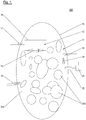
- the in the FIG. 1 illustrated tank device 100 comprises a pressure vessel 10, in the interior of which a first chamber 11 and a second chamber 12 are formed, of which the first chamber 11, the second chamber 12 substantially completely surrounds.
- the first and the second chamber are completed against each other, and they are connected by a separating them vibratable membrane 13 in operative connection.
- a pressure change in the first chamber 11 thus causes a reaction of the membrane (eg stretching in one or the other direction as indicated in the figure by the double arrow) and thereby a change in volume of the second chamber 12 and vice versa.
- an equilibrium state prevails, in which the same (equilibrium) pressure prevails in both chambers.
- the first chamber 11 is partially filled with a tank liquid 200 (for example cryogenic fuel, in particular for a rocket engine); In the illustrated situation, the tank device is under at least approximate weightlessness, therefore, the tank liquid 200 does not form a continuous liquid level, but is divided into a plurality of drops.
- the first chamber 11 contains a gas 300 (e.g., an inert gas such as helium or nitrogen or a gas derived from the liquid).
- the second chamber 12 is surrounded by a stable housing 16 and the membrane 13 and contains a gas (which may be, for example, helium and / or the same gas as the first chamber 11 contains).
- a gas which may be, for example, helium and / or the same gas as the first chamber 11 contains.
- a (preferably controllable) valve 17 gas can be supplied into the second chamber 12 and / or be discharged from it in the exemplary embodiment shown; when the valve is closed, the gas volume in the second chamber 12 is completed.
- a predetermined volume of the second chamber 12 can be adjusted by means of the valve 17 (eg after a gas supply or a gas release into or out of the first chamber) and thus a formation or a state of the membrane 13 is effected, the / at their Excitation allows an advantageous oscillation amplitude.
- gas could also be conducted from the first chamber 11 into the second chamber 12 by means of the valve 17.
- the second chamber contains an invariable amount (mass) of gas (e.g., helium), so does not include a valve 17.
- a (not shown) control of the valve 17 may be coupled to a (also not shown) control of at least one valve by means of which gas (eg for the purpose of expelling the tank liquid 200 from the pressure vessel) can be introduced into the first chamber or through the Gas 300 (eg, for effecting cooling) may be drained from the first chamber and / or adapted to cause a surge in the pressure vessel:
- gas eg for the purpose of expelling the tank liquid 200 from the pressure vessel
- Gas 300 eg, for effecting cooling
- the tank device 100 has such a valve 14, which according to the invention is adapted to effect such a pressure surge in the pressure vessel 10, e.g. by being opened and closed again for a predetermined pulse time (which may be for example at most 0.5 seconds, at most 0.2 seconds or even at most 0.1 seconds), so that gas 300 is introduced into the first chamber 11 through the opened valve 14 can penetrate or escape from it (depending on the applied pressure on both sides of the valve).
- a predetermined pulse time which may be for example at most 0.5 seconds, at most 0.2 seconds or even at most 0.1 seconds
- the tank device 100 shown in the figure further comprises a temperature sensor 18 for measuring a prevailing in the pressure vessel (in particular in the first chamber 11) temperature.
- a second temperature sensor may be arranged for temperature measurement in the chamber 12 (not shown here). In each case measured temperature values can be transmitted to the evaluation device 20 in the exemplary embodiment shown.
- a pressure sensor 15 is set up to measure the pressure that changes periodically during the pressure oscillation in the first chamber (several times in succession), thus to record the pressure oscillation (including an equilibrium pressure) in the first chamber 11 and to provide corresponding measured values to transmit an evaluation device 20.
- the pressure sensor can (eg as a piezoelectric sensor) also serve for excitation, so give a "ping" to the gas space.
- the evaluation device 20 is preferably configured to determine a gas volume in the pressure vessel 10 from the pressure oscillation or from the measured values describing the pressure oscillation and a (current) temperature measured with the temperature sensor 18, eg a volume of gas 300 in the first Chamber 11 and thus a volume of gas in the pressure vessel 10 in total.
- the evaluation device can also be set up to calculate a volume of tank liquid 200 in the pressure vessel 10 (in the first chamber 11), preferably from the previously determined gas volume. This calculation can take place, for example, taking into account a previously known interior volume of the pressure vessel and / or a volume of the first chamber 11 and / or the second chamber 12 adjusted after the pressure oscillation has subsided taking into account physical constants of the gas.
- the evaluation device 20 can also be set up to calculate a mass of the tank liquid 200 contained in the pressure vessel (namely in the first chamber 11) taking into account a (current) temperature measured by the temperature sensor 18 (for example, from its volume and density).
- the pressure surge valve 14 may preferably be connected or connected to a gas supply for expelling the tank liquid 200 from the pressure vessel into a supply line 19 leading to an engine, and / or to a gas outlet for effecting cooling of the tank liquid 200.
- valve 14 can perform other functions besides the effect of a pressure surge, so need not be additionally installed for the determination of the gas volume in the pressure vessel valve.
- a relatively simple construction of the tank device can be realized, which allows a low production cost and high robustness.
- the pressure sensor 15 and / or the temperature sensor 18 can / can be connected to a (not shown) control of a valve, through which a gas supply for expelling the tank liquid and / or a gas discharge for cooling can take place (such a valve as mentioned with the Valve 14 may be coincident to effect a surge in pressure).
- the pressure sensor and / or the temperature sensor can / can thus in addition to a contribution to the determination of a Gas volume in the pressure vessel each fulfill at least one additional function, for example, to control a respective required pressure and / or temperature levels in the pressure vessel.
- the tank device comprises a pressure vessel 10, in the interior of which a first chamber 11 for the tank liquid and second chamber 12 are arranged. First and second chambers are closed against each other and are operatively connected by at least one oscillating diaphragm 13 separating them.
- the housing 16 of the second chamber 12 may be secured inside the pressure vessel 10 or be part of the pressure vessel 10.
- the tank device further comprises a controllable member 14 for effecting a pressure surge in the pressure vessel 10, a pressure sensor 15 for detecting a pressure vibration resulting from the pressure surge, and a temperature sensor 18 for measuring a temperature prevailing in the pressure vessel.
- An evaluation device 20 of the tank device 100 is set up to determine a current gas volume in the pressure vessel 10 from a pressure oscillation detected in each case and a temperature measured with the temperature sensor 18. From this, the mass of the existing tank liquid 200 can be calculated.
Landscapes
- Engineering & Computer Science (AREA)
- Mechanical Engineering (AREA)
- General Engineering & Computer Science (AREA)
- Physics & Mathematics (AREA)
- Fluid Mechanics (AREA)
- General Physics & Mathematics (AREA)
- Chemical & Material Sciences (AREA)
- Combustion & Propulsion (AREA)
- Thermal Sciences (AREA)
- Filling Or Discharging Of Gas Storage Vessels (AREA)
Abstract
Description
- Die Erfindung betrifft eine Tankvorrichtung für eine Tankflüssigkeit, ein Verfahren zur Bestimmung eines (veränderlichen) Gasvolumens in einer Tankvorrichtung und eine Rakete mit einer Tankvorrichtung zum Einsatz im Weltraum.
- Die Menge einer Tankflüssigkeit in einem Tankbehälter wird üblicherweise durch die Höhe des jeweiligen Flüssigkeitsspiegels bestimmt. Bei Schrägstellungen, Geschwindigkeitsänderungen oder Vibrationen eines den Behälter umfassenden Fahrzeugs, Schiffes oder Flugzeugs ergeben sich aus einer derartigen Verfahrensweise Ungenauigkeiten in der Messung. Zudem setzt eine derartige kapazitative Füllstandsmessung eine zusammenhängende Grenzschicht (einen sogenannten Meniskus) zwischen Flüssigkeit und Gasphase sowie eine Anordnung der Flüssigkeit im unteren Teil des Tankbehälters voraus. Bei Tankbehältern von Weltraumraketen sind diese Voraussetzungen nur vor dem Start oder während der Brenndauer des Triebwerks erfüllt, denn nach Abschalten des Triebwerks im Weltraum (während sogenannter "Coasting-Phasen") wird die Flüssigkeit in der Schwerelosigkeit in verschiedene, voneinander durch Gas getrennte Bereiche separiert.
- Unterschiedliche Verfahren sind daher in der Diskussion, um das Flüssigkeitsvolumen auf alternative Weise bestimmen zu können:
Beispielsweise wird bei der optischen Absorptionsmessung der Tankbehälter mit einer Lichtquelle durch Mehrfachreflexion ausgeleuchtet. Dabei wird ein Teil der Lichtenergie infolge von Absorption des Lichtes in der Tankflüssigkeit in Wärme umgesetzt. Die verbleibende Lichtmenge wird gemessen und daraus indirekt das vorhandene Flüssigkeitsvolumen bestimmt. - Dieses Verfahren setzt voraus, dass das gesamte Tankvolumen durch Mehrfachreflexionen ausgeleuchtet ist und dass die gemessene Lichtintensität tatsächlich dem Mittelwert entspricht (der Tank muss wie eine Ulbricht-Kugel wirken). Das Messverfahren erfordert außerdem eine aufwendige optische Instrumentierung, die auch noch die hohen mechanischen und thermischen Anforderungen innerhalb einer Rakete erfüllen muss.
- Ein weiteres optisches Verfahren wurde von Ryan M. Sullenberger, Wesley M. Munoz, Matt P. Lyon, Kenny Vogel, Azer P. Yalin, Valentin Korman und Kurt A. Polzin in der Veröffentlichung "Optical Mass Gauging System for Measuring Liquid Levels in a Reduced Gravity Environment" (https://ntrs.nasa.gov/archive/nasa/casi.ntrs.../20100033282.pdf) beschrieben. Dieses Vorgehen ist jedoch technisch noch erheblich aufwendiger und empfindlicher, weil hier ein interferometrisches Verfahren eingesetzt wird.
- In der Druckschrift
DE 33 11 982 A1 werden eine Vorrichtung und ein Verfahren zur Bestimmung des Flüssigkeitsvolumens in einem geschlossenen Behälter offenbart. Die Vorrichtung umfasst dabei eine Membran, die wie eine Lautsprechermembran ausgebildet ist und an die von außen mittels elektromotorischer Mittel periodisch ein Impulses angelegt werden kann. Die Periode einer resultierenden Eigenschwingung der Membran kann dann erfasst und daraus ein Gas- und ein Flüssigkeitsvolumen berechnet werden. Die Vorrichtung und das Verfahren sind für Fahrzeuge ausgelegt und nicht für die Anwendung unter Schwerelosigkeit und mit extremen Druckänderungen konzipiert. - Die vorliegende Erfindung hat die Aufgabe, eine Technik zur Bestimmung eines veränderlichen Inhalts einer Tankvorrichtung unter Vermeidung der oben genannten Nachteile bereitzustellen, die sich insbesondere für eine Verwendung in Weltraumraketen eignet und dabei solide und einfach in der Installation ist.
- Die Aufgabe wird gelöst durch eine Tankvorrichtung gemäß Anspruch 1, eine Rakete nach Anspruch 8 und ein Verfahren gemäß Anspruch 9. Bevorzugte Ausführungsformen werden in den Unteransprüchen, der Beschreibung und den Figuren offenbart.
- Eine erfindungsgemäße Tankvorrichtung dient der Aufnahme bzw. Bereitstellung einer Tankflüssigkeit (die insbesondere kryogener Treibstoff sein kann). Sie umfasst einen Druckbehälter, in dessen Innerem eine erste Kammer und eine zweite Kammer ausgebildet sind. Als erste und zweite Kammer sind dabei zueinander disjunkte Volumenbereiche zu verstehen. Insbesondere kann die erste Kammer die zweite Kammer ganz oder teilweise umgeben, oder die zweite Kammer kann die erste Kammer ganz oder teilweise umgeben.
- Die erste Kammer ist dazu eingerichtet, die Tankflüssigkeit und/oder ein Bedrückungsgas aufzunehmen bzw. zu enthalten, das zum Austreiben der Tankflüssigkeit aus der ersten Kammer und/oder zur Regulierung einer Temperatur in der ersten Kammer zu- und/oder abgelassen werden kann. Ein derartiges Bedrückungsgas kann beispielsweise ein Inertgas wie Stickstoff oder Helium sein.
- Die zweite Kammer ist gegenüber der ersten Kammer abgeschlossen, ein Gas- oder Flüssigkeitsaustausch zwischen den Kammern ist also unmöglich.
- Dabei stehen die erste und die zweite Kammer durch mindestens eine sie trennende schwingfähige Membran in Wirkverbindung; eine Druckänderung in der ersten Kammer bewirkt somit eine Volumenänderung in der zweiten Kammer und umgekehrt, so dass sich jeweils ein Gleichgewichtszustand einstellt, in dem in beiden Kammern derselbe Druck herrscht (der hier auch als der Gleichgewichtsdruck bezeichnet wird).
- Die Tankvorrichtung weist zudem mindestens ein steuerbares Element zum Erzeugen eines Druckstoßes im Druckbehälter auf; der Druckstoß kann insbesondere in die erste Kammer oder aus der ersten Kammer gerichtet sein und/oder eine Pulszeit aufweisen, die beispielsweise höchstens 0,5 Sekunden, höchstens 0,2 Sekunden oder sogar höchstens 0,1 Sekunden betragen kann.
- Aufgrund der Wirkverbindung der ersten und der zweiten Kammer wird die Membran durch einen derartigen Druckstoß in eine Schwingung versetzt, was wiederum Druckschwingungen in der ersten und in der zweiten Kammer zur Folge hat. Ein Drucksensor der Tankvorrichtung ist dazu eingerichtet, eine derartige Druckschwingung in der ersten oder der zweiten Kammer zu erfassen, beispielsweise in Form einer Mehrzahl an zu verschiedenen Zeitpunkten (nacheinander) gemessenen Druckwerten. Auf diese Weise kann eine gedämpfte periodische Schwingung der Membran erfasst werden. Der Drucksensor kann als Piezoelement bzw. Piezosensor ausgebildet und/oder dazu eingerichtet sein, auch zum Bewirken des Druckstoßes bzw. zur Anregung einer Druckschwingung zu dienen; insbesondere kann das steuerbare Element den Drucksensor umfassen.
- Das steuerbare Element kann beispielsweise mindestens ein Piezoelement umfassen, das z.B. an einer Tankwand befestigt und/oder (ganz oder teilweise) in eine Tankwand eingebaut sein kann. Gemäß einer bevorzugten Ausführungsform umfasst das steuerbare Element ein steuerbares Ventil zur Gaszufuhr und/oder zum Gasauslass in die bzw. aus der ersten Kammer: Mittels eines derartigen Ventils kann somit der (Gas-)Druck in der ersten Kammer (bzw. im darin enthaltenen Gasraum) beeinflusst werden. Das steuerbare Ventil kann an eine Steuerung angeschlossen sein, die es zum Bewirken des Druckstoßes für eine vorbestimmte Pulszeit öffnet (und sogleich wieder schließt).
- Weiterhin weist eine erfindungsgemäße Tankvorrichtung einen oder mehrere Temperatursensor(en) zur Messung (jeweils) einer im Druckbehälter herrschenden Temperatur auf.
- Eine Auswertungseinrichtung der Tankvorrichtung ist dazu vorgesehen, aus einer erfassten Druckschwingung (z.B. aus deren sich aus den Messwerten ergebenden Frequenz und/oder Amplitude um einen sich einstellenden Gleichgewichtsdruck) und mindestens einer mit dem/den Temperatursensor/en gemessenen Temperatur ein Gasvolumen im Druckbehälter zu bestimmen, vorzugsweise mittels einer unter Berücksichtigung eines oder mehrerer physikalischer Eigenschaften bzw. spezifischen/spezifischer Parameter(s) des Gases bestimmten Funktionsvorschrift; als "Bestimmen eines Gasvolumens" wird dabei in dieser Schrift auch die Bestimmung eines Wertes verstanden, aus dem das Gasvolumen mittels einer bijektiven Funktionsvorschrift berechnet werden kann; Entsprechendes gilt (s.u.) für ein "Bestimmen eines Volumens einer Tankflüssigkeit".
- Das Gasvolumen kann das (zum Zeitpunkt der Bestimmung aktuelle) Volumen des Gases in der ersten Kammer und/oder im Druckbehälter (insgesamt) sein.
- Die Auswertungseinrichtung kann ferner dazu eingerichtet sein, das Volumen der im Druckbehälter bzw. in der ersten Kammer (aktuell) enthaltenen Tankflüssigkeit zu bestimmen, beispielsweise aus dem bestimmten Gasvolumen, vorzugsweise unter Berücksichtigung eines vorbekannten Innenraumvolumens des Druckbehälters eines sich nach einem Abklingen der Druckschwingung eingestellten Volumens der ersten und/oder der zweiten Kammer.
- Eine erfindungsgemäße Rakete ist dazu eingerichtet, im Weltraum eingesetzt zu werden, vorzugsweise von der Erde ins Weltall zu fliegen. Sie umfasst mindestens ein Triebwerk sowie zu dessen Versorgung mit Treibstoff mindestens eine erfindungsgemäße Tankvorrichtung gemäß einer der in dieser Schrift offenbarten Ausführungsformen.
- Ein erfindungsgemäßes Verfahren dient der Bestimmung eines (veränderlichen, bei Durchführung des Verfahrens aktuellen) Gasvolumens in einem Druckbehälter einer Tankvorrichtung. Der Druckbehälter weist dabei eine erste Kammer für eine Tankflüssigkeit (die insbesondere kryogener Treibstoff sein kann) sowie eine zweite Kammer auf. Erste und zweite Kammer sind disjunkte Volumenbereiche (insbesondere kann die erste Kammer die zweite Kammer ganz oder teilweise umgeben oder umgekehrt). Sie sind gegeneinander abgeschlossen und stehen (wie oben beschrieben) durch mindestens eine sie trennende schwingfähige Membran in Wirkverbindung, so dass also eine Druckänderung in der ersten Kammer eine Volumenänderung der zweiten Kammer bewirkt und umgekehrt, bis sich jeweils ein Gleichgewichtszustand einstellt, in dem in beiden Kammern derselbe Druck herrscht (der hier auch als der Gleichgewichtsdruck bezeichnet wird).
- Das Verfahren umfasst ein Messen einer Temperatur im Druckbehälter sowie ein Anregen einer Druckschwingung in der ersten Kammer mittels eines steuerbaren Elements, das beispielsweise ein (z.B. an einer Tankwand befestigtes oder (ganz oder teilweise) in eine Tankwand eingebautes) Piezoelement und/oder mindestens ein steuerbares Ventil umfassen kann. Insbesondere kann das Anregen der Druckschwingung ein (schlagartiges) Zuführen und/oder Ablassen von Gas in die bzw. aus der ersten Kammer durch ein derartiges Ventil des Druckbehälters umfassen. Wie oben beschrieben kann das Anregen insbesondere ein Öffnen eines solchen Ventils für eine vorbestimmte Pulszeit umfassen (die beispielsweise höchstens 0,5 Sekunden, höchstens 0,2 Sekunden oder sogar höchstens 0,1 Sekunden betragen kann). Alternativ oder zusätzlich kann das Anregen der Druckschwingung mittels mindestens eines Impulses eines umfassten Piezoelements erfolgen.
- Dem erfindungsgemäßen Verfahren zufolge wird die Druckschwingung in der ersten und/oder zweiten Kammer erfasst, beispielsweise in Form einer Mehrzahl an nacheinander gemessenen Druckwerten. Aus der erfassten Druckschwingung und der gemessenen Temperatur wird ein Gasvolumen im Druckbehälter bestimmt; das Gasvolumen kann insbesondere das (zum Zeitpunkt der Bestimmung aktuelle) Volumen des Gases in der ersten Kammer und/oder im Druckbehälter (insgesamt) sein.
- Vorzugsweise erfolgt das Bestimmen mittels einer unter Berücksichtigung eines oder mehrerer physikalischer Eigenschaften bzw. spezifischen/spezifischer Parameter(s) des Gases bestimmten Funktionsvorschrift.
- Gemäß einer vorteilhaften Ausführungsform umfasst das Verfahren zudem das Bestimmen des Volumens der im Druckbehälter (in der ersten Kammer) enthaltenen Tankflüssigkeit, beispielsweise unter Berücksichtigung eines vorbekannten Innenraumvolumens des Druckbehälters und/oder eines sich nach einem Abklingen der Druckschwingung eingestellten Volumens der ersten und/oder der zweiten Kammer.
- Insbesondere eignet sich das erfindungsgemäße Verfahren zur Bestimmung eines Gasvolumens im Druckbehälter einer erfindungsgemäßen Tankvorrichtung gemäß einer der in dieser Schrift offenbarten Ausführungsformen.
- Eine erfindungsgemäße Tankvorrichtung, eine erfindungsgemäße Rakete und ein erfindungsgemäßes Verfahren ermöglichen eine zuverlässige Bestimmung eines Tankinhalts auch unabhängig von äußeren Bedingungen, beispielsweise von Erschütterungen, Beschleunigung oder Abbremsung der Tankvorrichtung und vom Einfluss der Gravitationskraft. Erfindungsgemäß kann dabei ein jeweils aktuelles Gasvolumen im Druckbehälter bestimmt werden, indem das zusammen mit der Tankflüssigkeit in der ersten Kammer befindliche Gas gezielt angeregt sowie anschließend ein durch diese Anregung induziertes transientes Antwortverhalten in Form von Druckschwankungen in der ersten bzw. der zweiten Kammer gemessen und ausgewertet wird. Die dazu erforderlichen bzw. dabei eingebundenen technischen Mittel sind robust und mit geringem Aufwand zu installieren.
- Die erfindungsgemäß mögliche präzise Ermittlung der Restflüssigkeit im Druckbehälter insbesondere am Ende einer Mission ermöglicht zudem eine genauere Modellbildung für zukünftige Missionen, die eine Verringerung der Sicherheitszuschläge bei den zu tankenden Flüssigkeiten und damit eine Masseneinsparung erlaubt.
- Vorzugsweise umfasst eine erfindungsgemäße Vorrichtung eine gasdurchlässige Abschirmungseinrichtung, die dazu eingerichtet ist, einen Kontakt der Membran mit Tankflüssigkeit in der ersten Kammer zu verhindern oder zumindest zu reduzieren. Analog ist die Membran bei einem erfindungsgemäßen Verfahren an einer der ersten Kammer zugewandten Seite vorzugsweise mindestens teilweise frei (also unbedeckt) von Tankflüssigkeit. Auf diese Weise kann ein optimales Schwingungsverhalten der Membran gewährleistet werden.
- Gemäß einer vorteilhaften Ausführungsform der vorliegenden Erfindung umfasst das steuerbare Element zum Bewirken des Druckstoßes ein steuerbares Ventil, das (zudem) an eine Gaszufuhr zum Austreiben der Tankflüssigkeit aus dem Druckbehälter (beispielsweise zum Triebwerk) und/oder an einen Gasauslass zur Druckregelung im Druckbehälter, beispielsweise zum Bewirken einer Kühlung der Tankflüssigkeit, angeschlossen ist. Somit kann das Ventil eine Mehrfachfunktion erfüllen, so dass die Volumenbestimmung also kein eigenes, separates Ventil als zusätzliches Bauteil erfordert. Die Tankvorrichtung kann dadurch besonders schlicht und robust gehalten werden.
- Analog kann der Drucksensor zum Erfassen der Druckschwingung Teil einer Druckregelungsvorrichtung der Tankvorrichtung zur Regelung eines Innendrucks im Druckbehälter sein, was ebenfalls eine erforderliche Komplexität und damit einen Herstellungsaufwand für die Tankvorrichtung minimiert und eine hohe Robustheit ermöglicht.
- Die zweite Kammer kann nach einem einmaligen Befüllen mit Gas (beispielsweise bevor eine Rakete, welche die Tankvorrichtung umfasst, gestartet wird) unter einem festgelegten Druck versiegelt sein, so dass dann die in der zweiten Kammer befindliche Masse an Gas also nicht mehr geändert wird. Das Gas kann insbesondere Helium sein oder umfassen.
- Alternativ kann die Tankvorrichtung ein Ventil aufweisen, durch das Gas in die zweite Kammer eingeleitet und/oder aus der zweiten Kammer abgelassen werden kann. Dieses Ventil, das in dieser Schrift auch als "zweites" Ventil bezeichnet wird, ermöglicht dann eine Einstellung eines für die Erhaltung der Schwingfähigkeit der Membran optimalen Volumens der zweiten Kammer, beispielsweise nach einer Gaszufuhr in die oder einem Gasablassen aus der ersten Kammer, vorzugsweise während einer (zumindest im Wesentlichen) schwingungsfreien Phase der Membran. Die Tankvorrichtung kann einen Drucksensor zur Messung eines Drucks in der zweiten Kammer umfassen und/oder eine Steuerungseinrichtung zur Steuerung eines solchen zweiten Ventils. Eine solche Steuerungseinrichtung des zweiten Ventils kann dazu eingerichtet sein, mit einer Steuerungseinrichtung zur Steuerung eines (ersten) Ventils zur Gaszufuhr oder zum Gasablassen in die bzw. aus der ersten Kammer zu kommunizieren (das wie erwähnt insbesondere mit dem genannten Ventil zum Bewirken eines Druckstoßes übereinstimmen kann), oder die Tankvorrichtung kann eine gemeinsame Steuerungseinrichtung zur Steuerung beider genannter Ventile umfassen.
- Entsprechend umfasst eine vorteilhafte Ausführungsvariante eines erfindungsgemäßen Verfahrens ein Einrichten (also Bewirken) eines Volumens der zweiten Kammer, beispielsweise durch ein Zuführen oder Ablassen von Gas durch ein (zweites) Ventil in die bzw. aus der zweite(n) Kammer. Das Einrichten kann eine Messen eines Drucks in der zweiten Kammer umfassen und/oder insbesondere nach einer Gaszufuhr (z.B. zum Austreiben der Tankflüssigkeit aus dem Druckbehälter) oder einem Gasablassen (z.B. zum Bewirken einer Kühlung) in die bzw. aus der erste(n) Kammer erfolgen und/oder während einer (zumindest im Wesentlichen) schwingungsfreien Phase der Membran.
- Vorzugsweise ist die Auswertungseinheit einer erfindungsgemäßen Tankvorrichtung dazu eingerichtet, aus einem bestimmten Gasvolumen bzw. einem daraus berechneten Volumen an Tankflüssigkeit im Druckbehälter sowie einer gemessenen Temperatur im Druckbehälter die Masse an Tankflüssigkeit im Druckbehälter zu bestimmen; als "Bestimmen der Masse" wird dabei in dieser Schrift auch die Bestimmung eines Wertes verstanden, aus dem die Masse mittels einer bijektiven Funktionsvorschrift berechnet werden kann. Entsprechend umfasst ein erfindungsgemäßes Verfahren vorzugsweise ein derartiges Bestimmen der Masse an Tankflüssigkeit im Druckbehälter.
- Eine Steuerung eines Triebwerks (das beispielsweise Teil einer erfindungsgemäßen Rakete sein kann) kann dann dazu eingerichtet sein, das Triebwerk in Abhängigkeit von der bestimmten Masse an Treibstoff im Druckbehälter zu zünden bzw. (ggf.) dessen Zündung zu unterbinden und/oder ein Verhältnis von Treibstoff zu einer Oxidatormenge im Druckbehälter abhängig vom Füllstand des Druckbehälters (insbesondere während des Fluges) zu ändern. So kann eine Zündung ohne ausreichende Treibstoff- bzw. Oxidatormengen und die damit verbundene Gefahr einer Explosion vermieden werden, bzw. es kann während des Fluges ein optimales Treibstoff/Oxidatorverhältnis eingestellt werden.
- Gemäß einer vorteilhaften Ausführungsform wird das Anregen der Druckschwingung in einem erfindungsgemäßen Verfahren unter Schwerelosigkeit, unter Mikro-Gravitationsbedingung (insbesondere jenseits der Erdatmosphäre beispielsweise nach Abschalten mindestens eines Triebwerkes) und/oder während einer Beschleunigung einer die Tankvorrichtung enthaltenden Rakete durchgeführt.
- Im Folgenden wird ein bevorzugtes Ausführungsbeispiel der Erfindung anhand einer Zeichnung näher erläutert. Es versteht sich, dass eine erfindungsgemäße Tankvorrichtung nicht alle der gezeigten Komponenten aufweisen muss bzw. weitere Elemente enthalten kann.
-
- Figur 1
- eine Tankvorrichtung gemäß einer exemplarischen Ausführungsform der vorliegenden Erfindung.
- Die in der
Figur 1 dargestellte Tankvorrichtung 100 umfasst einen Druckbehälter 10, in dessen Innerem eine erste Kammer 11 und eine zweite Kammer 12 ausgebildet sind, von denen die erste Kammer 11 die zweite Kammer 12 im Wesentlichen vollständig umgibt. Die erste und die zweite Kammer sind dabei gegeneinander abgeschlossen, und sie stehen durch eine sie trennende schwingfähige Membran 13 in Wirkverbindung. Eine Druckänderung in der ersten Kammer 11 bewirkt somit eine Reaktion der Membran (z.B. Dehnung in die eine oder andere Richtung wie in der Figur durch den Doppelpfeil angedeutet) und dadurch eine Volumenänderung der zweiten Kammer 12 und umgekehrt. Auf die Dauer stellt sich jeweils ein Gleichgewichtszustand ein, in dem in beiden Kammern derselbe (Gleichgewichts-)Druck herrscht. - Die erste Kammer 11 ist teilweise mit einer Tankflüssigkeit 200 (beispielsweise kryogenem Treibstoff, insbesondere für ein Raketentriebwerk) gefüllt; in der dargestellten Situation befindet sich die Tankvorrichtung unter mindestens annähernder Schwerelosigkeit, daher bildet die Tankflüssigkeit 200 keinen zusammenhängenden Flüssigkeitsspiegel aus, sondern ist in eine Vielzahl an Tropfen aufgeteilt. Neben der Tankflüssigkeit 200 enthält die erste Kammer 11 ein Gas 300 (z.B. ein Inertgas wie Helium oder Stickstoff bzw. ein aus der Flüssigkeit stammendes Gas).
- Die zweite Kammer 12 ist von einem stabilen Gehäuse 16 und der Membran 13 umgeben und enthält ein Gas (das z.B. Helium und/oder dasselbe Gas sein kann, wie es die erste Kammer 11 enthält). Durch ein (vorzugsweise steuerbares) Ventil 17 kann im gezeigten Ausführungsbeispiel Gas in die zweite Kammer 12 zugeführt und/oder aus ihr abgelassen werden; bei geschlossenem Ventil ist das Gasvolumen in der zweiten Kammer 12 abgeschlossen. Insbesondere kann mittels des Ventils 17 (z.B. nach einer Gaszufuhr oder einem Gasablassen in die bzw. aus der ersten Kammer) ein vorbestimmtes Volumen der zweiten Kammer 12 eingestellt und damit eine Ausformung bzw. ein Zustand der Membran 13 bewirkt werden, die/der bei deren Anregung eine vorteilhafte Schwingungsamplitude ermöglicht. Außerdem könnte mittels des Ventils 17 auch Gas aus der ersten Kammer 11 in die zweite Kammer 12 geleitet werden. Gemäß einer alternativen (nicht gezeigten) Ausführungsform enthält die zweite Kammer nach einem Befüllen und Versiegeln eine unveränderliche Menge (Masse) an Gas (z.B. Helium), umfasst also kein Ventil 17.
- Eine (nicht dargestellte) Steuerung des Ventils 17 kann mit einer (ebenfalls nicht dargestellten) Steuerung mindestens eines Ventils gekoppelt sein, mittels dessen Gas (z.B. zum Zwecke des Austreibens der Tankflüssigkeit 200 aus dem Druckbehälter) in die erste Kammer eingeleitet werden kann oder durch das Gas 300 (z.B. zum Bewirken einer Kühlung) aus der ersten Kammer abgelassen werden kann und/oder das dazu eingerichtet ist, einen Druckstoß im Druckbehälter zu bewirken:
- Die Tankvorrichtung 100 weist ein solches Ventil 14 auf, das erfindungsgemäß dazu eingerichtet ist, einen derartigen Druckstoß im Druckbehälter 10 zur bewirken, z.B. indem es für eine vorgegebene Pulszeit (die beispielsweise höchstens 0,5 Sekunden, höchstens 0,2 Sekunden oder sogar höchstens 0,1 Sekunden betragen kann) geöffnet und wieder geschlossen wird, so dass durch das geöffnete Ventil 14 Gas 300 in die erste Kammer 11 eindringen oder aus ihr austreten kann (je nach anliegendem Druck auf beiden Seiten des Ventils). Da die in den Kammern 11 und 12 eingeschlossenen Gase zusammen mit der eine Masse aufweisenden Membran 13 innerhalb des geschlossenen Druckbehälters 10 ein schwingfähiges System bilden, hat ein derartiger Druckstoß eine Schwingung der Membran 13 und damit je eine Druckschwingung in der ersten und der zweiten Kammer zur Folge (wobei die Druckschwingungsamplituden in den beiden Kammern zueinander komplementär sind).
- Die in der Figur gezeigte Tankvorrichtung 100 umfasst ferner einen Temperatursensor 18 zur Messung einer im Druckbehälter (insbesondere in der ersten Kammer 11) herrschenden Temperatur. Ein zweiter Temperatursensor kann zur Temperaturmessung in der Kammer 12 angeordnet sein (hier nicht gezeichnet). Jeweils gemessene Temperaturwerte können im dargestellten Ausführungsbeispiel an die Auswertungseinrichtung 20 übermittelt werden.
- Ein Drucksensor 15 ist im dargestellten Beispiel dazu eingerichtet, den sich während der Druckschwingung in der ersten Kammer periodisch ändernden Druck (mehrmals nacheinander) zu messen, so die Druckschwingung (einschließlich eines sich einstellenden Gleichgewichtsdrucks) in der ersten Kammer 11 zu erfassen und zugehörige Messwerte an eine Auswertungseinrichtung 20 zu übermitteln. Der Drucksensor kann (z.B. als Piezosensor) auch zur Anregung dienen, also ein "Ping" an den Gasraum geben. Die Auswertungseinrichtung 20 ist vorzugsweise dazu eingerichtet, aus der Druckschwingung, bzw. aus den erhaltenen, die Druckschwingung beschreibenden Messwerten sowie einer mit dem Temperatursensor 18 gemessenen (aktuellen) Temperatur ein Gasvolumen im Druckbehälter 10 zu bestimmen, z.B. ein Volumen an Gas 300 in der ersten Kammer 11 und somit ein Volumen an Gas im Druckbehälter 10 insgesamt. Die Auswertungseinrichtung kann ferner dazu eingerichtet sein, ein Volumen an Tankflüssigkeit 200 im Druckbehälter 10 (in der ersten Kammer 11) zu berechnen, vorzugsweise aus dem zuvor bestimmten Gasvolumen. Diese Berechnung kann beispielsweise unter Berücksichtigung eines vorbekannten Innenraumvolumens des Druckbehälters und/oder eines sich nach einem Abklingen der Druckschwingung eingestellten Volumens der ersten Kammer 11 und/oder der zweiten Kammer 12 unter Berücksichtigung physikalischer Konstanten des Gases erfolgen.
- Die Auswertungseinrichtung 20 kann zudem dazu eingerichtet sein, unter Berücksichtigung einer vom Temperatursensor 18 gemessenen (aktuellen) Temperatur eine Masse der im Druckbehälter (nämlich in der ersten Kammer 11) enthaltenen Tankflüssigkeit 200 zu berechnen (beispielsweise aus deren Volumen und Dichte).
- Das Ventil 14 zum Bewirken eines Druckstoßes kann vorzugsweise an eine Gaszufuhr zum Austreiben der Tankflüssigkeit 200 aus dem Druckbehälter in eine zu einem Triebwerk führende Zuleitung 19 angeschlossen oder anzuschließen sein, und/oder an einen Gasauslass zum Bewirken einer Kühlung der Tankflüssigkeit 200.
- Somit kann das Ventil 14 außer dem Bewirken eines Druckstoßes weitere Funktionen erfüllen, muss also kein zusätzlich für die Bestimmung des Gasvolumens im Druckbehälter installiertes Ventil sein. Damit kann ein relativ einfacher Aufbau der Tankvorrichtung realisiert werden, der einen geringen Herstellungsaufwand und eine hohe Robustheit ermöglicht.
- Der Drucksensor 15 und/oder der Temperatursensor 18 können/kann mit einer (nicht gezeigten) Steuerung eines Ventils verbunden sein, durch das eine Gaszufuhr zum Austreiben der Tankflüssigkeit und/oder ein Gasablassen zur Kühlung erfolgen kann (wobei ein derartiges Ventil wie erwähnt mit dem Ventil 14 zum Bewirken eines Druckstoßes übereinstimmen kann). Der Drucksensor und/oder der Temperatursensor können/kann also neben einem Beitragen zur Bestimmung eines Gasvolumens im Druckbehälter jeweils mindestens eine weitere Funktion erfüllen, beispielsweise zur Regelung eines jeweils erforderlichen Druck- und/oder Temperaturniveaus im Druckbehälter.
- Offenbart ist eine Tankvorrichtung 100 für eine Tankflüssigkeit 200. Die Tankvorrichtung umfasst einen Druckbehälter 10, in dessen Innerem eine erste Kammer 11 für die Tankflüssigkeit und zweite Kammer 12 angeordnet sind. Erste und zweite Kammer sind gegeneinander abgeschlossen und stehen durch mindestens eine sie trennende schwingfähige Membran 13 in Wirkverbindung. Das Gehäuse 16 der zweiten Kammer 12 kann innen am Druckbehälter 10 befestigt oder Teil des Druckbehälters 10 sein. Die Tankvorrichtung umfasst ferner ein steuerbares Element 14 zum Bewirken eines Druckstoßes im Druckbehälter 10, einen Drucksensor 15 zur Erfassung einer aus dem Druckstoß resultierenden Druckschwingung und einen Temperatursensor 18 zum Messen einer im Druckbehälter herrschenden Temperatur. Eine Auswertungseinrichtung 20 der Tankvorrichtung 100 ist dazu eingerichtet, aus einer jeweils erfassten Druckschwingung und einer mit dem Temperatursensor 18 gemessenen Temperatur ein aktuelles Gasvolumen im Druckbehälter 10 zu bestimmen. Daraus kann die Masse der vorhandenen Tankflüssigkeit 200 berechnet werden.
- Offenbart sind ferner eine Rakete zum Einsatz im Weltraum und ein Verfahren zur Bestimmung eines (veränderlichen) Gasvolumens in einem Druckbehälter einer Tankvorrichtung.
-
- 10 Druckbehälter
- 11 erste Kammer
- 12 zweite Kammer
- 13 Membran
- 14 Ventil zum Bewirken eines Druckstoßes
- 15 Drucksensor
- 16 Gehäuse der zweiten Kammer 12
- 17 Ventil zur Gaszufuhr und/oder zum Gasablassen in die bzw. aus der zweiten Kammer 12
- 18 Temperatursensor
- 19 Zuleitung zum Triebwerk
- 20 Auswertungseinrichtung
- 100 Tankvorrichtung
- 200 Tankflüssigkeit
- 300 Gas
Claims (15)
- Tankvorrichtung (100) für eine Tankflüssigkeit, wobei die Tankvorrichtung aufweist:- einen Druckbehälter (10), in dessen Innerem eine erste Kammer (11) für die Tankflüssigkeit (200) und eine zweite Kammer (12) ausgebildet sind, wobei die erste und die zweite Kammer gegeneinander abgeschlossen sind und durch mindestens eine sie trennende schwingfähige Membran (13) in Wirkverbindung stehen;- mindestens ein steuerbares Element (14) zum Bewirken eines Druckstoßes im Druckbehälter;- einen Drucksensor (15) zur Erfassung einer aus dem Druckstoß resultierenden Druckschwingung in der ersten und/oder zweiten Kammer;- einen Temperatursensor (18) zum Messen einer Temperatur im Druckbehälter (10) und- eine Auswertungseinrichtung (20) zum Bestimmen eines Gasvolumens im Druckbehälter (10) aus einer erfassten Druckschwingung und einer gemessenen Temperatur.
- Tankvorrichtung nach Anspruch 1, wobei das steuerbare Element ein steuerbares Ventil umfasst, durch das zum Bewirken eines Druckstoßes Gas in die erste Kammer eingelassen und/oder aus der ersten Kammer abgelassen werden kann.
- Tankvorrichtung nach Anspruch 2, wobei das steuerbare Ventil (14) an eine Gaszufuhr zum Austreiben der Tankflüssigkeit aus dem Druckbehälter (10) oder an einen Gasauslass zur Druckregelung, insbesondere zum Bewirken einer Kühlung der Tankflüssigkeit angeschlossen ist.
- Tankvorrichtung nach einem der vorhergehenden Ansprüche, die zudem ein Ventil (17) zur Gaszufuhr und/oder zum Gasauslass in die bzw. aus der zweiten Kammer (12) aufweist.
- Tankvorrichtung gemäß einem der vorhergehenden Ansprüche, wobei die Auswertungseinrichtung (20) ferner dazu eingerichtet ist, ein Volumen an Tankflüssigkeit (300) im Druckbehälter (10) zu bestimmen.
- Tankvorrichtung gemäß einem der vorhergehenden Ansprüche, wobei die Auswertungseinrichtung (20) ferner dazu eingerichtet ist, eine Masse an Tankflüssigkeit (200) in der ersten Kammer (10) zu bestimmen.
- Tankvorrichtung gemäß einem der vorhergehenden Ansprüche, wobei die Tankflüssigkeit (200) ein kryogener Treibstoff ist.
- Tankvorrichtung gemäß einem der vorstehenden Ansprüche, wobei der Drucksensor (15) als Piezosensor ausgebildet und/oder dazu eingerichtet ist, zur Anregung zu dienen.
- Tankvorrichtung gemäß einem der vorstehenden Ansprüche, wobei ein Gehäuse (16) der zweiten Kammer innen am Druckbehälter (10) befestigt oder Teil des Druckbehälters (10) ist.
- Rakete zum Einsatz im Weltraum, die ein Triebwerk sowie zu dessen Versorgung mit Treibstoff wenigstens eine Tankvorrichtung gemäß einem der vorhergehenden Ansprüche aufweist.
- Verfahren zur Bestimmung eines Gasvolumens in einem Druckbehälter (10) einer Tankvorrichtung, wobei der Druckbehälter eine erste Kammer (11) für eine Tankflüssigkeit (200) sowie eine zweite Kammer (12) aufweist, wobei die erste und die zweite Kammer gegeneinander abgeschlossen sind und durch mindestens eine sie trennende schwingfähige Membran (13) in Wirkverbindung stehen, und wobei das Verfahren umfasst:- anregen einer Druckschwingung in der ersten Kammer (11) mittels eines Impulses von einem Piezoelement und/oder durch Zuführen und/oder Ablassen von Gas (300) in die bzw. aus der ersten Kammer durch ein steuerbares Ventil (14) des Druckbehälters;- erfassen einer Druckschwingung in der ersten und/oder zweiten Kammer;- messen einer Temperatur im Druckbehälter; und- bestimmen des Gasvolumens im Druckbehälter (10) aus einer erfassten Druckschwingung und einer gemessenen Temperatur.
- Verfahren gemäß Anspruch 11, das zudem ein Bestimmen eines Volumens an Tankflüssigkeit (200) in der ersten Kammer (11)und/oder ein Bestimmen einer Masse der Tankflüssigkeit (200) in der ersten Kammer (11) umfasst.
- Verfahren gemäß einem der Ansprüche 11 oder 12, das zudem vor dem Anregen der Druckschwingung ein Einrichten eines Volumens der zweiten Kammer (12) umfasst.
- Verfahren gemäß einem der Ansprüche 11 bis 13, wobei das Anregen der Druckschwingung unter Schwerelosigkeit, Mikro-Gravitationsbedingung und/oder während einer Beschleunigung einer die Tankvorrichtung enthaltenen Rakete durchgeführt wird.
- Verfahren gemäß einem der Ansprüche 11 bis 14, wobei die Tankflüssigkeit (200) ein kryogener Treibstoff ist.
Applications Claiming Priority (1)
| Application Number | Priority Date | Filing Date | Title |
|---|---|---|---|
| DE102017115166.4A DE102017115166A1 (de) | 2017-07-06 | 2017-07-06 | Bestimmung eines Gasvolumens in einer Tankvorrichtung |
Publications (3)
| Publication Number | Publication Date |
|---|---|
| EP3425349A2 true EP3425349A2 (de) | 2019-01-09 |
| EP3425349A3 EP3425349A3 (de) | 2019-01-30 |
| EP3425349B1 EP3425349B1 (de) | 2021-05-05 |
Family
ID=62816344
Family Applications (1)
| Application Number | Title | Priority Date | Filing Date |
|---|---|---|---|
| EP18180347.9A Active EP3425349B1 (de) | 2017-07-06 | 2018-06-28 | Bestimmung eines gasvolumens in einer tankvorrichtung |
Country Status (6)
| Country | Link |
|---|---|
| US (1) | US10865944B2 (de) |
| EP (1) | EP3425349B1 (de) |
| JP (1) | JP2019015402A (de) |
| CN (1) | CN109211351A (de) |
| DE (1) | DE102017115166A1 (de) |
| RU (1) | RU2018124605A (de) |
Cited By (1)
| Publication number | Priority date | Publication date | Assignee | Title |
|---|---|---|---|---|
| CN113386981A (zh) * | 2021-06-07 | 2021-09-14 | 上海空间推进研究所 | 一种波纹式锥柱形隔膜贮箱 |
Families Citing this family (3)
| Publication number | Priority date | Publication date | Assignee | Title |
|---|---|---|---|---|
| US11402311B2 (en) * | 2019-11-25 | 2022-08-02 | Anton Paar Quantatec, Inc. | Pycnometer with acclimation chamber |
| CN111256775B (zh) * | 2020-02-25 | 2021-05-28 | 兰州大学 | 一种快速确定有效体积的同化箱系统及使用方法 |
| DE102024107425A1 (de) * | 2024-03-15 | 2025-09-18 | Bayerische Motoren Werke Aktiengesellschaft | Fortbewegungsmittel und Vorrichtung zur Ermittlung eines Flüssigkeitsvolumens einer Flüssigkeit in einem Tank |
Family Cites Families (8)
| Publication number | Priority date | Publication date | Assignee | Title |
|---|---|---|---|---|
| US3596510A (en) * | 1970-02-04 | 1971-08-03 | Nasa | Resonant infrasonic gauging apparatus |
| CH647596A5 (fr) | 1982-04-01 | 1985-01-31 | Battelle Memorial Institute | Procede pour determiner le volume de liquide contenu dans un recipient ferme et dispositif pour la mise en oeuvre de ce procede. |
| DE3540768C1 (de) * | 1985-11-16 | 1987-04-16 | Walter Nicolai | Verfahren und Vorrichtung zur Ermittlung und Anzeige der Menge eines fluessigen oder festen Lagerguts |
| JP4905619B2 (ja) * | 2001-06-21 | 2012-03-28 | 独立行政法人産業技術総合研究所 | 微小重力用体積計測装置 |
| FR2871441B1 (fr) * | 2004-06-10 | 2006-09-15 | Eads Astrium Sas Soc Par Actio | Procedes de detection de la vidange complete d'un reservoir d'ergol et de gestion d'ergol a bord d'un satellite |
| FR2969986B1 (fr) * | 2011-01-03 | 2013-10-04 | Centre Nat Etd Spatiales | Augmentation d'un systeme de propulsion monoergol |
| DE102014109836A1 (de) * | 2014-07-14 | 2016-01-14 | Hella Kgaa Hueck & Co. | Verfahren und Vorrichtung zum Bestimmen eines Volumens eines Nutzmediums in einem Vorratsbehälter |
| DE102014011652A1 (de) * | 2014-08-11 | 2016-02-11 | Memotec GmbH | Verfahren und Vorrichtung zum Bestimmen des Füllgrades eines geschlossenen Behälters |
-
2017
- 2017-07-06 DE DE102017115166.4A patent/DE102017115166A1/de not_active Withdrawn
-
2018
- 2018-06-28 EP EP18180347.9A patent/EP3425349B1/de active Active
- 2018-07-03 US US16/026,255 patent/US10865944B2/en active Active
- 2018-07-05 RU RU2018124605A patent/RU2018124605A/ru not_active Application Discontinuation
- 2018-07-05 JP JP2018128164A patent/JP2019015402A/ja active Pending
- 2018-07-06 CN CN201810736331.XA patent/CN109211351A/zh not_active Withdrawn
Cited By (2)
| Publication number | Priority date | Publication date | Assignee | Title |
|---|---|---|---|---|
| CN113386981A (zh) * | 2021-06-07 | 2021-09-14 | 上海空间推进研究所 | 一种波纹式锥柱形隔膜贮箱 |
| CN113386981B (zh) * | 2021-06-07 | 2022-09-27 | 上海空间推进研究所 | 一种波纹式锥柱形隔膜贮箱 |
Also Published As
| Publication number | Publication date |
|---|---|
| EP3425349B1 (de) | 2021-05-05 |
| DE102017115166A1 (de) | 2019-01-10 |
| US20190011085A1 (en) | 2019-01-10 |
| RU2018124605A (ru) | 2020-01-14 |
| EP3425349A3 (de) | 2019-01-30 |
| CN109211351A (zh) | 2019-01-15 |
| US10865944B2 (en) | 2020-12-15 |
| JP2019015402A (ja) | 2019-01-31 |
Similar Documents
| Publication | Publication Date | Title |
|---|---|---|
| EP3425349B1 (de) | Bestimmung eines gasvolumens in einer tankvorrichtung | |
| EP3298266B1 (de) | Vorrichtung zur messung der einspritzrate sowie messverfahren | |
| EP1336083B1 (de) | Verfahren und vorrichtung zur feststellung und/oder überwachung des füllstandes eines mediums in einem behälter bzw. zur ermittlung der dichte eines mediums in einem behälter | |
| DE19757655C2 (de) | Verfahren und Vorrichtung zur Funktionsüberwachung eines Drucksensors | |
| EP0432143B1 (de) | Verfahren und Verwendung einer Anordnung zur Prüfung mindestens eines Hohlkörpers auf sein Volumenverhalten | |
| EP0223048B1 (de) | Messanordnung zum Messen der Veränderung einer Flüssigkeitsmenge, insbesondere der Ölmenge in einer Brennkraftmaschine | |
| DE102011111610B4 (de) | Kalibrierung von allen Druckwandlern in einem Wasserstoffspeichersystem | |
| DE2227703C2 (de) | Schiffssteueranlage | |
| DE3914637A1 (de) | Fluessigkeitsbehaelter mit hydrostatischem fuellstandsmesser | |
| DE2715691A1 (de) | Hubschraubernavigationsgeraet | |
| EP3867035B1 (de) | Verfahren zum imprägnieren von polymergranulat | |
| WO2009033472A2 (de) | Windenergieanlage und verfahren zum betreiben einer windenergieanlage | |
| DE102016109424B4 (de) | Messmodul mit Feder-Masse-System zur Gewichtsermittlung | |
| DE102016206106A1 (de) | Speichervorrichtung für Wasserstoffträgermedium, Anlage umfassend eine derartige Speichervorrichtung und Verfahren zum Speichern von Wasserstoffträgermedium | |
| DE3873927T2 (de) | Elektronische steueranordnung. | |
| EP2004979B1 (de) | Verfahren zur bestimmung der treibstoffmasse eines raumflugkörpers | |
| EP3390808B1 (de) | Verfahren und vorrichtung zur bestimmung der einspritzrate eines einspritzventils | |
| DE3700893A1 (de) | Flugzeug-energieladeverfahren und -einrichtung | |
| DE102005011049A1 (de) | Tanksystem mit Kraftstoff-Füllstand-Messvorrichtung | |
| DE102010061298B3 (de) | Lenkeinrichtung für ein Kraftfahrzeug | |
| EP1268269B1 (de) | Verfahren und vorrichtung zum betrieb eines unterwasserfahrzeugs | |
| EP0360810A1 (de) | Drucknormal. | |
| EP1529947B1 (de) | Dämpfungseinrichtung und Dämpfungsverfahren zur Unterdrückung von Torsionsschwingungen in einem Antriebsstrang | |
| WO2025103997A1 (de) | Steuerungs- und/oder regelungseinheit sowie anordnung zum dämpfen einer rollbewegung eines schwimmkörpers | |
| DE102012015491A1 (de) | Anordnung aus einem Luftfahrzeug und einer abwerfbaren Luftfahrzeug-Außenlast sowie Verfahren zur Ermittlung von für einen Abwurf einer Außenlast von einem Luftfahrzeug zulässigen Flugzuständen und Parametern einer Abgangsregelung für die Außenlast |
Legal Events
| Date | Code | Title | Description |
|---|---|---|---|
| PUAI | Public reference made under article 153(3) epc to a published international application that has entered the european phase |
Free format text: ORIGINAL CODE: 0009012 |
|
| STAA | Information on the status of an ep patent application or granted ep patent |
Free format text: STATUS: THE APPLICATION HAS BEEN PUBLISHED |
|
| PUAL | Search report despatched |
Free format text: ORIGINAL CODE: 0009013 |
|
| AK | Designated contracting states |
Kind code of ref document: A2 Designated state(s): AL AT BE BG CH CY CZ DE DK EE ES FI FR GB GR HR HU IE IS IT LI LT LU LV MC MK MT NL NO PL PT RO RS SE SI SK SM TR |
|
| AX | Request for extension of the european patent |
Extension state: BA ME |
|
| AK | Designated contracting states |
Kind code of ref document: A3 Designated state(s): AL AT BE BG CH CY CZ DE DK EE ES FI FR GB GR HR HU IE IS IT LI LT LU LV MC MK MT NL NO PL PT RO RS SE SI SK SM TR |
|
| AX | Request for extension of the european patent |
Extension state: BA ME |
|
| RIC1 | Information provided on ipc code assigned before grant |
Ipc: G01F 22/02 20060101AFI20181221BHEP |
|
| STAA | Information on the status of an ep patent application or granted ep patent |
Free format text: STATUS: REQUEST FOR EXAMINATION WAS MADE |
|
| 17P | Request for examination filed |
Effective date: 20190520 |
|
| RBV | Designated contracting states (corrected) |
Designated state(s): AL AT BE BG CH CY CZ DE DK EE ES FI FR GB GR HR HU IE IS IT LI LT LU LV MC MK MT NL NO PL PT RO RS SE SI SK SM TR |
|
| GRAP | Despatch of communication of intention to grant a patent |
Free format text: ORIGINAL CODE: EPIDOSNIGR1 |
|
| STAA | Information on the status of an ep patent application or granted ep patent |
Free format text: STATUS: GRANT OF PATENT IS INTENDED |
|
| INTG | Intention to grant announced |
Effective date: 20210115 |
|
| GRAS | Grant fee paid |
Free format text: ORIGINAL CODE: EPIDOSNIGR3 |
|
| GRAA | (expected) grant |
Free format text: ORIGINAL CODE: 0009210 |
|
| STAA | Information on the status of an ep patent application or granted ep patent |
Free format text: STATUS: THE PATENT HAS BEEN GRANTED |
|
| AK | Designated contracting states |
Kind code of ref document: B1 Designated state(s): AL AT BE BG CH CY CZ DE DK EE ES FI FR GB GR HR HU IE IS IT LI LT LU LV MC MK MT NL NO PL PT RO RS SE SI SK SM TR |
|
| REG | Reference to a national code |
Ref country code: GB Ref legal event code: FG4D Free format text: NOT ENGLISH |
|
| REG | Reference to a national code |
Ref country code: CH Ref legal event code: EP |
|
| REG | Reference to a national code |
Ref country code: AT Ref legal event code: REF Ref document number: 1390371 Country of ref document: AT Kind code of ref document: T Effective date: 20210515 |
|
| REG | Reference to a national code |
Ref country code: IE Ref legal event code: FG4D Free format text: LANGUAGE OF EP DOCUMENT: GERMAN |
|
| REG | Reference to a national code |
Ref country code: DE Ref legal event code: R096 Ref document number: 502018005089 Country of ref document: DE |
|
| REG | Reference to a national code |
Ref country code: LT Ref legal event code: MG9D |
|
| PG25 | Lapsed in a contracting state [announced via postgrant information from national office to epo] |
Ref country code: HR Free format text: LAPSE BECAUSE OF FAILURE TO SUBMIT A TRANSLATION OF THE DESCRIPTION OR TO PAY THE FEE WITHIN THE PRESCRIBED TIME-LIMIT Effective date: 20210505 Ref country code: LT Free format text: LAPSE BECAUSE OF FAILURE TO SUBMIT A TRANSLATION OF THE DESCRIPTION OR TO PAY THE FEE WITHIN THE PRESCRIBED TIME-LIMIT Effective date: 20210505 Ref country code: FI Free format text: LAPSE BECAUSE OF FAILURE TO SUBMIT A TRANSLATION OF THE DESCRIPTION OR TO PAY THE FEE WITHIN THE PRESCRIBED TIME-LIMIT Effective date: 20210505 Ref country code: BG Free format text: LAPSE BECAUSE OF FAILURE TO SUBMIT A TRANSLATION OF THE DESCRIPTION OR TO PAY THE FEE WITHIN THE PRESCRIBED TIME-LIMIT Effective date: 20210805 |
|
| PG25 | Lapsed in a contracting state [announced via postgrant information from national office to epo] |
Ref country code: RS Free format text: LAPSE BECAUSE OF FAILURE TO SUBMIT A TRANSLATION OF THE DESCRIPTION OR TO PAY THE FEE WITHIN THE PRESCRIBED TIME-LIMIT Effective date: 20210505 Ref country code: SE Free format text: LAPSE BECAUSE OF FAILURE TO SUBMIT A TRANSLATION OF THE DESCRIPTION OR TO PAY THE FEE WITHIN THE PRESCRIBED TIME-LIMIT Effective date: 20210505 Ref country code: NO Free format text: LAPSE BECAUSE OF FAILURE TO SUBMIT A TRANSLATION OF THE DESCRIPTION OR TO PAY THE FEE WITHIN THE PRESCRIBED TIME-LIMIT Effective date: 20210805 Ref country code: PT Free format text: LAPSE BECAUSE OF FAILURE TO SUBMIT A TRANSLATION OF THE DESCRIPTION OR TO PAY THE FEE WITHIN THE PRESCRIBED TIME-LIMIT Effective date: 20210906 Ref country code: LV Free format text: LAPSE BECAUSE OF FAILURE TO SUBMIT A TRANSLATION OF THE DESCRIPTION OR TO PAY THE FEE WITHIN THE PRESCRIBED TIME-LIMIT Effective date: 20210505 Ref country code: PL Free format text: LAPSE BECAUSE OF FAILURE TO SUBMIT A TRANSLATION OF THE DESCRIPTION OR TO PAY THE FEE WITHIN THE PRESCRIBED TIME-LIMIT Effective date: 20210505 Ref country code: GR Free format text: LAPSE BECAUSE OF FAILURE TO SUBMIT A TRANSLATION OF THE DESCRIPTION OR TO PAY THE FEE WITHIN THE PRESCRIBED TIME-LIMIT Effective date: 20210806 Ref country code: IS Free format text: LAPSE BECAUSE OF FAILURE TO SUBMIT A TRANSLATION OF THE DESCRIPTION OR TO PAY THE FEE WITHIN THE PRESCRIBED TIME-LIMIT Effective date: 20210905 |
|
| REG | Reference to a national code |
Ref country code: NL Ref legal event code: MP Effective date: 20210505 |
|
| PG25 | Lapsed in a contracting state [announced via postgrant information from national office to epo] |
Ref country code: NL Free format text: LAPSE BECAUSE OF FAILURE TO SUBMIT A TRANSLATION OF THE DESCRIPTION OR TO PAY THE FEE WITHIN THE PRESCRIBED TIME-LIMIT Effective date: 20210505 |
|
| PG25 | Lapsed in a contracting state [announced via postgrant information from national office to epo] |
Ref country code: SK Free format text: LAPSE BECAUSE OF FAILURE TO SUBMIT A TRANSLATION OF THE DESCRIPTION OR TO PAY THE FEE WITHIN THE PRESCRIBED TIME-LIMIT Effective date: 20210505 Ref country code: SM Free format text: LAPSE BECAUSE OF FAILURE TO SUBMIT A TRANSLATION OF THE DESCRIPTION OR TO PAY THE FEE WITHIN THE PRESCRIBED TIME-LIMIT Effective date: 20210505 Ref country code: EE Free format text: LAPSE BECAUSE OF FAILURE TO SUBMIT A TRANSLATION OF THE DESCRIPTION OR TO PAY THE FEE WITHIN THE PRESCRIBED TIME-LIMIT Effective date: 20210505 Ref country code: ES Free format text: LAPSE BECAUSE OF FAILURE TO SUBMIT A TRANSLATION OF THE DESCRIPTION OR TO PAY THE FEE WITHIN THE PRESCRIBED TIME-LIMIT Effective date: 20210505 Ref country code: RO Free format text: LAPSE BECAUSE OF FAILURE TO SUBMIT A TRANSLATION OF THE DESCRIPTION OR TO PAY THE FEE WITHIN THE PRESCRIBED TIME-LIMIT Effective date: 20210505 Ref country code: CZ Free format text: LAPSE BECAUSE OF FAILURE TO SUBMIT A TRANSLATION OF THE DESCRIPTION OR TO PAY THE FEE WITHIN THE PRESCRIBED TIME-LIMIT Effective date: 20210505 Ref country code: DK Free format text: LAPSE BECAUSE OF FAILURE TO SUBMIT A TRANSLATION OF THE DESCRIPTION OR TO PAY THE FEE WITHIN THE PRESCRIBED TIME-LIMIT Effective date: 20210505 |
|
| REG | Reference to a national code |
Ref country code: CH Ref legal event code: PL |
|
| REG | Reference to a national code |
Ref country code: DE Ref legal event code: R097 Ref document number: 502018005089 Country of ref document: DE |
|
| REG | Reference to a national code |
Ref country code: BE Ref legal event code: MM Effective date: 20210630 |
|
| PLBE | No opposition filed within time limit |
Free format text: ORIGINAL CODE: 0009261 |
|
| STAA | Information on the status of an ep patent application or granted ep patent |
Free format text: STATUS: NO OPPOSITION FILED WITHIN TIME LIMIT |
|
| PG25 | Lapsed in a contracting state [announced via postgrant information from national office to epo] |
Ref country code: MC Free format text: LAPSE BECAUSE OF FAILURE TO SUBMIT A TRANSLATION OF THE DESCRIPTION OR TO PAY THE FEE WITHIN THE PRESCRIBED TIME-LIMIT Effective date: 20210505 Ref country code: LU Free format text: LAPSE BECAUSE OF NON-PAYMENT OF DUE FEES Effective date: 20210628 |
|
| 26N | No opposition filed |
Effective date: 20220208 |
|
| PG25 | Lapsed in a contracting state [announced via postgrant information from national office to epo] |
Ref country code: LI Free format text: LAPSE BECAUSE OF NON-PAYMENT OF DUE FEES Effective date: 20210630 Ref country code: IE Free format text: LAPSE BECAUSE OF NON-PAYMENT OF DUE FEES Effective date: 20210628 Ref country code: CH Free format text: LAPSE BECAUSE OF NON-PAYMENT OF DUE FEES Effective date: 20210630 |
|
| PG25 | Lapsed in a contracting state [announced via postgrant information from national office to epo] |
Ref country code: IS Free format text: LAPSE BECAUSE OF FAILURE TO SUBMIT A TRANSLATION OF THE DESCRIPTION OR TO PAY THE FEE WITHIN THE PRESCRIBED TIME-LIMIT Effective date: 20210905 Ref country code: AL Free format text: LAPSE BECAUSE OF FAILURE TO SUBMIT A TRANSLATION OF THE DESCRIPTION OR TO PAY THE FEE WITHIN THE PRESCRIBED TIME-LIMIT Effective date: 20210505 |
|
| PG25 | Lapsed in a contracting state [announced via postgrant information from national office to epo] |
Ref country code: BE Free format text: LAPSE BECAUSE OF NON-PAYMENT OF DUE FEES Effective date: 20210630 |
|
| GBPC | Gb: european patent ceased through non-payment of renewal fee |
Effective date: 20220628 |
|
| PG25 | Lapsed in a contracting state [announced via postgrant information from national office to epo] |
Ref country code: GB Free format text: LAPSE BECAUSE OF NON-PAYMENT OF DUE FEES Effective date: 20220628 |
|
| PG25 | Lapsed in a contracting state [announced via postgrant information from national office to epo] |
Ref country code: CY Free format text: LAPSE BECAUSE OF FAILURE TO SUBMIT A TRANSLATION OF THE DESCRIPTION OR TO PAY THE FEE WITHIN THE PRESCRIBED TIME-LIMIT Effective date: 20210505 |
|
| P01 | Opt-out of the competence of the unified patent court (upc) registered |
Effective date: 20230612 |
|
| PG25 | Lapsed in a contracting state [announced via postgrant information from national office to epo] |
Ref country code: HU Free format text: LAPSE BECAUSE OF FAILURE TO SUBMIT A TRANSLATION OF THE DESCRIPTION OR TO PAY THE FEE WITHIN THE PRESCRIBED TIME-LIMIT; INVALID AB INITIO Effective date: 20180628 |
|
| PG25 | Lapsed in a contracting state [announced via postgrant information from national office to epo] |
Ref country code: MK Free format text: LAPSE BECAUSE OF FAILURE TO SUBMIT A TRANSLATION OF THE DESCRIPTION OR TO PAY THE FEE WITHIN THE PRESCRIBED TIME-LIMIT Effective date: 20210505 |
|
| REG | Reference to a national code |
Ref country code: AT Ref legal event code: MM01 Ref document number: 1390371 Country of ref document: AT Kind code of ref document: T Effective date: 20230628 |
|
| PG25 | Lapsed in a contracting state [announced via postgrant information from national office to epo] |
Ref country code: MT Free format text: LAPSE BECAUSE OF FAILURE TO SUBMIT A TRANSLATION OF THE DESCRIPTION OR TO PAY THE FEE WITHIN THE PRESCRIBED TIME-LIMIT Effective date: 20210505 |
|
| PG25 | Lapsed in a contracting state [announced via postgrant information from national office to epo] |
Ref country code: AT Free format text: LAPSE BECAUSE OF NON-PAYMENT OF DUE FEES Effective date: 20230628 |
|
| PG25 | Lapsed in a contracting state [announced via postgrant information from national office to epo] |
Ref country code: AT Free format text: LAPSE BECAUSE OF NON-PAYMENT OF DUE FEES Effective date: 20230628 |
|
| PGFP | Annual fee paid to national office [announced via postgrant information from national office to epo] |
Ref country code: DE Payment date: 20250618 Year of fee payment: 8 |
|
| PGFP | Annual fee paid to national office [announced via postgrant information from national office to epo] |
Ref country code: FR Payment date: 20250625 Year of fee payment: 8 |
|
| PGFP | Annual fee paid to national office [announced via postgrant information from national office to epo] |
Ref country code: IT Payment date: 20250624 Year of fee payment: 8 |
|
| PG25 | Lapsed in a contracting state [announced via postgrant information from national office to epo] |
Ref country code: TR Free format text: LAPSE BECAUSE OF FAILURE TO SUBMIT A TRANSLATION OF THE DESCRIPTION OR TO PAY THE FEE WITHIN THE PRESCRIBED TIME-LIMIT Effective date: 20210505 |
|
| PGFP | Annual fee paid to national office [announced via postgrant information from national office to epo] |
Ref country code: AT Payment date: 20260410 Year of fee payment: 5 |