EP3425276A1 - Gas burner and hob comprising a gas burner - Google Patents
Gas burner and hob comprising a gas burner Download PDFInfo
- Publication number
- EP3425276A1 EP3425276A1 EP17180169.9A EP17180169A EP3425276A1 EP 3425276 A1 EP3425276 A1 EP 3425276A1 EP 17180169 A EP17180169 A EP 17180169A EP 3425276 A1 EP3425276 A1 EP 3425276A1
- Authority
- EP
- European Patent Office
- Prior art keywords
- gas
- flame
- burner
- gas burner
- chamber
- Prior art date
- Legal status (The legal status is an assumption and is not a legal conclusion. Google has not performed a legal analysis and makes no representation as to the accuracy of the status listed.)
- Granted
Links
Images


Classifications
-
- F—MECHANICAL ENGINEERING; LIGHTING; HEATING; WEAPONS; BLASTING
- F24—HEATING; RANGES; VENTILATING
- F24C—DOMESTIC STOVES OR RANGES ; DETAILS OF DOMESTIC STOVES OR RANGES, OF GENERAL APPLICATION
- F24C3/00—Stoves or ranges for gaseous fuels
- F24C3/08—Arrangement or mounting of burners
- F24C3/085—Arrangement or mounting of burners on ranges
-
- F—MECHANICAL ENGINEERING; LIGHTING; HEATING; WEAPONS; BLASTING
- F23—COMBUSTION APPARATUS; COMBUSTION PROCESSES
- F23D—BURNERS
- F23D14/00—Burners for combustion of a gas, e.g. of a gas stored under pressure as a liquid
- F23D14/02—Premix gas burners, i.e. in which gaseous fuel is mixed with combustion air upstream of the combustion zone
- F23D14/04—Premix gas burners, i.e. in which gaseous fuel is mixed with combustion air upstream of the combustion zone induction type, e.g. Bunsen burner
- F23D14/06—Premix gas burners, i.e. in which gaseous fuel is mixed with combustion air upstream of the combustion zone induction type, e.g. Bunsen burner with radial outlets at the burner head
-
- F—MECHANICAL ENGINEERING; LIGHTING; HEATING; WEAPONS; BLASTING
- F23—COMBUSTION APPARATUS; COMBUSTION PROCESSES
- F23D—BURNERS
- F23D14/00—Burners for combustion of a gas, e.g. of a gas stored under pressure as a liquid
- F23D14/46—Details
- F23D14/62—Mixing devices; Mixing tubes
- F23D14/64—Mixing devices; Mixing tubes with injectors
-
- F—MECHANICAL ENGINEERING; LIGHTING; HEATING; WEAPONS; BLASTING
- F23—COMBUSTION APPARATUS; COMBUSTION PROCESSES
- F23D—BURNERS
- F23D14/00—Burners for combustion of a gas, e.g. of a gas stored under pressure as a liquid
- F23D14/46—Details
- F23D14/84—Flame spreading or otherwise shaping
-
- F—MECHANICAL ENGINEERING; LIGHTING; HEATING; WEAPONS; BLASTING
- F23—COMBUSTION APPARATUS; COMBUSTION PROCESSES
- F23D—BURNERS
- F23D23/00—Assemblies of two or more burners
-
- F—MECHANICAL ENGINEERING; LIGHTING; HEATING; WEAPONS; BLASTING
- F23—COMBUSTION APPARATUS; COMBUSTION PROCESSES
- F23L—SUPPLYING AIR OR NON-COMBUSTIBLE LIQUIDS OR GASES TO COMBUSTION APPARATUS IN GENERAL ; VALVES OR DAMPERS SPECIALLY ADAPTED FOR CONTROLLING AIR SUPPLY OR DRAUGHT IN COMBUSTION APPARATUS; INDUCING DRAUGHT IN COMBUSTION APPARATUS; TOPS FOR CHIMNEYS OR VENTILATING SHAFTS; TERMINALS FOR FLUES
- F23L9/00—Passages or apertures for delivering secondary air for completing combustion of fuel
-
- F—MECHANICAL ENGINEERING; LIGHTING; HEATING; WEAPONS; BLASTING
- F23—COMBUSTION APPARATUS; COMBUSTION PROCESSES
- F23Q—IGNITION; EXTINGUISHING-DEVICES
- F23Q3/00—Igniters using electrically-produced sparks
- F23Q3/008—Structurally associated with fluid-fuel burners
-
- F—MECHANICAL ENGINEERING; LIGHTING; HEATING; WEAPONS; BLASTING
- F23—COMBUSTION APPARATUS; COMBUSTION PROCESSES
- F23D—BURNERS
- F23D2203/00—Gaseous fuel burners
- F23D2203/10—Flame diffusing means
- F23D2203/101—Flame diffusing means characterised by surface shape
- F23D2203/1017—Flame diffusing means characterised by surface shape curved
-
- F—MECHANICAL ENGINEERING; LIGHTING; HEATING; WEAPONS; BLASTING
- F23—COMBUSTION APPARATUS; COMBUSTION PROCESSES
- F23D—BURNERS
- F23D2205/00—Assemblies of two or more burners, irrespective of fuel type
-
- F—MECHANICAL ENGINEERING; LIGHTING; HEATING; WEAPONS; BLASTING
- F23—COMBUSTION APPARATUS; COMBUSTION PROCESSES
- F23D—BURNERS
- F23D2208/00—Control devices associated with burners
-
- F—MECHANICAL ENGINEERING; LIGHTING; HEATING; WEAPONS; BLASTING
- F23—COMBUSTION APPARATUS; COMBUSTION PROCESSES
- F23D—BURNERS
- F23D2900/00—Special features of, or arrangements for burners using fluid fuels or solid fuels suspended in a carrier gas
- F23D2900/14—Special features of gas burners
- F23D2900/14062—Special features of gas burners for cooking ranges having multiple flame rings
-
- F—MECHANICAL ENGINEERING; LIGHTING; HEATING; WEAPONS; BLASTING
- F23—COMBUSTION APPARATUS; COMBUSTION PROCESSES
- F23D—BURNERS
- F23D2900/00—Special features of, or arrangements for burners using fluid fuels or solid fuels suspended in a carrier gas
- F23D2900/14—Special features of gas burners
- F23D2900/14641—Special features of gas burners with gas distribution manifolds or bars provided with a plurality of nozzles
Definitions
- the present invention relates to the field of gas burners. More specifically, the present invention relates to a gas burner with multiple flame rings comprising different sizes for providing different heating power levels within a single gas burner.
- Gas burners are well-known in prior art. Specifically, cooking hob gas burners are known which comprise an injection holder and a burner crown assembly. Within said burner crown assembly, a combustion gas chamber is arranged which provides a mixture of gas and primary air to a flame ring comprising a plurality of flame ports.
- Gas hobs which comprise multiple separated gas burners of different sizes, specifically, different diameters in order to provide burners with different heating power levels.
- gas hobs are not capable of providing heat at multiple high-power, large-sized burners. So, in case that the gas hob comprises four burners and four pieces of cookware should be heated at high-power burners, gas burners have to be used which do not have the desired power level.
- the invention relates to a gas burner comprising:
- Each gas injector is associated with one of said pipes for providing gas into said pipe, said pipe being adapted to receive primary air in the area of the injection holder and to provide a combustion mixture of gas and primary air to one of said flame rings of the burner crown assembly.
- adjacent flame rings are separated from each other based on an air gap provided between said adjacent flame rings.
- Said gas burner is advantageous because due to said at least three different-sized flame rings said gas burner can provide a small heating power by only powering the smallest flame ring or a higher heating power by powering two or more of said flame rings. Based on said air gaps, secondary aeration is provided which increases the effectivity of the combustion process.
- said air gap comprises an annular shape and is concentrically arranged with respect to said flame rings. So, in other words, an annular flame ring is radially surrounded by said air gap.
- the radial width of the air gap may be in the range of 4mm to 10 mm, particularly 6mm to 8mm.
- said burner crown assembly enables an air flow below an outer chamber in order to provide air to said air gaps. So, in other words, air is sucked below the bottom wall portion of the burner crown assembly and preferably above the workplate and flows subsequently upwardly through said air gap.
- said burner crown assembly comprises a burner crown base portion on which at least one flame spreader building said flame rings is based on.
- Said burner crown base portion may comprise multiple subdivisions for forming lower boundaries for said chambers.
- the burner crown base portion may be integrally formed, i.e. said burner crown may be a single-piece element.
- the subdivisions forming said chambers may be linked by bars / webs, said bars / webs bridging the air gaps between said chambers.
- the burner crown base portion may also comprise said pipes.
- said burner crown base portion comprises wall portions for separating said chambers from said air gaps.
- Said wall portions may be side wall portions in order to laterally confine the chambers.
- Said wall portions may protrude upwardly from a bottom wall portion of said burner crown base portion.
- said wall portions are concentrically arranged in order to from concentric annular chambers.
- An inner chamber may be surrounded by an air gap, followed by a further chamber which surrounds said air gap.
- said further chamber may be surrounded by a further air gap, said further air gap itself being surrounded by an outer chamber.
- said pipes protrude downwardly from said burner crown base portion.
- gas provided by a gas injector and ambient air can be received at a level below the bottom wall portion of the burner crown base portion.
- said flame rings are formed by one or more flame spreaders, wherein a flame spreader or a flame spreader portion comprises a protrusion protruding into the chamber in order to reduce the height of the chamber based on said protrusion.
- Said protrusion may be an arc-shaped protrusion. Based on said protrusion, the gas mixture distribution within the chamber can be balanced.
- said protrusion is located at a position within the chamber at which said pipe providing said combustion mixture of gas and primary air into said chamber is arranged. Thereby, the combustion mixture of gas and primary air is deflected at said protrusion and splitted in two gas flow portions propagating in opposite directions.
- the chambers are separated from each other with respect to the provision of a combustion mixture of gas and primary air into the respective chamber. So, the combustion gas mixture provided to a certain chamber is not able to flow into another chamber provided radial inwardly or outwardly. Thereby, said combustion gas mixture can be provided to each flame ring separately.
- each gas injector is coupled with a separate gas inlet.
- the gas inlet may be, for example, provided at the injection holder. Thereby it is possible to control the provision of gas separately to each chamber, respectively to each flame ring.
- the burner crown assembly is arranged above the injection holder. So, gas provided by the gas injectors arranged at the injection holder can flow upwardly into the respective chamber in order to be guided by said chamber towards the flame ports of the flame ring which are circumferentially arranged at the respective burner crown.
- the pipes are arranged at a lateral distance to each other. Thereby it is possible to arrange separate gas injectors below the free end of the pipes in order to provide selectively gas into said pipes.
- the pipes are arranged next to each other in a straight line. Said arrangement is advantageous because the provision of gas to said pipes is simplified.
- the arrangement of the gas injectors may be chosen similarly in order to enable a technically simple provision of gas to said pipes.
- the pipe of the inner burner crown is arranged in the centre of the burner crown assembly. Said configuration is advantageous because the inner burner crown comprises the smallest cross-sectional area and due to the centred arrangement of the pipe, the construction of the burner crown assembly is simplified and a homogenous flame formation at the first flame ring is obtained.
- the longitudinal axes of the pipes are vertically arranged. Thereby, the gas guided within the pipe can flow upwardly through the pipe thereby being mixed with the primary air sucked at the bottom of the pipe.
- the inner chamber is covered by a cup-shaped flame spreader.
- Said inner chamber may be a circular chamber and the cup-shaped flame spreader may close said circular chamber at the upper side.
- the further flame spreaders may be ring-shaped flame spreaders.
- each pipe comprises at its bottom an open free end.
- Said open free end provides an air inlet at which primary air is sucked in in order to be mixed with the gas provided by the gas injector.
- Said air inlet may be provided below a workplate of the gas burner.
- a spark plug and/or a thermocouple is provided in an air gap between the inner flame ring and a further flame ring adjacent to said inner flame ring.
- the invention refers to a gas hob with a gas burner configured according to anyone of the preceding embodiments.
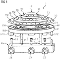
- Fig. 1 illustrates an embodiment of a gas burner 1 according to an exploded view.
- the gas burner 1 comprises an injector holder 2.
- Said injector holder 2 may be adapted to be arranged below a work plate W of a gas hob. In other words, the injector holder 2 may be at least partially integrated in the cooktop.
- the injector holder 2 comprises gas inlets 2.4, 2.5, 2.6 which are fluidly coupled with gas injectors 2.1, 2.2, 2.3.
- the injector holder 2 may comprise multiple end faces.
- the injector holder 2 may comprise a bar or T-like shape and the gas inlets 2.4, 2.5, 2.6 are provided at the free ends or side portions of said injector holder 2.
- the gas injectors 2.1, 2.2, 2.3 may be arranged at an upper side of the injector holder 2 in order to provide an upwardly directed gas flow.
- the gas injectors 2.1, 2.2, 2.3 may be arranged next to each other along a straight line.
- the gas burner 1 comprises a burner crown assembly 3.
- the burner crown assembly 3 may be adapted to be arranged above the injector holder 2.
- the burner crown assembly 3 may comprise multiple parts, namely a burner crown base portion 3.1, and one or more flame spreaders 3.2, 3.2', 3.2".
- Said flame spreaders 3.2, 3.2', 3.2" may be adapted to form flame rings FR1, FR2, FR3.
- the flame spreaders 3.2, 3.2', 3.2" may be formed by separate pieces or a single flame spreader may be provided which comprises multiple flame spreader portions, each flame spreader/flame spreader portion forming a flame ring FR1, FR2, FR3.
- Said one or more flame spreaders 3.2, 3.2', 3.2" are adapted to be arranged on top of the burner crown base portion 3.1.
- the burner crown base portion 3.1 comprises a cup-like shape with a bottom portion and an outer wall portion protruding upwardly for radially confining the gas burner 1.
- said burner crown base portion 3.1 comprises multiple wall portions WP. Said wall portions WP are arranged at a radial inner position with respect to the outer wall portion.
- said wall portions WP may be arranged concentrically with respect to the outer wall portion. Based on said outer wall portion and said wall portions WP multiple chambers CH1, CH2, CH3 are radially confined within the gas burner 1.
- Each one of the one or more flame spreaders 3.2, 3.2', 3.2" or flame spreader portions may be associated with a certain chamber CH1, CH2, CH3.
- said flame spreaders 3.2, 3.2', 3.2" or flame spreader portions may be arranged on top of said burner crown base portion 3.1 in order to confine the chambers CH1, CH2, CH3 in an upward direction.
- Said chambers CH1, CH2, CH3 may be, for example, radial Venturi effect chambers.
- Said chambers CH1, CH2, CH2 may be arranged radially next to each other.
- the first, inner chamber CH1 may be covered by a circular, cup-shaped flame spreader 3.2.
- the outer diameter of said first chamber CH1 may be in the range of 45mm to 55mm, specifically 50mm, 51mm or 52mm.
- the following chambers CH2, CH3 may comprise ring-shaped flame spreaders 3.2', 3.2".
- the outer diameter of the second chamber CH2 may be in the range of 85mm to 100mm, specifically between 90mm and 95mm, particularly 92mm, 93mm or 94mm.
- the outer diameter of the third chamber CH3 may be in the range of 130mm to 145mm, specifically between 135mm and 140mm, particularly 136mm, 137mm or 138mm.
- the height of the chambers may be in the range of 10mm to 15mm, specifically 12mm, 13mm or 14mm, particularly 13.5mm.
- each flame spreader 3.2, 3.2', 3.2" forms a flame ring FR1, FR2, FR3.
- Said flame ring FR1, FR2, FR3 is provided circumferentially at the respective flame spreader 3.2, 3.2', 3.2".
- the flame rings FR1, FR2, FR3 may be arranged in a concentric manner with respect to a vertical middle axis of the gas burner 1, respectively its burner crown assembly 3.
- the flame rings FR1, FR2, FR3 may be constituted by multiple openings or grooves provided at a circumferential slanted side wall of the flame spreaders 3.2, 3.2', 3.2". Said openings or grooves form flame ports of the burner.
- the chambers CH1, CH2, CH3 are separated from each other based on upper-mentioned wall portions and said combustion gas mixture is provided separately to each chamber CH1, CH2, CH3.
- the burner crown assembly 3, specifically the burner crown base portion 3.1 comprises multiple pipes 3.1.1, 3.1.2, 3.1.3 adapted to provide a combustion gas mixture to said chamber CH1, CH2, CH3.
- Each pipe 3.1.1, 3.1.2, 3.1.3 may be associated with a certain chamber CH1, CH2, CH3.
- a first pipe 3.1.1 may be adapted to provide said combustion gas mixture to the first chamber CH1
- a second pipe 3.1.2 may be adapted to provide said combustion gas mixture to the second chamber CH2
- the third pipe 3.1.3 may be adapted to provide said combustion gas mixture to the third chamber CH3.
- Said pipes 3.1.1, 3.1.2, 3.1.3 may be Venturi effect pipes.
- Said pipes 3.1.1, 3.1.2, 3.1.3 may be vertically arranged within the burner crown assembly 3, i.e. the longitudinal axis of the respective pipe 3.1.1, 3.1.2, 3.1.3 is vertically or essentially vertically arranged.
- Said pipes 3.1.1, 3.1.2, 3.1.3 may be, for example, an integral part of said burner crown base portion 3.1.
- the pipes 3.1.1, 3.1.2, 3.1.3 may protrude at the lower side of the burner crown base portion 3.1.
- said burner crown base portion 3.1 may comprise a bottom wall portion at which said pipes 3.1.1, 3.1.2, 3.1.3 protrude downwardly.
- Each pipe 3.1.1, 3.1.2, 3.1.3 may comprise a first free end arranged within the respective chamber CH1, CH2, CH3 and a further free end arranged below the respective chamber CH1, CH2, CH3. Said further free end may be arranged closely above a gas injector 2.1, 2.2, 2.3. Thereby, the each gas injector 2.1, 2.2, 2.3 may be able to provide an upwardly directed steam of gas into said pipe 3.1.1, 3.1.2, 3.1.3 and said pipe 3.1.1, 3.1.2, 3.1.3 guides the gas into the chamber CH1, CH2, CH3 in which its upper free end is located.
- the lower free ends of the pipe 3.1.1, 3.1.2, 3.1.3 may be at least partially open in order to be able to suck primary air. Said primary air is mixed within the respective pipe 3.1.1, 3.1.2, 3.1.3 and the chambers CH1, CH2, CH3 in order to provide a combustion gas mixture at the flame rings FR1, FR2, FR3.
- said pipes 3.1.1, 3.1.2, 3.1.3 are arranged at a distance to each other.
- the pipe 3.1.1 (fluidly connected with the first, inner chamber CH1) may be arranged essentially in the center of the burner crown assembly 3 and the pipes 3.1.2, 3.1.3 may be arranged at opposite sides of said pipe 3.1.1.
- the gas injectors 2.1, 2.2, 2.3 may be arranged at the injection holder 2 such that - in the assembled state of the gas burner 1 - the lower free ends of the pipes 3.1.1, 3.1.2, 3.1.3 are arranged directly above the respective gas injector 2.1, 2.2, 2.3.
- the gas burner 1 provides multiple gas burner stages with different heating power.
- small-sized flame ring FR1 may provide lower heating power than flame ring FR2 and flame ring FR2 may provide lower heating power than flame ring FR3.
- the gas burner 1 may be adapted to be driven according to a three-stage power concept, namely a lower power stage in which only the first flame ring FR1 is active, a medium power stage in which the first and the second flame ring FR1, FR2 is active, and a maximum power level in which all flame rings FR1, FR2, FR3 are active. So, in other words, the flame ring FR1, FR2, FR3 are gradually switched on starting with the inner flame ring when increasing the heating power.
- the heating power may be varied in the range of 0.3KW to 5KW, specifically between (0.5KW to 4KW).
- air gaps AG are provided between adjacent flame rings FR1, FR2, FR3, respectively, flame spreaders 3.2, 3.2', 3.2". More in detail, a first air gap AG may be provided between an inner and a middle flame ring FR1, FR2 and a second air gap AG may be provided between a middle and an outer flame ring FR2, FR3. Said air gap AG may be provided by a space between adjacent chambers CH1, CH2, CH3. Said air gap AG may comprise an annular or essentially annular shape. As shown based on the arrows in Fig.
- the burner crown base portion 3.1 may be arranged at a distance to a bottom hob portion in order to allow an air flow below the bottom wall portion of said burner crown base portion 3.1.
- Said air gaps AG enable a vertically upward-directed air flow between adjacent flame rings FR1, FR2, FR3. Thereby, a further aeration between said flame rings FR1, FR2, FR3 is obtained which improves the combustion. Specifically, said secondary aeration improves combustion.
- the spark plug 5 and the thermocouple 6 may be arranged in the air gap AG between the inner flame ring FR1 and the subsequent flame ring FR2. Thereby the spark plug 5 is able to activate the inner flame ring FR1 and control its state based on the thermocouple 6.
- Fig. 5 to 7 show flame spreaders 3.2, 3.2', 3.2" in closer detail.
- Said middle and outer flame spreaders 3.2', 3.2" may comprise a protrusion 4, protruding downwardly from said flame spreaders 3.2', 3.2".
- the cross section of the chambers CH2, CH3 are reduced because said protrusion 4 extends from said flame spreaders 3.2', 3.2" downwardly into the respective chamber CH2, CH3. So in other words, said protrusion 4 reduces the height h of the chamber CH2, CH3.
- the position of the protrusion 4 may be chosen such that the protrusion 4 is arranged above the free end of the pipe 3.1.2, 3.1.3, through which the combustion gas mixture is provided into said chamber CH2, CH3 (cf. Fig. 7 ). Based on said protrusion 4, the combustion gas mixture is deflected in a circumferential direction and preferably splitted in two combustion gas portions propagating in opposite directions. Thereby, the flame distribution around the respective flame ring FR2, FR3 is balanced.
- the protrusions 4 of the respective flame spreaders 3.2', 3.2" may be provided at opposite sides of the center of the burner crown assembly 3, similar to the chosen position of the pipes 3.1.2, 3.1.3.
- the height h of the protrusion 4 may be chosen such that the height of the chamber CH2, CH3 in the area of the protrusion 4 is in the range between 2mm and 4mm.
- the height of the protrusions 4 may decrease towards its outer ends.
- the length l of the protrusion 4 may be in the range between 10mm and 40mm, specifically between 13mm and 32mm.
- the gas burner may comprise even more than three flame rings, respectively, flame spreaders, e.g. four or five flame rings/ flame spreaders.
Landscapes
- Engineering & Computer Science (AREA)
- Chemical & Material Sciences (AREA)
- Combustion & Propulsion (AREA)
- Mechanical Engineering (AREA)
- General Engineering & Computer Science (AREA)
- Gas Burners (AREA)
- Meat, Egg Or Seafood Products (AREA)
- Baking, Grill, Roasting (AREA)
Abstract
- an injection holder (2) with at least three gas injectors (2.1, 2.2, 2.3);
- a burner crown assembly (3), the burner crown assembly (3) comprising at least three flame rings (FR1, FR2, FR3) with different sizes, the burner crown assembly (3) further comprising at least three chambers (CH1, CH2, CH3) and at least three pipes (3.1.1, 3.1.2, 3.1.3), each pipe (3.1.1, 3.1.2, 3.1.3) being fluidly coupled with a single chamber (CH1, CH2, CH3);
wherein each gas injector (2.1, 2.2, 2.3) is associated with one of said pipes (3.1.1, 3.1.2, 3.1.3) for providing gas into said pipe (3.1.1, 3.1.2, 3.1.3), said pipe (3.1.1, 3.1.2, 3.1.3) being adapted to receive primary air in the area of the injection holder (2) and to provide a combustion mixture of gas and primary air to one of said flame rings (FR1, FR2, FR3) of the burner crown assembly (3). In addition, adjacent flame rings (FR1, FR2, FR3) are separated from each other based on an air gap (AG1, AG2) provided between said adjacent flame rings (FR1, FR2, FR3).
Description
- Generally, the present invention relates to the field of gas burners. More specifically, the present invention relates to a gas burner with multiple flame rings comprising different sizes for providing different heating power levels within a single gas burner.
- Gas burners are well-known in prior art. Specifically, cooking hob gas burners are known which comprise an injection holder and a burner crown assembly. Within said burner crown assembly, a combustion gas chamber is arranged which provides a mixture of gas and primary air to a flame ring comprising a plurality of flame ports.
- Gas hobs are known which comprise multiple separated gas burners of different sizes, specifically, different diameters in order to provide burners with different heating power levels.
- Disadvantageously, current gas hobs are not capable of providing heat at multiple high-power, large-sized burners. So, in case that the gas hob comprises four burners and four pieces of cookware should be heated at high-power burners, gas burners have to be used which do not have the desired power level.
- It is an objective of the embodiments of the present invention to provide a gas burner with improved flexibility in view of the heating power range provided by the gas burner and high effectivity. The objective is solved by the features of the independent claims. Preferred embodiments are given in the dependent claims. If not explicitly indicated otherwise, embodiments of the invention and single features of said embodiments can be freely combined with each other.
- According to an aspect, the invention relates to a gas burner comprising:
- an injection holder with at least three gas injectors; and
- a burner crown assembly, the burner crown assembly comprising at least three flame rings with different sizes, the burner crown assembly further comprising at least three chambers and at least three pipes, each pipe being fluidly coupled with a single chamber.
- Each gas injector is associated with one of said pipes for providing gas into said pipe, said pipe being adapted to receive primary air in the area of the injection holder and to provide a combustion mixture of gas and primary air to one of said flame rings of the burner crown assembly. In addition, adjacent flame rings are separated from each other based on an air gap provided between said adjacent flame rings.
- Said gas burner is advantageous because due to said at least three different-sized flame rings said gas burner can provide a small heating power by only powering the smallest flame ring or a higher heating power by powering two or more of said flame rings. Based on said air gaps, secondary aeration is provided which increases the effectivity of the combustion process.
- According to embodiments, said air gap comprises an annular shape and is concentrically arranged with respect to said flame rings. So, in other words, an annular flame ring is radially surrounded by said air gap. The radial width of the air gap may be in the range of 4mm to 10 mm, particularly 6mm to 8mm. Thereby, the combustion process of the adjacent flame ring is significantly improved.
- According to embodiments, said burner crown assembly enables an air flow below an outer chamber in order to provide air to said air gaps. So, in other words, air is sucked below the bottom wall portion of the burner crown assembly and preferably above the workplate and flows subsequently upwardly through said air gap.
- According to embodiments, said burner crown assembly comprises a burner crown base portion on which at least one flame spreader building said flame rings is based on. Said burner crown base portion may comprise multiple subdivisions for forming lower boundaries for said chambers. The burner crown base portion may be integrally formed, i.e. said burner crown may be a single-piece element. The subdivisions forming said chambers may be linked by bars / webs, said bars / webs bridging the air gaps between said chambers. The burner crown base portion may also comprise said pipes.
- According to embodiments, said burner crown base portion comprises wall portions for separating said chambers from said air gaps. Said wall portions may be side wall portions in order to laterally confine the chambers. Said wall portions may protrude upwardly from a bottom wall portion of said burner crown base portion.
- According to embodiments, said wall portions are concentrically arranged in order to from concentric annular chambers. An inner chamber may be surrounded by an air gap, followed by a further chamber which surrounds said air gap. Similarly, said further chamber may be surrounded by a further air gap, said further air gap itself being surrounded by an outer chamber. Thereby a burner structure is obtained which ensures high efficiency of the gas burner.
- According to embodiments, said pipes protrude downwardly from said burner crown base portion. Thereby, gas provided by a gas injector and ambient air can be received at a level below the bottom wall portion of the burner crown base portion.
- According to embodiments, said flame rings are formed by one or more flame spreaders, wherein a flame spreader or a flame spreader portion comprises a protrusion protruding into the chamber in order to reduce the height of the chamber based on said protrusion. Said protrusion may be an arc-shaped protrusion. Based on said protrusion, the gas mixture distribution within the chamber can be balanced.
- According to embodiments, said protrusion is located at a position within the chamber at which said pipe providing said combustion mixture of gas and primary air into said chamber is arranged. Thereby, the combustion mixture of gas and primary air is deflected at said protrusion and splitted in two gas flow portions propagating in opposite directions.
- According to embodiments, the chambers are separated from each other with respect to the provision of a combustion mixture of gas and primary air into the respective chamber. So, the combustion gas mixture provided to a certain chamber is not able to flow into another chamber provided radial inwardly or outwardly. Thereby, said combustion gas mixture can be provided to each flame ring separately.
- According to embodiments, each gas injector is coupled with a separate gas inlet. The gas inlet may be, for example, provided at the injection holder. Thereby it is possible to control the provision of gas separately to each chamber, respectively to each flame ring.
- According to embodiments, the burner crown assembly is arranged above the injection holder. So, gas provided by the gas injectors arranged at the injection holder can flow upwardly into the respective chamber in order to be guided by said chamber towards the flame ports of the flame ring which are circumferentially arranged at the respective burner crown.
- According to embodiments, the pipes are arranged at a lateral distance to each other. Thereby it is possible to arrange separate gas injectors below the free end of the pipes in order to provide selectively gas into said pipes.
- According to embodiments, the pipes are arranged next to each other in a straight line. Said arrangement is advantageous because the provision of gas to said pipes is simplified. The arrangement of the gas injectors may be chosen similarly in order to enable a technically simple provision of gas to said pipes.
- According to embodiments, the pipe of the inner burner crown is arranged in the centre of the burner crown assembly. Said configuration is advantageous because the inner burner crown comprises the smallest cross-sectional area and due to the centred arrangement of the pipe, the construction of the burner crown assembly is simplified and a homogenous flame formation at the first flame ring is obtained.
- According to embodiments, the longitudinal axes of the pipes are vertically arranged. Thereby, the gas guided within the pipe can flow upwardly through the pipe thereby being mixed with the primary air sucked at the bottom of the pipe.
- According to embodiments, the inner chamber is covered by a cup-shaped flame spreader. Said inner chamber may be a circular chamber and the cup-shaped flame spreader may close said circular chamber at the upper side. The further flame spreaders may be ring-shaped flame spreaders.
- According to embodiments, each pipe comprises at its bottom an open free end. Said open free end provides an air inlet at which primary air is sucked in in order to be mixed with the gas provided by the gas injector. Said air inlet may be provided below a workplate of the gas burner.
- According to embodiments, a spark plug and/or a thermocouple is provided in an air gap between the inner flame ring and a further flame ring adjacent to said inner flame ring. Thereby the ignition behaviour and operational safety is significantly improved.
- According to a further aspect, the invention refers to a gas hob with a gas burner configured according to anyone of the preceding embodiments.
- The terms "essentially", "substantially" or "approximately" as used in the invention means deviations from the exact value by +/- 10%, preferably by +/- 5% and/or deviations in the form of changes that are insignificant for the function.
- The various aspects of the invention, including its particular features and advantages, will be readily understood from the following detailed description and the accompanying drawings, in which:
- Fig. 1
- shows an example exploded perspective view of the gas burner according to an embodiment;
- Fig. 2
- shows an example top view of the gas burner according to
Fig. 1 ; - Fig. 3
- shows a lateral sectional side view of a gas burner according to
Fig. 1 and2 ; - Fig. 4
- illustrates a secondary aeration effect caused by air gaps provided between adjacent flame rings;
- Fig. 5
- shows a lower perspective view of a flame spreader assembly with protrusions at the bottom side;
- Fig. 6
- shows a section of a ring-shaped flame spreader with an arc-shaped protrusion;
- Fig. 7
- shows a sectional view of a pipe and a flame spreader comprising a protrusion at a bottom side, said protrusion projecting into a chamber confined between the burner crown base portion and the flame spreader.
- The present invention will now be described more fully with reference to the accompanying drawings, in which example embodiments are shown. However, this invention should not be construed as limited to the embodiments set forth herein. Throughout the following description similar reference numerals have been used to denote similar elements, parts, items or features, when applicable.
-
Fig. 1 illustrates an embodiment of a gas burner 1 according to an exploded view. The gas burner 1 comprises aninjector holder 2. Saidinjector holder 2 may be adapted to be arranged below a work plate W of a gas hob. In other words, theinjector holder 2 may be at least partially integrated in the cooktop. Theinjector holder 2 comprises gas inlets 2.4, 2.5, 2.6 which are fluidly coupled with gas injectors 2.1, 2.2, 2.3. - According to an embodiment, the
injector holder 2 may comprise multiple end faces. For example, theinjector holder 2 may comprise a bar or T-like shape and the gas inlets 2.4, 2.5, 2.6 are provided at the free ends or side portions of saidinjector holder 2. The gas injectors 2.1, 2.2, 2.3 may be arranged at an upper side of theinjector holder 2 in order to provide an upwardly directed gas flow. For example, the gas injectors 2.1, 2.2, 2.3 may be arranged next to each other along a straight line. - In addition, the gas burner 1 comprises a burner crown assembly 3. The burner crown assembly 3 may be adapted to be arranged above the
injector holder 2. The burner crown assembly 3 may comprise multiple parts, namely a burner crown base portion 3.1, and one or more flame spreaders 3.2, 3.2', 3.2". Said flame spreaders 3.2, 3.2', 3.2" may be adapted to form flame rings FR1, FR2, FR3. The flame spreaders 3.2, 3.2', 3.2" may be formed by separate pieces or a single flame spreader may be provided which comprises multiple flame spreader portions, each flame spreader/flame spreader portion forming a flame ring FR1, FR2, FR3. Said one or more flame spreaders 3.2, 3.2', 3.2" are adapted to be arranged on top of the burner crown base portion 3.1. - More in detail, the burner crown base portion 3.1 comprises a cup-like shape with a bottom portion and an outer wall portion protruding upwardly for radially confining the gas burner 1. In addition, said burner crown base portion 3.1 comprises multiple wall portions WP. Said wall portions WP are arranged at a radial inner position with respect to the outer wall portion. In addition, said wall portions WP may be arranged concentrically with respect to the outer wall portion. Based on said outer wall portion and said wall portions WP multiple chambers CH1, CH2, CH3 are radially confined within the gas burner 1. Each one of the one or more flame spreaders 3.2, 3.2', 3.2" or flame spreader portions may be associated with a certain chamber CH1, CH2, CH3. More in detail, said flame spreaders 3.2, 3.2', 3.2" or flame spreader portions may be arranged on top of said burner crown base portion 3.1 in order to confine the chambers CH1, CH2, CH3 in an upward direction. Said chambers CH1, CH2, CH3 may be, for example, radial Venturi effect chambers. Said chambers CH1, CH2, CH2 may be arranged radially next to each other.
- The first, inner chamber CH1 may be covered by a circular, cup-shaped flame spreader 3.2. The outer diameter of said first chamber CH1 may be in the range of 45mm to 55mm, specifically 50mm, 51mm or 52mm. The following chambers CH2, CH3 may comprise ring-shaped flame spreaders 3.2', 3.2". The outer diameter of the second chamber CH2 may be in the range of 85mm to 100mm, specifically between 90mm and 95mm, particularly 92mm, 93mm or 94mm. The outer diameter of the third chamber CH3 may be in the range of 130mm to 145mm, specifically between 135mm and 140mm, particularly 136mm, 137mm or 138mm. The height of the chambers may be in the range of 10mm to 15mm, specifically 12mm, 13mm or 14mm, particularly 13.5mm.
- In order to provide a combustion gas mixture, each flame spreader 3.2, 3.2', 3.2" forms a flame ring FR1, FR2, FR3. Said flame ring FR1, FR2, FR3 is provided circumferentially at the respective flame spreader 3.2, 3.2', 3.2". As shown in
Fig. 2 , the flame rings FR1, FR2, FR3 may be arranged in a concentric manner with respect to a vertical middle axis of the gas burner 1, respectively its burner crown assembly 3. The flame rings FR1, FR2, FR3 may be constituted by multiple openings or grooves provided at a circumferential slanted side wall of the flame spreaders 3.2, 3.2', 3.2". Said openings or grooves form flame ports of the burner. - In order to be able to selectively provide a combustion gas mixture in a certain chamber CH1, CH2, CH3, the chambers CH1, CH2, CH3 are separated from each other based on upper-mentioned wall portions and said combustion gas mixture is provided separately to each chamber CH1, CH2, CH3. More in detail, the burner crown assembly 3, specifically the burner crown base portion 3.1 comprises multiple pipes 3.1.1, 3.1.2, 3.1.3 adapted to provide a combustion gas mixture to said chamber CH1, CH2, CH3. Each pipe 3.1.1, 3.1.2, 3.1.3 may be associated with a certain chamber CH1, CH2, CH3. For example, a first pipe 3.1.1 may be adapted to provide said combustion gas mixture to the first chamber CH1, a second pipe 3.1.2 may be adapted to provide said combustion gas mixture to the second chamber CH2 and the third pipe 3.1.3 may be adapted to provide said combustion gas mixture to the third chamber CH3. Said pipes 3.1.1, 3.1.2, 3.1.3 may be Venturi effect pipes.
- Said pipes 3.1.1, 3.1.2, 3.1.3 may be vertically arranged within the burner crown assembly 3, i.e. the longitudinal axis of the respective pipe 3.1.1, 3.1.2, 3.1.3 is vertically or essentially vertically arranged. Said pipes 3.1.1, 3.1.2, 3.1.3 may be, for example, an integral part of said burner crown base portion 3.1. The pipes 3.1.1, 3.1.2, 3.1.3 may protrude at the lower side of the burner crown base portion 3.1. Specifically, said burner crown base portion 3.1 may comprise a bottom wall portion at which said pipes 3.1.1, 3.1.2, 3.1.3 protrude downwardly. Each pipe 3.1.1, 3.1.2, 3.1.3 may comprise a first free end arranged within the respective chamber CH1, CH2, CH3 and a further free end arranged below the respective chamber CH1, CH2, CH3. Said further free end may be arranged closely above a gas injector 2.1, 2.2, 2.3. Thereby, the each gas injector 2.1, 2.2, 2.3 may be able to provide an upwardly directed steam of gas into said pipe 3.1.1, 3.1.2, 3.1.3 and said pipe 3.1.1, 3.1.2, 3.1.3 guides the gas into the chamber CH1, CH2, CH3 in which its upper free end is located.
- The lower free ends of the pipe 3.1.1, 3.1.2, 3.1.3 may be at least partially open in order to be able to suck primary air. Said primary air is mixed within the respective pipe 3.1.1, 3.1.2, 3.1.3 and the chambers CH1, CH2, CH3 in order to provide a combustion gas mixture at the flame rings FR1, FR2, FR3.
- As shown in
Fig 1 , said pipes 3.1.1, 3.1.2, 3.1.3 are arranged at a distance to each other. The pipe 3.1.1 (fluidly connected with the first, inner chamber CH1) may be arranged essentially in the center of the burner crown assembly 3 and the pipes 3.1.2, 3.1.3 may be arranged at opposite sides of said pipe 3.1.1. The gas injectors 2.1, 2.2, 2.3 may be arranged at theinjection holder 2 such that - in the assembled state of the gas burner 1 - the lower free ends of the pipes 3.1.1, 3.1.2, 3.1.3 are arranged directly above the respective gas injector 2.1, 2.2, 2.3. - Due to the different size of the flame rings FR1, FR2, FR3, respectively the flame spreaders 3.2, 3.2', 3.2", the gas burner 1 provides multiple gas burner stages with different heating power. For example, small-sized flame ring FR1 may provide lower heating power than flame ring FR2 and flame ring FR2 may provide lower heating power than flame ring FR3.
- The gas burner 1 may be adapted to be driven according to a three-stage power concept, namely a lower power stage in which only the first flame ring FR1 is active, a medium power stage in which the first and the second flame ring FR1, FR2 is active, and a maximum power level in which all flame rings FR1, FR2, FR3 are active. So, in other words, the flame ring FR1, FR2, FR3 are gradually switched on starting with the inner flame ring when increasing the heating power. The heating power may be varied in the range of 0.3KW to 5KW, specifically between (0.5KW to 4KW).
- As shown in
Fig. 2 to 4 , air gaps AG are provided between adjacent flame rings FR1, FR2, FR3, respectively, flame spreaders 3.2, 3.2', 3.2". More in detail, a first air gap AG may be provided between an inner and a middle flame ring FR1, FR2 and a second air gap AG may be provided between a middle and an outer flame ring FR2, FR3. Said air gap AG may be provided by a space between adjacent chambers CH1, CH2, CH3. Said air gap AG may comprise an annular or essentially annular shape. As shown based on the arrows inFig. 4 , the burner crown base portion 3.1 may be arranged at a distance to a bottom hob portion in order to allow an air flow below the bottom wall portion of said burner crown base portion 3.1. Said air gaps AG enable a vertically upward-directed air flow between adjacent flame rings FR1, FR2, FR3. Thereby, a further aeration between said flame rings FR1, FR2, FR3 is obtained which improves the combustion. Specifically, said secondary aeration improves combustion. - The
spark plug 5 and thethermocouple 6 may be arranged in the air gap AG between the inner flame ring FR1 and the subsequent flame ring FR2. Thereby thespark plug 5 is able to activate the inner flame ring FR1 and control its state based on thethermocouple 6. -
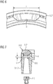
Fig. 5 to 7 show flame spreaders 3.2, 3.2', 3.2" in closer detail. Said middle and outer flame spreaders 3.2', 3.2" may comprise aprotrusion 4, protruding downwardly from said flame spreaders 3.2', 3.2". Based on saidprotrusion 4, the cross section of the chambers CH2, CH3 are reduced because saidprotrusion 4 extends from said flame spreaders 3.2', 3.2" downwardly into the respective chamber CH2, CH3. So in other words, saidprotrusion 4 reduces the height h of the chamber CH2, CH3. - The position of the
protrusion 4 may be chosen such that theprotrusion 4 is arranged above the free end of the pipe 3.1.2, 3.1.3, through which the combustion gas mixture is provided into said chamber CH2, CH3 (cf.Fig. 7 ). Based on saidprotrusion 4, the combustion gas mixture is deflected in a circumferential direction and preferably splitted in two combustion gas portions propagating in opposite directions. Thereby, the flame distribution around the respective flame ring FR2, FR3 is balanced. Theprotrusions 4 of the respective flame spreaders 3.2', 3.2" may be provided at opposite sides of the center of the burner crown assembly 3, similar to the chosen position of the pipes 3.1.2, 3.1.3. - The height h of the
protrusion 4 may be chosen such that the height of the chamber CH2, CH3 in the area of theprotrusion 4 is in the range between 2mm and 4mm. The height of theprotrusions 4 may decrease towards its outer ends. The length l of theprotrusion 4 may be in the range between 10mm and 40mm, specifically between 13mm and 32mm. - In the disclosure before, an embodiment with three flame rings, respectively, flame spreaders have been described. It is worth mentioning that the gas burner may comprise even more than three flame rings, respectively, flame spreaders, e.g. four or five flame rings/ flame spreaders.
- It should be noted that the description and drawings merely illustrate the principles of the proposed gas burner. Those skilled in the art will be able to implement various arrangements that, although not explicitly described or shown herein, embody the principles of the invention.
-
- 1
- gas burner
- 2
- injection holder
- 2a
- injection holder portion
- 2b
- injection holder portion
- 2.1, 2.2, 2.3
- gas injector
- 2.4, 2.5, 2.6
- gas inlet
- 3
- burner crown assembly
- 3.1
- burner crown base portion
- 3.1.1
- pipe
- 3.1.2
- pipe
- 3.1.3
- pipe
- 3.2
- flame spreader
- 3.2'
- flame spreader
- 3.2"
- flame spreader
- 4
- protrusion
- 5
- spark plug
- 6
- thermocouple
- AG
- air gap
- CH1
- first chamber
- CH2
- second chamber
- CH3
- third chamber
- FR1
- first flame ring
- FR2
- second flame ring
- FR3
- third flame ring
- l
- length
- h
- height
- W
- workplate
- WP
- wall portion
Claims (15)
- Gas burner comprising:- an injection holder (2) with at least three gas injectors (2.1, 2.2, 2.3);- a burner crown assembly (3), the burner crown assembly (3) comprising at least three flame rings (FR1, FR2, FR3) with different sizes, the burner crown assembly (3) further comprising at least three chambers (CH1, CH2, CH3) and at least three pipes (3.1.1, 3.1.2, 3.1.3), each pipe (3.1.1, 3.1.2, 3.1.3) being fluidly coupled with a single chamber (CH1, CH2, CH3);wherein each gas injector (2.1, 2.2, 2.3) is associated with one of said pipes (3.1.1, 3.1.2, 3.1.3) for providing gas into said pipe (3.1.1, 3.1.2, 3.1.3), said pipe (3.1.1, 3.1.2, 3.1.3) being adapted to receive primary air in the area of the injection holder (2) and to provide a combustion mixture of gas and primary air to one of said flame rings (FR1, FR2, FR3) of the burner crown assembly (3), wherein adjacent flame rings (FR1, FR2, FR3) are separated from each other based on an air gap (AG1, AG2) provided between said adjacent flame rings (FR1, FR2, FR3).
- Gas burner according to claim 1, wherein said air gap (AG1, AG2) comprises an annular shape and is concentrically arranged with respect to said flame rings (FR1, FR2, FR3).
- Gas burner according to anyone of the preceding claims, wherein said burner crown assembly (3) enables an air flow below an outer chamber (CH2, CH3) in order to provide air to said air gaps (AG1, AG2).
- Gas burner according to anyone of the preceding claims, wherein said burner crown assembly (3) comprises a burner crown base portion (3.1) on which at least one flame spreader (3.2, 3.2', 3.2") building said flame rings (FR1, FR2, FR3) is based on.
- Gas burner according to claim 4, wherein said burner crown base (3.1) portion comprises wall portions (WP) for separating said chambers (CH1, CH2, CH3) from said air gaps (AG1, AG2).
- Gas burner according to claim 5, wherein said wall portions (WP) are concentrically arranged in order to from concentric annular chambers (CH1, CH2, CH3).
- Gas burner according to anyone of the preceding claims, wherein said pipes (3.1.1, 3.1.2, 3.1.3) protrude downwardly from said burner crown base portion (3.1).
- Gas burner according to anyone of the preceding claims, wherein said flame rings (FR1, FR2, FR3) are formed by one or more flame spreaders (3.2, 3.2', 3.2"), wherein a flame spreader (3.2, 3.2', 3.2") or a flame spreader portion comprises a protrusion (4) protruding into the chamber (CH2, CH3) in order to reduce the height of the chamber (CH2, CH3) based on said protrusion (4).
- Gas burner according to claim 8, wherein said protrusion (4) is located at a position within the chamber (CH2, CH3) at which said pipe (3.1.2, 3.1.3) providing said combustion mixture of gas and primary air into said chamber (CH2, CH3) is arranged.
- Gas burner according to anyone of the preceding claims, wherein each gas injector (2.1, 2.2, 2.3) is coupled with a separate gas inlet (2.4, 2.5, 2.6).
- Gas burner according to anyone of the preceding claims, wherein the burner crown assembly (3) is arranged above the injection holder (2).
- Gas burner according to anyone of the preceding claims, wherein the pipes (3.1.1, 3.1.2, 3.1.3) are arranged at a lateral distance to each other, specifically, the pipes (3.1.1, 3.1.2, 3.1.3) are arranged next to each other in a straight line.
- Gas burner according to anyone of the preceding claims, wherein the longitudinal axes of the pipes (3.1.1, 3.1.2, 3.1.3) are vertically arranged and/or each pipe (3.1.1, 3.1.2, 3.1.3) comprise at its bottom an open free end.
- Gas burner according to anyone of the preceding claims, wherein a spark plug (5) and/or a thermocouple (6) is provided in an air gap (AG2) between the inner flame ring (FR1) and a further flame ring (FR2) adjacent to said inner flame ring (FR1).
- Cooking hob comprising a gas burner (1) configured according to anyone of the preceding claims.
Priority Applications (7)
| Application Number | Priority Date | Filing Date | Title |
|---|---|---|---|
| EP17180169.9A EP3425276B1 (en) | 2017-07-07 | 2017-07-07 | Cooking hob comprising a gas burner |
| ES17180169T ES2924491T3 (en) | 2017-07-07 | 2017-07-07 | Cooktop with a gas burner |
| BR112020000160-0A BR112020000160B1 (en) | 2017-07-07 | 2018-06-25 | COOKING STOVE COMPRISING A GAS BURNER |
| CN201880044608.0A CN110869672A (en) | 2017-07-07 | 2018-06-25 | Gas burners and cooktops including gas burners |
| PCT/EP2018/066956 WO2019007739A1 (en) | 2017-07-07 | 2018-06-25 | Gas burner and hob comprising a gas burner |
| US16/626,611 US11268700B2 (en) | 2017-07-07 | 2018-06-25 | Gas burner and hob comprising a gas burner |
| AU2018296711A AU2018296711B2 (en) | 2017-07-07 | 2018-06-25 | Gas burner and hob comprising a gas burner |
Applications Claiming Priority (1)
| Application Number | Priority Date | Filing Date | Title |
|---|---|---|---|
| EP17180169.9A EP3425276B1 (en) | 2017-07-07 | 2017-07-07 | Cooking hob comprising a gas burner |
Publications (2)
| Publication Number | Publication Date |
|---|---|
| EP3425276A1 true EP3425276A1 (en) | 2019-01-09 |
| EP3425276B1 EP3425276B1 (en) | 2022-06-01 |
Family
ID=59298336
Family Applications (1)
| Application Number | Title | Priority Date | Filing Date |
|---|---|---|---|
| EP17180169.9A Active EP3425276B1 (en) | 2017-07-07 | 2017-07-07 | Cooking hob comprising a gas burner |
Country Status (6)
| Country | Link |
|---|---|
| US (1) | US11268700B2 (en) |
| EP (1) | EP3425276B1 (en) |
| CN (1) | CN110869672A (en) |
| AU (1) | AU2018296711B2 (en) |
| ES (1) | ES2924491T3 (en) |
| WO (1) | WO2019007739A1 (en) |
Families Citing this family (2)
| Publication number | Priority date | Publication date | Assignee | Title |
|---|---|---|---|---|
| CN111964101B (en) * | 2020-08-27 | 2022-03-15 | 长沙理工大学 | Kitchen waste oil auxiliary combustion type gas stove |
| CN115899692A (en) * | 2021-09-30 | 2023-04-04 | 佛山市顺德区美的洗涤电器制造有限公司 | Fire cover and burner with same |
Citations (8)
| Publication number | Priority date | Publication date | Assignee | Title |
|---|---|---|---|---|
| FR715717A (en) * | 1931-04-20 | 1931-12-08 | Fr De Chaleur Et Lumiere Soc | Gas burner |
| FR749529A (en) * | 1933-01-25 | 1933-07-25 | Ring gas burner | |
| FR1220131A (en) * | 1958-12-31 | 1960-05-23 | Procedes Sauter | Multiple venturis burner |
| US6132205A (en) * | 2000-01-06 | 2000-10-17 | Harneit; Uwe | Multi-ring sealed gas burner |
| US20100206293A1 (en) * | 2009-02-18 | 2010-08-19 | Electrolux Home Products, Inc. | Gas burner |
| EP2618054A2 (en) * | 2012-01-18 | 2013-07-24 | ISPHORDING Germany GmbH | Gas burner with at least three flame circles |
| WO2014082755A1 (en) * | 2012-11-30 | 2014-06-05 | German Gabtec Gmbh | Controlling the gas supply of a gas burner |
| WO2014191825A1 (en) * | 2013-05-29 | 2014-12-04 | Defendi Italy S.R.L. | Improved gas burner |
Family Cites Families (6)
| Publication number | Priority date | Publication date | Assignee | Title |
|---|---|---|---|---|
| CN2823848Y (en) | 2005-06-15 | 2006-10-04 | 谭六明 | Face air inlet type range burner |
| CN101089468A (en) * | 2007-05-25 | 2007-12-19 | 江苏光芒燃具股份有限公司 | High energy, whole oxygen supply, three-gas compatible burner |
| US20100279238A1 (en) * | 2009-05-02 | 2010-11-04 | Uwe Harneit | Gas burner |
| CN201606877U (en) | 2010-01-15 | 2010-10-13 | 廖珈 | Novel burner |
| CA2934675A1 (en) * | 2015-07-02 | 2017-01-02 | Mabe, S.A. De C.V. | Multi burner ovni |
| CN205279084U (en) | 2015-11-18 | 2016-06-01 | 广东星立方厨房科技有限公司 | A kind of updraft type cooker burner |
-
2017
- 2017-07-07 EP EP17180169.9A patent/EP3425276B1/en active Active
- 2017-07-07 ES ES17180169T patent/ES2924491T3/en active Active
-
2018
- 2018-06-25 US US16/626,611 patent/US11268700B2/en active Active
- 2018-06-25 AU AU2018296711A patent/AU2018296711B2/en active Active
- 2018-06-25 WO PCT/EP2018/066956 patent/WO2019007739A1/en not_active Ceased
- 2018-06-25 CN CN201880044608.0A patent/CN110869672A/en active Pending
Patent Citations (8)
| Publication number | Priority date | Publication date | Assignee | Title |
|---|---|---|---|---|
| FR715717A (en) * | 1931-04-20 | 1931-12-08 | Fr De Chaleur Et Lumiere Soc | Gas burner |
| FR749529A (en) * | 1933-01-25 | 1933-07-25 | Ring gas burner | |
| FR1220131A (en) * | 1958-12-31 | 1960-05-23 | Procedes Sauter | Multiple venturis burner |
| US6132205A (en) * | 2000-01-06 | 2000-10-17 | Harneit; Uwe | Multi-ring sealed gas burner |
| US20100206293A1 (en) * | 2009-02-18 | 2010-08-19 | Electrolux Home Products, Inc. | Gas burner |
| EP2618054A2 (en) * | 2012-01-18 | 2013-07-24 | ISPHORDING Germany GmbH | Gas burner with at least three flame circles |
| WO2014082755A1 (en) * | 2012-11-30 | 2014-06-05 | German Gabtec Gmbh | Controlling the gas supply of a gas burner |
| WO2014191825A1 (en) * | 2013-05-29 | 2014-12-04 | Defendi Italy S.R.L. | Improved gas burner |
Also Published As
| Publication number | Publication date |
|---|---|
| WO2019007739A1 (en) | 2019-01-10 |
| US20200124288A1 (en) | 2020-04-23 |
| EP3425276B1 (en) | 2022-06-01 |
| CN110869672A (en) | 2020-03-06 |
| AU2018296711B2 (en) | 2023-11-02 |
| AU2018296711A1 (en) | 2019-12-05 |
| US11268700B2 (en) | 2022-03-08 |
| BR112020000160A2 (en) | 2020-07-14 |
| ES2924491T3 (en) | 2022-10-07 |
Similar Documents
| Publication | Publication Date | Title |
|---|---|---|
| EP3339731B1 (en) | Gas burner and hob comprising a gas burner | |
| US6332460B1 (en) | Gas burner particularly for incorporated cooking hobs of a gas cooker | |
| US8899972B2 (en) | Burner designed for wide range of input rates | |
| EP2258982B1 (en) | Improved gas burner | |
| EP2835580A2 (en) | Inner swirling flame gas burner | |
| US9416963B2 (en) | Cooking top with improved gas top burner | |
| AU2018296711B2 (en) | Gas burner and hob comprising a gas burner | |
| EP3263986A1 (en) | High efficiency high power inner flame burner | |
| WO2016145746A1 (en) | Burner and gas appliance | |
| EP3343104B1 (en) | Distributed vertical flame burner | |
| EP0797048A1 (en) | Gas burner for kitchen appliances | |
| CN104713085A (en) | Burner and gas appliance | |
| EP3173697B1 (en) | Gas burner and hob comprising a gas burner | |
| EP3054222B1 (en) | A gas burner assembly | |
| CN109416174B (en) | Gas Burners and Home Cooking Appliances | |
| EP3591289B1 (en) | A dual circuit burner, a gas burner arrangement and a gas stove | |
| CN109724082B (en) | High-efficiency burner | |
| CN204534581U (en) | Burner and gas appliance | |
| CN113330253A (en) | Pot support for a gas cooker, gas cooker and method for producing a pot support | |
| KR20200041539A (en) | High firepower gas burner | |
| BR112020000160B1 (en) | COOKING STOVE COMPRISING A GAS BURNER | |
| CN222911652U (en) | Flame cap assemblies, burners and gas stoves | |
| JP2015102268A (en) | Gas cooking stove | |
| EP3748230B1 (en) | Gas burner assembly | |
| CN216010845U (en) | Fire cover and combustor with same |
Legal Events
| Date | Code | Title | Description |
|---|---|---|---|
| PUAI | Public reference made under article 153(3) epc to a published international application that has entered the european phase |
Free format text: ORIGINAL CODE: 0009012 |
|
| STAA | Information on the status of an ep patent application or granted ep patent |
Free format text: STATUS: THE APPLICATION HAS BEEN PUBLISHED |
|
| AK | Designated contracting states |
Kind code of ref document: A1 Designated state(s): AL AT BE BG CH CY CZ DE DK EE ES FI FR GB GR HR HU IE IS IT LI LT LU LV MC MK MT NL NO PL PT RO RS SE SI SK SM TR |
|
| AX | Request for extension of the european patent |
Extension state: BA ME |
|
| STAA | Information on the status of an ep patent application or granted ep patent |
Free format text: STATUS: REQUEST FOR EXAMINATION WAS MADE |
|
| 17P | Request for examination filed |
Effective date: 20190709 |
|
| RBV | Designated contracting states (corrected) |
Designated state(s): AL AT BE BG CH CY CZ DE DK EE ES FI FR GB GR HR HU IE IS IT LI LT LU LV MC MK MT NL NO PL PT RO RS SE SI SK SM TR |
|
| STAA | Information on the status of an ep patent application or granted ep patent |
Free format text: STATUS: EXAMINATION IS IN PROGRESS |
|
| 17Q | First examination report despatched |
Effective date: 20200728 |
|
| GRAP | Despatch of communication of intention to grant a patent |
Free format text: ORIGINAL CODE: EPIDOSNIGR1 |
|
| STAA | Information on the status of an ep patent application or granted ep patent |
Free format text: STATUS: GRANT OF PATENT IS INTENDED |
|
| INTG | Intention to grant announced |
Effective date: 20210722 |
|
| GRAJ | Information related to disapproval of communication of intention to grant by the applicant or resumption of examination proceedings by the epo deleted |
Free format text: ORIGINAL CODE: EPIDOSDIGR1 |
|
| STAA | Information on the status of an ep patent application or granted ep patent |
Free format text: STATUS: EXAMINATION IS IN PROGRESS |
|
| INTC | Intention to grant announced (deleted) | ||
| GRAP | Despatch of communication of intention to grant a patent |
Free format text: ORIGINAL CODE: EPIDOSNIGR1 |
|
| STAA | Information on the status of an ep patent application or granted ep patent |
Free format text: STATUS: GRANT OF PATENT IS INTENDED |
|
| INTG | Intention to grant announced |
Effective date: 20220105 |
|
| GRAS | Grant fee paid |
Free format text: ORIGINAL CODE: EPIDOSNIGR3 |
|
| GRAA | (expected) grant |
Free format text: ORIGINAL CODE: 0009210 |
|
| STAA | Information on the status of an ep patent application or granted ep patent |
Free format text: STATUS: THE PATENT HAS BEEN GRANTED |
|
| AK | Designated contracting states |
Kind code of ref document: B1 Designated state(s): AL AT BE BG CH CY CZ DE DK EE ES FI FR GB GR HR HU IE IS IT LI LT LU LV MC MK MT NL NO PL PT RO RS SE SI SK SM TR |
|
| REG | Reference to a national code |
Ref country code: GB Ref legal event code: FG4D |
|
| REG | Reference to a national code |
Ref country code: AT Ref legal event code: REF Ref document number: 1495606 Country of ref document: AT Kind code of ref document: T Effective date: 20220615 Ref country code: CH Ref legal event code: EP |
|
| REG | Reference to a national code |
Ref country code: IE Ref legal event code: FG4D |
|
| REG | Reference to a national code |
Ref country code: DE Ref legal event code: R096 Ref document number: 602017057942 Country of ref document: DE |
|
| REG | Reference to a national code |
Ref country code: LT Ref legal event code: MG9D |
|
| REG | Reference to a national code |
Ref country code: NL Ref legal event code: MP Effective date: 20220601 |
|
| REG | Reference to a national code |
Ref country code: ES Ref legal event code: FG2A Ref document number: 2924491 Country of ref document: ES Kind code of ref document: T3 Effective date: 20221007 |
|
| PG25 | Lapsed in a contracting state [announced via postgrant information from national office to epo] |
Ref country code: SE Free format text: LAPSE BECAUSE OF FAILURE TO SUBMIT A TRANSLATION OF THE DESCRIPTION OR TO PAY THE FEE WITHIN THE PRESCRIBED TIME-LIMIT Effective date: 20220601 Ref country code: NO Free format text: LAPSE BECAUSE OF FAILURE TO SUBMIT A TRANSLATION OF THE DESCRIPTION OR TO PAY THE FEE WITHIN THE PRESCRIBED TIME-LIMIT Effective date: 20220901 Ref country code: LT Free format text: LAPSE BECAUSE OF FAILURE TO SUBMIT A TRANSLATION OF THE DESCRIPTION OR TO PAY THE FEE WITHIN THE PRESCRIBED TIME-LIMIT Effective date: 20220601 Ref country code: HR Free format text: LAPSE BECAUSE OF FAILURE TO SUBMIT A TRANSLATION OF THE DESCRIPTION OR TO PAY THE FEE WITHIN THE PRESCRIBED TIME-LIMIT Effective date: 20220601 Ref country code: GR Free format text: LAPSE BECAUSE OF FAILURE TO SUBMIT A TRANSLATION OF THE DESCRIPTION OR TO PAY THE FEE WITHIN THE PRESCRIBED TIME-LIMIT Effective date: 20220902 Ref country code: FI Free format text: LAPSE BECAUSE OF FAILURE TO SUBMIT A TRANSLATION OF THE DESCRIPTION OR TO PAY THE FEE WITHIN THE PRESCRIBED TIME-LIMIT Effective date: 20220601 Ref country code: BG Free format text: LAPSE BECAUSE OF FAILURE TO SUBMIT A TRANSLATION OF THE DESCRIPTION OR TO PAY THE FEE WITHIN THE PRESCRIBED TIME-LIMIT Effective date: 20220901 |
|
| REG | Reference to a national code |
Ref country code: AT Ref legal event code: MK05 Ref document number: 1495606 Country of ref document: AT Kind code of ref document: T Effective date: 20220601 |
|
| PG25 | Lapsed in a contracting state [announced via postgrant information from national office to epo] |
Ref country code: RS Free format text: LAPSE BECAUSE OF FAILURE TO SUBMIT A TRANSLATION OF THE DESCRIPTION OR TO PAY THE FEE WITHIN THE PRESCRIBED TIME-LIMIT Effective date: 20220601 Ref country code: PL Free format text: LAPSE BECAUSE OF FAILURE TO SUBMIT A TRANSLATION OF THE DESCRIPTION OR TO PAY THE FEE WITHIN THE PRESCRIBED TIME-LIMIT Effective date: 20220601 Ref country code: LV Free format text: LAPSE BECAUSE OF FAILURE TO SUBMIT A TRANSLATION OF THE DESCRIPTION OR TO PAY THE FEE WITHIN THE PRESCRIBED TIME-LIMIT Effective date: 20220601 |
|
| PG25 | Lapsed in a contracting state [announced via postgrant information from national office to epo] |
Ref country code: NL Free format text: LAPSE BECAUSE OF FAILURE TO SUBMIT A TRANSLATION OF THE DESCRIPTION OR TO PAY THE FEE WITHIN THE PRESCRIBED TIME-LIMIT Effective date: 20220601 |
|
| PG25 | Lapsed in a contracting state [announced via postgrant information from national office to epo] |
Ref country code: SM Free format text: LAPSE BECAUSE OF FAILURE TO SUBMIT A TRANSLATION OF THE DESCRIPTION OR TO PAY THE FEE WITHIN THE PRESCRIBED TIME-LIMIT Effective date: 20220601 Ref country code: SK Free format text: LAPSE BECAUSE OF FAILURE TO SUBMIT A TRANSLATION OF THE DESCRIPTION OR TO PAY THE FEE WITHIN THE PRESCRIBED TIME-LIMIT Effective date: 20220601 Ref country code: RO Free format text: LAPSE BECAUSE OF FAILURE TO SUBMIT A TRANSLATION OF THE DESCRIPTION OR TO PAY THE FEE WITHIN THE PRESCRIBED TIME-LIMIT Effective date: 20220601 Ref country code: PT Free format text: LAPSE BECAUSE OF FAILURE TO SUBMIT A TRANSLATION OF THE DESCRIPTION OR TO PAY THE FEE WITHIN THE PRESCRIBED TIME-LIMIT Effective date: 20221003 Ref country code: EE Free format text: LAPSE BECAUSE OF FAILURE TO SUBMIT A TRANSLATION OF THE DESCRIPTION OR TO PAY THE FEE WITHIN THE PRESCRIBED TIME-LIMIT Effective date: 20220601 Ref country code: CZ Free format text: LAPSE BECAUSE OF FAILURE TO SUBMIT A TRANSLATION OF THE DESCRIPTION OR TO PAY THE FEE WITHIN THE PRESCRIBED TIME-LIMIT Effective date: 20220601 Ref country code: AT Free format text: LAPSE BECAUSE OF FAILURE TO SUBMIT A TRANSLATION OF THE DESCRIPTION OR TO PAY THE FEE WITHIN THE PRESCRIBED TIME-LIMIT Effective date: 20220601 |
|
| REG | Reference to a national code |
Ref country code: DE Ref legal event code: R119 Ref document number: 602017057942 Country of ref document: DE |
|
| PG25 | Lapsed in a contracting state [announced via postgrant information from national office to epo] |
Ref country code: MC Free format text: LAPSE BECAUSE OF FAILURE TO SUBMIT A TRANSLATION OF THE DESCRIPTION OR TO PAY THE FEE WITHIN THE PRESCRIBED TIME-LIMIT Effective date: 20220601 Ref country code: IS Free format text: LAPSE BECAUSE OF FAILURE TO SUBMIT A TRANSLATION OF THE DESCRIPTION OR TO PAY THE FEE WITHIN THE PRESCRIBED TIME-LIMIT Effective date: 20221001 |
|
| REG | Reference to a national code |
Ref country code: CH Ref legal event code: PL |
|
| REG | Reference to a national code |
Ref country code: BE Ref legal event code: MM Effective date: 20220731 |
|
| PG25 | Lapsed in a contracting state [announced via postgrant information from national office to epo] |
Ref country code: AL Free format text: LAPSE BECAUSE OF FAILURE TO SUBMIT A TRANSLATION OF THE DESCRIPTION OR TO PAY THE FEE WITHIN THE PRESCRIBED TIME-LIMIT Effective date: 20220601 |
|
| PLBE | No opposition filed within time limit |
Free format text: ORIGINAL CODE: 0009261 |
|
| STAA | Information on the status of an ep patent application or granted ep patent |
Free format text: STATUS: NO OPPOSITION FILED WITHIN TIME LIMIT |
|
| PG25 | Lapsed in a contracting state [announced via postgrant information from national office to epo] |
Ref country code: LU Free format text: LAPSE BECAUSE OF NON-PAYMENT OF DUE FEES Effective date: 20220707 Ref country code: LI Free format text: LAPSE BECAUSE OF NON-PAYMENT OF DUE FEES Effective date: 20220731 Ref country code: DK Free format text: LAPSE BECAUSE OF FAILURE TO SUBMIT A TRANSLATION OF THE DESCRIPTION OR TO PAY THE FEE WITHIN THE PRESCRIBED TIME-LIMIT Effective date: 20220601 Ref country code: CH Free format text: LAPSE BECAUSE OF NON-PAYMENT OF DUE FEES Effective date: 20220731 |
|
| 26N | No opposition filed |
Effective date: 20230302 |
|
| PG25 | Lapsed in a contracting state [announced via postgrant information from national office to epo] |
Ref country code: SI Free format text: LAPSE BECAUSE OF FAILURE TO SUBMIT A TRANSLATION OF THE DESCRIPTION OR TO PAY THE FEE WITHIN THE PRESCRIBED TIME-LIMIT Effective date: 20220601 Ref country code: DE Free format text: LAPSE BECAUSE OF NON-PAYMENT OF DUE FEES Effective date: 20230201 Ref country code: BE Free format text: LAPSE BECAUSE OF NON-PAYMENT OF DUE FEES Effective date: 20220731 |
|
| PG25 | Lapsed in a contracting state [announced via postgrant information from national office to epo] |
Ref country code: IE Free format text: LAPSE BECAUSE OF NON-PAYMENT OF DUE FEES Effective date: 20220707 |
|
| P01 | Opt-out of the competence of the unified patent court (upc) registered |
Effective date: 20230625 |
|
| PG25 | Lapsed in a contracting state [announced via postgrant information from national office to epo] |
Ref country code: HU Free format text: LAPSE BECAUSE OF FAILURE TO SUBMIT A TRANSLATION OF THE DESCRIPTION OR TO PAY THE FEE WITHIN THE PRESCRIBED TIME-LIMIT; INVALID AB INITIO Effective date: 20170707 |
|
| PG25 | Lapsed in a contracting state [announced via postgrant information from national office to epo] |
Ref country code: MK Free format text: LAPSE BECAUSE OF FAILURE TO SUBMIT A TRANSLATION OF THE DESCRIPTION OR TO PAY THE FEE WITHIN THE PRESCRIBED TIME-LIMIT Effective date: 20220601 Ref country code: CY Free format text: LAPSE BECAUSE OF FAILURE TO SUBMIT A TRANSLATION OF THE DESCRIPTION OR TO PAY THE FEE WITHIN THE PRESCRIBED TIME-LIMIT Effective date: 20220601 |
|
| PG25 | Lapsed in a contracting state [announced via postgrant information from national office to epo] |
Ref country code: MT Free format text: LAPSE BECAUSE OF FAILURE TO SUBMIT A TRANSLATION OF THE DESCRIPTION OR TO PAY THE FEE WITHIN THE PRESCRIBED TIME-LIMIT Effective date: 20220601 |
|
| PG25 | Lapsed in a contracting state [announced via postgrant information from national office to epo] |
Ref country code: BG Free format text: LAPSE BECAUSE OF FAILURE TO SUBMIT A TRANSLATION OF THE DESCRIPTION OR TO PAY THE FEE WITHIN THE PRESCRIBED TIME-LIMIT Effective date: 20220601 |
|
| PG25 | Lapsed in a contracting state [announced via postgrant information from national office to epo] |
Ref country code: BG Free format text: LAPSE BECAUSE OF FAILURE TO SUBMIT A TRANSLATION OF THE DESCRIPTION OR TO PAY THE FEE WITHIN THE PRESCRIBED TIME-LIMIT Effective date: 20220601 |
|
| PGFP | Annual fee paid to national office [announced via postgrant information from national office to epo] |
Ref country code: ES Payment date: 20250812 Year of fee payment: 9 |
|
| PGFP | Annual fee paid to national office [announced via postgrant information from national office to epo] |
Ref country code: IT Payment date: 20250721 Year of fee payment: 9 |
|
| PGFP | Annual fee paid to national office [announced via postgrant information from national office to epo] |
Ref country code: GB Payment date: 20250722 Year of fee payment: 9 |
|
| PGFP | Annual fee paid to national office [announced via postgrant information from national office to epo] |
Ref country code: FR Payment date: 20250725 Year of fee payment: 9 |
|
| PG25 | Lapsed in a contracting state [announced via postgrant information from national office to epo] |
Ref country code: TR Free format text: LAPSE BECAUSE OF FAILURE TO SUBMIT A TRANSLATION OF THE DESCRIPTION OR TO PAY THE FEE WITHIN THE PRESCRIBED TIME-LIMIT Effective date: 20220601 |