EP3425267B1 - Dispositif d'eclairage d'un vehicule automobile - Google Patents
Dispositif d'eclairage d'un vehicule automobile Download PDFInfo
- Publication number
- EP3425267B1 EP3425267B1 EP18181752.9A EP18181752A EP3425267B1 EP 3425267 B1 EP3425267 B1 EP 3425267B1 EP 18181752 A EP18181752 A EP 18181752A EP 3425267 B1 EP3425267 B1 EP 3425267B1
- Authority
- EP
- European Patent Office
- Prior art keywords
- illumination
- illumination element
- lighting device
- lighting
- light
- Prior art date
- Legal status (The legal status is an assumption and is not a legal conclusion. Google has not performed a legal analysis and makes no representation as to the accuracy of the status listed.)
- Active
Links
Images

Classifications
-
- F—MECHANICAL ENGINEERING; LIGHTING; HEATING; WEAPONS; BLASTING
- F21—LIGHTING
- F21S—NON-PORTABLE LIGHTING DEVICES; SYSTEMS THEREOF; VEHICLE LIGHTING DEVICES SPECIALLY ADAPTED FOR VEHICLE EXTERIORS
- F21S41/00—Illuminating devices specially adapted for vehicle exteriors, e.g. headlamps
- F21S41/20—Illuminating devices specially adapted for vehicle exteriors, e.g. headlamps characterised by refractors, transparent cover plates, light guides or filters
- F21S41/25—Projection lenses
- F21S41/265—Composite lenses; Lenses with a patch-like shape
-
- F—MECHANICAL ENGINEERING; LIGHTING; HEATING; WEAPONS; BLASTING
- F21—LIGHTING
- F21S—NON-PORTABLE LIGHTING DEVICES; SYSTEMS THEREOF; VEHICLE LIGHTING DEVICES SPECIALLY ADAPTED FOR VEHICLE EXTERIORS
- F21S41/00—Illuminating devices specially adapted for vehicle exteriors, e.g. headlamps
- F21S41/10—Illuminating devices specially adapted for vehicle exteriors, e.g. headlamps characterised by the light source
- F21S41/14—Illuminating devices specially adapted for vehicle exteriors, e.g. headlamps characterised by the light source characterised by the type of light source
-
- B—PERFORMING OPERATIONS; TRANSPORTING
- B60—VEHICLES IN GENERAL
- B60Q—ARRANGEMENT OF SIGNALLING OR LIGHTING DEVICES, THE MOUNTING OR SUPPORTING THEREOF OR CIRCUITS THEREFOR, FOR VEHICLES IN GENERAL
- B60Q1/00—Arrangement of optical signalling or lighting devices, the mounting or supporting thereof or circuits therefor
- B60Q1/02—Arrangement of optical signalling or lighting devices, the mounting or supporting thereof or circuits therefor the devices being primarily intended to illuminate the way ahead or to illuminate other areas of way or environments
- B60Q1/04—Arrangement of optical signalling or lighting devices, the mounting or supporting thereof or circuits therefor the devices being primarily intended to illuminate the way ahead or to illuminate other areas of way or environments the devices being headlights
- B60Q1/14—Arrangement of optical signalling or lighting devices, the mounting or supporting thereof or circuits therefor the devices being primarily intended to illuminate the way ahead or to illuminate other areas of way or environments the devices being headlights having dimming means
-
- F—MECHANICAL ENGINEERING; LIGHTING; HEATING; WEAPONS; BLASTING
- F21—LIGHTING
- F21S—NON-PORTABLE LIGHTING DEVICES; SYSTEMS THEREOF; VEHICLE LIGHTING DEVICES SPECIALLY ADAPTED FOR VEHICLE EXTERIORS
- F21S41/00—Illuminating devices specially adapted for vehicle exteriors, e.g. headlamps
- F21S41/10—Illuminating devices specially adapted for vehicle exteriors, e.g. headlamps characterised by the light source
- F21S41/14—Illuminating devices specially adapted for vehicle exteriors, e.g. headlamps characterised by the light source characterised by the type of light source
- F21S41/141—Light emitting diodes [LED]
- F21S41/143—Light emitting diodes [LED] the main emission direction of the LED being parallel to the optical axis of the illuminating device
-
- F—MECHANICAL ENGINEERING; LIGHTING; HEATING; WEAPONS; BLASTING
- F21—LIGHTING
- F21S—NON-PORTABLE LIGHTING DEVICES; SYSTEMS THEREOF; VEHICLE LIGHTING DEVICES SPECIALLY ADAPTED FOR VEHICLE EXTERIORS
- F21S41/00—Illuminating devices specially adapted for vehicle exteriors, e.g. headlamps
- F21S41/10—Illuminating devices specially adapted for vehicle exteriors, e.g. headlamps characterised by the light source
- F21S41/14—Illuminating devices specially adapted for vehicle exteriors, e.g. headlamps characterised by the light source characterised by the type of light source
- F21S41/141—Light emitting diodes [LED]
- F21S41/151—Light emitting diodes [LED] arranged in one or more lines
- F21S41/153—Light emitting diodes [LED] arranged in one or more lines arranged in a matrix
-
- F—MECHANICAL ENGINEERING; LIGHTING; HEATING; WEAPONS; BLASTING
- F21—LIGHTING
- F21S—NON-PORTABLE LIGHTING DEVICES; SYSTEMS THEREOF; VEHICLE LIGHTING DEVICES SPECIALLY ADAPTED FOR VEHICLE EXTERIORS
- F21S41/00—Illuminating devices specially adapted for vehicle exteriors, e.g. headlamps
- F21S41/20—Illuminating devices specially adapted for vehicle exteriors, e.g. headlamps characterised by refractors, transparent cover plates, light guides or filters
-
- F—MECHANICAL ENGINEERING; LIGHTING; HEATING; WEAPONS; BLASTING
- F21—LIGHTING
- F21S—NON-PORTABLE LIGHTING DEVICES; SYSTEMS THEREOF; VEHICLE LIGHTING DEVICES SPECIALLY ADAPTED FOR VEHICLE EXTERIORS
- F21S41/00—Illuminating devices specially adapted for vehicle exteriors, e.g. headlamps
- F21S41/20—Illuminating devices specially adapted for vehicle exteriors, e.g. headlamps characterised by refractors, transparent cover plates, light guides or filters
- F21S41/25—Projection lenses
-
- F—MECHANICAL ENGINEERING; LIGHTING; HEATING; WEAPONS; BLASTING
- F21—LIGHTING
- F21S—NON-PORTABLE LIGHTING DEVICES; SYSTEMS THEREOF; VEHICLE LIGHTING DEVICES SPECIALLY ADAPTED FOR VEHICLE EXTERIORS
- F21S41/00—Illuminating devices specially adapted for vehicle exteriors, e.g. headlamps
- F21S41/40—Illuminating devices specially adapted for vehicle exteriors, e.g. headlamps characterised by screens, non-reflecting members, light-shielding members or fixed shades
-
- F—MECHANICAL ENGINEERING; LIGHTING; HEATING; WEAPONS; BLASTING
- F21—LIGHTING
- F21S—NON-PORTABLE LIGHTING DEVICES; SYSTEMS THEREOF; VEHICLE LIGHTING DEVICES SPECIALLY ADAPTED FOR VEHICLE EXTERIORS
- F21S41/00—Illuminating devices specially adapted for vehicle exteriors, e.g. headlamps
- F21S41/40—Illuminating devices specially adapted for vehicle exteriors, e.g. headlamps characterised by screens, non-reflecting members, light-shielding members or fixed shades
- F21S41/43—Illuminating devices specially adapted for vehicle exteriors, e.g. headlamps characterised by screens, non-reflecting members, light-shielding members or fixed shades characterised by the shape thereof
-
- F—MECHANICAL ENGINEERING; LIGHTING; HEATING; WEAPONS; BLASTING
- F21—LIGHTING
- F21S—NON-PORTABLE LIGHTING DEVICES; SYSTEMS THEREOF; VEHICLE LIGHTING DEVICES SPECIALLY ADAPTED FOR VEHICLE EXTERIORS
- F21S41/00—Illuminating devices specially adapted for vehicle exteriors, e.g. headlamps
- F21S41/60—Illuminating devices specially adapted for vehicle exteriors, e.g. headlamps characterised by a variable light distribution
- F21S41/62—Illuminating devices specially adapted for vehicle exteriors, e.g. headlamps characterised by a variable light distribution for adaptation between right-hand and left-hand traffic
-
- F—MECHANICAL ENGINEERING; LIGHTING; HEATING; WEAPONS; BLASTING
- F21—LIGHTING
- F21S—NON-PORTABLE LIGHTING DEVICES; SYSTEMS THEREOF; VEHICLE LIGHTING DEVICES SPECIALLY ADAPTED FOR VEHICLE EXTERIORS
- F21S41/00—Illuminating devices specially adapted for vehicle exteriors, e.g. headlamps
- F21S41/60—Illuminating devices specially adapted for vehicle exteriors, e.g. headlamps characterised by a variable light distribution
- F21S41/65—Illuminating devices specially adapted for vehicle exteriors, e.g. headlamps characterised by a variable light distribution by acting on light sources
- F21S41/663—Illuminating devices specially adapted for vehicle exteriors, e.g. headlamps characterised by a variable light distribution by acting on light sources by switching light sources
Definitions
- the subject of the invention is a lighting device for a motor vehicle.
- the invention is particularly suitable for a low beam and high beam lighting projector for a motor vehicle.
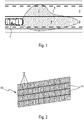
- a light beam emitted by front headlamps has a first lighting zone 4 extending to the ground of track 2 on which the vehicle 1 is traveling, and a second lighting zone 5 extending to the ground of track 3 .
- the second lighting zone 5 has a cutout 6 so that the area of the second lighting zone 5 is less than the area of the first lighting zone 4.
- Cut 6 makes it possible not to dazzle a driver of a vehicle traveling on track 3.
- each front headlight to pivot about a vertical axis.
- LED light-emitting diodes
- a lighting module for a motor vehicle comprising at least two lighting units, each lighting unit comprising at least one light source of the semiconductor light emitting type and means for controlling the light source, the means for controlling the lighting units being independent of each other, each lighting unit comprising a illumination element configured to be illuminated by said at least one illumination source such that a light beam emitted by the light source has a light distribution on a plane dependent on a shape of the illumination element.
- Such a module due to the use of LEDs, is advantageous insofar as the LEDs consume little energy, have a long lifespan and generate only less heating. LEDs also make it possible to vary the shapes of the headlamps and thus create light signatures for certain vehicle models.
- the aim of the present invention is to remedy these drawbacks.
- the invention relates to a lighting device according to claim 1.
- the cut-off of the beam is for example generated by one of the non-parallel sides of one of the trapezoids, called the first lighting unit, while, when the track on which is traveling the vehicle winds, in particular in a bend, it suffices to turn off the first lighting unit and to turn on only another trapezoid, called the second lighting unit, the beam cut being then generated by one of the sides not parallel to the second lighting unit.
- the device comprises at least three light sources and three illumination elements, the third illumination element extending from the large base of the first trapezoid-shaped element in a direction opposite to the elements. edges of the second complementary element of the first illumination element.
- the device comprises a strip of at least three illumination elements in the shape of a trapezoid aligned.
- the device comprises an infinity projection module at the output of the matrix of illumination elements.
- the infinity projection module comprises at least one lens.
- the device comprises two lenses and a light ray filtration diaphragm arranged between the two lenses.
- the subject of the invention is also a lighting system for a motor vehicle comprising two lighting devices as described above.
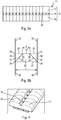
- the lighting device 10 comprises a matrix 11 of illumination elements 12 and a matrix 13 of light sources 14 of the semiconductor light emitting type, for example a light-emitting diode (LED).
- LED light-emitting diode
- the lighting device 10 also comprises a means for controlling each light source, not shown.
- each LED is independent of each other, so that each LED is on or off independently of the other LEDs of the matrix 13.
- Each illumination element 12 is associated with one of the light sources 14 and configured to be illuminated by the associated LED source so that a light beam emitted by the light source 14 has a shape depending on a shape of the illumination element 12, as will be explained in more detail below.
- the array 11 of illumination elements 12 comprises at least a first illumination element 15 and a second illumination element 16.
- the first illumination element 15 has the general shape of a trapezoid 20, preferably isosceles.
- Each isosceles trapezoid 20 is provided with two parallel opposite sides 21, 22, called bases, such that one of the bases, called large base 21, has a length L greater than a length I of the other base 22, called small base.
- Each isosceles trapezoid 20 is also provided with two sides 23, 24 not parallel to one another and connecting the large base 21 and the small base 22.
- the two sides 23 and 24 are of the same length.
- the sides 23 have an upward slope and allow a cut-off of the low beam for right-hand drive, as will be detailed below.
- the sides 24 have a downward slope and allow a cut-off of the low beam for driving on the left, as will be detailed below.
- the large base 21 extends between two opposite ends referenced 25, 26.
- the small base 22 extends between two opposite ends referenced 27 and 28.
- the end 27 of the small base 22 is arranged opposite the end 25 of the large base 21, while the end 28 of the small base 22 is arranged opposite the end 26 of the large base 21.
- the second illumination element 16 is a counter-shape of the first illumination element 15 in the form of a trapezoid, that is to say that the second illumination element has a shape which is partially complementary to the trapezoidal shape.
- the second illumination element comprises two edges 29, 30.
- Edge 29 extends from the end 25 of the large base 21 of the trapezoid 20, while the edge 30 extends from the end 26 of the large base 21.
- edges 29 and 30 are substantially parallel to one another, being spaced apart by a length of the order of the length L of the large base 21.
- the second illumination element 16 comprises two portions 31, 32 arranged on either side of the large base 21 up to the small base 22.
- the portion 31 has a substantially triangular area filling a space delimited by the side 23, a segment 33 extending from the end 27 of the trapezoid 20 to a projection 34 of the end 25 on an axis carrying the small base 22 , as well as a segment 35 extending from the end 25 to the projection 34.
- the portion 32 has a substantially triangular area filling a space delimited by the side 24, a segment 36 extending from the end 28 of the trapezoid 20 to a projection 37 of the end 26 on the bearing axis. the small base 22, as well as a segment 38 extending from the end 26 to the projection 37.
- the shape of the illumination element 16 against the trapezoidal shape of the trapezoid 20 provides illumination of the portions 31 and 32 during the use of the illumination device 10, as will be detailed below.
- the array (11) of illumination elements (12) also comprises at least one third illumination element 17.
- the third illumination element 17 extends from the large base 21 of the first trapezoidal element 15 20 in a direction opposite to the edges 29, 30 of the second element 16.
- the third illumination element 17 comprises two edges 39, 40 substantially parallel to one another, the edge 39 running in an extension of the edge 29 and the edge 40 running in an extension of the edge 30.
- the illumination matrix comprises a plurality of pairs of a first, second and third illumination element aligned.
- each illumination element is a microlens.
- the microlens have dimensions of substantially the same order of magnitude as an LED.
- the microlens is a spherical lens, a focal point of which is disposed behind the array of LEDs, which makes it possible to generate an enlarged virtual image behind the array of LEDs and which is projected by a projection module 50 at infinity.
- the infinity projection module is placed at the output of the matrix of illumination elements.
- the projection module includes at least one projection lens.
- the projection module 50 comprises an input lens 51, an output lens 52, and a light ray filtration diaphragm 53 arranged between the two lenses 51 and 52.
- the input lens 51 creates a virtual image of the image of the matrix shaped by the illumination matrix.
- the exit lens 52 is a projection lens of the virtual image created by the entrance lens 51.
- the diaphragm 53 is an opaque wall provided with a central opening 54 for filtering light rays coming from an LED and passing through a microlens not associated with this LED.
- the diaphragm 53 thus makes it possible to avoid generating ghost images.
- the figure 7 illustrates a view of the lighting device 10 when all the LEDs are on.
- this case corresponds to a use in high beam of the lighting device 10.
- the shape of the second illumination elements 16 counter-shaped to the trapezoids 20 provides illumination uniform by the matrix 11, including in the portions 31 and 32.
- the figures 8 to 10 illustrate lighting emitted by an optical system of the front headlight type for a motor vehicle comprising a first 10 and a second 10 ′ identical lighting devices juxtaposed.
- the two lighting devices 10, 10 ' are arranged so that an offset of half the width at half the height of one of the isosceles trapezoids 20 is generated.
- the offset configuration ensures a doubling of the light intensity produced by the projector in the areas where the two beams emitted by the lighting modules 10 and 10 'overlap.
- the offset configuration of the two modules also ensures a doubling of the resolution of the projector since the beam cutoff 6 is successively formed by a side 23 of the first module 10 then a side 23 ′ of the second module 10 ′.
- a first mode of operation corresponds to a case of operation in low beam, when the road is in a straight line, for driving on the right.
- the trapezoids 20, 20 'corresponding to positive abscissas of the two lighting devices 10 and 10' are illuminated, while the trapezoids 20, 20 'corresponding to negative abscissas are extinguished.
- Cut-off 6 of the low beam beam is formed by side 23 of trapezoid 20-0 corresponding to the smallest positive values of abscissas and ordinates.
- the third elements 17 are all lit while the second illumination elements 16 are all off.
- a second operating mode corresponds to a case of operating in low beam, when the road makes a right turn, for driving on the right.
- the third elements 17 are all lit while the second illumination elements 16 are all off.
- Cut-off 6 of the low beam beam is formed by side 23 of the trapezoid referenced 20+ on the figure 9 .
- the headlight continues to illuminate the road without dazzling a driver of a vehicle traveling in the opposite direction.
- the lighting device also comprises means for controlling the lighting of the matrix 13 of LEDs to a sensor of a path parameter of a motor vehicle.
- the sensor is advantageously an angle of rotation of a steering wheel of the motor vehicle, the path parameter indicating a deviation from a road on which the vehicle is traveling relative to a straight line, such as, in particular, a bend.
- a third operating mode corresponds to a case of operation in low beam, when the road is in a straight line, for driving on the left.
- the trapezoids 20, 20 'corresponding to negative abscissas of the two lighting devices 10 and 10' are illuminated, while the trapezoids 20, 20 'corresponding to positive abscissas are extinguished.
- Cut-off 6 of the low beam beam is formed by side 24 of trapezoid 20-0 corresponding to the largest negative values of abscissa and ordinate.
- the third elements 17 are all lit while the second illumination elements 16 are all off.
- a fourth operating mode corresponds to a case of high beam operation.
- this case corresponds to a use in high beam of the lighting devices 10, 10 ', when a vehicle has been detected in the direction opposite to the vehicle equipped with the lighting devices.
- the shape of the second illumination elements 16 counter-shaped to the trapezoids 20 ensures uniform illumination by the matrix 11, including in the portions 31 and 32.
- the present invention has the advantage of generating a light beam for a low beam, the cut of which follows the trajectory of the vehicle on a winding road, due to a discretization of the beam into successive inverted isosceles trapezoids.
- the discretization according to the present invention also allows adaptation to a vehicle for driving on the right as well as a vehicle for driving on the left, and even allows a change of right or left driving for a given vehicle.
- the trapezoidal discretization also allows adaptation to a non-dazzling high beam for another vehicle.
- the present invention makes it possible to perform various functions, such as directional low beam, left and right hand drive, and glare-free high beam.
- Another advantage of the invention lies in the uniform illumination made possible by the association of the trapezoids and the counter-shapes of the trapezoids, as already indicated.
Landscapes
- Engineering & Computer Science (AREA)
- General Engineering & Computer Science (AREA)
- Physics & Mathematics (AREA)
- Microelectronics & Electronic Packaging (AREA)
- Optics & Photonics (AREA)
- Mathematical Physics (AREA)
- Mechanical Engineering (AREA)
- Non-Portable Lighting Devices Or Systems Thereof (AREA)
- Lighting Device Outwards From Vehicle And Optical Signal (AREA)
Description
- L'invention a pour objet un dispositif d'éclairage pour véhicule automobile.
- L'invention est particulièrement adaptée à un projecteur d'éclairage en feu de croisement et feu de route pour véhicule automobile.
- Il est illustré à la
figure 1 un véhicule automobile 1 se déplaçant sur une voie de circulation 2 adjacente d'une autre voie 3. - En mode feu de croisement, comme illustré à la
figure 1 , un faisceau lumineux émis par des projecteurs avant présente une première zone d'éclairage 4 s'étendant au sol de la voie 2 sur laquelle circule le véhicule 1, et une deuxième zone d'éclairage 5 s'étendant au sol de la voie 3. - Il est connu que la deuxième zone d'éclairage 5 présente une coupure 6 de sorte que l'aire de la deuxième zone d'éclairage 5 soit inférieure à l'aire de la première zone d'éclairage 4.
- La coupure 6 permet de ne pas éblouir un conducteur d'un véhicule circulant sur la voie 3.
- Il est également connu d'asservir la direction du faisceau émis par les projecteurs avant du véhicule automobile à un angle de rotation du volant, ce qui assure que la direction du faisceau suive la géométrie de la voie sur laquelle circule le véhicule, et en particulier la trajectoire du véhicule dans un virage.
- Pour ce faire, on recourt généralement à un système mécanique permettant de faire pivoter chaque projecteur avant autour d'un axe vertical.
- Par ailleurs, il est de plus en plus répandu dans le domaine automobile, d'utiliser comme source de lumière pour les projecteurs des matrices de diodes électroluminescentes (LED).
- Ainsi, il est connu un module d'éclairage pour véhicule automobile, comprenant au moins deux unités d'éclairage, chaque unité d'éclairage comprenant au moins une source de lumière de type émetteur de lumière à semi-conducteur et un moyen de commande de la source de lumière, les moyen de commande des unités d'éclairage étant indépendants les uns des autres, chaque unité d'éclairage comprenant un élément d'illumination configuré pour être éclairé par ladite au moins une source d'éclairage de sorte qu'un faisceau lumineux émis par la source de lumière présente une distribution lumineuse sur un plan dépendant d'une forme de l'élément d'illumination.
- Un tel module, du fait de l'utilisation de LED, est avantageux dans la mesure où les LED consomment peu d'énergie, sont d'une durée de vie longue et ne génèrent qu'un moindre échauffement. Les LED permettent également de faire varier les formes des projecteurs et de créer ainsi des signatures lumineuses pour certains modèles de véhicules.
- Néanmoins, de telles matrices de LED sont difficilement compatibles avec le système mécanique de pivotement de projecteur.
- Le but de la présente invention est de remédier à ces inconvénients.
- A cet effet, l'invention a pour objet un dispositif d'éclairage selon la revendication 1.
- Ainsi, grâce à la présente invention, il est possible de générer un faisceau lumineux uniforme permis par l'association des trapèzes et des contre-formes de trapèzes.
- Il est également possible de réaliser un faisceau lumineux en mode feu de croisement qui suive la géométrie de la route sans avoir à recourir à un système mécanique pivotant.
- En effet, lorsque la route est en ligne droite, la coupure du faisceau est par exemple générée par l'un des côtés non parallèles de l'un des trapèzes, appelée première unité d'éclairage, tandis que, lorsque la voie sur laquelle circule le véhicule serpente, en particulier dans un virage, il suffit d'éteindre la première unité d'éclairage et d'allumer uniquement un autre trapèze, appelé deuxième unité d'éclairage, la coupure du faisceau étant alors générée par l'un des côtés non parallèles de la deuxième unité d'éclairage.
- Selon une autre caractéristique de l'invention, le dispositif comprend au moins trois sources de lumière et trois éléments d'illumination, le troisième élément d'illumination s'étendant depuis la grande base du premier élément en forme de trapèze dans un sens opposé aux bords du deuxième élément complémentaire du premier élément d'illumination.
- Selon une autre caractéristique de l'invention, le dispositif comprend une barrette d'au moins trois éléments d'illumination en forme de trapèze alignés.
- Selon une autre caractéristique de l'invention, le dispositif comprend un module de projection à l'infini en sortie de la matrice d'éléments d'illumination.
- Selon une autre caractéristique de l'invention, le module de projection à l'infini comprend au moins une lentille.
- Selon une autre caractéristique de l'invention, le dispositif comprend deux lentilles et un diaphragme de filtration de rayons lumineux disposé entre les deux lentilles.
- L'invention a également pour objet un système d'éclairage pour véhicule automobile comprenant deux dispositifs d'éclairage tels que décrits précédemment.
- D'autres caractéristiques et avantages de l'invention apparaîtront encore à la lecture de la description qui va suivre. Celle-ci est purement illustrative et doit être lue en regard des dessins annexés sur lesquels :
- la
figure 1 illustre une vue de dessus d'un véhicule automobile circulant sur une route en éclairant la route en feu de croisement, comme déjà décrit ; - la
figure 2 illustre une vue en perspective de côté d'une matrice de sources de lumière d'un dispositif d'éclairage selon la présente invention ; - la
figure 3a illustre une vue de devant d'une matrice d'éléments d'illumination associée à la matrice de lafigure 2 ; - la
figure 3b illustre un détail de lafigure 3a ; - la
figure 4 illustre une vue en perspective de côté de la matrice d'éléments de mise en forme de lafigure 3a ; - la
figure 5 illustre une vue en perspective du dispositif d'éclairage selon la présente invention muni d'un module de projection lumineuse ; - la
figure 6 illustre une vue en perspective du module de projection lumineuse de lafigure 5 ; - la
figure 7 illustre le dispositif d'éclairage de l'invention selon un mode d'éclairage en feu route; - la
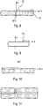
figure 8 illustre deux dispositifs d'éclairage de l'invention selon un premier mode d'éclairage ; - la
figure 9 illustre deux dispositifs d'éclairage de l'invention selon un deuxième mode d'éclairage ; - la
figure 10 illustre deux dispositifs d'éclairage de l'invention selon un troisième mode d'éclairage ; et - la
figure 11 illustre deux dispositifs d'éclairage de l'invention selon un quatrième mode d'éclairage. - Comme visible sur les
figures 2 ,3a et 4 , le dispositif d'éclairage 10 selon la présente invention comprend une matrice 11 d'éléments d'illumination 12 et une matrice 13 de sources de lumières 14 de type émetteur de lumière à semi-conducteur, par exemple une diode électroluminescente (LED). - Le dispositif d'éclairage 10 comprend également un moyen de commande de chaque source de lumière, non représenté.
- Les moyens de commande de chaque LED sont indépendants les uns des autres, de sorte que chaque LED est allumée ou éteinte indépendamment des autres LED de la matrice 13.
- Chaque élément d'illumination 12 est associé à l'une des sources de lumière 14 et configuré pour être éclairé par la source LED associée de sorte qu'un faisceau lumineux émis par la source de lumière 14 présente une forme dépendant d'une forme de l'élément d'illumination 12, comme il va être expliqué plus en détail ci-après.
- La matrice 11 d'éléments d'illumination 12 comprend au moins un premier élément d'illumination 15 et un deuxième élément d'illumination 16.
- Comme visible sur les
figures 3a, 3b et 4 , le premier élément d'illumination 15 présente une forme générale de trapèze 20, de préférence isocèle. - Chaque trapèze isocèle 20 est muni de deux côtés opposés parallèles 21, 22, appelés bases, tels que l'une des bases, dite grande base 21, est d'une longueur L plus élevée qu'une longueur I de l'autre base 22, dite petite base.
- Chaque trapèze isocèle 20 est également muni de deux côtés 23, 24 non parallèles l'un à l'autre et reliant la grande base 21 et la petite base 22.
- Les deux côtés 23 et 24 sont d'une même longueur.
- Les côtés 23 présentent une pente ascendante et permettent une coupure de faisceau de feu de croisement pour une conduite à droite, comme il va être détaillé plus loin.
- Les côtés 24 présentent une pente descendante et permettent une coupure de faisceau de feu de croisement pour une conduite à gauche, comme il va être détaillé plus loin.
- La grande base 21 s'étend entre deux extrémités opposées référencées 25, 26.
- La petite base 22 s'étend entre deux extrémités opposées référencées 27 et 28.
- L'extrémité 27 de la petite base 22 est disposée en regard de l'extrémité 25 de la grande base 21, tandis que l'extrémité 28 de la petite base 22 est disposée en regard de l'extrémité 26 de la grande base 21.
- Le deuxième élément d'illumination 16 est une contre-forme du premier élément d'illumination 15 en forme de trapèze, c'est-à-dire que le deuxième élément d'illumination présente une forme partiellement complémentaire de la forme en trapèze.
- Le deuxième élément d'illumination comprend deux bords 29, 30.
- Le bord 29 s'étend depuis l'extrémité 25 de la grande base 21 du trapèze 20, tandis que le bord 30 s'étend depuis l'extrémité 26 de la grande base 21.
- Les bords 29 et 30 sont sensiblement parallèles l'un à l'autre, en étant distants d'une longueur de l'ordre de la longueur L de la grande base 21.
- Le deuxième élément d'illumination 16 comprend deux portions 31, 32 disposées de part et d'autre de la grande base 21 jusqu'à la petite base 22.
- La portion 31 présente une aire sensiblement triangulaire comblant un espace délimité par le côté 23, un segment 33 s'étendant depuis l'extrémité 27 du trapèze 20 jusqu'à une projection 34 de l'extrémité 25 sur un axe portant la petite base 22, ainsi qu'un segment 35 s'étendant depuis l'extrémité 25 jusqu'à la projection 34.
- De même, la portion 32 présente une aire sensiblement triangulaire comblant un espace délimité par le côté 24, un segment 36 s'étendant depuis l'extrémité 28 du trapèze 20 jusqu'à une projection 37 de l'extrémité 26 sur l'axe portant la petite base 22, ainsi qu'un segment 38 s'étendant depuis l'extrémité 26 jusqu'à la projection 37.
- La forme de l'élément d'illumination 16 en contre-forme du trapèze 20 assure une illumination des portions 31 et 32 au cours de l'utilisation du dispositif d'éclairage 10, comme il va être détaillé par la suite.
- La matrice (11) d'éléments d'illumination (12) comprend également au moins un troisième élément d'illumination 17.
- Le troisième élément d'illumination 17 s'étend depuis la grande base 21 du premier élément 15 en forme de trapèze 20 dans un sens opposé aux bords 29, 30 du deuxième élément 16.
- En d'autres termes, le troisième élément d'illumination 17 comprend deux bords 39, 40 sensiblement parallèles l'un à l'autre, le bord 39 se dirigeant dans un prolongement du bord 29 et le bord 40 se dirigeant dans un prolongement du bord 30.
- Sur le mode de réalisation illustré, la matrice d'illumination comprend une pluralité de couples d'un premier, deuxième et troisième éléments d'illumination alignés.
- Selon l'invention, chaque élément d'illumination est une microlentille.
- La microlentille présente des dimensions sensiblement du même ordre de grandeur qu'une LED.
- De préférence, la microlentille est une lentille sphérique, dont un foyer est disposé en arrière de la matrice de LED, ce qui permet de générer une image virtuelle agrandie en arrière de la matrice de LED et qui est projetée par un module 50 de projection à l'infini.
- Le module de projection à l'infini est disposé en sortie de la matrice d'éléments d'illumination.
- Le module de projection comprend au moins une lentille de projection.
- Sur le mode de réalisation illustré à la
figure 6 , le module de projection 50 comprend une lentille d'entrée 51, une lentille de sortie 52, et un diaphragme 53 de filtration de rayons lumineux disposé entre les deux lentilles 51 et 52. - La lentille d'entrée 51 crée une image virtuelle de l'image de la matrice mise en forme par la matrice d'illumination.
- La lentille de sortie 52 est une lentille de projection de l'image virtuelle créée par la lentille d'entrée 51.
- Le diaphragme 53 est une paroi opaque muni d'une ouverture centrale 54 pour filtrer des rayons lumineux issus d'une LED et traversant une microlentille non associée à cette LED.
- Le diaphragme 53 permet ainsi s'éviter de générer des images fantômes.
- La
figure 7 illustre une vue du dispositif d'éclairage 10 quand toutes les LED sont allumées. - Généralement, ce cas correspond à une utilisation en feu de route du dispositif d'éclairage 10.
- Comme visible sur la
figure 7 , la forme des deuxièmes éléments d'illumination 16 en contre-forme des trapèzes 20 assure un éclairage uniforme par la matrice 11, y compris dans les portions 31 et 32. - Les
figures 8 à 10 illustrent un éclairage émis par un système optique de type projecteur avant pour véhicule automobile comprenant un premier 10 et un deuxième 10' dispositifs d'éclairage identiques juxtaposés. - Les deux dispositifs d'éclairage 10, 10' sont disposés de sorte que soit généré un décalage d'une demi-largeur à mi-hauteur de l'un des trapèzes isocèles 20.
- La configuration en décalage assure un doublement de l'intensité lumineuse produite par le projecteur dans les zones où les deux faisceaux émis par les modules d'éclairage 10 et 10' se recouvrent.
- La configuration en décalage des deux modules assure également un doublement de résolution du projecteur puisque la coupure de faisceau 6 est successivement constituée par un côté 23 du premier module 10 puis un côté 23' du deuxième module 10'.
- Un premier mode de fonctionnement correspond à un cas de fonctionnement en feu de croisement, quand la route est en ligne droite, pour une conduite à droite.
- Comme visible sur la
figure 8 , les trapèzes 20, 20' correspondant à des abscisses positifs des deux dispositifs d'éclairage 10 et 10' sont éclairés, tandis que les trapèzes 20, 20' correspondant à des abscisses négatifs sont éteints. - La coupure 6 du faisceau en feu de croisement est constituée par le côté 23 du trapèze 20-0 correspondant aux plus petites valeurs positives d'abscisses et d'ordonnées.
- Les troisièmes éléments 17 sont tous éclairés tandis que les deuxièmes éléments d'illumination 16 sont tous éteints.
- Un deuxième mode de fonctionnement correspond à un cas de fonctionnement en feu de croisement, quand la route fait un virage à droite, pour une conduite à droite.
- Comme visible sur la
figure 9 , seule une partie à droite des trapèzes 20 (correspondant à des valeurs strictement positives d'abscisses) tandis que les autres trapèzes sont éteints. - Comme pour la
figure 8 , les troisièmes éléments 17 sont tous éclairés tandis que les deuxièmes éléments d'illumination 16 sont tous éteints. - La coupure 6 du faisceau en feu de croisement est constituée par le côté 23 du trapèze référencé 20+ sur la
figure 9 . - Ainsi, dans un virage à droite, le projecteur continue d'éclairer la route sans éblouir un conducteur d'un véhicule circulant en sens opposé.
- On note que, avantageusement, le dispositif d'éclairage comprend également des moyens d'asservissement de l'éclairage de la matrice 13 de LED à un capteur d'un paramètre de trajectoire d'un véhicule automobile.
- Le capteur est avantageusement un angle de rotation d'un volant du véhicule automobile, le paramètre de trajectoire indiquant une déviation d'une route sur laquelle circule le véhicule relativement à une ligne droite, telle que, en particulier, un virage.
- Un troisième mode de fonctionnement correspond à un cas de fonctionnement en feu de croisement, quand la route est en ligne droite, pour une conduite à gauche.
- Comme visible sur la
figure 10 , les trapèzes 20, 20' correspondant à des abscisses négatifs des deux dispositifs d'éclairage 10 et 10' sont éclairés, tandis que les trapèzes 20, 20' correspondant à des abscisses positifs sont éteints. - La coupure 6 du faisceau en feu de croisement est constituée par le côté 24 du trapèze 20-0 correspondant aux plus grandes valeurs négatives d'abscisses et d'ordonnées.
- Les troisièmes éléments 17 sont tous éclairés tandis que les deuxièmes éléments d'illumination 16 sont tous éteints.
- Un quatrième mode de fonctionnement correspond à un cas de fonctionnement en feu de route.
- Comme visible sur la
figure 11 , toutes les LED sont allumées à l'exception d'un couple de premier élément 15 et deuxième élément 16. - Généralement, ce cas correspond à une utilisation en feu de route des dispositifs d'éclairage 10, 10', quand un véhicule a été détecté en sens opposé au véhicule équipé des dispositifs d'éclairage.
- Comme visible sur la
figure 11 , la forme des deuxièmes éléments d'illumination 16 en contre-forme des trapèzes 20 assure un éclairage uniforme par la matrice 11, y compris dans les portions 31 et 32. - La présente invention présente l'avantage de générer un faisceau lumineux pour feu de croisement dont la coupure suit la trajectoire du véhicule sur une route sinueuse, du fait d'une discrétisation du faisceau en trapèzes isocèles successifs inversés.
- La discrétisation selon la présente invention permet également une adaptation à un véhicule pour conduite à droite tout comme à un véhicule pour conduite à gauche, et permet même un changement de conduite droite ou gauche pour un véhicule donné.
- La discrétisation en trapèzes permet également une adaptation à un feu de route non éblouissant pour un autre véhicule.
- Ainsi, la présente invention permet de réaliser différentes fonctions, telles que feu de croisement directionnel, conduite à gauche et à droite, et feu de route non éblouissant.
- Un autre avantage de l'invention réside dans l'éclairage uniforme permis par l'association des trapèzes et des contre-formes de trapèzes, comme déjà indiqué.
Claims (7)
- Dispositif d'éclairage pour véhicule automobile, comprenant une matrice d'au moins deux sources de lumière de type émetteur de lumière à semi-conducteur et une matrice d'au moins un premier (15) et un deuxième (16) éléments d'illumination, chaque élément d'illumination étant une microlentille associée à l'une des sources de lumière et configurée pour être éclairée par ladite source de lumière associée de sorte qu'un faisceau lumineux émis par la source de lumière présente une forme dépendant d'une forme de l'élément d'illumination, caractérisé en ce que le premier élément d'illumination (15) présente une face de sortie de la lumière en forme de trapèze muni de deux côtés opposés parallèles (21, 22), appelés bases, tels que l'une des bases, dites grande base (21), est d'une longueur plus élevée qu'une longueur de l'autre base, dite petite base (22), ledit trapèze (20) étant également muni de deux côtés non parallèles (23, 24) l'un à l'autre et reliant la grande base (21) et la petite base (22), et le deuxième élément d'illumination (16) présente une forme partiellement complémentaire de la forme en trapèze, en contre forme du trapèze (20), et comprend deux portions (31, 32) d'aires triangulaires disposées de part et d'autre de la grande base (21) jusqu'à la petite base (22) deux bords (29 , 30) s'étendant depuis deux extrémités opposées de la grande base (21), parallèlement l'un à l'autre, en direction de la petite base (22) en étant distants d'au moins une longueur de l'ordre de la longueur de la grande base (21).
- Dispositif d'éclairage selon la revendication 1, comprenant au moins trois sources de lumière et trois éléments d'illumination (15, 16, 17), le troisième élément d'illumination (17) s'étendant depuis la grande base (21) du premier élément (15) en forme de trapèze (20) dans un sens opposé aux bords du deuxième élément (16) complémentaire du premier élément d'illumination (15).
- Dispositif d'éclairage selon l'une des revendications 1 ou 2, comprenant une barrette d'au moins trois éléments d'illumination en forme de trapèze alignés (12).
- Dispositif d'éclairage selon l'une des revendications précédentes, comprenant un module de projection à l'infini (50) en sortie de la matrice (11) d'éléments d'illumination (12).
- Dispositif d'éclairage selon la revendication précédente, dans lequel le module de projection à l'infini (50) comprend au moins une lentille.
- Dispositif d'éclairage selon la revendication précédente, comprenant deux lentilles (51, 52) et un diaphragme (53) de filtration de rayons lumineux disposé entre les deux lentilles (51, 52).
- Système d'éclairage pour véhicule automobile, comprenant deux dispositifs d'éclairage (10, 10') selon l'une des revendications 1 à 6.
Applications Claiming Priority (1)
| Application Number | Priority Date | Filing Date | Title |
|---|---|---|---|
| FR1756398A FR3068658B1 (fr) | 2017-07-06 | 2017-07-06 | Dispositif d'eclairage d'un vehicule automobile |
Publications (2)
| Publication Number | Publication Date |
|---|---|
| EP3425267A1 EP3425267A1 (fr) | 2019-01-09 |
| EP3425267B1 true EP3425267B1 (fr) | 2021-09-15 |
Family
ID=60515465
Family Applications (1)
| Application Number | Title | Priority Date | Filing Date |
|---|---|---|---|
| EP18181752.9A Active EP3425267B1 (fr) | 2017-07-06 | 2018-07-04 | Dispositif d'eclairage d'un vehicule automobile |
Country Status (5)
| Country | Link |
|---|---|
| US (1) | US10845019B2 (fr) |
| EP (1) | EP3425267B1 (fr) |
| JP (1) | JP7175653B2 (fr) |
| CN (1) | CN109210484B (fr) |
| FR (1) | FR3068658B1 (fr) |
Families Citing this family (3)
| Publication number | Priority date | Publication date | Assignee | Title |
|---|---|---|---|---|
| CN209944211U (zh) * | 2019-03-29 | 2020-01-14 | 曼德电子电器有限公司 | 车辆近光配光结构 |
| CN110220158B (zh) * | 2019-05-20 | 2020-04-21 | 华域视觉科技(上海)有限公司 | 车灯用光学装置、汽车照明装置及汽车 |
| KR20230027424A (ko) * | 2021-08-19 | 2023-02-28 | 현대모비스 주식회사 | 차량용 조명장치 |
Family Cites Families (18)
| Publication number | Priority date | Publication date | Assignee | Title |
|---|---|---|---|---|
| DE102008013603B4 (de) * | 2008-03-11 | 2017-06-22 | Automotive Lighting Reutlingen Gmbh | Lichtmodul für eine Beleuchtungseinrichtung |
| CN101699134A (zh) * | 2008-04-30 | 2010-04-28 | 麦格纳国际公司 | 紧凑型高效光学器件 |
| DE102008044967B4 (de) * | 2008-08-29 | 2010-10-07 | Daimler Ag | Beleuchtungsvorrichtung mit mehreren Halbleiterlichtquellen |
| DE102010023360A1 (de) | 2009-10-05 | 2011-04-07 | Automotive Lighting Reutlingen Gmbh | Zur Erzeugung verschiedener Lichtverteilungen eingerichteter Kraftfahrzeugscheinwerfer mit Halbleiterlichtquellen |
| JP5582865B2 (ja) * | 2010-05-12 | 2014-09-03 | 株式会社小糸製作所 | 灯具 |
| DE102011005582A1 (de) * | 2011-03-15 | 2012-09-20 | Automotive Lighting Reutlingen Gmbh | Beleuchtungseinrichtung für ein Kraftfahrzeug mit einer redundanten Ansteuerung von Lichtquellen |
| AT513738B1 (de) * | 2012-12-20 | 2014-07-15 | Zizala Lichtsysteme Gmbh | Leuchteinheit für einen Scheinwerfer |
| JP2015013512A (ja) | 2013-07-03 | 2015-01-22 | スタンレー電気株式会社 | 車両用前照灯、車両用前照灯システム |
| DE102013217843A1 (de) * | 2013-09-06 | 2015-03-12 | Automotive Lighting Reutlingen Gmbh | Projektionsoptik zum Einsatz in einem LED-Modul eines Kraftfahrzeugscheinwerfers, sowie LED-Modul und Kraftfahrzeugscheinwerfer mit einer solchen Projektionsoptik |
| AT514967B1 (de) * | 2013-10-25 | 2015-08-15 | Zizala Lichtsysteme Gmbh | Mikroprojektions-Lichtmodul für einen Kraftfahrzeugscheinwerfer |
| US10168018B2 (en) * | 2014-02-25 | 2019-01-01 | Ford Global Technologies, Llc | Vehicle light fixture having internal heatsink for LED lamp |
| DE102014110282A1 (de) * | 2014-07-22 | 2016-01-28 | Hella Kgaa Hueck & Co. | Beleuchtungsvorrichtung für Fahrzeuge |
| DE102015119718A1 (de) * | 2014-11-24 | 2016-05-25 | Ford Global Technologies, Llc | Hochwirksame Fahrzeug-LED-Module und Scheinwerfer mit einem niedrigen Profil |
| FR3039629B1 (fr) * | 2015-07-28 | 2020-08-14 | Valeo Vision | Dispositif d'eclairage pour projecteur de vehicule automobile |
| FR3039630A1 (fr) * | 2015-07-28 | 2017-02-03 | Valeo Vision | Systeme d'eclairage pour projecteur de vehicule automobile |
| AT517887B1 (de) * | 2015-10-23 | 2018-06-15 | Zkw Group Gmbh | Mikroprojektions-Lichtmodul für Fahrzeugscheinwerfer |
| KR101754169B1 (ko) | 2016-08-02 | 2017-07-05 | 엘지전자 주식회사 | 차량용 배광기구 |
| CN106641964B (zh) * | 2017-01-19 | 2023-05-16 | 华域视觉科技(上海)有限公司 | 一种具有adb功能的led光源远近光一体车灯模组 |
-
2017
- 2017-07-06 FR FR1756398A patent/FR3068658B1/fr not_active Expired - Fee Related
-
2018
- 2018-07-04 EP EP18181752.9A patent/EP3425267B1/fr active Active
- 2018-07-05 JP JP2018128157A patent/JP7175653B2/ja active Active
- 2018-07-06 US US16/029,137 patent/US10845019B2/en active Active
- 2018-07-06 CN CN201810737398.5A patent/CN109210484B/zh active Active
Also Published As
| Publication number | Publication date |
|---|---|
| CN109210484A (zh) | 2019-01-15 |
| EP3425267A1 (fr) | 2019-01-09 |
| FR3068658A1 (fr) | 2019-01-11 |
| JP7175653B2 (ja) | 2022-11-21 |
| US10845019B2 (en) | 2020-11-24 |
| CN109210484B (zh) | 2022-01-28 |
| US20190011104A1 (en) | 2019-01-10 |
| JP2019023997A (ja) | 2019-02-14 |
| FR3068658B1 (fr) | 2021-04-16 |
Similar Documents
| Publication | Publication Date | Title |
|---|---|---|
| EP3290777B1 (fr) | Module optique pour éclairer des points de portique | |
| EP3002504B1 (fr) | Module lumineux pour l'éclairage d'un véhicule automobile | |
| EP3604910B1 (fr) | Piece optique comprenant un bloc avec un dioptre formant plieuse pour deux faisceaux | |
| EP3181991B1 (fr) | Module d'eclairage automobile avec fonctions code et route combinees et une source lumineuse ajustable | |
| EP3147557B1 (fr) | Element optique primaire pour module lumineux de vehicule automobile | |
| EP3067618B1 (fr) | Dispositif lumineux a guides optiques | |
| EP3636990B1 (fr) | Dispositif d'éclairage pour véhicule automobile comportant un guide de lumière | |
| EP2690352B1 (fr) | Système d'éclairage adaptatif pour véhicule automobile | |
| EP3470728A1 (fr) | Module lumineux pour vehicule automobile | |
| EP1308669A1 (fr) | Dispositif d'éclairage de type elliptique pour véhicule automobile | |
| FR2995967B1 (fr) | Module d'eclairage, notamment pour vehicule automobile | |
| EP3350506B1 (fr) | Dispositif de projection de faisceau lumineux de vehicule automobile et projecteur de vehicule comprenant ledit dispositif | |
| EP3511608B1 (fr) | Module optique pour vehicule automobile | |
| EP3425267A1 (fr) | Dispositif d'eclairage d'un vehicule automobile | |
| EP2767752A1 (fr) | Dispositif d'éclairage et/ou de signalisation à lentille torique | |
| EP3470727A1 (fr) | Module d'éclairage formant un motif lumineux divisé en une portion supérieure aux bords verticaux nets et une portion inférieure aux bords verticaux floux | |
| FR3038695A1 (fr) | Module lumineux pour l'eclairage et/ou la signalisation d'un vehicule automobile | |
| EP2416061A2 (fr) | Module d'éclairage à coupure avec réflecteur parabolique disposé sur un réflecteur elliptique | |
| WO2022269095A1 (fr) | Module optique d'un système lumineux d'un véhicule automobile | |
| WO2017194868A1 (fr) | Système et procédé d'éclairage pour véhicule automobile | |
| FR3056695A1 (fr) | Dispositif d'eclairage pour vehicule automobile comportant un guide de lumiere | |
| EP3276249B1 (fr) | Systeme lumineux pour dispositif d'eclairage et, optionellement, de signalisation d'un vehicule automobile | |
| FR3095494A1 (fr) | Dispositif d’éclairage adaptatif pour projecteur de véhicule |
Legal Events
| Date | Code | Title | Description |
|---|---|---|---|
| PUAI | Public reference made under article 153(3) epc to a published international application that has entered the european phase |
Free format text: ORIGINAL CODE: 0009012 |
|
| STAA | Information on the status of an ep patent application or granted ep patent |
Free format text: STATUS: REQUEST FOR EXAMINATION WAS MADE |
|
| 17P | Request for examination filed |
Effective date: 20180704 |
|
| AK | Designated contracting states |
Kind code of ref document: A1 Designated state(s): AL AT BE BG CH CY CZ DE DK EE ES FI FR GB GR HR HU IE IS IT LI LT LU LV MC MK MT NL NO PL PT RO RS SE SI SK SM TR |
|
| AX | Request for extension of the european patent |
Extension state: BA ME |
|
| STAA | Information on the status of an ep patent application or granted ep patent |
Free format text: STATUS: EXAMINATION IS IN PROGRESS |
|
| 17Q | First examination report despatched |
Effective date: 20200420 |
|
| GRAP | Despatch of communication of intention to grant a patent |
Free format text: ORIGINAL CODE: EPIDOSNIGR1 |
|
| STAA | Information on the status of an ep patent application or granted ep patent |
Free format text: STATUS: GRANT OF PATENT IS INTENDED |
|
| INTG | Intention to grant announced |
Effective date: 20210422 |
|
| GRAS | Grant fee paid |
Free format text: ORIGINAL CODE: EPIDOSNIGR3 |
|
| GRAA | (expected) grant |
Free format text: ORIGINAL CODE: 0009210 |
|
| STAA | Information on the status of an ep patent application or granted ep patent |
Free format text: STATUS: THE PATENT HAS BEEN GRANTED |
|
| AK | Designated contracting states |
Kind code of ref document: B1 Designated state(s): AL AT BE BG CH CY CZ DE DK EE ES FI FR GB GR HR HU IE IS IT LI LT LU LV MC MK MT NL NO PL PT RO RS SE SI SK SM TR |
|
| REG | Reference to a national code |
Ref country code: CH Ref legal event code: EP |
|
| REG | Reference to a national code |
Ref country code: DE Ref legal event code: R096 Ref document number: 602018023500 Country of ref document: DE |
|
| REG | Reference to a national code |
Ref country code: IE Ref legal event code: FG4D Free format text: LANGUAGE OF EP DOCUMENT: FRENCH |
|
| REG | Reference to a national code |
Ref country code: AT Ref legal event code: REF Ref document number: 1430775 Country of ref document: AT Kind code of ref document: T Effective date: 20211015 |
|
| REG | Reference to a national code |
Ref country code: LT Ref legal event code: MG9D |
|
| REG | Reference to a national code |
Ref country code: NL Ref legal event code: MP Effective date: 20210915 |
|
| PG25 | Lapsed in a contracting state [announced via postgrant information from national office to epo] |
Ref country code: SE Free format text: LAPSE BECAUSE OF FAILURE TO SUBMIT A TRANSLATION OF THE DESCRIPTION OR TO PAY THE FEE WITHIN THE PRESCRIBED TIME-LIMIT Effective date: 20210915 Ref country code: RS Free format text: LAPSE BECAUSE OF FAILURE TO SUBMIT A TRANSLATION OF THE DESCRIPTION OR TO PAY THE FEE WITHIN THE PRESCRIBED TIME-LIMIT Effective date: 20210915 Ref country code: HR Free format text: LAPSE BECAUSE OF FAILURE TO SUBMIT A TRANSLATION OF THE DESCRIPTION OR TO PAY THE FEE WITHIN THE PRESCRIBED TIME-LIMIT Effective date: 20210915 Ref country code: FI Free format text: LAPSE BECAUSE OF FAILURE TO SUBMIT A TRANSLATION OF THE DESCRIPTION OR TO PAY THE FEE WITHIN THE PRESCRIBED TIME-LIMIT Effective date: 20210915 Ref country code: NO Free format text: LAPSE BECAUSE OF FAILURE TO SUBMIT A TRANSLATION OF THE DESCRIPTION OR TO PAY THE FEE WITHIN THE PRESCRIBED TIME-LIMIT Effective date: 20211215 Ref country code: BG Free format text: LAPSE BECAUSE OF FAILURE TO SUBMIT A TRANSLATION OF THE DESCRIPTION OR TO PAY THE FEE WITHIN THE PRESCRIBED TIME-LIMIT Effective date: 20211215 Ref country code: LT Free format text: LAPSE BECAUSE OF FAILURE TO SUBMIT A TRANSLATION OF THE DESCRIPTION OR TO PAY THE FEE WITHIN THE PRESCRIBED TIME-LIMIT Effective date: 20210915 |
|
| REG | Reference to a national code |
Ref country code: AT Ref legal event code: MK05 Ref document number: 1430775 Country of ref document: AT Kind code of ref document: T Effective date: 20210915 |
|
| PG25 | Lapsed in a contracting state [announced via postgrant information from national office to epo] |
Ref country code: LV Free format text: LAPSE BECAUSE OF FAILURE TO SUBMIT A TRANSLATION OF THE DESCRIPTION OR TO PAY THE FEE WITHIN THE PRESCRIBED TIME-LIMIT Effective date: 20210915 Ref country code: GR Free format text: LAPSE BECAUSE OF FAILURE TO SUBMIT A TRANSLATION OF THE DESCRIPTION OR TO PAY THE FEE WITHIN THE PRESCRIBED TIME-LIMIT Effective date: 20211216 |
|
| PG25 | Lapsed in a contracting state [announced via postgrant information from national office to epo] |
Ref country code: AT Free format text: LAPSE BECAUSE OF FAILURE TO SUBMIT A TRANSLATION OF THE DESCRIPTION OR TO PAY THE FEE WITHIN THE PRESCRIBED TIME-LIMIT Effective date: 20210915 |
|
| PG25 | Lapsed in a contracting state [announced via postgrant information from national office to epo] |
Ref country code: IS Free format text: LAPSE BECAUSE OF FAILURE TO SUBMIT A TRANSLATION OF THE DESCRIPTION OR TO PAY THE FEE WITHIN THE PRESCRIBED TIME-LIMIT Effective date: 20220115 Ref country code: SM Free format text: LAPSE BECAUSE OF FAILURE TO SUBMIT A TRANSLATION OF THE DESCRIPTION OR TO PAY THE FEE WITHIN THE PRESCRIBED TIME-LIMIT Effective date: 20210915 Ref country code: SK Free format text: LAPSE BECAUSE OF FAILURE TO SUBMIT A TRANSLATION OF THE DESCRIPTION OR TO PAY THE FEE WITHIN THE PRESCRIBED TIME-LIMIT Effective date: 20210915 Ref country code: RO Free format text: LAPSE BECAUSE OF FAILURE TO SUBMIT A TRANSLATION OF THE DESCRIPTION OR TO PAY THE FEE WITHIN THE PRESCRIBED TIME-LIMIT Effective date: 20210915 Ref country code: PT Free format text: LAPSE BECAUSE OF FAILURE TO SUBMIT A TRANSLATION OF THE DESCRIPTION OR TO PAY THE FEE WITHIN THE PRESCRIBED TIME-LIMIT Effective date: 20220117 Ref country code: PL Free format text: LAPSE BECAUSE OF FAILURE TO SUBMIT A TRANSLATION OF THE DESCRIPTION OR TO PAY THE FEE WITHIN THE PRESCRIBED TIME-LIMIT Effective date: 20210915 Ref country code: NL Free format text: LAPSE BECAUSE OF FAILURE TO SUBMIT A TRANSLATION OF THE DESCRIPTION OR TO PAY THE FEE WITHIN THE PRESCRIBED TIME-LIMIT Effective date: 20210915 Ref country code: ES Free format text: LAPSE BECAUSE OF FAILURE TO SUBMIT A TRANSLATION OF THE DESCRIPTION OR TO PAY THE FEE WITHIN THE PRESCRIBED TIME-LIMIT Effective date: 20210915 Ref country code: EE Free format text: LAPSE BECAUSE OF FAILURE TO SUBMIT A TRANSLATION OF THE DESCRIPTION OR TO PAY THE FEE WITHIN THE PRESCRIBED TIME-LIMIT Effective date: 20210915 Ref country code: CZ Free format text: LAPSE BECAUSE OF FAILURE TO SUBMIT A TRANSLATION OF THE DESCRIPTION OR TO PAY THE FEE WITHIN THE PRESCRIBED TIME-LIMIT Effective date: 20210915 Ref country code: AL Free format text: LAPSE BECAUSE OF FAILURE TO SUBMIT A TRANSLATION OF THE DESCRIPTION OR TO PAY THE FEE WITHIN THE PRESCRIBED TIME-LIMIT Effective date: 20210915 |
|
| REG | Reference to a national code |
Ref country code: DE Ref legal event code: R097 Ref document number: 602018023500 Country of ref document: DE |
|
| PLBE | No opposition filed within time limit |
Free format text: ORIGINAL CODE: 0009261 |
|
| STAA | Information on the status of an ep patent application or granted ep patent |
Free format text: STATUS: NO OPPOSITION FILED WITHIN TIME LIMIT |
|
| PG25 | Lapsed in a contracting state [announced via postgrant information from national office to epo] |
Ref country code: DK Free format text: LAPSE BECAUSE OF FAILURE TO SUBMIT A TRANSLATION OF THE DESCRIPTION OR TO PAY THE FEE WITHIN THE PRESCRIBED TIME-LIMIT Effective date: 20210915 |
|
| 26N | No opposition filed |
Effective date: 20220616 |
|
| PG25 | Lapsed in a contracting state [announced via postgrant information from national office to epo] |
Ref country code: SI Free format text: LAPSE BECAUSE OF FAILURE TO SUBMIT A TRANSLATION OF THE DESCRIPTION OR TO PAY THE FEE WITHIN THE PRESCRIBED TIME-LIMIT Effective date: 20210915 |
|
| PG25 | Lapsed in a contracting state [announced via postgrant information from national office to epo] |
Ref country code: IT Free format text: LAPSE BECAUSE OF FAILURE TO SUBMIT A TRANSLATION OF THE DESCRIPTION OR TO PAY THE FEE WITHIN THE PRESCRIBED TIME-LIMIT Effective date: 20210915 |
|
| PG25 | Lapsed in a contracting state [announced via postgrant information from national office to epo] |
Ref country code: MC Free format text: LAPSE BECAUSE OF FAILURE TO SUBMIT A TRANSLATION OF THE DESCRIPTION OR TO PAY THE FEE WITHIN THE PRESCRIBED TIME-LIMIT Effective date: 20210915 |
|
| REG | Reference to a national code |
Ref country code: CH Ref legal event code: PL |
|
| GBPC | Gb: european patent ceased through non-payment of renewal fee |
Effective date: 20220704 |
|
| REG | Reference to a national code |
Ref country code: BE Ref legal event code: MM Effective date: 20220731 |
|
| PG25 | Lapsed in a contracting state [announced via postgrant information from national office to epo] |
Ref country code: LU Free format text: LAPSE BECAUSE OF NON-PAYMENT OF DUE FEES Effective date: 20220704 Ref country code: LI Free format text: LAPSE BECAUSE OF NON-PAYMENT OF DUE FEES Effective date: 20220731 Ref country code: CH Free format text: LAPSE BECAUSE OF NON-PAYMENT OF DUE FEES Effective date: 20220731 |
|
| PG25 | Lapsed in a contracting state [announced via postgrant information from national office to epo] |
Ref country code: GB Free format text: LAPSE BECAUSE OF NON-PAYMENT OF DUE FEES Effective date: 20220704 Ref country code: BE Free format text: LAPSE BECAUSE OF NON-PAYMENT OF DUE FEES Effective date: 20220731 |
|
| P01 | Opt-out of the competence of the unified patent court (upc) registered |
Effective date: 20230528 |
|
| PG25 | Lapsed in a contracting state [announced via postgrant information from national office to epo] |
Ref country code: IE Free format text: LAPSE BECAUSE OF NON-PAYMENT OF DUE FEES Effective date: 20220704 |
|
| PG25 | Lapsed in a contracting state [announced via postgrant information from national office to epo] |
Ref country code: HU Free format text: LAPSE BECAUSE OF FAILURE TO SUBMIT A TRANSLATION OF THE DESCRIPTION OR TO PAY THE FEE WITHIN THE PRESCRIBED TIME-LIMIT; INVALID AB INITIO Effective date: 20180704 |
|
| PG25 | Lapsed in a contracting state [announced via postgrant information from national office to epo] |
Ref country code: MK Free format text: LAPSE BECAUSE OF FAILURE TO SUBMIT A TRANSLATION OF THE DESCRIPTION OR TO PAY THE FEE WITHIN THE PRESCRIBED TIME-LIMIT Effective date: 20210915 Ref country code: CY Free format text: LAPSE BECAUSE OF FAILURE TO SUBMIT A TRANSLATION OF THE DESCRIPTION OR TO PAY THE FEE WITHIN THE PRESCRIBED TIME-LIMIT Effective date: 20210915 |
|
| PG25 | Lapsed in a contracting state [announced via postgrant information from national office to epo] |
Ref country code: TR Free format text: LAPSE BECAUSE OF FAILURE TO SUBMIT A TRANSLATION OF THE DESCRIPTION OR TO PAY THE FEE WITHIN THE PRESCRIBED TIME-LIMIT Effective date: 20210915 |
|
| PG25 | Lapsed in a contracting state [announced via postgrant information from national office to epo] |
Ref country code: MT Free format text: LAPSE BECAUSE OF FAILURE TO SUBMIT A TRANSLATION OF THE DESCRIPTION OR TO PAY THE FEE WITHIN THE PRESCRIBED TIME-LIMIT Effective date: 20210915 |
|
| PGFP | Annual fee paid to national office [announced via postgrant information from national office to epo] |
Ref country code: DE Payment date: 20250711 Year of fee payment: 8 |
|
| PGFP | Annual fee paid to national office [announced via postgrant information from national office to epo] |
Ref country code: FR Payment date: 20250730 Year of fee payment: 8 |