EP3425265A1 - Justierbares scheinwerferlicht - Google Patents
Justierbares scheinwerferlicht Download PDFInfo
- Publication number
- EP3425265A1 EP3425265A1 EP18177430.8A EP18177430A EP3425265A1 EP 3425265 A1 EP3425265 A1 EP 3425265A1 EP 18177430 A EP18177430 A EP 18177430A EP 3425265 A1 EP3425265 A1 EP 3425265A1
- Authority
- EP
- European Patent Office
- Prior art keywords
- board
- headlight
- board unit
- headlamp
- heat sink
- Prior art date
- Legal status (The legal status is an assumption and is not a legal conclusion. Google has not performed a legal analysis and makes no representation as to the accuracy of the status listed.)
- Granted
Links
Images



Classifications
-
- F—MECHANICAL ENGINEERING; LIGHTING; HEATING; WEAPONS; BLASTING
- F21—LIGHTING
- F21S—NON-PORTABLE LIGHTING DEVICES; SYSTEMS THEREOF; VEHICLE LIGHTING DEVICES SPECIALLY ADAPTED FOR VEHICLE EXTERIORS
- F21S45/00—Arrangements within vehicle lighting devices specially adapted for vehicle exteriors, for purposes other than emission or distribution of light
- F21S45/40—Cooling of lighting devices
- F21S45/47—Passive cooling, e.g. using fins, thermal conductive elements or openings
-
- F—MECHANICAL ENGINEERING; LIGHTING; HEATING; WEAPONS; BLASTING
- F21—LIGHTING
- F21S—NON-PORTABLE LIGHTING DEVICES; SYSTEMS THEREOF; VEHICLE LIGHTING DEVICES SPECIALLY ADAPTED FOR VEHICLE EXTERIORS
- F21S41/00—Illuminating devices specially adapted for vehicle exteriors, e.g. headlamps
- F21S41/10—Illuminating devices specially adapted for vehicle exteriors, e.g. headlamps characterised by the light source
- F21S41/19—Attachment of light sources or lamp holders
-
- F—MECHANICAL ENGINEERING; LIGHTING; HEATING; WEAPONS; BLASTING
- F21—LIGHTING
- F21S—NON-PORTABLE LIGHTING DEVICES; SYSTEMS THEREOF; VEHICLE LIGHTING DEVICES SPECIALLY ADAPTED FOR VEHICLE EXTERIORS
- F21S41/00—Illuminating devices specially adapted for vehicle exteriors, e.g. headlamps
- F21S41/60—Illuminating devices specially adapted for vehicle exteriors, e.g. headlamps characterised by a variable light distribution
- F21S41/65—Illuminating devices specially adapted for vehicle exteriors, e.g. headlamps characterised by a variable light distribution by acting on light sources
- F21S41/657—Illuminating devices specially adapted for vehicle exteriors, e.g. headlamps characterised by a variable light distribution by acting on light sources by moving light sources
Definitions
- the invention relates to an adjustable headlamp system for motor vehicles.
- the present invention relates to a headlamp system having a positionally adjustable LED (light emitting diode) light source.
- a headlight may comprise an array of LED modules, each LED module having an LED light source and optics.
- the headlamp system may be configured so that the low beam is provided not only by an LED light source, but by two or more LED modules. By controlling such an array of LED modules, it is possible to variably adjust the light distribution of the headlamp. As a result, the headlight can be adapted, for example, to a changed traffic situation in order to realize a light assistance system.
- a problem with the use of LED light sources is that as much cooling as possible must be provided so as not to reduce the efficiency and the life of the LED light source.
- the cooling must be provided in addition to the electronics, which is required to control the LED light source. It has been assumed that the board on which the LED light source is arranged, must be rigidly attached to the heat sink in order to achieve the required cooling capacity. Both the cooling and the electronics not only limit the available space, but also complicate the realization of an adjustable headlamp system.
- adjustable headlamp systems have proven to be more efficient in terms of lighting technology and can thereby provide higher power. Due to the adjustability, it is possible in particular to compensate for component and joining tolerances.
- Significant adjustable headlight systems are in particular for such headlight systems, which have a primary optics and a secondary optics, which are arranged one after the other in the beam path of the headlight light.
- the position of the primary optic relative to the secondary optics can influence the light-dark border as well as the quality and intensity of the light distribution.
- the adjustability is further for headlight systems in which a light function is provided by means of an array of LED modules.
- a light function is provided by means of an array of LED modules.
- an adjustability of the LED modules relative to each other is advantageous.
- the individual LED modules should be made as small as possible. Due to the small size but also the light characteristic is more sensitive to tolerances.
- the present disclosure particularly shows that a guided movement of the circuit board, on which the light source is arranged, can be realized relative to a heat sink by means of a fixing element, which presses the circuit board against the heat sink during the guided movement.
- the headlamp system may include a circuit board unit.
- the board unit may include a board and a light source.
- the light source can be arranged on the circuit board.
- the light source may be configured to generate spotlight.
- the headlamp system may include a heat sink.
- the heat sink may have a thermal contact surface.
- the board unit may be in contact with the thermal contact surface, ie in particular adjacent to each other.
- the headlamp system may be configured to provide guided movement of the board unit relative to the heat sink. The guided movement can be achieved by means of the thermal contact surface be guided.
- the headlamp system may have a fixing element.
- the fixing member may be configured to push the board unit against the thermal contact surface during the guided movement.
- the light source can be configured as LED (light emitting diode).
- the LED can be arranged on the board.
- the circuit board may have at least part of a circuit for driving the LEDs and / or at least part of a circuit for powering the LED.
- at least some of these functions are integrated on one or more boards, which are arranged separately from the board unit.
- the board may be at least partially formed as a metal core board, in particular as an aluminum core board.
- the board is at least partially configured as an epoxy resin board or as a ceramic board.
- the thermal contact surface may be arranged in a plane.
- the thermal contact surface may be parallel or substantially parallel to a major plane of the board.
- the contact between the thermal contact surface and the board unit may be flat.
- the guided movement may be parallel or substantially parallel to a board main plane of the board.
- the headlamp can be configured so that the board unit via the thermal contact surface one-dimensional or two-dimensionally guided is movable.
- the fixing member may fix the board unit relative to the heat sink in a direction perpendicular to the plane of the heat contact surface.
- One or more headlamp optical elements emitted from the light source may be fixedly connected to the board. These components can be part of the board unit.
- Optical elements can be, for example, lenses, mirrors or diaphragms.
- the mirrors can be plane mirrors, concave mirrors or convex mirrors.
- a surface of a side of the board unit facing away from the light source is in heat-conductive contact with the heat-contact surface, i. especially contiguous.
- the heat-conducting contact takes place at least partially by means of a heat-conducting means of the headlight system.
- the heat conducting means may comprise, for example, a thermal compound and / or a heat conducting foil.
- the heat conducting means may be electrically conductive or insulating.
- the heat-conducting medium can be arranged between a surface of the board unit and the heat-contact surface.
- the heat-conducting contact between the board unit and the thermal contact surface is not adjacent to each other, but via the heat conduction.
- the heat conducting means may be part of the heat sink and in particular form the heat contact surface of the heat sink. Additionally or alternatively, the heat conducting part of the Be board unit and be in heat-conductive contact, in particular adjacent heat-conducting contact with the thermal contact surface of the heat sink.
- the heat sink may have a heat sink.
- the heat sink may be stationary during the guided movement of the sinker unit.
- the heat sink may be part of an active or passive cooling system of the headlamp system.
- the fixing element is configured as an elastic fixing element.
- the fixing element may have a bending spring, in particular a leaf spring.
- the leaf spring may have one or more spring arms.
- the spiral spring can be fixed to the heat sink (in particular fixed).
- the headlight system has a movable headlight optics, which is arranged in a beam path of the headlight light.
- the beam path can be defined as the sum of all the light rays emanating from the light source and which form the vehicle exterior lighting.
- the headlamp system may be configured so that the board movement and the movable headlamp optics perform a joint movement due to the guided movement.
- the movable headlamp optics may be stationary relative to the board unit.
- the guided movement may be perpendicular or substantially perpendicular to a direction of a light beam of the beam path, wherein the direction is measured at a point at which the light beam exits the movable headlight optics.
- the movable headlight optics may include one or more optical elements.
- the optical elements can be configured as transmissive and / or as reflective optical elements.
- the movable headlight optics may have a collector optics and / or a collimating optics.
- the fixing element is designed to generate a force during the guided movement, by means of which the movable headlight optics is fixed relative to the board unit.
- the fixing element can press the movable headlight optics against the board unit.
- the movable headlight optics regardless of the force of the fixing element, is firmly connected to the board unit, for example by gluing.
- the movable headlamp optics can transmit a force for pressing the board unit against the thermal contact surface via the movable headlamp optics.
- the headlight system has a light exit headlight optics, which is arranged in the beam path of the headlight light.
- the light exit headlight optics can be arranged downstream of the movable headlight optics.
- the light exit headlight optics, in the light path of the headlight light be arranged downstream of the movable headlight optics.
- the headlamp system may be designed so that the headlamp light leaves the headlamp system through the light exit headlamp optics.
- the headlamp system may be configured such that the light exit headlamp optics are stationary relative to the heat sink during the guided movement.
- the light exit headlight optics can have one or more optical elements.
- the optical elements can be configured as transmissive and / or as reflective optical elements.
- the headlamp system has a board actuator, in particular a set screw.
- the board actuator may be configured to adjust a position of the board unit through the guided movement.
- a force application angle between a direction of advancement movement of the board actuator and a direction of guided movement of the board unit thereby generated may be greater than 20 degrees, or greater than 40 degrees, or greater than 60 degrees, or greater than 90 degrees, or greater than or equal to 95 degrees.
- the force application angle can be less than 140 degrees.
- the force application angle may be measured to be zero when the advancing direction of the board actuator and the movement direction of the board unit generated thereby are oriented in parallel and in the same direction.
- the board actuator may be stored in stock in the heat sink.
- a bearing for this purpose, for example, a threaded bushing act, which is connected to the heat sink and in which the board actuator is mounted.
- the board actuator can, for example, on the board unit, in particular on the board, and / or attack on the movable headlight optics.
- the board actuator may engage an attack surface that faces away from the light source.
- the attack surface may be angled to the plane of the thermal contact surface and / or angled to the board main plane.
- An angle of angulation may be greater than 20 degrees, or greater than 30 degrees, or greater than 40 degrees, or greater than 50 degrees.
- the angle of the bend may be less than 90 degrees, less than 80 degrees, or less than 70 degrees.
- the angle of the bend can be measured over an area outside the board unit. In other words, the angle of the bend can be measured so that it does not extend through the board unit.
- the board actuator may have a portion which tapers in the region of the force application point.
- the sinker actuator can perform a rotational movement about a feed axis of the sinker actuator.
- the sinker actuator may have a feed thread which converts a rotation of the sinker actuator into a feed motion.
- a force application point of the board actuator shifts on the engagement surface in accordance with the guided movement of the board unit.
- the force application angle may be the same or substantially the same.
- the headlamp system comprises a board reset component.
- the board reset component may be configured to generate a restoring force to a restoring force of the board actuator.
- the board reset component may be formed integrally with the fixing element.
- the one-piece component may have two sections which are angled relative to one another. A first of the two sections may be at least a part of the fixing element and the second section may be at least part of the Be board reset component. Each of the sections may comprise a spring arm of a spiral spring.
- the board unit is movable in two dimensions.
- the headlamp system may have a guide element.
- the headlamp system may be configured such that the board unit is guided relative to the guide member in the direction of a first axis of the two-dimensional guide.
- the headlight system may be configured such that the guide element is guided relative to the heat sink in the direction of a second axis of the two-dimensional guide.
- the headlamp system may include a cross guide for guiding the board unit relative to the heat sink.
- the cross guide may have the guide element.
- the first and second axes may be non-parallel, perpendicular or substantially perpendicular.
- the guide member may be in leading engagement with the heat sink, with the board unit, and / or with the moveable headlamp optics.
- the headlamp system comprises a guide element actuator.
- the guide member actuator may be configured to engage the guide member.
- the guide member actuator may be configured to adjust a position of the guide member relative to the heat sink.
- the headlamp system may further include a guide member return component.
- the guide member return component may be configured to generate a restoring force to a restoring force of the guide member actuator.
- the guide element return component may be connected to the fixing element be formed integrally.
- the one-piece component may have two sections which are angled relative to one another. A first of the two sections may be at least part of the fixing element and the second section may be at least part of the guide element return component. Each of the sections may comprise a spring arm of a spiral spring.
- the fixing element, the board return component and / or the guide element restoring component is formed of flat material or at least partially configured as a bending spring.
- the spiral spring can be a leaf spring.
- the spiral spring can be fixed to the heat sink (in particular fixed). As a result, a support of the spiral spring can be effected on the heat sink.
- the fixing element, the board reset component and / or the guide element restoring component each have a spring arm of a leaf spring.
- the headlamp system may be configured so that an edge of the spring arm is spaced from a surface region of the spring arm, via which a spring force of the spring arm is transmitted.
- a force application point on which the board actuator engages and a force application point on which the board reset component engages define a common line on which both Force application points are arranged.
- the straight line can form an angle to a guideway of a one-dimensional guidance or to an axis of a two-dimensional guidance.
- the guided movement of the board unit can be effected relative to the heat sink.
- the angle may be less than 20 degrees or less than 10 degrees or less than 5 degrees.
- the straight line can be aligned along the axis or along the guideway.
- the force application points may be arranged opposite or substantially opposite one another relative to the light source.
- the FIG. 1 shows a sectional view of a headlamp system 1 according to a first embodiment.
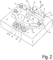
- the FIG. 2 is an associated perspective view showing the below explained components heat sink, primary headlight optics, board unit and fixing.
- the FIG. 3 is a top view of the in the FIG. 2 shown components.
- the Indian FIG. 1 shown section AA is in the FIG. 3 marked by a cut line.
- the sight of the FIG. 3 is in the FIG. 1 characterized by the section line BB.
- the figures do not correspond in every detail.
- the headlamp system 1 has a board unit 2.
- the circuit board unit 2 comprises a circuit board 5 and a light source 4 arranged on the circuit board 5, which is configured as an LED (light emitting diode).
- the circuit board 5 has a circuit for supplying the LED with operating current. Furthermore, the circuit is configured to process input signals by means of which the LED can be controlled. Via a connector 49, the circuit board 5 with a controller and / or a power supply (not shown in the figures) connectable.
- the headlamp system 1 has a primary headlamp optics 12 to focus headlight, which was emitted from the light source 4, and to direct to a secondary headlamp optics 8.
- the primary headlamp optics 12, which focuses the headlamp light of the light source 4 has the reflectors 6, 7, 50 and 24 (shown in FIGS Figures 2 and 3 ) on.
- the primary headlight optics 12 additionally or alternatively has one or more refractive optical elements, such as lenses.
- the secondary headlight optics 8 is configured as a projection lens. Due to the secondary headlight optics 8, the headlight light leaves the headlight system 1.
- the secondary headlight optics 8 can therefore be referred to as light exit headlight optics.
- the secondary headlight optics additionally or alternatively has one or more reflective optical elements, such as mirrors.
- a surface of the board unit 2 which is remote from the light source 4 (such as a surface of the back of the board 5) in surface contact with a thermal contact surface 10 of a heat sink 3.
- the heat contact surface 10 is in a plane arranged.
- the thermal contact surface 10 therefore prevents movements of the board unit 2 which are not parallel to the plane of the thermal contact surface 10. Therefore, in the guided movement, the board unit 2 is moved in a direction parallel to the board main plane PE (shown in FIG FIG. 1 ) of the board 5 out.
- the guided motion may be substantially perpendicular to a direction of a light beam 38 (shown in FIG FIG. 1 ) of the headlight light, the direction of a The position at which the light beam exits the primary headlight optics 12 is measured.
- the primary headlamp optics 12 During the guided movement, the primary headlamp optics 12 remain in fixed position and orientation relative to the board unit 2. Therefore, the primary headlamp optics 12 may be referred to as movable headlamp optics 12.
- the primary headlamp optics 12 may be fixed relative to the board unit 2 for all directions parallel to the board main plane PE .
- this can be done by projections of the primary headlight optics 12, which engage in corresponding recesses of the board unit 2.
- the fixing of the primary headlight optics 12 relative to the board unit 2 can be effected by the pressing force of the fixing element 11.
- the primary headlight optics 12 firmly connected to the board unit 2, for example glued, is.
- the headlight system 1 of the first embodiment provides an adjustability in which the light source 4 and the primary headlamp optical system 12 are adjustable in position relative to the secondary headlamp optical system 8 together.
- the holder of the secondary headlight optics 8 in the headlamp system 1 is configured so that the position and / or orientation of the secondary headlamp optics 8 is independent of the joint guided movement of the board unit 2 and the primary headlamp optics 12 adjustable.
- the board unit 2 is guided by further guide elements with respect to the heat sink 3, which restricts the guided movement of the board unit 2 within the guide plane, which is defined by the thermal contact surface 10, to a linear guideway 22.
- These guide elements are in the FIGS. 1 to 3 Not shown.
- the board unit 2 for example, at least two elongated recesses, such as slots.
- the elongated recesses extend parallel to the guide track 22.
- the heat sink 3 has at least two projections, which also in the FIGS. 1 to 3 are not shown. Each of the projections of the heat sink 3 engages in one of the elongate recesses of the board unit 2.
- the headlamp system 1 has a fixing element 11, which is configured in the embodiment shown as a leaf spring, which is formed from flat material.
- the fixing element 11 is designed so that during the guided movement, the board unit 2 is pressed against the thermal contact surface 10 of the heat sink 3.
- the fixing element 11 is fixed by means of fixing screws 13, 14 and 15 to the heat sink 3 (ie, in particular fastened), whereby the fixing element 11 is supported on the heat sink 3.
- the fixing element 11 also has three spring arms 16, 17 and 18, which engage at three points on the primary headlight optics 12.
- the pressing force, which is generated by the fixing element 11, is transmitted to the board unit 2 via the primary headlight optics 12. As a result, the board unit 2 is pressed against the thermal contact surface 10.
- the headlamp system 1 may have additional fixing means for fixing the board unit 2 in a set position. For example, an additional fixation can be done by clamping or adhesive.
- the headlamp system 1 has a board actuator 19, which is configured as a set screw in the embodiment shown.
- the adjusting screw is arranged in a threaded bushing 20, which has a counter-screw corresponding to the adjusting screw.
- the screw is a self-tapping screw.
- a force application angle ⁇ of the attack of the board actuator 19 on the board unit 2 is greater than zero.
- the force application angle is an angle between a direction vector of a feed movement of the board actuator 19 (for example, in FIG Direction of the force application point P as shown by the arrow 21) and a direction vector of the motion of the board unit 2 generated thereby (as shown by the arrow 48).
- the force application angle ⁇ which is greater than zero, a translation between the advancing movement of the board actuator 19 and the guided movement of the board unit 2 can be effected. This allows a precise adjustment of the headlamp system.
- the force application angle ⁇ is greater than or equal to 95 degrees. This allows a space-saving arrangement of the board actuator 19 on one side of the board unit 2, which is remote from the light source 4.
- the force application point P at which the board actuator 19 acts on the board unit 2, is located on an attack surface A, which is angled relative to the board main plane PE .
- the attack surface A is a surface of an angled portion 25 of the board 5.
- the angle ( ⁇ ) of the bend is greater than 60 degrees and less than 80 degrees.
- attack surface A is a surface of the primary headlight optics 12.
- the force application point P moves along the attack surface A.
- the headlamp system 1 has a board reset component 23 which is configured to generate a counterforce to the actuating force of the board actuator 19. Due to the counterforce, the board unit 2 is pressed against the board actuator 19.
- the board reset component 23 is configured as a spring arm of a leaf spring, which at a force application point Q at a projection 46 of the primary headlight optics 12 attacks.
- the spring arm of the board reset component 23 acts on the board unit 2.
- a free end portion of the spring arm is supported on a projection 31 which protrudes from the heat sink 3 and is rigidly connected thereto or formed integrally with the heat sink 3.
- the thermally conductive contact between the board unit 2 and the thermal contact surface 10 may be in particular a contiguous contact.
- a surface of the board 5 may be in contiguous contact with the thermal contact surface 10 (particularly with a surface of the heat sink).
- a low friction for the guided movement of the board unit 2 relative to the heat sink 3 and a high thermal conductivity for the heat transfer from the board 5 to the heat sink 3 can be obtained if the adjoining surfaces of the heat transfer in each case a high flatness and / or a low roughness respectively.
- the pressing force of the fixing element 11 can be increased without impairing the function of the board reset component 23.
- a smaller force of the board actuator 19 is sufficient to move the board unit 2.
- the force of the sinker actuator 19 on the angled attack surface A then counteracts to a lesser extent the pressing force of the fixing element 11.
- the heat-conducting contact via a lubricating medium, which is arranged between a surface of the board unit 2 and the thermal contact surface 10.
- the lubricating medium may be configured to reduce the friction between the surface of the board unit 2 and the thermal contact surface 10.
- the heat-conductive contact between the board unit 2 and the thermal contact surface 10 is at least partially not adjacent to each other.
- the heat-conducting contact can be made at least partially by means of a heat-conducting medium.
- the heat transfer medium can act as a lubricant.
- the heat conducting means may comprise, for example, a thermal compound and / or a heat conducting foil.
- the heat conducting agent may be configured to be insulating. Thereby, a configuration is conceivable in which a galvanic separation between the board 5 and the heat sink 3 by means of the heat-conducting takes place.
- the heat-conducting agent may comprise, for example, silicone oil and / or zinc oxide.
- a thermal conductivity of the heat-conducting medium can have a value between 0.1 W / (m.K) and 30 W / (m.K), in particular a value between 0.3 W / (m.K) and 20 W / (m.K) ) respectively.
- an increased heat conductivity for the heat transfer can further by the arrangement of the force application points for the board actuator 19 (force application point P in the FIGS. 1 to 3 ), as well as for the board reset component 23 (force application point Q).
- the force application point Q on which the board return component 23 engages and the point of application of force P on which the board actuator 19 engages define a straight line 53 (shown in FIG FIG. 3 ) on which both force application points P and Q are arranged.
- the headlight system 1 is designed such that in this projection the straight line 53 has an angle ⁇ to the guide track 22 which is less than 20 degrees, less than 10 degrees, or less than 5 degrees.
- the straight line 53 can be aligned along the guideway 22.
- the force application points P and Q may be arranged opposite or substantially opposite one another relative to the light source 4.
- the board reset component 23 is integrally formed with the fixing element 11. This facilitates the assembly, since the fixing element 11 and the board reset component 23 can be mounted together by means of the fixing screws 13, 14 and 15.
- the one-piece component has a first portion and a second portion.
- the first portion includes the spring arms 16, 17 and 18 while the second portion provides the spring arm of the board return component 23.
- the sections are angled relative to each other.
- the spring arms 16, 17 and 18 of the fixing element 11 and the board return component 23 and the surfaces of the primary headlight optics 12 are configured so that the force application region, via which the spring force of the respective spring arm is transmitted, is spaced from an edge of the spring arm.
- the area of the primary headlight optics 12, on which the fixing element 11 or the board return component 23 engages is protected from contact with a ridge of the spring arm, which may be present at the edge of the spring arm due to the production.
- contact of the burr with the primary headlamp optics 12 is disadvantageous because it damages the primary headlamp optics 12 and / or increases the friction for the guided movement of the board unit 2.
- increased friction may cause a feed of the board actuator 19 (shown in FIG FIG. 1 ) to the force application point P causes the board 5 does not move as intended, but too much of the thermal contact surface 10th is pushed away, so that the effectiveness of the heat dissipation is impaired.
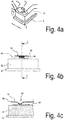
- FIGS. 4a to 4c illustrate how, for example, the spring arm 16 of the fixing element 11 engages the primary headlight optics 12.
- the FIG. 4a is a section of the perspective view of FIG. 2
- the FIG. 4b shows the spring arm 16 and a portion of the primary headlamp optics 12 and the board 5, seen along an axis of the spring arm 16.
- Die FIG. 4b shows a cross section along the section line CC, which in the FIG. 4b is shown.
- the primary headlight optics 12 has a projection 40 on which the spring arm 16 engages in an area where it has a bend 45 (shown in FIG Figure 4c ) having.
- the projection 40 causes the lateral ends 42, 43 of the spring arm 16 in the region of the bend 45 does not come into contact with the surface of the primary headlight optics 12.
- a distal end 44 of the spring arm 16 does not come into contact with the surface of the primary headlamp system 12.
- the projection 40 has an elongate shape and extends substantially parallel to the guide track 22 (shown in FIG. 2 ).
- An axis of the profile of the bend 45 of the spring arm 16 extends substantially perpendicular to the axis of the projection 40.
- the force application points in the spring arms 17 and 18 are designed accordingly.
- the board reset component 23 attacks the board reset component 23 on the projection 46 of the primary headlight optics 12.
- the board reset component 23 has a bend through which an edge 47 of the return component of the primary Headlamp optics 12 is spaced. The opposite edge protrudes beyond an edge of the primary headlight optics 12.
- the spring arms are designed so that for each of the spring arms, an edge of the respective spring arm is spaced from a surface region of the spring arm, via which the spring force of the spring arm is transmitted.
- FIG. 5 shows components of a headlamp system 1a according to a second embodiment.
- the headlamp system 1 a has components that belong to components of the headlight system 1 of the first embodiment (shown in FIGS FIGS. 1 to 4 ) are analog. Therefore, these components are provided with similar reference numerals but having the a sign a .
- the headlamp system 1a of the second embodiment is configured such that the board unit 2a is movable in a plane parallel to the heat contact surface of the heat sink 3a in two dimensions. As in the headlamp system 1 of the first embodiment, the board unit 2a is thereby pressed against the thermal contact surface with the aid of a fixing element 11a.
- the spring arms 16a, 17a, and 18a engage the primary headlight optics 12a.
- the primary headlamp optics 12a no reflectors, but an auxiliary lens 35a.
- the headlight system 1a has a guide element 24a, of which in the FIG. 5 two sections can be seen, which protrude on both sides under the fixing element 11a.
- the board unit 2a is mounted on the guide element 24a one-dimensionally movable accordingly a first axis 29a. It is also conceivable that additionally or alternatively, the primary headlight optics 12a is mounted on the guide element 24a in a one-dimensionally movable manner.
- the guide member 24a is mounted on the heat sink 3a one-dimensionally movable according to a second axis 30a.
- the heat sink 3a on the guide grooves 51a and 26a.
- the guide grooves 51a and 26a serve to guide two guide pins 27a and 28a which are formed on the guide member 24a and which are oriented along the second axis 30a.
- the guide of the board unit 2a on the guide member 24a is carried out in a similar manner as in the first embodiment, the leadership of the board unit 2 (shown in the FIG. 1 ) by the heat sink 3.
- the guide member 24a has projections (not shown), which engage in corresponding recesses of the board 5a.
- the guidance of the board unit 2a on the guide element 24a, as well as the guidance of the guide element 24a on the heat sink 3a represents a cross guide for movements parallel to the plane of the thermal contact surface, which provides the two-dimensional guidance of the board unit 2a relative to the heat sink 3a.
- the headlight system 1a For adjusting the position of the board unit 2a along the first axis 29a of the two-dimensional guide, the headlight system 1a comprises a board actuator (not shown in FIGS FIG. 5 ) which engages an angled portion 25a of the board 5a.
- the board actuator of the headlamp system 1a of the second embodiment is formed as a set screw, which is arranged in a threaded bushing 20a.
- a board reset component 23a which is designed as a spring arm.
- the board reset component 23a is integrally formed with the fixing member 11a.
- the headlamp system 1a on a guide element actuator 55a which is formed in an analogous manner as the board actuator.
- the guide member actuator 55a hidden by the guide member 24a and indicated schematically by a circle.
- the headlight system 1a has a guide element restoring component 32a, which is designed as a spring arm.
- the guide member return component 32a is formed integrally with the fixing member 11a.
- a free end portion of the spring arm of the guide member return component 32a is supported on a projection 34a which protrudes from and is rigidly connected to the heat sink 3a or integrally formed with the heat sink 3a.
- the one-piece design of the board reset component 23a and the guide element return component 32a with the fixing element 11a causes a simplification of the assembly, since all three components can be mounted simultaneously by fixing with the fixing screws 13a - 15a, 33a and 52a.
- the Guide element return component 32a and / or the board return component 23a is formed separately from the fixing element 11a.
- Seen in a direction perpendicular to the guide plane extends between the guide pins 27a and 28a, the guide member 24a between the board unit 2a and the primary headlight optics 12a, and / or between the primary headlight optics 12a and the fixing member 11a.
- the guide element 24a extends between the board unit 2a and the heat sink 3a.
- thermal contact between the board unit 2a and the heat sink 3a is thereby reduced.
- improved heat transfer between the board 5a and the heat sink 3a can be obtained by the arrangement of the force application points for the board actuator 19a (force application point P in FIG FIG. 5 ), for the board return component 23a (force application point Q ), for the guide element actuator 55a (force application point R) and / or for the guide element return component 32a (force application point S).
- a projection plane Projected onto a projection plane, which runs parallel to the thermal contact surface 10 and which therefore in the FIG. 5 oriented parallel to the paper plane, define the point of application Q , at which the board return component 23a attacks, as well as the force application point P , at which the board actuator 19a attacks, a common straight line 53a, on which both force application points P, Q are arranged.
- the orientation of the straight line 53a is not always exactly aligned along the first axis 29a, but depends on the Position of the guide member 24 relative to the heat sink 3 along the second axis 30 a from.
- the headlamp system 1a is formed so that in this projection, an angle ⁇ between the straight line 53a and the first axis 29a remains low.
- the angle ⁇ is less than 20 degrees or less than 10 degrees or less than 5 degrees.
- the force application points P and Q may be arranged opposite or substantially opposite one another relative to the light source 4a.
- the force application point S at which the guide element return component 32a engages to generate the counterforce to the actuating force of the guide element actuator 55a (in particular on the projection 37a of the guide element 24) and the force application point R , on which the guide element actuator 55a engages a common straight line 54a, on which both force application points R, S are arranged.
- the headlight system can be designed such that in this projection the angle ⁇ (shown in FIG. 5 ) between the straight line 54a and the second axis 30a is less than 20 degrees, less than 10 degrees, or less than 5 degrees.
- the straight line 54a may be aligned along the second axis.
- the force application points R and S may be arranged opposite or substantially opposite one another relative to the light source 4a.
- the primary headlight optics 12, 12a and the board 5, 5a respectively protected by the fixing element 11, 11a from light, which incident through the secondary headlight optics 8, 8a from the outside to the primary headlight optics 12, 12a and on the board 5,5a ,
- this incidence of light leads to focused light spots on the primary headlamp optics 12, 12a, which reduce the life of the primary headlamp optics 12, 12a and components of the board 5, 5a.
- a headlight system 1, 1a which provides an adjustability of the board unit 2, 2a and the primary headlight optics 12, 12a, while at the same time provides protection for the primary headlight optics 12, 12a from external light.
Landscapes
- Engineering & Computer Science (AREA)
- General Engineering & Computer Science (AREA)
- Non-Portable Lighting Devices Or Systems Thereof (AREA)
- Arrangement Of Elements, Cooling, Sealing, Or The Like Of Lighting Devices (AREA)
- Lighting Device Outwards From Vehicle And Optical Signal (AREA)
Abstract
Description
- Die Erfindung bezieht sich auf ein justierbares Scheinwerfersystem für Kraftfahrzeuge. Insbesondere bezieht sich die vorliegende Erfindung auf ein Scheinwerfersystem mit einer positionsjustierbaren LED (light emitting diode)-Lichtquelle.
- Bei Kraftfahrzeugen werden zunehmend Scheinwerfer eingesetzt, welche eine LED-Lichtquelle anstelle einer Halogen-Lichtquelle oder einer Xenon-Lichtquelle aufweisen. Für den Einsatz von LED-Lichtquellen sprechen insbesondere die längere Haltbarkeit, der geringere Energieverbrauch und die hohe mechanische Robustheit. LED-Lichtquellen können für unterschiedliche Lichtfarben konfiguriert sein und die Lichtfarbe weißer LED-Lichtquellen ist ähnlich zum Tageslicht. Ein Scheinwerfer kann ein Array von LED-Modulen aufweisen, wobei jedes LED-Modul eine LED-Lichtquelle und eine Optik aufweist. Beispielsweise kann das Scheinwerfersystem so ausgebildet sein, dass das Abblendlicht nicht lediglich durch eine LED-Lichtquelle bereitgestellt wird, sondern durch zwei oder mehrere LED-Module. Durch die Ansteuerung eines solchen Arrays aus LED-Modulen ist es möglich, die Lichtverteilung des Scheinwerfers variabel einzustellen. Dadurch kann der Scheinwerfer beispielsweise an eine veränderte Verkehrssituation angepasst werden, um ein Lichtassistenzsystem zu realisieren.
- Ein Problem beim Einsatz von LED-Lichtquellen ist, dass möglichst eine Kühlung vorgesehen sein muss, um die Effizienz und die Lebensdauer der LED-Lichtquelle nicht zu verringern. Die Kühlung muss zusätzlich zur Elektronik vorgesehen sein, welche zur Ansteuerung der LED-Lichtquelle erforderlich ist. Dabei wurde bisher davon ausgegangen, dass die Platine, auf welcher die LED-Lichtquelle angeordnet ist, starr mit dem Kühlkörper befestigt sein muss, um die erforderliche Kühlleistung zu erreichen. Sowohl die Kühlung, als auch die Elektronik beschränken nicht nur den vorhandenen Platz, sondern erschweren auch die Realisierung eines justierbaren Scheinwerfersystems.
- Es hat sich aber gezeigt, dass die Justierbarkeit eines Scheinwerfersystems eine große Bedeutung hat. Generell haben sich justierbare Scheinwerfersysteme lichttechnisch als effizienter erwiesen und können dadurch eine höhere Leistung bereitstellen. Durch die Justierbarkeit ist es insbesondere möglich, Bauteil- und Fügetoleranzen auszugleichen.
- Bedeutend sind justierbare Scheinwerfersysteme dabei insbesondere für solche Scheinwerfersysteme, welche eine Primäroptik und eine Sekundäroptik aufweisen, welche nacheinander im Strahlengang des Scheinwerferlichts angeordnet sind. Die Position der Primäroptik relativ zur Sekundäroptik kann die Helldunkelgrenze sowie die Qualität und Lichtstärke der Lichtverteilung beeinflussen.
- Bedeutend ist die Justierbarkeit ferner für Scheinwerfersysteme, bei welchen eine Lichtfunktion mit Hilfe eines Arrays aus LED-Modulen bereitstellt wird. Für solche Scheinwerfer hat es sich gezeigt, dass eine Justierbarkeit der LED-Module relativ zueinander vorteilhaft ist. Aus Platzgründen sollten hierbei die einzelnen LED-Module möglichst klein ausgeführt werden. Durch die kleine Baugröße wird jedoch auch die Lichtcharakteristik toleranzempfindlicher.
- Es besteht daher ein Bedarf an einem justierbaren Scheinwerfersystem, insbesondere an einem Scheinwerfersystem mit einer LED-Lichtquelle, welches eine präzise Justierbarkeit bei geringem Platzbedarf bereitstellt.
- Durch die vorliegende Offenbarung wird insbesondere aufgezeigt, dass eine geführte Bewegung der Platine, auf welcher die Lichtquelle angeordnet ist, relativ zu einer Wärmesenke mit Hilfe eines Fixierelements realisiert werden kann, welches bei der geführten Bewegung die Platine gegen die Wärmesenke drückt.
- Entsprechend stellen Ausführungsformen ein justierbares Scheinwerfersystem für eine Fahrzeugaußenbeleuchtung bereit. Das Scheinwerfersystem kann eine Platineneinheit aufweisen. Die Platineneinheit kann eine Platine und eine Lichtquelle aufweisen. Die Lichtquelle kann auf der Platine angeordnet sein. Die Lichtquelle kann zur Erzeugung von Scheinwerferlicht konfiguriert sein. Das Scheinwerfersystem kann eine Wärmesenke aufweisen. Die Wärmesenke kann eine Wärmekontakt-Oberfläche aufweisen. Die Platineneinheit kann mit der Wärmekontakt-Oberfläche in Kontakt, das heißt insbesondere aneinandergrenzend, sein. Das Scheinwerfersystem kann konfiguriert sein zu einer geführten Bewegung der Platineneinheit relativ zur Wärmesenke. Die geführte Bewegung kann mittels der Wärmekontakt-Oberfläche geführt sein. Das Scheinwerfersystem kann ein Fixierelement aufweisen. Das Fixierelement kann so konfiguriert sein, dass es bei der geführten Bewegung die Platineneinheit gegen die Wärmekontakt-Oberfläche drückt.
- Es hat sich gezeigt, dass dadurch ein effizientes Scheinwerfersystem bereitgestellt werden kann, durch welches es möglich ist, Bauteil- und Fügetoleranzen des Scheinwerfersystems auszugleichen. Zusätzlich ist es denkbar, dass mit Hilfe der geführten Bewegung eine Justage der Lichtverteilung im Straßenraum, wie der vertikalen Hell-Dunkel-Grenze, vorgenommen wird.
- Die Lichtquelle kann als LED (light emitting diode) konfiguriert sein. Die LED kann auf der Platine angeordnet sein. Die Platine kann zumindest einen Teil einer Schaltung zur Ansteuerung der LEDs und/oder zumindest einen Teil einer Schaltung zur Stromversorgung der LED aufweisen. Es ist jedoch auch denkbar, dass zumindest ein Teil dieser Funktionen auf einer oder mehreren Platinen integriert ist, welche separat von der Platineneinheit angeordnet sind. Die Platine kann zumindest teilweise als Metallkernplatine, insbesondere als Aluminiumkernplatine, ausgebildet sein. Es ist jedoch auch denkbar, dass die Platine zumindest teilweise als Epoxidharzplatine oder als Keramikplatine konfiguriert ist. Die Wärmekontakt-Oberfläche kann in einer Ebene angeordnet sein. Die Wärmekontakt-Oberfläche kann parallel oder im Wesentlichen parallel zu einer Hauptebene der Platine verlaufen. Der Kontakt zwischen der Wärmekontakt-Oberfläche und der Platineneinheit kann flächig sein. Die geführte Bewegung kann parallel oder im Wesentlichen parallel zu einer Platinen-Hauptebene der Platine erfolgen.
- Der Scheinwerfer kann so konfiguriert sein, dass die Platineneinheit mittels der Wärmekontakt-Oberfläche eindimensional oder zweidimensional geführt bewegbar ist. Das Fixierelement kann die Platineneinheit relativ zur Wärmesenke in einer Richtung senkrecht zur Ebene der Wärmekontakt-Oberfläche fixieren.
- Eines oder mehrere optische Elemente für Scheinwerferlicht, welches von der Lichtquelle emittiert wird, können mit der Platine fest verbunden sein. Diese Komponenten können Teil der Platineneinheit sein. Optische Elemente können beispielsweise Linsen, Spiegel oder Blenden sein. Die Spiegel können Planspiegel, konkave Spiegel oder konvexe Spiegel sein.
- Gemäß einer Ausführungsform ist eine Oberfläche einer Seite der Platineneinheit, welche von der Lichtquelle abgewandt ist, mit der Wärmekontakt-Oberfläche in wärmeleitendem Kontakt, d.h. insbesondere aneinandergrenzend.
- Gemäß einer Ausführungsform erfolgt der wärmeleitende Kontakt zumindest teilweise mit Hilfe eines Wärmeleitmittels des Scheinwerfersystems. Das Wärmeleitmittel kann beispielsweise eine Wärmeleitpaste und/oder eine Wärmeleitfolie aufweisen. Das Wärmeleitmittel kann elektrisch leitfähig oder isolierend sein.
- Beispielsweise kann das Wärmeleitmittel zwischen einer Oberfläche der Platineneinheit und der Wärmekontakt-Oberfläche angeordnet sein. Dadurch kann der wärmeleitende Kontakt zwischen der Platineneinheit und der Wärmekontakt-Oberfläche nicht aneinandergrenzend, sondern über das Wärmeleitmittel erfolgen.
- Zusätzlich oder alternativ kann das Wärmeleitmittel Teil der Wärmesenke sein und insbesondere die Wärmekontakt-Oberfläche der Wärmesenke bilden. Zusätzlich oder alternativ kann das Wärmeleitmittel Teil der Platineneinheit sein und in wärmeleitendem Kontakt, insbesondere angrenzendem wärmeleitenden Kontakt, mit der Wärmekontakt-Oberfläche der Wärmesenke sein.
- Die Wärmesenke kann einen Kühlkörper aufweisen. Die Wärmesenke kann während der geführten Bewegung der Platineneinheit ortsfest sein. Die Wärmesenke kann Teil eines aktiven oder passiven Kühlsystems des Scheinwerfersystems sein.
- Gemäß einer weiteren Ausführungsform ist das Fixierelement als elastisches Fixierelement konfiguriert. Das Fixierelement kann eine Biegefeder, insbesondere eine Blattfeder, aufweisen. Die Blattfeder kann einen oder mehrere Federarme aufweisen. Die Biegefeder kann an der Wärmesenke festgelegt (insbesondere befestigt) sein.
- Gemäß einer weiteren Ausführungsform weist das Scheinwerfersystem eine bewegbare Scheinwerferoptik auf, welche in einem Strahlengang des Scheinwerferlichts angeordnet ist. Der Strahlengang kann als die Summe aller Lichtstrahlen definiert werden, welche von der Lichtquelle ausgehen und welche die Fahrzeugaußenbeleuchtung bilden. Das Scheinwerfersystem kann so konfiguriert sein, dass durch die geführte Bewegung die Platineneinheit und die bewegbare Scheinwerferoptik eine gemeinsame Bewegung ausführen. In anderen Worten kann während der Bewegung die bewegbare Scheinwerferoptik stationär relativ zur Platineneinheit sein. Die geführte Bewegung kann senkrecht oder im Wesentlichen senkrecht zu einer Richtung eines Lichtstrahls des Strahlengangs erfolgen, wobei die Richtung an einer Stelle gemessen wird, an welcher der Lichtstrahl aus der bewegbaren Scheinwerferoptik austritt.
- Die bewegbare Scheinwerferoptik kann eines oder mehrere optische Elemente aufweisen. Die optischen Elemente können als transmissive und/oder als reflektive optische Elemente konfiguriert sein. Die bewegbare Scheinwerferoptik kann eine Kollektoroptik und/oder eine Kollimationsoptik aufweisen.
- Gemäß einer weiteren Ausführungsform ist das Fixierelement ausgebildet, bei der geführten Bewegung eine Kraft zu erzeugen, mittels welcher die bewegbare Scheinwerferoptik relativ zur Platineneinheit fixiert wird. Das Fixierelement kann die bewegbare Scheinwerferoptik gegen die Platineneinheit drücken. Es ist aber auch denkbar, dass die bewegbare Scheinwerferoptik, unabhängig von der Kraft des Fixierelements, fest mit der Platineneinheit verbunden ist, beispielsweise durch eine Klebung. Die bewegbare Scheinwerferoptik kann eine Kraft zum Andrücken der Platineneinheit gegen die Wärmekontakt-Oberfläche über die bewegbare Scheinwerferoptik übertragen.
- Gemäß einer weiteren Ausführungsform weist das Scheinwerfersystem eine Lichtaustritts-Scheinwerferoptik auf, welche im Strahlengang des Scheinwerferlichts angeordnet ist. Die Lichtaustritts-Scheinwerferoptik kann stromabwärts der bewegbaren Scheinwerferoptik angeordnet sein. In anderen Worten kann die Lichtaustritts-Scheinwerferoptik, im Lichtweg des Scheinwerferlichts, nachgeordnet zur bewegbaren Scheinwerferoptik angeordnet sein. Das Scheinwerfersystem kann so ausgebildet sein, dass das Scheinwerferlicht das Scheinwerfersystem durch die Lichtaustritts-Scheinwerferoptik verlässt. Das Scheinwerfersystem kann so konfiguriert sein, dass die Lichtaustritts-Scheinwerferoptik während der geführten Bewegung stationär relativ zur Wärmesenke ist.
- Die Lichtaustritts-Scheinwerferoptik kann ein oder mehrere optische Elemente aufweisen. Die optischen Elemente können als transmissive und/oder als reflektive optische Elemente konfiguriert sein.
- Gemäß einer weiteren Ausführungsform weist das Scheinwerfersystem ein Platinen-Stellglied, insbesondere eine Stellschraube, auf. Das Platinen-Stellglied kann zur Einstellung einer Position der Platineneinheit durch die geführte Bewegung konfiguriert sein. Ein Kraftangriffswinkel zwischen einer Richtung einer Vorschubbewegung des Platinen-Stellgliedes und einer dadurch erzeugten Richtung der geführten Bewegung der Platineneinheit kann größer sein als 20 Grad, oder größer sein als 40 Grad, oder größer sein als 60 Grad, oder größer sein als 90 Grad, oder größer oder gleich sein als 95 Grad. Der Kraftangriffswinkel kann geringer sein als 140 Grad. Der Kraftangriffswinkel kann so gemessen sein, dass er null ist, wenn die Vorschubrichtung des Platinen-Stellgliedes und die dadurch erzeugte Bewegungsrichtung der Platineneinheit parallel und in gleicher Richtung orientiert sind.
- Das Platinen-Stellglied kann in der Wärmesenke lagernd aufgenommen sein. Als Lager hierfür kann beispielsweise eine Gewindebuchse fungieren, welche mit der Wärmesenke verbunden ist und in welcher das Platinen-Stellglied gelagert ist.
- Das Platinen-Stellglied kann beispielsweise an der Platineneinheit, insbesondere an der Platine, und/oder an der bewegbaren Scheinwerferoptik angreifen. Das Platinen-Stellglied kann an einer Angriffsoberfläche angreifen, welche von der Lichtquelle abgewandt ist. Die Angriffsoberfläche kann abgewinkelt zur Ebene der Wärmekontakt-Oberfläche und/oder abgewinkelt zur Platinen-Hauptebene sein. Ein Winkel der Abwinkelung kann größer sein als 20 Grad, oder größer sein als 30 Grad, oder größer sein als 40 Grad, oder größer sein als 50 Grad. Der Winkel der Abwinkelung kann geringer sein als 90 Grad, geringer sein als 80 Grad, oder geringer sein als 70 Grad. Der Winkel der Abwinkelung kann über einem Bereich außerhalb der Platineneinheit gemessen sein. In anderen Worten kann der Winkel der Abwinkelung so gemessen sein, dass er sich nicht durch die Platineneinheit erstreckt.
- Das Platinen-Stellglied kann einen Abschnitt aufweisen, welcher im Bereich des Kraftangriffspunktes konisch zuläuft. Bei einer Stellbewegung des Platinen-Stellgliedes kann das Platinen-Stellglied eine Rotationsbewegung um eine Vorschubachse des Platinen-Stellgliedes ausführen. Das Platinen-Stellglied kann ein Vorschubgewinde aufweisen, welches eine Rotation des Platinen-Stellgliedes in eine Vorschubbewegung umsetzt.
- Gemäß einer weiteren Ausführungsform verschiebt sich ein Kraftangriffspunkt des Platinen-Stellgliedes an der Angriffsoberfläche entsprechend der geführten Bewegung der Platineneinheit. Für jeden der verschiedenen Kraftangriffspunkte kann der Kraftangriffswinkel gleich oder im Wesentlichen gleich sein.
- Gemäß einer weiteren Ausführungsform weist das Scheinwerfersystem eine Platinen-Rückstellkomponente auf. Die Platinen-Rückstellkomponente kann konfiguriert sein, eine Rückstellkraft zu einer Stellkraft des Platinen-Stellgliedes zu erzeugen. Die Platinen-Rückstellkomponente kann mit dem Fixierelement einstückig ausgebildet sein. Die einstückige Komponente kann zwei Abschnitte aufweisen, welche relativ zueinander abgewinkelt sind. Ein erster der zwei Abschnitte kann zumindest ein Teil des Fixierelements sein und der zweite Abschnitt kann zumindest ein Teil der Platinen-Rückstellkomponente sein. Jeder der Abschnitte kann einen Federarm einer Biegefeder aufweisen.
- Gemäß einer weiteren Ausführungsform ist die Platineneinheit zweidimensional geführt bewegbar. Das Scheinwerfersystem kann ein Führungselement aufweisen. Das Scheinwerfersystem kann so konfiguriert sein, dass die Platineneinheit relativ zum Führungselement in Richtung einer ersten Achse der zweidimensionalen Führung geführt ist. Alternativ oder zusätzlich kann das Scheinwerfersystem so konfiguriert sein, dass das Führungselement relativ zur Wärmesenke in Richtung einer zweiten Achse der zweidimensionalen Führung geführt ist. Das Scheinwerfersystem kann eine Kreuzführung aufweisen zur Führung der Platineneinheit relativ zur Wärmesenke. Die Kreuzführung kann das Führungselement aufweisen.
- Die erste und die zweite Achse können nichtparallel, senkrecht oder im Wesentlichen senkrecht sein. Das Führungselement kann mit der Wärmesenke, mit der Platineneinheit und/oder mit der bewegbaren Scheinwerferoptik führend im Eingriff sein.
- Gemäß einer weiteren Ausführungsform weist das Scheinwerfersystem ein Führungselement-Stellglied auf. Das Führungselement-Stellglied kann konfiguriert sein, am Führungselement anzugreifen. Das Führungselement-Stellglied kann zu einer Einstellung einer Position des Führungselements relativ zur Wärmesenke konfiguriert sein. Das Scheinwerfersystem kann ferner eine Führungselement-Rückstellkomponente aufweisen. Die Führungselement-Rückstellkomponente kann konfiguriert sein, eine Rückstellkraft zu einer Stellkraft des Führungselement-Stellgliedes zu erzeugen. Die Führungselement-Rückstellkomponente kann mit dem Fixierelement einstückig ausgebildet sein. Die einstückige Komponente kann zwei Abschnitte aufweisen, welche relativ zueinander abgewinkelt sind. Ein erster der zwei Abschnitte kann zumindest ein Teil des Fixierelements sein und der zweite Abschnitt kann zumindest ein Teil der Führungselement-Rückstellkomponente sein. Jeder der Abschnitte kann einen Federarm einer Biegefeder aufweisen.
- Gemäß einer weiteren Ausführungsform ist das Fixierelement, die Platinen-Rückstellkomponente und/oder die Führungselement-Rückstellkomponente aus Flachmaterial geformt oder zumindest teilweise als Biegefeder konfiguriert. Die Biegefeder kann eine Blattfeder sein. Die Biegefeder kann an der Wärmesenke festgelegt (insbesondere befestigt) sein. Dadurch kann eine Abstützung der Biegefeder an der Wärmesenke bewirkt werden.
- Gemäß einer weiteren Ausführungsform weist das Fixierelement, die Platinen-Rückstellkomponente und/oder die Führungselement-Rückstellkomponente jeweils einen Federarm einer Blattfeder auf. Das Scheinwerfersystem kann so ausgebildet sein, dass ein Rand des Federarmes beabstandet ist von einem Oberflächenbereich des Federarmes, über welchen eine Federkraft des Federarmes übertragen wird.
- Gemäß einer weiteren Ausführungsform definiert in einer Projektion auf eine Projektionsebene, welche parallel zur Wärmekontakt-Oberfläche verläuft, ein Kraftangriffspunkt, an welchem das Platinen-Stellglied angreift, sowie ein Kraftangriffspunkt, an welchem die Platinen-Rückstellkomponente angreift, eine gemeinsame Gerade, auf welcher beide Kraftangriffspunkte angeordnet sind.
- In dieser Projektion kann die Gerade einen Winkel zu einer Führungsbahn einer eindimensionalen Führung oder zu einer Achse einer zweidimensionalen Führung bilden. Mit Hilfe der Führung kann die geführte Bewegung der Platineneinheit relativ zur Wärmesenke bewirkt sein.
- Der Winkel kann geringer als 20 Grad oder geringer als 10 Grad oder geringer als 5 Grad sein. Insbesondere kann die Gerade entlang der Achse oder entlang der Führungsbahn ausgerichtet sein.
- Zusätzlich oder alternativ können in dieser Projektion die Kraftangriffspunkte gegenüberliegend oder im Wesentlichen gegenüberliegend relativ zur Lichtquelle angeordnet sein.
- Ausführungsbeispiele der vorliegenden Erfindung werden mit Bezug auf die beiliegenden Figuren erläutert.
- Figur 1
- zeigt einen Schnitt durch ein Scheinwerfersystem gemäß einem ersten Ausführungsbeispiel;
- Figur 2
- zeigt eine perspektivische Ansicht auf die Wärmesenke, die Platineneinheit, die primäre Scheinwerferoptik und auf das Fixierelement des in der
Figur 1 gezeigten Scheinwerfersystems; - Figur 3
- zeigt eine Draufsicht auf die Komponenten, welche in der
Figur 2 dargestellt sind; - Figuren 4a bis 4c
- illustrieren den Kraftangriffspunkt zwischen einem Federarm des Fixierelements und der primären Scheinwerferoptik im Scheinwerfersystem, welches in der
Figur 1 gezeigt ist; und - Figur 5
- zeigt eine Draufsicht auf die Wärmesenke, die Platineneinheit, die primäre Scheinwerferoptik und auf das Fixierelement eines Scheinwerfersystems gemäß einem zweiten Ausführungsbeispiel.
- Die
Figur 1 zeigt eine Schnittdarstellung eines Scheinwerfersystems 1 gemäß einem ersten Ausführungsbeispiel. DieFigur 2 ist eine dazugehörige perspektivische Ansicht, welche die weiter unten erläuterten Komponenten Wärmesenke, primäre Scheinwerferoptik, Platineneinheit und Fixierelement zeigt. DieFigur 3 ist eine Draufsicht auf die in derFigur 2 gezeigten Komponenten. Der in derFigur 1 gezeigte Schnitt A-A ist in derFigur 3 durch eine Schnittlinie markiert. Die Sichtrichtung derFigur 3 ist in derFigur 1 durch die Schnittlinie B-B gekennzeichnet. Aus Gründen einer vereinfachten Darstellung korrespondieren die Figuren nicht in jedem Detail. - Das Scheinwerfersystem 1 weist eine Platineneinheit 2 auf. Die Platineneinheit 2 umfasst eine Platine 5 und eine auf der Platine 5 angeordnete Lichtquelle 4, welche als LED (light emitting diode) konfiguriert ist. Die Platine 5 weist eine Schaltung auf zur Versorgung der LED mit Betriebsstrom. Des Weiteren ist die Schaltung konfiguriert, Eingangssignale zu verarbeiten, mit Hilfe derer die LED angesteuert werden kann. Über einen Verbinder 49 ist die Platine 5 mit einer Steuerung und/oder einer Stromversorgung (nicht gezeigt in den Figuren) verbindbar.
- Das Scheinwerfersystem 1 weist eine primäre Scheinwerferoptik 12 auf, um Scheinwerferlicht, welches von der Lichtquelle 4 emittiert wurde, zu bündeln und auf eine sekundäre Scheinwerferoptik 8 zu lenken. Die primäre Scheinwerferoptik 12, welche das Scheinwerferlicht der Lichtquelle 4 bündelt, weist die Reflektoren 6, 7, 50 und 24 (gezeigt in den
Figuren 2 und3 ) auf. Es ist aber auch denkbar, dass die primäre Scheinwerferoptik 12 zusätzlich oder alternativ eines oder mehrere refraktive optische Elemente, wie Linsen, aufweist. In dem gezeigten Ausführungsbeispiel ist die sekundäre Scheinwerferoptik 8 als Projektionslinse konfiguriert. Durch die sekundäre Scheinwerferoptik 8 verlässt das Scheinwerferlicht das Scheinwerfersystem 1. Die sekundäre Scheinwerferoptik 8 kann daher als Lichtaustritts-Scheinwerferoptik bezeichnet werden. Es ist denkbar, dass die sekundäre Scheinwerferoptik zusätzlich oder alternativ eines oder mehrere reflektive optische Elemente, wie Spiegel, aufweist. - Im ersten Ausführungsbeispiel, welches in den
Figuren 1 bis 3 dargestellt ist, ist eine Oberfläche der Platineneinheit 2, welche von der Lichtquelle 4 abgewandt ist (wie beispielsweise eine Oberfläche der Rückseite der Platine 5) in flächigem Kontakt mit einer Wärmekontakt-Oberfläche 10 einer Wärmesenke 3. Die Wärmekontakt-Oberfläche 10 ist in einer Ebene angeordnet. Mit Hilfe der Wärmekontakt-Oberfläche 10 wird eine Bewegung der Platineneinheit 2 relativ zur Wärmesenke 3 geführt. Die Wärmekontakt-Oberfläche 10 verhindert daher Bewegungen der Platineneinheit 2, welche nichtparallel sind zur Ebene der Wärmekontakt-Oberfläche 10. Daher wird bei der geführten Bewegung die Platineneinheit 2 in einer Richtung parallel zur Platinen-Hauptebene PE (gezeigt in derFigur 1 ) der Platine 5 geführt. Die geführte Bewegung kann im Wesentlichen senkrecht zu einer Richtung eines Lichtstrahls 38 (gezeigt in derFigur 1 ) des Scheinwerferlichts erfolgen, wobei die Richtung an einer Stelle gemessen wird, an welcher der Lichtstrahl aus der primären Scheinwerferoptik 12 austritt. - Während der geführten Bewegung bleibt die primäre Scheinwerferoptik 12 in fester Position und Orientierung relativ zur Platineneinheit 2. Daher kann die primäre Scheinwerferoptik 12 als bewegbare Scheinwerferoptik 12 bezeichnet werden.
- Die primäre Scheinwerferoptik 12 kann beispielsweise relativ zur Platineneinheit 2 für alle Richtungen parallel zur Platinen-Hauptebene PE fixiert sein. Beispielsweise kann dies durch Vorsprünge der primären Scheinwerferoptik 12 erfolgen, welche in korrespondierende Ausnehmungen der Platineneinheit 2 eingreifen. Für die Richtung senkrecht zur Platinen-Hauptebene PE kann die Fixierung der primären Scheinwerferoptik 12 relativ zur Platineneinheit 2 durch die Andrückkraft des Fixierelements 11 erfolgen. Alternativ ist es auch denkbar, dass die primäre Scheinwerferoptik 12 mit der Platineneinheit 2 fest verbunden, beispielsweise verklebt, ist.
- Folglich stellt das Scheinwerfersystem 1 des ersten Ausführungsbeispiels eine Justierbarkeit bereit, bei welcher die Lichtquelle 4 und die primäre Scheinwerferoptik 12 gemeinsam in ihrer Position relativ zur sekundären Scheinwerferoptik 8 justierbar sind.
- Es ist denkbar, dass die Halterung der sekundären Scheinwerferoptik 8 im Scheinwerfersystem 1 so konfiguriert ist, dass die Position und/oder Orientierung der sekundären Scheinwerferoptik 8 unabhängig von der gemeinsamen geführten Bewegung der Platineneinheit 2 und der primären Scheinwerferoptik 12 justierbar ist.
- Im ersten Ausführungsbeispiel ist die Platineneinheit 2 durch weitere Führungselemente gegenüber der Wärmesenke 3 geführt, welche die geführte Bewegung der Platineneinheit 2 innerhalb der Führungsebene, welche durch die Wärmekontakt-Oberfläche 10 definiert ist, auf eine geradlinige Führungsbahn 22 einschränken. Diese Führungselemente sind in den
Figuren 1 bis 3 nicht gezeigt. - Um solche Führungselemente bereitzustellen, weist die Platineneinheit 2 beispielsweise zumindest zwei langgestreckte Ausnehmungen, wie Langlöcher, auf. Die langgestreckten Ausnehmungen erstrecken sich parallel zur Führungsbahn 22. Die Wärmesenke 3 weist zumindest zwei Vorsprünge auf, welche ebenfalls in den
Figuren 1 bis 3 nicht dargestellt sind. Jeder der Vorsprünge der Wärmesenke 3 greift in eine der langgestreckten Ausnehmungen der Platineneinheit 2 ein. - Das Scheinwerfersystem 1 weist ein Fixierelement 11 auf, welches im gezeigten Ausführungsbeispiel als Blattfeder konfiguriert ist, die aus Flachmaterial geformt ist. Das Fixierelement 11 ist so ausgebildet, dass während der geführten Bewegung die Platineneinheit 2 gegen die Wärmekontakt-Oberfläche 10 der Wärmesenke 3 gedrückt wird. Das Fixierelement 11 ist mit Hilfe von Fixierschrauben 13, 14 und 15 an der Wärmesenke 3 festgelegt (d.h. insbesondere befestigt), wodurch sich das Fixierelement 11 an der Wärmesenke 3 abstützt. Das Fixierelement 11 weist ferner drei Federarme 16, 17 und 18 auf, welche an drei Punkten auf der primären Scheinwerferoptik 12 angreifen. Die Andrückkraft, welche durch das Fixierelement 11 erzeugt wird, wird über die primäre Scheinwerferoptik 12 auf die Platineneinheit 2 übertragen. Dadurch wird die Platineneinheit 2 gegen die Wärmekontakt-Oberfläche 10 gedrückt. Alternativ oder zusätzlich ist es auch denkbar, dass einer oder mehrere der Federarme 16, 17 und 18 an der Platineneinheit 2, insbesondere an der Platine 5, angreifen.
- Durch das Fixierelement 11 werden folglich die Platineneinheit 2 und die primäre Scheinwerferoptik 12 in einer Richtung senkrecht zur Führungsbahn 22 der geführten Bewegung fixiert. Zusätzlich bewirkt die Andrückkraft, welche vom Fixierelement 11 erzeugt wird, dass eine ausreichende Wärmeleitfähigkeit für den Wärmeübergang von der Platine 5 auf die Wärmesenke 3 vorhanden ist. Das Scheinwerfersystem 1 kann zusätzliche Fixiermittel aufweisen, um die Platineneinheit 2 in einer eingestellten Position zu fixieren. Beispielsweise kann eine zusätzliche Fixierung durch Klemmen oder Klebstoff erfolgen.
- Um eine Position der Platineneinheit 2 und der primären Scheinwerferoptik 12 mit Hilfe der geführten Bewegung einzustellen, weist das Scheinwerfersystem 1 ein Platinen-Stellglied 19 auf, welches in dem gezeigten Ausführungsbeispiel als Stellschraube konfiguriert ist. Die Stellschraube ist in einer Gewindebuchse 20 angeordnet, welche ein zur Stellschraube korrespondierendes Gegengewinde aufweist. Es ist aber auch denkbar, dass die Stellschraube eine selbstschneidende Stellschraube ist. Durch eine Betätigung des Platinen-Stellgliedes 19 wird das Platinen-Stellglied 19 entlang seiner Achse bewegt. Beispielsweise kann das Platinen-Stellglied 19 so betätigt werden, dass sich das Platinen-Stellglied 19 entlang einer Richtung hin zum Kraftangriffspunkt P bewegt, wie dies in der
Figur 1 durch den Pfeil 21 schematisch angedeutet ist. - Wie in der
Figur 1 zu sehen ist, ist ein Kraftangriffswinkel α des Angriffs des Platinen-Stellgliedes 19 an der Platineneinheit 2 größer als Null. Der Kraftangriffswinkel ist ein Winkel zwischen einem Richtungsvektor einer Vorschubbewegung des Platinen-Stellgliedes 19 (beispielsweise in Richtung des Kraftangriffspunktes P, wie durch den Pfeil 21 gezeigt) und einem Richtungsvektor der dadurch erzeugten Bewegung der Platineneinheit 2 (wie durch den Pfeil 48 gezeigt). Durch den Kraftangriffswinkel α, welcher größer als Null ist, kann eine Übersetzung zwischen der Vorschubbewegung des Platinen-Stellgliedes 19 und der geführten Bewegung der Platineneinheit 2 bewirkt werden. Dies ermöglicht eine präzise Justage des Scheinwerfersystems. - In dem gezeigten Ausführungsbeispiel ist der Kraftangriffswinkel α größer oder gleich 95 Grad. Dies ermöglicht eine platzsparende Anordnung des Platinen-Stellgliedes 19 auf einer Seite der Platineneinheit 2, welche von der Lichtquelle 4 abgewandt ist. Der Kraftangriffspunkt P, an welchem das Platinen-Stellglied 19 an der Platineneinheit 2 angreift, befindet sich auf einer Angriffsoberfläche A, welche relativ zur Platinen-Hauptebene PE abgewinkelt ist. Die Angriffsoberfläche A ist eine Oberfläche eines abgewinkelten Abschnitts 25 der Platine 5. In dem gezeigten Ausführungsbeispiel ist der Winkel (β) der Abwinkelung größer als 60 Grad und kleiner als 80 Grad.
- Alternativ ist es denkbar, dass die Angriffsoberfläche A eine Oberfläche der primären Scheinwerferoptik 12 ist. Bei einer Vorschubbewegung des Platinen-Stellgliedes 19 bewegt sich der Kraftangriffspunkt P entlang der Angriffsoberfläche A.
- Das Scheinwerfersystem 1 weist eine Platinen-Rückstellkomponente 23 auf, welche konfiguriert ist, eine Gegenkraft zur Stellkraft des Platinen-Stellgliedes 19 zu erzeugen. Durch die Gegenkraft wird die Platineneinheit 2 gegen das Platinen-Stellglied 19 gedrückt. Die Platinen-Rückstellkomponente 23 ist als Federarm einer Blattfeder konfiguriert, welcher an einem Kraftangriffspunkt Q an einem Vorsprung 46 der primären Scheinwerferoptik 12 angreift. Es ist jedoch auch denkbar, dass der Federarm der Platinen-Rückstellkomponente 23 an der Platineneinheit 2 angreift. Ein freier Endabschnitt des Federarms stützt sich an einem Vorsprung 31 ab, welcher von der Wärmesenke 3 hervorragt und mit dieser starr verbunden ist oder einstückig mit der Wärmesenke 3 ausgebildet ist.
- Der wärmeleitende Kontakt zwischen der Platineneinheit 2 und der Wärmekontakt-Oberfläche 10 kann insbesondere ein aneinandergrenzender Kontakt sein. Beispielsweise kann eine Oberfläche der Platine 5 in angrenzendem Kontakt mit der Wärmekontakt-Oberfläche 10 (insbesondere mit einer Oberfläche des Kühlkörpers) sein.
- Eine geringe Reibung für die geführte Bewegung der Platineneinheit 2 relativ zur Wärmesenke 3 und eine hohe Wärmeleitfähigkeit für den Wärmeübergang von der Platine 5 auf die Wärmesenke 3 kann erhalten werden, wenn die aneinander angrenzenden Oberflächen des Wärmeübergangs jeweils eine hohe Ebenheit und/oder eine geringe Rauheit aufweisen.
- Ist die Reibung gering, so kann die Andrückkraft des Fixierelements 11 erhöht werden, ohne die Funktion der Platinen-Rückstellkomponente 23 zu beeinträchtigen. Außerdem reicht bei geringer Reibung eine geringere Kraft des Platinen-Stellgliedes 19 aus, um die Platineneinheit 2 zu bewegen. Die Kraft des Platinen-Stellgliedes 19 auf die abgewinkelte Angriffsoberfläche A wirkt dann in geringerem Ausmaß der Andrückkraft des Fixierelements 11 entgegen.
- Insgesamt kann daher bei verringerter Reibung eine verbesserte Wärmeleitfähigkeit für den Wärmeübergang zwischen der Platine 5 und der Wärmesenke 3 erhalten werden.
- Alternativ hierzu ist es denkbar, dass der wärmeleitende Kontakt über ein Schmiermedium erfolgt, welches zwischen einer Oberfläche der Platineneinheit 2 und der Wärmekontakt-Oberfläche 10 angeordnet ist. Das Schmiermedium kann ausgebildet sein, die Reibung zwischen der Oberfläche der Platineneinheit 2 und der Wärmekontakt-Oberfläche 10 zu verringern. In diesem Fall erfolgt der wärmeleitende Kontakt zwischen der Platineneinheit 2 und der Wärmekontakt-Oberfläche 10 zumindest teilweise nicht aneinandergrenzend.
- Alternativ oder zusätzlich kann der wärmeleitende Kontakt zumindest teilweise mithilfe eines Wärmeleitmittels erfolgen. Das Wärmeleitmittel kann als Schmiermedium wirken. Das Wärmeleitmittel kann beispielsweise eine Wärmeleitpaste und/oder eine Wärmeleitfolie aufweisen.
- Es hat sich gezeigt, dass unter Verwendung eines Wärmeleitmittels nicht nur die Wärmeleitfähigkeit für den Wärmeübergang von der Platine 5 auf die Wärmesenke 3 verbessert werden kann, sondern zusätzlich auch die Reibung für die geführte Bewegung der Platineneinheit 2 relativ zur Wärmesenke 3 verringert werden kann. Wie oben beschrieben, bewirkt die verringerte Reibung wiederum eine höhere Wärmeleitfähigkeit.
Des Weiteren kann das Wärmeleitmittel so konfiguriert sein, dass es isolierend wirkt. Dadurch ist eine Konfiguration denkbar, in welcher eine galvanische Trennung zwischen der Platine 5 und der Wärmesenke 3 mit Hilfe des Wärmeleitmittels erfolgt. - Das Wärmeleitmittel kann beispielsweise Silikonöl und/oder Zinkoxid aufweisen. Eine Wärmeleitfähigkeit des Wärmeleitmittels kann einen Wert zwischen 0,1 W/(m·K) und 30 W/(m·K), insbesondere einen Wert zwischen 0,3 W/(m·K) und 20 W/(m·K) aufweisen.
- Wie im nachfolgenden Absatz erläutert ist, kann eine erhöhte Wärmeleitfähigkeit für den Wärmeübergang des Weiteren durch die Anordnung der Kraftangriffspunkte für das Platinen-Stellglied 19 (Kraftangriffspunkt P in den
Figuren 1 bis 3 ), sowie für die Platinen-Rückstellkomponente 23 (Kraftangriffspunkt Q) erfolgen. - Projiziert auf eine Projektionsebene, welche parallel zur Wärmekontakt-Oberfläche 10 verläuft und welche daher in der
Figur 3 parallel zur Papierebene orientiert ist, definieren der Kraftangriffspunkt Q, an welchem die Platinen-Rückstellkomponente 23 angreift, sowie der Kraftangriffspunkt P, an welchem das Platinen-Stellglied 19 angreift, eine Gerade 53 (gezeigt in derFigur 3 ), auf welcher beide Kraftangriffspunkte P und Q angeordnet sind. - Das Scheinwerfersystem 1 ist so ausgebildet, dass in dieser Projektion die Gerade 53 einen Winkel φ zur Führungsbahn 22 aufweist, welcher geringer ist als 20 Grad, geringer ist als 10 Grad, oder geringer ist als 5 Grad. Insbesondere kann die Gerade 53 entlang der Führungsbahn 22 ausgerichtet sein. Zusätzlich oder alternativ können in dieser Projektion die Kraftangriffspunkte P und Q gegenüberliegend oder im Wesentlichen gegenüberliegend relativ zur Lichtquelle 4 angeordnet sein.
- Durch die Anordnung der Kraftangriffspunkte P und Q sind nur geringe Stellkräfte und Rückstellkräfte für die Bewegung der Platineneinheit 2 relativ zur Wärmesenke 3 erforderlich. Analog wie oben mit Bezug auf die Reibung erläutert wurde, kann dadurch eine hohe Wärmeleitfähigkeit für den Wärmeübergang von der Platine 5 auf die Wärmesenke 3 erhalten werden.
- Wie dies insbesondere in der
Figur 3 zu erkennen ist, ist die Platinen-Rückstellkomponente 23 einstückig mit dem Fixierelement 11 ausgebildet. Dies erleichtert die Montage, da das Fixierelement 11 und die Platinen-Rückstellkomponente 23 gemeinsam mittels der Fixierschrauben 13, 14 und 15 montierbar sind. Die einstückige Komponente weist einen ersten Abschnitt und einen zweiten Abschnitt auf. Der erste Abschnitt weist die Federarme 16, 17 und 18 auf, während der zweite Abschnitt den Federarm der Platinen-Rückstellkomponente 23 bereitstellt. Die Abschnitte sind relativ zueinander abgewinkelt. - Die Federarme 16, 17 und 18 des Fixierelementes 11 und der Platinen-Rückstellkomponente 23 sowie die Oberflächen der primären Scheinwerferoptik 12 sind so konfiguriert, dass der Kraftangriffsbereich, über welchen die Federkraft des jeweiligen Federarmes übertragen wird, beabstandet ist von einem Rand des Federarms. Dadurch wird der Bereich der primären Scheinwerferoptik 12, an welchem das Fixierelement 11 oder die Platinen-Rückstellkomponente 23 angreift, vor einem Kontakt mit einem Grat des Federarms geschützt, welcher am Rand des Federarms herstellungsbedingt vorhanden sein kann. Es hat sich gezeigt, dass ein Kontakt des Grates mit der primären Scheinwerferoptik 12 nachteilig ist, da dadurch die primäre Scheinwerferoptik 12 beschädigt wird und/oder die Reibung für die geführte Bewegung der Platineneinheit 2 erhöht wird. Eine erhöhte Reibung kann beispielsweise dazu führen, dass ein Vorschub des Platinen-Stellgliedes 19 (gezeigt in der
Figur 1 ) hin zum Kraftangriffspunkt P bewirkt, dass sich die Platine 5 nicht wie vorgesehen bewegt, sondern zu sehr von der Wärmekontakt-Oberfläche 10 weggedrückt wird, sodass die Effektivität der Wärmeabführung beeinträchtigt wird. - Die
Figuren 4a bis 4c illustrieren, wie beispielsweise der Federarm 16 des Fixierelements 11 an der primären Scheinwerferoptik 12 angreift. DieFigur 4a ist ein Ausschnitt aus der perspektivischen Ansicht derFigur 2 . DieFigur 4b zeigt den Federarm 16 und einen Bereich der primären Scheinwerferoptik 12 und der Platine 5, gesehen entlang einer Achse des Federarms 16. DieFigur 4b zeigt einen Querschnitt gemäß der Schnittlinie C-C, die in derFigur 4b gezeigt ist. - Wie in den
Figuren 4b und 4c zu sehen ist, weist die primäre Scheinwerferoptik 12 einen Vorsprung 40 auf, an welchem der Federarm 16 in einem Bereich angreift, an welchem er eine Biegung 45 (gezeigt in derFigur 4c ) aufweist. In der Ansicht, welche in derFigur 4b dargestellt ist, führt der Vorsprung 40 dazu, dass die seitlichen Enden 42, 43 des Federarms 16 im Bereich der Biegung 45 nicht in Kontakt mit der Oberfläche der primären Scheinwerferoptik 12 gelangen. In der Schnittdarstellung derFigur 4c ist zu sehen, dass durch die Biegung 45 ein distales Ende 44 des Federarmes 16 nicht in Kontakt mit der Oberfläche des primären Scheinwerfersystems 12 gelangt. Der Vorsprung 40 weist eine langgestreckte Form auf und erstreckt sich im Wesentlichen parallel zur Führungsbahn 22 (gezeigt in derFigur 2 ). Eine Achse des Profils der Biegung 45 des Federarmes 16 erstreckt sich im Wesentlichen senkrecht zur Achse des Vorsprungs 40. Die Kraftangriffspunkte bei den Federarmen 17 und 18 sind entsprechend gestaltet. Wie in derFigur 2 zu sehen ist, greift auch die Platinen-Rückstellkomponente 23 am Vorsprung 46 der primären Scheinwerferoptik 12 an. Wie in derFigur 1 zu sehen ist, weist die Platinen-Rückstellkomponente 23 überdies eine Biegung auf, durch welche ein Rand 47 der Rückstellkomponente von der primären Scheinwerferoptik 12 beabstandet ist. Der gegenüberliegende Rand ragt über eine Kante der primären Scheinwerferoptik 12 hinaus. - Daher sind die Federarme so gestaltet, dass für jeden der Federarme ein Rand des jeweiligen Federarms beabstandet von einem Oberflächenbereich des Federarms ist, über welchen die Federkraft des Federarmes übertragen wird.
- Die
Figur 5 zeigt Komponenten eines Scheinwerfersystems 1a gemäß einem zweiten Ausführungsbeispiel. Das Scheinwerfersystem 1a weist Komponenten auf, die zu Komponenten des Scheinwerfersystems 1 des ersten Ausführungsbeispiels (gezeigt in denFiguren 1 bis 4 ) analog sind. Daher sind diese Komponenten mit ähnlichen Bezugszeichen versehen, die jedoch das Begleitzeichen a aufweisen. - Das Scheinwerfersystem 1a des zweiten Ausführungsbeispiels ist so konfiguriert, dass die Platineneinheit 2a in einer Ebene parallel zur Wärmekontakt-Oberfläche der Wärmesenke 3a in zwei Dimensionen geführt bewegbar ist. Wie bei dem Scheinwerfersystem 1 des ersten Ausführungsbeispiels wird hierbei die Platineneinheit 2a mit Hilfe eines Fixierelements 11a gegen die Wärmekontakt-Oberfläche gedrückt. Die Federarme 16a, 17a, und 18a greifen herbei an der primären Scheinwerferoptik 12a an. Im zweiten Ausführungsbeispiel weist die primäre Scheinwerferoptik 12a keine Reflektoren, sondern eine Vorsatzlinse 35a auf.
- Das Scheinwerfersystem 1a weist ein Führungselement 24a auf, von welchem in der
Figur 5 zwei Abschnitte zu sehen sind, welche beidseitig unter dem Fixierelement 11a hervorragen. Die Platineneinheit 2a ist am Führungselement 24a eindimensional bewegbar gelagert entsprechend einer ersten Achse 29a. Es ist auch denkbar, dass zusätzlich oder alternativ die primäre Scheinwerferoptik 12a am Führungselement 24a eindimensional bewegbar gelagert ist. - Ferner ist das Führungselement 24a an der Wärmesenke 3a eindimensional bewegbar gelagert entsprechend einer zweiten Achse 30a. Hierzu weist die Wärmesenke 3a die Führungsnuten 51a und 26a auf. Die Führungsnuten 51a und 26a dienen zur Führung von zwei Führungsstiften 27a und 28a, welche am Führungselement 24a ausgeformt sind und welche entlang der zweiten Achse 30a orientiert sind.
- Die Führung der Platineneinheit 2a am Führungselement 24a erfolgt in ähnlicher Weise wie im ersten Ausführungsbeispiel die Führung der Platineneinheit 2 (gezeigt in der
Figur 1 ) durch die Wärmesenke 3. Das Führungselement 24a weist Vorsprünge auf (nicht gezeigt), welche in dazu korrespondierende Ausnehmungen der Platine 5a eingreifen. - Die Führung der Platineneinheit 2a am Führungselement 24a, sowie die Führung des Führungselements 24a an der Wärmesenke 3a stellt für Bewegungen parallel zur Ebene der Wärmekontakt-Oberfläche eine Kreuzführung dar, welche die zweidimensionale Führung der Platineneinheit 2a relativ zur Wärmesenke 3a bereitstellt.
- Zur Einstellung der Position der Platineneinheit 2a entlang der ersten Achse 29a der zweidimensionalen Führung weist das Scheinwerfersystem 1a ein Platinen-Stellglied (nicht dargestellt in der
Figur 5 ) auf, welches an einem abgewinkelten Abschnitt 25a der Platine 5a angreift. Wie im ersten Ausführungsbeispiel ist das Platinen-Stellglied des Scheinwerfersystems 1a des zweiten Ausführungsbeispiels als Stellschraube ausgebildet, welche in einer Gewindebuchse 20a angeordnet ist. Um eine Gegenkraft zur Stellkraft des Platinen-Stellgliedes aufzubringen, weist auch das Scheinwerfersystem 1a des zweiten Ausführungsbeispiels eine Platinen-Rückstellkomponente 23a auf, welches als Federarm ausgebildet ist. Die Platinen-Rückstellkomponente 23a ist mit dem Fixierelement 11a einstückig ausgebildet. - Zur Einstellung der Position des Führungselements 24a und damit auch der Platineneinheit 2a entlang der zweiten Achse 30a weist das Scheinwerfersystem 1a ein Führungselement-Stellglied 55a auf, welches in analoger Weise ausgebildet ist wie das Platinen-Stellglied. In der
Figur 5 ist das Führungselement-Stellglied 55a vom Führungselement 24a verdeckt und schematisch durch einen Kreis angedeutet. Um eine Gegenkraft zur Stellkraft des Führungselement-Stellgliedes aufzubringen, weist das Scheinwerfersystem 1a eine Führungselement-Rückstellkomponente 32a auf, welche als Federarm ausgebildet ist. Wie die Platinen-Rückstellkomponente 23a ist auch die Führungselement-Rückstellkomponente 32a einstückig mit dem Fixierelement 11a ausgebildet. - Ein freier Endabschnitt des Federarms der Führungselement-Rückstellkomponente 32a stützt sich an einem Vorsprung 34a ab, welcher von der Wärmesenke 3a hervorragt und mit dieser starr verbunden ist oder einstückig mit der Wärmesenke 3a ausgebildet ist.
- Die einstückige Ausbildung der Platinen-Rückstellkomponente 23a und der Führungselement-Rückstellkomponente 32a mit dem Fixierelement 11a bewirkt eine Vereinfachung der Montage, da durch eine Fixierung mit den Fixierschrauben 13a - 15a, 33a und 52a alle drei Komponenten gleichzeitig montierbar sind. Es ist jedoch auch denkbar, dass die Führungselement-Rückstellkomponente 32a und/oder die Platinen-Rückstellkomponente 23a separat vom Fixierelement 11a ausgebildet ist.
- Gesehen in einer Richtung senkrecht zur Führungsebene verläuft zwischen den Führungsstiften 27a und 28a das Führungselement 24a zwischen der Platineneinheit 2a und der primären Scheinwerferoptik 12a, und/oder zwischen der primären Scheinwerferoptik 12a und dem Fixierelement 11a. Alternativ oder zusätzlich ist es auch denkbar, dass das Führungselement 24a zwischen der Platineneinheit 2a und der Wärmesenke 3a verläuft. Allerdings ist es möglich, dass dadurch der Wärmekontakt zwischen der Platineneinheit 2a und der Wärmesenke 3a verringert wird.
- Analog wie bereits mit Bezug auf das erste Ausführungsbeispiel erläutert wurde, kann ein verbesserter Wärmeübergang zwischen der Platine 5a und der Wärmesenke 3a erhalten werden durch die Anordnung der Kraftangriffspunkte für das Platinen-Stellglied 19a (Kraftangriffspunkt P in der
Figur 5 ), für die Platinen-Rückstellkomponente 23a (Kraftangriffspunkt Q), für das Führungselement-Stellglied 55a (Kraftangriffspunkt R) und/oder für die Führungselement-Rückstellkomponente 32a (Kraftangriffspunkt S). - Projiziert auf eine Projektionsebene, welche parallel zur Wärmekontakt-Oberfläche 10 verläuft und welche daher in der
Figur 5 parallel zur Papierebene orientiert ist, definieren der Angriffspunkt Q, an welchem die Platinen-Rückstellkomponente 23a angreift, sowie der Kraftangriffspunkt P, an welchem das Platinen-Stellglied 19a angreift, eine gemeinsame Gerade 53a, auf welcher beide Kraftangriffspunkte P, Q angeordnet sind. - In dieser Projektion ist die Orientierung der Geraden 53a ist nicht immer exakt entlang der ersten Achse 29a ausgerichtet, sondern hängt von der Position des Führungselements 24 relativ zur Wärmesenke 3 entlang der zweiten Achse 30a ab.
- Vorteilhafterweise ist das Scheinwerfersystem 1a so ausgebildet, dass in dieser Projektion ein Winkel γ zwischen der Geraden 53a und der ersten Achse 29a gering bleibt. Insbesondere ist es vorteilhaft, wenn das Scheinwerfersystem 1a so ausgebildet ist, dass der Winkel γ geringer ist als 20 Grad oder geringer ist als 10 Grad oder geringer ist als 5 Grad. Zusätzlich oder alternativ können in dieser Projektion die Kraftangriffspunkte P und Q gegenüberliegend oder im Wesentlichen gegenüberliegend relativ zur Lichtquelle 4a angeordnet sein.
- Wie mit Bezug auf das erste Ausführungsbeispiel erläutert wurde, sind dadurch nur geringe Stellkräfte und Rückstellkräfte für die Bewegung der Platineneinheit 2 relativ zur Wärmesenke 3 erforderlich. Dadurch kann eine vergleichsweise hohe Wärmeleitfähigkeit für den Wärmeübergang von der Platine 5a auf die Wärmesenke 3a erhalten werden.
- Projiziert auf die Ebene parallel zur Wärmekontakt-Oberfläche 10, definieren der Kraftangriffspunkt S, an welchem die Führungselement-Rückstellkomponente 32a angreift, um die Gegenkraft zur Stellkraft des Führungselement-Stellgliedes 55a zu erzeugen (insbesondere am Vorsprung 37a des Führungselements 24), sowie der Kraftangriffspunkt R, an welchem das Führungselement-Stellglied 55a angreift, eine gemeinsame Gerade 54a, auf welcher beide Kraftangriffspunkte R, S angeordnet sind.
- Zusätzlich oder alternativ zu den oben angegebenen Werten für den Winkel γ kann das Scheinwerfersystem so ausgebildet sein, dass in dieser Projektion der Winkel δ (gezeigt in der
Figur 5 ) zwischen der Geraden 54a und der zweiten Achse 30a geringer ist als 20 Grad, geringer ist, als 10 Grad, oder geringer ist als 5 Grad. Die Gerade 54a kann entlang der zweiten Achse ausgerichtet sein. Zusätzlich oder alternativ können in dieser Projektion die Kraftangriffspunkte R und S gegenüberliegend oder im Wesentlichen gegenüberliegend relativ zur Lichtquelle 4a angeordnet sein. - Analog zu den obigen Ausführungen kann dadurch eine hohe Wärmeleitfähigkeit für den Wärmeübergang von der Platine 5a auf die Wärmesenke 3a erhalten werden.
- Im ersten Ausführungsbeispiel (gezeigt durch die
Figuren 1 bis 4 ) und im zweiten Ausführungsbeispiel (gezeigt in derFigur 5 ) wird die primäre Scheinwerferoptik 12, 12a und die Platine 5, 5a jeweils durch das Fixierelement 11, 11a vor Lichteinfall geschützt, welcher durch die sekundäre Scheinwerferoptik 8, 8a von außen auf die primäre Scheinwerferoptik 12, 12a und auf die Platine 5,5a einfällt. Insbesondere bei einer Konfiguration der sekundären Scheinwerferoptik 8, 8a als Projektionslinse führt dieser Lichteinfall zu fokussierten Lichtflecken auf der primären Scheinwerferoptik 12, 12a, welche die Lebensdauer der primären Scheinwerferoptik 12, 12a und von Komponenten der Platine 5, 5a verringern. - Besonders vorteilhaft hat es sich hierbei erwiesen, wenn das Fixierelement 11a, wie dies in der
Figur 5 gezeigt ist, eine Durchgangsöffnung 36a aufweist, durch welche das Scheinwerferlicht durchtreten kann. Ein Rand der Durchgangsöffnung 36a umrandet dabei den Strahlengang des Scheinwerferlichts. - Dadurch ergibt sich in vorteilhafter Weise ein Scheinwerfersystem 1, 1a, welches eine Justierbarkeit der Platineneinheit 2, 2a und der primären Scheinwerferoptik 12, 12a bereitstellt, und dabei gleichzeitig einen Schutz für die primäre Scheinwerferoptik 12, 12a vor externem Lichteinfall bereitstellt.
Claims (14)
- Justierbares Scheinwerfersystem (1) zur Fahrzeugaußenbeleuchtung, umfassend:eine Platineneinheit (2) umfassend eine Platine (5) und eine Lichtquelle (4), welche auf der Platine (5) angeordnet ist, wobei die Lichtquelle (4) zur Erzeugung von Scheinwerferlicht konfiguriert ist;eine Wärmesenke (3), welche eine Wärmekontakt-Oberfläche (10) aufweist, mit welcher die Platineneinheit (2) in wärmeleitendem Kontakt ist;wobei das Scheinwerfersystem (1) konfiguriert ist zu einer geführten Bewegung der Platineneinheit (2) relativ zur Wärmesenke (3), wobei die geführte Bewegung mittels der Wärmekontakt-Oberfläche (10) geführt wird; undwobei das Scheinwerfersystem (1) ferner ein Fixierelement (11) aufweist, welches bei der geführten Bewegung die Platineneinheit (2) gegen die Wärmekontakt-Oberfläche (10) drückt.
- Scheinwerfersystem (1) gemäß Anspruch 1, wobei eine Oberfläche einer Seite der Platineneinheit (2), welche von der Lichtquelle (4) abgewandt ist, mit der Wärmekontakt-Oberfläche (10) in wärmeleitendem Kontakt ist.
- Scheinwerfersystem (1) gemäß Anspruch 1 oder 2, wobei das Fixierelement (11) als elastisches Fixierelement (11) konfiguriert ist, welches insbesondere eine Blattfeder aufweist.
- Scheinwerfersystem (1) gemäß einem der vorangehenden Ansprüche, wobei die geführte Bewegung im Wesentlichen parallel zu einer Platinen-Hauptebene (PE) der Platine (5) erfolgt.
- Scheinwerfersystem (1) gemäß einem der vorangehenden Ansprüche, ferner aufweisend
eine bewegbare Scheinwerferoptik welche in einem Strahlengang des Scheinwerferlichts angeordnet ist;
wobei durch die geführte Bewegung die Platineneinheit (2) und die bewegbare Scheinwerferoptik eine gemeinsame Bewegung ausführen. - Scheinwerfersystem (1) gemäß einem der vorangehenden Ansprüche, ferner aufweisend eine Lichtaustritts-Scheinwerferoptik, welche im Strahlengang des Scheinwerferlichts angeordnet ist;
wobei die Lichtaustritts-Scheinwerferoptik während der geführten Bewegung stationär relativ zur Wärmesenke (3) ist. - Scheinwerfersystem (1) gemäß einem der vorangehenden Ansprüche, ferner aufweisend ein Platinen-Stellglied (19) zur Einstellung einer Position der Platineneinheit (2) durch die geführte Bewegung.
- Scheinwerfersystem (1) gemäß Anspruch 7, wobei ein Kraftangriffswinkel (α) zwischen einer Richtung (21) einer Vorschubbewegung des Platinen-Stellgliedes (19) und einer dadurch erzeugten Richtung (48) der geführten Bewegung der Platineneinheit größer ist als 20 Grad, oder größer ist als 90 Grad.
- Scheinwerfersystem (1) gemäß Anspruch 7 oder 8, wobei das Platinen-Stellglied (19) an einer Angriffsoberfläche (A) des Scheinwerfersystems (1) angreift, welche von der Lichtquelle (4) abgewandt ist.
- Scheinwerfersystem (1) gemäß einem der Ansprüche 7 bis 9, wobei das Platinen-Stellglied (19) an einer Angriffsoberfläche (A) des Scheinwerfersystems (1) angreift, welche abgewinkelt ist zu einer Ebene der Wärmekontakt-Oberfläche (10), wobei ein Winkel (α) der Abwinkelung geringer ist als 80 Grad.
- Scheinwerfersystem (1) gemäß einem der Ansprüche 7 bis 10, ferner aufweisend eine Platinen-Rückstellkomponente (23), welche konfiguriert ist, eine Rückstellkraft zu einer Stellkraft des Platinen-Stellgliedes (19) zu erzeugen;
wobei die Platinen-Rückstellkomponente (23) mit dem Fixierelement (11) einstückig ausgebildet ist. - Scheinwerfersystem (1a) gemäß einem der vorangehenden Ansprüche, wobei die Platineneinheit (2a) zweidimensional geführt bewegbar ist und wobei das Scheinwerfersystem (1a) ein Führungselement (24a) aufweist;
wobei die Platineneinheit (2a) relativ zum Führungselement (24a) in einer Richtung einer ersten Achse (29a) der zweidimensionalen Führung geführt ist; und
wobei das Führungselement (24a) relativ zur Wärmesenke (3a) in einer Richtung einer zweiten Achse (30a) der zweidimensionalen Führung geführt ist. - Scheinwerfersystem (1a) gemäß Anspruch 12, ferner aufweisend ein Führungselement-Stellglied, welches am Führungselement (24a) angreift und welches zu einer Einstellung einer Position des Führungselements (24a) relativ zur Wärmesenke (3a) konfiguriert ist;
wobei das Scheinwerfersystem (1a) ferner eine Führungselement-Rückstellkomponente (32a) aufweist, welche konfiguriert ist, eine Rückstellkraft zu einer Stellkraft des Führungselement-Stellgliedes zu erzeugen;
wobei die Führungselement-Rückstellkomponente (32a) mit dem Fixierelement (11a) einstückig ausgebildet ist. - Scheinwerfersystem (1, 1a) gemäß einem der vorangehenden Ansprüche, wobei der wärmeleitende Kontakt zumindest teilweise mit Hilfe eines Wärmeleitmittels des Scheinwerfersystems (1, 1a) erfolgt.
Applications Claiming Priority (1)
| Application Number | Priority Date | Filing Date | Title |
|---|---|---|---|
| DE102017115001.3A DE102017115001A1 (de) | 2017-07-05 | 2017-07-05 | Justierbares Scheinwerfersystem |
Publications (2)
| Publication Number | Publication Date |
|---|---|
| EP3425265A1 true EP3425265A1 (de) | 2019-01-09 |
| EP3425265B1 EP3425265B1 (de) | 2022-01-12 |
Family
ID=62712771
Family Applications (1)
| Application Number | Title | Priority Date | Filing Date |
|---|---|---|---|
| EP18177430.8A Active EP3425265B1 (de) | 2017-07-05 | 2018-06-13 | Justierbares scheinwerferlicht |
Country Status (2)
| Country | Link |
|---|---|
| EP (1) | EP3425265B1 (de) |
| DE (1) | DE102017115001A1 (de) |
Cited By (3)
| Publication number | Priority date | Publication date | Assignee | Title |
|---|---|---|---|---|
| WO2021237961A1 (zh) * | 2020-05-26 | 2021-12-02 | 华域视觉科技(上海)有限公司 | 一种调光机构、车灯模组、车灯及车辆 |
| US11970107B2 (en) | 2020-05-26 | 2024-04-30 | Hasco Vision Technology Co., Ltd. | Dimming mechanism, vehicle lamp module, vehicle lamp, and vehicle |
| DE102024128226A1 (de) | 2024-09-30 | 2026-04-02 | Marelli Germany Gmbh | Verfahren zur Justage von Lichtmodulen einer Lichtmodul-Baugruppe relativ zueinander |
Citations (5)
| Publication number | Priority date | Publication date | Assignee | Title |
|---|---|---|---|---|
| US20090303726A1 (en) * | 2008-06-04 | 2009-12-10 | Hella Kgaa Hueck & Co | Led lens mounting device |
| WO2014134649A1 (de) * | 2013-03-07 | 2014-09-12 | Zizala Lichtsysteme Gmbh | Beleuchtungsvorrichtung für einen fahrzeugscheinwerfer |
| US20150308652A1 (en) * | 2012-11-30 | 2015-10-29 | Valeo lluminacion | Motor vehicle lighting and/or signalling device |
| FR3029607A1 (fr) * | 2014-12-08 | 2016-06-10 | Valeo Vision | Couplage thermique avec matiere fluide, pateuse ou granulaire pour source lumineuse mobile |
| WO2016156463A1 (en) * | 2015-03-31 | 2016-10-06 | Koninklijke Philips N.V. | Led lighting module with heat sink and a method of replacing an led module |
-
2017
- 2017-07-05 DE DE102017115001.3A patent/DE102017115001A1/de not_active Withdrawn
-
2018
- 2018-06-13 EP EP18177430.8A patent/EP3425265B1/de active Active
Patent Citations (5)
| Publication number | Priority date | Publication date | Assignee | Title |
|---|---|---|---|---|
| US20090303726A1 (en) * | 2008-06-04 | 2009-12-10 | Hella Kgaa Hueck & Co | Led lens mounting device |
| US20150308652A1 (en) * | 2012-11-30 | 2015-10-29 | Valeo lluminacion | Motor vehicle lighting and/or signalling device |
| WO2014134649A1 (de) * | 2013-03-07 | 2014-09-12 | Zizala Lichtsysteme Gmbh | Beleuchtungsvorrichtung für einen fahrzeugscheinwerfer |
| FR3029607A1 (fr) * | 2014-12-08 | 2016-06-10 | Valeo Vision | Couplage thermique avec matiere fluide, pateuse ou granulaire pour source lumineuse mobile |
| WO2016156463A1 (en) * | 2015-03-31 | 2016-10-06 | Koninklijke Philips N.V. | Led lighting module with heat sink and a method of replacing an led module |
Cited By (4)
| Publication number | Priority date | Publication date | Assignee | Title |
|---|---|---|---|---|
| WO2021237961A1 (zh) * | 2020-05-26 | 2021-12-02 | 华域视觉科技(上海)有限公司 | 一种调光机构、车灯模组、车灯及车辆 |
| US11970107B2 (en) | 2020-05-26 | 2024-04-30 | Hasco Vision Technology Co., Ltd. | Dimming mechanism, vehicle lamp module, vehicle lamp, and vehicle |
| US12097798B2 (en) | 2020-05-26 | 2024-09-24 | Hasco Vision Technology Co., Ltd. | Dimming mechanism, vehicle lamp module, vehicle lamp, and vehicle |
| DE102024128226A1 (de) | 2024-09-30 | 2026-04-02 | Marelli Germany Gmbh | Verfahren zur Justage von Lichtmodulen einer Lichtmodul-Baugruppe relativ zueinander |
Also Published As
| Publication number | Publication date |
|---|---|
| DE102017115001A1 (de) | 2019-01-10 |
| EP3425265B1 (de) | 2022-01-12 |
Similar Documents
| Publication | Publication Date | Title |
|---|---|---|
| DE102008036192B4 (de) | Kraftfahrzeugbeleuchtungseinrichtung | |
| EP2314912B1 (de) | LED-Lampe mit stufenlos einstellbarem Abstrahlwinkel | |
| EP2375128B1 (de) | Leuchte mit LEDs und den LEDs zugeordneten Linsen | |
| EP2627944B1 (de) | Led-fahrzeugscheinwerfer | |
| DE102004062989A1 (de) | Beleuchtungseinrichtung mit mindestens einer Leuchtdiode und Fahrzeugscheinwerfer | |
| DE102018216212B4 (de) | Fahrzeugleuchte | |
| EP3638944B1 (de) | Kraftfahrzeugscheinwerfer | |
| EP3428512B1 (de) | Lichtmodul eines kraftfahrzeugscheinwerfers und kraftfahrzeugscheinwerfer mit einem solchen lichtmodul | |
| EP3425265B1 (de) | Justierbares scheinwerferlicht | |
| EP3404314A1 (de) | Lichtmodul eines kraftfahrzeugscheinwerfers und kraftfahrzeugscheinwerfer mit einem solchen lichtmodul | |
| EP3096980B1 (de) | Lasereinheit für einen fahrzeugscheinwerfer | |
| DE102011051050A1 (de) | Lichteinheit für einen Scheinwerfer eines Fahrzeugs | |
| EP3165818B2 (de) | Innen- oder aussenleuchte, insbesondere strassenleuchte, mit verlagerbarer freiformlinse | |
| DE102016105730B4 (de) | Vorrichtung und Verfahren zum Reduzieren von Rändern des Lichtbilds eines Scheinwerfers und Scheinwerfer mit der Vorrichtung | |
| DE102012103631B4 (de) | Lichtmodul für den Scheinwerfer eines Fahrzeuges | |
| EP3625500B1 (de) | Lichtmodul eines kraftfahrzeugscheinwerfers und kraftfahrzeugscheinwerfer mit einem solchen lichtmodul | |
| DE102022108281B4 (de) | Lichtmodul und Kraftfahrzeugbeleuchtungseinrichtung mit einem solchen Lichtmodul | |
| DE102013213868B4 (de) | Beleuchtungsvorrichtung für ein Kraftfahrzeug | |
| DE102022113326A1 (de) | Lichtmodul eines Kraftfahrzeugscheinwerfers und Kraftfahrzeugscheinwerfer mit einem solchen Lichtmodul | |
| WO2022073683A1 (de) | Beleuchtungsvorrichtung für einen kraftfahrzeugscheinwerfer | |
| EP3311211B1 (de) | Lasereinheit mit kollimator-einstellvorrichtung | |
| DE102011119382B4 (de) | Beleuchtungsvorrichtung für ein Kraftfahrzeug mit einer Lichtscheibe, an der mindestens ein Träger für LEDs in Fortsetzung von Kühlergrill-Lamellen nach außen absteht | |
| DE102022108283B4 (de) | Lichtmodul, Kraftfahrzeugbeleuchtungseinrichtung mit einem solchen Lichtmodul und Verfahren zur Montage eines optischen Systems eines Lichtmoduls an einem Lichtquellenmodul des Lichtmoduls | |
| EP3064827B1 (de) | Anordnung zur montage eines led-moduls auf einer oberfläche eines kühlkörpers sowie led-anordnung | |
| EP2320132B1 (de) | Fahrzeugscheinwerfer |
Legal Events
| Date | Code | Title | Description |
|---|---|---|---|
| PUAI | Public reference made under article 153(3) epc to a published international application that has entered the european phase |
Free format text: ORIGINAL CODE: 0009012 |
|
| STAA | Information on the status of an ep patent application or granted ep patent |
Free format text: STATUS: THE APPLICATION HAS BEEN PUBLISHED |
|
| AK | Designated contracting states |
Kind code of ref document: A1 Designated state(s): AL AT BE BG CH CY CZ DE DK EE ES FI FR GB GR HR HU IE IS IT LI LT LU LV MC MK MT NL NO PL PT RO RS SE SI SK SM TR |
|
| AX | Request for extension of the european patent |
Extension state: BA ME |
|
| STAA | Information on the status of an ep patent application or granted ep patent |
Free format text: STATUS: REQUEST FOR EXAMINATION WAS MADE |
|
| 17P | Request for examination filed |
Effective date: 20190708 |
|
| RBV | Designated contracting states (corrected) |
Designated state(s): AL AT BE BG CH CY CZ DE DK EE ES FI FR GB GR HR HU IE IS IT LI LT LU LV MC MK MT NL NO PL PT RO RS SE SI SK SM TR |
|
| RAP1 | Party data changed (applicant data changed or rights of an application transferred) |
Owner name: MARELLI AUTOMOTIVE LIGHTING REUTLINGEN (GERMANY) GMBH |
|
| STAA | Information on the status of an ep patent application or granted ep patent |
Free format text: STATUS: EXAMINATION IS IN PROGRESS |
|
| 17Q | First examination report despatched |
Effective date: 20210304 |
|
| GRAP | Despatch of communication of intention to grant a patent |
Free format text: ORIGINAL CODE: EPIDOSNIGR1 |
|
| STAA | Information on the status of an ep patent application or granted ep patent |
Free format text: STATUS: GRANT OF PATENT IS INTENDED |
|
| INTG | Intention to grant announced |
Effective date: 20211020 |
|
| GRAS | Grant fee paid |
Free format text: ORIGINAL CODE: EPIDOSNIGR3 |
|
| GRAA | (expected) grant |
Free format text: ORIGINAL CODE: 0009210 |
|
| STAA | Information on the status of an ep patent application or granted ep patent |
Free format text: STATUS: THE PATENT HAS BEEN GRANTED |
|
| AK | Designated contracting states |
Kind code of ref document: B1 Designated state(s): AL AT BE BG CH CY CZ DE DK EE ES FI FR GB GR HR HU IE IS IT LI LT LU LV MC MK MT NL NO PL PT RO RS SE SI SK SM TR |
|
| REG | Reference to a national code |
Ref country code: GB Ref legal event code: FG4D Free format text: NOT ENGLISH |
|
| REG | Reference to a national code |
Ref country code: CH Ref legal event code: EP |
|
| REG | Reference to a national code |
Ref country code: DE Ref legal event code: R096 Ref document number: 502018008483 Country of ref document: DE |
|
| REG | Reference to a national code |
Ref country code: IE Ref legal event code: FG4D Free format text: LANGUAGE OF EP DOCUMENT: GERMAN |
|
| REG | Reference to a national code |
Ref country code: AT Ref legal event code: REF Ref document number: 1462619 Country of ref document: AT Kind code of ref document: T Effective date: 20220215 |
|
| REG | Reference to a national code |
Ref country code: LT Ref legal event code: MG9D |
|
| REG | Reference to a national code |
Ref country code: NL Ref legal event code: MP Effective date: 20220112 |
|
| PG25 | Lapsed in a contracting state [announced via postgrant information from national office to epo] |
Ref country code: NL Free format text: LAPSE BECAUSE OF FAILURE TO SUBMIT A TRANSLATION OF THE DESCRIPTION OR TO PAY THE FEE WITHIN THE PRESCRIBED TIME-LIMIT Effective date: 20220112 |
|
| PG25 | Lapsed in a contracting state [announced via postgrant information from national office to epo] |
Ref country code: SE Free format text: LAPSE BECAUSE OF FAILURE TO SUBMIT A TRANSLATION OF THE DESCRIPTION OR TO PAY THE FEE WITHIN THE PRESCRIBED TIME-LIMIT Effective date: 20220112 Ref country code: RS Free format text: LAPSE BECAUSE OF FAILURE TO SUBMIT A TRANSLATION OF THE DESCRIPTION OR TO PAY THE FEE WITHIN THE PRESCRIBED TIME-LIMIT Effective date: 20220112 Ref country code: PT Free format text: LAPSE BECAUSE OF FAILURE TO SUBMIT A TRANSLATION OF THE DESCRIPTION OR TO PAY THE FEE WITHIN THE PRESCRIBED TIME-LIMIT Effective date: 20220512 Ref country code: NO Free format text: LAPSE BECAUSE OF FAILURE TO SUBMIT A TRANSLATION OF THE DESCRIPTION OR TO PAY THE FEE WITHIN THE PRESCRIBED TIME-LIMIT Effective date: 20220412 Ref country code: LT Free format text: LAPSE BECAUSE OF FAILURE TO SUBMIT A TRANSLATION OF THE DESCRIPTION OR TO PAY THE FEE WITHIN THE PRESCRIBED TIME-LIMIT Effective date: 20220112 Ref country code: HR Free format text: LAPSE BECAUSE OF FAILURE TO SUBMIT A TRANSLATION OF THE DESCRIPTION OR TO PAY THE FEE WITHIN THE PRESCRIBED TIME-LIMIT Effective date: 20220112 Ref country code: ES Free format text: LAPSE BECAUSE OF FAILURE TO SUBMIT A TRANSLATION OF THE DESCRIPTION OR TO PAY THE FEE WITHIN THE PRESCRIBED TIME-LIMIT Effective date: 20220112 Ref country code: BG Free format text: LAPSE BECAUSE OF FAILURE TO SUBMIT A TRANSLATION OF THE DESCRIPTION OR TO PAY THE FEE WITHIN THE PRESCRIBED TIME-LIMIT Effective date: 20220412 |
|
| PG25 | Lapsed in a contracting state [announced via postgrant information from national office to epo] |
Ref country code: PL Free format text: LAPSE BECAUSE OF FAILURE TO SUBMIT A TRANSLATION OF THE DESCRIPTION OR TO PAY THE FEE WITHIN THE PRESCRIBED TIME-LIMIT Effective date: 20220112 Ref country code: LV Free format text: LAPSE BECAUSE OF FAILURE TO SUBMIT A TRANSLATION OF THE DESCRIPTION OR TO PAY THE FEE WITHIN THE PRESCRIBED TIME-LIMIT Effective date: 20220112 Ref country code: GR Free format text: LAPSE BECAUSE OF FAILURE TO SUBMIT A TRANSLATION OF THE DESCRIPTION OR TO PAY THE FEE WITHIN THE PRESCRIBED TIME-LIMIT Effective date: 20220413 Ref country code: FI Free format text: LAPSE BECAUSE OF FAILURE TO SUBMIT A TRANSLATION OF THE DESCRIPTION OR TO PAY THE FEE WITHIN THE PRESCRIBED TIME-LIMIT Effective date: 20220112 |
|
| PG25 | Lapsed in a contracting state [announced via postgrant information from national office to epo] |
Ref country code: IS Free format text: LAPSE BECAUSE OF FAILURE TO SUBMIT A TRANSLATION OF THE DESCRIPTION OR TO PAY THE FEE WITHIN THE PRESCRIBED TIME-LIMIT Effective date: 20220512 |
|
| REG | Reference to a national code |
Ref country code: DE Ref legal event code: R097 Ref document number: 502018008483 Country of ref document: DE |
|
| PG25 | Lapsed in a contracting state [announced via postgrant information from national office to epo] |
Ref country code: SM Free format text: LAPSE BECAUSE OF FAILURE TO SUBMIT A TRANSLATION OF THE DESCRIPTION OR TO PAY THE FEE WITHIN THE PRESCRIBED TIME-LIMIT Effective date: 20220112 Ref country code: SK Free format text: LAPSE BECAUSE OF FAILURE TO SUBMIT A TRANSLATION OF THE DESCRIPTION OR TO PAY THE FEE WITHIN THE PRESCRIBED TIME-LIMIT Effective date: 20220112 Ref country code: RO Free format text: LAPSE BECAUSE OF FAILURE TO SUBMIT A TRANSLATION OF THE DESCRIPTION OR TO PAY THE FEE WITHIN THE PRESCRIBED TIME-LIMIT Effective date: 20220112 Ref country code: EE Free format text: LAPSE BECAUSE OF FAILURE TO SUBMIT A TRANSLATION OF THE DESCRIPTION OR TO PAY THE FEE WITHIN THE PRESCRIBED TIME-LIMIT Effective date: 20220112 Ref country code: DK Free format text: LAPSE BECAUSE OF FAILURE TO SUBMIT A TRANSLATION OF THE DESCRIPTION OR TO PAY THE FEE WITHIN THE PRESCRIBED TIME-LIMIT Effective date: 20220112 Ref country code: CZ Free format text: LAPSE BECAUSE OF FAILURE TO SUBMIT A TRANSLATION OF THE DESCRIPTION OR TO PAY THE FEE WITHIN THE PRESCRIBED TIME-LIMIT Effective date: 20220112 |
|
| PLBE | No opposition filed within time limit |
Free format text: ORIGINAL CODE: 0009261 |
|
| STAA | Information on the status of an ep patent application or granted ep patent |
Free format text: STATUS: NO OPPOSITION FILED WITHIN TIME LIMIT |
|
| PG25 | Lapsed in a contracting state [announced via postgrant information from national office to epo] |
Ref country code: AL Free format text: LAPSE BECAUSE OF FAILURE TO SUBMIT A TRANSLATION OF THE DESCRIPTION OR TO PAY THE FEE WITHIN THE PRESCRIBED TIME-LIMIT Effective date: 20220112 |
|
| 26N | No opposition filed |
Effective date: 20221013 |
|
| PG25 | Lapsed in a contracting state [announced via postgrant information from national office to epo] |
Ref country code: MC Free format text: LAPSE BECAUSE OF FAILURE TO SUBMIT A TRANSLATION OF THE DESCRIPTION OR TO PAY THE FEE WITHIN THE PRESCRIBED TIME-LIMIT Effective date: 20220112 |
|
| REG | Reference to a national code |
Ref country code: CH Ref legal event code: PL |
|
| REG | Reference to a national code |
Ref country code: BE Ref legal event code: MM Effective date: 20220630 |
|
| PG25 | Lapsed in a contracting state [announced via postgrant information from national office to epo] |
Ref country code: SI Free format text: LAPSE BECAUSE OF FAILURE TO SUBMIT A TRANSLATION OF THE DESCRIPTION OR TO PAY THE FEE WITHIN THE PRESCRIBED TIME-LIMIT Effective date: 20220112 |
|
| GBPC | Gb: european patent ceased through non-payment of renewal fee |
Effective date: 20220613 |
|
| PG25 | Lapsed in a contracting state [announced via postgrant information from national office to epo] |
Ref country code: LU Free format text: LAPSE BECAUSE OF NON-PAYMENT OF DUE FEES Effective date: 20220613 Ref country code: LI Free format text: LAPSE BECAUSE OF NON-PAYMENT OF DUE FEES Effective date: 20220630 Ref country code: IE Free format text: LAPSE BECAUSE OF NON-PAYMENT OF DUE FEES Effective date: 20220613 Ref country code: FR Free format text: LAPSE BECAUSE OF NON-PAYMENT OF DUE FEES Effective date: 20220630 Ref country code: CH Free format text: LAPSE BECAUSE OF NON-PAYMENT OF DUE FEES Effective date: 20220630 |
|
| PG25 | Lapsed in a contracting state [announced via postgrant information from national office to epo] |
Ref country code: GB Free format text: LAPSE BECAUSE OF NON-PAYMENT OF DUE FEES Effective date: 20220613 Ref country code: BE Free format text: LAPSE BECAUSE OF NON-PAYMENT OF DUE FEES Effective date: 20220630 |
|
| PG25 | Lapsed in a contracting state [announced via postgrant information from national office to epo] |
Ref country code: IT Free format text: LAPSE BECAUSE OF FAILURE TO SUBMIT A TRANSLATION OF THE DESCRIPTION OR TO PAY THE FEE WITHIN THE PRESCRIBED TIME-LIMIT Effective date: 20220112 |
|
| PG25 | Lapsed in a contracting state [announced via postgrant information from national office to epo] |
Ref country code: HU Free format text: LAPSE BECAUSE OF FAILURE TO SUBMIT A TRANSLATION OF THE DESCRIPTION OR TO PAY THE FEE WITHIN THE PRESCRIBED TIME-LIMIT; INVALID AB INITIO Effective date: 20180613 |
|
| PG25 | Lapsed in a contracting state [announced via postgrant information from national office to epo] |
Ref country code: MK Free format text: LAPSE BECAUSE OF FAILURE TO SUBMIT A TRANSLATION OF THE DESCRIPTION OR TO PAY THE FEE WITHIN THE PRESCRIBED TIME-LIMIT Effective date: 20220112 Ref country code: CY Free format text: LAPSE BECAUSE OF FAILURE TO SUBMIT A TRANSLATION OF THE DESCRIPTION OR TO PAY THE FEE WITHIN THE PRESCRIBED TIME-LIMIT Effective date: 20220112 |
|
| REG | Reference to a national code |
Ref country code: AT Ref legal event code: MM01 Ref document number: 1462619 Country of ref document: AT Kind code of ref document: T Effective date: 20230613 |
|
| PG25 | Lapsed in a contracting state [announced via postgrant information from national office to epo] |
Ref country code: MT Free format text: LAPSE BECAUSE OF FAILURE TO SUBMIT A TRANSLATION OF THE DESCRIPTION OR TO PAY THE FEE WITHIN THE PRESCRIBED TIME-LIMIT Effective date: 20220112 |
|
| PG25 | Lapsed in a contracting state [announced via postgrant information from national office to epo] |
Ref country code: AT Free format text: LAPSE BECAUSE OF NON-PAYMENT OF DUE FEES Effective date: 20230613 |
|
| PG25 | Lapsed in a contracting state [announced via postgrant information from national office to epo] |
Ref country code: AT Free format text: LAPSE BECAUSE OF NON-PAYMENT OF DUE FEES Effective date: 20230613 |
|
| PGFP | Annual fee paid to national office [announced via postgrant information from national office to epo] |
Ref country code: DE Payment date: 20250520 Year of fee payment: 8 |
|
| PG25 | Lapsed in a contracting state [announced via postgrant information from national office to epo] |
Ref country code: TR Free format text: LAPSE BECAUSE OF FAILURE TO SUBMIT A TRANSLATION OF THE DESCRIPTION OR TO PAY THE FEE WITHIN THE PRESCRIBED TIME-LIMIT Effective date: 20220112 |
|
| REG | Reference to a national code |
Ref country code: DE Ref legal event code: R081 Ref document number: 502018008483 Country of ref document: DE Owner name: MARELLI GERMANY GMBH, DE Free format text: FORMER OWNER: MARELLI AUTOMOTIVE LIGHTING REUTLINGEN (GERMANY) GMBH, 72762 REUTLINGEN, DE |
|
| PGFP | Annual fee paid to national office [announced via postgrant information from national office to epo] |
Ref country code: AT Payment date: 20260410 Year of fee payment: 5 |