EP3425258A1 - Structure body, and method for manufacturing structure body - Google Patents
Structure body, and method for manufacturing structure body Download PDFInfo
- Publication number
- EP3425258A1 EP3425258A1 EP16892655.8A EP16892655A EP3425258A1 EP 3425258 A1 EP3425258 A1 EP 3425258A1 EP 16892655 A EP16892655 A EP 16892655A EP 3425258 A1 EP3425258 A1 EP 3425258A1
- Authority
- EP
- European Patent Office
- Prior art keywords
- plasma
- reinforcing
- reinforcing fibers
- reinforcing member
- region
- Prior art date
- Legal status (The legal status is an assumption and is not a legal conclusion. Google has not performed a legal analysis and makes no representation as to the accuracy of the status listed.)
- Granted
Links
Images


Classifications
-
- D—TEXTILES; PAPER
- D06—TREATMENT OF TEXTILES OR THE LIKE; LAUNDERING; FLEXIBLE MATERIALS NOT OTHERWISE PROVIDED FOR
- D06M—TREATMENT, NOT PROVIDED FOR ELSEWHERE IN CLASS D06, OF FIBRES, THREADS, YARNS, FABRICS, FEATHERS OR FIBROUS GOODS MADE FROM SUCH MATERIALS
- D06M10/00—Physical treatment of fibres, threads, yarns, fabrics or fibrous goods made from such materials, e.g. by ultrasonic waves, corona discharge, irradiation, electric currents or magnetic fields; Physical treatment combined with treatment with chemical compounds or elements
- D06M10/02—Sonic or ultrasonic waves; Corona discharge
- D06M10/025—Corona discharge or low temperature plasma
-
- B—PERFORMING OPERATIONS; TRANSPORTING
- B29—WORKING OF PLASTICS; WORKING OF SUBSTANCES IN A PLASTIC STATE IN GENERAL
- B29C—SHAPING OR JOINING OF PLASTICS; SHAPING OF MATERIAL IN A PLASTIC STATE, NOT OTHERWISE PROVIDED FOR; AFTER-TREATMENT OF THE SHAPED PRODUCTS, e.g. REPAIRING
- B29C53/00—Shaping by bending, folding, twisting, straightening or flattening; Apparatus therefor
- B29C53/56—Winding and joining, e.g. winding spirally
- B29C53/58—Winding and joining, e.g. winding spirally helically
- B29C53/60—Winding and joining, e.g. winding spirally helically using internal forming surfaces, e.g. mandrels
- B29C53/602—Winding and joining, e.g. winding spirally helically using internal forming surfaces, e.g. mandrels for tubular articles having closed or nearly closed ends, e.g. vessels, tanks, containers
-
- B—PERFORMING OPERATIONS; TRANSPORTING
- B29—WORKING OF PLASTICS; WORKING OF SUBSTANCES IN A PLASTIC STATE IN GENERAL
- B29B—PREPARATION OR PRETREATMENT OF THE MATERIAL TO BE SHAPED; MAKING GRANULES OR PREFORMS; RECOVERY OF PLASTICS OR OTHER CONSTITUENTS OF WASTE MATERIAL CONTAINING PLASTICS
- B29B13/00—Conditioning or physical treatment of the material to be shaped
- B29B13/08—Conditioning or physical treatment of the material to be shaped by using wave energy or particle radiation
-
- C—CHEMISTRY; METALLURGY
- C08—ORGANIC MACROMOLECULAR COMPOUNDS; THEIR PREPARATION OR CHEMICAL WORKING-UP; COMPOSITIONS BASED THEREON
- C08J—WORKING-UP; GENERAL PROCESSES OF COMPOUNDING; AFTER-TREATMENT NOT COVERED BY SUBCLASSES C08B, C08C, C08F, C08G or C08H
- C08J5/00—Manufacture of articles or shaped materials containing macromolecular substances
- C08J5/04—Reinforcing macromolecular compounds with loose or coherent fibrous material
- C08J5/06—Reinforcing macromolecular compounds with loose or coherent fibrous material using pretreated fibrous materials
-
- D—TEXTILES; PAPER
- D06—TREATMENT OF TEXTILES OR THE LIKE; LAUNDERING; FLEXIBLE MATERIALS NOT OTHERWISE PROVIDED FOR
- D06M—TREATMENT, NOT PROVIDED FOR ELSEWHERE IN CLASS D06, OF FIBRES, THREADS, YARNS, FABRICS, FEATHERS OR FIBROUS GOODS MADE FROM SUCH MATERIALS
- D06M10/00—Physical treatment of fibres, threads, yarns, fabrics or fibrous goods made from such materials, e.g. by ultrasonic waves, corona discharge, irradiation, electric currents or magnetic fields; Physical treatment combined with treatment with chemical compounds or elements
-
- F—MECHANICAL ENGINEERING; LIGHTING; HEATING; WEAPONS; BLASTING
- F17—STORING OR DISTRIBUTING GASES OR LIQUIDS
- F17C—VESSELS FOR CONTAINING OR STORING COMPRESSED, LIQUEFIED OR SOLIDIFIED GASES; FIXED-CAPACITY GAS-HOLDERS; FILLING VESSELS WITH, OR DISCHARGING FROM VESSELS, COMPRESSED, LIQUEFIED, OR SOLIDIFIED GASES
- F17C1/00—Pressure vessels, e.g. gas cylinder, gas tank, replaceable cartridge
- F17C1/02—Pressure vessels, e.g. gas cylinder, gas tank, replaceable cartridge involving reinforcing arrangements
- F17C1/04—Protecting sheathings
- F17C1/06—Protecting sheathings built-up from wound-on bands or filamentary material, e.g. wires
-
- B—PERFORMING OPERATIONS; TRANSPORTING
- B29—WORKING OF PLASTICS; WORKING OF SUBSTANCES IN A PLASTIC STATE IN GENERAL
- B29L—INDEXING SCHEME ASSOCIATED WITH SUBCLASS B29C, RELATING TO PARTICULAR ARTICLES
- B29L2031/00—Other particular articles
- B29L2031/712—Containers; Packaging elements or accessories, Packages
- B29L2031/7154—Barrels, drums, tuns, vats
- B29L2031/7156—Pressure vessels
-
- F—MECHANICAL ENGINEERING; LIGHTING; HEATING; WEAPONS; BLASTING
- F17—STORING OR DISTRIBUTING GASES OR LIQUIDS
- F17C—VESSELS FOR CONTAINING OR STORING COMPRESSED, LIQUEFIED OR SOLIDIFIED GASES; FIXED-CAPACITY GAS-HOLDERS; FILLING VESSELS WITH, OR DISCHARGING FROM VESSELS, COMPRESSED, LIQUEFIED, OR SOLIDIFIED GASES
- F17C2203/00—Vessel construction, in particular walls or details thereof
- F17C2203/01—Reinforcing or suspension means
- F17C2203/011—Reinforcing means
- F17C2203/012—Reinforcing means on or in the wall, e.g. ribs
Definitions
- the present invention relates to a structure and a method for producing a structure.
- reinforcing members which are obtained by impregnating reinforcing fibers with resin, for use in automobile parts have attracted attention. More specifically, reinforcing members can be wound around the outer circumference of high-pressure gas storage containers in which hydrogen gas, etc., used as a fuel for automobiles, is stored. Reinforcing members are also used in automobile panels in order to reduce automobile weight.
- reinforcing fibers exhibit low adherence to resin, it is necessary to improve the adherence of the reinforcing fibers to resin.
- Patent Document 1 discloses an adhesiveness improvement method for modifying the surface of an aromatic polyamide fiber and improving the adhesiveness by irradiating plasma on the aromatic polyamide fiber from a direction that is orthogonal to the arrangement surface of the fibers.
- Patent Document 1 Japanese Laid-Open Patent Application No. Sho 61-258065
- the object of the present invention is to provide a structure and a method for producing a structure that can achieve a reduction in weight for the product as a whole by reducing the wall thickness while maintaining suitable strength.
- a structure according to the present invention which realizes the above-described object comprises a reinforcing member made up of reinforcing fibers that have been impregnated with a resin.
- the reinforcing member includes a first region formed by irradiating the reinforcing fibers with a plasma, and a second region formed by irradiating the reinforcing fibers with a smaller amount of the plasma or formed without plasma irradiation.
- the structure is formed by providing with the structure with a reinforcing member such that the first region is positioned in a location that requires more strength than the second region.
- a method for producing the structure according to the present invention which realizes the above-described is a method for producing a structure comprising a reinforcing member made of reinforcing fibers impregnated with a resin.
- the reinforcing fibers are irradiated with a plasma and impregnated with the resin to form a first region in the reinforcing member.
- the reinforcing fibers are irradiated with a smaller amount of the plasma than the first region, or plasma is not irradiated thereon, and impregnated with a resin to form a second region in the reinforcing member. Thereafter, the first region is positioned in a location that requires greater strength than the second region.
- a high-pressure gas storage container 1 formed by winding reinforcing members 20 around the outer perimeter surface 10A of a liner 10 (corresponding to a core member) will be described as one example of a structure.
- Figure 1 is a view illustrating the high-pressure gas storage container 1 according to the present embodiment.
- Figure 2 is a view illustrating the state before the reinforcing members 20 are wound around the outer perimeter surface 10A of a liner 10.
- Figure 3 is a view illustrating the state after the reinforcing members 20 are wound around the outer perimeter surface 10A of the liner 10.
- Figure 4 is a cross-sectional view illustrating part of the reinforcing member 20 made up of a plurality of reinforcing fibers 21 impregnated with a resin 22.
- Figure 5 is a graph illustrating the distribution of the irradiation amount of a plasma P.
- Figure 6 is a graph illustrating the relationship between the stress that is generated in a reinforcing layer 30 and the material strength of the reinforcing layer 30.
- Figure 1 shows a process in which the reinforcing members 20 are wound around the outer perimeter surface 10A of the liner 10.
- the irradiation of the plasma P and the state of impregnating with the resin 22 are omitted in Figure 2 .
- the high-pressure gas storage container 1 comprises a liner 10 for holding a high-pressure gas, such as hydrogen gas, and a reinforcing layer 30 that is formed by winding strip-shaped reinforcing members 20 around the outer perimeter surface 10A of the liner 10, as is illustrated in Figures 1-3 .
- a high-pressure gas such as hydrogen gas
- a reinforcing layer 30 that is formed by winding strip-shaped reinforcing members 20 around the outer perimeter surface 10A of the liner 10, as is illustrated in Figures 1-3 .
- the high-pressure gas storage container 1 is provided with the reinforcing members 20 that are made up of reinforcing fibers 21 that are impregnated with resin 22, as is illustrated in Figure 4 .
- the reinforcing members 20 include a first region A1 formed by irradiating the reinforcing fibers 21 with a plasma P and a second region A2 formed by irradiating the reinforcing fibers 21 with a smaller amount of the plasma P than the first region A1, as is illustrated in Figures 2 and 5 .
- the first region A1 is positioned on the inner perimeter side of the reinforcing layer 30, which requires greater strength than the second region A2.
- the liner 10 is formed as a tank having the form of a cylinder.
- the liner 10 has gas barrier properties and suppresses the permeation of high-pressure gas to the outside.
- the liner 10 comprises a body portion 11 that is centered about the X axis direction, mirror-image portions 12 that are provided at each end of the body portion 11 in the X axis direction, and a mouthpiece 13 that is provided in one of the mirror-image portions 12, as is illustrated in Figure 1 .
- the body portion 11 is configured with a tubular shape, so as to extend in the X axis direction.
- the mirror-image portions 12 are curved, so as to taper toward the outside in the X axis direction.
- the mouthpiece 13 is configured to project from the mirror-image portion 12 outwardly in the X axis direction.
- a pipe is connected, or a valve mechanism comprising an on-off valve or a pressure reducing valve is connected, to the mouthpiece 13 in order to charge and discharge high-pressure gas into and from the high-pressure gas storage container 1.
- the mouthpiece 13 may be provided on the mirror-image portions 12 at each end.
- a metal or synthetic resin material may be used to constitute the liner 10.
- metals that can be used include iron, aluminum, and stainless steel.
- synthetic resins that can be used include polyethylene, polyamide, and polypropylene.
- the reinforcing layers 30 are formed by winding a predetermined number of the reinforcing members 20 around the outer perimeter surface 10A of the liner 10 from a winding start end portion 20a to a winding termination end portion 20b thereof, as is illustrated in Figures 2 and 3 .
- the winding start end portion 20a means the end portion of a reinforcing member 20 when winding around the outer perimeter surface 10A of the liner 10 is started
- a winding termination end portion 20b means the end portion of the reinforcing member 20 when winding around the outer perimeter surface 10A of the liner 10 is terminated.
- the number of times the reinforcing members 20 are wound, that is, the number of reinforcing layers 30, is not particularly limited, but can be, for example, 20 to 30.
- the reinforcing layers 30 improve the pressure resistance strength of the liner 10.
- the reinforcing layer 30 includes a hoop layer 31 that is formed by winding the reinforcing member 20 around the body portion 11 in the circumferential direction and a helical layer 32 formed by winding the reinforcing member 20 around the body portion 11 and the mirror-image portions 12 in a spiral shape, as is illustrated in Figure 1 .
- the hoop layer 31 and the helical layer 32 are stacked in alternating fashion. It is not necessary for the hoop layer 31 and the helical layer 32 to be alternatingly stacked. That is, for example, the reinforcing members 20 can be wound to form two hoop layers 31 followed by two helical layers 32.
- the hoop layer 31 is formed by winding the reinforcing member 20 around the body portion 11, the hoop layer contributes to the tensile strength in the radial direction of the body portion 11. Because the helical layer 32 is formed by winding the reinforcing member 20 around the body portion 11 and the mirror-image portions 12, the strength in the X axis direction of the high-pressure gas storage container 1 is thereby ensured.
- the reinforcing members 20 that constitute the reinforcing layer 30 are made up of reinforcing fibers 21 that are impregnated with resin 22, as is illustrated in Figure 4 .
- the reinforcing fibers 21 according to the present embodiment are formed by irradiating a plasma P thereon. In this manner, by irradiating the plasma P on the reinforcing fibers 21, it is possible to add an acidic functional group to the reinforcing fibers 21. As a result, the adhesiveness of the resin 22 to the reinforcing fibers 21 is improved, and the strength imparted by the reinforcing members 20 is improved.
- the reinforcing fibers 21 are formed such that the irradiation amount of the plasma P is continuously gradually reduced from the winding start end portion 20a to the winding termination end portion 20b of the reinforcing member 20, as is illustrated in Figure 5 .
- the strength continuously gradually decreases from the winding start end portion 20a to the winding termination end portion 20b, in the same manner as the distribution of the irradiation amount of the plasma P.
- the reinforcing member 20 is wound around the outer perimeter surface 10A of the liner 10 to create a reinforcing layer 30.
- the strength distribution of the reinforcing layer 30 in the radial direction r becomes such that the strength decreases from the inner perimeter side to the outer perimeter side in the radial direction r, as is indicated by the solid line in Figure 6 (refer to the arrow in Figure 6 ).
- the stress ⁇ that is generated in the reinforcing layer 30 is represented by the following formula (1) at a position R in the radial direction r, where the internal pressure of the high-pressure gas is P, the radius of the reinforcing layer 30 at the outermost perimeter is r2, and the radius of the reinforcing layer 30 at the innermost perimeter is r1, as is illustrated in Figure 3 .
- the stress ⁇ that is generated in the reinforcing layer 30 continuously gradually decreases from the inner perimeter side to the outer perimeter side, as is indicated by the dotted line in Figure 6 .
- the reinforcing member 20 has a strength that can withstand the stress ⁇ that is generated in the reinforcing layer 30, as is illustrated in Figure 6 .
- reinforcing fibers 21 that can be used to constitute the reinforcing member 20 include carbon fibers, glass fibers, and polyamide fibers.
- carbon fibers which will be described as an example, have a low coefficient of thermal expansion, excellent dimensional stability, and little reduction in mechanical properties even at high temperatures.
- Reinforcing fibers 21 are formed in the state of a bundle of about 1,000 to 50,000 carbon fibers.
- thermosetting resins 22 examples include thermosetting resins and thermoplastic resins.
- thermosetting resins examples include epoxy resin, polyester resin, and phenol resin.
- thermoplastic resins examples include polyamide resin and polypropylene resin.
- Figure 7 is a view illustrating a manufacturing device 100 of a high-pressure gas storage container 1.
- the manufacturing device 100 of the high-pressure gas storage container 1 comprises a housing unit 110, an irradiation unit 120, an impregnation unit 130, a transport unit 140, a detection unit 150, and a control unit 160, as is illustrated in Figure 7 .
- the housing unit 110 houses bobbin-shaped reinforcing fibers 21.
- the housing portion 110 includes a setting part 111 on which the bobbin-shaped reinforcing fibers 21 are set and four rollers 112-115 that maintain the tensile force on the reinforcing fibers 21.
- the irradiation unit 120 irradiates a plasma P onto the reinforcing fibers 21.
- the irradiation unit 120 preferably irradiates the plasma P from a direction that is tilted from the surface 21A of the reinforcing fibers 21 in the Y axis direction (direction orthogonal to the surface 21A).
- the irradiation unit 120 preferably irradiates the plasma P onto the surface 21A of the reinforcing fibers 21 from a direction that is tilted at least 30° with respect to the Y axis direction.
- AC power source 121 is grounded (grounded).
- the irradiation intensity of the plasma P that is irradiated from the irradiation unit 120 can be adjusted by adjusting the plasma voltage, current, frequency, electrodes, and gas conditions (composition of the gas).
- adjusting the irradiation intensity of the plasma P in the present Specification means adjusting the irradiation intensity of the plasma P by adjusting at least one of the above-described conditions of plasma voltage, current, frequency, electrodes, and gas.
- the plasma voltage is, for example, 200-400 V, and is preferably 260-280 V.
- the pulse repetition rate is, for example, 10-30 kHz, and is preferably 16-20 kHz.
- the plasma irradiation distance is, for example, 2-30 mm, and is preferably 10-15 mm. If the plasma irradiation distance is short, the reinforcing fibers 21 may become damaged, and if the plasma irradiation distance is long, the surface modification effect is reduced.
- the plasma irradiation time is, for example, 0.1-5.0 seconds, and is preferably 0.5-1.0 second. If the plasma irradiation time is short, the surface modification effect is reduced, and if the plasma irradiation time is long, the reinforcing fibers 21 may become damaged.
- An example of a plasma gas that can be used is a mixed gas containing 0.5% or more of oxygen, nitrogen, or helium.
- the impregnation unit 130 impregnates the reinforcing fibers 21 that are irradiated with plasma P with resin 22.
- the impregnation unit 130 includes a storage unit 131 in which the resin 22 is stored and a rotation unit 132 that rotates synchronously with the transport of the reinforcing fibers 21 while in contact with the reinforcing fibers 21, as is illustrated in Figure 7 .
- the impregnation unit 130 further includes an adjustment unit 133 that adjusts the amount of resin 22 that adheres to the rotation unit 132, and a pair of rollers 134, 135 that is provided on the upstream side and the downstream side of the rotation unit 132 in the transport direction and that maintain the tensile force.
- the impregnation unit 130 further includes a guide portion 136 that is provided on the downstream side of the downstream side roller 135 and guides the reinforcing fibers 21 toward the liner 10.
- the storage unit 131 has a recessed portion 131A on the top, and the resin 22 is stored in the recessed portion 131A, as is illustrated in Figure 7 .
- the rotation unit 132 On the lower side, the rotation unit 132 is in contact with the resin 22 that is stored in the recessed portion 131A, and, on the upper side, the rotation unit rotates while in contact with the reinforcing fibers 21 being transported.
- the rotation unit 132 rotates clockwise synchronously with the transport of the reinforcing fibers 21.
- the resin 22 that adheres to the outer perimeter of the rotation unit 132 is raised and adheres to the reinforcing fibers 21 on which the plasma P has been irradiated. It is thereby possible to impregnate the reinforcing fibers 21 with the resin 22 to form the reinforcing members 20.
- the rotation unit 132 maintains the tensile force on the reinforcing fibers 21 on which the plasma P has been irradiated together with the rollers 134, 135.
- the adjustment unit 133 adjusts the amount of the resin 22 that adheres to the outer perimeter of the rotation unit 132.
- the adjustment unit 133 includes a removal part 133A that removes only a predetermined amount of the resin 22 by coming in contact with the resin 22 that has adhered to the outer perimeter of the rotation unit 132 and a moving part 133B that moves the removal part 133A so as to be able to move toward and away from the rotation unit 132.
- the guide portion 136 guides the reinforcing fibers 21 that are impregnated with the resin 22 toward the liner 10.
- the guide portion 136 is in the form of an L.
- the configuration of the impregnation unit 130 is not particularly limited as long as the configuration is capable of impregnating the reinforcing fibers 21 that are irradiated with plasma P with resin 22.
- the transport unit 140 winds the reinforcing members 20 that are formed by impregnating, with the resin 22, the reinforcing fibers 21 on the surface 21A of which the plasma P has been irradiated, around the outer perimeter surface 10A of the liner 10, while transporting the reinforcing fibers 21 from the left side to the right side in Figure 7 .
- the transport unit 140 is a motor.
- the detection unit 150 detects the transport speed of the reinforcing fibers 21.
- a known speed sensor may be used as the detection unit 150.
- the location where the detection unit 150 is disposed is not particularly limited as long as the location is within a range in which the reinforcing fibers 21 are transported.
- the control unit 160 carries out operation control of the irradiation unit 120, the transport unit 140, and the like.
- a control unit configured from a known microcomputer comprising a CPU, a RAM, a ROM, and the like can be used as the control unit 160.
- the method for producing the high-pressure gas storage container 1 according to the present embodiment is carried out according to the filament winding method.
- the transport unit 140 is operated in a state in which the bobbin-shaped reinforcing fibers 21 are set in the setting part 111 and the liner 10 is set in the position shown in Figure 7 .
- the liner 10 thereby rotates and the reinforcing fibers 21 are transported (S01).
- the detection unit 150 detects the transport speed of the reinforcing fibers 21.
- the irradiation unit 120 irradiates plasma P onto the reinforcing fibers 21 that are being transported (S02).
- the plasma P is irradiated onto the reinforcing fibers 21 that constitute the reinforcing member 20 while the irradiation amount is continuously gradually reduced from the winding start end portion 20a to the winding termination end portion 20b of the reinforcing member 20 (refer to Figure 5 ).
- the irradiation amount of plasma P is adjusted by adjusting the irradiation intensity of the irradiation unit 120 and the transport speed of the reinforcing fibers 21.
- the irradiation amount of the plasma P onto the reinforcing fibers 21 is continuously reduced by carrying out at least one of an adjustment operation to reduce the irradiation intensity of the irradiation unit 120 and an operation to increase the transport speed of the reinforcing fibers 21 from the front end to the rear end in the transport direction.
- the reinforcing member 20 is formed by impregnating the reinforcing fibers 21 on which the plasma P has been irradiated (S03) with the resin 22.
- the strength of the reinforcing member 20 continuously gradually decreases from the winding start end portion 20a to the winding termination end portion 20b, in the same manner as the distribution of the irradiation amount of the plasma P.
- the reinforcing member 20 is wound around the outer perimeter surface 10A of the liner 10 to create a reinforcing layer 30 (S04).
- a reinforcing layer 30 formed by the winding of the reinforcing member 20 has the strength distribution in the radial direction r indicated by the solid line in Figure 6 .
- the transport speed of the reinforcing fibers 21 changes according to the radius at the time of winding, as is illustrated in Figure 9 .
- the transport speed of the reinforcing fibers 21 is increased. Therefore, the transport speed of the reinforcing fibers 21 increases from the front end to the rear end in the transport direction. Accordingly, the irradiation amount of the plasma P onto the reinforcing fibers 21 is continuously gradually reduced from the winding start end portion 20a to the winding termination end portion 20b of the reinforcing member 20.
- Figure 10A is a graph illustrating the relationship between the stress that is generated in a reinforcing layer and the material strength of the reinforcing layer when plasma P is not irradiated.
- Figure 11 is a graph illustrating the relationship between pressure that acts on the high-pressure gas storage container and strain.
- the horizontal axis represents pressure and the vertical axis represents strain.
- the straight line that includes the rhomboidal plot points in Figure 11 illustrates the relationship between the pressure of the high-pressure gas storage container containing reinforcing fibers onto which plasma has not been irradiated and strain.
- the straight line that includes the rectangular plot points illustrates the relationship between the pressure of the high-pressure gas storage container 1 according to the present embodiment and strain.
- Figure 11 also shows empirical values for the strain, which were measured with a strain gauge affixed to the outer perimeter side of the reinforcing layer.
- the reinforcing fibers 21 that constitute the reinforcing member 20 are formed such that the irradiation amount of the plasma P is continuously gradually reduced from the winding start end portion 20a to the winding termination end portion 20b of the reinforcing member 20 with respect to the liner 10.
- the reinforcing fibers 21 that constitute the reinforcing member 20 are formed such that the irradiation amount of the plasma P is continuously gradually reduced from the winding start end portion 20a to the winding termination end portion 20b of the reinforcing member 20 with respect to the liner 10.
- the reinforcing fibers 21 that constitute the reinforcing member 20 are formed such that the irradiation amount of the plasma P is continuously gradually reduced from the winding start end portion 20a to the winding termination end portion 20b of the reinforcing member 20 with respect to the liner 10. Therefore, because the strength distribution of the reinforcing member 20 continuously gradually decreases from the winding start end portion 20a to the winding termination end portion 20b, it is possible to suitably suppress the occurrence of shear fractures between the layers 31, 32.
- the high-pressure gas storage container 1 is a structure comprising a reinforcing member 20 made of reinforcing fibers 21 impregnated with a resin 22.
- the reinforcing member 20 includes a first region A1 formed by irradiating the reinforcing fibers 21 with plasma P, and a second region A2 formed by irradiating the reinforcing fibers 21 with a smaller amount of the plasma P than the first region A1.
- the high-pressure gas storage container 1 is formed by providing the container with the reinforcing member 20 such that the first region A1 is positioned in a location that requires greater strength than the second region A2.
- a high-pressure gas storage container 1 configured in this manner, it is possible to add an acidic functional group to the reinforcing fibers 21 by irradiating plasma P on the reinforcing fibers 21.
- the adhesiveness of the resin 22 to the reinforcing fibers 21 is improved, as is the strength of the reinforcing member 20.
- the first region A1 where the strength has been relatively enhanced by irradiating relatively more plasma P is positioned on the inner perimeter side of the reinforcing layer 30, where strength is required. Therefore, even if the wall thickness is reduced, because the strength has been enhanced by irradiating the plasma P, it is possible to maintain suitable strength. Thus, it is possible achieve a reduction in overall weight by reducing the wall thickness while maintaining suitable strength.
- the high-pressure gas storage container 1 further comprises a core member, which is the liner 10, and the reinforcing member 20 has a strip shape.
- the strip-shaped reinforcing member 20 is wound around the outer perimeter surface 10A of the liner 10 to constitute a reinforcing layer 30 made up of a plurality of layers.
- the inner perimeter side of the reinforcing layer 30 is constituted by the first region A1 and the outer perimeter side of the reinforcing layer 30 is constituted from the second region A2. According to a structure configured in this manner, it is possible to increase the strength of the inner perimeter side of the reinforcing layer 30.
- the core member is a liner 10 that houses high-pressure gas. It is thus possible to reduce the amount of the reinforcing member 20 that is wound around the high-pressure gas storage container 1, while maintaining suitable strength. Therefore, it is possible achieve a reduction in the overall weight of the product by reducing the wall thickness of the reinforcing layer 30.
- the reinforcing member 20 is formed such that the irradiation amount of the plasma P onto the reinforcing fibers 21 is continuously gradually reduced from the winding start end portion 20a to the winding termination end portion 20b with respect to the liner 10. According to this configuration, because the strength of the reinforcing member 20 continuously gradually decreases from the winding start end portion 20a to the winding termination end portion 20b, it is possible to suitably suppress the occurrence of shear fractures between the layers 31, 32.
- the method for producing a high-pressure gas storage container 1 is a method for producing a high-pressure gas storage container 1 comprising a reinforcing member 20 made of reinforcing fibers 21 impregnated with a resin 22.
- reinforcing fibers 21 are irradiated with a plasma P and impregnated with a resin 22 to form a first region A1 in the reinforcing member 20.
- the reinforcing fibers 21 are then irradiated with a smaller amount of the plasma P than the first region A1 and impregnated with a resin 22 to form a second region A2 of the reinforcing member 20.
- the first region A1 is then positioned in a location that requires greater strength than the second region A2.
- this production method it is possible to add an acidic functional group to the reinforcing fibers 21 by irradiating plasma P onto the reinforcing fibers 21.
- the adhesiveness of the resin 22 to the reinforcing fibers 21 is improved, as is the strength of the reinforcing member 20.
- the first region A1 where the strength has been relatively enhanced by irradiating relatively more plasma P is positioned on the inner perimeter side of the reinforcing layer 30, where strength is required. Therefore, even if the wall thickness is reduced, because the strength has been enhanced by irradiation of the plasma P, it is possible to maintain suitable strength.
- it is possible to provide a high-pressure gas storage container 1 that can realize a reduction in overall weight by reducing the wall thickness while maintaining a suitable strength.
- reinforcing fibers 21 that are formed in a strip shape are transported and the reinforcing fibers 21 are irradiated with plasma P on the front end in the transport direction and impregnated with a resin 22 to form a first region A1 in the reinforcing member 20.
- the reinforcing fibers 21 are irradiated with a smaller amount of the plasma P than the first region A1 on the rear end in the transport direction and impregnated with a resin 22 to form a second region A2 in the reinforcing member 20.
- the reinforcing member 20 in which the first region A1 and the second region A2 have been formed is then wound around the core member, which is the liner 10.
- the core member is a liner 10 that houses high-pressure gas. Accordingly, it is possible to reduce the amount of the reinforcing member 20 that is wound around the high-pressure gas storage container 1 while maintaining a suitable strength. Therefore, it is possible achieve an overall reduction in weight of the product by reducing the wall thickness of the reinforcing layer 30.
- the plasma P is irradiated, as the irradiated amount is continuously gradually reduced, onto the reinforcing fibers 21, from the winding start end portion 20a to the winding termination end portion 20b of the reinforcing member 20 with respect to the liner 10.
- this production method it is possible to produce a high-pressure gas storage container in which the strength of the reinforcing member 20 continuously gradually decreases from the winding start end portion 20a to the winding termination end portion 20b. Accordingly, it is possible to suitably suppress the occurrence of shear fractures between the layers 31 and 32.
- the irradiation amount of the plasma P is adjusted by adjusting at least one of the plasma voltage, current, frequency, electrodes, and gas conditions to adjust the irradiation intensity of the plasma P.
- this production method it is possible to easily adjust the irradiation amount of the plasma P with respect to the reinforcing fibers 21. Therefore, it is possible to adjust the strength of the reinforcing member 20 such that the area indicated by the reference symbol S2 in Figure 10C is reduced. In this manner, the design of excess strength can be further relaxed by reduction of the area indicated by the reference symbol S2.
- the irradiation amount of the plasma P can be adjusted by changing the transport speed of the reinforcing fibers 21 during irradiation of plasma P onto the reinforcing fibers 21.
- this production method it is possible to increase the transport speed of the reinforcing fibers 21 during irradiation of plasma P onto the reinforcing fibers 21 on the outer perimeter side of the reinforcing layer 30, where the irradiation amount of the plasma P onto the reinforcing fibers 21 is low. Therefore, it is possible to reduce the manufacturing time and to enhance productivity.
- the plasma P is irradiated onto the surface 21A of the reinforcing fibers 21 from a direction that is tilted from the Y axis direction that is orthogonal to the surface 21A.
- this production method because the plasma gas is irradiated from a direction that is tilted from the surface 21A of the reinforcing fibers 21, compression of the plasma gas is suppressed, and it is possible to carry out irradiation while allowing the high-temperature portion at the center to be released. Therefore, it is possible to efficiently irradiate plasma P onto the reinforcing fibers 21 and to add an acidic functional group to the reinforcing fibers 21 while reducing damage to the reinforcing fibers 21.
- a high-pressure gas storage container according to the first modified example is different from the high-pressure gas storage container 1 according to the embodiment described above in the distribution of the irradiation amount of the plasma P onto the reinforcing fibers 21.
- Figure 13 is a graph illustrating a distribution of the irradiation amount of the plasma P according to the first modified example.
- the reinforcing fibers 21 of the high-pressure gas storage container according to the first modified example are formed such that the irradiation amount of the plasma P is gradually reduced in stepwise fashion from the winding start end portion 20a to the winding termination end portion 20b of the reinforcing member 20 with respect to the liner 10, as is illustrated in Figure 13 .
- a set amount of plasma P is irradiated onto a hoop layer 31a, as is illustrated in Figure 13 .
- plasma P in a smaller amount than in the hoop layer 31a is irradiated onto an adjacent helical layer 32 on the outer perimeter side of the hoop layer 31a.
- plasma P in a smaller amount than in the helical layer 32 is irradiated onto an adjacent hoop layer 31b on the outer perimeter side of the helical layer 32. Thereafter, the irradiation amount of the plasma P is gradually reduced in stepwise fashion toward the outer perimeter side, in the order of helical layer 32 and hoop layer 31.
- a reinforcing member 20 made up of reinforcing fibers 21 onto which plasma P has been irradiated in this manner the strength continuously gradually decreases from the winding start end portion 20a to the winding termination end portion 20b, in the same manner as the distribution of the irradiation amount of the plasma P.
- the plasma P is irradiated, while the irradiated amount is gradually reduced in stepwise fashion, onto the reinforcing fibers 21 that constitute the reinforcing member 20, from the winding start end portion 20a to the winding termination end portion 20b of the reinforcing member 20 with respect to the liner 10.
- the step for irradiating the plasma P will be described in detail below.
- the step for irradiating plasma P includes a first irradiation step for irradiating a set amount of the plasma P onto the reinforcing fibers 21 that constitute the reinforcing member 20 that is wound in/ the hoop layer 31. Additionally, the step for irradiating plasma P includes a second irradiation step for irradiating a set amount of the plasma P onto the reinforcing fibers 21 that constitute the reinforcing member 20 that is wound in the helical layer 32.
- the first irradiation step and the second irradiation step are carried out in alternating fashion, and the irradiation amount of the plasma P is reduced when switching from the first irradiation step to the second irradiation step, and when switching from the second irradiation step to the first irradiation step.
- the reinforcing member 20 is formed such that the irradiation amount of the plasma P onto the reinforcing fibers 21 is gradually reduced in stepwise fashion from the winding start end portion 20a to the winding termination end portion 20b with respect to the liner 10.
- a high-pressure gas storage container configured in this manner, it is possible to increase the strength of the inner perimeter side of the reinforcing layer 30. Therefore, it is possible to reduce the amount of the reinforcing member 20 that is wound, even around a high-pressure gas storage container on which high pressure acts on the inner perimeter side of the reinforcing layer 30, while maintaining a suitable strength. Therefore, it is possible achieve an overall reduction in weight of the product by reducing the wall thickness of the reinforcing layer 30.
- the reinforcing layer 30 is formed such that the irradiation amount of the plasma P onto the reinforcing fibers 21 is gradually reduced in stepwise fashion for each layer 31, 32. Accordingly, the irradiation amount of the plasma P in one layer 31, 32 becomes constant. Therefore, because the strength of the reinforcing layer 30 in one layer 31, 32 can be made constant, it is possible to provide a high-pressure gas storage container having a favorable strength distribution.
- the plasma P is irradiated, while the irradiated amount is gradually reduced in stepwise fashion, onto the reinforcing fibers 21 from the winding start end portion 20a to the winding termination end portion 20b of the reinforcing member 20 with respect to the liner 10.
- this production method it is possible to produce a high-pressure gas storage container in which the strength of the inner perimeter side of the reinforcing layer 30 is high. Therefore, it is possible to reduce the amount of the reinforcing member 20 that is wound, even around a high-pressure gas storage container on which high pressure acts at the inner perimeter side, while maintaining a suitable strength. Therefore, it is possible achieve an overall reduction in weight of the product by reducing the wall thickness of the reinforcing layer 30.
- the irradiation amount of the plasma P is reduced when the irradiation target of the plasma P switches from the reinforcing fibers 21 in one layer to the reinforcing fibers 21 in another adjacent layer on the outer perimeter side.
- the irradiation amount of the plasma P in one layer 31, 32 becomes constant. Therefore, because the strength of the reinforcing layer 30 in one layer 31, 32 can be made constant, it is possible to provide a high-pressure gas storage container having a favorable strength distribution.
- a high-pressure gas storage container according to the second modified example is different from the high-pressure gas storage container 1 according to the embodiment described above in the distribution of the irradiation amount of the plasma P onto the reinforcing fibers 21.
- Figure 14 is a graph illustrating the distribution of the irradiation amount of the plasma P according to a second modified example.
- a set amount of the plasma P is irradiated onto the reinforcing fibers 21 that constitute the reinforcing member 20 from the winding start end portion 20a to an intermediate portion 20c (refer to Figure 2 ) positioned between the winding start end portion 20a and the winding termination end portion 20b, as is illustrated in Figure 14 .
- plasma P is not irradiated onto the reinforcing fibers 21 that constitute the reinforcing member 20 from the intermediate portion 20c to the winding termination end portion 20b.
- a reinforcing member made up of reinforcing fibers 21 onto which plasma P has been irradiated in this manner has a strength distribution in which the strength increases only from the winding start end portion 20a to the intermediate portion 20c, in the same manner as the distribution of the irradiation amount of the plasma P.
- a set amount of the plasma P is irradiated onto the reinforcing fibers 21 that constitute the reinforcing member 20 from the winding start end portion 20a to the intermediate portion 20c. Thereafter, irradiation of the plasma P is stopped. That is, plasma P is not irradiated onto the reinforcing fibers 21 that constitute the reinforcing member 20 from the intermediate portion 20c to the winding termination end portion 20b.
- Figure 15A is a graph illustrating the relationship between the stress that is generated in a reinforcing layer and the material strength of the reinforcing layer when plasma P is not irradiated.
- the reinforcing member 20 from the winding start end portion 20a to the intermediate portion 20c is formed such that a set amount of the plasma P is irradiated onto the reinforcing fibers 21. Also, in the reinforcing member 20 from the intermediate portion 20c to the winding termination end portion 20b, plasma P is not irradiated onto the reinforcing fibers 21. When such a reinforcing member 20 is produced, the irradiation of the plasma P may be stopped at the intermediate portion 20c. Therefore, it is possible to easily produce the high-pressure gas storage container.
- a set amount of plasma P is irradiated onto the reinforcing fibers 21 that constitute the reinforcing member 20 from the winding start end portion 20a to the intermediate portion 20c. Also, plasma P is not irradiated onto the reinforcing fibers 21 that constitute the reinforcing member 20 from the intermediate portion 20c to the winding termination end portion 20b. According to this production method, because it suffices to stop the irradiation of the plasma P at the intermediate portion 20c, it is possible to easily produce a high-pressure gas storage container.
- a high-pressure gas storage container formed by winding a reinforcing member 20 around the outer perimeter surface 10A of a liner 10 was described as an example of a structure.
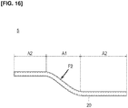
- the invention may be applied to an automobile panel 5 as a structure, such as that shown in Figure 16 .
- An automobile panel 5 is formed in the form of a panel with a reinforcing member 20 as the core member.
- the panel 5 is formed according to the RTM (Resin Transfer Molding) method.
- the irradiation intensity of the plasma P is adjusted by adjusting the plasma voltage, current, frequency, electrodes, and gas conditions.
- the irradiation intensity of the plasma P may be adjusted by providing a filter between the irradiation unit 120 and the reinforcing fibers 21. With this configuration, it is possible easily to adjust amount of the plasma P irradiated onto the reinforcing fibers 21 without manipulating the plasma voltage, current, frequency, electrode, and gas conditions.
- the liner 10 is cylindrical in shape, but it may have the form of a rectangular parallelepiped or the like.
Landscapes
- Engineering & Computer Science (AREA)
- Chemical & Material Sciences (AREA)
- Materials Engineering (AREA)
- Mechanical Engineering (AREA)
- Health & Medical Sciences (AREA)
- Medicinal Chemistry (AREA)
- Manufacturing & Machinery (AREA)
- Chemical Kinetics & Catalysis (AREA)
- General Engineering & Computer Science (AREA)
- Polymers & Plastics (AREA)
- Organic Chemistry (AREA)
- Textile Engineering (AREA)
- Physics & Mathematics (AREA)
- Plasma & Fusion (AREA)
- Toxicology (AREA)
- Filling Or Discharging Of Gas Storage Vessels (AREA)
- Chemical Or Physical Treatment Of Fibers (AREA)
Abstract
Description
- The present invention relates to a structure and a method for producing a structure.
- In recent years, reinforcing members, which are obtained by impregnating reinforcing fibers with resin, for use in automobile parts have attracted attention. More specifically, reinforcing members can be wound around the outer circumference of high-pressure gas storage containers in which hydrogen gas, etc., used as a fuel for automobiles, is stored. Reinforcing members are also used in automobile panels in order to reduce automobile weight.
- In general, since reinforcing fibers exhibit low adherence to resin, it is necessary to improve the adherence of the reinforcing fibers to resin.
- In relation to the foregoing, for example,
Patent Document 1 below discloses an adhesiveness improvement method for modifying the surface of an aromatic polyamide fiber and improving the adhesiveness by irradiating plasma on the aromatic polyamide fiber from a direction that is orthogonal to the arrangement surface of the fibers. - Patent Document 1: Japanese Laid-Open Patent Application No.
Sho 61-258065 - The stresses to which the above-described high-pressure gas storage containers and automobile panels are subjected differ and are location-dependent. However, product design is based on damage not occurring at locations that receive maximum stress, so that in terms of the overall product, there are locations at which the product thickness is excessive relative to the stress, which increases the weight of the product as a whole.
- In order to solve the problem described above, the object of the present invention is to provide a structure and a method for producing a structure that can achieve a reduction in weight for the product as a whole by reducing the wall thickness while maintaining suitable strength.
- A structure according to the present invention which realizes the above-described object comprises a reinforcing member made up of reinforcing fibers that have been impregnated with a resin. The reinforcing member includes a first region formed by irradiating the reinforcing fibers with a plasma, and a second region formed by irradiating the reinforcing fibers with a smaller amount of the plasma or formed without plasma irradiation. The structure is formed by providing with the structure with a reinforcing member such that the first region is positioned in a location that requires more strength than the second region.
- In addition, a method for producing the structure according to the present invention which realizes the above-described is a method for producing a structure comprising a reinforcing member made of reinforcing fibers impregnated with a resin. In the method for producing the structure, the reinforcing fibers are irradiated with a plasma and impregnated with the resin to form a first region in the reinforcing member. Then, the reinforcing fibers are irradiated with a smaller amount of the plasma than the first region, or plasma is not irradiated thereon, and impregnated with a resin to form a second region in the reinforcing member. Thereafter, the first region is positioned in a location that requires greater strength than the second region.
-
- [
Figure 1 ] is a view illustrating a high-pressure gas storage container according to the present embodiment. - [
Figure 2 ] is a view illustrating the state before a reinforcing member is wound around the outer perimeter surface of a liner. - [
Figure 3 ] is a view illustrating the state after a reinforcing member is wound around the outer perimeter surface of the liner. - [
Figure 4 ] is a cross-sectional view illustrating a portion of a reinforcing member made of reinforcing fibers impregnated with a resin. - [
Figure 5 ] is a graph illustrating the distribution of the plasma irradiation amount. - [
Figure 6 ] is a graph illustrating the relationship between the stress that is generated in a reinforcing layer and the material strength of the reinforcing layer. - [
Figure 7 ] is a view illustrating a device for producing the high-pressure gas storage container. - [
Figure 8 ] is a flowchart illustrating a method for producing a high-pressure gas storage container. - [
Figure 9 ] is a view illustrating a state in which a reinforcing member is wound around a liner. - [
Figure 10A ] is a view for explaining the effect on a high-pressure gas storage container. - [
Figure 10B ] is a view for explaining the effect on the high-pressure gas storage container. - [
Figure 10C ] is a view for explaining an effect on the high-pressure gas storage container. - [
Figure 11 ] is a graph illustrating the relationship between the applied pressure on the high-pressure gas storage container and strain. - [
Figure 12 ] is a view illustrating a state in which cracks are generated on the outer perimeter side of a high-pressure gas storage container. - [
Figure 13 ] is a graph illustrating the distribution of the plasma irradiation amount according to a first modified example. - [
Figure 14 ] is a graph illustrating the distribution of the plasma irradiation amount according to a second modified example. - [
Figure 15A ] is a view for explaining the effect on a high-pressure gas storage container according to a second modified example. - [
Figure 15B ] is a view for explaining an effect on the high-pressure gas storage container according to the second modified example. - [
Figure 15C ] is a view for explaining an effect on the high-pressure gas storage container according to the second modified example. - [
Figure 16 ] is a schematic view of an automobile panel. - Embodiments of the present invention will be explained below with reference to the appended drawings. In the explanations of the drawings, the same elements have been assigned the same reference symbols and redundant explanations have been omitted. Dimensional ratios of the drawings are exaggerated for the sake of convenience of explanation and may differ from actual ratios. In the present embodiment, a high-pressure
gas storage container 1 formed by winding reinforcingmembers 20 around theouter perimeter surface 10A of a liner 10 (corresponding to a core member) will be described as one example of a structure. -
Figure 1 is a view illustrating the high-pressuregas storage container 1 according to the present embodiment.Figure 2 is a view illustrating the state before the reinforcingmembers 20 are wound around theouter perimeter surface 10A of aliner 10.Figure 3 is a view illustrating the state after the reinforcingmembers 20 are wound around theouter perimeter surface 10A of theliner 10.Figure 4 is a cross-sectional view illustrating part of the reinforcingmember 20 made up of a plurality of reinforcingfibers 21 impregnated with aresin 22.Figure 5 is a graph illustrating the distribution of the irradiation amount of a plasma P.Figure 6 is a graph illustrating the relationship between the stress that is generated in a reinforcinglayer 30 and the material strength of thereinforcing layer 30. For ease of comprehension,Figure 1 shows a process in which the reinforcingmembers 20 are wound around theouter perimeter surface 10A of theliner 10. In addition, the irradiation of the plasma P and the state of impregnating with theresin 22 are omitted inFigure 2 . - In general, the high-pressure
gas storage container 1 according to the present embodiment comprises aliner 10 for holding a high-pressure gas, such as hydrogen gas, and a reinforcinglayer 30 that is formed by winding strip-shaped reinforcingmembers 20 around theouter perimeter surface 10A of theliner 10, as is illustrated inFigures 1-3 . - In addition, the high-pressure
gas storage container 1 is provided with the reinforcingmembers 20 that are made up of reinforcingfibers 21 that are impregnated withresin 22, as is illustrated inFigure 4 . The reinforcingmembers 20 include a first region A1 formed by irradiating the reinforcingfibers 21 with a plasma P and a second region A2 formed by irradiating the reinforcingfibers 21 with a smaller amount of the plasma P than the first region A1, as is illustrated inFigures 2 and5 . The first region A1 is positioned on the inner perimeter side of the reinforcinglayer 30, which requires greater strength than the second region A2. The configuration of the high-pressuregas storage container 1 according to the present embodiment will be described in detail below. - The
liner 10 is formed as a tank having the form of a cylinder. Theliner 10 has gas barrier properties and suppresses the permeation of high-pressure gas to the outside. Theliner 10 comprises a body portion 11 that is centered about the X axis direction, mirror-image portions 12 that are provided at each end of the body portion 11 in the X axis direction, and amouthpiece 13 that is provided in one of the mirror-image portions 12, as is illustrated inFigure 1 . - The body portion 11 is configured with a tubular shape, so as to extend in the X axis direction.
- The mirror-
image portions 12 are curved, so as to taper toward the outside in the X axis direction. - The
mouthpiece 13 is configured to project from the mirror-image portion 12 outwardly in the X axis direction. A pipe is connected, or a valve mechanism comprising an on-off valve or a pressure reducing valve is connected, to themouthpiece 13 in order to charge and discharge high-pressure gas into and from the high-pressuregas storage container 1. Themouthpiece 13 may be provided on the mirror-image portions 12 at each end. - A metal or synthetic resin material may be used to constitute the
liner 10. Examples of metals that can be used include iron, aluminum, and stainless steel. Examples of synthetic resins that can be used include polyethylene, polyamide, and polypropylene. - The reinforcing layers 30 are formed by winding a predetermined number of the reinforcing
members 20 around theouter perimeter surface 10A of theliner 10 from a windingstart end portion 20a to a windingtermination end portion 20b thereof, as is illustrated inFigures 2 and3 . In the present Specification, the windingstart end portion 20a means the end portion of a reinforcingmember 20 when winding around theouter perimeter surface 10A of theliner 10 is started, and a windingtermination end portion 20b means the end portion of the reinforcingmember 20 when winding around theouter perimeter surface 10A of theliner 10 is terminated. - The number of times the reinforcing
members 20 are wound, that is, the number of reinforcinglayers 30, is not particularly limited, but can be, for example, 20 to 30. By winding the reinforcingmembers 20 around theouter perimeter surface 10A of theliner 10, the reinforcinglayers 30 improve the pressure resistance strength of theliner 10. - The reinforcing
layer 30 includes ahoop layer 31 that is formed by winding the reinforcingmember 20 around the body portion 11 in the circumferential direction and ahelical layer 32 formed by winding the reinforcingmember 20 around the body portion 11 and the mirror-image portions 12 in a spiral shape, as is illustrated inFigure 1 . Thehoop layer 31 and thehelical layer 32 are stacked in alternating fashion. It is not necessary for thehoop layer 31 and thehelical layer 32 to be alternatingly stacked. That is, for example, the reinforcingmembers 20 can be wound to form twohoop layers 31 followed by twohelical layers 32. - Because the
hoop layer 31 is formed by winding the reinforcingmember 20 around the body portion 11, the hoop layer contributes to the tensile strength in the radial direction of the body portion 11. Because thehelical layer 32 is formed by winding the reinforcingmember 20 around the body portion 11 and the mirror-image portions 12, the strength in the X axis direction of the high-pressuregas storage container 1 is thereby ensured. - The reinforcing
members 20 that constitute the reinforcinglayer 30 are made up of reinforcingfibers 21 that are impregnated withresin 22, as is illustrated inFigure 4 . - The reinforcing
fibers 21 according to the present embodiment are formed by irradiating a plasma P thereon. In this manner, by irradiating the plasma P on the reinforcingfibers 21, it is possible to add an acidic functional group to the reinforcingfibers 21. As a result, the adhesiveness of theresin 22 to the reinforcingfibers 21 is improved, and the strength imparted by the reinforcingmembers 20 is improved. - In the reinforcing
fibers 21, a relatively large amount of plasma P is irradiated in a first region A1 on the inner perimeter side of the reinforcingmember 20 that constitutes the reinforcinglayer 30, and a relatively small amount of plasma P is irradiated in a second region A2 on the outer perimeter side of the reinforcingmember 20 that constitutes the reinforcingmember 30, as is illustrated inFigures 2 and5 . More specifically, the reinforcingfibers 21 are formed such that the irradiation amount of the plasma P is continuously gradually reduced from the windingstart end portion 20a to the windingtermination end portion 20b of the reinforcingmember 20, as is illustrated inFigure 5 . - In the reinforcing
member 20 made up of reinforcingfibers 21 onto which plasma P has been irradiated in this manner, the strength continuously gradually decreases from the windingstart end portion 20a to the windingtermination end portion 20b, in the same manner as the distribution of the irradiation amount of the plasma P. - Then, the reinforcing
member 20 is wound around theouter perimeter surface 10A of theliner 10 to create a reinforcinglayer 30. At this time, the strength distribution of the reinforcinglayer 30 in the radial direction r (refer toFigure 3 ) becomes such that the strength decreases from the inner perimeter side to the outer perimeter side in the radial direction r, as is indicated by the solid line inFigure 6 (refer to the arrow inFigure 6 ). - On the other hand, internal pressure acts on the high-pressure
gas storage container 1 from the high-pressure gas that is stored inside theliner 10, which causes stress σ to be generated in the reinforcinglayer 30. - The stress σ that is generated in the reinforcing
layer 30 is represented by the following formula (1) at a position R in the radial direction r, where the internal pressure of the high-pressure gas is P, the radius of the reinforcinglayer 30 at the outermost perimeter is r2, and the radius of the reinforcinglayer 30 at the innermost perimeter is r1, as is illustrated inFigure 3 . - [Formula 1]

- In this manner, the stress σ that is generated in the reinforcing
layer 30 continuously gradually decreases from the inner perimeter side to the outer perimeter side, as is indicated by the dotted line inFigure 6 . - In the present embodiment, the reinforcing
member 20 has a strength that can withstand the stress σ that is generated in the reinforcinglayer 30, as is illustrated inFigure 6 . - Examples of reinforcing
fibers 21 that can be used to constitute the reinforcingmember 20 include carbon fibers, glass fibers, and polyamide fibers. In the present embodiment, carbon fibers, which will be described as an example, have a low coefficient of thermal expansion, excellent dimensional stability, and little reduction in mechanical properties even at high temperatures. Reinforcingfibers 21 are formed in the state of a bundle of about 1,000 to 50,000 carbon fibers. - Examples of
resins 22 that can be used to constitute the reinforcingmember 20 include thermosetting resins and thermoplastic resins. Examples of thermosetting resins that can be used include epoxy resin, polyester resin, and phenol resin. Examples of thermoplastic resins that can be used include polyamide resin and polypropylene resin. - Next, a
manufacturing device 100 of the high-pressuregas storage container 1 according to the present embodiment will be described with reference toFigure 7. Figure 7 is a view illustrating amanufacturing device 100 of a high-pressuregas storage container 1. - The
manufacturing device 100 of the high-pressuregas storage container 1 comprises ahousing unit 110, anirradiation unit 120, animpregnation unit 130, atransport unit 140, adetection unit 150, and acontrol unit 160, as is illustrated inFigure 7 . - The
housing unit 110 houses bobbin-shaped reinforcingfibers 21. Thehousing portion 110 includes a settingpart 111 on which the bobbin-shaped reinforcingfibers 21 are set and four rollers 112-115 that maintain the tensile force on the reinforcingfibers 21. - The
irradiation unit 120 irradiates a plasma P onto the reinforcingfibers 21. As the present applicant has disclosed in Japanese Patent Application No.2014-181512 irradiation unit 120 preferably irradiates the plasma P from a direction that is tilted from thesurface 21A of the reinforcingfibers 21 in the Y axis direction (direction orthogonal to thesurface 21A). Theirradiation unit 120 preferably irradiates the plasma P onto thesurface 21A of the reinforcingfibers 21 from a direction that is tilted at least 30° with respect to the Y axis direction. By irradiating the plasma P from a direction that is tilted with respect to the Y axis direction in this manner, plasma gas is irradiated obliquely onto thesurface 21A of the reinforcingfibers 21, so that compression of the plasma gas is suppressed, and it is possible to carry out irradiation while allowing the high-temperature portion at the center to be released. Therefore, it is possible to efficiently irradiate plasma P onto the reinforcingfibers 21 and to add an acidic functional group to the reinforcingfibers 21 while reducing damage to the reinforcingfibers 21. - It is preferable to use an
AC power source 121 as the power source of theirradiation unit 120. TheAC power source 121 is grounded (grounded). - The irradiation intensity of the plasma P that is irradiated from the
irradiation unit 120 can be adjusted by adjusting the plasma voltage, current, frequency, electrodes, and gas conditions (composition of the gas). Hereinbelow, "adjusting the irradiation intensity of the plasma P" in the present Specification means adjusting the irradiation intensity of the plasma P by adjusting at least one of the above-described conditions of plasma voltage, current, frequency, electrodes, and gas. - One example of the irradiation condition of the plasma P will be described below.
- From the standpoint of facility in generating the plasma P, the plasma voltage is, for example, 200-400 V, and is preferably 260-280 V.
- From the standpoint of facility in generating the plasma P, the pulse repetition rate is, for example, 10-30 kHz, and is preferably 16-20 kHz.
- The plasma irradiation distance is, for example, 2-30 mm, and is preferably 10-15 mm. If the plasma irradiation distance is short, the reinforcing
fibers 21 may become damaged, and if the plasma irradiation distance is long, the surface modification effect is reduced. - The plasma irradiation time is, for example, 0.1-5.0 seconds, and is preferably 0.5-1.0 second. If the plasma irradiation time is short, the surface modification effect is reduced, and if the plasma irradiation time is long, the reinforcing
fibers 21 may become damaged. - An example of a plasma gas that can be used is a mixed gas containing 0.5% or more of oxygen, nitrogen, or helium.
- The
impregnation unit 130 impregnates the reinforcingfibers 21 that are irradiated with plasma P withresin 22. Theimpregnation unit 130 includes astorage unit 131 in which theresin 22 is stored and arotation unit 132 that rotates synchronously with the transport of the reinforcingfibers 21 while in contact with the reinforcingfibers 21, as is illustrated inFigure 7 . Theimpregnation unit 130 further includes anadjustment unit 133 that adjusts the amount ofresin 22 that adheres to therotation unit 132, and a pair ofrollers rotation unit 132 in the transport direction and that maintain the tensile force. In addition, theimpregnation unit 130 further includes aguide portion 136 that is provided on the downstream side of thedownstream side roller 135 and guides the reinforcingfibers 21 toward theliner 10. - The
storage unit 131 has a recessedportion 131A on the top, and theresin 22 is stored in the recessedportion 131A, as is illustrated inFigure 7 . - On the lower side, the
rotation unit 132 is in contact with theresin 22 that is stored in the recessedportion 131A, and, on the upper side, the rotation unit rotates while in contact with the reinforcingfibers 21 being transported. Therotation unit 132 rotates clockwise synchronously with the transport of the reinforcingfibers 21. With the clockwise rotation of therotation unit 132 in this manner, theresin 22 that adheres to the outer perimeter of therotation unit 132 is raised and adheres to the reinforcingfibers 21 on which the plasma P has been irradiated. It is thereby possible to impregnate the reinforcingfibers 21 with theresin 22 to form the reinforcingmembers 20. Therotation unit 132 maintains the tensile force on the reinforcingfibers 21 on which the plasma P has been irradiated together with therollers - The
adjustment unit 133 adjusts the amount of theresin 22 that adheres to the outer perimeter of therotation unit 132. Theadjustment unit 133 includes aremoval part 133A that removes only a predetermined amount of theresin 22 by coming in contact with theresin 22 that has adhered to the outer perimeter of therotation unit 132 and a movingpart 133B that moves theremoval part 133A so as to be able to move toward and away from therotation unit 132. - When the moving
part 133B moves theremoval part 133A to the right side inFigure 7 , a larger amount of theresin 22 that has adhered to the outer perimeter of therotation unit 132 is removed. On the other hand, when the movingpart 133B moves theremoval part 133A to the left side inFigure 7 , a smaller amount of theresin 22 that has adhered to the outer perimeter of therotation unit 132 is removed. - The
guide portion 136 guides the reinforcingfibers 21 that are impregnated with theresin 22 toward theliner 10. Theguide portion 136 is in the form of an L. - The configuration of the
impregnation unit 130 is not particularly limited as long as the configuration is capable of impregnating the reinforcingfibers 21 that are irradiated with plasma P withresin 22. - The
transport unit 140 winds the reinforcingmembers 20 that are formed by impregnating, with theresin 22, the reinforcingfibers 21 on thesurface 21A of which the plasma P has been irradiated, around theouter perimeter surface 10A of theliner 10, while transporting the reinforcingfibers 21 from the left side to the right side inFigure 7 . Thetransport unit 140 is a motor. - The
detection unit 150 detects the transport speed of the reinforcingfibers 21. A known speed sensor may be used as thedetection unit 150. The location where thedetection unit 150 is disposed is not particularly limited as long as the location is within a range in which the reinforcingfibers 21 are transported. - The
control unit 160 carries out operation control of theirradiation unit 120, thetransport unit 140, and the like. A control unit configured from a known microcomputer comprising a CPU, a RAM, a ROM, and the like can be used as thecontrol unit 160. - Next, a method for producing the high-pressure
gas storage container 1 according to the present embodiment will be described with reference to the flowchart ofFigure 8 . The method for producing the high-pressuregas storage container 1 according to the present embodiment is carried out according to the filament winding method. - First, the
transport unit 140 is operated in a state in which the bobbin-shaped reinforcingfibers 21 are set in the settingpart 111 and theliner 10 is set in the position shown inFigure 7 . Theliner 10 thereby rotates and the reinforcingfibers 21 are transported (S01). At this time, thedetection unit 150 detects the transport speed of the reinforcingfibers 21. - Next, the
irradiation unit 120 irradiates plasma P onto the reinforcingfibers 21 that are being transported (S02). - In the step for irradiating the plasma P, the plasma P is irradiated onto the reinforcing
fibers 21 that constitute the reinforcingmember 20 while the irradiation amount is continuously gradually reduced from the windingstart end portion 20a to the windingtermination end portion 20b of the reinforcing member 20 (refer toFigure 5 ). - The irradiation amount of plasma P is adjusted by adjusting the irradiation intensity of the
irradiation unit 120 and the transport speed of the reinforcingfibers 21. - That is, the irradiation amount of the plasma P onto the reinforcing
fibers 21 is continuously reduced by carrying out at least one of an adjustment operation to reduce the irradiation intensity of theirradiation unit 120 and an operation to increase the transport speed of the reinforcingfibers 21 from the front end to the rear end in the transport direction. - Next, the reinforcing
member 20 is formed by impregnating the reinforcingfibers 21 on which the plasma P has been irradiated (S03) with theresin 22. - The strength of the reinforcing
member 20 continuously gradually decreases from the windingstart end portion 20a to the windingtermination end portion 20b, in the same manner as the distribution of the irradiation amount of the plasma P. - Next, the reinforcing
member 20 is wound around theouter perimeter surface 10A of theliner 10 to create a reinforcing layer 30 (S04). - Because the strength of the reinforcing
member 20 continuously gradually decreases from the windingstart end portion 20a to the windingtermination end portion 20b, a reinforcinglayer 30 formed by the winding of the reinforcingmember 20 has the strength distribution in the radial direction r indicated by the solid line inFigure 6 . - In addition, if the
liner 10 is rotated at a constant angular velocity ω to wind the reinforcingmember 20 around theouter perimeter surface 10A of theliner 10, the transport speed of the reinforcingfibers 21 changes according to the radius at the time of winding, as is illustrated inFigure 9 . Specifically, when the reinforcingmember 20 is wound further on the outer perimeter side, the transport speed of the reinforcingfibers 21 is increased. Therefore, the transport speed of the reinforcingfibers 21 increases from the front end to the rear end in the transport direction. Accordingly, the irradiation amount of the plasma P onto the reinforcingfibers 21 is continuously gradually reduced from the windingstart end portion 20a to the windingtermination end portion 20b of the reinforcingmember 20. In the present embodiment, in addition to the foregoing, it is preferable to continuously gradually reduce the irradiation amount of the plasma P onto the reinforcingfibers 21 that constitute the reinforcingmember 20, from the windingstart end portion 20a to the windingtermination end portion 20b, by increasing the angular velocity ω, decreasing the irradiation intensity of theirradiation unit 120, and the like. - Next, the effects of the high-pressure
gas storage container 1 according to the present embodiment will be described with reference toFigures 10A-12 . -
Figure 10A is a graph illustrating the relationship between the stress that is generated in a reinforcing layer and the material strength of the reinforcing layer when plasma P is not irradiated. - Here, a strength design is implemented at the inner perimeter side of the reinforcing layer, where the greatest stress is generated. Therefore, an excessive strength design, corresponding to the area indicated by reference symbol S1 in
Figure 10A , is implemented, thereby increasing the weight of the high-pressure gas storage container. - In contrast, in the case of a reinforcing
layer 30 formed by winding the reinforcingmember 20 described above around theouter perimeter surface 10A of theliner 10, the strength of the reinforcinglayer 30 is enhanced so as to increase from the outer perimeter side toward the inner perimeter side, as is illustrated inFigure 10B (refer to the arrow inFigure 10B ). Then, as the strength of the reinforcinglayer 30 is enhanced, a margin of strength is accordingly generated on the inner perimeter side in addition to the outer perimeter side. - It is then possible to reduce the amount of the reinforcing
member 20 that is wound around theouter perimeter surface 10A of theliner 10 to an extent that does not exceed the strength distribution of the reinforcinglayer 30. As a result, although the stress that is generated in the reinforcinglayer 30 increases, as is illustrated inFigure 10C , the area indicated by reference symbol S2 inFigure 10C becomes smaller than the area indicated by the reference symbol S1 inFigure 10A . Thus, the design of excess strength will be relaxed. Therefore, it is possible to reduce the weight of the high-pressuregas storage container 1 by reducing the amount of the reinforcingmember 20 that is wound around theliner 10 to reduce the wall thickness of the reinforcinglayer 30 while maintaining suitable strength. - In addition,
Figure 11 is a graph illustrating the relationship between pressure that acts on the high-pressure gas storage container and strain. InFigure 11 , the horizontal axis represents pressure and the vertical axis represents strain. Additionally, the straight line that includes the rhomboidal plot points inFigure 11 illustrates the relationship between the pressure of the high-pressure gas storage container containing reinforcing fibers onto which plasma has not been irradiated and strain. In addition, the straight line that includes the rectangular plot points illustrates the relationship between the pressure of the high-pressuregas storage container 1 according to the present embodiment and strain.Figure 11 also shows empirical values for the strain, which were measured with a strain gauge affixed to the outer perimeter side of the reinforcing layer. - As is illustrated in
Figure 11 , it can be seen that the numerical value of the strain is reduced by irradiating plasma P onto the reinforcingfibers 21. That is, it can be seen that the strength of the reinforcingmembers 20 is improved by irradiation of the plasma P. - In addition, according to the high-pressure
gas storage container 1 of the present embodiment, the reinforcingfibers 21 that constitute the reinforcingmember 20 are formed such that the irradiation amount of the plasma P is continuously gradually reduced from the windingstart end portion 20a to the windingtermination end portion 20b of the reinforcingmember 20 with respect to theliner 10. Thus, it is possible to increase the strength of the inner perimeter side more than the outer perimeter side of the reinforcinglayer 30. Therefore, when an unexpected external force F1 acts on the high-pressuregas storage container 1 on the outer perimeter side, it is possible to preferentially generate cracks C on the outer perimeter side, as is illustrated inFigure 12 . Therefore, it is possible to detect those portions in which cracks have occurred by visual inspection, and thus to improve detectability. - In addition, according to the high-pressure
gas storage container 1 of the present embodiment, the reinforcingfibers 21 that constitute the reinforcingmember 20 are formed such that the irradiation amount of the plasma P is continuously gradually reduced from the windingstart end portion 20a to the windingtermination end portion 20b of the reinforcingmember 20 with respect to theliner 10. Therefore, because the strength distribution of the reinforcingmember 20 continuously gradually decreases from the windingstart end portion 20a to the windingtermination end portion 20b, it is possible to suitably suppress the occurrence of shear fractures between thelayers - As described above, the high-pressure
gas storage container 1 according to the present embodiment is a structure comprising a reinforcingmember 20 made of reinforcingfibers 21 impregnated with aresin 22. The reinforcingmember 20 includes a first region A1 formed by irradiating the reinforcingfibers 21 with plasma P, and a second region A2 formed by irradiating the reinforcingfibers 21 with a smaller amount of the plasma P than the first region A1. In addition, the high-pressuregas storage container 1 is formed by providing the container with the reinforcingmember 20 such that the first region A1 is positioned in a location that requires greater strength than the second region A2. According to a high-pressuregas storage container 1 configured in this manner, it is possible to add an acidic functional group to the reinforcingfibers 21 by irradiating plasma P on the reinforcingfibers 21. As a result, the adhesiveness of theresin 22 to the reinforcingfibers 21 is improved, as is the strength of the reinforcingmember 20. Then, the first region A1 where the strength has been relatively enhanced by irradiating relatively more plasma P is positioned on the inner perimeter side of the reinforcinglayer 30, where strength is required. Therefore, even if the wall thickness is reduced, because the strength has been enhanced by irradiating the plasma P, it is possible to maintain suitable strength. Thus, it is possible achieve a reduction in overall weight by reducing the wall thickness while maintaining suitable strength. - In addition, the high-pressure
gas storage container 1 further comprises a core member, which is theliner 10, and the reinforcingmember 20 has a strip shape. The strip-shaped reinforcingmember 20 is wound around theouter perimeter surface 10A of theliner 10 to constitute a reinforcinglayer 30 made up of a plurality of layers. In the reinforcinglayer 30, the inner perimeter side of the reinforcinglayer 30 is constituted by the first region A1 and the outer perimeter side of the reinforcinglayer 30 is constituted from the second region A2. According to a structure configured in this manner, it is possible to increase the strength of the inner perimeter side of the reinforcinglayer 30. Therefore, it is possible to reduce the amount of the reinforcingmember 20 that is wound, even around a structure onto which high pressure acts on the inner perimeter side of the reinforcinglayer 30, while maintaining suitable strength. Therefore, it is possible achieve a reduction in the overall weight of the product by reducing the wall thickness of the reinforcinglayer 30. - Additionally, the core member is a
liner 10 that houses high-pressure gas. It is thus possible to reduce the amount of the reinforcingmember 20 that is wound around the high-pressuregas storage container 1, while maintaining suitable strength. Therefore, it is possible achieve a reduction in the overall weight of the product by reducing the wall thickness of the reinforcinglayer 30. - In addition, the reinforcing
member 20 is formed such that the irradiation amount of the plasma P onto the reinforcingfibers 21 is continuously gradually reduced from the windingstart end portion 20a to the windingtermination end portion 20b with respect to theliner 10. According to this configuration, because the strength of the reinforcingmember 20 continuously gradually decreases from the windingstart end portion 20a to the windingtermination end portion 20b, it is possible to suitably suppress the occurrence of shear fractures between thelayers - Additionally, as described above, the method for producing a high-pressure
gas storage container 1 according to the present embodiment is a method for producing a high-pressuregas storage container 1 comprising a reinforcingmember 20 made of reinforcingfibers 21 impregnated with aresin 22. In the method for producing the high-pressuregas storage container 1, reinforcingfibers 21 are irradiated with a plasma P and impregnated with aresin 22 to form a first region A1 in the reinforcingmember 20. The reinforcingfibers 21 are then irradiated with a smaller amount of the plasma P than the first region A1 and impregnated with aresin 22 to form a second region A2 of the reinforcingmember 20. The first region A1 is then positioned in a location that requires greater strength than the second region A2. According to this production method, it is possible to add an acidic functional group to the reinforcingfibers 21 by irradiating plasma P onto the reinforcingfibers 21. As a result, the adhesiveness of theresin 22 to the reinforcingfibers 21 is improved, as is the strength of the reinforcingmember 20. Then, the first region A1 where the strength has been relatively enhanced by irradiating relatively more plasma P is positioned on the inner perimeter side of the reinforcinglayer 30, where strength is required. Therefore, even if the wall thickness is reduced, because the strength has been enhanced by irradiation of the plasma P, it is possible to maintain suitable strength. Thus, it is possible to provide a high-pressuregas storage container 1 that can realize a reduction in overall weight by reducing the wall thickness while maintaining a suitable strength. - Additionally, that reinforcing
fibers 21 that are formed in a strip shape are transported and the reinforcingfibers 21 are irradiated with plasma P on the front end in the transport direction and impregnated with aresin 22 to form a first region A1 in the reinforcingmember 20. In addition, the reinforcingfibers 21 are irradiated with a smaller amount of the plasma P than the first region A1 on the rear end in the transport direction and impregnated with aresin 22 to form a second region A2 in the reinforcingmember 20. The reinforcingmember 20 in which the first region A1 and the second region A2 have been formed is then wound around the core member, which is theliner 10. According to this production method, it is possible to increase the strength of the inner perimeter side of the reinforcinglayer 30. Therefore, it is possible to reduce the amount of the reinforcingmember 20 that is wound, even around a structure onto which high pressure acts on the inner perimeter side of the reinforcinglayer 30, while maintaining a suitable strength. Therefore, it is possible achieve a reduction in the overall weight of the product by reducing the wall thickness of the reinforcinglayer 30. - In addition, the core member is a
liner 10 that houses high-pressure gas. Accordingly, it is possible to reduce the amount of the reinforcingmember 20 that is wound around the high-pressuregas storage container 1 while maintaining a suitable strength. Therefore, it is possible achieve an overall reduction in weight of the product by reducing the wall thickness of the reinforcinglayer 30. - In addition, the plasma P is irradiated, as the irradiated amount is continuously gradually reduced, onto the reinforcing
fibers 21, from the windingstart end portion 20a to the windingtermination end portion 20b of the reinforcingmember 20 with respect to theliner 10. According to this production method, it is possible to produce a high-pressure gas storage container in which the strength of the reinforcingmember 20 continuously gradually decreases from the windingstart end portion 20a to the windingtermination end portion 20b. Accordingly, it is possible to suitably suppress the occurrence of shear fractures between thelayers - In addition, the irradiation amount of the plasma P is adjusted by adjusting at least one of the plasma voltage, current, frequency, electrodes, and gas conditions to adjust the irradiation intensity of the plasma P. According to this production method, it is possible to easily adjust the irradiation amount of the plasma P with respect to the reinforcing
fibers 21. Therefore, it is possible to adjust the strength of the reinforcingmember 20 such that the area indicated by the reference symbol S2 inFigure 10C is reduced. In this manner, the design of excess strength can be further relaxed by reduction of the area indicated by the reference symbol S2. - Additionally, the irradiation amount of the plasma P can be adjusted by changing the transport speed of the reinforcing
fibers 21 during irradiation of plasma P onto the reinforcingfibers 21. According to this production method, it is possible to increase the transport speed of the reinforcingfibers 21 during irradiation of plasma P onto the reinforcingfibers 21 on the outer perimeter side of the reinforcinglayer 30, where the irradiation amount of the plasma P onto the reinforcingfibers 21 is low. Therefore, it is possible to reduce the manufacturing time and to enhance productivity. - Additionally, the plasma P is irradiated onto the
surface 21A of the reinforcingfibers 21 from a direction that is tilted from the Y axis direction that is orthogonal to thesurface 21A. According to this production method, because the plasma gas is irradiated from a direction that is tilted from thesurface 21A of the reinforcingfibers 21, compression of the plasma gas is suppressed, and it is possible to carry out irradiation while allowing the high-temperature portion at the center to be released. Therefore, it is possible to efficiently irradiate plasma P onto the reinforcingfibers 21 and to add an acidic functional group to the reinforcingfibers 21 while reducing damage to the reinforcingfibers 21. - A first modified example of the above-described embodiment will be described below.
- A high-pressure gas storage container according to the first modified example is different from the high-pressure
gas storage container 1 according to the embodiment described above in the distribution of the irradiation amount of the plasma P onto the reinforcingfibers 21. -
Figure 13 is a graph illustrating a distribution of the irradiation amount of the plasma P according to the first modified example. - The reinforcing
fibers 21 of the high-pressure gas storage container according to the first modified example are formed such that the irradiation amount of the plasma P is gradually reduced in stepwise fashion from the windingstart end portion 20a to the windingtermination end portion 20b of the reinforcingmember 20 with respect to theliner 10, as is illustrated inFigure 13 . - More specifically, a set amount of plasma P is irradiated onto a
hoop layer 31a, as is illustrated inFigure 13 . Additionally, plasma P in a smaller amount than in thehoop layer 31a is irradiated onto an adjacenthelical layer 32 on the outer perimeter side of thehoop layer 31a. Furthermore, plasma P in a smaller amount than in thehelical layer 32 is irradiated onto anadjacent hoop layer 31b on the outer perimeter side of thehelical layer 32. Thereafter, the irradiation amount of the plasma P is gradually reduced in stepwise fashion toward the outer perimeter side, in the order ofhelical layer 32 andhoop layer 31. - In a reinforcing
member 20 made up of reinforcingfibers 21 onto which plasma P has been irradiated in this manner, the strength continuously gradually decreases from the windingstart end portion 20a to the windingtermination end portion 20b, in the same manner as the distribution of the irradiation amount of the plasma P. - Then, if such a reinforcing
member 20 is wound around theouter perimeter surface 10A of theliner 10 to form a reinforcinglayer 30, the strength distribution along the radial direction r of the reinforcinglayer 30 decreases from the inner perimeter side to the outer perimeter side in the radial direction r, in the same manner as the strength distribution of the reinforcinglayer 30 according to the embodiment described above. - Next, a method for producing the high-pressure gas storage container according to the first modified example will be described.
- Here, only the step for irradiating plasma P will be described.
- In the step for irradiating the plasma P, the plasma P is irradiated, while the irradiated amount is gradually reduced in stepwise fashion, onto the reinforcing
fibers 21 that constitute the reinforcingmember 20, from the windingstart end portion 20a to the windingtermination end portion 20b of the reinforcingmember 20 with respect to theliner 10. The step for irradiating the plasma P will be described in detail below. - The step for irradiating plasma P includes a first irradiation step for irradiating a set amount of the plasma P onto the reinforcing
fibers 21 that constitute the reinforcingmember 20 that is wound in/ thehoop layer 31. Additionally, the step for irradiating plasma P includes a second irradiation step for irradiating a set amount of the plasma P onto the reinforcingfibers 21 that constitute the reinforcingmember 20 that is wound in thehelical layer 32. - The first irradiation step and the second irradiation step are carried out in alternating fashion, and the irradiation amount of the plasma P is reduced when switching from the first irradiation step to the second irradiation step, and when switching from the second irradiation step to the first irradiation step.
- As described above, in the high-pressure gas storage container according to the first modified example, the reinforcing
member 20 is formed such that the irradiation amount of the plasma P onto the reinforcingfibers 21 is gradually reduced in stepwise fashion from the windingstart end portion 20a to the windingtermination end portion 20b with respect to theliner 10. According to a high-pressure gas storage container configured in this manner, it is possible to increase the strength of the inner perimeter side of the reinforcinglayer 30. Therefore, it is possible to reduce the amount of the reinforcingmember 20 that is wound, even around a high-pressure gas storage container on which high pressure acts on the inner perimeter side of the reinforcinglayer 30, while maintaining a suitable strength. Therefore, it is possible achieve an overall reduction in weight of the product by reducing the wall thickness of the reinforcinglayer 30. - Additionally, the reinforcing
layer 30 is formed such that the irradiation amount of the plasma P onto the reinforcingfibers 21 is gradually reduced in stepwise fashion for eachlayer layer layer 30 in onelayer - Additionally, in the method for producing a high-pressure gas storage container according to the first modified example, the plasma P is irradiated, while the irradiated amount is gradually reduced in stepwise fashion, onto the reinforcing
fibers 21 from the windingstart end portion 20a to the windingtermination end portion 20b of the reinforcingmember 20 with respect to theliner 10. According to this production method, it is possible to produce a high-pressure gas storage container in which the strength of the inner perimeter side of the reinforcinglayer 30 is high. Therefore, it is possible to reduce the amount of the reinforcingmember 20 that is wound, even around a high-pressure gas storage container on which high pressure acts at the inner perimeter side, while maintaining a suitable strength. Therefore, it is possible achieve an overall reduction in weight of the product by reducing the wall thickness of the reinforcinglayer 30. - In addition, when plasma P is irradiated onto the reinforcing
fibers 21, the irradiation amount of the plasma P is reduced when the irradiation target of the plasma P switches from the reinforcingfibers 21 in one layer to the reinforcingfibers 21 in another adjacent layer on the outer perimeter side. According to this production method, the irradiation amount of the plasma P in onelayer layer 30 in onelayer - A second modified example of the above-described embodiment will be described below.
- A high-pressure gas storage container according to the second modified example is different from the high-pressure
gas storage container 1 according to the embodiment described above in the distribution of the irradiation amount of the plasma P onto the reinforcingfibers 21. -
Figure 14 is a graph illustrating the distribution of the irradiation amount of the plasma P according to a second modified example. - In the second modified example, a set amount of the plasma P is irradiated onto the reinforcing
fibers 21 that constitute the reinforcingmember 20 from the windingstart end portion 20a to anintermediate portion 20c (refer toFigure 2 ) positioned between the windingstart end portion 20a and the windingtermination end portion 20b, as is illustrated inFigure 14 . In addition, plasma P is not irradiated onto the reinforcingfibers 21 that constitute the reinforcingmember 20 from theintermediate portion 20c to the windingtermination end portion 20b. - A reinforcing member made up of reinforcing
fibers 21 onto which plasma P has been irradiated in this manner has a strength distribution in which the strength increases only from the windingstart end portion 20a to theintermediate portion 20c, in the same manner as the distribution of the irradiation amount of the plasma P. - Next, a method for producing the high-pressure gas storage container according to the second modified example will be described.
- Here, only the step for irradiating the plasma P will be described.
- In the step for irradiating the plasma P, a set amount of the plasma P is irradiated onto the reinforcing
fibers 21 that constitute the reinforcingmember 20 from the windingstart end portion 20a to theintermediate portion 20c. Thereafter, irradiation of the plasma P is stopped. That is, plasma P is not irradiated onto the reinforcingfibers 21 that constitute the reinforcingmember 20 from theintermediate portion 20c to the windingtermination end portion 20b. - Next, the effects of the high-pressure gas storage container according to the second modified example will be described with reference to
Figures 15A-15C . -
Figure 15A is a graph illustrating the relationship between the stress that is generated in a reinforcing layer and the material strength of the reinforcing layer when plasma P is not irradiated. - Here, as was described above, strength design is implemented at the inner perimeter side of the reinforcing layer, where the greatest stress is generated. Therefore, an excessive strength design, corresponding to the area indicated by reference symbol S1 in
Figure 15A , is implemented, thereby increasing the weight of the high-pressure gas storage container. - In contrast, in the case of a reinforcing
layer 30 formed by winding the reinforcingmember 20 according to the second modified example around theouter perimeter surface 10A of theliner 10, the strength of the inner perimeter side of the reinforcinglayer 30 is enhanced, as is illustrated inFigure 15B (refer to the arrow inFigure 15B ). Then, as the strength of the inner perimeter side of the reinforcinglayer 30 is enhanced, a margin of strength is accordingly generated on the inner perimeter side in addition to the outer perimeter side. - It is then possible to reduce the amount of the reinforcing
member 20 that is wound around theouter perimeter surface 10A of theliner 10 to an extent that does not exceed the strength distribution of the reinforcinglayer 30. As a result, although the stress that is generated in the reinforcinglayer 30 increases, as is illustrated inFigure 15C , the area indicated by reference symbol S3 inFigure 15C becomes smaller than the area indicated by the reference symbol S1 inFigure 15A . Accordingly, the design of excess strength can be relaxed. Therefore, it is possible to reduce the weight of the high-pressure gas storage container by reducing the amount of the reinforcingmember 20 that is wound around theliner 10 to reduce the wall thickness of the reinforcinglayer 30 while maintaining a suitable strength. - As described above, in the high-pressure gas storage container according to the second modified example, the reinforcing
member 20 from the windingstart end portion 20a to theintermediate portion 20c is formed such that a set amount of the plasma P is irradiated onto the reinforcingfibers 21. Also, in the reinforcingmember 20 from theintermediate portion 20c to the windingtermination end portion 20b, plasma P is not irradiated onto the reinforcingfibers 21. When such a reinforcingmember 20 is produced, the irradiation of the plasma P may be stopped at theintermediate portion 20c. Therefore, it is possible to easily produce the high-pressure gas storage container. - In addition, as described above, in the method for producing a high-pressure gas storage container according to the second modified example, a set amount of plasma P is irradiated onto the reinforcing
fibers 21 that constitute the reinforcingmember 20 from the windingstart end portion 20a to theintermediate portion 20c. Also, plasma P is not irradiated onto the reinforcingfibers 21 that constitute the reinforcingmember 20 from theintermediate portion 20c to the windingtermination end portion 20b. According to this production method, because it suffices to stop the irradiation of the plasma P at theintermediate portion 20c, it is possible to easily produce a high-pressure gas storage container. - The present invention is not limited to the embodiment and modified example described above, and various modifications are possible within the scope of the claims.
- In the above-described embodiment, the first modified example, and the second modified example, a high-pressure gas storage container formed by winding a reinforcing
member 20 around theouter perimeter surface 10A of aliner 10 was described as an example of a structure. However, the invention may be applied to anautomobile panel 5 as a structure, such as that shown inFigure 16 . Anautomobile panel 5 is formed in the form of a panel with a reinforcingmember 20 as the core member. Thepanel 5 is formed according to the RTM (Resin Transfer Molding) method. For example, in the case that an external force F2 shown inFigure 16 acts on thepanel 5, a first region A1 where the strength has been relatively enhanced by irradiating relatively more plasma P is positioned at the periphery of the portion on which the external force F2 acts. As a result, even if the wall thickness is reduced, because the strength has been enhanced by irradiating the plasma P, it is possible to maintain a suitable strength. Accordingly, it is possible to provide apanel 5 for which an overall reduction in weight can be achieved by reducing the wall thickness while maintaining suitable strength. - Additionally, in the embodiment described above, the irradiation intensity of the plasma P is adjusted by adjusting the plasma voltage, current, frequency, electrodes, and gas conditions. However, the irradiation intensity of the plasma P may be adjusted by providing a filter between the
irradiation unit 120 and the reinforcingfibers 21. With this configuration, it is possible easily to adjust amount of the plasma P irradiated onto the reinforcingfibers 21 without manipulating the plasma voltage, current, frequency, electrode, and gas conditions. - In addition, in the above-described embodiment, the
liner 10 is cylindrical in shape, but it may have the form of a rectangular parallelepiped or the like. - Furthermore, the present application is based on Japanese Patent Application No.
2016-042733 filed on March 4, 2016 -
- 1
- High-pressure gas storage container (structure),
- 5
- Automobile panel (structure),
- 10
- Liner,
- 10A
- Outer perimeter surface of liner,
- 11
- Body portion,
- 12
- Mirror-image portion,
- 20
- Reinforcing member
- 21
- Reinforcing fiber,
- 22
- Resin,
- 30
- Reinforcing layer,
- 31
- Hoop layer,
- 32
- Helical layer,
- A1
- First region,
- A2
- Second region,
- P
- Plasma.
Claims (20)
- A structure comprising: a reinforcing member made up of reinforcing fibers impregnated with a resin, wherein
the reinforcing member includes a first region formed by irradiating the reinforcing fibers with a plasma, and a second region formed by irradiating the reinforcing fibers with a smaller amount of the plasma than the first region or without plasma irradiation, and
the reinforcing member being provided such that the first region is positioned in a location that requires greater strength than the second region. - The structure according to claim 1, further comprising
a core member, wherein
the reinforcing member is strip-shaped,
the strip-shaped reinforcing member is wound around an outer perimeter surface of the core member to constitute a reinforcing layer made up of a plurality of layers, and
in the reinforcing layer, an inner perimeter side of the reinforcing layer is constituted by the first region and an outer perimeter side of the reinforcing layer is constituted from the second region. - The structure according to claim 2, wherein the core member is a liner that houses high-pressure gas.
- The structure according to claim 2 or 3, wherein the reinforcing member is formed such that the amount of the plasma irradiated onto the reinforcing fibers is continuously gradually reduced from a winding start end portion to a winding termination end portion with respect to the core member.
- The structure according to claim 2 or 3, wherein the reinforcing member is formed such that the amount of the plasma irradiated onto the reinforcing fibers is gradually reduced in stepwise fashion from a winding start end portion to a winding termination end portion with respect to the core member.
- The structure according to claim 5, wherein the reinforcing layer is formed such that the amount of the plasma irradiated onto the reinforcing fibers is gradually reduced in stepwise fashion for each of the layers.
- The structure according to claim 2 or 3, wherein
the reinforcing member from a winding start end portion with respect to the core member to an intermediate portion that is positioned between the winding start end portion and a winding termination end portion is formed such that a set amount of the plasma is irradiated onto the reinforcing fibers, and
in the reinforcing member from the intermediate portion to the winding termination end portion, the plasma is not irradiated onto the reinforcing fibers. - The structure according to claim 1, wherein the structure is formed in the form of a panel with the reinforcing member as a core member.
- A method for producing a structure comprising a reinforcing member made up of reinforcing fibers impregnated with a resin, comprising:forming a first region in the reinforcing member by irradiating the reinforcing fibers with plasma and impregnating with the resin;forming a second region in the reinforcing member by irradiating the reinforcing fibers with a smaller amount of plasma than the first region, or without plasma irradiation, and impregnating with the resin; andpositioning the first region in a location that requires greater strength than the second region.
- The method for producing a structure according to claim 9, wherein
the reinforcing fibers are transported in a strip shape form,
the irradiating of the reinforcing fibers with the plasma and the impregnating with the resin on a front end in a transport direction to form the first region in the reinforcing member,
the irradiating of the reinforcing fibers with the smaller amount of the plasma than the first region and the impregnating with the resin on a rear end in the transport direction to form the second region in the reinforcing member, and
winding the first region and the second region of the reinforcing member around a core member. - The method for producing a structure according to claim 10, wherein the core member of the structure is a liner in which a high-pressure gas is stored.
- The method for producing a structure according to claim 10 or 11, wherein the reinforcing member is formed such that the plasma is irradiated onto the reinforcing fibers while the irradiated amount is continuously reduced from a winding start end portion to a winding termination end portion with respect to the core member.
- The method for producing a structure according to claim 10 or 11, wherein the reinforcing member is formed such that the plasma is irradiated onto the reinforcing fibers while the irradiated amount is reduced in stepwise fashion from a winding start end portion to a winding termination end portion with respect to the core member.
- The method for producing a structure according to claim 13, wherein
when the reinforcing fibers are irradiated with the plasma,
the plasma irradiation amount is reduced when an irradiation target of the plasma switches from the reinforcing fibers that constitute the reinforcing member that is wound in one layer to the reinforcing fibers that constitute the reinforcing member that is wound in another adjacent layer on an outer perimeter side. - The method for producing a structure according to claim 10 or 11, wherein a set amount of plasma is irradiated onto the reinforcing fibers that constitute the reinforcing member from a winding start end portion of the reinforcing member with respect to the core member to an intermediate portion that is positioned between the winding start end portion and a winding termination end portion, and the plasma is not irradiated onto the reinforcing fibers that constitute the reinforcing member from the intermediate portion of the reinforcing member to the winding termination end portion.
- The method for producing a structure according to claim 9, wherein the structure has the form of a panel with the reinforcing member as a core member.
- The method for producing a structure according to any one of claims 9 to 16, wherein the plasma irradiation amount is adjusted by adjusting at least one of the plasma voltage, current, frequency, electrodes, and gas conditions to adjust an irradiation intensity of the plasma.
- The method for producing a structure according to any one of claims 9 to 17, wherein the plasma irradiation amount is adjusted by providing a filter between an irradiation unit for the plasma and the reinforcing fibers to adjust the irradiation intensity of the plasma.
- The method for producing a structure according to any one of claims 9 to 18, wherein the plasma irradiation amount is adjusted by changing a transport speed of the reinforcing fibers during irradiation of the reinforcing fibers with the plasma.
- The method for producing a structure according to any one of claims 9 to 19, wherein the plasma is irradiated onto a surface of the reinforcing fibers from a direction that is tilted with respect to a direction that is orthogonal to the surface.
Applications Claiming Priority (2)
| Application Number | Priority Date | Filing Date | Title |
|---|---|---|---|
| JP2016042733 | 2016-03-04 | ||
| PCT/JP2016/078931 WO2017149818A1 (en) | 2016-03-04 | 2016-09-29 | Structure body, and method for manufacturing structure body |
Publications (3)
| Publication Number | Publication Date |
|---|---|
| EP3425258A1 true EP3425258A1 (en) | 2019-01-09 |
| EP3425258A4 EP3425258A4 (en) | 2019-03-06 |
| EP3425258B1 EP3425258B1 (en) | 2020-05-27 |
Family
ID=59743708
Family Applications (1)
| Application Number | Title | Priority Date | Filing Date |
|---|---|---|---|
| EP16892655.8A Active EP3425258B1 (en) | 2016-03-04 | 2016-09-29 | Structure body, and method for manufacturing structure body |
Country Status (7)
| Country | Link |
|---|---|
| US (1) | US11040479B2 (en) |
| EP (1) | EP3425258B1 (en) |
| JP (1) | JP6583530B2 (en) |
| KR (2) | KR101998540B1 (en) |
| CN (1) | CN108779893B (en) |
| CA (1) | CA3016388C (en) |
| WO (1) | WO2017149818A1 (en) |
Families Citing this family (5)
| Publication number | Priority date | Publication date | Assignee | Title |
|---|---|---|---|---|
| JP6927139B2 (en) * | 2018-05-10 | 2021-08-25 | トヨタ自動車株式会社 | Filament winding equipment, filament winding design method and tank manufacturing method |
| JP7207103B2 (en) * | 2019-04-01 | 2023-01-18 | トヨタ自動車株式会社 | High pressure tank and its manufacturing method |
| US12358365B1 (en) * | 2021-05-07 | 2025-07-15 | Agility Fuel Systems Llc | Vehicles having composite interwoven gas containment assemblies |
| DE102021123510A1 (en) * | 2021-09-10 | 2023-03-16 | Schmidt & Heinzmann Gmbh & Co Kg | Production device, in particular SMC production device, for the production of duroplastic semi-finished products |
| CN115307052B (en) * | 2022-08-15 | 2024-05-28 | 佛山仙湖实验室 | An optimization design method for the winding reinforcement layer of a composite gas cylinder and its application |
Family Cites Families (12)
| Publication number | Priority date | Publication date | Assignee | Title |
|---|---|---|---|---|
| JPS61258065A (en) | 1985-05-10 | 1986-11-15 | アイシ−エス株式会社 | Method and apparatus fur improving adhesiveness of aromatic polyamide fiber |
| JPS63144153A (en) | 1986-12-05 | 1988-06-16 | 群馬工業高等専門学校長 | Carbon fiber reinforced cement composite material and manufacture |
| US5053246A (en) | 1990-03-30 | 1991-10-01 | The Goodyear Tire & Rubber Company | Process for the surface treatment of polymers for reinforcement-to-rubber adhesion |
| JPH09280496A (en) | 1996-04-18 | 1997-10-31 | Toray Ind Inc | Pressure vessel and method of manufacturing the same |
| US6514449B1 (en) * | 2000-09-22 | 2003-02-04 | Ut-Battelle, Llc | Microwave and plasma-assisted modification of composite fiber surface topography |
| JP2005337394A (en) | 2004-05-27 | 2005-12-08 | Nippon Oil Corp | Fiber reinforced pressure vessel and method for manufacturing the same |
| US8227051B1 (en) * | 2004-06-24 | 2012-07-24 | UT-Battle, LLC | Apparatus and method for carbon fiber surface treatment |
| JP2006233354A (en) | 2005-02-24 | 2006-09-07 | Teijin Techno Products Ltd | Method for producing rubber reinforcing fiber |
| CN102388256B (en) * | 2009-04-10 | 2015-03-18 | 丰田自动车株式会社 | Tank and fabrication method thereof |
| BRPI1014711A2 (en) | 2009-04-27 | 2016-04-12 | Applied Nanostrctured Solutions Llc | cnt-based resistance heating to defrost composite structures |
| CN103206612B (en) | 2013-03-06 | 2015-07-01 | 清华大学深圳研究生院 | Light-metal-lined composite cylinder fully-wrapped with basalt fiber, and production process thereof |
| JP6319000B2 (en) | 2014-09-05 | 2018-05-09 | 日産自動車株式会社 | Method and apparatus for surface modification of reinforced substrate |
-
2016
- 2016-09-29 KR KR1020187027151A patent/KR101998540B1/en not_active Expired - Fee Related
- 2016-09-29 WO PCT/JP2016/078931 patent/WO2017149818A1/en not_active Ceased
- 2016-09-29 EP EP16892655.8A patent/EP3425258B1/en active Active
- 2016-09-29 JP JP2018502512A patent/JP6583530B2/en not_active Expired - Fee Related
- 2016-09-29 KR KR1020197015080A patent/KR102164167B1/en not_active Expired - Fee Related
- 2016-09-29 CN CN201680083175.0A patent/CN108779893B/en not_active Expired - Fee Related
- 2016-09-29 CA CA3016388A patent/CA3016388C/en active Active
- 2016-09-29 US US16/081,452 patent/US11040479B2/en not_active Expired - Fee Related
Also Published As
| Publication number | Publication date |
|---|---|
| JPWO2017149818A1 (en) | 2019-01-31 |
| KR20180108859A (en) | 2018-10-04 |
| JP6583530B2 (en) | 2019-10-02 |
| KR101998540B1 (en) | 2019-07-09 |
| CA3016388C (en) | 2020-01-28 |
| KR20190060017A (en) | 2019-05-31 |
| KR102164167B1 (en) | 2020-10-12 |
| US11040479B2 (en) | 2021-06-22 |
| CN108779893A (en) | 2018-11-09 |
| WO2017149818A1 (en) | 2017-09-08 |
| CA3016388A1 (en) | 2017-09-08 |
| EP3425258A4 (en) | 2019-03-06 |
| US20190099937A1 (en) | 2019-04-04 |
| EP3425258B1 (en) | 2020-05-27 |
| CN108779893B (en) | 2019-07-23 |
Similar Documents
| Publication | Publication Date | Title |
|---|---|---|
| US11590725B2 (en) | Method for producing high-pressure gas storage container | |
| EP3425258B1 (en) | Structure body, and method for manufacturing structure body | |
| EP2433045B1 (en) | High pressure storage device and method | |
| JP5531040B2 (en) | Manufacturing method of high-pressure gas tank | |
| EP0130641A2 (en) | Method of manufacturing tanks, containers, pipes, etc. | |
| KR20160142234A (en) | Manufacturing method of tank | |
| CN105333302B (en) | A kind of preparation method of Large Copacity high-pressure hydrogen storage winding composite shell | |
| US20190120429A1 (en) | Method for producing high-pressure tank | |
| US20220065400A1 (en) | Tank production method and tank | |
| CN110594576A (en) | A kind of processing method of fully wound gas storage cylinder | |
| US10752194B2 (en) | Back beam for vehicle having charge/discharge function, method of manufacturing the same, and operating system of vehicle using the same | |
| KR940003246B1 (en) | Method of manufacturing high pressure containers | |
| EA017975B1 (en) | Process for the manufacture of an elongated tube | |
| JP2002106787A (en) | High pressure gas container and method of manufacturing the same | |
| JP7685562B2 (en) | Manufacturing method of high pressure tank | |
| JP2024158075A (en) | Manufacturing method of high pressure tank | |
| JP2025068695A (en) | High-pressure tank, manufacturing method for the same and manufacturing device for the same |
Legal Events
| Date | Code | Title | Description |
|---|---|---|---|
| STAA | Information on the status of an ep patent application or granted ep patent |
Free format text: STATUS: THE INTERNATIONAL PUBLICATION HAS BEEN MADE |
|
| PUAI | Public reference made under article 153(3) epc to a published international application that has entered the european phase |
Free format text: ORIGINAL CODE: 0009012 |
|
| STAA | Information on the status of an ep patent application or granted ep patent |
Free format text: STATUS: REQUEST FOR EXAMINATION WAS MADE |
|
| 17P | Request for examination filed |
Effective date: 20180927 |
|
| AK | Designated contracting states |
Kind code of ref document: A1 Designated state(s): AL AT BE BG CH CY CZ DE DK EE ES FI FR GB GR HR HU IE IS IT LI LT LU LV MC MK MT NL NO PL PT RO RS SE SI SK SM TR |
|
| AX | Request for extension of the european patent |
Extension state: BA ME |
|
| REG | Reference to a national code |
Ref country code: DE Ref legal event code: R079 Ref document number: 602016037287 Country of ref document: DE Free format text: PREVIOUS MAIN CLASS: F17C0001060000 Ipc: C08J0005060000 |
|
| A4 | Supplementary search report drawn up and despatched |
Effective date: 20190201 |
|
| RIC1 | Information provided on ipc code assigned before grant |
Ipc: F17C 1/06 20060101ALI20190128BHEP Ipc: D06M 10/02 20060101ALI20190128BHEP Ipc: C08J 5/06 20060101AFI20190128BHEP |
|
| DAV | Request for validation of the european patent (deleted) | ||
| DAX | Request for extension of the european patent (deleted) | ||
| GRAJ | Information related to disapproval of communication of intention to grant by the applicant or resumption of examination proceedings by the epo deleted |
Free format text: ORIGINAL CODE: EPIDOSDIGR1 |
|
| GRAP | Despatch of communication of intention to grant a patent |
Free format text: ORIGINAL CODE: EPIDOSNIGR1 |
|
| GRAJ | Information related to disapproval of communication of intention to grant by the applicant or resumption of examination proceedings by the epo deleted |
Free format text: ORIGINAL CODE: EPIDOSDIGR1 |
|
| GRAP | Despatch of communication of intention to grant a patent |
Free format text: ORIGINAL CODE: EPIDOSNIGR1 |
|
| INTG | Intention to grant announced |
Effective date: 20200109 |
|
| GRAP | Despatch of communication of intention to grant a patent |
Free format text: ORIGINAL CODE: EPIDOSNIGR1 |
|
| STAA | Information on the status of an ep patent application or granted ep patent |
Free format text: STATUS: GRANT OF PATENT IS INTENDED |
|
| INTC | Intention to grant announced (deleted) | ||
| INTG | Intention to grant announced |
Effective date: 20200124 |
|
| GRAS | Grant fee paid |
Free format text: ORIGINAL CODE: EPIDOSNIGR3 |
|
| GRAA | (expected) grant |
Free format text: ORIGINAL CODE: 0009210 |
|
| STAA | Information on the status of an ep patent application or granted ep patent |
Free format text: STATUS: THE PATENT HAS BEEN GRANTED |
|
| AK | Designated contracting states |
Kind code of ref document: B1 Designated state(s): AL AT BE BG CH CY CZ DE DK EE ES FI FR GB GR HR HU IE IS IT LI LT LU LV MC MK MT NL NO PL PT RO RS SE SI SK SM TR |
|
| REG | Reference to a national code |
Ref country code: GB Ref legal event code: FG4D |
|
| REG | Reference to a national code |
Ref country code: CH Ref legal event code: EP |
|
| REG | Reference to a national code |
Ref country code: DE Ref legal event code: R096 Ref document number: 602016037287 Country of ref document: DE |
|
| REG | Reference to a national code |
Ref country code: AT Ref legal event code: REF Ref document number: 1274498 Country of ref document: AT Kind code of ref document: T Effective date: 20200615 |
|
| REG | Reference to a national code |
Ref country code: DE Ref legal event code: R082 Ref document number: 602016037287 Country of ref document: DE Representative=s name: GLOBAL IP EUROPE PATENTANWALTSKANZLEI, DE |
|
| REG | Reference to a national code |
Ref country code: LT Ref legal event code: MG4D |
|
| PG25 | Lapsed in a contracting state [announced via postgrant information from national office to epo] |
Ref country code: PT Free format text: LAPSE BECAUSE OF FAILURE TO SUBMIT A TRANSLATION OF THE DESCRIPTION OR TO PAY THE FEE WITHIN THE PRESCRIBED TIME-LIMIT Effective date: 20200928 Ref country code: IS Free format text: LAPSE BECAUSE OF FAILURE TO SUBMIT A TRANSLATION OF THE DESCRIPTION OR TO PAY THE FEE WITHIN THE PRESCRIBED TIME-LIMIT Effective date: 20200927 Ref country code: FI Free format text: LAPSE BECAUSE OF FAILURE TO SUBMIT A TRANSLATION OF THE DESCRIPTION OR TO PAY THE FEE WITHIN THE PRESCRIBED TIME-LIMIT Effective date: 20200527 Ref country code: SE Free format text: LAPSE BECAUSE OF FAILURE TO SUBMIT A TRANSLATION OF THE DESCRIPTION OR TO PAY THE FEE WITHIN THE PRESCRIBED TIME-LIMIT Effective date: 20200527 Ref country code: LT Free format text: LAPSE BECAUSE OF FAILURE TO SUBMIT A TRANSLATION OF THE DESCRIPTION OR TO PAY THE FEE WITHIN THE PRESCRIBED TIME-LIMIT Effective date: 20200527 Ref country code: NO Free format text: LAPSE BECAUSE OF FAILURE TO SUBMIT A TRANSLATION OF THE DESCRIPTION OR TO PAY THE FEE WITHIN THE PRESCRIBED TIME-LIMIT Effective date: 20200827 Ref country code: GR Free format text: LAPSE BECAUSE OF FAILURE TO SUBMIT A TRANSLATION OF THE DESCRIPTION OR TO PAY THE FEE WITHIN THE PRESCRIBED TIME-LIMIT Effective date: 20200828 |
|
| REG | Reference to a national code |
Ref country code: NL Ref legal event code: MP Effective date: 20200527 |
|
| PG25 | Lapsed in a contracting state [announced via postgrant information from national office to epo] |
Ref country code: BG Free format text: LAPSE BECAUSE OF FAILURE TO SUBMIT A TRANSLATION OF THE DESCRIPTION OR TO PAY THE FEE WITHIN THE PRESCRIBED TIME-LIMIT Effective date: 20200827 Ref country code: LV Free format text: LAPSE BECAUSE OF FAILURE TO SUBMIT A TRANSLATION OF THE DESCRIPTION OR TO PAY THE FEE WITHIN THE PRESCRIBED TIME-LIMIT Effective date: 20200527 Ref country code: RS Free format text: LAPSE BECAUSE OF FAILURE TO SUBMIT A TRANSLATION OF THE DESCRIPTION OR TO PAY THE FEE WITHIN THE PRESCRIBED TIME-LIMIT Effective date: 20200527 Ref country code: HR Free format text: LAPSE BECAUSE OF FAILURE TO SUBMIT A TRANSLATION OF THE DESCRIPTION OR TO PAY THE FEE WITHIN THE PRESCRIBED TIME-LIMIT Effective date: 20200527 |
|
| REG | Reference to a national code |
Ref country code: AT Ref legal event code: MK05 Ref document number: 1274498 Country of ref document: AT Kind code of ref document: T Effective date: 20200527 |
|
| PG25 | Lapsed in a contracting state [announced via postgrant information from national office to epo] |
Ref country code: AL Free format text: LAPSE BECAUSE OF FAILURE TO SUBMIT A TRANSLATION OF THE DESCRIPTION OR TO PAY THE FEE WITHIN THE PRESCRIBED TIME-LIMIT Effective date: 20200527 Ref country code: NL Free format text: LAPSE BECAUSE OF FAILURE TO SUBMIT A TRANSLATION OF THE DESCRIPTION OR TO PAY THE FEE WITHIN THE PRESCRIBED TIME-LIMIT Effective date: 20200527 |
|
| PG25 | Lapsed in a contracting state [announced via postgrant information from national office to epo] |
Ref country code: AT Free format text: LAPSE BECAUSE OF FAILURE TO SUBMIT A TRANSLATION OF THE DESCRIPTION OR TO PAY THE FEE WITHIN THE PRESCRIBED TIME-LIMIT Effective date: 20200527 Ref country code: EE Free format text: LAPSE BECAUSE OF FAILURE TO SUBMIT A TRANSLATION OF THE DESCRIPTION OR TO PAY THE FEE WITHIN THE PRESCRIBED TIME-LIMIT Effective date: 20200527 Ref country code: DK Free format text: LAPSE BECAUSE OF FAILURE TO SUBMIT A TRANSLATION OF THE DESCRIPTION OR TO PAY THE FEE WITHIN THE PRESCRIBED TIME-LIMIT Effective date: 20200527 Ref country code: ES Free format text: LAPSE BECAUSE OF FAILURE TO SUBMIT A TRANSLATION OF THE DESCRIPTION OR TO PAY THE FEE WITHIN THE PRESCRIBED TIME-LIMIT Effective date: 20200527 Ref country code: SM Free format text: LAPSE BECAUSE OF FAILURE TO SUBMIT A TRANSLATION OF THE DESCRIPTION OR TO PAY THE FEE WITHIN THE PRESCRIBED TIME-LIMIT Effective date: 20200527 Ref country code: RO Free format text: LAPSE BECAUSE OF FAILURE TO SUBMIT A TRANSLATION OF THE DESCRIPTION OR TO PAY THE FEE WITHIN THE PRESCRIBED TIME-LIMIT Effective date: 20200527 Ref country code: CZ Free format text: LAPSE BECAUSE OF FAILURE TO SUBMIT A TRANSLATION OF THE DESCRIPTION OR TO PAY THE FEE WITHIN THE PRESCRIBED TIME-LIMIT Effective date: 20200527 Ref country code: IT Free format text: LAPSE BECAUSE OF FAILURE TO SUBMIT A TRANSLATION OF THE DESCRIPTION OR TO PAY THE FEE WITHIN THE PRESCRIBED TIME-LIMIT Effective date: 20200527 |
|
| PG25 | Lapsed in a contracting state [announced via postgrant information from national office to epo] |
Ref country code: PL Free format text: LAPSE BECAUSE OF FAILURE TO SUBMIT A TRANSLATION OF THE DESCRIPTION OR TO PAY THE FEE WITHIN THE PRESCRIBED TIME-LIMIT Effective date: 20200527 Ref country code: SK Free format text: LAPSE BECAUSE OF FAILURE TO SUBMIT A TRANSLATION OF THE DESCRIPTION OR TO PAY THE FEE WITHIN THE PRESCRIBED TIME-LIMIT Effective date: 20200527 |
|
| REG | Reference to a national code |
Ref country code: DE Ref legal event code: R097 Ref document number: 602016037287 Country of ref document: DE |
|
| PLBE | No opposition filed within time limit |
Free format text: ORIGINAL CODE: 0009261 |
|
| STAA | Information on the status of an ep patent application or granted ep patent |
Free format text: STATUS: NO OPPOSITION FILED WITHIN TIME LIMIT |
|
| REG | Reference to a national code |
Ref country code: CH Ref legal event code: PL |
|
| 26N | No opposition filed |
Effective date: 20210302 |
|
| PG25 | Lapsed in a contracting state [announced via postgrant information from national office to epo] |
Ref country code: SI Free format text: LAPSE BECAUSE OF FAILURE TO SUBMIT A TRANSLATION OF THE DESCRIPTION OR TO PAY THE FEE WITHIN THE PRESCRIBED TIME-LIMIT Effective date: 20200527 |
|
| REG | Reference to a national code |
Ref country code: BE Ref legal event code: MM Effective date: 20200930 |
|
| PG25 | Lapsed in a contracting state [announced via postgrant information from national office to epo] |
Ref country code: LU Free format text: LAPSE BECAUSE OF NON-PAYMENT OF DUE FEES Effective date: 20200929 |
|
| PG25 | Lapsed in a contracting state [announced via postgrant information from national office to epo] |
Ref country code: IE Free format text: LAPSE BECAUSE OF NON-PAYMENT OF DUE FEES Effective date: 20200929 Ref country code: LI Free format text: LAPSE BECAUSE OF NON-PAYMENT OF DUE FEES Effective date: 20200930 Ref country code: CH Free format text: LAPSE BECAUSE OF NON-PAYMENT OF DUE FEES Effective date: 20200930 Ref country code: BE Free format text: LAPSE BECAUSE OF NON-PAYMENT OF DUE FEES Effective date: 20200930 |
|
| PG25 | Lapsed in a contracting state [announced via postgrant information from national office to epo] |
Ref country code: TR Free format text: LAPSE BECAUSE OF FAILURE TO SUBMIT A TRANSLATION OF THE DESCRIPTION OR TO PAY THE FEE WITHIN THE PRESCRIBED TIME-LIMIT Effective date: 20200527 Ref country code: MT Free format text: LAPSE BECAUSE OF FAILURE TO SUBMIT A TRANSLATION OF THE DESCRIPTION OR TO PAY THE FEE WITHIN THE PRESCRIBED TIME-LIMIT Effective date: 20200527 Ref country code: CY Free format text: LAPSE BECAUSE OF FAILURE TO SUBMIT A TRANSLATION OF THE DESCRIPTION OR TO PAY THE FEE WITHIN THE PRESCRIBED TIME-LIMIT Effective date: 20200527 |
|
| PG25 | Lapsed in a contracting state [announced via postgrant information from national office to epo] |
Ref country code: MK Free format text: LAPSE BECAUSE OF FAILURE TO SUBMIT A TRANSLATION OF THE DESCRIPTION OR TO PAY THE FEE WITHIN THE PRESCRIBED TIME-LIMIT Effective date: 20200527 Ref country code: MC Free format text: LAPSE BECAUSE OF FAILURE TO SUBMIT A TRANSLATION OF THE DESCRIPTION OR TO PAY THE FEE WITHIN THE PRESCRIBED TIME-LIMIT Effective date: 20200527 |
|
| PGFP | Annual fee paid to national office [announced via postgrant information from national office to epo] |
Ref country code: GB Payment date: 20220811 Year of fee payment: 7 Ref country code: DE Payment date: 20220609 Year of fee payment: 7 |
|
| PGFP | Annual fee paid to national office [announced via postgrant information from national office to epo] |
Ref country code: FR Payment date: 20220808 Year of fee payment: 7 |
|
| REG | Reference to a national code |
Ref country code: DE Ref legal event code: R119 Ref document number: 602016037287 Country of ref document: DE |
|
| GBPC | Gb: european patent ceased through non-payment of renewal fee |
Effective date: 20230929 |
|
| PG25 | Lapsed in a contracting state [announced via postgrant information from national office to epo] |
Ref country code: GB Free format text: LAPSE BECAUSE OF NON-PAYMENT OF DUE FEES Effective date: 20230929 |
|
| PG25 | Lapsed in a contracting state [announced via postgrant information from national office to epo] |
Ref country code: GB Free format text: LAPSE BECAUSE OF NON-PAYMENT OF DUE FEES Effective date: 20230929 Ref country code: FR Free format text: LAPSE BECAUSE OF NON-PAYMENT OF DUE FEES Effective date: 20230930 Ref country code: DE Free format text: LAPSE BECAUSE OF NON-PAYMENT OF DUE FEES Effective date: 20240403 |