EP3425253B1 - Pipe coupling - Google Patents
Pipe coupling Download PDFInfo
- Publication number
- EP3425253B1 EP3425253B1 EP18181928.5A EP18181928A EP3425253B1 EP 3425253 B1 EP3425253 B1 EP 3425253B1 EP 18181928 A EP18181928 A EP 18181928A EP 3425253 B1 EP3425253 B1 EP 3425253B1
- Authority
- EP
- European Patent Office
- Prior art keywords
- tubular body
- clamp ring
- pipe
- ring
- main tubular
- Prior art date
- Legal status (The legal status is an assumption and is not a legal conclusion. Google has not performed a legal analysis and makes no representation as to the accuracy of the status listed.)
- Active
Links
- 230000008878 coupling Effects 0.000 title claims description 49
- 238000010168 coupling process Methods 0.000 title claims description 49
- 238000005859 coupling reaction Methods 0.000 title claims description 49
- 238000003780 insertion Methods 0.000 claims description 24
- 230000037431 insertion Effects 0.000 claims description 24
- 239000000463 material Substances 0.000 claims description 11
- 239000004033 plastic Substances 0.000 claims description 8
- 239000002184 metal Substances 0.000 claims description 5
- 238000006073 displacement reaction Methods 0.000 description 4
- 230000008859 change Effects 0.000 description 3
- 238000004519 manufacturing process Methods 0.000 description 3
- 230000007423 decrease Effects 0.000 description 2
- 239000007769 metal material Substances 0.000 description 2
- 239000004743 Polypropylene Substances 0.000 description 1
- 230000009471 action Effects 0.000 description 1
- 230000001419 dependent effect Effects 0.000 description 1
- 230000001939 inductive effect Effects 0.000 description 1
- 238000009434 installation Methods 0.000 description 1
- 230000007246 mechanism Effects 0.000 description 1
- 230000004048 modification Effects 0.000 description 1
- 238000012986 modification Methods 0.000 description 1
- 238000009428 plumbing Methods 0.000 description 1
- -1 polypropylene Polymers 0.000 description 1
- 229920001155 polypropylene Polymers 0.000 description 1
- 238000007142 ring opening reaction Methods 0.000 description 1
Images


Classifications
-
- F—MECHANICAL ENGINEERING; LIGHTING; HEATING; WEAPONS; BLASTING
- F16—ENGINEERING ELEMENTS AND UNITS; GENERAL MEASURES FOR PRODUCING AND MAINTAINING EFFECTIVE FUNCTIONING OF MACHINES OR INSTALLATIONS; THERMAL INSULATION IN GENERAL
- F16L—PIPES; JOINTS OR FITTINGS FOR PIPES; SUPPORTS FOR PIPES, CABLES OR PROTECTIVE TUBING; MEANS FOR THERMAL INSULATION IN GENERAL
- F16L37/00—Couplings of the quick-acting type
- F16L37/08—Couplings of the quick-acting type in which the connection between abutting or axially overlapping ends is maintained by locking members
- F16L37/084—Couplings of the quick-acting type in which the connection between abutting or axially overlapping ends is maintained by locking members combined with automatic locking
- F16L37/092—Couplings of the quick-acting type in which the connection between abutting or axially overlapping ends is maintained by locking members combined with automatic locking by means of elements wedged between the pipe and the frusto-conical surface of the body of the connector
- F16L37/0925—Couplings of the quick-acting type in which the connection between abutting or axially overlapping ends is maintained by locking members combined with automatic locking by means of elements wedged between the pipe and the frusto-conical surface of the body of the connector with rings which bite into the wall of the pipe
-
- F—MECHANICAL ENGINEERING; LIGHTING; HEATING; WEAPONS; BLASTING
- F16—ENGINEERING ELEMENTS AND UNITS; GENERAL MEASURES FOR PRODUCING AND MAINTAINING EFFECTIVE FUNCTIONING OF MACHINES OR INSTALLATIONS; THERMAL INSULATION IN GENERAL
- F16L—PIPES; JOINTS OR FITTINGS FOR PIPES; SUPPORTS FOR PIPES, CABLES OR PROTECTIVE TUBING; MEANS FOR THERMAL INSULATION IN GENERAL
- F16L37/00—Couplings of the quick-acting type
- F16L37/08—Couplings of the quick-acting type in which the connection between abutting or axially overlapping ends is maintained by locking members
- F16L37/084—Couplings of the quick-acting type in which the connection between abutting or axially overlapping ends is maintained by locking members combined with automatic locking
- F16L37/091—Couplings of the quick-acting type in which the connection between abutting or axially overlapping ends is maintained by locking members combined with automatic locking by means of a ring provided with teeth or fingers
-
- F—MECHANICAL ENGINEERING; LIGHTING; HEATING; WEAPONS; BLASTING
- F16—ENGINEERING ELEMENTS AND UNITS; GENERAL MEASURES FOR PRODUCING AND MAINTAINING EFFECTIVE FUNCTIONING OF MACHINES OR INSTALLATIONS; THERMAL INSULATION IN GENERAL
- F16L—PIPES; JOINTS OR FITTINGS FOR PIPES; SUPPORTS FOR PIPES, CABLES OR PROTECTIVE TUBING; MEANS FOR THERMAL INSULATION IN GENERAL
- F16L37/00—Couplings of the quick-acting type
- F16L37/08—Couplings of the quick-acting type in which the connection between abutting or axially overlapping ends is maintained by locking members
- F16L37/084—Couplings of the quick-acting type in which the connection between abutting or axially overlapping ends is maintained by locking members combined with automatic locking
- F16L37/092—Couplings of the quick-acting type in which the connection between abutting or axially overlapping ends is maintained by locking members combined with automatic locking by means of elements wedged between the pipe and the frusto-conical surface of the body of the connector
- F16L37/0927—Couplings of the quick-acting type in which the connection between abutting or axially overlapping ends is maintained by locking members combined with automatic locking by means of elements wedged between the pipe and the frusto-conical surface of the body of the connector the wedge element being axially displaceable for releasing the coupling
Definitions
- the present invention relates to a pipe coupling, in particular a pipe coupling for making a push fit connection with a pipe.
- Dutch patent application NL2013426 describes a pipe coupling comprising a main body sleeve having arranged therein a resilient C-shaped clamp ring for clamping engagement with an inserted pipe.
- the clamp ring comprises an inner clamping surface having arranged there along a plurality of grabbing members, wherein each grabbing member is provided with a plurality inwardly projecting barb-like elements for engagement with an outer surface of an inserted pipe.
- US patent publication US 4,298,220 discloses a pipe joint having a radially displaceable clamp ring located within a cylindrical joint casing to circumvent a pipe passage along which a pipe is to be inserted.
- the clamp ring is movable between an inner concentric position and an outer eccentric position and provided with a sharp edge around the inner periphery thereof.
- the clamp ring Upon inserting a pipe into the joint casing, the clamp ring is pushed into the inner concentric position to allow passage of the pipe and, as soon as the pipe is fully inserted into a connected position, the clamp ring is pressed toward the outer eccentric position by a spring, clamping the pipe securely in the connected position by the sharp edge on the inner periphery of the ring.
- the present invention aims to provide a pipe coupling, in particular a push fit pipe coupling, wherein the pipe coupling provides improved security, reliability and increased pull-out resistance.
- a pipe coupling of the type defined in the preamble comprising a main tubular body provided with a pipe receiving bore and a radially deformable clamp ring arranged in the main tubular body for clamping engagement with an inserted pipe.
- the clamp ring is linearly moveably within the main tubular body in axial direction of the pipe receiving bore between a ring insertion position and a ring locking position, wherein the clamp ring is in wedged engagement with the main tubular body.
- the pipe coupling further comprises a resilient biasing member arranged within the main tubular body configured for providing positional bias of the clamp ring in the axial direction from the ring insertion position toward the ring locking position.
- the clamp ring further comprises the biasing member and a grabbing insert for radially grabbing and axially locking an inserted pipe, wherein the grabbing insert is arranged along a circumferential inner surface of the clamp ring.
- the biasing member is attached to the grabbing insert and comprises one or more circumferentially arranged and axially protruding resilient portions for abutment with the main tubular body.
- the pipe coupling of the present invention allows the clamp ring to be constantly biased toward the ring locking position at which the wedged engagement between the clamp ring and the main tubular body is the strongest.
- sole reliance on pipe pull-out forces to move the clamp ring to the ring locking position is circumvented.
- an inserted pipe can remain deeper in the pipe coupling as sufficient clamping engagement between the clamp ring and the pipe is reached sooner upon insertion of a pipe, i.e. pipe pull-out forces are not needed to intensify the wedged engagement between the clamp ring and the main tubular body.
- the biasing member thus ensures an immediate pull-out resistance connection upon insertion of a pipe.
- the biasing member comprises a resilient spring element extending in the axial direction between the main tubular body and the clamp ring, allowing for a continuous and reliable biasing force that ensures the clamp ring is axially biased toward the ring locking position.
- the biasing member may be attached to the clamp ring such that it resiliently abuts or contacts the main tubular body. In a further embodiment the biasing member may be attached to the main tubular body such that it resiliently abuts or contacts the clamp ring. Any of these embodiments maintain correct placement, orientation and alignment of the biasing member with respect to the main tubular body and the clamp ring.
- one or more of the protruding resilient portions may be formed as a leaf spring or coil spring.
- the grabbing insert and the plurality of protruding resilient portions may be formed as a single piece (or unitary) component, thereby simplifying manufacturing and reducing cost of the pipe coupling for reliably grabbing an inserted pipe, the grabbing insert and the protruding resilient portions may be made of metal.
- the pipe coupling 1 of the present invention for push fit insertion of a pipe comprises a main tubular body 2 having a pipe receiving bore 3.
- a radially deformable clamp ring 4 is provided and arranged in the main tubular body 2, wherein the clamp ring 4 is configured for clamping engagement with an inserted pipe 5 in operation. Because the clamp ring 4 is radially deformable, a snug and tight clamping engagement with the pipe 5 can be ensured even for small variations of pipe diameters or small mutual orientation variations.
- the pipe coupling 1 as shown is capable of connecting an inserted pipe 5 with, for example, a further pipe, adapter piece 5a and the like.
- the clamp ring 4 is linearly moveable with respect to the main tubular body 2 in an axial direction "A" of the pipe receiving bore 3 between a ring insertion position P1 and a ring locking position P2, wherein the clamp ring 4 is in wedged engagement with the main tubular body 2.
- the wedged engagement provides radial deformation of the clamp ring 4 such that a clamping force can be imposed by the clamp ring 4 on the inserted pipe 5, wherein the wedged engagement intensifies or relaxes through axial displacement of the clamp ring 4 within the main tubular body 2.
- axial direction For maximum clarity, the phrases "axial direction”, “axially” or just “axial” as used in the present application are to be construed as referring to directions substantially parallel to a longitudinal/lengthwise axis 3a of the pipe receiving bore 3, which will typically coincide with a lengthwise axis of an inserted pipe 5.
- radial direction “radially” or just “radial” on the other hand are to be construed as referring to directions substantially perpendicular to the axial direction, i.e. the longitudinal/lengthwise axis 3a of the pipe receiving bore 3.
- the ring insertion position P1 may be considered to be an innermost position of the clamp ring 4 within the main tubular body 2 at which the wedged engagement between the clamp ring 4 and the main tubular body 2 is minimal or at a minimum.
- the ring locking position P2 on the other hand may be considered to be a position of the clamp ring 4 within the main tubular body 2 at which the wedged engagement is at an elevated intensity such that sufficient clamping force is imposed on an inserted pipe 5 by the clamp ring 4 to reliably resist pull-out forces.
- the ring locking position P2 is not a fixed absolute position within the main tubular body 2 as it may vary for different pipe materials, dimensional variations etc. Also, the ring locking position P2 may dependent on pull-out forces F exerted on an inserted pipe 5. That is, when a pull-out force F is exerted on an inserted pipe 5, the clamp ring 4 may move slightly further in axial direction away from the ring insertion position P1 such that the wedged engagement between the clamp ring 4 and the main tubular body 2 intensifies even further.
- the wedged engagement between the clamp ring 4 and the main tubular body 2 may be provided through a sloped inner surface 7 of the main tubular body 2 in e.g. sliding engagement with a corresponding sloped outer surface 8 of the clamp ring 4.
- This embodiment allows wedged engagement between the clamp ring 4 and the main tubular body 2 to intensify when the clamp ring 4 is displaced in axial direction away from the ring insertion position P1 toward the ring locking position P2.
- the inner and outer sloped surfaces 7, 8 may be conical surfaces for example, so that the clamp ring 4 and its conical outer surface wedges itself against the conical inner surface of the tubular body 2 when the clamp ring 4 moves in axial direction away from the ring insertion position P1.
- the pipe coupling 1 further comprises a biasing member 6, e.g. a resilient biasing member, arranged within the main tubular body 2 and axially biasing the clamp ring 4 from the ring insertion position P1 toward the ring locking position P2.
- the biasing member 6 provides continuous positional bias of the clamp ring 4 toward the ring locking position P2, such that fast and immediate clamping force and pull-out resistance is achieved upon insertion of a pipe 5 into the pipe coupling 1.
- the biasing member 6 is thus configured to continuously facilitate and intensify wedged engagement between the clamp ring 4 and the tubular body 2.
- the biasing member 6 comprises a resilient spring element extending in the axial direction between the main tubular body 2 and the clamp ring 4, wherein the resilient spring element allows for a simple but reliable axial biasing force to be imposed on the clamp ring 4 such that continuous positional bias to the ring locking position P2 is provided.
- the biasing member 6 is attached to the clamp ring 4 and resiliently abuts or contacts ("touches") the main tubular body 2.
- the biasing member 6 may be attached to the main tubular body 2 and resiliently abut or contact the clamp ring 4. Both embodiments allow and maintain correct placement and alignment of the biasing member 6 with respect to the main tubular body 2 and the clamp ring 4, ensuring that positional bias toward the ring locking position P2 is guaranteed.
- the clamp ring 4 does not require a particular angular position about the longitudinal/lengthwise axis 3a of the pipe receiving bore 3 in order to reliably provide positional bias toward the ring locking position P2.
- Figure 3 shows a three dimensional view of a clamp ring 4 as used in the pipe coupling 1 according to an embodiment of the present invention.
- the clamp ring 4 may be cut and have a ring opening 4a allowing for radial deformation of the clamp ring 4 such that an inserted pipe 5 can be clamped.
- the clamp ring 4 may be made of plastic to facilitate resiliency and radial deformation when in wedged engagement with the main tubular body 2.
- the clamp ring 4 further comprises a grabbing insert 9 for radially grabbing and axially locking an inserted pipe 5, wherein the grabbing insert 9 is arranged along a circumferential inner surface of the clamp ring 4.
- the grabbing insert 9 comprises a plurality of circumferentially arranged and inwardly protruding/projecting tines, prongs or teeth 9a, thereby contributing to improved pull-out resistance of an inserted pipe 5.
- the grabbing insert 9 be seen as a ring shaped inlay arranged along an inner circumference or circumferential inner surface of the clamp ring 4.
- the clamp ring 4 comprises the biasing member 6 and a grabbing insert 9 for radially grabbing and axially locking an inserted pipe 5, wherein the biasing member 6 is attached to the grabbing insert 9 and the biasing member 6 comprises one or more circumferentially arranged and axially protruding resilient portions 6a for abutment with the main tubular body 2.
- the resilient portions 6a protrude or project in axial direction A of the clamp ring 4, i.e. in axial direction of the pipe receiving bore 3, such that the a biasing force on the clamp ring 4 can be generated as the resilient portions 6a abut the main tubular body 2.
- the the grabbing insert 9 and the biasing member 6 form a single piece (or unitary) component, so that a single material can be used, e.g. metal, to manufacture the grabbing insert 9 and the biasing member 6 as a single piece unit.
- This embodiment also allows the clamp ring 4 to be made of a different material, e.g. plastic, to optimize radial deformation and resiliency, for example, whilst the grabbing insert 9 with the biasing member 6 form a single piece component made of another material, e.g. metal, and provided as a ring shaped inlay as mentioned above.
- the one or more protruding resilient portions 6a abut an abutment surface 11 of the main tubular body 2, wherein the abutment surface 11 is arranged normal or substantially perpendicular to the axial direction A, i.e. normal to the lengthwise axis 3a of the pipe receiving bore 3.
- This embodiment is exemplified in Figure 2 , wherein the protruding resilient portions 6a axially protrude from the clamp ring 4 in the direction of the abutment surface 11.
- the one or more protruding resilient portions 6a may in an embodiment be configured for sliding engagement with the abutment surface 11 to allow the biasing member 6 to deform, change angular position etc. with respect to the abutment surface 11 when imposing a biasing force.
- the abutment surface 11 may in an exemplary embodiment extend around the lengthwise axis 3a completely, so that the clamp ring 4, and in particular the one or more protruding resilient portions 6a, can be positioned in any angular position about the lengthwise axis 3a for providing the positional bias toward the ring locking position P2.
- the one or more protruding resilient portions 6a each comprise a resilient spring leaf or coil element.
- a resilient spring leaf or coil element facilitates abutment or contact engagement as well as sliding engagement with the abutment surface 11, so that deformation of the one or more protruding resilient portions 6a is facilitated when a bias force is imposed.
- wedged engagement between the clamp ring 4 and the main tubular body 2 can be achieved when the main tubular body 2 comprises a sloped inner surface 7 in sliding engagement with a corresponding sloped outer surface 8 of the clamp ring 4, wherein the inner and outer surfaces 7, 8 may be conical surfaces.
- the sloped inner and outer surfaces 7, 8 allow wedged engagement between the clamp ring 4 and the main tubular body 2 to change in intensity when the clamp ring 4 displaces in axial direction.
- the sloped inner surface 7 has a larger inner diameter at the ring insertion position P1 than the inner diameter at the ring locking position P2. So when the clamp ring 7 moves toward the ring locking position P2, the wedged engagement intensifies and the clamp ring 4 shrinks in radial direction and clamps the inserted pipe 5.
- the clamp ring 4 comprises a sloped outer surface 8 in sliding engagement with a sloped inner surface 7 of the main tubular body 2, wherein the sloped inner surface 7 comprises a radially inward protruding ridge portion 7a.
- the ridge portion 7a provides a localised accelerated change in clamping engagement for a particular axial displacement of the clamp ring 4. More precisely, the ridge portion 7a locally intensifies and accelerates wedged engagement between the clamp ring 4 and the main tubular body 2 over a relatively small axial displacement of the clamp ring 4 as the sloped outer surface 8 of the clamp ring 4 engages with the ridge portion 7a.
- the positional bias imposed by the biasing member 6 combined with the ridge portion 7a thus provides even faster (more instantaneous) pull-out resistance upon insertion of a pipe 5 in the pipe coupling 1.
- an inserted pipe 5 is to be adjusted slightly about its lengthwise axis to finalize installation.
- the main tubular body 2 comprises a rotationally arranged outer ring member 12 in which the clamp ring 4 is linearly moveably in the axial direction and is in wedged engagement therewith.
- the outer ring member 12 is releasably connected to the main tubular body 2, allowing the clamp ring 4 to relax when the outer ring member 12 is disconnected.
- the outer ring member 12 and the main tubular body 2 form a releasable bayonet coupling arrangement.
- Such a bayonet coupling arrangement allows a simple and effective mechanism for turning the outer ring member 12 to a particular angular position at which the outer ring member 12 becomes linearly movable in the axial direction A and removable from the main tubular body 2. Doing so allows the clamp ring 4 to radially enlarge such that clamping forces on an inserted pipe 5 disappear and the inserted pipe 5 is no longer locked within the pipe coupling 1.
- Having a releasable connection between a pipe 5 and the pipe coupling 1 is also possible when the clamp ring 4 is provided with a grabbing insert 9 having radially inward protruding tines 9a. Removing the outer ring member 12 in axial direction A from the main tubular body 2 also allows the clamp ring 4 to radially enlarge and as such release the tines 9a from grabbing the inserted pipe 5.
- the outer ring member 12, the clamp ring 4 as well as the main tubular body 2 can each be made of a plastic or metal material.
- the clamp ring 4 may be made of a plastic material.
- the outer ring member 12 and the main tubular body 2 can be made of the same material, such as a plastic or metal material.
- the outer ring member 12, the main tubular body 2 and the clamp ring 4 are made of a plastic material, such as polypropylene.
- the grabbing insert 9 with the biasing member 6 may then be provided as a single piece component made of another material, e.g. metal, and provided as a ring shaped inlay along an inner circumference of the clamp ring 4.
- the pipe coupling 1 is then by and large made of plastic allowing cost effective manufacturing whilst providing secure and reliable pipe locking.
- the pipe coupling 1 comprises the main tubular body 2 having the pipe receiving bore 3 and the radially deformable clamp ring 4 arranged in the main tubular body 2.
- the clamp ring 4 is linearly moveably within the main tubular body 2 in axial direction, i.e. along the longitudinal/lengthwise axis 3a of the pipe receiving bore 3 as depicted in Figure 2 .
- the clamp ring 4 is in wedged engagement with the main tubular body 2.
- the biasing member 6 is arranged within the main tubular body 2 for providing the axial biasing force on the clamp ring 4, wherein the biasing member 6 comprises a resilient spring element extending in the axial direction between the main tubular body 2 and the clamp ring 4.
- the biasing member 6 may be embodied as a resilient spring leaf or coil element which resiliently abuts/contacts an abutment surface 11 of the main tubular body 2.
- the biasing member 6 resiliently abuts/contacts an abutment surface 4b of the clamp ring 4.
- the biasing member 6 can be attached to the clamp ring 4 and resiliently abut/touch the main tubular body 2, e.g. through the abutment surface 11 thereof.
- the clamp ring 4 further comprises a grabbing insert 9 configured to radially grab and axially lock an inserted pipe 5 through a plurality of radially inward protruding tines 9a circumferentially arranged along the clamp ring 4.
- the clamp ring 4 When inserting a pipe 5 into the pipe coupling 1, at some position within the pipe coupling 1 the clamp ring 4 comes into contact with the pipe 5 due to the radial deformation of the clamp ring 1. This radial deformation is achieved as the biasing member 6 biases the clamp ring 4 toward the ring locking position P2, hence inducing elevated wedged engagement, which in turn imposes radial shrinkage of the clamp ring 4.
- the pipe 5 comes into (frictional) contact with, in this case, the grabbing insert 9 and in particular the plurality of circumferentially arranged and radially inward protruding tines 9a.
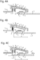
- Figure 4b shows an embodiment wherein the pipe 5 has been inserted up to a point wherein the clamp ring 4 reached what is referred to as the ring insertion position P1, representing an inner most position of the clamp ring 4 within the pipe coupling 1 upon insertion of the pipe 5. Due to initial clamping engagement between the clamp ring 4 and the pipe 5, the clamp ring 4 is displaced in axial direction toward the main tubular body 2, i.e. the abutment surface 11, when the pipe 2 is being inserted. At the ring insertion position P1 the biasing member 6 is in a maximal compressed state and imposes a maximum biasing force on the clamp ring 4 in opposite direction to the displacement of the clamp ring 4 upon insertion of the pipe 5.
- Figure 4c shows an embodiment wherein the pipe 5 has been fully inserted into the main tubular body 2 of the pipe coupling 1, wherein the biasing force imposed by the biasing member 6 caused the clamp ring 4 to move further over the pipe 5 toward the ring locking position P2.
- the biasing member 6 of the present invention facilities movement of the clamp ring 4 over an inserted pipe 5 toward the ring locking position P2.
- the biasing member 6 of the present invention allows an inserted pipe 5 to remain inserted deeper into the pipe coupling 1 as the clamp ring 4 is able to immediately provide sufficient clamping upon insertion of the pipe 5 without requiring pull-out movement of the pipe 5 to intensify clamping action.
Description
- The present invention relates to a pipe coupling, in particular a pipe coupling for making a push fit connection with a pipe.
- Dutch patent application
NL2013426 - International application
WO 03/048625 A1 - US patent publication
US 4,298,220 discloses a pipe joint having a radially displaceable clamp ring located within a cylindrical joint casing to circumvent a pipe passage along which a pipe is to be inserted. The clamp ring is movable between an inner concentric position and an outer eccentric position and provided with a sharp edge around the inner periphery thereof. Upon inserting a pipe into the joint casing, the clamp ring is pushed into the inner concentric position to allow passage of the pipe and, as soon as the pipe is fully inserted into a connected position, the clamp ring is pressed toward the outer eccentric position by a spring, clamping the pipe securely in the connected position by the sharp edge on the inner periphery of the ring. - The present invention aims to provide a pipe coupling, in particular a push fit pipe coupling, wherein the pipe coupling provides improved security, reliability and increased pull-out resistance.
- According to the present invention, a pipe coupling of the type defined in the preamble is provided comprising a main tubular body provided with a pipe receiving bore and a radially deformable clamp ring arranged in the main tubular body for clamping engagement with an inserted pipe. The clamp ring is linearly moveably within the main tubular body in axial direction of the pipe receiving bore between a ring insertion position and a ring locking position, wherein the clamp ring is in wedged engagement with the main tubular body. The pipe coupling further comprises a resilient biasing member arranged within the main tubular body configured for providing positional bias of the clamp ring in the axial direction from the ring insertion position toward the ring locking position. The clamp ring further comprises the biasing member and a grabbing insert for radially grabbing and axially locking an inserted pipe, wherein the grabbing insert is arranged along a circumferential inner surface of the clamp ring. The biasing member is attached to the grabbing insert and comprises one or more circumferentially arranged and axially protruding resilient portions for abutment with the main tubular body.
- The pipe coupling of the present invention allows the clamp ring to be constantly biased toward the ring locking position at which the wedged engagement between the clamp ring and the main tubular body is the strongest. As a result sole reliance on pipe pull-out forces to move the clamp ring to the ring locking position is circumvented. Furthermore, as the clamp ring is forced toward the ring locking position by the biasing member, an inserted pipe can remain deeper in the pipe coupling as sufficient clamping engagement between the clamp ring and the pipe is reached sooner upon insertion of a pipe, i.e. pipe pull-out forces are not needed to intensify the wedged engagement between the clamp ring and the main tubular body. The biasing member thus ensures an immediate pull-out resistance connection upon insertion of a pipe.
- In an exemplary embodiment the biasing member comprises a resilient spring element extending in the axial direction between the main tubular body and the clamp ring, allowing for a continuous and reliable biasing force that ensures the clamp ring is axially biased toward the ring locking position.
- In an embodiment, the biasing member may be attached to the clamp ring such that it resiliently abuts or contacts the main tubular body. In a further embodiment the biasing member may be attached to the main tubular body such that it resiliently abuts or contacts the clamp ring. Any of these embodiments maintain correct placement, orientation and alignment of the biasing member with respect to the main tubular body and the clamp ring.
- In a particular embodiment one or more of the protruding resilient portions, or each of them, may be formed as a leaf spring or coil spring. In a further embodiment the grabbing insert and the plurality of protruding resilient portions may be formed as a single piece (or unitary) component, thereby simplifying manufacturing and reducing cost of the pipe coupling for reliably grabbing an inserted pipe, the grabbing insert and the protruding resilient portions may be made of metal.
- The present invention will be discussed in more detail below, with reference to the attached drawings, in which
-
Figure 1 shows a three dimensional cross section of a pipe coupling according to an embodiment of the present invention; -
Figure 2 shows another cross section of a pipe coupling according to an embodiment of the present invention; -
Figure 3 shows a three dimensional view of a clamp ring as used in the pipe coupling according to an embodiment of the present invention; and -
Figure 4a to 4c each show a schematic view of a pipe coupling configuration upon insertion of a pipe according to an example for understanding the invention but whereinfigures 4a to 4c do not represent the claimed invention as such. - Referring to
Figure 1 andFigure 2 , thepipe coupling 1 of the present invention for push fit insertion of a pipe comprises a maintubular body 2 having apipe receiving bore 3. A radiallydeformable clamp ring 4 is provided and arranged in the maintubular body 2, wherein theclamp ring 4 is configured for clamping engagement with an insertedpipe 5 in operation. Because theclamp ring 4 is radially deformable, a snug and tight clamping engagement with thepipe 5 can be ensured even for small variations of pipe diameters or small mutual orientation variations. Thepipe coupling 1 as shown is capable of connecting an insertedpipe 5 with, for example, a further pipe,adapter piece 5a and the like. - The
clamp ring 4 is linearly moveable with respect to the maintubular body 2 in an axial direction "A" of thepipe receiving bore 3 between a ring insertion position P1 and a ring locking position P2, wherein theclamp ring 4 is in wedged engagement with the maintubular body 2. The wedged engagement provides radial deformation of theclamp ring 4 such that a clamping force can be imposed by theclamp ring 4 on the insertedpipe 5, wherein the wedged engagement intensifies or relaxes through axial displacement of theclamp ring 4 within the maintubular body 2. - For maximum clarity, the phrases "axial direction", "axially" or just "axial" as used in the present application are to be construed as referring to directions substantially parallel to a longitudinal/lengthwise axis 3a of the
pipe receiving bore 3, which will typically coincide with a lengthwise axis of an insertedpipe 5. The phrases "radial direction", "radially" or just "radial" on the other hand are to be construed as referring to directions substantially perpendicular to the axial direction, i.e. the longitudinal/lengthwise axis 3a of thepipe receiving bore 3. - The ring insertion position P1 may be considered to be an innermost position of the
clamp ring 4 within the maintubular body 2 at which the wedged engagement between theclamp ring 4 and the maintubular body 2 is minimal or at a minimum. The ring locking position P2 on the other hand may be considered to be a position of theclamp ring 4 within the maintubular body 2 at which the wedged engagement is at an elevated intensity such that sufficient clamping force is imposed on an insertedpipe 5 by theclamp ring 4 to reliably resist pull-out forces. - Note that the ring locking position P2 is not a fixed absolute position within the main
tubular body 2 as it may vary for different pipe materials, dimensional variations etc. Also, the ring locking position P2 may dependent on pull-out forces F exerted on an insertedpipe 5. That is, when a pull-out force F is exerted on an insertedpipe 5, theclamp ring 4 may move slightly further in axial direction away from the ring insertion position P1 such that the wedged engagement between theclamp ring 4 and the maintubular body 2 intensifies even further. - In an exemplary embodiment, the wedged engagement between the
clamp ring 4 and the maintubular body 2 may be provided through a sloped inner surface 7 of the maintubular body 2 in e.g. sliding engagement with a corresponding slopedouter surface 8 of theclamp ring 4. This embodiment allows wedged engagement between theclamp ring 4 and the maintubular body 2 to intensify when theclamp ring 4 is displaced in axial direction away from the ring insertion position P1 toward the ring locking position P2. In an advantageous embodiment the inner and outersloped surfaces 7, 8 may be conical surfaces for example, so that theclamp ring 4 and its conical outer surface wedges itself against the conical inner surface of thetubular body 2 when theclamp ring 4 moves in axial direction away from the ring insertion position P1. - The
pipe coupling 1 further comprises abiasing member 6, e.g. a resilient biasing member, arranged within the maintubular body 2 and axially biasing theclamp ring 4 from the ring insertion position P1 toward the ring locking position P2. Thebiasing member 6 provides continuous positional bias of theclamp ring 4 toward the ring locking position P2, such that fast and immediate clamping force and pull-out resistance is achieved upon insertion of apipe 5 into thepipe coupling 1. Thebiasing member 6 is thus configured to continuously facilitate and intensify wedged engagement between theclamp ring 4 and thetubular body 2. - The
biasing member 6 comprises a resilient spring element extending in the axial direction between the maintubular body 2 and theclamp ring 4, wherein the resilient spring element allows for a simple but reliable axial biasing force to be imposed on theclamp ring 4 such that continuous positional bias to the ring locking position P2 is provided. - In an exemplary embodiment comprised by the claimed invention, the
biasing member 6 is attached to theclamp ring 4 and resiliently abuts or contacts ("touches") the maintubular body 2. Conversely, in an alternative embodiment which is not part of the claimed present invention, thebiasing member 6 may be attached to the maintubular body 2 and resiliently abut or contact theclamp ring 4. Both embodiments allow and maintain correct placement and alignment of thebiasing member 6 with respect to the maintubular body 2 and theclamp ring 4, ensuring that positional bias toward the ring locking position P2 is guaranteed. As thebiasing member 6 resiliently abuts/contacts either theclamp ring 4 or the maintubular body 2, theclamp ring 4 does not require a particular angular position about the longitudinal/lengthwise axis 3a of thepipe receiving bore 3 in order to reliably provide positional bias toward the ring locking position P2. - Looking at the
clamp ring 4 in further detail,Figure 3 shows a three dimensional view of aclamp ring 4 as used in thepipe coupling 1 according to an embodiment of the present invention. In the embodiment shown, theclamp ring 4 may be cut and have aring opening 4a allowing for radial deformation of theclamp ring 4 such that an insertedpipe 5 can be clamped. In an embodiment theclamp ring 4 may be made of plastic to facilitate resiliency and radial deformation when in wedged engagement with the maintubular body 2. - The
clamp ring 4 further comprises a grabbinginsert 9 for radially grabbing and axially locking an insertedpipe 5, wherein the grabbinginsert 9 is arranged along a circumferential inner surface of theclamp ring 4. In an exemplary embodiment thegrabbing insert 9 comprises a plurality of circumferentially arranged and inwardly protruding/projecting tines, prongs orteeth 9a, thereby contributing to improved pull-out resistance of an insertedpipe 5. In an exemplary embodiment, thegrabbing insert 9 be seen as a ring shaped inlay arranged along an inner circumference or circumferential inner surface of theclamp ring 4. - In the embodiment shown, the
clamp ring 4 comprises thebiasing member 6 and agrabbing insert 9 for radially grabbing and axially locking an insertedpipe 5, wherein thebiasing member 6 is attached to the grabbinginsert 9 and thebiasing member 6 comprises one or more circumferentially arranged and axially protrudingresilient portions 6a for abutment with the maintubular body 2. So in this embodiment theresilient portions 6a protrude or project in axial direction A of theclamp ring 4, i.e. in axial direction of thepipe receiving bore 3, such that the a biasing force on theclamp ring 4 can be generated as theresilient portions 6a abut the maintubular body 2. - The the grabbing
insert 9 and the biasingmember 6 form a single piece (or unitary) component, so that a single material can be used, e.g. metal, to manufacture the grabbinginsert 9 and the biasingmember 6 as a single piece unit. This embodiment also allows theclamp ring 4 to be made of a different material, e.g. plastic, to optimize radial deformation and resiliency, for example, whilst the grabbinginsert 9 with the biasingmember 6 form a single piece component made of another material, e.g. metal, and provided as a ring shaped inlay as mentioned above. - The one or more protruding
resilient portions 6a abut anabutment surface 11 of the maintubular body 2, wherein theabutment surface 11 is arranged normal or substantially perpendicular to the axial direction A, i.e. normal to the lengthwise axis 3a of thepipe receiving bore 3. This embodiment is exemplified inFigure 2 , wherein the protrudingresilient portions 6a axially protrude from theclamp ring 4 in the direction of theabutment surface 11. The one or more protrudingresilient portions 6a may in an embodiment be configured for sliding engagement with theabutment surface 11 to allow the biasingmember 6 to deform, change angular position etc. with respect to theabutment surface 11 when imposing a biasing force. - The
abutment surface 11 may in an exemplary embodiment extend around the lengthwise axis 3a completely, so that theclamp ring 4, and in particular the one or more protrudingresilient portions 6a, can be positioned in any angular position about the lengthwise axis 3a for providing the positional bias toward the ring locking position P2. - In an exemplary embodiment, the one or more protruding
resilient portions 6a each comprise a resilient spring leaf or coil element. A resilient spring leaf or coil element facilitates abutment or contact engagement as well as sliding engagement with theabutment surface 11, so that deformation of the one or more protrudingresilient portions 6a is facilitated when a bias force is imposed. - As mentioned earlier, wedged engagement between the
clamp ring 4 and the maintubular body 2 can be achieved when the maintubular body 2 comprises a sloped inner surface 7 in sliding engagement with a corresponding slopedouter surface 8 of theclamp ring 4, wherein the inner andouter surfaces 7, 8 may be conical surfaces. The sloped inner andouter surfaces 7, 8 allow wedged engagement between theclamp ring 4 and the maintubular body 2 to change in intensity when theclamp ring 4 displaces in axial direction. In the embodiment ofFigure 2 , for example, the sloped inner surface 7 has a larger inner diameter at the ring insertion position P1 than the inner diameter at the ring locking position P2. So when the clamp ring 7 moves toward the ring locking position P2, the wedged engagement intensifies and theclamp ring 4 shrinks in radial direction and clamps the insertedpipe 5. - In an advantageous embodiment, the
clamp ring 4 comprises a slopedouter surface 8 in sliding engagement with a sloped inner surface 7 of the maintubular body 2, wherein the sloped inner surface 7 comprises a radially inward protrudingridge portion 7a. Theridge portion 7a provides a localised accelerated change in clamping engagement for a particular axial displacement of theclamp ring 4. More precisely, theridge portion 7a locally intensifies and accelerates wedged engagement between theclamp ring 4 and the maintubular body 2 over a relatively small axial displacement of theclamp ring 4 as the slopedouter surface 8 of theclamp ring 4 engages with theridge portion 7a. The positional bias imposed by the biasingmember 6 combined with theridge portion 7a thus provides even faster (more instantaneous) pull-out resistance upon insertion of apipe 5 in thepipe coupling 1. - In particular applications it may be desirable that an inserted
pipe 5 is to be adjusted slightly about its lengthwise axis to finalize installation. For that purpose there is provided an embodiment wherein the maintubular body 2 comprises a rotationally arrangedouter ring member 12 in which theclamp ring 4 is linearly moveably in the axial direction and is in wedged engagement therewith. Should readjustment not be sufficient, and an insertedpipe 5 needs to be replaced entirely, then an embodiment is provided wherein theouter ring member 12 is releasably connected to the maintubular body 2, allowing theclamp ring 4 to relax when theouter ring member 12 is disconnected. In an exemplary embodiment theouter ring member 12 and the maintubular body 2 form a releasable bayonet coupling arrangement. Such a bayonet coupling arrangement allows a simple and effective mechanism for turning theouter ring member 12 to a particular angular position at which theouter ring member 12 becomes linearly movable in the axial direction A and removable from the maintubular body 2. Doing so allows theclamp ring 4 to radially enlarge such that clamping forces on an insertedpipe 5 disappear and the insertedpipe 5 is no longer locked within thepipe coupling 1. - Having a releasable connection between a
pipe 5 and thepipe coupling 1 is also possible when theclamp ring 4 is provided with a grabbinginsert 9 having radially inward protrudingtines 9a. Removing theouter ring member 12 in axial direction A from the maintubular body 2 also allows theclamp ring 4 to radially enlarge and as such release thetines 9a from grabbing the insertedpipe 5. - In an advantageous embodiment, the
outer ring member 12, theclamp ring 4 as well as the maintubular body 2 can each be made of a plastic or metal material. Advantageously, to facilitate sufficient resiliency and flexibility for clamping, theclamp ring 4 may be made of a plastic material. Note that theouter ring member 12 and the maintubular body 2 can be made of the same material, such as a plastic or metal material. In an even further embodiment theouter ring member 12, the maintubular body 2 and theclamp ring 4 are made of a plastic material, such as polypropylene. The grabbinginsert 9 with the biasingmember 6 may then be provided as a single piece component made of another material, e.g. metal, and provided as a ring shaped inlay along an inner circumference of theclamp ring 4. Thepipe coupling 1 is then by and large made of plastic allowing cost effective manufacturing whilst providing secure and reliable pipe locking. - In actual use of the
pipe coupling 1 when inserting apipe 5, the maintubular body 2 and theclamp ring 4 interact in a manner as schematically depicted inFigure 4a to 4c . - In
Figure 4a thepipe coupling 1 comprises the maintubular body 2 having thepipe receiving bore 3 and the radiallydeformable clamp ring 4 arranged in the maintubular body 2. Theclamp ring 4 is linearly moveably within the maintubular body 2 in axial direction, i.e. along the longitudinal/lengthwise axis 3a of thepipe receiving bore 3 as depicted inFigure 2 . Theclamp ring 4 is in wedged engagement with the maintubular body 2. The biasingmember 6 is arranged within the maintubular body 2 for providing the axial biasing force on theclamp ring 4, wherein the biasingmember 6 comprises a resilient spring element extending in the axial direction between the maintubular body 2 and theclamp ring 4. The biasingmember 6 may be embodied as a resilient spring leaf or coil element which resiliently abuts/contacts anabutment surface 11 of the maintubular body 2. - In an alternative embodiment, which is not part of the claimed invention, it is of course conceivable that the biasing
member 6 resiliently abuts/contacts anabutment surface 4b of theclamp ring 4. Conversely, the biasingmember 6 can be attached to theclamp ring 4 and resiliently abut/touch the maintubular body 2, e.g. through theabutment surface 11 thereof. Theclamp ring 4 further comprises a grabbinginsert 9 configured to radially grab and axially lock an insertedpipe 5 through a plurality of radially inward protrudingtines 9a circumferentially arranged along theclamp ring 4. - When inserting a
pipe 5 into thepipe coupling 1, at some position within thepipe coupling 1 theclamp ring 4 comes into contact with thepipe 5 due to the radial deformation of theclamp ring 1. This radial deformation is achieved as the biasingmember 6 biases theclamp ring 4 toward the ring locking position P2, hence inducing elevated wedged engagement, which in turn imposes radial shrinkage of theclamp ring 4. In the depicted embodiment, thepipe 5 comes into (frictional) contact with, in this case, the grabbinginsert 9 and in particular the plurality of circumferentially arranged and radially inward protrudingtines 9a. -
Figure 4b shows an embodiment wherein thepipe 5 has been inserted up to a point wherein theclamp ring 4 reached what is referred to as the ring insertion position P1, representing an inner most position of theclamp ring 4 within thepipe coupling 1 upon insertion of thepipe 5. Due to initial clamping engagement between theclamp ring 4 and thepipe 5, theclamp ring 4 is displaced in axial direction toward the maintubular body 2, i.e. theabutment surface 11, when thepipe 2 is being inserted. At the ring insertion position P1 the biasing member
6 is in a maximal compressed state and imposes a maximum biasing force on theclamp ring 4 in opposite direction to the displacement of theclamp ring 4 upon insertion of thepipe 5. In the embodiment ofFigure 4b , theclamp ring 4 has now moved further over thepipe 5 due to the biasing force. Although theclamp ring 4 has reached the ring insertion position P1, so its inner most position within the maintubular body 2, thepipe 5 itself can be inserted further into thepipe receiving bore 3. -
Figure 4c shows an embodiment wherein thepipe 5 has been fully inserted into the maintubular body 2 of thepipe coupling 1, wherein the biasing force imposed by the biasingmember 6 caused theclamp ring 4 to move further over thepipe 5 toward the ring locking position P2. At the ring locking position P2 sufficient radial shrinkage is provided by wedged engagement between the maintubular body 2 and theclamp ring 4, thereby locking the insertedpipe 5 in axial direction by theclamp ring 4, i.e. thetines 9a.
FromFigures 4a to 4c it is seen that the biasingmember 6 of the present invention facilities movement of theclamp ring 4 over an insertedpipe 5 toward the ring locking position P2. This reduces sole reliance on pull-out forces F on an insertedpipe 5 to move theclamp ring 4 to the ring locking position P2 in order to obtain sufficient clamping. Furthermore, the biasingmember 6 of the present invention allows an insertedpipe 5 to remain inserted deeper into thepipe coupling 1 as theclamp ring 4 is able to immediately provide sufficient clamping upon insertion of thepipe 5 without requiring pull-out movement of thepipe 5 to intensify clamping action. - The present invention has been described above with reference to a number of exemplary embodiments as shown in the drawings. Modifications and alternative implementations of some parts or elements are possible, and are included in the scope of protection as defined in the appended claims.
Claims (11)
- A pipe coupling for push fit insertion of a pipe (5), comprising a main tubular body (2) provided with a pipe receiving bore (3) and a radially deformable clamp ring (4) arranged in the main tubular body (2) for clamping engagement with an inserted pipe (5) in operation,
wherein the clamp ring (4) is linearly moveable with respect to the main tubular body (2) in an axial direction (A) of the pipe receiving bore (3) between a ring insertion position (P1) and a ring locking position (P2), and wherein the clamp ring (4) is in wedged engagement with the main tubular body (2), the pipe coupling (1) further comprising
a biasing member (6) arranged within the main tubular body (2) and axially biasing the clamp ring (4) from the ring insertion position (P1) to the ring locking position (P2),
wherein the clamp ring (4) comprises the biasing member (6) and a grabbing insert (9) for radially grabbing and axially locking an inserted pipe (5), wherein the grabbing insert (9) is arranged along a circumferential inner surface of the clamp ring (4), and
wherein the biasing member (6) is attached to the grabbing insert (9) and comprises one or more circumferentially arranged and axially protruding resilient portions (6a) for abutment with the main tubular body (2), wherein the grabbing insert (9) and the biasing member (6) form a single piece component provided as a ring shaped inlay made of a material which is different from a material of the clamp ring (4). - The pipe coupling according to claim 1, wherein the biasing member (6) comprises a resilient spring element extending in the axial direction (A) between the main tubular body (2) and the clamp ring (4).
- The pipe coupling according to claim 1 or 2, wherein the one or more protruding resilient portions (6a) abut an abutment surface (11) of the main tubular body (2) normal to the axial direction (A).
- The pipe coupling according to any one of claims 1-3, wherein the one or more protruding resilient portions (6a) each comprise a resilient spring leaf or coil element.
- The pipe coupling according to any one of claims 1-4, wherein the grabbing insert (9) and the biasing member (6) are made of metal.
- The pipe coupling according to any one of claims 1-5, wherein the grabbing insert (9) comprises a plurality of circumferentially arranged and inwardly protruding tines (9a).
- The pipe coupling according to anyone of claims 1-6, wherein the clamp ring (4) comprises a sloped outer surface (8) in sliding engagement with a sloped inner surface (7) of the main tubular body (2), wherein the sloped inner surface (7) comprises a radially inward protruding ridge portion (7a).
- The pipe coupling according to any one of claims 1-7, wherein the main tubular body (2) comprises a rotationally arranged outer ring member (12), the clamp ring (4) being linearly moveable in the axial direction (A) within the outer ring member (12) and in wedged engagement therewith.
- The pipe coupling according to claim 8, wherein the outer ring member (12) is releasable from the main tubular body (2).
- The pipe coupling according to claim 8 or 9, wherein the outer ring member (12) and the main tubular body (2) form a releasable bayonet coupling arrangement.
- The pipe coupling according to any one of claims 8-10, wherein the outer ring member (12), main tubular body (2), and the clamp ring 4 are made of a plastic material.
Applications Claiming Priority (1)
| Application Number | Priority Date | Filing Date | Title |
|---|---|---|---|
| NL2019193A NL2019193B1 (en) | 2017-07-06 | 2017-07-06 | Pipe coupling |
Publications (2)
| Publication Number | Publication Date |
|---|---|
| EP3425253A1 EP3425253A1 (en) | 2019-01-09 |
| EP3425253B1 true EP3425253B1 (en) | 2019-10-09 |
Family
ID=60202382
Family Applications (1)
| Application Number | Title | Priority Date | Filing Date |
|---|---|---|---|
| EP18181928.5A Active EP3425253B1 (en) | 2017-07-06 | 2018-07-05 | Pipe coupling |
Country Status (2)
| Country | Link |
|---|---|
| EP (1) | EP3425253B1 (en) |
| NL (1) | NL2019193B1 (en) |
Families Citing this family (4)
| Publication number | Priority date | Publication date | Assignee | Title |
|---|---|---|---|---|
| CN113492415A (en) * | 2020-04-02 | 2021-10-12 | 虫极科技(北京)有限公司 | Clamping jaw |
| US11774022B2 (en) | 2020-12-03 | 2023-10-03 | Mueller International, Llc | Pipe fitting with grip ring |
| US11754208B2 (en) | 2020-12-03 | 2023-09-12 | Mueller International, Llc | Pipe fitting with grip ring |
| CA3228388A1 (en) * | 2021-09-15 | 2023-03-23 | Ryan Fairchild Larson | Pipe fitting with grip ring |
Family Cites Families (3)
| Publication number | Priority date | Publication date | Assignee | Title |
|---|---|---|---|---|
| JPS5730545Y2 (en) * | 1978-04-29 | 1982-07-05 | ||
| DE19945721A1 (en) * | 1999-07-16 | 2001-08-02 | Friatec Ag | Plug coupling for pipes is fitted with sealing rings which rest against their inner surfaces, clamping rings being fitted over pipe ends and locking over these being held in place by which fit between flanges on plug |
| KR200269760Y1 (en) * | 2001-12-03 | 2002-03-25 | 김석윤 | Joint For Plumbing |
-
2017
- 2017-07-06 NL NL2019193A patent/NL2019193B1/en not_active IP Right Cessation
-
2018
- 2018-07-05 EP EP18181928.5A patent/EP3425253B1/en active Active
Non-Patent Citations (1)
| Title |
|---|
| None * |
Also Published As
| Publication number | Publication date |
|---|---|
| NL2019193B1 (en) | 2019-01-16 |
| EP3425253A1 (en) | 2019-01-09 |
Similar Documents
| Publication | Publication Date | Title |
|---|---|---|
| EP3425253B1 (en) | Pipe coupling | |
| EP1108176B1 (en) | Pipe coupling | |
| US5064227A (en) | Connector for hoses and the like | |
| RU2477413C1 (en) | Uncoupler for pipe push-fitting | |
| EP3156709A1 (en) | Ferrule assembly for conduit fitting | |
| US9080599B2 (en) | Cable coupling | |
| KR102208942B1 (en) | A connector for connecting to a tube | |
| EP2061985B1 (en) | Hose fitting | |
| WO2009024787A1 (en) | Push-fit pipe fitting system | |
| US6231084B1 (en) | Plug in coupling for pressure fluid | |
| CN114729720A (en) | Pipe joint for receiving, retaining and releasing pipes and method of assembling a pipe joint | |
| US9310006B2 (en) | Hose connector | |
| US5964482A (en) | Connection between a pipe and a molding | |
| EP3256767B1 (en) | A pipe coupling | |
| CN110869144A (en) | Device for removing a circular collar swaged on a cylindrical projection | |
| EP1907744B1 (en) | Coupling between two tubes with separate set-up clamps | |
| GB2607217A (en) | Plumbing fitting | |
| US9976542B2 (en) | Linear telescopic actuator | |
| EP1692425B1 (en) | Quick connect collet retainer with self-centering structure | |
| WO2011001376A1 (en) | Pipe coupling | |
| JPH0633278Y2 (en) | Sleeve for pipe fittings | |
| EP3956596B1 (en) | Hose connector | |
| EP1927807A1 (en) | A quick-release connection device, particularly for pipes and the like | |
| CN209873984U (en) | Installation component with limiting piece | |
| WO2021080914A1 (en) | A clamp device for being secured to a bar |
Legal Events
| Date | Code | Title | Description |
|---|---|---|---|
| PUAI | Public reference made under article 153(3) epc to a published international application that has entered the european phase |
Free format text: ORIGINAL CODE: 0009012 |
|
| STAA | Information on the status of an ep patent application or granted ep patent |
Free format text: STATUS: THE APPLICATION HAS BEEN PUBLISHED |
|
| AK | Designated contracting states |
Kind code of ref document: A1 Designated state(s): AL AT BE BG CH CY CZ DE DK EE ES FI FR GB GR HR HU IE IS IT LI LT LU LV MC MK MT NL NO PL PT RO RS SE SI SK SM TR |
|
| AX | Request for extension of the european patent |
Extension state: BA ME |
|
| STAA | Information on the status of an ep patent application or granted ep patent |
Free format text: STATUS: REQUEST FOR EXAMINATION WAS MADE |
|
| 17P | Request for examination filed |
Effective date: 20190313 |
|
| RBV | Designated contracting states (corrected) |
Designated state(s): AL AT BE BG CH CY CZ DE DK EE ES FI FR GB GR HR HU IE IS IT LI LT LU LV MC MK MT NL NO PL PT RO RS SE SI SK SM TR |
|
| GRAP | Despatch of communication of intention to grant a patent |
Free format text: ORIGINAL CODE: EPIDOSNIGR1 |
|
| STAA | Information on the status of an ep patent application or granted ep patent |
Free format text: STATUS: GRANT OF PATENT IS INTENDED |
|
| INTG | Intention to grant announced |
Effective date: 20190522 |
|
| GRAS | Grant fee paid |
Free format text: ORIGINAL CODE: EPIDOSNIGR3 |
|
| GRAA | (expected) grant |
Free format text: ORIGINAL CODE: 0009210 |
|
| STAA | Information on the status of an ep patent application or granted ep patent |
Free format text: STATUS: THE PATENT HAS BEEN GRANTED |
|
| AK | Designated contracting states |
Kind code of ref document: B1 Designated state(s): AL AT BE BG CH CY CZ DE DK EE ES FI FR GB GR HR HU IE IS IT LI LT LU LV MC MK MT NL NO PL PT RO RS SE SI SK SM TR |
|
| REG | Reference to a national code |
Ref country code: GB Ref legal event code: FG4D |
|
| REG | Reference to a national code |
Ref country code: CH Ref legal event code: EP |
|
| REG | Reference to a national code |
Ref country code: IE Ref legal event code: FG4D |
|
| REG | Reference to a national code |
Ref country code: DE Ref legal event code: R096 Ref document number: 602018000840 Country of ref document: DE |
|
| REG | Reference to a national code |
Ref country code: AT Ref legal event code: REF Ref document number: 1189237 Country of ref document: AT Kind code of ref document: T Effective date: 20191115 |
|
| REG | Reference to a national code |
Ref country code: NL Ref legal event code: FP |
|
| REG | Reference to a national code |
Ref country code: LT Ref legal event code: MG4D |
|
| REG | Reference to a national code |
Ref country code: AT Ref legal event code: MK05 Ref document number: 1189237 Country of ref document: AT Kind code of ref document: T Effective date: 20191009 |
|
| PG25 | Lapsed in a contracting state [announced via postgrant information from national office to epo] |
Ref country code: ES Free format text: LAPSE BECAUSE OF FAILURE TO SUBMIT A TRANSLATION OF THE DESCRIPTION OR TO PAY THE FEE WITHIN THE PRESCRIBED TIME-LIMIT Effective date: 20191009 Ref country code: GR Free format text: LAPSE BECAUSE OF FAILURE TO SUBMIT A TRANSLATION OF THE DESCRIPTION OR TO PAY THE FEE WITHIN THE PRESCRIBED TIME-LIMIT Effective date: 20200110 Ref country code: LV Free format text: LAPSE BECAUSE OF FAILURE TO SUBMIT A TRANSLATION OF THE DESCRIPTION OR TO PAY THE FEE WITHIN THE PRESCRIBED TIME-LIMIT Effective date: 20191009 Ref country code: FI Free format text: LAPSE BECAUSE OF FAILURE TO SUBMIT A TRANSLATION OF THE DESCRIPTION OR TO PAY THE FEE WITHIN THE PRESCRIBED TIME-LIMIT Effective date: 20191009 Ref country code: SE Free format text: LAPSE BECAUSE OF FAILURE TO SUBMIT A TRANSLATION OF THE DESCRIPTION OR TO PAY THE FEE WITHIN THE PRESCRIBED TIME-LIMIT Effective date: 20191009 Ref country code: NO Free format text: LAPSE BECAUSE OF FAILURE TO SUBMIT A TRANSLATION OF THE DESCRIPTION OR TO PAY THE FEE WITHIN THE PRESCRIBED TIME-LIMIT Effective date: 20200109 Ref country code: LT Free format text: LAPSE BECAUSE OF FAILURE TO SUBMIT A TRANSLATION OF THE DESCRIPTION OR TO PAY THE FEE WITHIN THE PRESCRIBED TIME-LIMIT Effective date: 20191009 Ref country code: BG Free format text: LAPSE BECAUSE OF FAILURE TO SUBMIT A TRANSLATION OF THE DESCRIPTION OR TO PAY THE FEE WITHIN THE PRESCRIBED TIME-LIMIT Effective date: 20200109 Ref country code: PL Free format text: LAPSE BECAUSE OF FAILURE TO SUBMIT A TRANSLATION OF THE DESCRIPTION OR TO PAY THE FEE WITHIN THE PRESCRIBED TIME-LIMIT Effective date: 20191009 Ref country code: AT Free format text: LAPSE BECAUSE OF FAILURE TO SUBMIT A TRANSLATION OF THE DESCRIPTION OR TO PAY THE FEE WITHIN THE PRESCRIBED TIME-LIMIT Effective date: 20191009 Ref country code: PT Free format text: LAPSE BECAUSE OF FAILURE TO SUBMIT A TRANSLATION OF THE DESCRIPTION OR TO PAY THE FEE WITHIN THE PRESCRIBED TIME-LIMIT Effective date: 20200210 |
|
| PG25 | Lapsed in a contracting state [announced via postgrant information from national office to epo] |
Ref country code: HR Free format text: LAPSE BECAUSE OF FAILURE TO SUBMIT A TRANSLATION OF THE DESCRIPTION OR TO PAY THE FEE WITHIN THE PRESCRIBED TIME-LIMIT Effective date: 20191009 Ref country code: RS Free format text: LAPSE BECAUSE OF FAILURE TO SUBMIT A TRANSLATION OF THE DESCRIPTION OR TO PAY THE FEE WITHIN THE PRESCRIBED TIME-LIMIT Effective date: 20191009 Ref country code: IS Free format text: LAPSE BECAUSE OF FAILURE TO SUBMIT A TRANSLATION OF THE DESCRIPTION OR TO PAY THE FEE WITHIN THE PRESCRIBED TIME-LIMIT Effective date: 20200224 |
|
| PG25 | Lapsed in a contracting state [announced via postgrant information from national office to epo] |
Ref country code: AL Free format text: LAPSE BECAUSE OF FAILURE TO SUBMIT A TRANSLATION OF THE DESCRIPTION OR TO PAY THE FEE WITHIN THE PRESCRIBED TIME-LIMIT Effective date: 20191009 |
|
| REG | Reference to a national code |
Ref country code: DE Ref legal event code: R097 Ref document number: 602018000840 Country of ref document: DE |
|
| PG2D | Information on lapse in contracting state deleted |
Ref country code: IS |
|
| PG25 | Lapsed in a contracting state [announced via postgrant information from national office to epo] |
Ref country code: CZ Free format text: LAPSE BECAUSE OF FAILURE TO SUBMIT A TRANSLATION OF THE DESCRIPTION OR TO PAY THE FEE WITHIN THE PRESCRIBED TIME-LIMIT Effective date: 20191009 Ref country code: DK Free format text: LAPSE BECAUSE OF FAILURE TO SUBMIT A TRANSLATION OF THE DESCRIPTION OR TO PAY THE FEE WITHIN THE PRESCRIBED TIME-LIMIT Effective date: 20191009 Ref country code: RO Free format text: LAPSE BECAUSE OF FAILURE TO SUBMIT A TRANSLATION OF THE DESCRIPTION OR TO PAY THE FEE WITHIN THE PRESCRIBED TIME-LIMIT Effective date: 20191009 Ref country code: EE Free format text: LAPSE BECAUSE OF FAILURE TO SUBMIT A TRANSLATION OF THE DESCRIPTION OR TO PAY THE FEE WITHIN THE PRESCRIBED TIME-LIMIT Effective date: 20191009 Ref country code: IS Free format text: LAPSE BECAUSE OF FAILURE TO SUBMIT A TRANSLATION OF THE DESCRIPTION OR TO PAY THE FEE WITHIN THE PRESCRIBED TIME-LIMIT Effective date: 20200209 |
|
| PLBE | No opposition filed within time limit |
Free format text: ORIGINAL CODE: 0009261 |
|
| STAA | Information on the status of an ep patent application or granted ep patent |
Free format text: STATUS: NO OPPOSITION FILED WITHIN TIME LIMIT |
|
| PG25 | Lapsed in a contracting state [announced via postgrant information from national office to epo] |
Ref country code: SM Free format text: LAPSE BECAUSE OF FAILURE TO SUBMIT A TRANSLATION OF THE DESCRIPTION OR TO PAY THE FEE WITHIN THE PRESCRIBED TIME-LIMIT Effective date: 20191009 Ref country code: SK Free format text: LAPSE BECAUSE OF FAILURE TO SUBMIT A TRANSLATION OF THE DESCRIPTION OR TO PAY THE FEE WITHIN THE PRESCRIBED TIME-LIMIT Effective date: 20191009 |
|
| 26N | No opposition filed |
Effective date: 20200710 |
|
| PG25 | Lapsed in a contracting state [announced via postgrant information from national office to epo] |
Ref country code: SI Free format text: LAPSE BECAUSE OF FAILURE TO SUBMIT A TRANSLATION OF THE DESCRIPTION OR TO PAY THE FEE WITHIN THE PRESCRIBED TIME-LIMIT Effective date: 20191009 |
|
| PG25 | Lapsed in a contracting state [announced via postgrant information from national office to epo] |
Ref country code: MC Free format text: LAPSE BECAUSE OF FAILURE TO SUBMIT A TRANSLATION OF THE DESCRIPTION OR TO PAY THE FEE WITHIN THE PRESCRIBED TIME-LIMIT Effective date: 20191009 |
|
| PG25 | Lapsed in a contracting state [announced via postgrant information from national office to epo] |
Ref country code: LU Free format text: LAPSE BECAUSE OF NON-PAYMENT OF DUE FEES Effective date: 20200705 Ref country code: IE Free format text: LAPSE BECAUSE OF NON-PAYMENT OF DUE FEES Effective date: 20200705 |
|
| REG | Reference to a national code |
Ref country code: CH Ref legal event code: PL |
|
| PG25 | Lapsed in a contracting state [announced via postgrant information from national office to epo] |
Ref country code: LI Free format text: LAPSE BECAUSE OF NON-PAYMENT OF DUE FEES Effective date: 20210731 Ref country code: CH Free format text: LAPSE BECAUSE OF NON-PAYMENT OF DUE FEES Effective date: 20210731 |
|
| PG25 | Lapsed in a contracting state [announced via postgrant information from national office to epo] |
Ref country code: TR Free format text: LAPSE BECAUSE OF FAILURE TO SUBMIT A TRANSLATION OF THE DESCRIPTION OR TO PAY THE FEE WITHIN THE PRESCRIBED TIME-LIMIT Effective date: 20191009 Ref country code: MT Free format text: LAPSE BECAUSE OF FAILURE TO SUBMIT A TRANSLATION OF THE DESCRIPTION OR TO PAY THE FEE WITHIN THE PRESCRIBED TIME-LIMIT Effective date: 20191009 Ref country code: CY Free format text: LAPSE BECAUSE OF FAILURE TO SUBMIT A TRANSLATION OF THE DESCRIPTION OR TO PAY THE FEE WITHIN THE PRESCRIBED TIME-LIMIT Effective date: 20191009 |
|
| PG25 | Lapsed in a contracting state [announced via postgrant information from national office to epo] |
Ref country code: MK Free format text: LAPSE BECAUSE OF FAILURE TO SUBMIT A TRANSLATION OF THE DESCRIPTION OR TO PAY THE FEE WITHIN THE PRESCRIBED TIME-LIMIT Effective date: 20191009 |
|
| P01 | Opt-out of the competence of the unified patent court (upc) registered |
Effective date: 20230518 |
|
| PGFP | Annual fee paid to national office [announced via postgrant information from national office to epo] |
Ref country code: NL Payment date: 20230726 Year of fee payment: 6 |
|
| PGFP | Annual fee paid to national office [announced via postgrant information from national office to epo] |
Ref country code: IT Payment date: 20230721 Year of fee payment: 6 Ref country code: GB Payment date: 20230725 Year of fee payment: 6 |
|
| PGFP | Annual fee paid to national office [announced via postgrant information from national office to epo] |
Ref country code: FR Payment date: 20230725 Year of fee payment: 6 Ref country code: DE Payment date: 20230726 Year of fee payment: 6 Ref country code: BE Payment date: 20230726 Year of fee payment: 6 |