EP3425240A2 - Réducteur et bogie associé - Google Patents
Réducteur et bogie associé Download PDFInfo
- Publication number
- EP3425240A2 EP3425240A2 EP18181523.4A EP18181523A EP3425240A2 EP 3425240 A2 EP3425240 A2 EP 3425240A2 EP 18181523 A EP18181523 A EP 18181523A EP 3425240 A2 EP3425240 A2 EP 3425240A2
- Authority
- EP
- European Patent Office
- Prior art keywords
- shaft
- gearbox
- gear
- lubricant
- housing
- Prior art date
- Legal status (The legal status is an assumption and is not a legal conclusion. Google has not performed a legal analysis and makes no representation as to the accuracy of the status listed.)
- Granted
Links
Images

Classifications
-
- F—MECHANICAL ENGINEERING; LIGHTING; HEATING; WEAPONS; BLASTING
- F16—ENGINEERING ELEMENTS AND UNITS; GENERAL MEASURES FOR PRODUCING AND MAINTAINING EFFECTIVE FUNCTIONING OF MACHINES OR INSTALLATIONS; THERMAL INSULATION IN GENERAL
- F16H—GEARING
- F16H57/00—General details of gearing
- F16H57/04—Features relating to lubrication or cooling or heating
- F16H57/042—Guidance of lubricant
- F16H57/0421—Guidance of lubricant on or within the casing, e.g. shields or baffles for collecting lubricant, tubes, pipes, grooves, channels or the like
-
- B—PERFORMING OPERATIONS; TRANSPORTING
- B61—RAILWAYS
- B61F—RAIL VEHICLE SUSPENSIONS, e.g. UNDERFRAMES, BOGIES OR ARRANGEMENTS OF WHEEL AXLES; RAIL VEHICLES FOR USE ON TRACKS OF DIFFERENT WIDTH; PREVENTING DERAILING OF RAIL VEHICLES; WHEEL GUARDS, OBSTRUCTION REMOVERS OR THE LIKE FOR RAIL VEHICLES
- B61F5/00—Constructional details of bogies; Connections between bogies and vehicle underframes; Arrangements or devices for adjusting or allowing self-adjustment of wheel axles or bogies when rounding curves
- B61F5/50—Other details
-
- F—MECHANICAL ENGINEERING; LIGHTING; HEATING; WEAPONS; BLASTING
- F16—ENGINEERING ELEMENTS AND UNITS; GENERAL MEASURES FOR PRODUCING AND MAINTAINING EFFECTIVE FUNCTIONING OF MACHINES OR INSTALLATIONS; THERMAL INSULATION IN GENERAL
- F16H—GEARING
- F16H1/00—Toothed gearings for conveying rotary motion
- F16H1/02—Toothed gearings for conveying rotary motion without gears having orbital motion
- F16H1/20—Toothed gearings for conveying rotary motion without gears having orbital motion involving more than two intermeshing members
- F16H1/203—Toothed gearings for conveying rotary motion without gears having orbital motion involving more than two intermeshing members with non-parallel axes
-
- F—MECHANICAL ENGINEERING; LIGHTING; HEATING; WEAPONS; BLASTING
- F16—ENGINEERING ELEMENTS AND UNITS; GENERAL MEASURES FOR PRODUCING AND MAINTAINING EFFECTIVE FUNCTIONING OF MACHINES OR INSTALLATIONS; THERMAL INSULATION IN GENERAL
- F16H—GEARING
- F16H57/00—General details of gearing
- F16H57/02—Gearboxes; Mounting gearing therein
- F16H57/023—Mounting or installation of gears or shafts in the gearboxes, e.g. methods or means for assembly
-
- F—MECHANICAL ENGINEERING; LIGHTING; HEATING; WEAPONS; BLASTING
- F16—ENGINEERING ELEMENTS AND UNITS; GENERAL MEASURES FOR PRODUCING AND MAINTAINING EFFECTIVE FUNCTIONING OF MACHINES OR INSTALLATIONS; THERMAL INSULATION IN GENERAL
- F16H—GEARING
- F16H57/00—General details of gearing
- F16H57/02—Gearboxes; Mounting gearing therein
- F16H57/038—Gearboxes for accommodating bevel gears
-
- F—MECHANICAL ENGINEERING; LIGHTING; HEATING; WEAPONS; BLASTING
- F16—ENGINEERING ELEMENTS AND UNITS; GENERAL MEASURES FOR PRODUCING AND MAINTAINING EFFECTIVE FUNCTIONING OF MACHINES OR INSTALLATIONS; THERMAL INSULATION IN GENERAL
- F16H—GEARING
- F16H57/00—General details of gearing
- F16H57/04—Features relating to lubrication or cooling or heating
- F16H57/045—Lubricant storage reservoirs, e.g. reservoirs in addition to a gear sump for collecting lubricant in the upper part of a gear case
-
- F—MECHANICAL ENGINEERING; LIGHTING; HEATING; WEAPONS; BLASTING
- F16—ENGINEERING ELEMENTS AND UNITS; GENERAL MEASURES FOR PRODUCING AND MAINTAINING EFFECTIVE FUNCTIONING OF MACHINES OR INSTALLATIONS; THERMAL INSULATION IN GENERAL
- F16H—GEARING
- F16H57/00—General details of gearing
- F16H57/04—Features relating to lubrication or cooling or heating
- F16H57/0457—Splash lubrication
-
- F—MECHANICAL ENGINEERING; LIGHTING; HEATING; WEAPONS; BLASTING
- F16—ENGINEERING ELEMENTS AND UNITS; GENERAL MEASURES FOR PRODUCING AND MAINTAINING EFFECTIVE FUNCTIONING OF MACHINES OR INSTALLATIONS; THERMAL INSULATION IN GENERAL
- F16H—GEARING
- F16H57/00—General details of gearing
- F16H57/04—Features relating to lubrication or cooling or heating
- F16H57/048—Type of gearings to be lubricated, cooled or heated
- F16H57/0493—Gearings with spur or bevel gears
- F16H57/0495—Gearings with spur or bevel gears with fixed gear ratio
-
- F—MECHANICAL ENGINEERING; LIGHTING; HEATING; WEAPONS; BLASTING
- F16—ENGINEERING ELEMENTS AND UNITS; GENERAL MEASURES FOR PRODUCING AND MAINTAINING EFFECTIVE FUNCTIONING OF MACHINES OR INSTALLATIONS; THERMAL INSULATION IN GENERAL
- F16H—GEARING
- F16H57/00—General details of gearing
- F16H57/02—Gearboxes; Mounting gearing therein
- F16H2057/02039—Gearboxes for particular applications
- F16H2057/02043—Gearboxes for particular applications for vehicle transmissions
-
- F—MECHANICAL ENGINEERING; LIGHTING; HEATING; WEAPONS; BLASTING
- F16—ENGINEERING ELEMENTS AND UNITS; GENERAL MEASURES FOR PRODUCING AND MAINTAINING EFFECTIVE FUNCTIONING OF MACHINES OR INSTALLATIONS; THERMAL INSULATION IN GENERAL
- F16H—GEARING
- F16H57/00—General details of gearing
- F16H57/02—Gearboxes; Mounting gearing therein
- F16H2057/02086—Measures for reducing size of gearbox, e.g. for creating a more compact transmission casing
Definitions
- the present invention relates to a reducer.
- the present invention also relates to a bogie comprising such a gearbox.
- Reducers are integrated in a large number of mechanical systems, to transmit a movement between two parts rotating at different speeds, that is to say to establish a different transmission ratio of 1 between the two parts.
- such reducers frequently connect an engine to an axle driven by the engine, for example in railway carriages.
- the gearboxes frequently comprise an input shaft, an output shaft and an intermediate axis transmitting a movement of the input shaft to the output shaft, these axes cooperating with each other by gears arranged to establish the transmission ratio other than 1.
- the gears of the gearbox are, in general, lubricated with a liquid such as an oil.
- gearbox in which the input shaft is located at a height greater than that of the output shaft, the output shaft being perpendicular to the input shaft.
- the intermediate shaft is perpendicular to the output shaft and connected thereto by a bevel gear.
- Conical gears are particularly susceptible to friction, and therefore require more efficient lubrication than other types of gears, such as spur gears.
- the gear element carried by the output shaft is immersed in an oil reservoir located in the lower part of a housing housing the gear shafts and gears. So, when the gearbox is in operation, the gear element of the output shaft drives the oil to the bevel gear, which is thus lubricated.
- the oil reserve being located in the lower part of the housing, the oil projected on the walls of the housing is recovered by gravity, which ensures that the oil reserve does not empty completely in operation.
- the reducers of this type are adapted, by their geometry and their size, to certain applications.
- they have a large width in a horizontal plane at the output shaft, and therefore the axle of a railway vehicle bogie in which they would be integrated.
- the subject of the invention is a gearbox for transmitting a movement of a motor to an element driven by the motor, the gearbox comprising a first shaft and a second shaft, one of which is intended to be connected. at the motor and the other is intended to be connected to the element driven by the motor, the gearbox further comprising an intermediate shaft transmitting the movement of the first shaft to the second shaft and a housing defining a chamber, the first shaft and the second shaft each extending at least partially out of the housing, the intermediate shaft being received in the chamber and comprising a first gear member cooperating with the first shaft and a second gear element cooperating with the second shaft.
- the first shaft and the intermediate shaft are arranged at a first height relative to a bottom of the chamber, the second shaft being arranged at a second height relative to the bottom of the chamber, the second height being less than the first height, and in that the reducer comprises a first bubble bath containing a lubricant, the first gear element being at least partially immersed in the first bubble bath.
- the gearbox has a small width in its lower part, while allowing effective lubrication of the gear between the first shaft and the intermediate shaft, although this gear is remote from the bottom of the housing.
- the invention also relates to a railway vehicle engine bogie comprising an axle, a motor and a gearbox configured to transmit a movement of the motor to the axle, the gearbox being as defined above, the first shaft being connected to the motor and the second shaft being connected to the axle.
- a reducer 10 is represented on the figure 1 .
- the gearbox 10 is integrated with a vehicle, such as a railway vehicle.
- the gearbox 10 is part of a bogie engine of the railway vehicle.
- Gear reducer 10 is provided to transmit motion between a vehicle engine and a motor driven member.
- the element driven by the engine is an axle of the bogie.
- the gearbox 10 comprises a first shaft 15, a second shaft 20, an intermediate shaft 25, and a housing 30 delimiting a chamber 32.
- An elevation direction Z is defined for the gearbox 10.
- the elevation direction Z corresponds to a vertical direction when the gearbox 10 is integrated in a bogie and the bogie is operating flat, that is to say disposed on substantially horizontal rails.
- the terms “lower” and “upper”, “above” and “below” are defined in the direction of elevation Z.
- the heights are measured in the direction of elevation Z.
- One of the first shaft 15 and the second shaft 20 is intended to be connected to the motor and the other shaft 15, 20 is intended to be connected to the element driven by the motor.
- the first shaft 15 is connected to the motor and the second shaft 20 is connected to a wheel of the vehicle or a wheel driving device.
- the first shaft 15 is connected to the element driven by the motor and the second shaft 20 is connected to the motor.
- the first shaft 15 extends at least partially out of the housing 30.
- the first shaft 15 has a first end 35 and a second end 40.
- the first shaft 15 extends in a first direction D1 between the first end 35 and the second end 40.
- the first direction D1 is perpendicular to the elevation direction Z.
- the first shaft 15 is, for example, cylindrical with a circular base around a first axis.
- the first axis is confused with the first direction D1.
- the first shaft 15 is disposed at a first height d1 of a bottom 43 of the chamber 32.
- the first height d1 is, for example, measured between the bottom of the chamber 32 and the first axis, in the direction of elevation Z
- bottom is meant the lower bottom wall of the housing defining the chamber 32.
- the first height d1 is, for example, between 450 millimeters (mm) and 550 mm, for example equal to 490 mm.
- the first end 35 is located outside the housing 30.
- the first end 35 is connected to the motor, for example by a gear.
- the second end 40 is accommodated in the chamber 32.
- the second end 40 has or carries a first gear element 45.
- the first gear element 45 is for example a bevel gear.
- the second shaft 20 extends at least partially out of the housing 30.
- the second shaft 20 is connected to an axle or forms part of an axle of a vehicle bogie.
- the second shaft 20 is, for example, a shaft of a bogie axle.
- the second shaft 20 extends in a second direction D2.
- the second direction D2 is substantially perpendicular to the first direction D1 and to the elevation direction Z.
- the second shaft 20 passes through the housing 30 from side to side in the second direction D2.
- the second shaft 20 is, for example, cylindrical with a circular base around a second axis.
- the second shaft 20 is disposed at a second height d2 of the bottom of the chamber 32.
- the second height d2 is strictly less than the first height d1. In other words, if it is considered that the first shaft 15 is located at a first level, the second shaft 20 is disposed at a second level below the first level.
- the second height d2 is measured between the second axis and the bottom of the chamber 32.
- the second height d2 is, for example, between 200 mm and 250 mm, for example equal to 225 mm.
- the difference between the first height d1 and the second height d2 is greater than or equal to 20 cm.
- the second shaft 20 comprises or carries, in addition, a second gear element 50.
- the second gear element 50 is for example a toothed wheel.
- the second gear element 50 is accommodated in the chamber 32.
- the second gear element 50 has, for example, a helical cut. According to one variant, the second gear element 50 has a straight toothing.
- the intermediate shaft 25 is received in the chamber 32.
- the intermediate shaft 25 has a third end 55 and a fourth end 60.
- Each of the third end 55 and the second end 60 is rotatably mounted in the
- the ends 55, 60 of the intermediate shaft 25 are rotatably mounted in the walls of the casing 30 via bearings 65.
- the intermediate shaft 25 extends in a third direction D3.
- the third direction D3 is substantially perpendicular to the first direction D1 and to the elevation direction Z.
- the third direction D3 is thus substantially parallel to the second direction D2.
- the intermediate shaft 25 is cylindrical with a circular base around a third axis.
- the first axis and the third axis are concurrent and coplanar.
- the intermediate shaft 25 is disposed at the first level, that is to say that the intermediate shaft 25 is disposed at the first height d1 of the bottom of the chamber 32.
- the second shaft 20 and the intermediate shaft 25 are superimposed in the direction of elevation Z.
- the intermediate shaft 25 is configured to transmit a movement of the first shaft 15 to the second shaft 20 through the first and second gear elements, for example with a transmission ratio other than 1.
- the intermediate shaft 25 has a third gear element 70 and a fourth gear element 75.
- the third gear member 70 is configured to cooperate with the first shaft 15. In particular, the third gear member 70 meshes with the first gear member 45.
- the third gear element 70 is for example a conical ring.
- the numbers of teeth of the second and third gear elements 45 and 70 are chosen, for example, to obtain a reduction ratio of between 1.5 and 5.
- the third gear element 70 is received in the chamber 32.
- first and third gear members 45 and 70 form a hypoid gear and not a bevel gear, the first and third axes then being perpendicular but non-intersecting.
- the fourth gear element 75 is received in the chamber 32.
- the fourth gear element 75 cooperates with the second shaft 20.
- the fourth gear element 75 meshes with the second gear element 50.
- the fourth gear member 75 is a helical gear.
- the casing 30 is configured to isolate the outside of the casing 30 from the inside of the chamber 32.
- the casing 30 is configured to prevent leakage of lubricant from inside the chamber 32 towards the outside of the casing 30 or the entry of dust from the outside of the housing 30 to the interior of the chamber 32.
- the casing 30 comprises a first sparging tank 80, a reserve tank 85, at least one trough 90, a second sparging tank 95 and a baffle.
- the first sparger pan 80 is configured to contain a lubricant.
- the lubricant is, for example, an oil suitable for lubricating a gear transmission.
- the first sparger pan 80 is configured so that the third gear member 70 is at least partially accommodated in the first sparger pan 80. In other words, when the first spudger tray 80 contains a lubricant, the third spinner gearbox 70 is at least partially immersed in the lubricant contained in the first sparger tray 80.
- the first bubbler 80 has a first volume V1.
- the first volume V1 is between 0.2 liter and 0.6 liter, for example equal to 0.4 liter.
- the first sparger pan 80 is interposed between the third gear member 70 and the second shaft 20 in the elevation direction Z.
- the first sparger tank 80 is delimited by a wall of the casing 30, by a bottom 100 integral with the casing wall 30 and a first peripheral wall 105.
- the bottom 100 is interposed between the second shaft 20 and the third gear element 70 in the direction of elevation Z.
- the first peripheral wall 105 surrounds the first bubble bath 80 at least partially in a plane perpendicular to the elevation direction Z.
- the first peripheral wall 105 then delimits the first bubble bath 80 in a plane perpendicular to the elevation direction Z.
- the first peripheral wall 105 is interposed between the third gear element 70 and the fourth gear element 75 in the third direction D3.
- the tank 85 is configured to contain lubricant.
- the reservoir 85 is interposed between the first sparger tank 80 and the fourth gear element 75 in the third direction D3.
- the storage tank 85 is separated from the first bubble tank 80 by the first peripheral wall 105.
- the storage tank 85 is delimited, in the third direction D3, by the first peripheral wall 105 and by a second peripheral wall 110.
- the reservoir 85 is in fluid communication with the first sparger pan 80, i.e., the spill tray 85 is configured so that the lubricant can flow between the first sparger pan 80 and the spill container. 85.
- the reservoir 85 is in fluid communication with the first sparger tank 80 through at least one conduit extending through the first septum
- the reservoir 85 is in fluid communication with the first sparger tank 80 through at least two conduits.
- the reservoir 85 surrounds the first sparger tank 80 in a plane perpendicular to the elevation direction Z, at least partially.
- the reserve tank 85 has a second volume V2.
- the second volume V2 is strictly greater than the first volume V1.
- the second volume V2 is between 0.6 liter and 1 liter, for example equal to 0.8 liter.
- the bottom of the storage tank 85 is located at a height greater than the height of the bottom 100 of the bubble tray 80 relative to the bottom of the chamber.
- Each duct extends along a driving axis.
- An angle between the two driving axes is greater than or equal to 60 °.
- the angle is equal to 90 °, within 10 °.
- a first duct is formed in a portion of the first peripheral wall 105 perpendicular to the third direction D3 and extends along a driving axis parallel to the third direction D3.
- a second duct is then formed in a portion of the first peripheral wall 105 parallel to the third direction D3 and extends along a driving axis perpendicular to the third direction D3.
- Each conduit has a diameter. At least one of these diameters is less than or equal to 20 mm. For example, each duct has a diameter less than or equal to 20 mm.
- the first sparger pan 80 is configured to supply lubricant to the second spill tray 95 by overflow.
- the first sparger tank 80 and the reserve tank 85 are configured to supply lubricant to the second sparger tank 95 by overflow.
- the first sparger pan 80 and the sparger tank 85 are configured so that any excess lubricant in the first sparger tank 80 and the sparger tank 85 spills into the second sparger tank 95. .
- the second peripheral wall 110 defines an opening of the housing 30 through which the second gear element 50 passes.
- an excess of lubricant in the first sparger tank 80 and the reserve tank 85 is discharged into the lower part of the casing 30. over the second peripheral wall 110.
- Each chute 90 is configured to collect the lubricant sprayed on the walls of the housing 30 during the rotation of the first shaft 15 and the intermediate shaft 25.
- Each chute 90 is configured to transmit the collected lubricant to the first tank of
- at least one chute 90 is configured to transmit the collected lubricant to the tank 85, the lubricant then reaching the first bubble tank 80 through the conduit.
- Each chute 90 is formed in a wall of the casing 30.
- the second sparger pan 95 is configured to contain lubricant.
- the second gear element 50 is at least partially immersed in the lubricant contained in the second sparger tank 95.
- the second sparger tank 95 has a volume of between 4 liters and 6 liters. liters, for example equal to 5 liters.
- the second sparger tank 95 is located in the lowest part of the chamber 32.
- the first height d1 and the second height d2 are measured from the bottom of the second sparger tank 95, i.e. the bottom 43 of the second bubble tray forms at least a portion of the bottom of the chamber.
- the deflector is interposed between the third gear element 70 and the housing walls 30.
- the deflector at least partially envelops the third gear element 70.
- the deflector is attached to the walls of the housing 30.
- the deflector is configured to collect at least a portion of the lubricant sprayed by the third gear member 70 upon rotation of the intermediate shaft 25.
- the deflector is configured to transmit the collected lubricant to the first sparger tank 80.
- the baffle is located above the first sparger pan 80.
- the deflector comprises a cylindrical wall at least partially surrounding the third gear element 70 in a plane perpendicular to the third direction D3.
- the deflector comprises a disk perpendicular to the third direction D3 and interposed between the third gear element 70 and the fourth gear element 75.
- the deflector is, for example, made of a metal such as steel.
- the sparger tank 80 allows good lubrication of the bevel gear between the first shaft 15 and the intermediate shaft 25.
- the sparger tank 80 enables the bevel gear to be placed in the upper part of the gearbox 10 instead of the bottom part. It is therefore possible to place the intermediate shaft 25 at a height greater than the height of the second shaft, and thus to limit the space requirement in the lower part of the gearbox 10.
- the lubricant contained in the storage tank 85 is less affected by the movement of the third gear element 70 than the first sparger tank 80.
- reserve tank 85 because of its large capacity, forms a buffer zone which makes it possible to ensure efficient replenishment by lubricating the bubbler 80.
- the angle between the driving axes of the different ducts makes it possible to prevent the disturbances caused by the lubricant contained in the first bubble bath by the rotation of the third gear element 70 against the arrival of lubricant. from the storage tank 85. In fact, if these disturbances limit the arrival by one of the ducts, the angle is large enough so that the other duct is not affected. Thus, the supply of lubricant to the sparger tank 80 is more efficient, which makes the reducer 10 more reliable.
- a duct diameter of less than or equal to 25 mm also limits the propagation of disturbances from the first sparger tank 80 to the storage tank 85, while ensuring a sufficient lubricant start.
- the baffle also contributes to a better supply of lubricant to the spinner tray 80, since it collects a large portion of the lubricant that would otherwise have been sprayed onto the crankcase walls and could fall back into the second sparger tank 95. Lubrication of the bevel gear between the first shaft 15 and the intermediate shaft 25 is improved and the gear 10 is more reliable.
Landscapes
- Engineering & Computer Science (AREA)
- General Engineering & Computer Science (AREA)
- Mechanical Engineering (AREA)
- General Details Of Gearings (AREA)
Abstract
Description
- La présente invention concerne un réducteur. La présente invention concerne également un bogie comprenant un tel réducteur.
- Des réducteurs sont intégrés dans un grand nombre de systèmes mécaniques, pour transmettre un mouvement entre deux pièces tournant à des vitesses différentes, c'est-à-dire pour établir un rapport de transmission différent de 1 entre les deux pièces. En particulier, de tels réducteurs relient fréquemment un moteur à un essieu entraîné par le moteur, par exemple dans des voitures de véhicules ferroviaires.
- Les réducteurs comprennent fréquemment un axe d'entrée, un axe de sortie et un axe intermédiaire transmettant un mouvement de l'axe d'entré à l'axe de sortie, ces axes coopérant les uns avec les autres par des engrenages agencés pour établir le rapport de transmission différent de 1. Afin d'assurer une transmission d'énergie aussi efficace que possible, les engrenages du réducteur sont, en général, lubrifiés avec un liquide tel qu'une huile.
- Cependant, de nombreuses contraintes géométriques pèsent sur les réducteurs. Par exemple, l'encombrement des autres éléments du système mécanique dans lequel le réducteur est intégré impose fréquemment que les axes d'entrée et de sortie soient perpendiculaires l'un à l'autre, ou que les axes d'entrée et de sortie soient disposés à des hauteurs différentes.
- Il est connu du document
FR 2 106 978 A5 - Il est également connu un réducteur dans lequel l'arbre d'entrée est situé à une hauteur supérieure à celle de l'arbre de sortie, l'arbre de sortie étant perpendiculaire à l'arbre d'entrée. L'arbre intermédiaire est perpendiculaire à l'arbre de sortie et relié à celui-ci par un engrenage conique. Les engrenages coniques sont particulièrement susceptibles à l'apparition de frottements, et requièrent donc une lubrification plus efficace que d'autres types d'engrenages, tels que les engrenages droits.
- Afin d'assurer une lubrification efficace de l'engrenage conique, l'élément d'engrenage porté par l'arbre de sortie baigne dans une réserve d'huile située dans la partie inférieure d'un carter logeant les arbres et les engrenages du réducteur. Ainsi, lorsque le réducteur est en fonctionnement, l'élément d'engrenage de l'arbre de sortie entraine l'huile jusqu'à l'engrenage conique, qui est ainsi lubrifié.
- La réserve d'huile étant située dans la partie inférieure du carter, l'huile projetée sur les parois du carter est récupérée par gravité, ce qui permet d'assurer que la réserve d'huile ne se vide pas complètement en fonctionnement.
- Cependant, les réducteurs de ce type ne sont adaptés, de par leur géométrie et leur encombrement, qu'à certaines applications. En particulier, ils présentent une largeur importante dans un plan horizontal au niveau de l'arbre de sortie, et donc de l'essieu d'un bogie de véhicule ferroviaire dans lequel ils seraient intégrés.
- Il existe donc un besoin pour un réducteur présentant, dans sa partie basse, une un encombrement réduit par rapport aux réducteurs de l'état de la technique.
- A cet effet, l'invention a pour objet un réducteur pour la transmission d'un mouvement d'un moteur à un élément entraîné par le moteur, le réducteur comportant un premier arbre et un deuxième arbre dont l'un est destiné à être relié au moteur et l'autre est destiné à être relié à l'élément entraîné par le moteur, le réducteur comportant, en outre, un arbre intermédiaire transmettant le mouvement du premier arbre au deuxième arbre et un carter délimitant une chambre, le premier arbre et le deuxième arbre s'étendant chacun au moins partiellement hors du carter, l'arbre intermédiaire étant accueilli dans la chambre et comprenant un premier élément d'engrenage coopérant avec le premier arbre et un deuxième élément d'engrenage coopérant avec le deuxième arbre.
- Le premier arbre et l'arbre intermédiaire sont disposés à une première hauteur par rapport à un fond de la chambre, le deuxième arbre étant disposé à une deuxième hauteur par rapport au fond de la chambre, la deuxième hauteur étant inférieure à la première hauteur, et en ce que le réducteur comporte un premier bac de barbotage contenant un lubrifiant, le premier élément d'engrenage étant au moins partiellement immergé dans le premier bac de barbotage.
- Grâce à l'invention, le réducteur présente une largeur faible dans sa partie basse, tout en permettant une lubrification efficace de l'engrenage entre le premier arbre et l'arbre intermédiaire, bien que cet engrenage soit éloigné du fond du carter.
- Selon d'autres aspects avantageux de l'invention, le réducteur comprend une ou plusieurs des caractéristiques suivantes, prises isolément ou suivant toutes les combinaisons techniquement possibles :
- Le premier arbre et le deuxième arbre s'étendent dans des directions sensiblement perpendiculaires l'une à rapport à l'autre, l'arbre intermédiaire s'étendant selon une direction sensiblement parallèle à celle du deuxième arbre.
- Le premier élément d'engrenage est une couronne conique engrenant sur un pignon conique du premier arbre.
- Le carter comporte un bac de réserve en communication fluidique avec le premier bac de barbotage et contenant du lubrifiant.
- Le bac de réserve est en communication fluidique avec le premier bac de barbotage à travers au moins deux conduits s'étendant chacun selon un axe de conduite, l'angle entre les deux axes de conduite étant supérieur ou égal à 60 degrés.
- Le bac de réserve est en communication fluidique avec le premier bac de barbotage à travers au moins un conduit, le conduit présentant un diamètre inférieur ou égal à 20 millimètres.
- Le carter comporte au moins une goulotte configurée pour recueillir le lubrifiant projeté sur les parois du carter par la rotation du premier arbre et de l'arbre intermédiaire et pour transmettre le lubrifiant recueilli au premier bac de barbotage.
- Le deuxième arbre comporte un troisième élément d'engrenage engrenant sur le deuxième élément d'engrenage, le réducteur comportant un deuxième bac de barbotage contenant du lubrifiant et dans lequel le troisième élément d'engrenage est au moins partiellement immergé, le premier bac de barbotage étant configuré pour alimenter en lubrifiant le deuxième bac de barbotage par débordement.
- Le réducteur comporte, en outre, un déflecteur interposé entre le premier élément d'engrenage et les parois du carter, le déflecteur entourant au moins partiellement le premier élément d'engrenage et étant configuré pour recueillir au moins une partie du lubrifiant projeté par le premier élément d'engrenage lors de la rotation de l'arbre intermédiaire et pour transmettre le lubrifiant recueilli au premier bac de barbotage.
- L'invention a également pour objet un bogie moteur de véhicule ferroviaire comportant un essieu, un moteur et un réducteur configuré pour transmettre un mouvement du moteur à l'essieu, le réducteur étant tel que défini ci-dessus, le premier arbre étant relié au moteur et le deuxième arbre étant relié à l'essieu.
- D'autres aspects et avantages de l'invention apparaîtront à la lecture de la description qui va suivre, donnée uniquement à titre d'exemple non limitatif, et faite en référence aux dessins annexés, sur lesquels :
- la
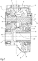
figure 1 est une vue en coupe dans un plan vertical d'un exemple de réducteur selon l'invention, et - la
figure 2 est une vue d'une coupe du réducteur selon le plan II-II de lafigure 1 . - Un réducteur 10 est représenté sur la
figure 1 . Le réducteur 10 est intégré à un véhicule, tel qu'un véhicule ferroviaire. Par exemple, le réducteur 10 fait partie d'un bogie moteur du véhicule ferroviaire. - Le réducteur 10 est prévu pour transmettre un mouvement entre un moteur du véhicule et un élément entraîné par le moteur. Par exemple, l'élément entraîné par le moteur est un essieu du bogie.
- Le réducteur 10 comporte un premier arbre 15, un deuxième arbre 20, un arbre intermédiaire 25, et un carter 30 délimitant une chambre 32.
- Une direction d'élévation Z est définie pour le réducteur 10. La direction d'élévation Z correspond à une direction verticale lorsque le réducteur 10 est intégré dans un bogie et que le bogie est en fonctionnement à plat, c'est-à-dire disposé sur des rails sensiblement horizontaux. On définit les termes « inférieur » et « supérieur », « au-dessus », « en dessous » selon la direction d'élévation Z. Les hauteurs sont mesurées selon la direction d'élévation Z.
- Un arbre parmi le premier arbre 15 et le deuxième arbre 20 est destiné à être relié au moteur et l'autre arbre 15, 20 est destiné à être relié à l'élément entrainé par le moteur.
- Selon l'exemple de la
figure 1 , le premier arbre 15 est relié au moteur et le deuxième arbre 20 est relié à une roue du véhicule ou à un dispositif d'entraînement de la roue. Selon une variante, le premier arbre 15 est relié à l'élément entrainé par le moteur et le deuxième arbre 20 est relié au moteur. - Le premier arbre 15 s'étend au moins partiellement hors du carter 30. Le premier arbre 15 présente une première extrémité 35 et une deuxième extrémité 40.
- Le premier arbre 15 s'étend selon une première direction D1 entre la première extrémité 35 et la deuxième extrémité 40. La première direction D1 est perpendiculaire à la direction d'élévation Z.
- Le premier arbre 15 est, par exemple, cylindrique à base circulaire autour d'un premier axe. Le premier axe est confondu avec la première direction D1.
- Le premier arbre 15 est disposé à une première hauteur d1 d'un fond 43 de la chambre 32. La première hauteur d1 est, par exemple, mesurée entre le fond de la chambre 32 et le premier axe, selon la direction d'élévation Z. Par fond, on entend la paroi inférieure la plus basse du carter délimitant la chambre 32.
- La première hauteur d1 est, par exemple, comprise entre 450 millimètres (mm) et 550 mm, par exemple égale à 490 mm.
- La première extrémité 35 est située à l'extérieur du carter 30. La première extrémité 35 est reliée au moteur, par exemple par un engrenage.
- La deuxième extrémité 40 est accueillie dans la chambre 32. La deuxième extrémité 40 comporte ou porte un premier élément d'engrenage 45.
- Le premier élément d'engrenage 45 est par exemple un pignon conique.
- Le deuxième arbre 20 s'étend au moins partiellement hors du carter 30. Le deuxième arbre 20 est relié à un essieu ou forme une partie de l'un essieu d'un bogie de véhicule. Le deuxième arbre 20 est, par exemple, un arbre d'un essieu de bogie.
- Le deuxième arbre 20 s'étend selon une deuxième direction D2. La deuxième direction D2 est sensiblement perpendiculaire à la première direction D1 et à la direction d'élévation Z.
- Il est entendu par « sensiblement perpendiculaire » qu'un angle entre les directions considérées est égal à 90°, à 10° près.
- Il est entendu par « sensiblement parallèle » qu'un angle entre les directions considérées est égal à 0°, à 10° près.
- Selon l'exemple de la
figure 2 , le deuxième arbre 20 traverse le carter 30 de part en part selon la deuxième direction D2. - Le deuxième arbre 20 est, par exemple, cylindrique à base circulaire autour d'un deuxième axe.
- Le deuxième arbre 20 est disposé à une deuxième hauteur d2 du fond de la chambre 32. La deuxième hauteur d2 est strictement inférieure à la première hauteur d1. En d'autres termes, si l'on considère que le premier arbre 15 est situé à un premier niveau, le deuxième arbre 20 est disposé à un deuxième niveau inférieur au premier niveau. La deuxième hauteur d2 est mesurée entre le deuxième axe et le fond de la chambre 32. La deuxième hauteur d2 est par exemple, comprise entre 200 mm et 250 mm, par exemple égale à 225mm. La différence entre la première hauteur d1 et la deuxième hauteur d2 est supérieure ou égale à 20 cm.
- Le deuxième arbre 20 comporte ou porte, en outre, un deuxième élément d'engrenage 50.
- Le deuxième élément d'engrenage 50 est par exemple une roue dentée. Le deuxième élément d'engrenage 50 est accueilli dans la chambre 32.
- Le deuxième élément d'engrenage 50 présente, par exemple, une denture hélicoïdale. Selon une variante, le deuxième élément d'engrenage 50 présente une denture droite.
- L'arbre intermédiaire 25 est accueilli dans la chambre 32. Par exemple, l'arbre intermédiaire 25 présente une troisième extrémité 55 et une quatrième extrémité 60. Chacune de la troisième extrémité 55 et de la deuxième extrémité 60 est montée libre en rotation dans les parois du carter 30. Selon un mode de réalisation, les extrémités 55, 60 de l'arbre intermédiaire 25 sont montées libres en rotation dans les parois du carter 30 via des roulements 65.
- L'arbre intermédiaire 25 s'étend selon une troisième direction D3. La troisième direction D3 est sensiblement perpendiculaire à la première direction D1 et à la direction d'élévation Z. La troisième direction D3 est ainsi sensiblement parallèle à la deuxième direction D2.
- Selon l'exemple de la
figure 1 , l'arbre intermédiaire 25 est cylindrique à base circulaire autour d'un troisième axe. Le premier axe et le troisième axe sont concourants et coplanaires. - Selon cet exemple, l'arbre intermédiaire 25 est disposé au premier niveau, c'est-à-dire que l'arbre intermédiaire 25 est disposé à la première hauteur d1 du fond de la chambre 32.
- Le deuxième arbre 20 et l'arbre intermédiaire 25 sont superposés selon la direction d'élévation Z.
- L'arbre intermédiaire 25 est configuré pour transmettre un mouvement du premier arbre 15 au deuxième arbre 20 par l'intermédiaire des premier et deuxième éléments d'engrenage, par exemple avec un rapport de transmission différent de 1.
- L'arbre intermédiaire 25 comporte un troisième élément d'engrenage 70 et un quatrième élément d'engrenage 75.
- Le troisième élément d'engrenage 70 est configuré pour coopérer avec le premier arbre 15. En particulier, le troisième élément d'engrenage 70 engrène sur le premier élément d'engrenage 45.
- Le troisième élément d'engrenage 70 est par exemple une couronne conique.
- Les nombres de dents des deuxième et troisième éléments d'engrenage 45 et 70 sont choisis, par exemple, pour obtenir un rapport de réduction compris entre 1,5 et 5.
- Le troisième élément d'engrenage 70 est accueilli dans la chambre 32.
- Selon une variante, les premier et troisième éléments d'engrenage 45 et 70 forment un engrenage hypoïde et non un engrenage conique, le premier et le troisième axe étant alors perpendiculaires mais non concourants.
- Le quatrième élément d'engrenage 75 est accueilli dans la chambre 32. Le quatrième élément d'engrenage 75 coopère avec le deuxième arbre 20. En particulier, le quatrième élément d'engrenage 75 engrène sur le deuxième élément d'engrenage 50. Selon un mode de réalisation, le quatrième élément d'engrenage 75 est un pignon à denture hélicoïdale.
- Le carter 30 est configuré pour isoler l'extérieur du carter 30 de l'intérieur de la chambre 32. En particulier, le carter 30 est configuré pour éviter une fuite de lubrifiant depuis l'intérieur de la chambre 32 vers l'extérieur du carter 30 ou l'entrée de poussières depuis l'extérieur du carter 30 jusqu'à l'intérieur de la chambre 32.
- Le carter 30 comporte un premier bac de barbotage 80, un bac de réserve 85, au moins une goulotte 90, un deuxième bac de barbotage 95 et un déflecteur.
- Le premier bac de barbotage 80 est configuré pour contenir un lubrifiant. Le lubrifiant est, par exemple, une huile adaptée à la lubrification d'une transmission par engrenage. Le premier bac de barbotage 80 est configuré pour que le troisième élément d'engrenage 70 soit au moins partiellement accueilli dans le premier bac de barbotage 80. En d'autres termes, lorsque le premier bac de barbotage 80 contient un lubrifiant, le troisième élément d'engrenage 70 est au moins partiellement immergé dans le lubrifiant contenu dans le premier bac de barbotage 80.
- Le premier bac de barbotage 80 présente un premier volume V1. Le premier volume V1 est compris entre 0,2 litre et 0,6 litre, par exemple égal à 0,4 litre.
- Le premier bac de barbotage 80 est interposé entre le troisième élément d'engrenage 70 et le deuxième arbre 20 selon la direction d'élévation Z.
- Selon l'exemple de la
figure 2 , le premier bac de barbotage 80 est délimité par une paroi du carter 30, par un fond 100 venu de matière avec la paroi de carter 30 et par une première cloison périphérique 105. - Le fond 100 est interposé entre le deuxième arbre 20 et le troisième élément d'engrenage 70 selon la direction d'élévation Z.
- La première cloison périphérique 105 entoure le premier bac de barbotage 80 au moins partiellement dans un plan perpendiculaire à la direction d'élévation Z. La première cloison périphérique 105 délimite alors le premier bac de barbotage 80 dans un plan perpendiculaire à la direction d'élévation Z.
- La première cloison périphérique 105 est interposée entre le troisième élément d'engrenage 70 et le quatrième élément d'engrenage 75 selon la troisième direction D3.
- Le bac de réserve 85 est configuré pour contenir du lubrifiant.
- Le bac de réserve 85 est interposé entre le premier bac de barbotage 80 et le quatrième élément d'engrenage 75 selon la troisième direction D3. Le bac de réserve 85 est séparé du premier bac de barbotage 80 par la première cloison périphérique 105. Selon l'exemple de la
figure 2 , le bac de réserve 85 est délimité, selon la troisième direction D3, par la première cloison périphérique 105 et par une deuxième cloison périphérique 110. - Le bac de réserve 85 est en communication fluidique avec le premier bac de barbotage 80, c'est-à-dire que le bac de réserve 85 est configuré pour que le lubrifiant puisse circuler entre le premier bac de barbotage 80 et le bac de réserve 85.
- Le bac de réserve 85 est en communication fluidique avec le premier bac de barbotage 80 à travers au moins un conduit s'étendant à travers la première cloison périphérique 105. Par exemple, le bac de réserve 85 est en communication fluidique avec le premier bac de barbotage 80 à travers au moins deux conduits.
- Le bac de réserve 85 entoure le premier bac de barbotage 80 dans un plan perpendiculaire à la direction d'élévation Z, au moins partiellement.
- Le bac de réserve 85 présente un deuxième volume V2. Le deuxième volume V2 est strictement supérieur au premier volume V1. Le deuxième volume V2 est compris entre 0,6 litre et 1 litre, par exemple égal à 0,8 litre.
- Le fond du bac de réserve 85 est situé à une hauteur supérieure par rapport à la hauteur du fond 100 du bac de barbotage 80 par rapport au fond de la chambre.
- Chaque conduit s'étend selon un axe de conduite.
- Un angle entre les deux axes de conduite est supérieur ou égal à 60°. Par exemple, l'angle est égal à 90°, à 10° près.
- Selon un mode de réalisation, un premier conduit est ménagé dans une portion de la première cloison périphérique 105 perpendiculaire à la troisième direction D3 et s'étend selon un axe de conduite parallèle à la troisième direction D3. Un deuxième conduit est alors ménagé dans une portion de la première cloison périphérique 105 parallèle à la troisième direction D3 et s'étend selon un axe de conduite perpendiculaire à la troisième direction D3.
- Chaque conduit présente un diamètre. Au moins un de ces diamètres est inférieur ou égal à 20 mm. Par exemple, chaque conduit présente un diamètre inférieur ou égal à 20 mm.
- Le premier bac de barbotage 80 est configuré pour alimenter en lubrifiant le deuxième bac de barbotage 95 par débordement. Selon un mode de réalisation, le premier bac de barbotage 80 et le bac de réserve 85 sont configurés pour alimenter en lubrifiant le deuxième bac de barbotage 95 par débordement. En d'autres termes, le premier bac de barbotage 80 et le bac de réserve 85 sont configurés pour qu'un excès éventuel de lubrifiant dans le premier bac de barbotage 80 et le bac de réserve 85 se déverse dans le deuxième bac de barbotage 95.
- Selon l'exemple de la
figure 2 , la deuxième cloison périphérique 110 délimite une ouverture du carter 30 traversée par le deuxième élément d'engrenage 50. Ainsi, un excès de lubrifiant dans le premier bac de barbotage 80 et le bac de réserve 85 se déverse dans la partie inférieure du carter 30 par-dessus la deuxième cloison périphérique 110. - Chaque goulotte 90 est configurée pour recueillir le lubrifiant projeté sur les parois du carter 30 lors de la rotation du premier arbre 15 et de l'arbre intermédiaire 25. Chaque goulotte 90 est configurée pour transmettre le lubrifiant recueilli au premier bac de barbotage 80. Par exemple, au moins une goulotte 90 est configurée pour transmettre le lubrifiant recueilli au bac de réserve 85, le lubrifiant atteignant ensuite le premier bac de barbotage 80 à travers le conduit.
- Chaque goulotte 90 est ménagée dans une paroi du carter 30.
- Le deuxième bac de barbotage 95 est configuré pour contenir du lubrifiant. Lorsque le deuxième bac de barbotage 95 contient du lubrifiant, le deuxième élément d'engrenage 50 est au moins partiellement immergé dans le lubrifiant contenu dans le deuxième bac de barbotage 95. Le deuxième bac de barbotage 95 présente un volume compris entre 4 litres et 6 litres, par exemple égal à 5 litres.
- Le deuxième bac de barbotage 95 est situé dans la partie la plus basse de la chambre 32. La première hauteur d1 et la deuxième hauteur d2 sont mesurées à partir du fond du deuxième bac de barbotage 95, c'est-à-dire que le fond 43 du deuxième bac de barbotage forme au moins une partie du fond de la chambre.
- Le déflecteur est interposé entre le troisième élément d'engrenage 70 et les parois du carter 30. Par exemple, le déflecteur enveloppe au moins partiellement le troisième élément d'engrenage 70.
- Le déflecteur est fixé aux parois du carter 30.
- Le déflecteur est configuré pour recueillir au moins une partie du lubrifiant projeté par le troisième élément d'engrenage 70 lors de la rotation de l'arbre intermédiaire 25.
- Le déflecteur est configuré pour transmettre le lubrifiant recueilli au premier bac de barbotage 80. Par exemple, le déflecteur est situé au-dessus du premier bac de barbotage 80.
- Selon un mode de réalisation, le déflecteur comprend une paroi cylindrique entourant au moins partiellement le troisième élément d'engrenage 70 dans un plan perpendiculaire à la troisième direction D3. Selon une variante, le déflecteur comporte un disque perpendiculaire à la troisième direction D3 et interposé entre le troisième élément d'engrenage 70 et le quatrième élément d'engrenage 75.
- Le déflecteur est, par exemple, réalisé en un métal tel que l'acier.
- L'utilisation du bac de barbotage 80 permet une bonne lubrification de l'engrenage conique entre le premier arbre 15 et l'arbre intermédiaire 25. Ainsi, le bac de barbotage 80 permet de placer l'engrenage conique dans la partie supérieure du réducteur 10 au lieu de la partie inférieure. Il est donc possible de placer l'arbre intermédiaire 25 à une hauteur supérieure à la hauteur du deuxième arbre, et donc de limiter l'encombrement dans la partie basse du réducteur 10.
- Le lubrifiant contenu dans le bac de réserve 85 est moins affecté par le mouvement du troisième élément d'engrenage 70 que le premier bac de barbotage 80. Le bac de réserve 85, de par sa grande contenance, forme une zone tampon qui permet d'assurer la réalimentation efficace en lubrifiant du bac de barbotage 80.
- L'angle entre les axes de conduite des différents conduits permet d'éviter que les perturbations causées, dans le lubrifiant contenu dans le premier bac de barbotage, par la rotation du troisième élément d'engrenage 70 s'opposent à l'arrivée de lubrifiant depuis le bac de réserve 85. De fait, si ces perturbations limitent l'arrivée par l'un des conduits, l'angle est assez important pour que l'autre conduit ne soit pas affecté. Ainsi, l'alimentation en lubrifiant du bac de barbotage 80 est plus efficace, ce qui rend donc plus fiable le réducteur 10.
- Par ailleurs, un diamètre de conduit inférieur ou égal à 25 mm limite également la propagation des perturbations depuis le premier bac de barbotage 80 jusqu'au bac de réserve 85, tout en assurant un début de lubrifiant suffisant.
- Le déflecteur contribue également à une meilleure alimentation du bac de barbotage 80 en lubrifiant, puisqu'il recueille une grande partie du lubrifiant qui aurait sinon été projeté sur les parois du carter et risquerait de retomber dans le deuxième bac de barbotage 95. Ainsi, la lubrification de l'engrenage conique entre le premier arbre 15 et l'arbre intermédiaire 25 est améliorée et le réducteur 10 est plus fiable.
- L'exemple ci-dessus a été décrit dans le cas d'un engrenage conique entre premier arbre 15 et l'arbre intermédiaire 25. Il est à noter que d'autres types d'engrenages sont susceptibles d'être utilisés en conjonction avec un bac de barbotage 80 situé dans une partie haute du carter 30. Par exemple, dans un cas où les trois arbres 15, 20 et 25 seraient parallèles entre eux, des engrenages droits sont susceptibles d'être utilisés.
Claims (11)
- Réducteur (10) pour la transmission d'un mouvement d'un moteur à un élément entraîné par le moteur, le réducteur (10) comportant un premier arbre (15) et un deuxième arbre (20) dont l'un est destiné à être relié au moteur et l'autre est destiné à être relié à l'élément entraîné par le moteur, le réducteur (10) comportant, en outre, un arbre intermédiaire (25) transmettant le mouvement du premier arbre (15) au deuxième arbre (20) et un carter (30) délimitant une chambre (32), le premier arbre (15) et le deuxième arbre (20) s'étendant chacun au moins partiellement hors du carter (30), l'arbre intermédiaire (25) étant accueilli dans la chambre (32) et comprenant un premier élément d'engrenage (70) coopérant avec le premier arbre (15) et un deuxième élément d'engrenage (75) coopérant avec le deuxième arbre (20),
caractérisé en ce que le premier arbre (15) et l'arbre intermédiaire (25) sont disposés à une première hauteur (d1) par rapport à un fond de la chambre (32), le deuxième arbre (20) étant disposé à une deuxième hauteur (d2) par rapport au fond de la chambre (32), la deuxième hauteur (d2) étant inférieure à la première hauteur (d1), et en ce que le réducteur (10) comporte un premier bac de barbotage (80) contenant un lubrifiant, le premier élément d'engrenage (70) étant au moins partiellement immergé dans le premier bac de barbotage (80). - Réducteur (10) selon la revendication 1, dans lequel le premier arbre (15) et le deuxième arbre (20) s'étendent dans des directions (D1, D2) sensiblement perpendiculaires l'une à rapport à l'autre, l'arbre intermédiaire (25) s'étendant selon une direction (D3) sensiblement parallèle à celle du deuxième arbre (20).
- Réducteur (10) selon la revendication 1 ou 2, dans lequel le premier élément d'engrenage (70) est une couronne conique engrenant sur un pignon conique (45) du premier arbre (15).
- Réducteur (10) selon l'une quelconque des revendications 1 à 3, dans lequel le carter (30) comporte un bac de réserve (85) en communication fluidique avec le premier bac de barbotage (80) et contenant du lubrifiant.
- Réducteur (10) selon la revendication 4, dans lequel le bac de réserve (85) est en communication fluidique avec le premier bac de barbotage (80) à travers au moins deux conduits s'étendant chacun selon un axe de conduite, l'angle entre les deux axes de conduite étant supérieur ou égal à 60 degrés.
- Réducteur (10) selon la revendication 4 ou 5, dans lequel le bac de réserve (85) est en communication fluidique avec le premier bac de barbotage (80) à travers au moins un conduit, le conduit présentant un diamètre inférieur ou égal à 20 millimètres.
- Réducteur (10) selon l'une quelconque des revendications 1 à 6, dans lequel le carter (30) comporte au moins une goulotte configurée pour recueillir le lubrifiant projeté sur les parois du carter (30) par la rotation du premier arbre (15) et de l'arbre intermédiaire (25) et pour transmettre le lubrifiant recueilli au premier bac de barbotage (80).
- Réducteur (10) selon l'une quelconque des revendications 1 à 7, dans lequel le deuxième arbre (20) comporte un troisième élément d'engrenage (50) engrenant sur le deuxième élément d'engrenage (75), le réducteur (10) comportant un deuxième bac de barbotage (95) contenant du lubrifiant et dans lequel le troisième élément d'engrenage (50) est au moins partiellement immergé, le premier bac de barbotage (80) étant configuré pour alimenter en lubrifiant le deuxième bac de barbotage (95) par débordement.
- Réducteur (10) selon l'une quelconque des revendications 1 à 8, comportant, en outre, un déflecteur interposé entre le premier élément d'engrenage (70) et les parois du carter (30), le déflecteur entourant au moins partiellement le premier élément d'engrenage (70) et étant configuré pour recueillir au moins une partie du lubrifiant projeté par le premier élément d'engrenage (70) lors de la rotation de l'arbre intermédiaire (25) et pour transmettre le lubrifiant recueilli au premier bac de barbotage (80).
- Réducteur (10) selon l'une quelconque des revendications 1 à 9, dans lequel le carter (30) à partir duquel la première hauteur (d1) et la deuxième hauteur (d2) sont mesurées comprend le premier bac de barbotage (80).
- Bogie moteur de véhicule ferroviaire comportant un essieu, un moteur et un réducteur (10) configuré pour transmettre un mouvement du moteur à l'essieu, caractérisée en ce que le réducteur (10) est selon l'une quelconque des revendications 1 à 10, le premier arbre (15) étant relié au moteur et le deuxième arbre (20) étant relié à l'essieu.
Applications Claiming Priority (1)
| Application Number | Priority Date | Filing Date | Title |
|---|---|---|---|
| FR1756296A FR3068753B1 (fr) | 2017-07-04 | 2017-07-04 | Reducteur et bogie associe |
Publications (3)
| Publication Number | Publication Date |
|---|---|
| EP3425240A2 true EP3425240A2 (fr) | 2019-01-09 |
| EP3425240A3 EP3425240A3 (fr) | 2019-03-06 |
| EP3425240B1 EP3425240B1 (fr) | 2020-11-04 |
Family
ID=59649922
Family Applications (1)
| Application Number | Title | Priority Date | Filing Date |
|---|---|---|---|
| EP18181523.4A Active EP3425240B1 (fr) | 2017-07-04 | 2018-07-03 | Réducteur et bogie associé |
Country Status (7)
| Country | Link |
|---|---|
| US (1) | US10746281B2 (fr) |
| EP (1) | EP3425240B1 (fr) |
| CN (1) | CN109210181A (fr) |
| CA (1) | CA3010243A1 (fr) |
| ES (1) | ES2847958T3 (fr) |
| FR (1) | FR3068753B1 (fr) |
| RU (1) | RU2018124209A (fr) |
Families Citing this family (2)
| Publication number | Priority date | Publication date | Assignee | Title |
|---|---|---|---|---|
| CN111058507B (zh) * | 2019-12-31 | 2025-07-29 | 南京高精齿轮集团有限公司 | 齿轮箱及连续挖掘机 |
| CN111765240B (zh) * | 2020-07-14 | 2021-06-22 | 安徽聚源昕锐精密机械有限公司 | 一种自动供油的摇臂固定座组及其实施方法 |
Family Cites Families (9)
| Publication number | Priority date | Publication date | Assignee | Title |
|---|---|---|---|---|
| US1220811A (en) * | 1916-01-29 | 1917-03-27 | Gen Electric | Spur-gearing. |
| US1728889A (en) * | 1924-07-02 | 1929-09-17 | Universal Gas Electric Company | Rear-axle construction for automobiles |
| US2244225A (en) * | 1935-06-13 | 1941-06-03 | Allis Chalmers Mfg Co | Lubricating system |
| FR2106978A5 (fr) * | 1970-09-30 | 1972-05-05 | Alsthom | |
| US3847249A (en) * | 1972-08-24 | 1974-11-12 | North American Rockwell | Axle lubrication system |
| DE3719096A1 (de) * | 1987-06-06 | 1988-12-15 | Iveco Magirus | Getriebe mit tauchschmierung |
| EP1229270A3 (fr) * | 1995-12-21 | 2003-08-13 | Aisin Aw Co., Ltd. | Dispositif d'entraínement pour véhicule électrique |
| EP3092142B1 (fr) * | 2014-01-10 | 2018-11-28 | GKN Driveline North America, Inc. | Groupe de transfert d'énergie (ptu) de véhicule à passage d'alimentation en huile |
| CN205298483U (zh) * | 2016-01-19 | 2016-06-08 | 湖北赛尼尔机械制造有限公司 | 一种分箱独立润滑的机车减速器 |
-
2017
- 2017-07-04 FR FR1756296A patent/FR3068753B1/fr not_active Expired - Fee Related
-
2018
- 2018-06-29 CA CA3010243A patent/CA3010243A1/fr active Pending
- 2018-07-03 EP EP18181523.4A patent/EP3425240B1/fr active Active
- 2018-07-03 US US16/026,375 patent/US10746281B2/en active Active
- 2018-07-03 RU RU2018124209A patent/RU2018124209A/ru not_active Application Discontinuation
- 2018-07-03 CN CN201810717274.0A patent/CN109210181A/zh active Pending
- 2018-07-03 ES ES18181523T patent/ES2847958T3/es active Active
Also Published As
| Publication number | Publication date |
|---|---|
| US20190011035A1 (en) | 2019-01-10 |
| RU2018124209A (ru) | 2020-01-14 |
| CA3010243A1 (fr) | 2019-01-04 |
| FR3068753A1 (fr) | 2019-01-11 |
| ES2847958T3 (es) | 2021-08-04 |
| US10746281B2 (en) | 2020-08-18 |
| EP3425240A3 (fr) | 2019-03-06 |
| CN109210181A (zh) | 2019-01-15 |
| FR3068753B1 (fr) | 2020-04-03 |
| EP3425240B1 (fr) | 2020-11-04 |
Similar Documents
| Publication | Publication Date | Title |
|---|---|---|
| KR100243889B1 (ko) | 탠덤 액슬장치용 윤활장치 | |
| EP2943702B1 (fr) | Agencement pour la lubrification de deux trains d'engrenages voisins etages verticalement | |
| EP3693636B1 (fr) | Boîte de vitesses pour véhicule, et véhicule associé | |
| EP3425240B1 (fr) | Réducteur et bogie associé | |
| EP4435296B1 (fr) | Reducteur de vitesse pour groupe motopropulseur | |
| US6964320B2 (en) | Lubrication arrangement for final drive unit | |
| FR3103241A1 (fr) | Rouet pour un porte-satellites de reducteur de vitesse a train epicycloïdal de turbomachine | |
| FR2740853A1 (fr) | Dispositif de lubrification dynamique d'un palier de guidage pour arbre de moteur electrique | |
| JP5952665B2 (ja) | 動力伝達装置の潤滑・ブリーザ構造 | |
| JP2009127772A (ja) | 貯油構造 | |
| FR2874243A1 (fr) | Entrainement par engreanges | |
| EP1775500B1 (fr) | Boîte de vitesses de véhicule automobile | |
| JP6384466B2 (ja) | 差動装置 | |
| FR3146965A1 (fr) | DISPOSITIF DE LUBRIFICATION pour REDUCTEUR DE VITESSE ou BOITE DE VITESSES | |
| FR2751726A1 (fr) | Agencement perfectionne pour la lubrification d'un train d'engrenages et boite de vitesses de vehicule automobile equipee d'un tel agencement | |
| EP2282082A1 (fr) | Dispositif de transmission de couple comprenant un racleur d'huile | |
| EP1775499B1 (fr) | Dispositif de lubrification d'au moins un engrenage d'une boîte de vitesses | |
| EP4671570A1 (fr) | Mécanisme de transmission à lubrification interne | |
| EP3901422B1 (fr) | Pignon avec un dispositif de lubrification | |
| EP1731800A1 (fr) | Boîte de vitesses avec pompe de lubrification des pignons | |
| FR3156871A1 (fr) | Mécanisme de transmission à lubrification interne, ensemble de propulsion électrique et véhicule associés | |
| JP6327979B2 (ja) | 自動給油装置 | |
| FR3164765A1 (fr) | Mécanisme de transmission à lubrification interne et ensemble de propulsion électrique associé | |
| WO2024227983A1 (fr) | Carter d'un réducteur de machine électrique tournante | |
| FR3155043A1 (fr) | Transmission à différentiel pour véhicule automobile avec pompe à huile intégrée |
Legal Events
| Date | Code | Title | Description |
|---|---|---|---|
| PUAI | Public reference made under article 153(3) epc to a published international application that has entered the european phase |
Free format text: ORIGINAL CODE: 0009012 |
|
| STAA | Information on the status of an ep patent application or granted ep patent |
Free format text: STATUS: THE APPLICATION HAS BEEN PUBLISHED |
|
| AK | Designated contracting states |
Kind code of ref document: A2 Designated state(s): AL AT BE BG CH CY CZ DE DK EE ES FI FR GB GR HR HU IE IS IT LI LT LU LV MC MK MT NL NO PL PT RO RS SE SI SK SM TR |
|
| AX | Request for extension of the european patent |
Extension state: BA ME |
|
| PUAL | Search report despatched |
Free format text: ORIGINAL CODE: 0009013 |
|
| AK | Designated contracting states |
Kind code of ref document: A3 Designated state(s): AL AT BE BG CH CY CZ DE DK EE ES FI FR GB GR HR HU IE IS IT LI LT LU LV MC MK MT NL NO PL PT RO RS SE SI SK SM TR |
|
| AX | Request for extension of the european patent |
Extension state: BA ME |
|
| RIC1 | Information provided on ipc code assigned before grant |
Ipc: F16H 1/20 20060101ALI20190130BHEP Ipc: F16H 57/04 20100101AFI20190130BHEP |
|
| STAA | Information on the status of an ep patent application or granted ep patent |
Free format text: STATUS: REQUEST FOR EXAMINATION WAS MADE |
|
| 17P | Request for examination filed |
Effective date: 20190326 |
|
| RBV | Designated contracting states (corrected) |
Designated state(s): AL AT BE BG CH CY CZ DE DK EE ES FI FR GB GR HR HU IE IS IT LI LT LU LV MC MK MT NL NO PL PT RO RS SE SI SK SM TR |
|
| GRAP | Despatch of communication of intention to grant a patent |
Free format text: ORIGINAL CODE: EPIDOSNIGR1 |
|
| STAA | Information on the status of an ep patent application or granted ep patent |
Free format text: STATUS: GRANT OF PATENT IS INTENDED |
|
| INTG | Intention to grant announced |
Effective date: 20200612 |
|
| GRAS | Grant fee paid |
Free format text: ORIGINAL CODE: EPIDOSNIGR3 |
|
| GRAA | (expected) grant |
Free format text: ORIGINAL CODE: 0009210 |
|
| STAA | Information on the status of an ep patent application or granted ep patent |
Free format text: STATUS: THE PATENT HAS BEEN GRANTED |
|
| AK | Designated contracting states |
Kind code of ref document: B1 Designated state(s): AL AT BE BG CH CY CZ DE DK EE ES FI FR GB GR HR HU IE IS IT LI LT LU LV MC MK MT NL NO PL PT RO RS SE SI SK SM TR |
|
| REG | Reference to a national code |
Ref country code: GB Ref legal event code: FG4D Free format text: NOT ENGLISH |
|
| REG | Reference to a national code |
Ref country code: CH Ref legal event code: EP |
|
| REG | Reference to a national code |
Ref country code: AT Ref legal event code: REF Ref document number: 1331241 Country of ref document: AT Kind code of ref document: T Effective date: 20201115 |
|
| REG | Reference to a national code |
Ref country code: IE Ref legal event code: FG4D Free format text: LANGUAGE OF EP DOCUMENT: FRENCH |
|
| REG | Reference to a national code |
Ref country code: DE Ref legal event code: R096 Ref document number: 602018009333 Country of ref document: DE |
|
| REG | Reference to a national code |
Ref country code: DE Ref legal event code: R082 Ref document number: 602018009333 Country of ref document: DE Representative=s name: WR SERVICES GMBH, DE |
|
| REG | Reference to a national code |
Ref country code: NL Ref legal event code: MP Effective date: 20201104 |
|
| PG25 | Lapsed in a contracting state [announced via postgrant information from national office to epo] |
Ref country code: PT Free format text: LAPSE BECAUSE OF FAILURE TO SUBMIT A TRANSLATION OF THE DESCRIPTION OR TO PAY THE FEE WITHIN THE PRESCRIBED TIME-LIMIT Effective date: 20210304 Ref country code: RS Free format text: LAPSE BECAUSE OF FAILURE TO SUBMIT A TRANSLATION OF THE DESCRIPTION OR TO PAY THE FEE WITHIN THE PRESCRIBED TIME-LIMIT Effective date: 20201104 Ref country code: FI Free format text: LAPSE BECAUSE OF FAILURE TO SUBMIT A TRANSLATION OF THE DESCRIPTION OR TO PAY THE FEE WITHIN THE PRESCRIBED TIME-LIMIT Effective date: 20201104 Ref country code: NO Free format text: LAPSE BECAUSE OF FAILURE TO SUBMIT A TRANSLATION OF THE DESCRIPTION OR TO PAY THE FEE WITHIN THE PRESCRIBED TIME-LIMIT Effective date: 20210204 Ref country code: GR Free format text: LAPSE BECAUSE OF FAILURE TO SUBMIT A TRANSLATION OF THE DESCRIPTION OR TO PAY THE FEE WITHIN THE PRESCRIBED TIME-LIMIT Effective date: 20210205 |
|
| PG25 | Lapsed in a contracting state [announced via postgrant information from national office to epo] |
Ref country code: BG Free format text: LAPSE BECAUSE OF FAILURE TO SUBMIT A TRANSLATION OF THE DESCRIPTION OR TO PAY THE FEE WITHIN THE PRESCRIBED TIME-LIMIT Effective date: 20210204 Ref country code: LV Free format text: LAPSE BECAUSE OF FAILURE TO SUBMIT A TRANSLATION OF THE DESCRIPTION OR TO PAY THE FEE WITHIN THE PRESCRIBED TIME-LIMIT Effective date: 20201104 Ref country code: PL Free format text: LAPSE BECAUSE OF FAILURE TO SUBMIT A TRANSLATION OF THE DESCRIPTION OR TO PAY THE FEE WITHIN THE PRESCRIBED TIME-LIMIT Effective date: 20201104 Ref country code: IS Free format text: LAPSE BECAUSE OF FAILURE TO SUBMIT A TRANSLATION OF THE DESCRIPTION OR TO PAY THE FEE WITHIN THE PRESCRIBED TIME-LIMIT Effective date: 20210304 Ref country code: SE Free format text: LAPSE BECAUSE OF FAILURE TO SUBMIT A TRANSLATION OF THE DESCRIPTION OR TO PAY THE FEE WITHIN THE PRESCRIBED TIME-LIMIT Effective date: 20201104 |
|
| REG | Reference to a national code |
Ref country code: LT Ref legal event code: MG9D |
|
| PG25 | Lapsed in a contracting state [announced via postgrant information from national office to epo] |
Ref country code: HR Free format text: LAPSE BECAUSE OF FAILURE TO SUBMIT A TRANSLATION OF THE DESCRIPTION OR TO PAY THE FEE WITHIN THE PRESCRIBED TIME-LIMIT Effective date: 20201104 |
|
| PG25 | Lapsed in a contracting state [announced via postgrant information from national office to epo] |
Ref country code: SM Free format text: LAPSE BECAUSE OF FAILURE TO SUBMIT A TRANSLATION OF THE DESCRIPTION OR TO PAY THE FEE WITHIN THE PRESCRIBED TIME-LIMIT Effective date: 20201104 Ref country code: EE Free format text: LAPSE BECAUSE OF FAILURE TO SUBMIT A TRANSLATION OF THE DESCRIPTION OR TO PAY THE FEE WITHIN THE PRESCRIBED TIME-LIMIT Effective date: 20201104 Ref country code: CZ Free format text: LAPSE BECAUSE OF FAILURE TO SUBMIT A TRANSLATION OF THE DESCRIPTION OR TO PAY THE FEE WITHIN THE PRESCRIBED TIME-LIMIT Effective date: 20201104 Ref country code: LT Free format text: LAPSE BECAUSE OF FAILURE TO SUBMIT A TRANSLATION OF THE DESCRIPTION OR TO PAY THE FEE WITHIN THE PRESCRIBED TIME-LIMIT Effective date: 20201104 Ref country code: RO Free format text: LAPSE BECAUSE OF FAILURE TO SUBMIT A TRANSLATION OF THE DESCRIPTION OR TO PAY THE FEE WITHIN THE PRESCRIBED TIME-LIMIT Effective date: 20201104 Ref country code: SK Free format text: LAPSE BECAUSE OF FAILURE TO SUBMIT A TRANSLATION OF THE DESCRIPTION OR TO PAY THE FEE WITHIN THE PRESCRIBED TIME-LIMIT Effective date: 20201104 |
|
| REG | Reference to a national code |
Ref country code: ES Ref legal event code: FG2A Ref document number: 2847958 Country of ref document: ES Kind code of ref document: T3 Effective date: 20210804 |
|
| REG | Reference to a national code |
Ref country code: DE Ref legal event code: R097 Ref document number: 602018009333 Country of ref document: DE |
|
| PG25 | Lapsed in a contracting state [announced via postgrant information from national office to epo] |
Ref country code: DK Free format text: LAPSE BECAUSE OF FAILURE TO SUBMIT A TRANSLATION OF THE DESCRIPTION OR TO PAY THE FEE WITHIN THE PRESCRIBED TIME-LIMIT Effective date: 20201104 |
|
| PLBE | No opposition filed within time limit |
Free format text: ORIGINAL CODE: 0009261 |
|
| STAA | Information on the status of an ep patent application or granted ep patent |
Free format text: STATUS: NO OPPOSITION FILED WITHIN TIME LIMIT |
|
| 26N | No opposition filed |
Effective date: 20210805 |
|
| PG25 | Lapsed in a contracting state [announced via postgrant information from national office to epo] |
Ref country code: IT Free format text: LAPSE BECAUSE OF FAILURE TO SUBMIT A TRANSLATION OF THE DESCRIPTION OR TO PAY THE FEE WITHIN THE PRESCRIBED TIME-LIMIT Effective date: 20201104 Ref country code: NL Free format text: LAPSE BECAUSE OF FAILURE TO SUBMIT A TRANSLATION OF THE DESCRIPTION OR TO PAY THE FEE WITHIN THE PRESCRIBED TIME-LIMIT Effective date: 20201104 Ref country code: AL Free format text: LAPSE BECAUSE OF FAILURE TO SUBMIT A TRANSLATION OF THE DESCRIPTION OR TO PAY THE FEE WITHIN THE PRESCRIBED TIME-LIMIT Effective date: 20201104 |
|
| PG25 | Lapsed in a contracting state [announced via postgrant information from national office to epo] |
Ref country code: SI Free format text: LAPSE BECAUSE OF FAILURE TO SUBMIT A TRANSLATION OF THE DESCRIPTION OR TO PAY THE FEE WITHIN THE PRESCRIBED TIME-LIMIT Effective date: 20201104 |
|
| PG25 | Lapsed in a contracting state [announced via postgrant information from national office to epo] |
Ref country code: MC Free format text: LAPSE BECAUSE OF FAILURE TO SUBMIT A TRANSLATION OF THE DESCRIPTION OR TO PAY THE FEE WITHIN THE PRESCRIBED TIME-LIMIT Effective date: 20201104 |
|
| REG | Reference to a national code |
Ref country code: BE Ref legal event code: MM Effective date: 20210731 |
|
| PG25 | Lapsed in a contracting state [announced via postgrant information from national office to epo] |
Ref country code: IS Free format text: LAPSE BECAUSE OF FAILURE TO SUBMIT A TRANSLATION OF THE DESCRIPTION OR TO PAY THE FEE WITHIN THE PRESCRIBED TIME-LIMIT Effective date: 20210304 Ref country code: LU Free format text: LAPSE BECAUSE OF NON-PAYMENT OF DUE FEES Effective date: 20210703 |
|
| PG25 | Lapsed in a contracting state [announced via postgrant information from national office to epo] |
Ref country code: IE Free format text: LAPSE BECAUSE OF NON-PAYMENT OF DUE FEES Effective date: 20210703 Ref country code: BE Free format text: LAPSE BECAUSE OF NON-PAYMENT OF DUE FEES Effective date: 20210731 |
|
| REG | Reference to a national code |
Ref country code: AT Ref legal event code: UEP Ref document number: 1331241 Country of ref document: AT Kind code of ref document: T Effective date: 20201104 |
|
| GBPC | Gb: european patent ceased through non-payment of renewal fee |
Effective date: 20220703 |
|
| PG25 | Lapsed in a contracting state [announced via postgrant information from national office to epo] |
Ref country code: GB Free format text: LAPSE BECAUSE OF NON-PAYMENT OF DUE FEES Effective date: 20220703 |
|
| PG25 | Lapsed in a contracting state [announced via postgrant information from national office to epo] |
Ref country code: CY Free format text: LAPSE BECAUSE OF FAILURE TO SUBMIT A TRANSLATION OF THE DESCRIPTION OR TO PAY THE FEE WITHIN THE PRESCRIBED TIME-LIMIT Effective date: 20201104 |
|
| PG25 | Lapsed in a contracting state [announced via postgrant information from national office to epo] |
Ref country code: HU Free format text: LAPSE BECAUSE OF FAILURE TO SUBMIT A TRANSLATION OF THE DESCRIPTION OR TO PAY THE FEE WITHIN THE PRESCRIBED TIME-LIMIT; INVALID AB INITIO Effective date: 20180703 |
|
| P01 | Opt-out of the competence of the unified patent court (upc) registered |
Effective date: 20230823 |
|
| PG25 | Lapsed in a contracting state [announced via postgrant information from national office to epo] |
Ref country code: MK Free format text: LAPSE BECAUSE OF FAILURE TO SUBMIT A TRANSLATION OF THE DESCRIPTION OR TO PAY THE FEE WITHIN THE PRESCRIBED TIME-LIMIT Effective date: 20201104 |
|
| PG25 | Lapsed in a contracting state [announced via postgrant information from national office to epo] |
Ref country code: TR Free format text: LAPSE BECAUSE OF FAILURE TO SUBMIT A TRANSLATION OF THE DESCRIPTION OR TO PAY THE FEE WITHIN THE PRESCRIBED TIME-LIMIT Effective date: 20201104 |
|
| PG25 | Lapsed in a contracting state [announced via postgrant information from national office to epo] |
Ref country code: MT Free format text: LAPSE BECAUSE OF FAILURE TO SUBMIT A TRANSLATION OF THE DESCRIPTION OR TO PAY THE FEE WITHIN THE PRESCRIBED TIME-LIMIT Effective date: 20201104 |
|
| REG | Reference to a national code |
Ref country code: ES Ref legal event code: PC2A Owner name: ALSTOM HOLDINGS Effective date: 20250722 |
|
| PGFP | Annual fee paid to national office [announced via postgrant information from national office to epo] |
Ref country code: ES Payment date: 20250826 Year of fee payment: 8 |
|
| PGFP | Annual fee paid to national office [announced via postgrant information from national office to epo] |
Ref country code: DE Payment date: 20250722 Year of fee payment: 8 |
|
| PGFP | Annual fee paid to national office [announced via postgrant information from national office to epo] |
Ref country code: FR Payment date: 20250725 Year of fee payment: 8 Ref country code: AT Payment date: 20250722 Year of fee payment: 8 |
|
| PGFP | Annual fee paid to national office [announced via postgrant information from national office to epo] |
Ref country code: CH Payment date: 20250801 Year of fee payment: 8 |